JCB 3CX, 4CX, 214e, 214, 215, 217 & VARIANTS Backhoe Loader. Service Manual - page 29
Section F
Transmission
Section F
112 - 3
Synchro Shuttle Gearbox
112 - 3
Assembly (cont’d)
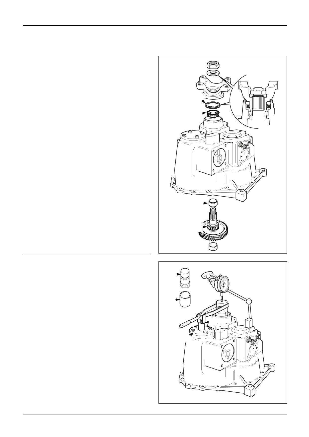
9
Transfer Gear/Output Shaft Assembly
Note: Make sure that the layshaft bearing outer cup is fitted
to the rear casing before fitting the transfer gear/output
shaft.
a Liberally coat output shaft inner bearing with JCB
HP Grease before fitting inner bearing P.
S
b Fit the service solid spacer N (13.70 mm) over
R
output shaft and assemble into casing.
c Lightly oil output shaft outer bearing and cup R and
fit to output shaft, do not fit oil seal S at this stage.
N
P
A388000
10
a Fit special tool sleeve A which temporarily replaces
the output yoke and secure with special tool nut B,
torque tighten to 50 Nm (36.9 lbf ft).
B
Note: Check for end float while tightening nut B, if there is
no end float check:
The bearing cups are pushed fully into the casing.
A
The correct bearings are fitted, check parts
catalogue.
The solid spacer N is 13.70 mm.
D
b Ensure that the layshaft setting ring is slightly below
layshft cover facing on the rear case. Fit special tool
C
support pillar C (892/01076) so that the fork end
engages in special tool nut B, tighten bolt D.
A396650
9803/3280
Issue 1
Section F
Transmission
Section F
112 - 4
Synchro Shuttle Gearbox
112 - 4
Assembly (cont'd)
B
E
11
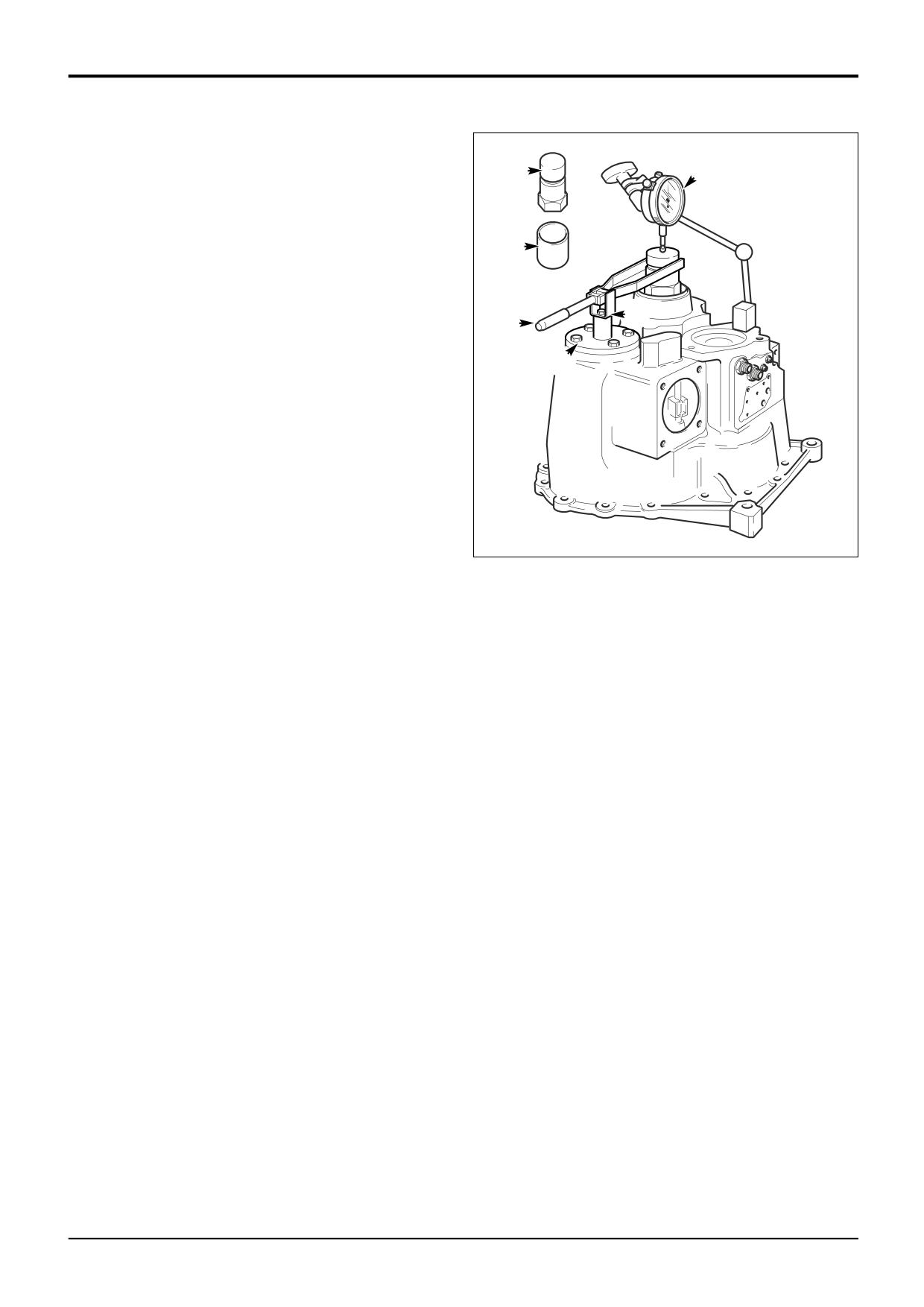
a Fit dial test indicator E (DTI) .
b Set torque wrench F to 35 Nm and measure the end
float while rotating the output shaft.
A
c To select the right size spacer, subtract the end
float obtained at step 11b from the solid spacer
(13.70 mm). Also subtract 0.120 mm to allow for
D
F
theoretical bearing tolerance and pre load. If there is
no spacer of this size, fit the next smallest spacer.
C
Example
Service spacer
13.70
Subtract end float
0.41
Total
13.29
Subtract tolerance & preload
0.12
Result
13.17
Use next smallest spacer ie.
13.15
A396650
d Remove special nut B and sleeve A. Remove rear
bearing and 13.70 mm spacer. Fit correct size
spacer (Do no fit the oil seal at this stage). Take care
to avoid damaging the outer bearing.
e Fit sleeve A and initially tighten nut B to 50 Nm (36.9
lbf ft). Check there is no end float and rolling torque
less than 1.5 Nm (1.0 lbf ft). If the rolling torque
exceeds 1.5 Nm (1.0 lbf ft) check that the output
shaft has been assembled correctly.
f
If the rolling torque measured is too high, fit the next
larger size spacer. If there is end float, fit the next
smaller size spacer.
9803/3280
Issue 2*
Section F
Transmission
Section F
112 - 5
Synchro Shuttle Gearbox
112 - 5
Assembly (cont'd)
12
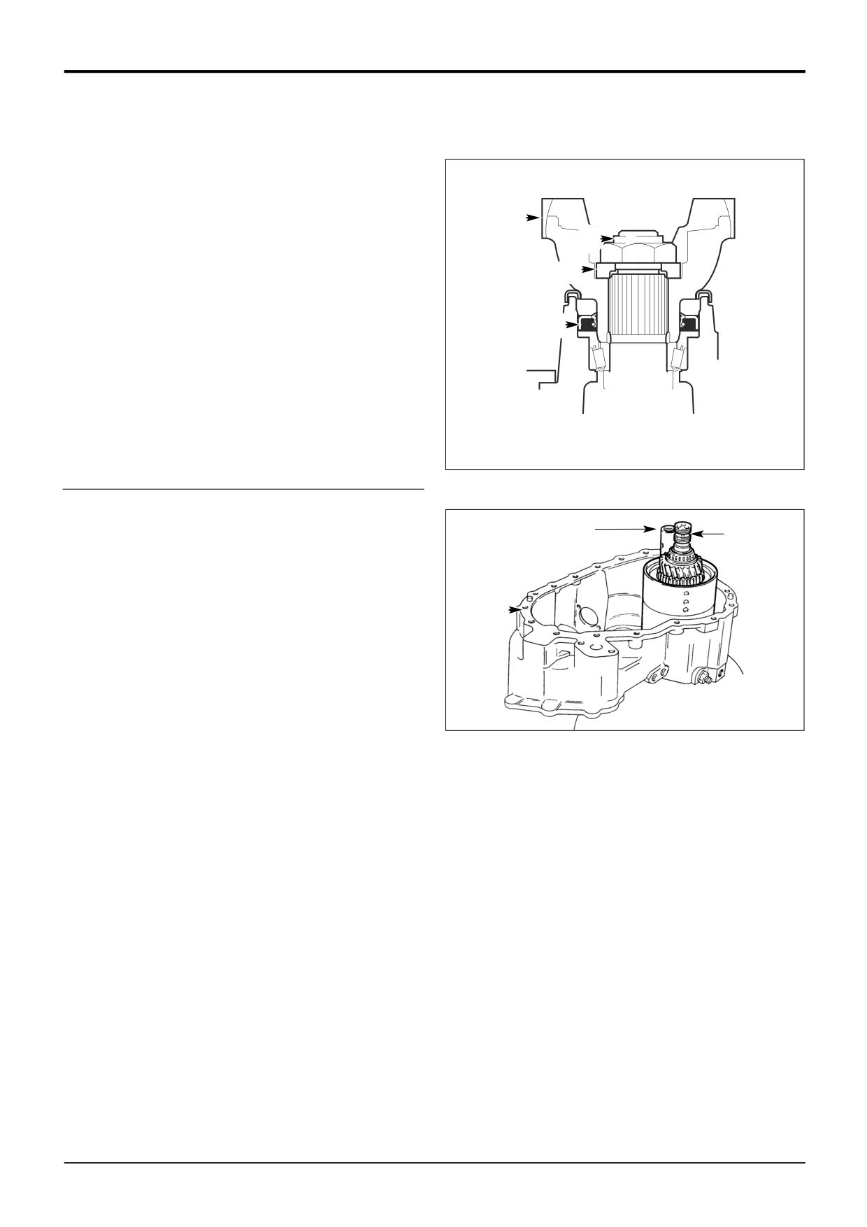
a Remove nut B and sleeve A. Fit new oil seal S,
grease between seal lips before fitting. Note that the
seal does not fix to the back of the housing - use
servicel tool to locate the seal. Fit the output yoke Y.
Y
b Fit the stepped washer W the correct way round
T
with the plain face uppermost as shown.
W
c Fit NEW retaining nut T and progressively torque
tighten to 300 Nm (221 lbf ft). Provided the correct
size spacer has been selected, the rolling torque
S
should be 2.0 Nm (1.5 lbf ft) when nut T is fully
torque tightened.
Note: If the rolling torque measured is too high, fit the next
larger size spacer. If the rolling torque is too low, fit the next
smaller size spacer.
A388180
d Finally, carefully stake nut T into slot using a
square-ended staking tool.
13
Press idler gear spindle into front casing.
13
Note: Before proceding further, make sure that the 3 shaft
14
front bearing outer cups are correctly located inside the
casing V.
14
Grease forward reverse shaft front bearing, then
carefully lower forward/reverse unit into casing. Fit the
V
shaft sealing rings and smear with grease.
221180
9803/3280
Issue 1
Section F
Transmission
Section F
112 - 6
Synchro Shuttle Gearbox
112 - 6
Assembly (cont'd)
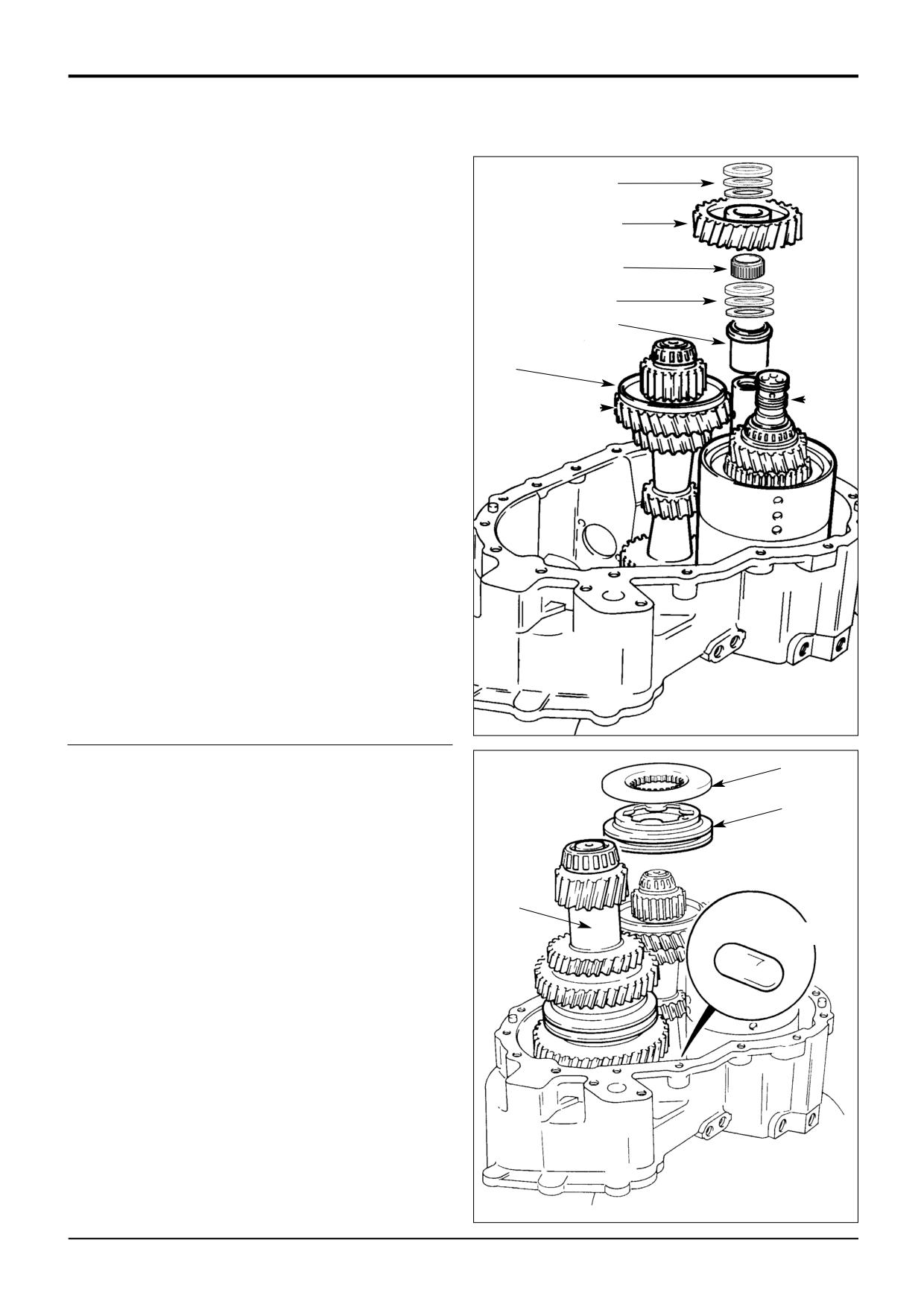
15
Smear mainshaft output end bearing with JCB HP
19
Grease and place mainshaft L in position, followed by
the forward/reverse assembly M.
18a
16
Fit idler gear spacer.
17a
17
Fit thrust washers and bearing assembly. Lubricate and
*
fit the needle roller bearing 17a.
17
18
Fit synchro cone to 3rd gear (mainshaft L). Fit the idler
16
gear 18a to the spindle whilst tilting mainshaft L to one
side.
18
19
Fit thrust washers and bearing assembly.
*
M
L
S407370
21a
20
Smear front end bearing of layshaft with JCB HP
Grease, and carefully lower layshaft into position.
21
21
If re-using synchro assembly fit the parts in their original
positions.
22
Using a suitable wire support locate interlock plunger
into its bore. A smear of grease will hold the plunger in
20
position. If required, access is available via a1/4
BSP
side drilling.
22
221090
9803/3280
Issue 2*
Section F
Transmission
Section F
112 - 7
Synchro Shuttle Gearbox
112 - 7
Assembly (cont'd)
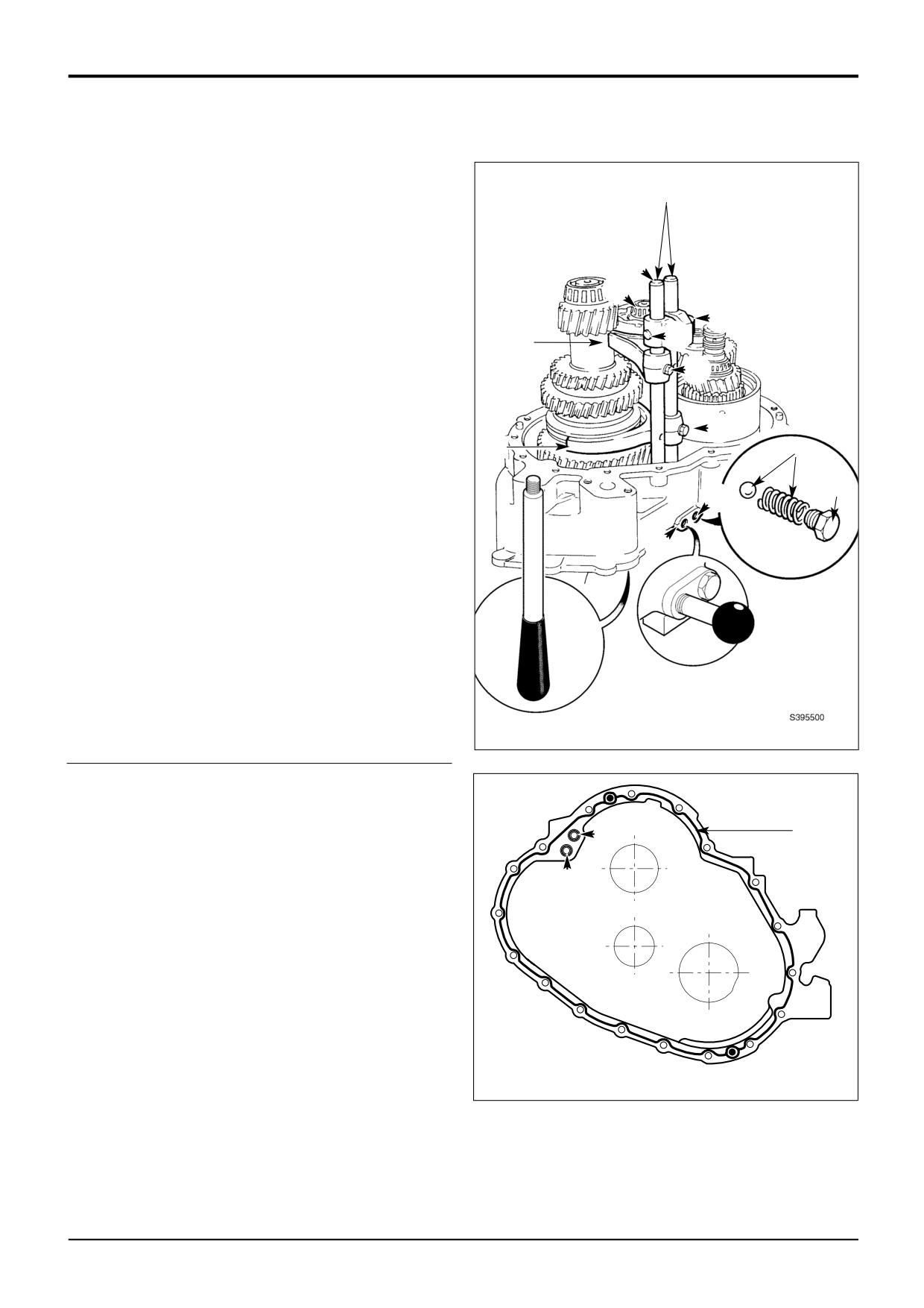
23
Fit selector forks into position.
24
24
Slide selector rods into position, taking care not to
dislodge the interlock plunger. Apply JCB Threadlocker
and Sealer to selector fork retaining screws H, and
tighten to 35 Nm (26 lbf ft).
J
25
Fit 1st gear selector detent ball and spring at position A.
M
Apply JCB Threadlocker and Sealer to the detent plug
25a, screw in and tighten.
H
23
H
26
Temporarily fit the 3rd and 4th gear selector detent
assembly at position B, do not apply sealant to the plug
H
at this stage.
27
Check that each gear engages fully, and that the
interlock plunger prevents simultaneous engagement of
H
23
2 ratios.
25
28
Remove the 3rd and 4th gear selector detent assembly
25a
from position B. Lift the selector rod J to select 4th
A
gear. With 4th gear selected, temporarily lock the rod in
in position by screwing in service tool 892/01077 at B.
Temporarily fit service tool 892/01078 to the torque
B
converter end of mainshaft M. If the tool is not available
a suitable M8 bolt approximately 100 mm long can be
used.
29
Apply a bead of JCB Multigasket to mating face of
casing. Insert 'O' rings Z. Smear grease onto reverser
shaft ring seals, and apply JCB HP Grease to bearings
29
prior to fitting output end casing.
Z
Note: Make sure that the forward/reverse shaft ring seals are
in good condition before fitting output end casing.
Z
A388010
9803/3280
Issue 1
Section F
Transmission
Section F
112 - 8
Synchro Shuttle Gearbox
112 - 8
Assembly (cont'd)
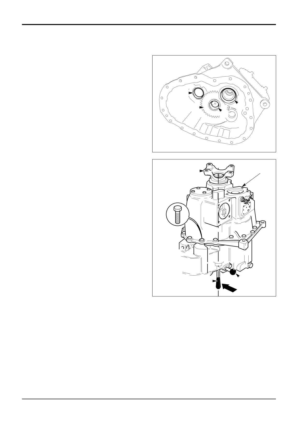
30
Make sure that the 3 bearing outer cups C are correctly
located; note that 2 cups locate inside the casing and 1
locates in the centre of the output shaft transfer gear G.
Carefully lower rear casing into position. Note that the
forward/reverse unit shaft engages with the casing first,
followed by 3rd/4th gear selector rod. To ensure that
the mainshaft locates with the output shaft it will be
necessary to push on tool T to keep the shaft correctly
C
aligned. Rotate the output shaft S back and forth to
engage the gears on the layshaft. Do not use excessive
C
force when fitting the casing.
G
C
31
Apply JCB Threadocker and Sealer to bolts and torque
to 56 Nm (42 lbf ft).
32
Remove service tool at position B. Fit the detent ball
and spring. Apply JCB Threadlocker and Sealer to
selector detent plug, install and tighten.
A395340
30
S
31
B
T
9803/3280
Issue 1
Section F
Transmission
Section F
112 - 9
Synchro Shuttle Transmission
112 - 9
Assembly (cont'd)
33
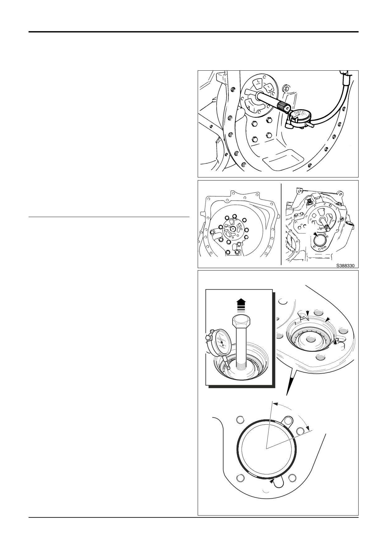
End Float Checking - Forward/Reverse Unit
Measure end float of forward/reverse unit shaft which
*
should be 0.01 to 0.16 mm (0.0004 to 0.006 in).
Note: Rotate shaft whilst measuring to seat bearings fully.
Position pointer of dial test indicator (DTI) on the chamfer of
the shaft, not the end face. This will ensure a constant
reading is given.
The forward/reverse shaft and its associated
components are manufactured using a ‘Setright’
system. Provided components are assembled correctly
the end float will be within the limits given above.
S221201
If there is no float, or too much end float, separate the
casings and check that the bearings inner and outer
cups are fitted correctly. If the forward/reverse shaft
and clutch assemblies have been dismantled check that
the assembly has been carried out correctly.
34
End Float Setting - Mainshaft
A
If the mainshaft, output shaft and/or associated
bearings have been renewed, the shaft end float must
be reset.
a Remove the torque converter housing and position
the gearbox to gain access to setting ring A.
b Using service tool 892/01079 tighten the setting ring
to 25 Nm
(18.4 lbf ft) whilst at the same time
rotating the shaft via the output yoke (a gear must
be engaged). Do not over tighten the ring.
Y
Overtightening will damage the bearings.
A
c Undo the ring a small amount to obtain a shaft end
float of 0.03 to 0.08 mm (0.001 to 0.003 in). To
measure the endfloat screw in a bolt (or service tool
892/01078) at the threaded hole in the end of the
X
shaft. Set up a DTI with the probe on the chamfer of
the shaft. Zero the DTI. Rotate the shaft and at the
same time pull up on the bolt, noting the reading on
the DTI. Screw the ring in or out until the end float is
correct.
d When the correct setting has been obtained, stake
the setting ring to the casing as shown at Y (see the
Z
note below). Note that once staked the setting ring
can not be used again. If the ring is disturbed it must
be discarded and a new one used to re-set the end
float.
Note: If the slots in the setting ring fall close (within zone Z)
to the staking position Y, stake at position X instead. In this
event the ring must also be folded on one side at position Y,
fold on the side furthest away from the slot in the ring. This is
important as the ring will otherwise restrict the flow of
lubrication oil.
X
A396640
9803/3280
Issue 2*
Section F
Transmission
Section F
112 - 10
Synchro Shuttle Gearbox
112 - 10
Assembly (cont'd)
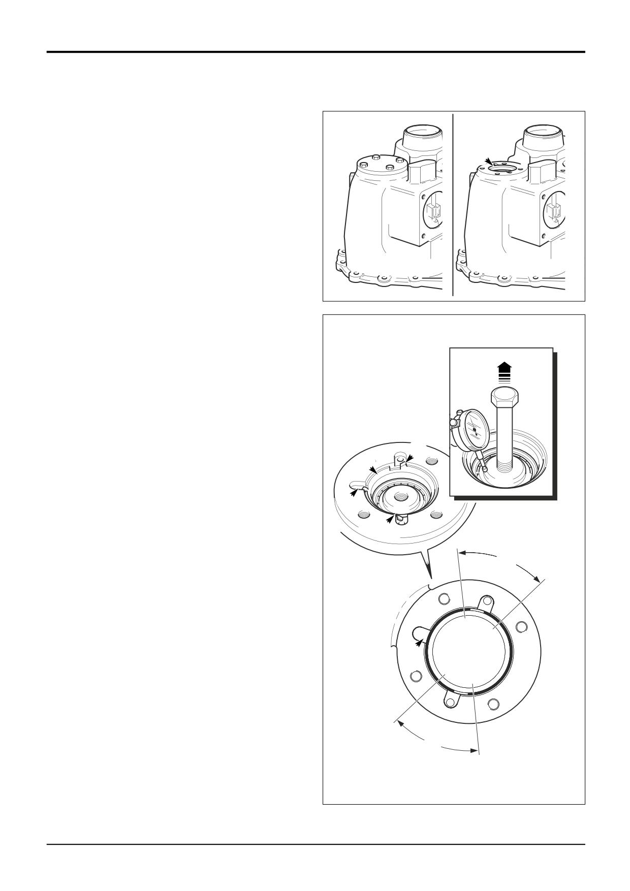
35
End Float Setting - Layshaft
If the layshaft and/or its bearings have been renewed,
the shaft end float must be reset.
A
a Fit the torque converter housing and stand the
gearbox on the housing.
b Using service tool 892/01079 tighten the setting ring
A to 25 Nm
(18.4 lbf ft) whilst at the same time
rotating the shaft via the output yoke (a gear must
be engaged). Do not over tighten the ring.
Overtightening will damage the bearings.
c Undo the ring a small amount to obtain a shaft end
float of 0.03 to 0.08 mm (0.001 to 0.003 in). To
measure the endfloat screw in a bolt (or service tool
892/01078) at the threaded hole in the end of the
shaft. Set up a DTI with the probe on the chamfer of
the shaft. Zero the DTI. Rotate the shaft and at the
same time pull up on the bolt, noting the reading on
the DTI. Screw the ring in or out until the end float is
correct.
d When the correct setting has been obtained, stake
the setting ring to the casing as shown at the two
positions Y (see the note below). Note that once
staked the setting ring can not be used again. If the
ring is disturbed it must be discarded and a new one
used to re-set the end float.
Y
Note: If the slots in the setting ring fall close (within zone Z)
A
to the staking positions Y, stake at position X instead. In this
event the ring must also be folded on one side at the two
positions Y, fold on the side furthest away from the slot in
X
the ring. This is important as the ring will otherwise restrict
the flow of lubrication oil.
Y
e Using a new gasket, refit the layshaft bearing cover.
Apply JCB Threadlocker and Sealer to the fixing
Z
bolts and tighten to 56 Nm (42 lbf ft).
X
Z
A396630
9803/3280
Issue 1
Section F
Transmission
Section F
112 - 11
Synchro Shuttle Gearbox
112 - 11
Assembly (cont'd)
36
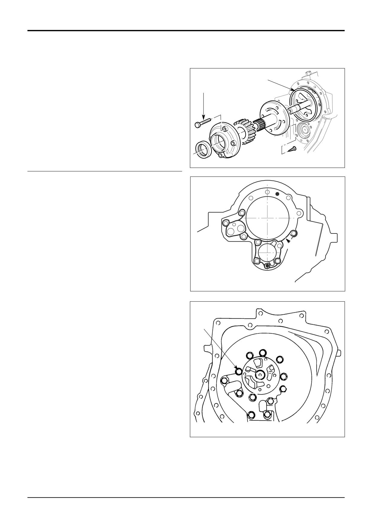
Place new pump sealing ring in position. Make sure that
the charge pump drain hole is clear before fitting a new
36
oil seal to the pump housing.
37
15
37
Install pump taking care to align mounting holes. Apply
JCB Threadlocker and Sealer to bolts and, using new
sealing washers, tighten to 28 Nm (21 lbf ft).
A388140
38
Apply a bead of JCB Multigasket to the mating face of
the gearbox cover as shown at A. Refit the torque
converter housing. Apply JCB Threadlocker and Sealer
to the 12 bolts and tighten to 56 Nm (42 lbf ft).
A
A388020
38
221260
9803/3280
Issue 2*
Section F
Transmission
Section F
112 - 12
Synchro Shuttle Gearbox
112 - 12
Assembly (cont'd)
39
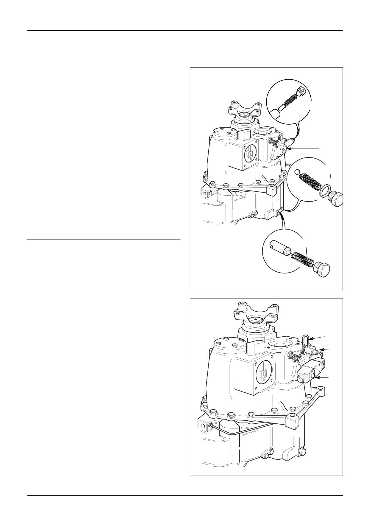
Fit torque converter pressure relief valve assembly 39a;
Fit the valve ball and spring. Ensure that larger diameter
of spring is located securely over the spigot on the plug.
Use a new sealing washer, apply JCB Threadlocker and
Sealer to the plug, then tighten.
Fit the torque converter pressure regulating valve
41
assembly 39b; Fit the spool and spring. Apply JCB
Threadlocker and Sealer to the plug, then tighten.
40
Using a new gasket mount pressure maintenance valve
onto casing. Apply JCB Threadlocker and Sealer to
bolts and tighten to 10 Nm (7.4 lbf ft).
44
Note: To avoid contamination of sealant printed on gasket
face keep in protective wrapper until needed.
39b
41
Assemble pressure maintenance valve spool and spring
into adaptor block. Apply JCB Threadlocker and Sealer
to plug, fit and tighten. Do not overtighten as damage
to the aluminium housing could result.
39a
42
Fit new ‘O’ rings around ports on mating face of
solenoid valve. Mount solenoid valve onto pressure
maintenance valve, ensuring that port 'P' aligns with
metering orifice in the pressure maintenance valve
body. Apply JCB Threadlocker and Sealer to capscrews
and tighten to 5Nm (3.7 lbf ft).
A387980
43
Fit the 4 wheel drive solenoid valve. Fit the hydraulic
pipe 43a.
43a
43
42
A388260
9803/3280
Issue 1
Section F
Transmission
Section F
112 - 13
Synchro Shuttle Gearbox
112 - 13
Assembly (cont'd)
44
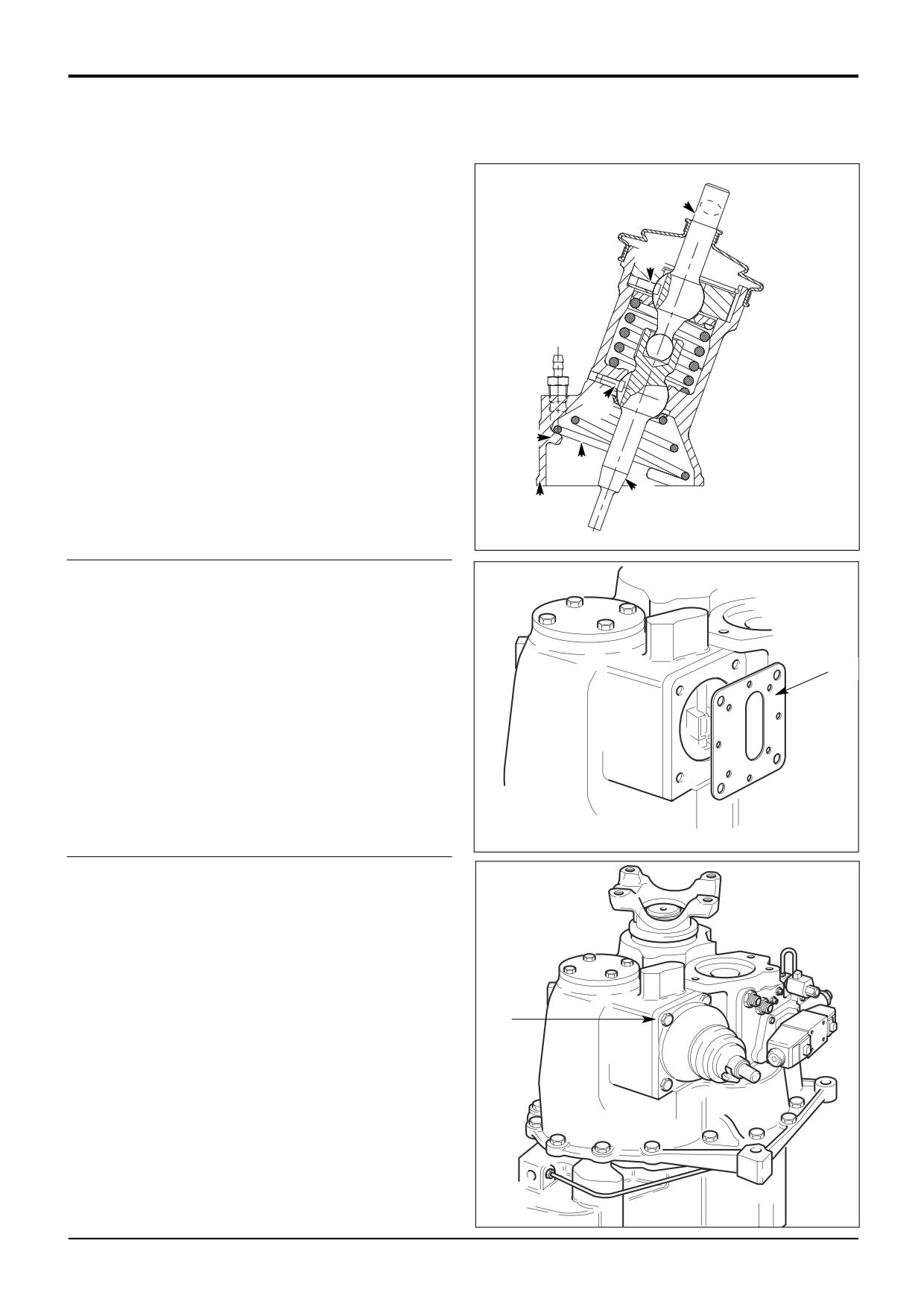
If the gear lever turret assembly has been dismantled,
apply grease liberally to the working surfaces before
assembling. Assembly is the reverse of the procedure
A
detailed in Gearbox - Dismantling, Step 1, but note the
following:
B
a Be sure to locate the slots in the levers A with the
*
pegs B in the housing E.
b After fitting spring C, rotate it so that the end of the
bottom coil butts with the the spigot D in the
housing E.
B
D
C
A
E
A397010
45
Locate a new gasket (not shown) on the casing followed
by the gear lever turret baffle plate. Make sure the plate
is the correct way round.
45
A388270
46
Locate a second gasket and then fit the turret
assembly.
Apply JCB Threadlocker and Sealer to mounting bolts
and tighten to 56 Nm (42 lbf ft). Check for gear
selection.
46
9803/3280
Issue 2*
Section F
Transmission
Section F
112 - 14
Synchro Shuttle Gearbox
112 - 14
Assembly (cont'd)
Note: It is recommended that a 75 micron (0.075mm)
service suction strainer (892/00970) is fitted to clean the
system after a major overhaul.
Remove the service strainer and fit a production strainer
after the first 100 hours operation. Renew the oil.
47
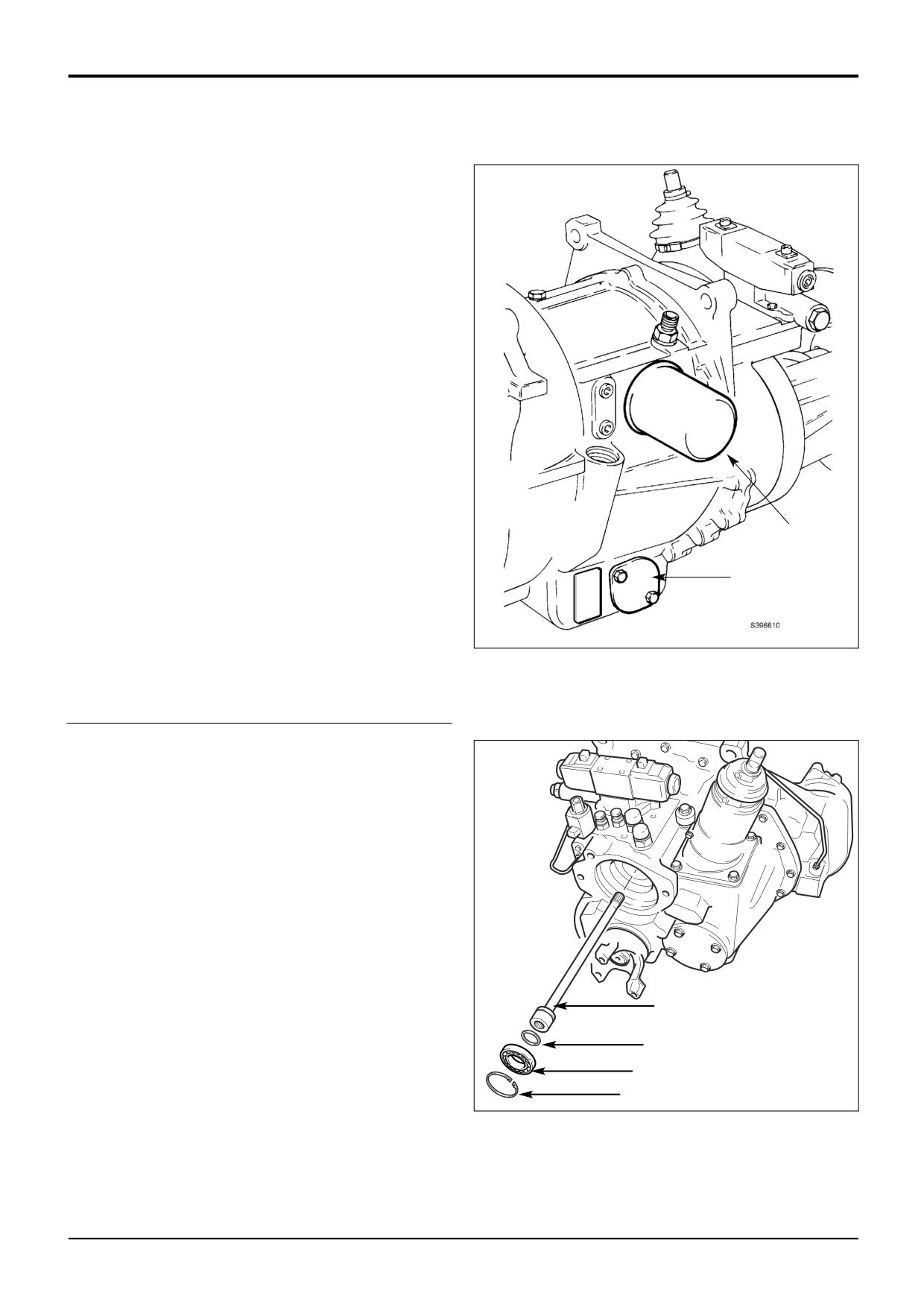
Using a new gasket, install suction strainer. Apply JCB
Threadlocker and Sealer to bolts and tighten to 10 Nm
(7 lbf ft).
48
Fit a new filter:
a Smear seal with transmission oil.
b Screw the filter on until it just contacts the filter
head.
c Turn the filter at least another 3/4 of a turn.
49
Install dipstick/oil filler tube (not shown) as follows:
48
a Fit nut to tube followed by seal.
b Insert tube fully down bore in casing. Engage nut
47
and tighten down loosely onto seal.
c Tighten nut fully after tube has been correctly
phased.
See 2/4 Wheel Drive Clutch for hydraulic 4WD
dismantling and assembly procedures.
50
Fit a new sealing ring 50a to the pump drive shaft. Insert
the pump drive shaft followed by bearing 50b and
circlip 50c.
Note: The main hydraulic pump may be fitted at this stage,
or, after the gearbox has been refitted to the machine.
50
50a
50b
50c
A388040
9803/3280
Issue 1
Section F
Transmission
Section F
113 - 1
Synchro Shuttle Gearbox
113 - 1
Reverser Unit - Dismantling
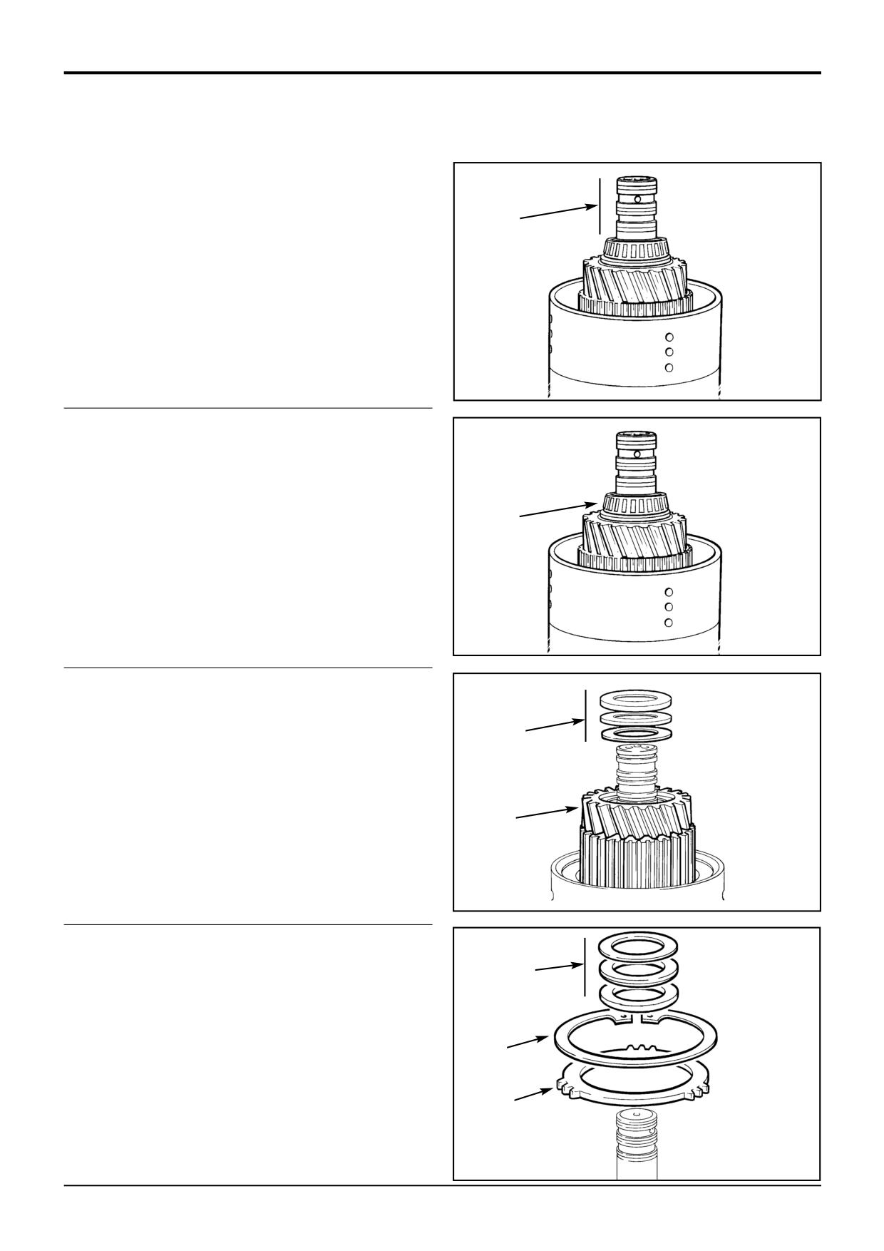
1
Carefully remove piston ring seals.
Note: If the piston ring seals are excessively worn then
check for burrs or damage on the shaft grooves. If necessary
1
remove burrs with a fine grade abrasion paper and oil.
S232720
2
Remove the taper bearing using pullers.
*
2
S232720
*
3
Remove the thrust bearing and thrust washers.
4
Withdraw the gear and splined hub assembly 4 with the
*
needle roller bearing and spacer. Note the location of
3
the spacer to ensure it is returned to its original position
on re-assembly.
4
S407220
*
5
Remove the thrust bearing and thrust washers.
6
Remove the clutch friction/counter plates retaining
5
circlip.
7
Remove pressure (end) plate.
6
7
S407250
9803/3280
Issue 2*
Section F
Transmission
Section F
113 - 2
Synchro Shuttle Gearbox
113 - 2
Reverser Unit - Dismantling (cont'd)
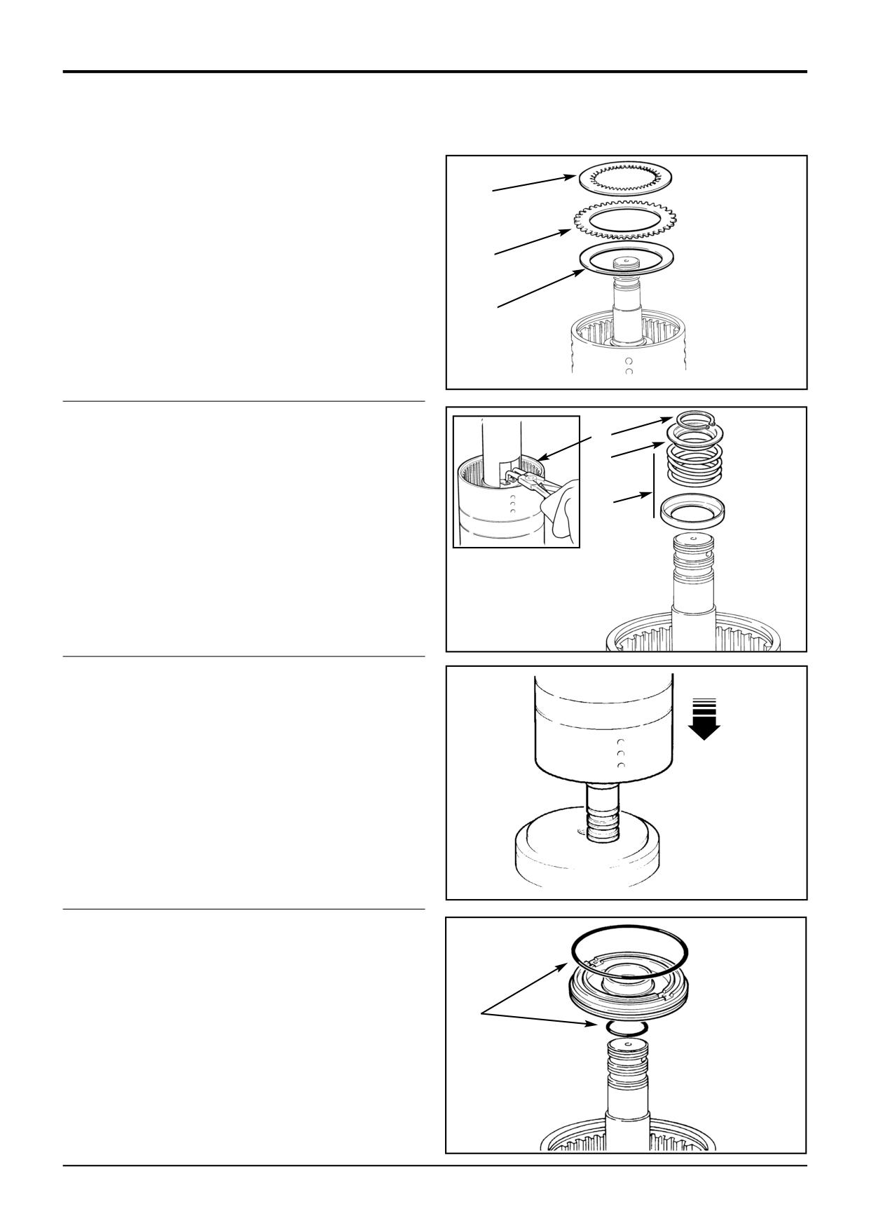
8
Remove the clutch friction/counter plates. Keep them
together in sets, DO NOT mix the plates with those from
other clutches.
8
9
Remove last counter plate.
*
10
Remove disc spring.
9
10
S232741
11
Position clutch assembly in press to compress piston
spring then remove circlip.
11
12
Lift off spring retaining plate.
12
*13
Remove spring and oil baffle.
13
S145000
S407190
14
Knock the clutch shaft on a piece of aluminimum (or
wood) to remove the piston.
Note: If the piston does not loosen when the clutch shaft is
knocked on aluminimum, then hand pump air down the shaft
oil inlet hole.
S145010
*
15
Remove and discard piston and shaft ‘O’ rings.
16
Repeat steps 2 to 15 to dismantle the opposite clutch.
*
Note that a spacer is not fitted on the opposite
(Forward) clutch. Refer to step 4.
15
S407200
9803/3280
Issue 2*
Section F
Transmission
Section F
113 - 3
Synchro Shuttle Gearbox
113 - 3
Reverser Unit - Assembly
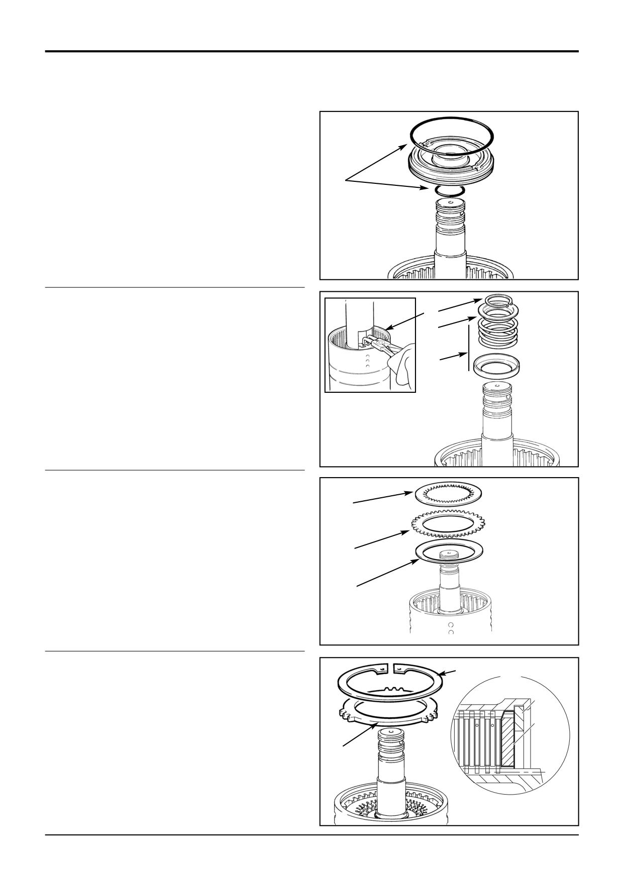
1
Fit new 'O' rings onto the piston and shaft, lubricate
with oil then press piston fully into bore of clutch
housing.
1
S407200
*2
Install the oil baffle and piston spring, make sure the
spring seats in the piston.
4
3
Fit the spring retaining plate.
3
4
Compress spring and secure with circlip.
2
S145000
S407190
5
Fit the disc spring assembly. Fit the assembly so that
the outer diameter curves away from the clutch piston.
7
6
Firstly, fit one counter plate.
7
Fit one friction plate followed by one steel counter plate.
6
8
Continue fitting alternate friction and plain steel plates,
finishing with a friction plate.
5
S232741
9
Fit the pressure (end) plate. Make sure that the
10
chamfered face is fitted facing the clutch pack as
shown at A. Make sure that the prongs on the pressure
A
plate DO NOT locate in the large grooves in the hub (the
10
ones with drilled holes).
9
10
Fit the clutch friction/counter plates retaining circlip.
*
Using an air line, blow air down the shaft oil inlet hole
and check the piston and clutch pack is free to operate
9
smoothly.
A402700
S217580
9803/3280
Issue 3*
Section F
Transmission
Section F
113 - 4
Synchro Shuttle Gearbox
113 - 4
Reverser Unit - Assembly (cont'd)
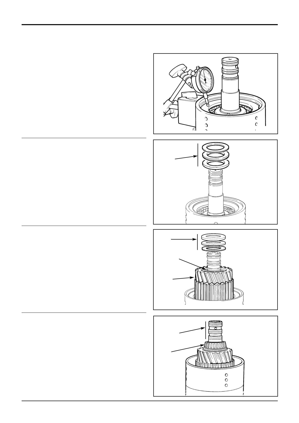
11
Using a dial test indicator as shown, measure the end
float of the pressure (end) plate, which should be 3.2 to
4.4 mm (0.126 to 0.173 in). If necessary, fit shim
between the retaining circlip and pressure (end) plate to
correct end float inaccuracies.
*
S217590
12
Fit the thrust bearing and thrust washers.
12
S407240
13
Fit gear and splined hub assembly.
15
Note: Prior to fitting gear, align teeth of clutch plates using a
thin rod (screwdriver).
*
14
Fit the spacer followed by the needle roller bearing.
14
Note: Ensure that the spacer is fitted first.
*
*
15
Fit the thrust bearing and thrust washers.
13
S407220
16
Smear the clutch end bearing with JCB HP Grease and
press the bearing onto shaft.
*
17
Fit piston ring seals, refer to Piston Ring Seals - Fitting
17
Procedure.
18
Repeat steps 1 to 16 for the opposite clutch. Note that
*
16
a spacer is not fitted on the opposite (Forward) clutch.
Refer to step 14.
S232720
9803/3280
Issue 2*
Section F
Transmission
Section F
114 - 1
Synchro Shuttle Gearbox
114 - 1
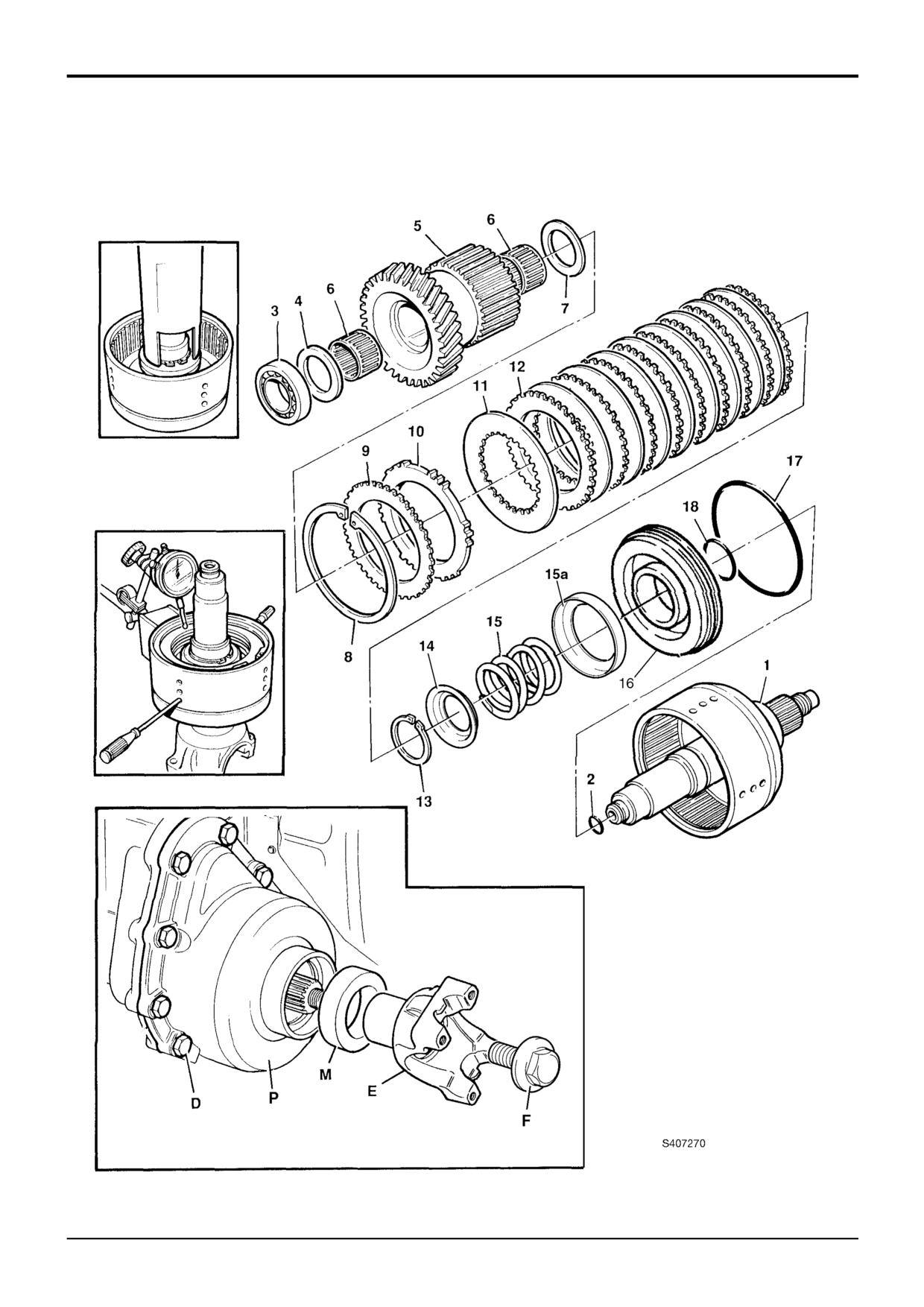
Hydraulic 2/4 Wheel Drive Unit (4WD Pressure ON)
Y
B
9803/3280
Issue 2*
Section F
Transmission
Section F
114 - 2
Synchro Shuttle Gearbox
114 - 2
Hydraulic 2/4 Wheel Drive Unit
(4WD Pressure ON)
Dismantling
Assembly
Note: To aid working on this item, use the output yoke as a
If only the clutch pack has been removed, begin at step 4.
stand.
*1
Grease the shaft, fit new 'O' rings 17 and 18 then locate
Before dismantling the unit drain the gearbox oil.
piston 16 over the shaft and into the housing.
1
Hold the yoke E using service tool 892/00812 and undo
2
Locate oil baffle 15A, spring 15 into the piston and
bolt F. Remove the yoke. Carefully remove and discard
position the retainer plate 14 over the spring.
oil seal M. Be sure not to damage the seal housing.
3
Using a press and adapter Y, compress spring 15 and
2
Undo bolts D. Lift off the 4WD casing P. Lift out the
fit circlip 13.
4WD unit from the gearbox.
4
Build up the clutch pack, installing friction plates 11 and
3
Remove bearing 1, only if to be renewed.
counter plates 12 alternately, starting with a counter
plate and ending with a friction plate.
4
Remove seal ring 2. Note, If the piston ring seal is
damaged or excessively worn then check for burrs or
*5
Install pressure plate 10, shim(s) 9 and circlip 8. Using
damage on the shaft groove. If necessary remove burrs
an air line, blow air down the shaft oil inlet hole and
with a fine grade abrasion paper and oil.
check the piston and clutch pack is free to operate
smoothly.
*5
Using a puller remove the 4WD output gear 5, together
with its bearing 3, needle roller bearings 6 and thrust
6
Measure the clutch pack end float using two
washer 4. Remove thrust washer 7. (Note that thrust
screwdrivers as shown at B. End float should be
washers 4 and 7 are not interchangeable).
*
between 1.0 mm and 2.3 mm. Adjust as necessary, by
adding or removing shims 9.
6
Remove circlip 8 and shim(s) 9 if fitted. Retain any
shims as a set for assembly.
7
Fit thrust washer 7, 4WD gear 5, needle roller bearings 6
and thrust washer 4.
7
Remove pressure plate 10, the clutch pack friction
plates 11 and counter plates 12.
8
Press bearing 3 squarely onto the shaft to seat on thrust
washer 4, taking care not to exert any force on the
Note: If only the clutch pack was to be removed, the job is
housing i.e. rest the unit on the opposite shaft end, not
now complete.
the housing.
8
Using a suitable press and an adapter similar to Y,
9
Fit new seal 2.
compress spring 15 and remove circlip 13.
10
If required, press a new bearing 1 into position, taking
9
Remove spring retainer plate 14, spring 15 and oil baffle 15A.
care not to exert any force on the housing (see Step 8).
10
Withdraw piston 16 then remove and discard 'O' rings
11
Fit the 2/4WD unit to the gearbox.
17 and 18.
12
Apply a thin bead of JCB Multigasket to the 4WD
Note: The piston housing cannot be separated from the
mating face of the gearbox front case. Fit the case P,
shaft, as on the other types of 2/4WD units.
apply JCB Threadlocker and Sealer to bolts D and
*
progressively torque tighten to 56 Nm, 46 lbf ft.
Inspection
13
The 4WD clutch and its associated components are
Carry out a visual inspection of the friction and counter
manufactured using a ‘setright’ system. Provided that
plates.
components have been assembled correctly, the shaft
Counter plates - light scoring/polishing is permissible, plates
end float will be 0.01 to 0.16 mm (0.0004 to 0.006 in).
*
that are not flat, worn or heavily marked or scored must be
Rotate the shaft by hand and ensure that it runs
replaced with a new set.
smoothly. Pull the shaft up and down to detect any
Friction plates - the cross hatching should be clearly visible,
excessive end float. If there is excessive end float or the
plates that are not flat, have friction material damage or
shaft runts roughly, dismantle the unit and check for
scoring must be replaced with a new set.
correct assembly.
Do not mix old, new and worn plates.
14
Fit a new oil seal M, fit the output yoke E, and flanged
bolt F. Torque tighten the bolt to 395 Nm; 291 lbf ft.
Two different suppliers of the thinner friction plates (1.6 to
1.7 mm, 0.062 to 0.067 in approx) have been used (identify
as brown or green), do not mix the different plates in the
same clutch pack.
Inspect the mating faces of the gearbox and 4WD casings
for damage.
9803/3280
Issue 2*
Section F
Transmission
Section F
115 - 1
Synchro Shuttle Gearbox
115 - 1
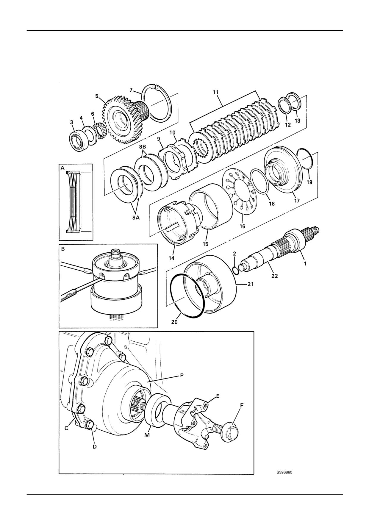
Hydraulic 2/4 Wheel Drive Unit (4WD Spring ON)
9803/3280
Issue 1
Section F
Transmission
Section F
115 - 2
Synchro Shuttle Gearbox
115 - 2
Hydraulic 2/4 Wheel Drive Unit
(4WD Spring ON)
Dismantling and Assembly
Inspection
Note: Before dismantling the unit drain the gearbox oil.
Carry out a visual inspection of the friction and counter
plates.
Dismantling
Counter plates - light scoring/polishing is permissible, plates
1
Hold the yoke E using service tool 892/00812 and undo
that are not flat, worn or heavily marked or scored must be
bolt F. Remove the yoke. Carefully remove and discard
replaced with a new set.
oil seal M. Be sure not to damage the seal housing.
Friction plates - the cross hatching should be clearly visible,
2
Undo bolts D. Lift off the 4WD casing P. Lift out the
plates that are not flat, have friction material damage or
4WD unit from the gearbox.
scoring must be replaced with a new set.
3
Remove bearing 1, only if to be renewed.
Do not mix old, new and worn plates.
4
Remove seal ring 2. Note, If the piston ring seal is
Two different suppliers of the thinner friction plates (1.6 to
damaged or excessively worn then check for burrs or
1.7 mm, 0.062 to 0.067 in approx) have been used (identify
damage on the shaft groove. If necessary remove burrs
as brown or green), do not mix the different plates in the
with a fine grade abrasion paper and oil.
same clutch pack.
5
Pull off the 4WD output gear 5, together with its bearing
Assembly
3, needle roller bearing 6 and thrust washer 4.
Note: Use the pressure test adaptor and clamp assembly
6
Using a suitable press, compress disc springs 8A, 8B
(see Service tools) to ‘bench test’ the clutch. Bench testing
and remove the circlip 7.
will ensure the clutch operates correctly prior to - assembling
and installing in the machine. Refer to Hydraulic 2/4 Wheel
CAUTION: There is approximately 26700N (6000lbf)
Drive Unit, Pressure Testing the 2/4 WD Clutch.
clamping force acting on the springs.
1
Grease the shaft 22 then fit the piston housing 21 by
7
Remove disc springs 8A, 8B, pressure plate 9, shim(s)
pressing the shaft squarely into the housing (make sure
10 (keep the shim(s) separate from the counter plates),
the housing is securely supported on the centre boss).
and clutch pack friction plates and counter plates 11.
2
Fit new O-rings 19 and 20 to piston 17, locate the
8
Remove the clutch drum retaining circlip 12 and
piston into housing 21. Fit spring steel ring 18 ensuring
support washer 13.
that it seats firmly in its groove.
9
Remove clutch drum 14 and actuating sleeve 15 .
3
Place the disc spring 16 into the housing 21.
10
Remove disc spring 16.
4
Position the actuating sleeve 15 onto the disc spring 16.
11
Remove the piston 17 and its spring steel ring 18.
5
Install the clutch drum 14 in the housing. Fit support
washer 13 and drum securing circlip 12.
12
Remove and discard piston O-rings 19 and 20.
6
Build up the clutch pack 11, installing friction plates and
13
Remove the piston housing 21 only if necessary, the
counter plates alternately, starting with a counterplate
housing is a press fit on shaft 22.
and finishing with a friction plate.
7
Install shim(s) 10 and pressure plate 9.
8
Use the output gear 5 to align the clutch plate splines.
Ensure that all the plates are engaged with the gear
shaft splines. Rotate the output gear back and forth to
create maximum backlash then withdraw the gear
taking care not to disturb the pack.
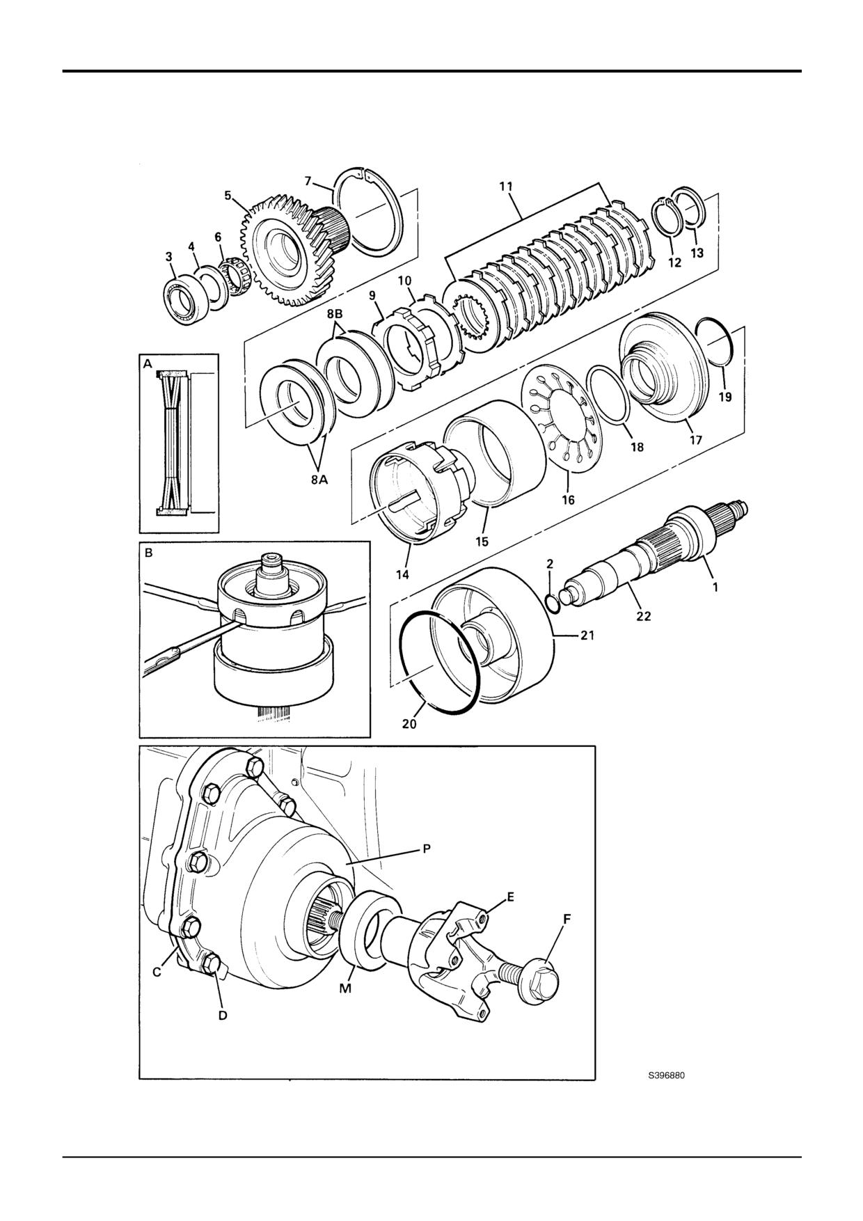
9
Place the first two disc springs 8B with their convex
sides uppermost, onto the clutch pack. (There are four
disc springs, which are identical). Place the other two
disc springs 8A, with their convex sides down, onto the
first two - refer to inset A.
9803/3280
Issue 1
Section F
Transmission
Section F
115 - 3
Synchro Shuttle Gearbox
115 - 3
9803/3280
Issue 1
Section F
Transmission
Section F
115 - 4
Synchro Shuttle Gearbox
115 - 4
Hydraulic 2/4 Wheel Drive Unit
(4WD Spring ON)
Assembly (continued)
10
Using a suitable press, compress the disc springs 8A
and 8B, fit circlip 7.
11
Use levers to remove free play, as shown at B. Measure
the gap between pressure plate 9 and actuating sleeve
15. The gap should be 0.75 - 1.5 mm; 0.030 - 0.059
inches. If necessary fit new shim 10 to achieve the
correct gap. (Shim 10 can be a combination of a single
counter plate, shim (thinner than the counter plate) or
both counter plate and shim). Check that the clutch
pack splines are still aligned - see step 8.
12
Install the 4WD output gear 5 and its needle roller
bearing 6.
13
Install thrust washer 4 and bearing 3.
14
Fit sealing ring 2 and bearing 1.
15
Fit the 2/4WD unit to the gearbox.
16
Apply a thin bead of JCB Multigasket to the 4WD
mating face of the gearbox front case. Fit the case P,
apply JCB Threadlocker and Sealer to bolts D and
*
progressively torque tighten to 56 Nm, 46 lbf ft.
17
The 4WD clutch and its associated components are
manufactured using a ‘setright’ system. Provided that
components have been assembled correctly, the shaft
end float will be 0.01 to 0.16 mm (0.0004 to 0.006 in).
*
Rotate the shaft by hand and ensure that it runs
smoothly. Pull the shaft up and down to detect any
excessive end float. If there is excessive end float or the
shaft runs roughly, dismantle the unit and check for
correct assembly.
18
Fit a new oil seal M, fit the output yoke E, and flanged
bolt F. Torque tighten the bolt to 395 Nm; 291 lbf ft.
9803/3280
Issue 2*
Section F
Transmission
Section F
116 - 1
Synchro Shuttle Gearbox
116 - 1
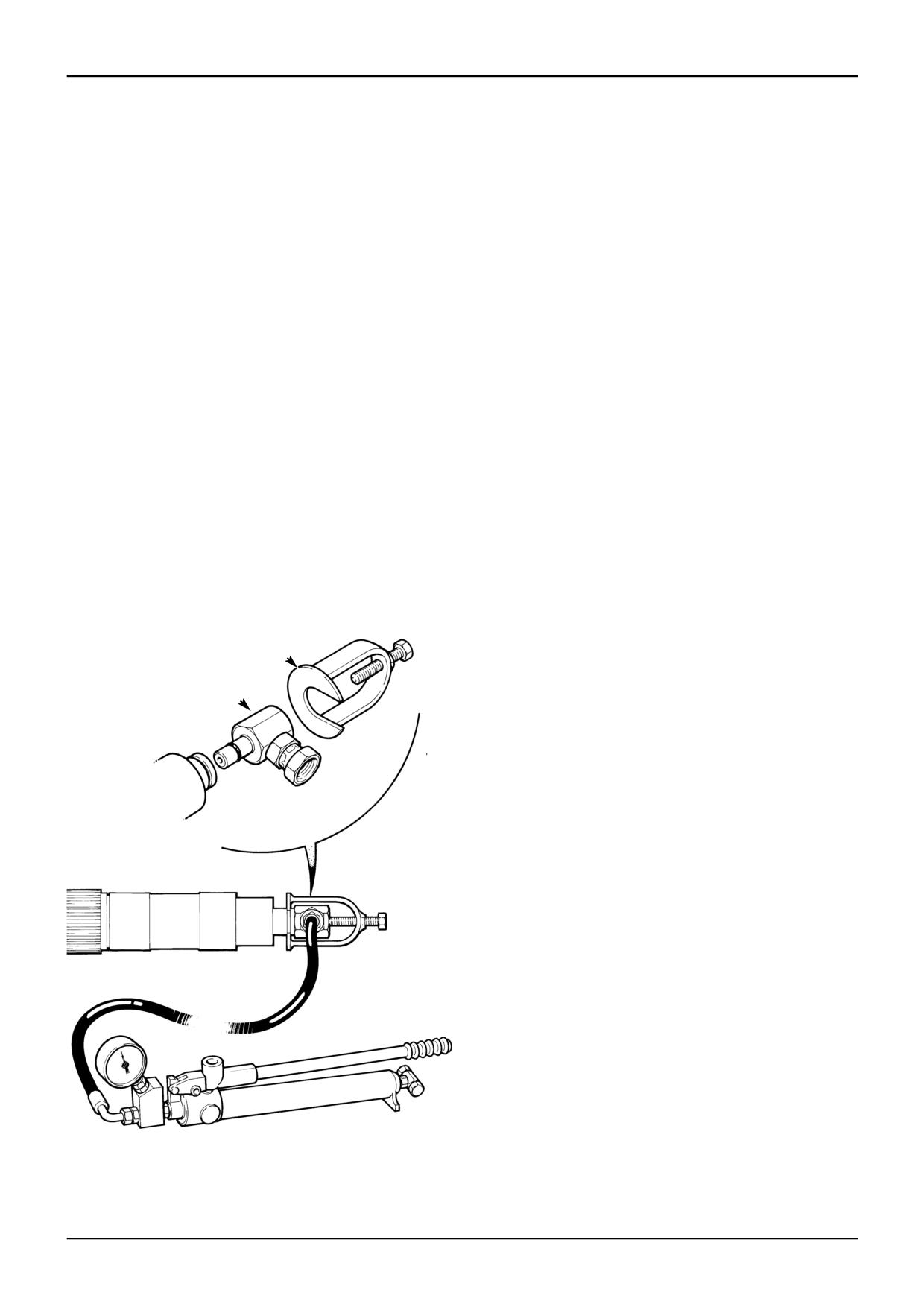
Pressure Testing the 2/4WD Clutch
1
Assemble the 2/4 wheel drive clutch, as described in
‘Assembly’.
2
Check the clutch pack end float and adjust as required
(see Assembly).
3
Using special tool 993/59300, insert the adaptor A into
the oil gallery in the end of the 2/4 wheel drive clutch
shaft as shown. Hold the adaptor in position with
clamp B.
4
Use a hand pump to pressurise the clutch assembly
until gear, item 5 can be turned by hand. Note the
pressure gauge reading - DO NOT EXCEED 200 lb/in2
(13.8 bar).
5
If the pressure gauge reading is between 125 - 135
lbf/in2 (8.6 - 9.3 bar) then the clutch is operating
correctly and can be fitted in the transmission.
6
If however the pressure gauge reading is above 135
lbf/in2 (9.3 bar) then check the clutch for assembly
defects, especially the clutch pack end float (the shim
may not be to the correct thickness). -test after
checking for (and rectifying) assembly defects.
B
A
S185720
9803/3280
Issue 1
Section F
Transmission
Section F
117 - 1
Synchro Shuttle Transmission
117 - 1
Polytetrafluoroethylene (PTFE) Piston Ring Seals - Fitting Procedure
1
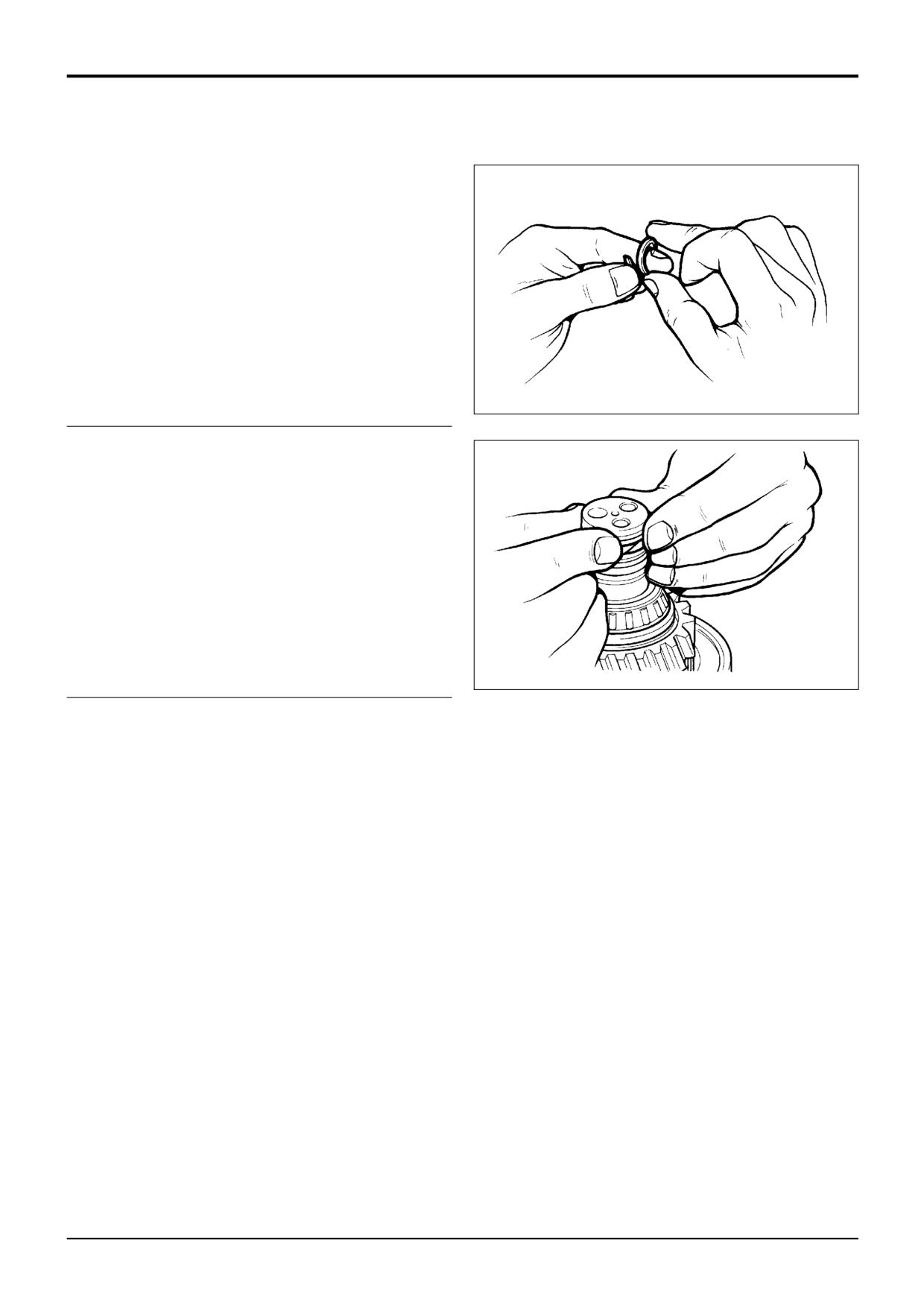
Wind the PTFE piston ring seal around your finger as
shown, so that the seal forms a 'coil'.
157250
2
Smear the seal with grease and then fit the seal to the
shaft.
Make sure that the seal sits below or flush with the
outer diameter of the shaft. If necessary, use finger
pressure as shown to make the seal flush with the shaft.
CAUTION: If the seal is not set below or flush with the outer
diameter of the shaft, then the seal will 'cut' when the shaft is
fitted to its mating component.
157260
9803/3280
Issue 1
Section F
Transmission
Section F
120 - 1
Powershift Gearbox
120 - 1
Removal and Replacement
c
R
M
N
J
K
T
R
d
P
S
L
H
H
d
c
X
F
G
b
a
G
E
a
b
Z
Y
D
B
A401320
9803/3280
Issue 1
Section F
Transmission
Section F
120 - 2
Powershift Gearbox
120 - 2
Removal and Replacement (cont’d)
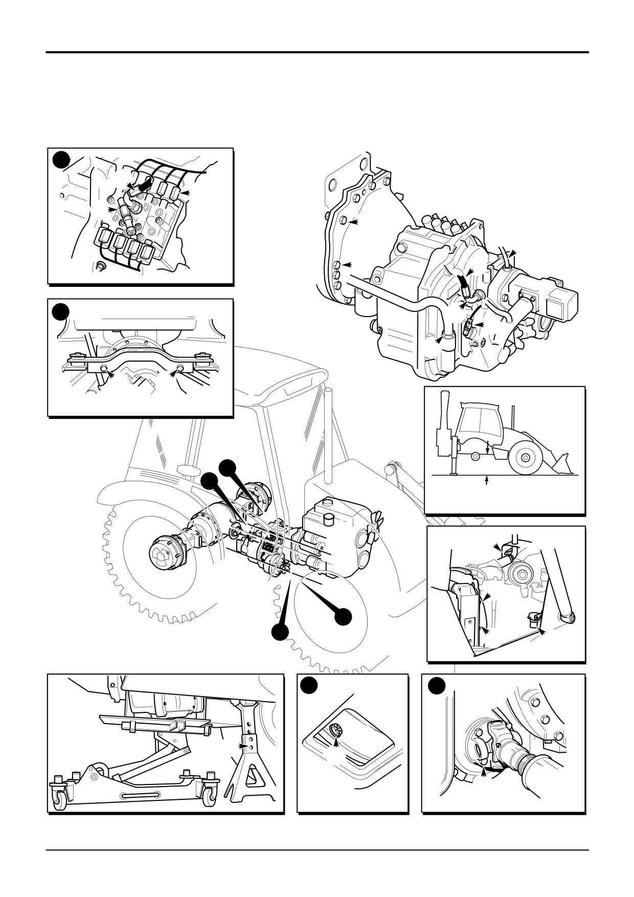
IMPORTANT: The gearbox is heavy. Unless it is safely
10
At a later stage the gearbox and engine assembly is
supported during removal and replacement it could fall and
tilted to allow access to fixing bolts. To prevent damage
cause injury. Make sure that you have access to suitable
as the engine is tilted components must have their
jacks and a gearbox locating ‘cradle’ before attempting to
fixings removed as follows:
remove the gearbox.
a Fuel sediment bowl assembly E (2 bolts).
! WARNING
b Exhaust stack fixing bracket F (2 bolts).
d Radiator fan cowl G (4 bolts).
A raised and badly supported machine can fall on you.
Position the machine on a firm, level surface. Before
It is not necessary to remove these components, only
raising one end ensure the other end is securely
release them from their fixings.
chocked. Do not rely solely on the machine hydraulics or
jacks to support the machine when working under it.
11
Support the gearbox using a suitable trolley jack and
cradle. The gearbox must be securely located on the
Disconnect the battery, to prevent the engine being
cradle as shown at Y.
started while you are beneath the machine.
GEN 1-1
12
Make sure that the weight of the gearbox is supported
by the trolley jack and then remove the gearbox
Removal
mounting bolts H.
1
Park the machine on firm level ground. The gearbox is
13
Using the trolley jack, lower the gearbox and engine to
heavy. If the ground is soft or uneven it will not be
gain access to the top torque converter housing to
possible to remove the gearbox safely.
engine block retaining bolts J. Put a support under the
engine as shown at Z to prevent it from dropping when
2
Loosen the right side rear wheel nuts. Rest the shovel
the gearbox is removed.
on the ground and lower the stabilisers to raise the rear
of the machine. Check dimension X which must be at
14
Undo the four bolts J at the top of the torque converter
least 800 mm. This will allow the gearbox to be pulled
housing. Note that the two outer most bolts have nuts
clear. Block/support the machine.
instead of screwing into the engine block. Also note the
position of the electrical earth straps.
Note: On sideshift machines, suitable lengths of steel
channel can be used as safety struts between the stabiliser
15
Pull off the breather tube K. Undo the gearbox dipstick
feet and chassis, one at each stabiliser.
fixing nut L and then remove the dipstick tube.
3
Remove the right hand side rear wheel.
16
Label and then uncouple the solenoid control valve
electrical connectors M, oil pressure sender N and
4
Remove the bonnet
- see Section
3, Routine
temperature sender P (if fitted). Uncouple the electrical
Maintenance.
connector at the speed sensor S.
5
Remove the rear axle propshaft - see Propshafts.
17
Disconnect the gearbox oil cooler hoses R.
6
Disconnect the front axle driveshaft bolts B (use tool
18
Remove the flywheel housing to engine bolts T.
892/00822).
19
Manoeuvre the gearbox with the torque convertor clear
7
Drain the hydraulic tank and remove the main hydraulic
of the engine housing.
pump (see Section E, Service Procedures and Main
Hydraulic Pump). Tie the suction hose up clear of the
20
Lower the trolley jack and pull the gearbox and torque
gearbox.
convertor clear of the machine.
8
Drain the gearbox oil, see Section
3, Routine
Maintenance.
9
Remove the access bung/plate at the bottom of the
torque converter housing. Through the access hole,
loosen and remove the torque converter to engine
flywheel retaining bolts D.
9803/3280
Issue 1