JCB 3CX, 4CX, 214e, 214, 215, 217 & VARIANTS Backhoe Loader. Service Manual - page 31
Section F
Transmission
Section F
130 - 1
Powershift Gearbox
130 - 1
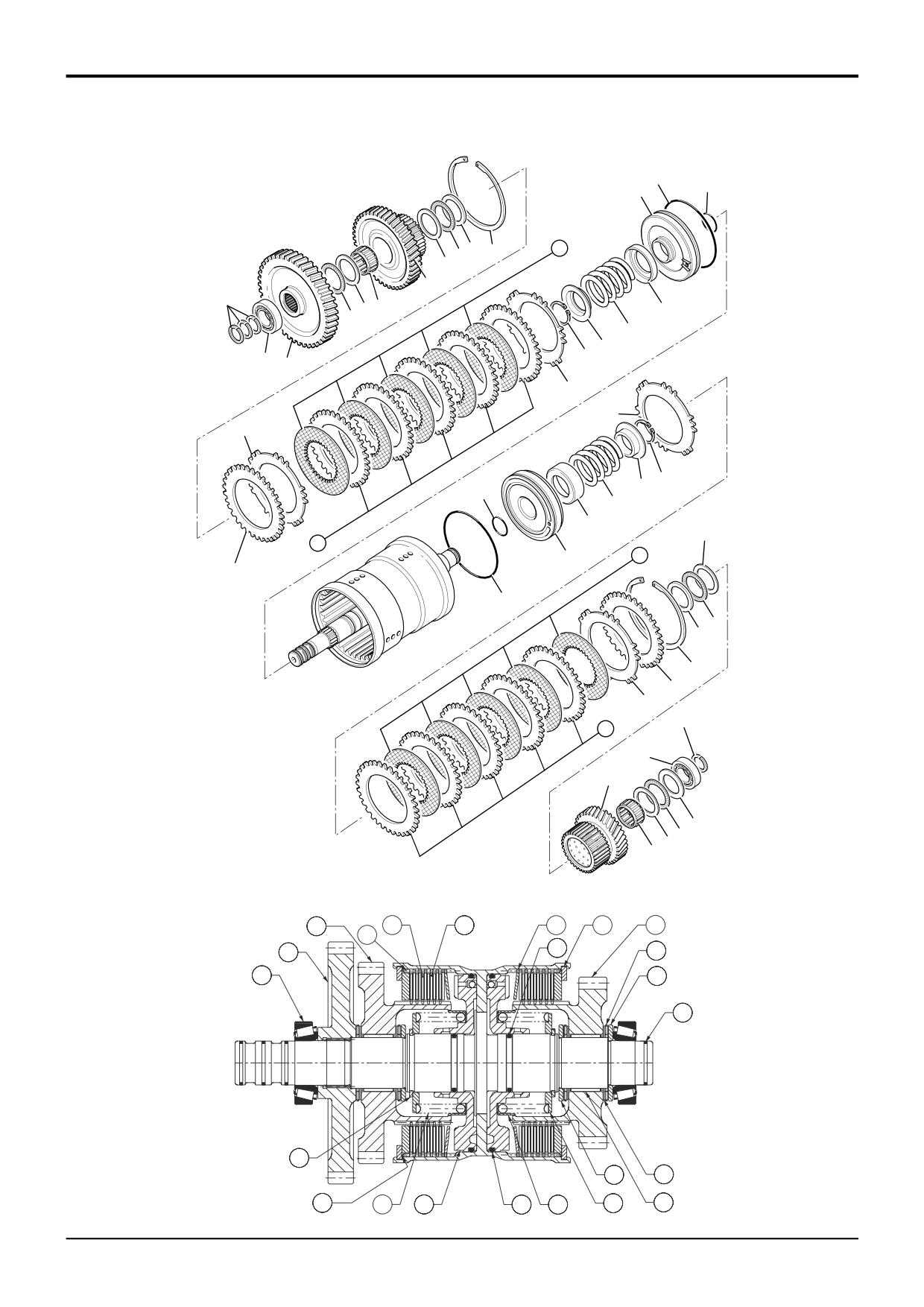
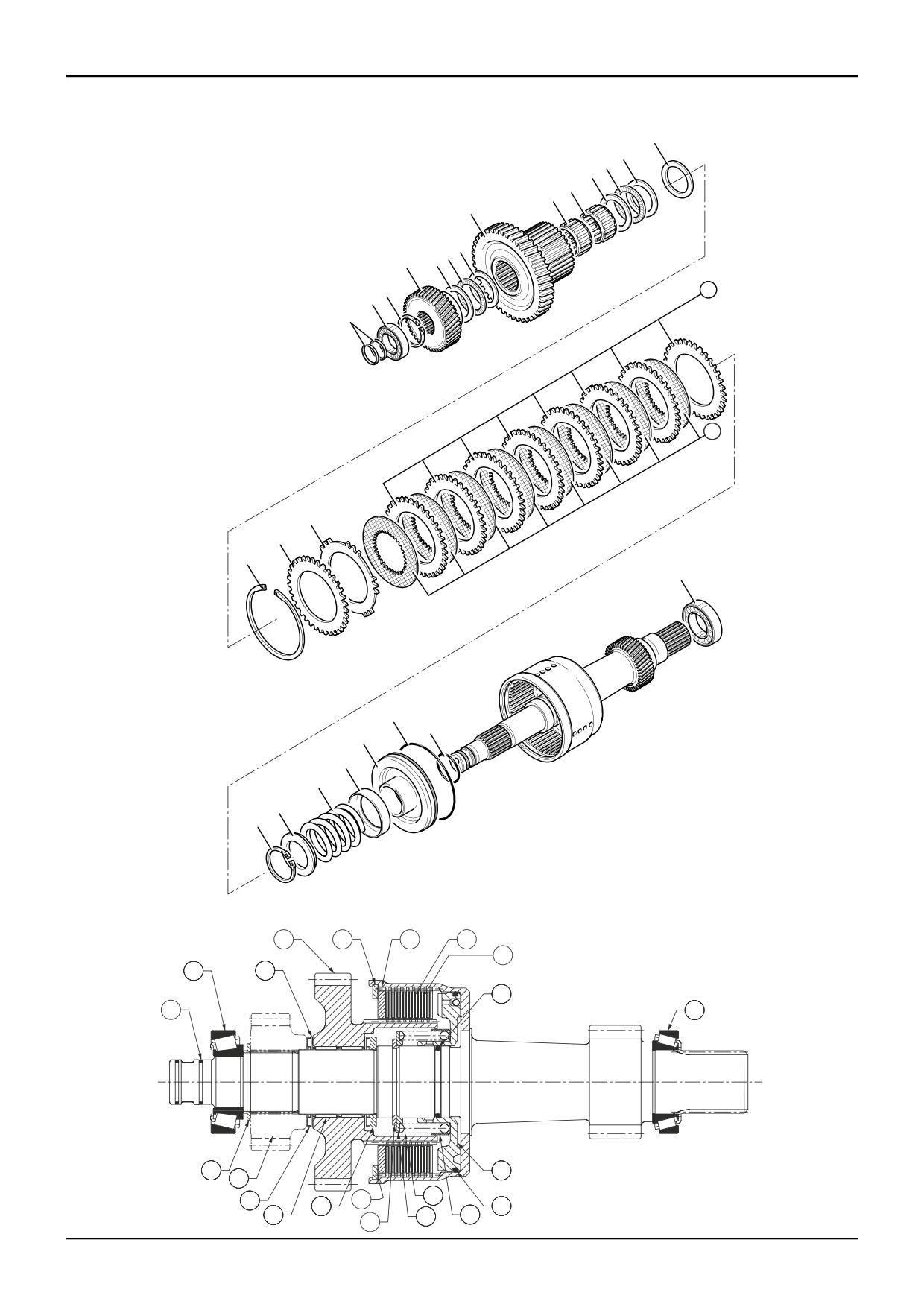
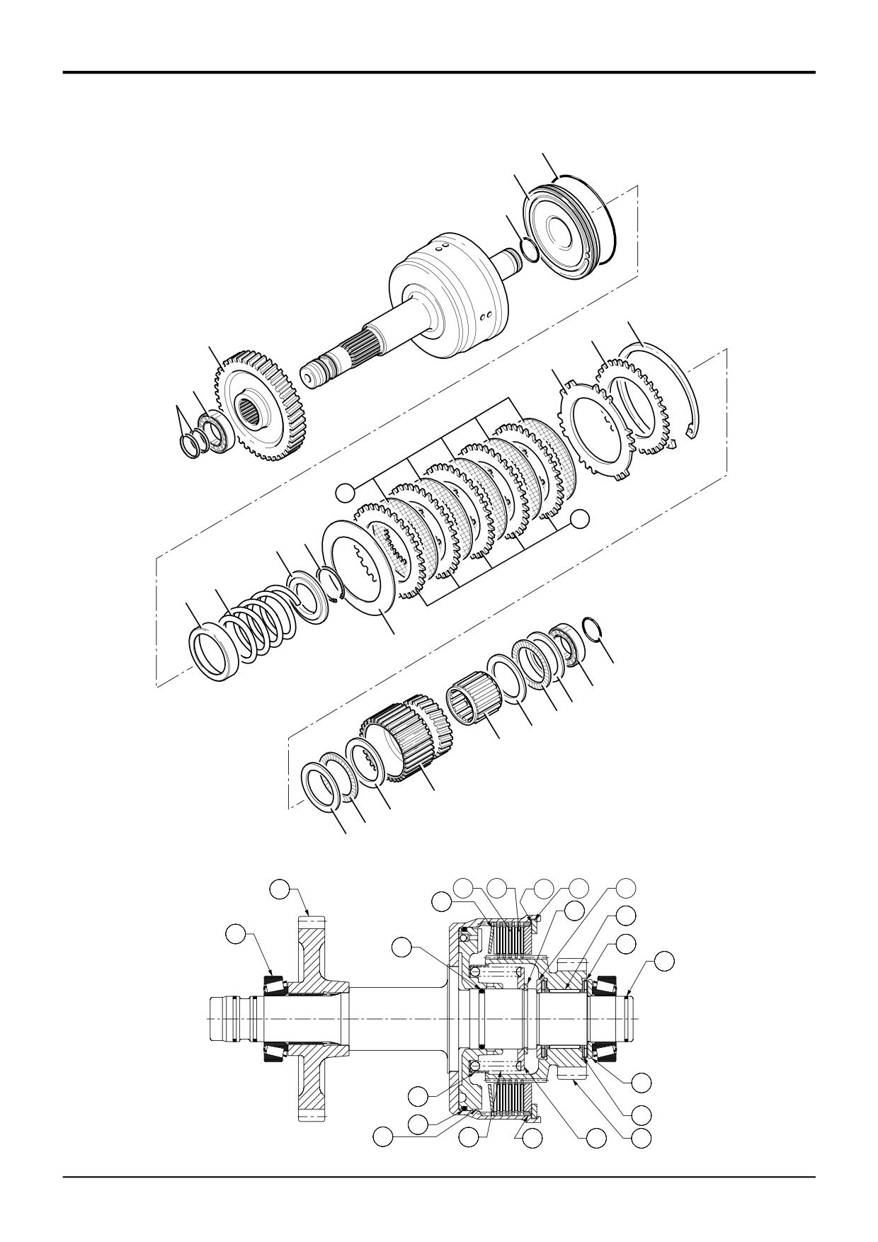
PS 760 - Forward/Input & Reverser Clutch - Dismantling
22
23
21
8
11
14
9
10
6
1
5
7
20
4
19
18
17
2
3
16
16
13
17
18
23
19
20
8
15
21
14
12
22
9
10
11
12
13
24
15
25
29
26
27
28
30
A396140
6
14
15
16
11
29
12
3
23
27
2
26
24
17
10
28
13
19
21
22
20
18
30
A396270
9803/3280
Issue 2*
Section F
Transmission
Section F
130 - 2
Powershift Gearbox
130 - 2
PS 760 - Forward/Input & Reverser Clutch - Dismantling
Note: The illustration shows a reverser shaft assembly for
11
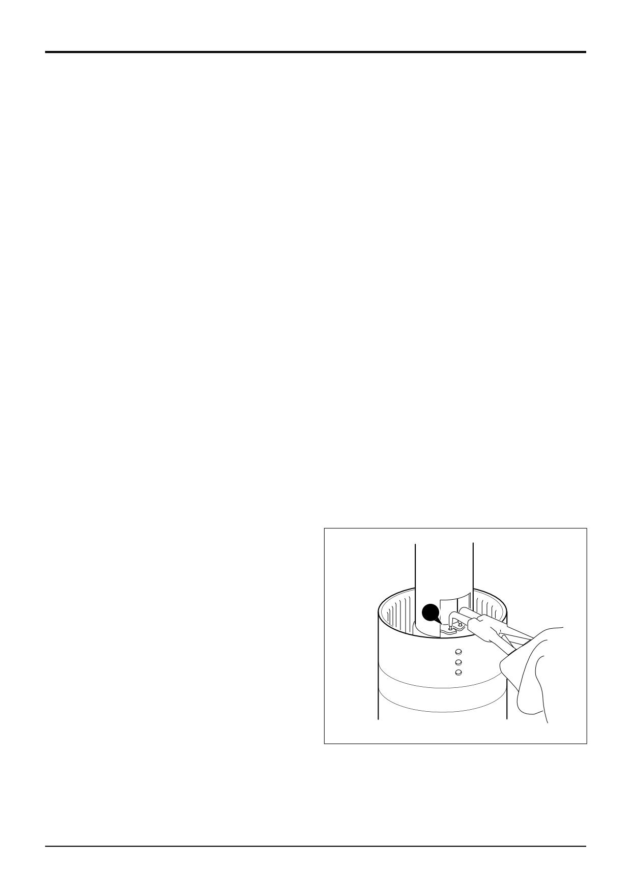
Lift off spring retaining plate 18.
the 6 - speed transmission. The input shaft assembly has
some small differences. An explanation of the differences will
12
Remove spring 19 and oil baffle 20.
be given as they occure in the procedure. The input and
reverser shaft assemblies for the 6 - speed transmission and
13
Turn the assembly over and knock the clutch shaft on a
the 4 - speed transmission are the same basic construction,
piece of aluminium (or wood) to loosen the piston 21.
except the
4
- speed transmission have fewer
friction/counter plates.
Note: If the piston does not loosen when the clutch shaft is
knocked on aluminium, then hand pump air down the shaft
1
Carefully remove piston ring seals 1. The input shaft
oil inlet hole.
does not have piston ring seals fitted at this end of the
shaft.
14
Remove the piston 21. Remove and discard the piston
‘O’ ring 22 and shaft ‘O’ ring 23.
Note: If the piston ring seals are excessively worn then
check for burrs or damage on the shaft grooves. If necessary
15
To dismantle the opposite clutch, carefully remove
remove burrs with a fine grade abrasion paper and oil.
piston ring seal 24. The input shaft has four piston ring
seals fitted at this end of the shaft.
2
Remove the clutch end bearing 2 and gear 3, using a
puller or press.
16
Loosen the clutch end bearing 25 and remove using a
puller.
3
Remove the thrust bearing 4 and thin thrust washer 5.
17
Remove thrust bearing 27 and thick and thin thru
4
Withdraw the gear and splined hub 6 with the needle
washers 26 and 28.
roller bearing 7.
18
Withdraw the gear and splined hub 29 with the need
5
Remove thrust bearing 9 and thick and thin thrust
roller bearing 30.
washers 8 and 10.
19
Repeat steps 5 to 14 to dismantle the clutch assembl
6
Remove the friction/counter plates retaining circlip 11.
7
Remove pressure end plate 13 and shim 12, if fitted.
8
Remove the friction plates 14 and counter plates 15.
Keep them together in sets, DO NOT mix the plates with
those from other clutches.
9
Remove disc spring assembly 16.
10
Position clutch assembly in a suitable press, with a cut
away tube compress the piston spring then remove
circlip 17.
17
A401360
9803/3280
Issue 1
Section F
Transmission
Section F
130 - 3
Powershift Gearbox
130 - 3
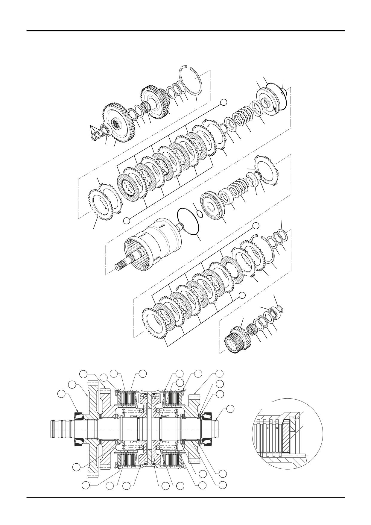
PS 760 - Forward/Input & Reverser Clutch - Assembly
22
23
21
8
11
14
9
10
6
1
5
7
20
4
19
18
17
2
3
16
16
13
17
18
23
19
20
8
15
21
14
12
22
9
10
11
12
13
24
15
25
29
26
27
28
30
A396140
6
14
15
16
11
29
12
3
23
27
2
26
24
A
11
13
17
A402700
10
28
13
19
21
22
20
18
30
A396270
9803/3280
Issue 3*
Section F
Transmission
Section F
130 - 4
Powershift Gearbox
130 - 4
PS 760 - Forward/Input & Reverser Clutch - Assembly
Visually inspect the friction and counter plates:
Counter plates - light scoring/polishing is permissible,
9
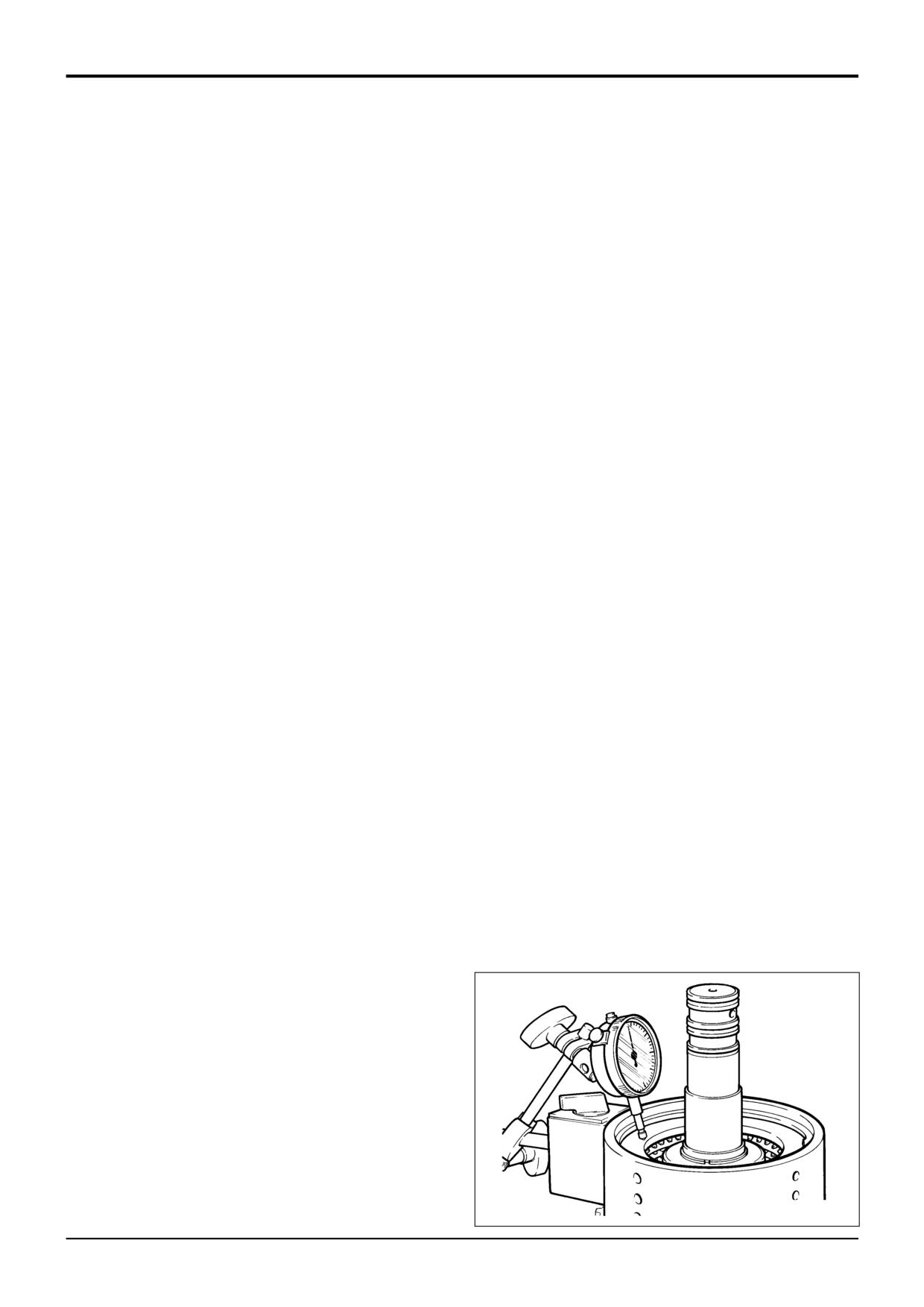
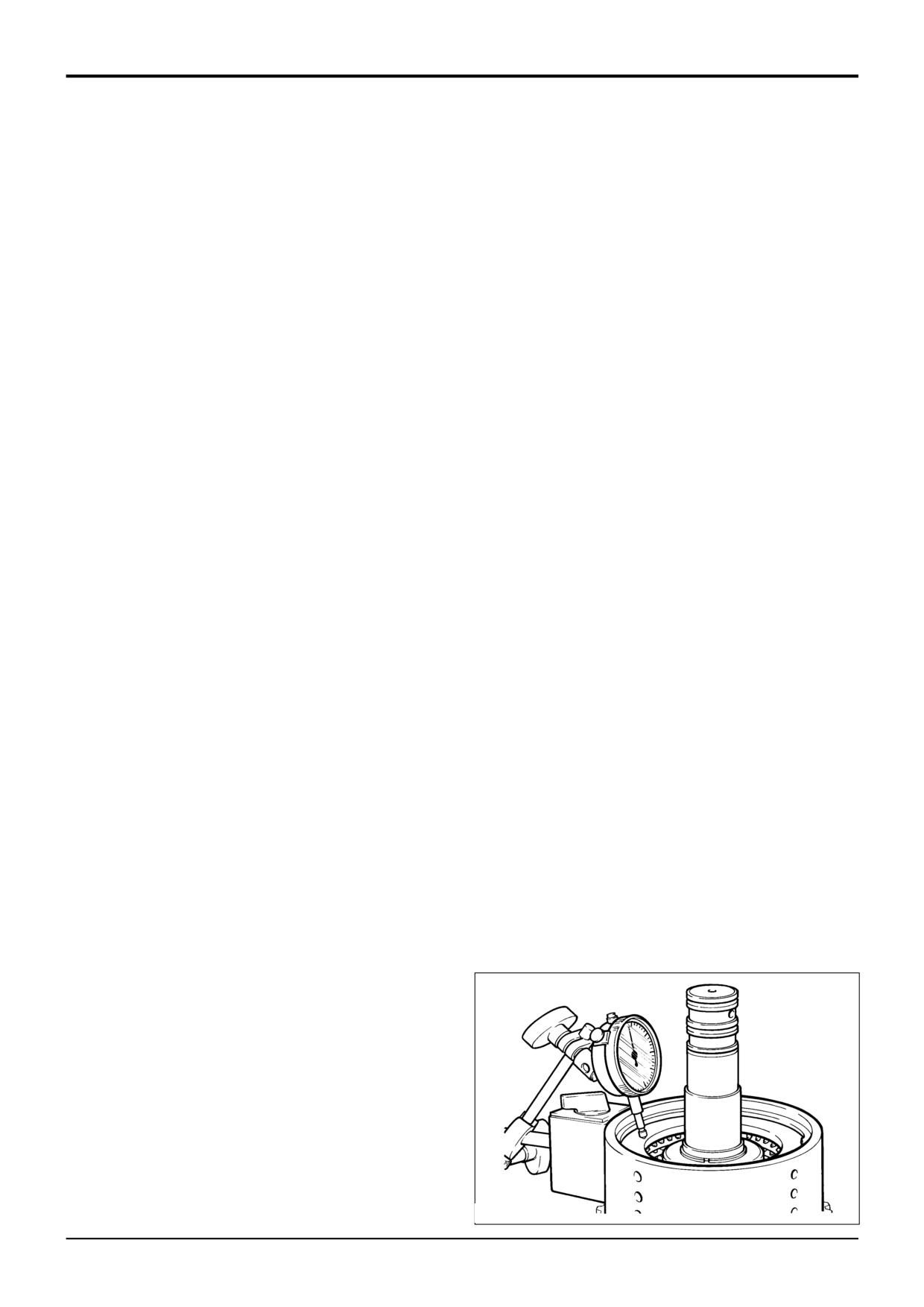
Using a dial test indicator as shown, measure the end
float of the pressure end plate 13, which should be 1.90
plates that are not flat, worn or heavily marked or scored
to 2.50 mm (0.075 to 0.098 in).
must be replaced with a new set.
If it is necessary to adjust the end float to bring it within
Friction plates - the cross hatching should be clearly
tolerance, there is a choice of fitting a 6.0mm (0.23in) or
visible, plates that are not flat, have friction material
6.5mm (0.25in) thick pressure end plate 13, with either a
damage or scoring must be replaced with a new set.
shim 12 or an extra counter plate 15 between the
retaining circlip 11 and pressure end plate 12.
DO NOT mix old and new plates, if a plate is damaged/worn
Use an airline to check the operation of the clutch.
fit a complete new set.
10
Fit thick and thin thrust washers 8 and 10, and thrust
Needle roller bearings should slide into position freely, do not
bearing 9.
bend or distort the cage to fit. If the cage has been distorted
11
Carefully align the teeth of the clutch plates using a thin
fit new bearings.
rod (or screwdriver) and fit the gear and splined hub 6.
Take care when handling disc spring assemblies 16 to avoid
12
Fit needle roller bearing 7.
marking or damage, which could result in stress cracking. If
in doubt fit a new disc spring.
13
Fit thrust bearing 4 and thin thrust washer 5.
Note: The piston incorporates a small check valve. Visually
14
Smear the clutch end bearing with gearbox oil and
inspect the piston to ensure the ball is in place and that the
press the gear 3 and bearing 2 onto the shaft.
seat is free from contamination. If necessary clean the valve
by blowing through with an air line. DO NOT use a wire rod
15
Fit piston ring seals 1, refer to Piston Ring Seals -
(or screwdriver) as damage to the valve seat could occur.
Fitting Procedure. The input shaft does not have
piston ring seals fitted at this end of the shaft.
1
Fit new 'O' rings 23 and 22. Lubricate the piston 21 with
oil and press fully into bore of clutch housing.
16
To assemble the opposite clutch repeat steps 1 to 10.
2
Fit the oil baffle 20, piston spring 19, make sure the
17
Carefully align the teeth of the clutch plates using a thin
spring seats in the piston.
rod (or screwdriver) and fit the gear and splined hub 29.
3
Fit the spring retaining plate 18.
18
Fit needle roller bearing 30.
4
Compress the spring and secure with circlip 17.
19
Fit thrust bearing 27 and thick and thin thrust washers
26 and 28.
5
Fit the disc spring assembly 16. Make sure that the disc
spring is fitted with the teeth towards the clutch pack.
20
Smear the clutch end bearing with gearbox oil and
Make sure the teeth are not aligned with the lubrication
press bearing 25 onto the shaft.
slots in the housing.
21
Fit piston ring seal 24, refer to Piston Ring Seals -
6
Fit one counter plate 15, followed by one friction plate
Fitting Procedure. The input shaft has four piston ring
14. Continue fitting alternate counter and friction plates,
seals fitted at this end of the shaft.
finishing with a friction plate.
7
Fit the pressure end plate 13. Make sure that the
*
chamfered face is fitted facing the clutch pack as
shown at A. Make sure the teeth are not aligned with
the lubrication slots in the housing. Do not fit shim 12 at
this stage.
8
Fit the clutch friction/counter plates retaining circlip 11.
S217590
9803/3280
Issue 2*
Section F
Transmission
Section F
131 - 1
Powershift Gearbox
131 - 1
11
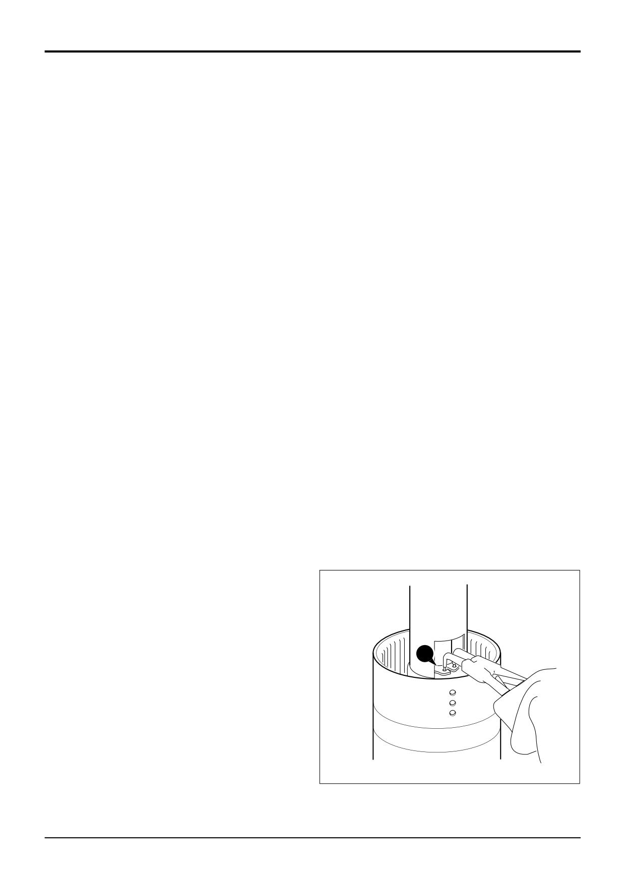
PS760 - Layshaft Clutch - Dismantling
9A
10
9
8
8
5
6
7
4
6
3
17
2
1
16
14
15
13
12
23
24
22
21
20
19
18
A396160
5
13
14
16
17
2
6
24
1
12
3
22
4
7
15
20
11
23
8
19
21
A396230
18
9803/3280
Issue 2*
Section F
Transmission
Section F
131 - 2
Powershift Gearbox
131 - 2
PS760 - Layshaft Clutch - Dismantling
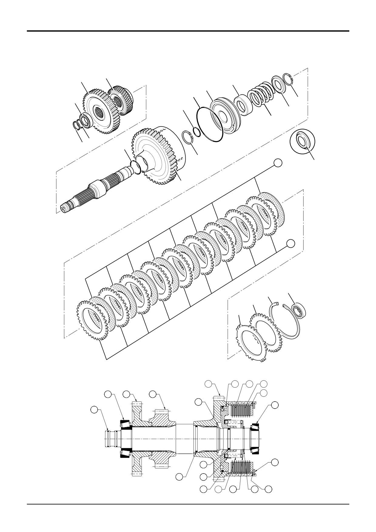
Note: The illustration shows a layshaft assembly for a 6 -
12
Lift off spring retaining plate 19.
speed transmission. The layshaft assembly for a 4 - speed
transmission has some small differences. An explanation of
13
Remove the spring 20 and oil baffle 21.
the differences will be given as they occure in the procedure.
14
Turn the assembly over and knock the clutch shaft on a
1
Carefully remove piston ring seals 1.
piece of aluminium (or wood) to loosen the piston 22.
Note: If the piston ring seals are excessively worn then
Note: If the piston does not loosen when the clutch shaft is
check for burrs or damage on shaft grooves. If necessary
knocked on aluminium, then hand pump air down the shaft
remove burrs with a fine grade abrasion paper and oil.
oil inlet hole.
2
Remove taper roller bearing 2 using a suitable puller or
15
Remove the piston 22. Remove and discard the piston
press.
'O' ring 23 and shaft 'O' ring 24.
3
Remove circlip 3 and withdraw the 4 wheel drive
transfer gear 4. Make a note which way round the gear
is fitted for assembly. The 2 wheel drive machines have
a spacer fitted instead of a gear.
4
Withdraw the gear and splined hub 5 together with thin
thrust washers 6 and thrust bearing 7.
5
Remove the two needle roller bearing assemblies 8.
4-speed transmissions have only one needle roller
bearing fitted.
6
Remove the thin thrust washer 9, thrust bearing 10, thin
*
thrust washer 9A (if fitted) and thick thrust washer 11.
7
If end bearing 12 is to be removed it must be renewed.
Remove the bearing using puller. Discard the bearing.
Note: This bearing would not normally be removed unless it
was damaged. If a collet tool is not available, then it is
permissible to use standard bearing puller, although damage
to the bearing cage may be incurred which will require a new
bearing.
8
Remove the clutch friction/counter plates retaining
circlip 13.
9
Remove pressure end plate 14 and shim 15, if fitted.
10
Remove the clutch friction plates 16 and counter plates
17. Keep them together in sets, DO NOT mix the plates
with those from other clutches.
11
Position clutch assembly in a suitable press, with a cut
18
away tube compress the piston spring as shown, then
remove circlip 18.
A401360
9803/3280
Issue 2*
Section F
Transmission
Section F
131 - 3
Powershift Gearbox
131 - 3
PS760 - Layshaft Clutch - Assembly
11A
11/11A
9A
10
9
8
5
6
7
4
6
3
B
5
9
9A
B
6
3
A405340
4
7
10
11
8
9803/3280
Issue 3*
Section F
Transmission
Section F
131 - 4
Powershift Gearbox
131 - 4
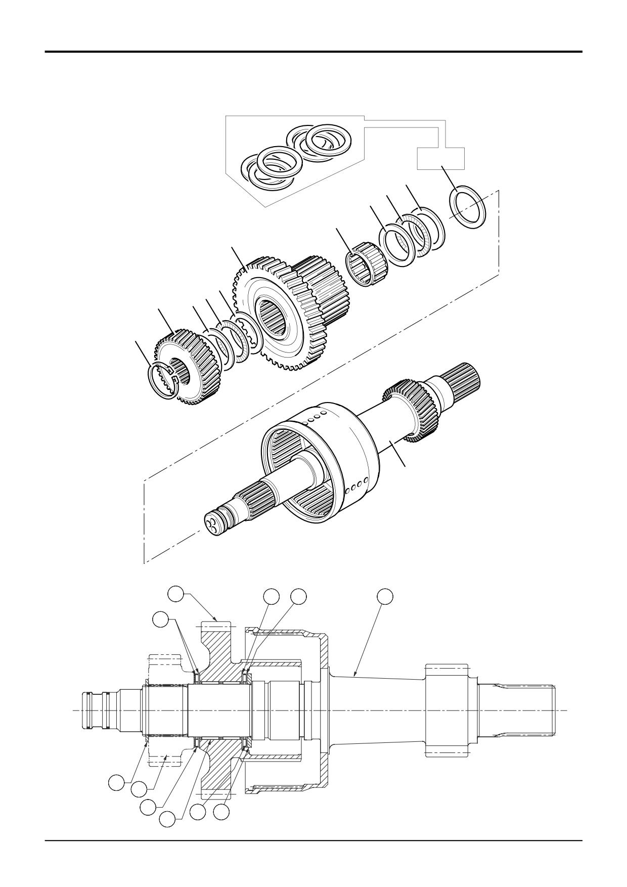
PS760 - Layshaft Clutch - Assembly
End Float Setting - Plate Carrier and Gear
(Only clutch assemblies fitted with thrust washer 9A)
Later clutch assemblies feature an additional thrust washer
9A. If any of the components listed below are to be renewed,
the end float of gear 5 must be measured and reset as
required:
Item
B Shaft assembly
5
Gear and plate carrier assembly
6,7
Thrust washer assembly
9,10 Thrust washer assembly
4
4WD transfer gear or spacer as applicable
Check and reset the endfloat of gear 5 as follows:
1
Temporarily fit thick thrust washer 11, thin thrust washer
9A, thrust bearing 10 and thin thrust washer 9. Fit
needle roller bearing 8.
2
Temporarily fit the gear and plate carrier assembly 5. Fit
the thin thrust washer 6 and thrust bearing 7 followed
by the remaining thrust washer 6.
3
Temporarily fit the 4 wheel drive transfer gear 4 onto the
layshaft spline. Make sure that the gear is fitted the
correct way round. 2 wheel drive machines have a
spacer fitted instead of a gear. Fit the circlip 3.
4
Make sure that the 4 wheel drive gear (or spacer) is fully
seated against circlip 3. Measure the end float of gear 5.
It must be between 0.01 to 0.15 mm (0.0004 to 0.006 in)
If the end float requires adjustment select a suitable
thrust washer from
11A and reassemble the
components as described above.
Note: 11A = kit 823/10420 - comprises 6 thrust washers of
the following thicknesses:
4.3 mm (0.169 in)
4.4 mm (0.173 in)
4.5 mm (0.177 in)
4.6 mm (0.181 in)
4.7 mm (0.185 in)
4.8 mm (0.189 in)
5
Recheck the end float and then dismantle the
components. Assemble the clutch as detailed on the
next page. Be sure to fit the correct thrust washer 11 on
final assembly.
9803/3280
Issue 3*
Section F
Transmission
Section F
131 - 5
Powershift Gearbox
131 - 5
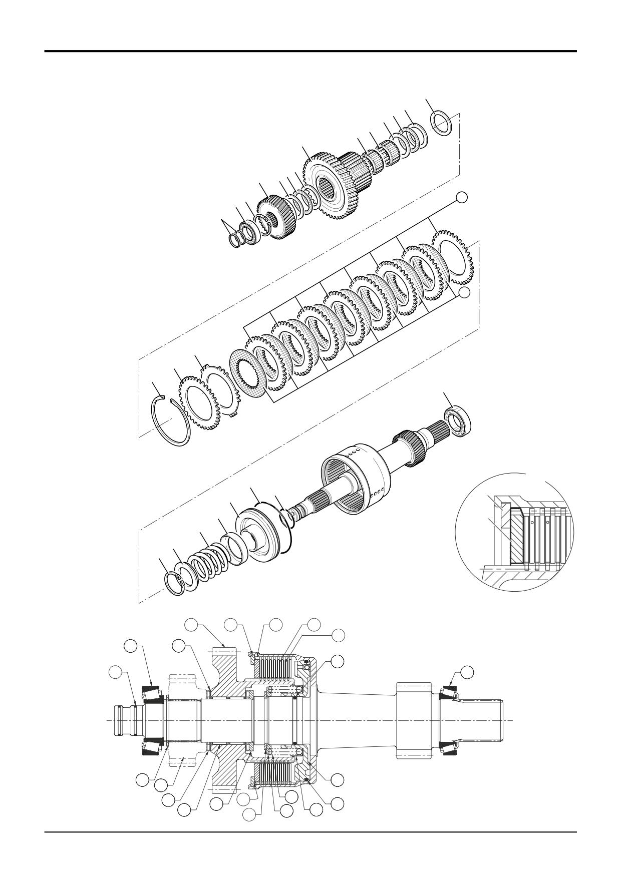
PS760 - Layshaft Clutch - Assembly
11
9A
10
9
8
8
5
6
7
4
6
3
17
2
1
16
14
15
13
12
23
A
24
22
13
21
14
20
19
18
A396160
5
13
14
16
17
2
6
24
1
12
3
22
4
7
15
20
11
23
8
19
21
A396230
18
9803/3280
Issue 1
Section F
Transmission
Section F
131 - 6
Powershift Gearbox
131 - 6
PS760 - Layshaft Clutch - Assembly
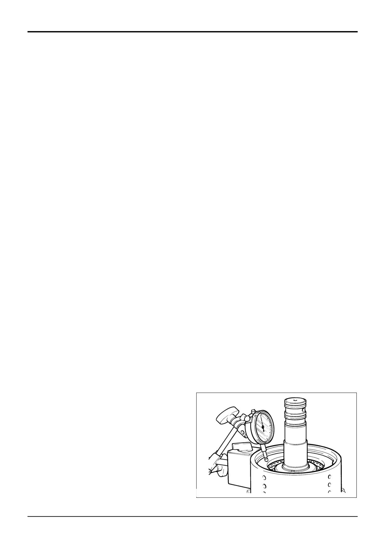
Visually inspect the friction and counter plates:
Counter plates - light scoring/polishing is permissible,
9
Fit the thick thrust washer 11, thin thrust washer 9A†,
*
thrust bearing 10 and thin thrust washer 9.
plates that are not flat, worn or heavily marked or scored
must be replaced with a new set.
† Thrust washer 9A not fitted to early clutch assemblies.
*
Friction plates - the cross hatching should be clearly
10
Fit the two needle roller bearings 8. The 4-speed
visible, plates that are not flat, have friction material
transmissions have only one needle roller bearing fitted.
damage or scoring must be replaced with a new set.
11
Carefully align the teeth of the clutch plates using a thin
DO NOT mix old and new plates, if a plate is damaged/worn
rod (or screwdriver) and fit the gear and splined hub 5.
fit a complete new set.
12
Fit the thin thrust washers 6 and thrust bearing 7.
Needle roller bearings should slide into position freely, do not
bend or distort the cage to fit. If the cage has been distorted
13
Fit the 4 wheel drive transfer gear 4 onto the layshaft
spline. Make sure that the gear is fitted the correct way
fit new bearings.
round. The 2 wheel drive machines have a spacer fitted
Note: The piston incorporates a small check valve. Visually
instead of a gear. Fit the circlip 3.
inspect the piston to ensure the ball is in place and that the
seat is free from contamination. If necessary clean the valve
14
Smear the clutch end bearings 2 and 12 with gearbox
by blowing through with an air line. DO NOT use a wire rod
oil. Oil and press the bearings onto the shaft.
(or screwdriver) as damage to the valve seat could occur.
15
Fit piston ring seals 1, refer to Piston Ring Seals -
Fitting Procedure.
1
Fit new 'O' rings 24 and 23. Lubricate the piston 22 with
oil and press fully into bore of clutch housing.
2
Fit oil baffle 21, piston spring 20, make sure the spring
seats in the piston.
3
Fit the spring retaining plate 19.
4
Compress the spring and secure with circlip 18.
5
Fit one counter plate 17 followed by one friction plate
16. Continue fitting alternate counter and friction plates,
finishing with a friction plate.
6
Fit the pressure end plate 14, do not fit shim 15 at this
stage. Make sure that the chamfered face is fitted
facing the clutch pack as shown at A. Make sure the
teeth are not aligned with the lubrication slots in the
housing.
Note: A spring disc is not fitted in this clutch pack.
7
Fit the clutch friction/counter plates retaining circlip 13.
8
Using a dial test indicator as shown, measure the end
float of the pressure end plate 14, which should be 1.9
to 2.5 mm (0.075 to 0.098 in).
If it is necessary to adjust the end float to bring it within
tolerance, there is a choice of fitting a 6.0mm (0.23in) or
6.5mm (0.25in) thick pressure end plate 14, with either
a shim 15 or an extra counter plate 17 between the
retaining circlip 13 and pressure end plate 14.
Use an airline to check the operation of the clutch.
217590
9803/3280
Issue 1
Section F
Transmission
Section F
132 - 1
Powershift Gearbox
132 - 1
PS760 - Mainshaft Clutch - Dismantling
4
3
14
15
16
2
11
17
12
13
1
1
20
18
9
12
(4-speed type)
19
10
5
6
7
8
A396150
19
15
10
9
2
3
4
7
18
5
1
6
17
20
14
16
13
12
11
8
A396250
9803/3280
Issue 1
Section F
Transmission
Section F
132 - 2
Powershift Gearbox
132 - 2
PS760 - Mainshaft Clutch - Dismantling
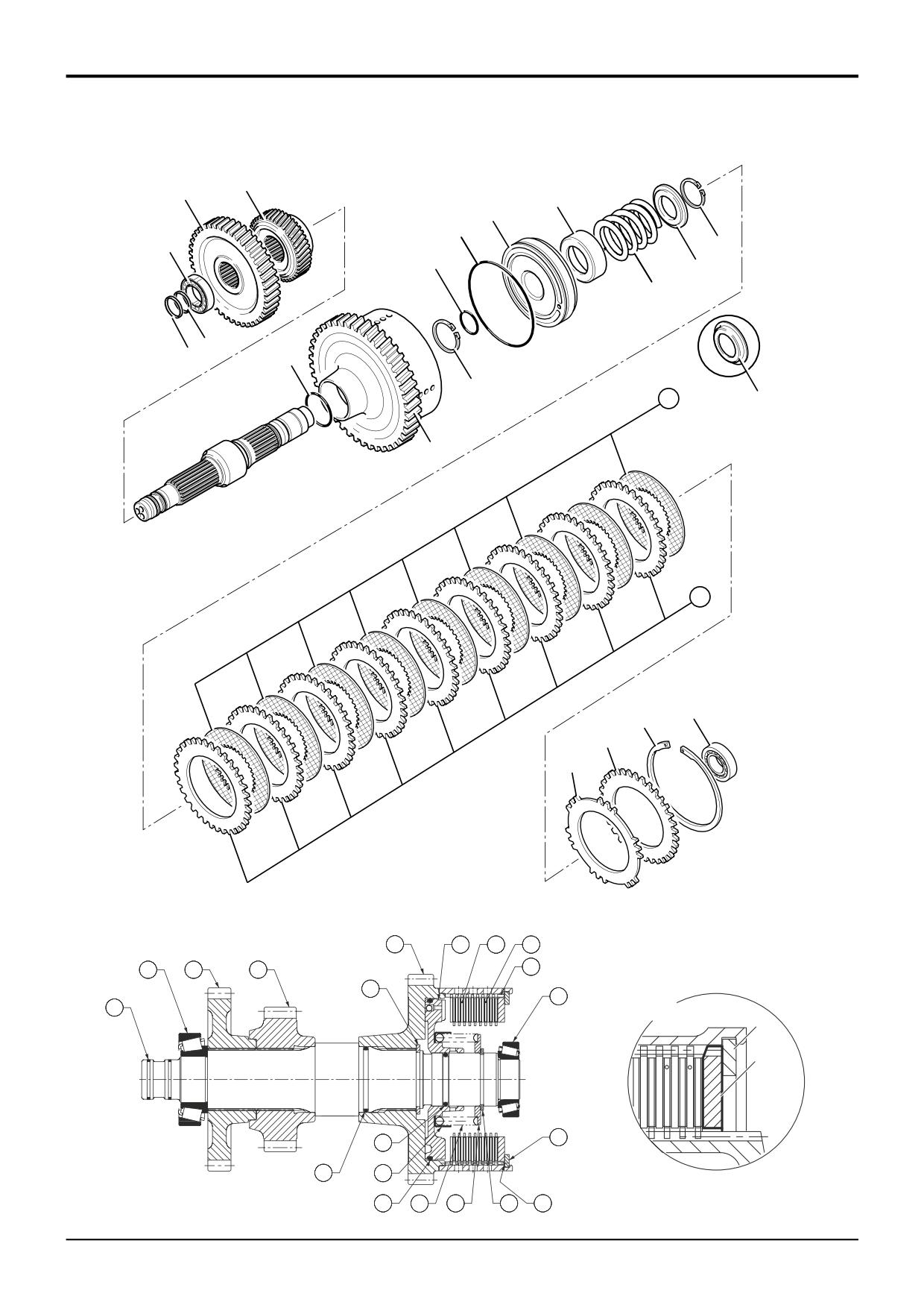
Note: The illustration shows a mainshaft assembly for a 6 -
9
Lift off spring retaining plate 12. The 4 - speed
speed transmission. The mainshaft assembly for a 4 - speed
transmissions have a different shaped spring retaining
transmission has some small differences. An explanation of
plate fitted.
the differences will be given as they occure in the procedure.
The mainshaft assemblies for the 6 - speed and the 4 -
10
Remove the spring 13 and oil baffle 14.
speed transmission are the same basic construction, except
the 4 - speed transmission have fewer friction/counter
11
Turn the assembly over and knock the clutch shaft on a
plates.
piece of aluminium (or wood) to loosen the piston 15.
1
Carefully remove piston ring seals 1.
Note: If the piston does not loosen when the clutch shaft is
knocked on aluminium, then hand pump air down the shaft
Note: If the piston ring seals are excessively worn then
oil inlet hole.
check for burrs or damage on shaft grooves. If necessary
remove burrs with a fine grade abrasion paper and oil.
12
Remove the piston 15. Remove and discard the piston
‘O’ ring 16 and shaft ‘O’ ring 17.
2
Remove taper roller bearing 2 using a puller or press.
13
Remove circlip 18 and withdraw the clutch housing 19
3
Withdraw the gears 3 and 4. Make a note which way
from the shaft. Remove and discard the ‘O’ ring 20.
round the gears are fitted for assembly.
4
At the opposite end, use a suitable puller to remove the
taper roller bearing 5.
5
Remove the clutch friction/counter plates retaining
circlip 6.
6
Remove the pressure end plate 7 and shim 8, if fitted.
7
Remove the clutch friction plates 9 and counter plates
10. Keep them together in sets, DO NOT mix the plates
with those from other clutches.
8
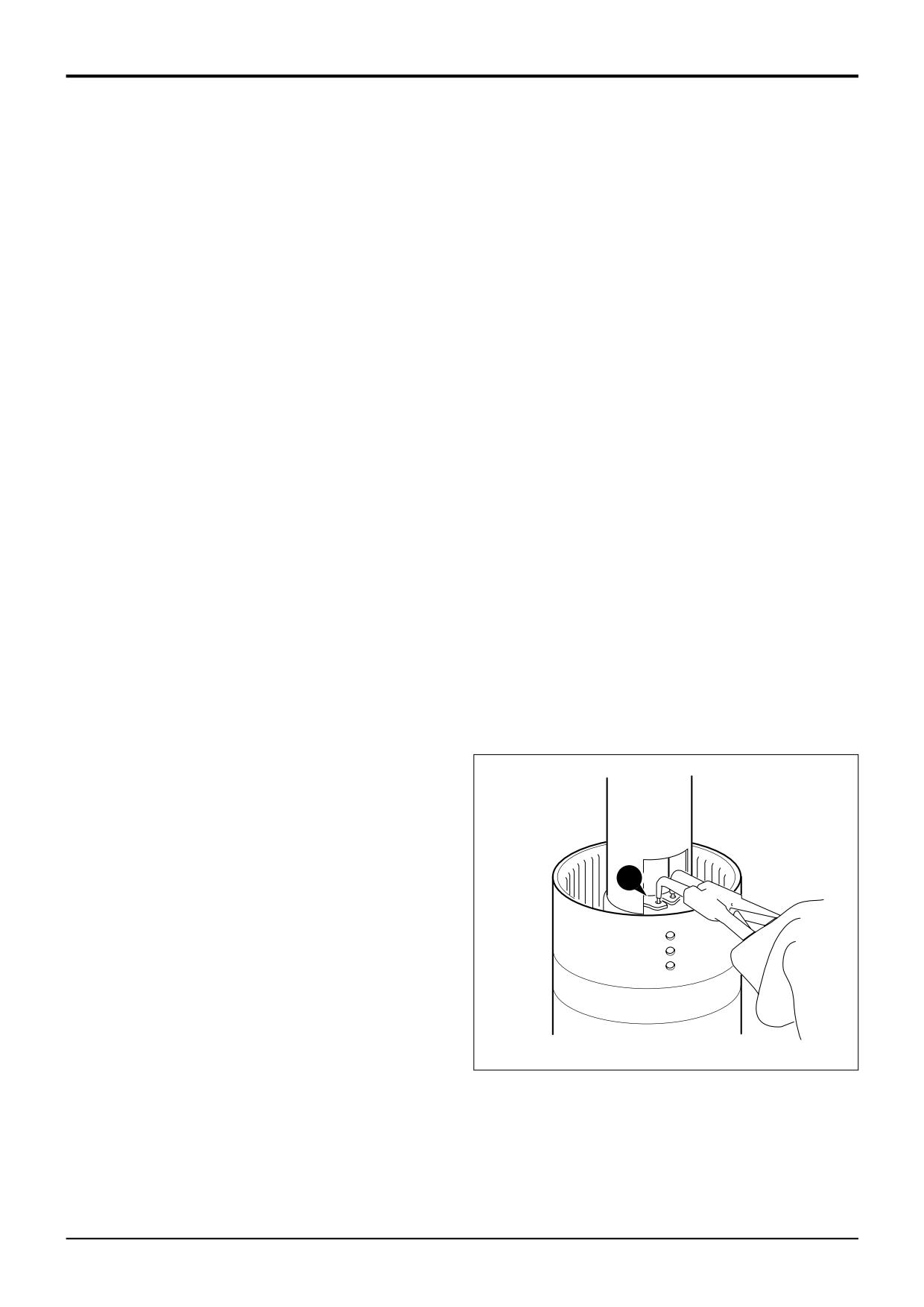
Position clutch assembly in a suitable press, with a cut
away tube compress the piston spring as shown, then
remove circlip 11.
11
A401360
9803/3280
Issue 1
Section F
Transmission
Section F
132 - 3
Powershift Gearbox
132 - 3
PS760 - Mainshaft Clutch - Assembly
4
3
14
15
16
2
11
17
12
13
1
1
20
18
9
12
(4-speed type)
19
10
5
6
7
8
A396150
19
15
10
9
2
3
4
7
18
5
1
A
6
8
6
17
A402700
20
14
16
13
12
11
8
A396250
9803/3280
Issue 2*
Section F
Transmission
Section F
132 - 4
Powershift Gearbox
132 - 4
PS760 - Mainshaft Clutch - Assembly
Visually inspect the friction and counter plates:
Use an airline to check the operation of the clutch.
Counter plates - light scoring/polishing is permissible,
11
Smear the taper roller bearing 5 with gearbox oil and
press the bearing onto the shaft.
plates that are not flat, worn or heavily marked or scored
must be replaced with a new set.
12
At the opposite end press gears 3 and 4 onto shaft
spline. Make sure that the gears are fitted the correct
Friction plates - the cross hatching should be clearly
way round.
visible, plates that are not flat, have friction material
damage or scoring must be replaced with a new set.
13
Smear the taper roller bearing 2 with gearbox oil and
press the bearing onto the shaft.
DO NOT mix old and new plates, if a plate is damaged/worn
fit a complete new set.
14
Fit piston ring seals 1, refer to Piston Ring Seals -
Fitting Procedure.
Needle roller bearings should slide into position freely, do not
bend or distort the cage to fit. If the cage has been distorted
fit new bearings.
Note: The piston incorporates a small check valve. Visually
inspect the piston to ensure the ball is in place and that the
seat is free from contamination. If necessary clean the valve
by blowing through with an air line. DO NOT use a wire rod
(or screwdriver) as damage to the valve seat could occur.
1
Fit a new ‘O’ ring 20.
2
Press the clutch housing 19 onto the shaft spline and fit
circlip 18.
3
Fit a new 'O' rings 17 and 16. Lubricate the piston 15
with oil and press fully into bore of clutch housing.
4
Fit oil baffle 14, piston spring 13, make sure the spring
seats in the piston.
5
Fit the spring retaining plate 12. The 4 - speed
transmissions have a different shaped spring retaining
plate fitted.
6
Compress the spring and secure with circlip 11.
7
Fit one counter plate 8 followed by one friction plate 9.
Continue fitting alternate counter and friction plates,
finishing with a friction plate.
* 8
Fit pressure end plate 7. Make sure that the chamfered
face is fitted facing the clutch pack as shown at A.
Make sure the teeth are not aligned with the lubrication
slots in the housing. Do not fit shim 7 at this stage.
Note: A spring disc is not fitted in this clutch pack.
9
Fit the clutch friction/counter plate retaining circlip 6.
10
Using a dial test indicator as shown, measure the end
float of the pressure end plate 7, which should be 1.9 to
2.5 mm (0.075 to 0.098 in).
If it is necessary to adjust the end float to bring it within
tolerance, there is a choice of fitting a 6.0mm (0.23in) or
6.5mm (0.25in) thick pressure end plate 7, with either a
shim 8 or an extra counter plate 10 between the
217590
retaining circlip 6 and pressure end plate 7.
9803/3280
Issue 2*
Section F
Transmission
Section F
133- 1
Powershift Gearbox
133 - 1
PS760 - 6 Speed Clutch - Dismantling
24
23
25
13
15
3
14
2
1
16
17
19
20
21
22
18
1
4
6
7
8
9
5
10
11
12
A396170
3
16
17
15
13
12
18
19
9
2
25
7
1
6
22
8
24
23
21
14
20
5
A396240
9803/3280
Issue 1
Section F
Transmission
Section F
133- 2
Powershift Gearbox
133 - 2
PS760 - 6 Speed Clutch - Dismantling
1
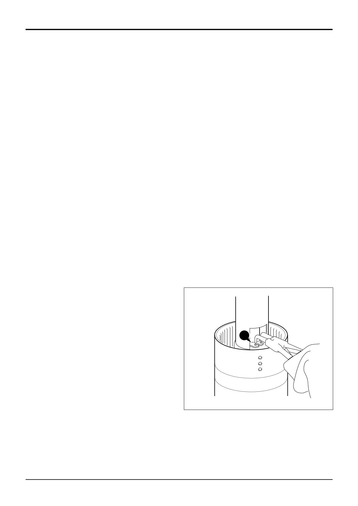
Carefully remove piston ring seals 1 at each end of the
shaft.
13
Lift off spring retaining plate 20.
Note: If the piston ring seals are excessively worn then
14
Remove the spring 21 and oil baffle 22.
check for burrs or damage on shaft grooves. If necessary
remove burrs with a fine grade abrasion paper and oil.
15
Turn the assembly over and knock the clutch shaft on a
piece of aluminium (or wood) to loosen the piston 23.
2
Remove taper roller bearing 2 using a collet tool and
press.
Note: If the piston does not loosen when the clutch shaft is
knocked on aluminium, then hand pump air down the shaft
3
Withdraw the gear 3. Make a note which way round the
oil inlet hole.
gear is fitted for assembly.
14
Remove the piston 23. Remove and discard the piston
4
At the opposite end, remove the clutch end bearing 4
'O' ring 24 and shaft 'O' ring 25.
using a puller.
5
Withdraw the gear and splined hub 5 together with thick
thrust washer 6, thrust bearing 7 and thin thrust washer
8.
6
Remove the needle roller bearing 9.
7
Remove the thin thrust washer 10, thrust bearing 11
and thick thrust washer 12.
8
Remove the clutch friction/counter plates retaining
circlip 13.
9
Remove pressure end plate 14 and shim 15, if fitted.
10
Remove the clutch friction plates 16 and counter plates
17. Keep them together in sets, DO NOT mix the plates
with those from other clutches.
11
Remove the disc spring assembly 18.
12
Position clutch assembly in a suitable press, with a cut
away tube compress the piston spring as shown, then
remove circlip 19.
19
A401360
9803/3280
Issue 1
Section F
Transmission
Section F
133- 3
Powershift Gearbox
133 - 3
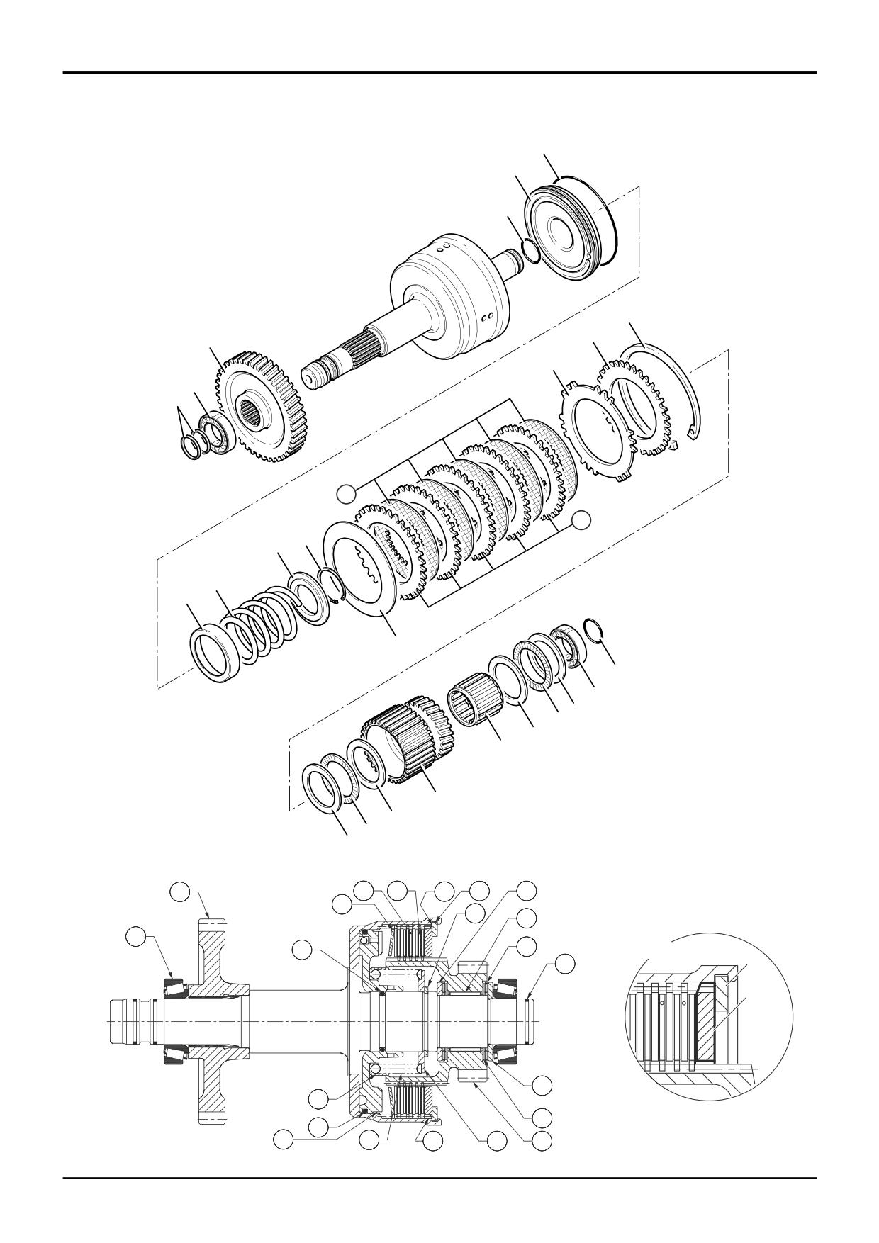
PS760 - 6 Speed Clutch - Assembly
24
23
25
13
3
15
14
2
1
16
17
19
20
21
22
18
1
4
6
7
8
9
5
10
11
12
A396170
3
16
17
15
13
12
18
19
9
2
25
7
A
1
13
14
6
22
A402700
8
24
23
21
14
20
5
A396240
9803/3280
Issue 2*
Section F
Transmission
Section F
133- 4
Powershift Gearbox
133 - 4
PS760 - 6 Speed Clutch - Assembly
Visually inspect the friction and counter plates:
9
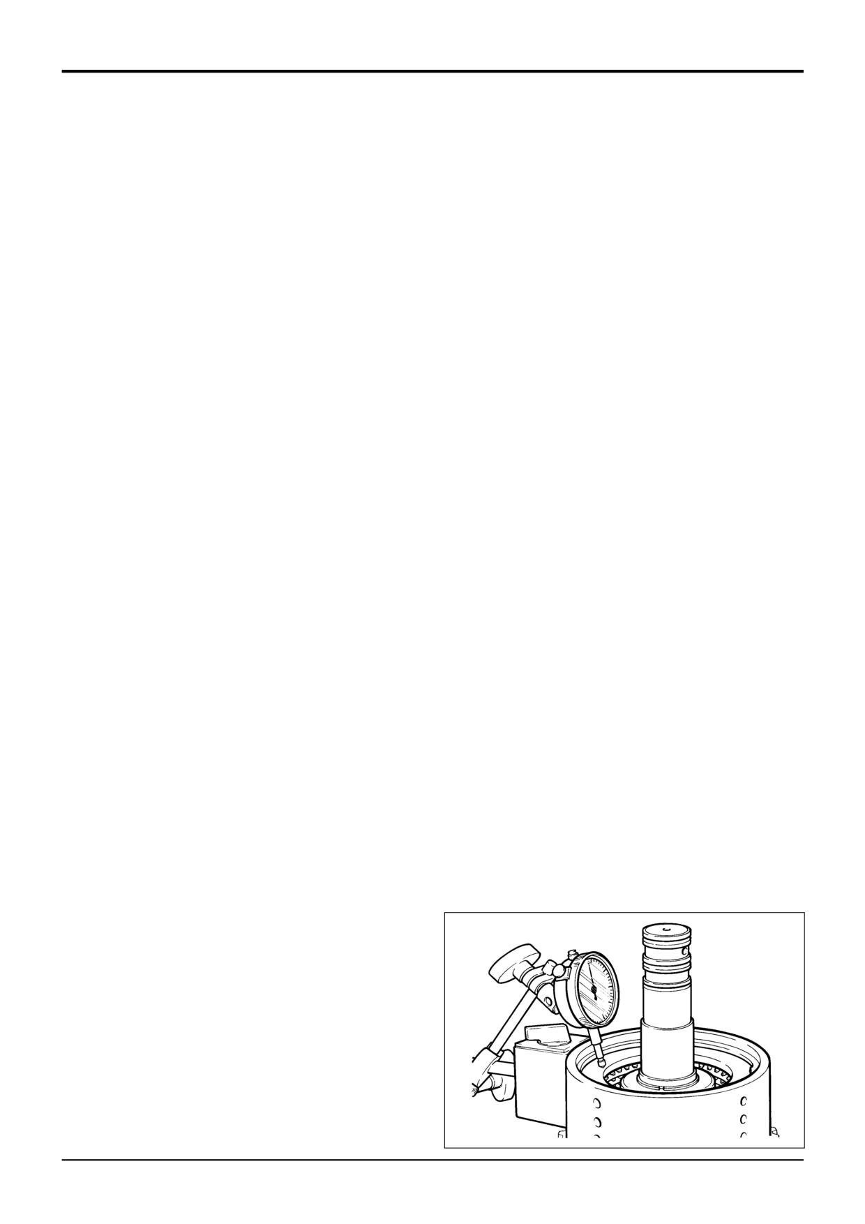
Using a dial test indicator as shown, measure the end
float of the pressure end plate 14, which should be 1.9
Counter plates - light scoring/polishing is permissible,
to 2.5 mm (0.075 to 0.098 in).
plates that are not flat, worn or heavily marked or scored
If it is necessary to adjust the end float to bring it within
must be replaced with a new set.
tolerance, there is a choice of fitting a 6.0mm (0.23in) or
6.5mm (0.25in) thick pressure end plate 14, with either
Friction plates - the cross hatching should be clearly
a shim 15 or an extra counter plate 17 between the
visible, plates that are not flat, have friction material
retaining circlip 13 and pressure end plate 14.Use an
damage or scoring must be replaced with a new set.
airline to check the operation of the clutch.
DO NOT mix old and new plates, if a plate is damaged/worn
10
Fit the thick thrust washer 12, thrust bearing 11 and thin
fit a complete new set.
thrust washer 10.
Needle roller bearings should slide into position freely, do not
11
Fit the needle roller bearing 9.
bend or distort the cage to fit. If the cage has been distorted
12
Carefully align the teeth of the clutch plates using a thin
fit new bearings.
rod (or screwdriver) and fit the gear and splined hub 5.
Take care when handling disc spring assemblies 18 to avoid
13
Fit the thin thrust washer 8, thrust bearing 7 and thick
marking or damage, which could result in stress cracking. If
thrust washer 6.
in doubt fit a new disc spring.
14
Smear the clutch end bearing 4 with gearbox oil and
Note: The piston incorporates a small check valve. Visually
press the bearing onto the shaft.
inspect the piston to ensure the ball is in place and that the
seat is free from contamination. If necessary clean the valve
15
At the opposite end, press the gear 3 onto the shaft
by blowing through with an air line. DO NOT use a wire rod
spline. Make sure that the gear is fitted the correct way
(or screwdriver) as damage to the valve seat could occur.
round.
1
Fit new 'O' rings 25 and 24. Lubricate the piston 23 with
16
Smear the clutch end bearing 2 with gearbox oil and
oil and press fully into bore of clutch housing.
press the bearing onto the shaft.
2
Fit oil baffle 22, piston spring 21, make sure the spring
17
Fit piston ring seals 1 at each end of the shaft, refer to
seats in the piston.
Piston Ring Seals - Fitting Procedure.
3
Fit the spring retaining plate 20.
4
Compress the spring and secure with circlip 19.
5
Fit the disc spring assembly 18. Make sure that the disc
spring is fitted with the teeth towards the clutch pack.
Make sure the teeth are not aligned with the lubrication
slots in the housing.
6
Fit one counter plate 17 followed by one friction plate
16. Continue fitting alternate counter and friction plates,
finishing with a friction plate.
7
Fit the pressure end plate 14, do not fit shim 15 at this
*
stage. Make sure that the chamfered face is fitted
facing the clutch pack as shown at A. Make sure the
teeth are not aligned with the lubrication slots in the
housing.
8
Fit the clutch friction/counter plates retaining circlip 13.
217590
9803/3280
Issue 2*
Section F
Transmission
Section F
134 - 1
Powershift Gearbox
134 - 1
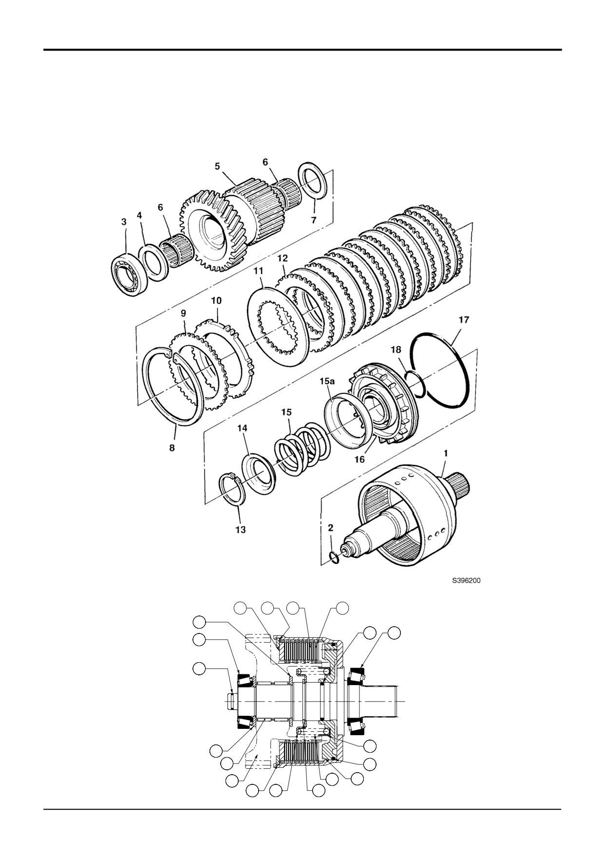
PS 760 - 2/4WD Clutch (Pressure ON) - Dismantling
10
9
12
11
7
18
1
3
2
15a
4
6
17
5
15
16
8
14
13
A396260
9803/3280
Issue 1