JCB 3CX, 4CX, 214e, 214, 215, 217 & VARIANTS Backhoe Loader. Service Manual - page 33
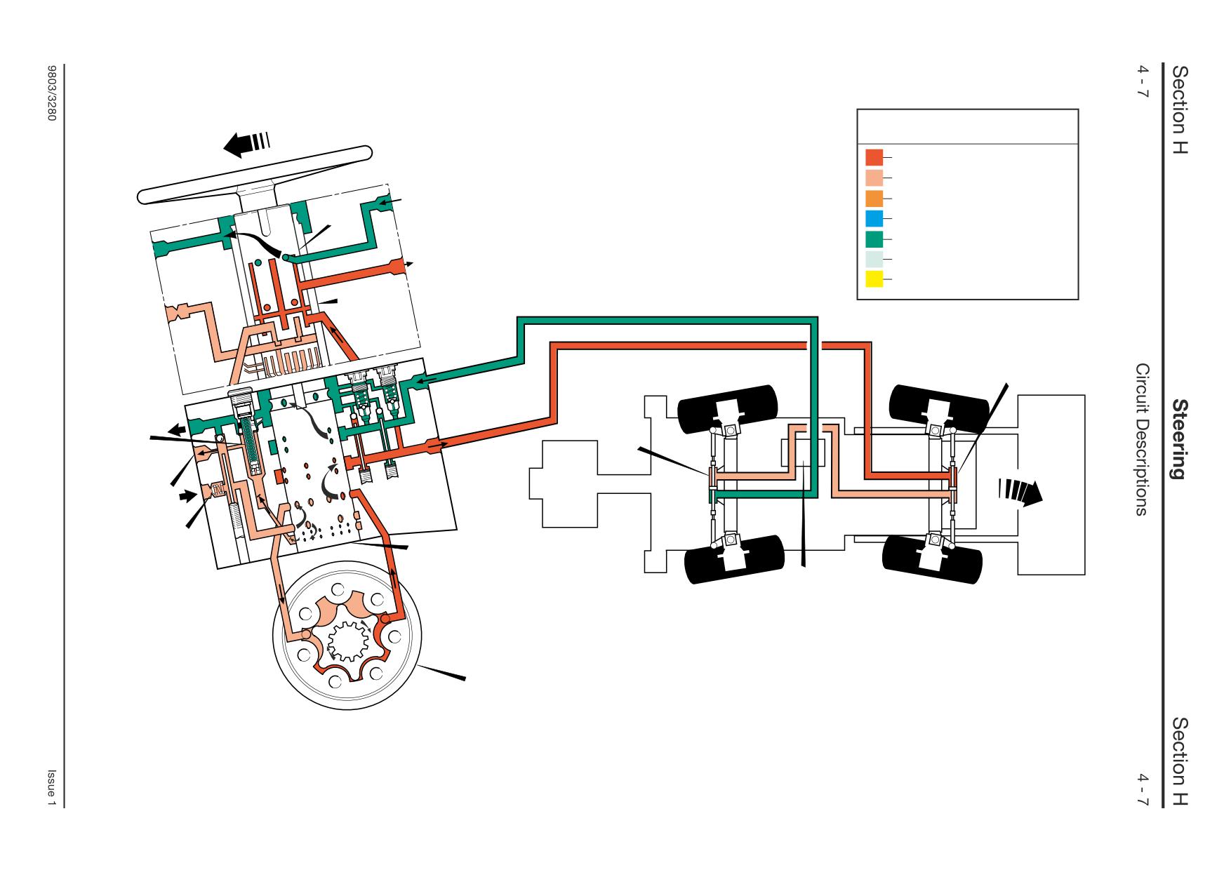
Key to Oil Flow & Pressure
Full Pressure
Pressure
Servo
A
Neutral
Exhaust
Cavitation
Lock Up
B
A390630
40
43B
41
LS
43C
B
X
D
A395660
Key to Oil Flow & Pressure
Full Pressure
Pressure
A
Servo
Neutral
Exhaust
Cavitation
Lock Up
B
A390630
40
41
F
B
X
D
A395670
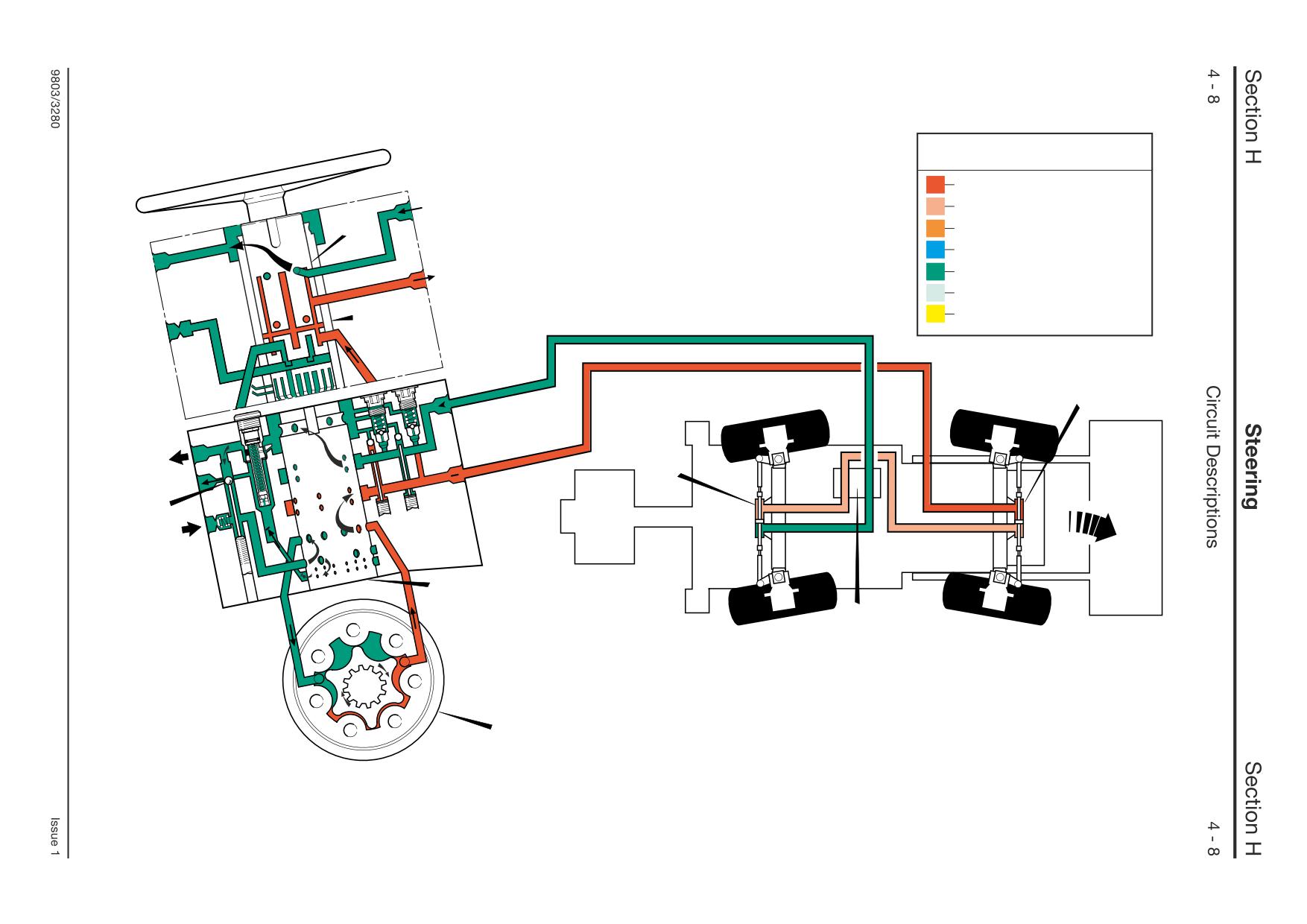
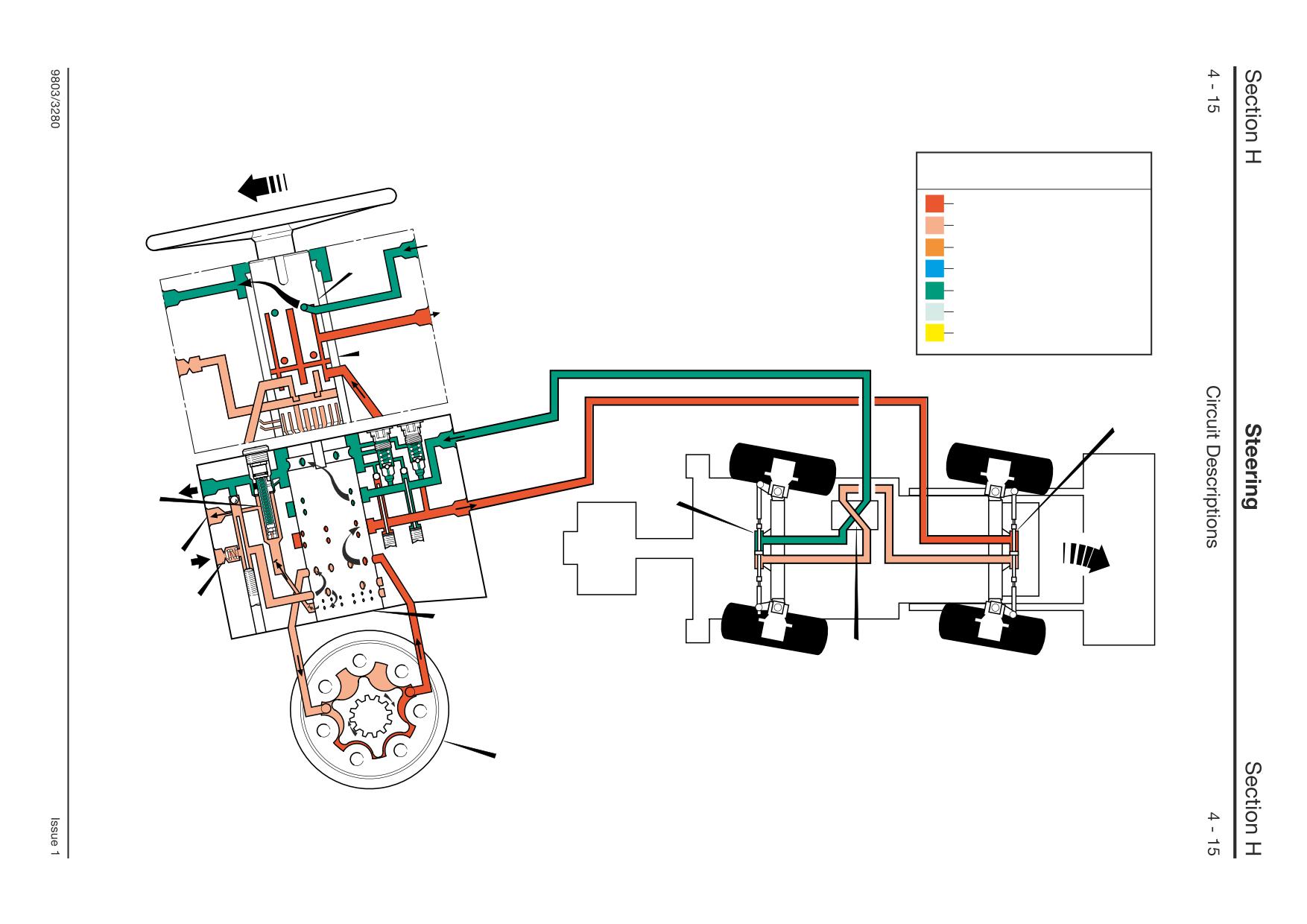
Steer Unit Operation
- 4 Wheel Steer Machines
4 Wheel Steer Mode
- Right Turn, Unassisted
The illustration shows the circuit operation with the
engine stopped. Turning the steering wheel rotates
the inner spool A until the cross pin engages with
and rotates outer sleeve B, metering oil to the
stator D, and pumping it out to power track rod
rams 40 and 41 under manual pressure only.
As there is no supply from the pump, oil from one
side of the power track rod rams, supplemented by
exhaust oil if necessary, is used to feed the other
side via non-return valve F.
Component Key:
A Inner Spool
B Outer Spool
D Stator
F Non-Return Valve
X Steer Mode Control Valve
40
Front Power Track Rod Ram
41
Rear Power Track Rod Ram
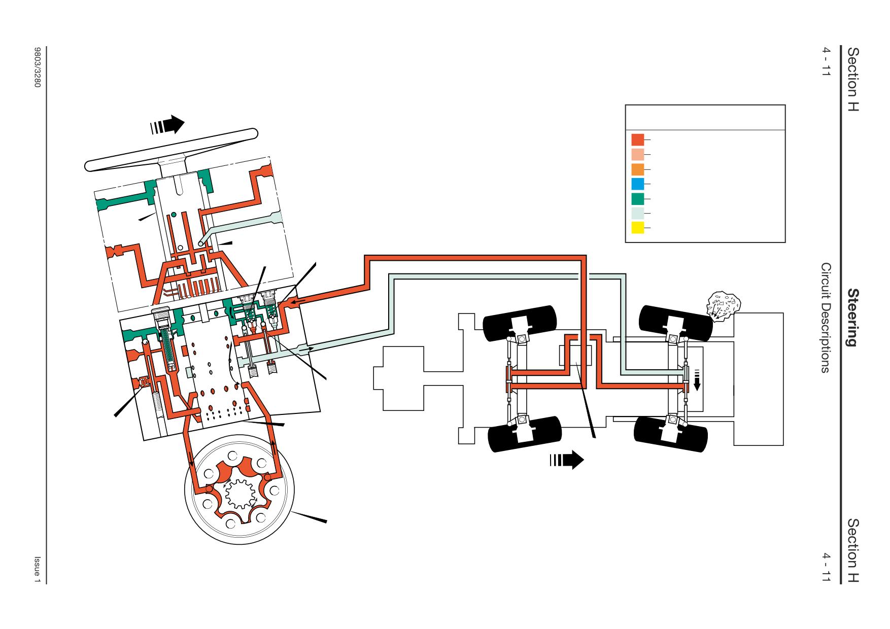
Steer Unit Operation
- 4 Wheel Steer Machines
4 Wheel Steer Mode
- Shock Valve
In normal operation oil flow from the pump enters
the steering unit via the right hand port, opening a
spring-loaded non-return valve 43C. The flow is
directed by the steering unit to achieve the desired
turn (right hand shown).
In the event of a pressure shock wave being
generated in the system by an outside force, shock
valve 43A vents this pressure to exhaust preventing
damage to the steering unit.
Non-return valve J2 is held on its seat by the
generated pressure and non-return valve 43C
closes to prevent the shock wave being fed back to
the pump. Some of the excess flows via non-return
valve J1 to the opposite side of the power track rod
ram to prevent cavitation occuring.
Component Key:
A Inner Spool
B Outer Spool
D Stator
X Steer Mode Control Valve
J1
Non-Return Valve
J2
Non-Return Valve
43A Shock Valve
43C Non-Return Valve
Key to Oil Flow & Pressure
Full Pressure
Pressure
Servo
Neutral
Exhaust
Cavitation
A
Lock Up
A390630
B J1
J2
43A
43C
B
X
D
A395680
Key to Oil Flow & Pressure
Full Pressure
Pressure
Servo
A
Neutral
Exhaust
Cavitation
Lock Up
B
A390630
40
41
43B
LS
43C
B
X
D
A395700
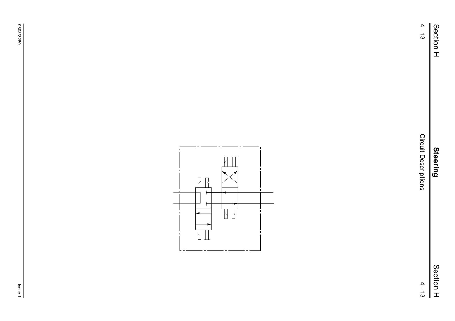
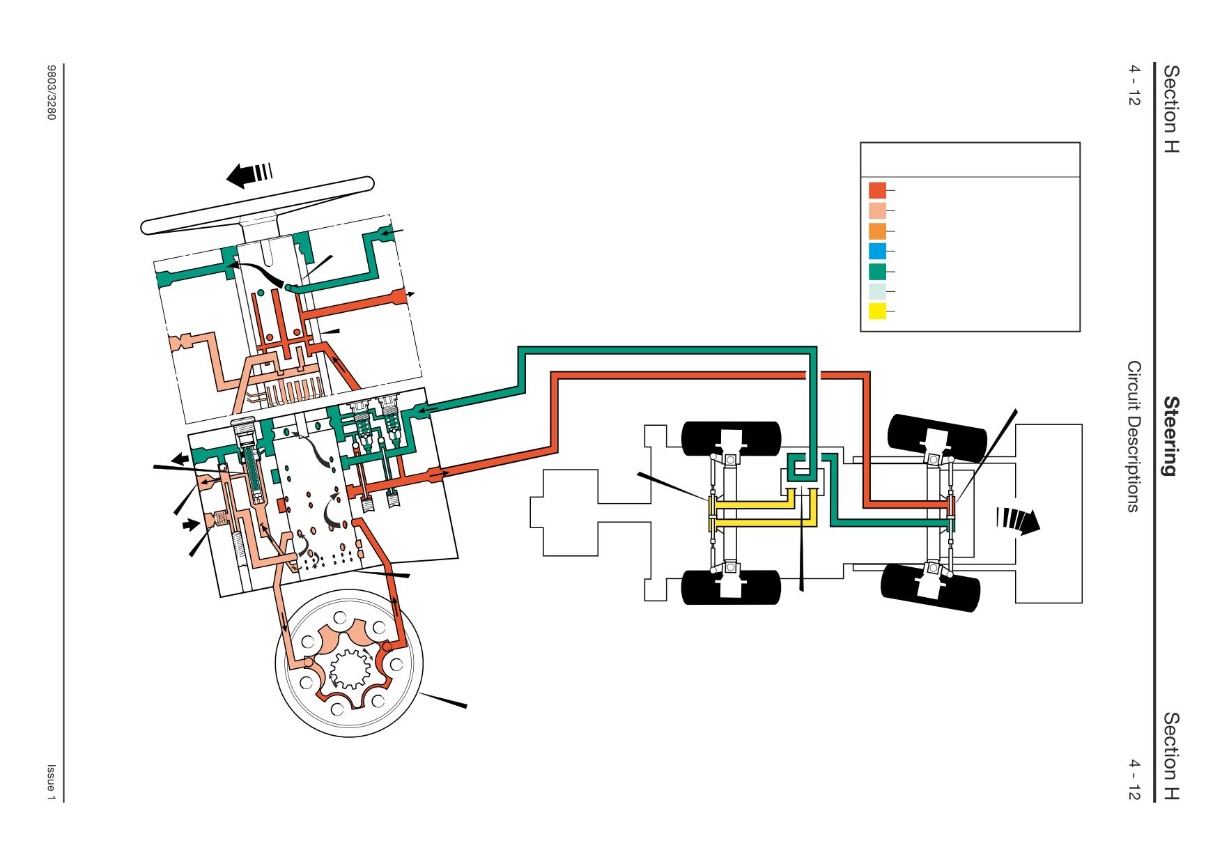
Steer Unit Operation
- 4 Wheel Steer Machines
2 Wheel Steer Mode
- Right Turn
The illustration shows the flow through the steering
unit in a right hand turn condition. The operation is
identical to that described for the 4 wheel steer
mode, except the steer mode control valve X
iscolates the oil flow to the rear power track rod
ram 41, consiquently the rotor lobes pump oil out
to the front power track rod only. The rear wheels
are held in the straight ahead position by the
locked-up oil in the rear power track rod ram.
In 2 wheel steer mode the spools of the steer mode
control valve X are configured as shown.
Component Key:
A Inner Spool
B Outer Spool
D Stator
LS Load Sensing Port
X Steer Mode Control Valve
40
Front Power Track Rod Ram
41
Rear Power Track Rod Ram
43B Relief Valve
43C Non-Return Valve
A395740
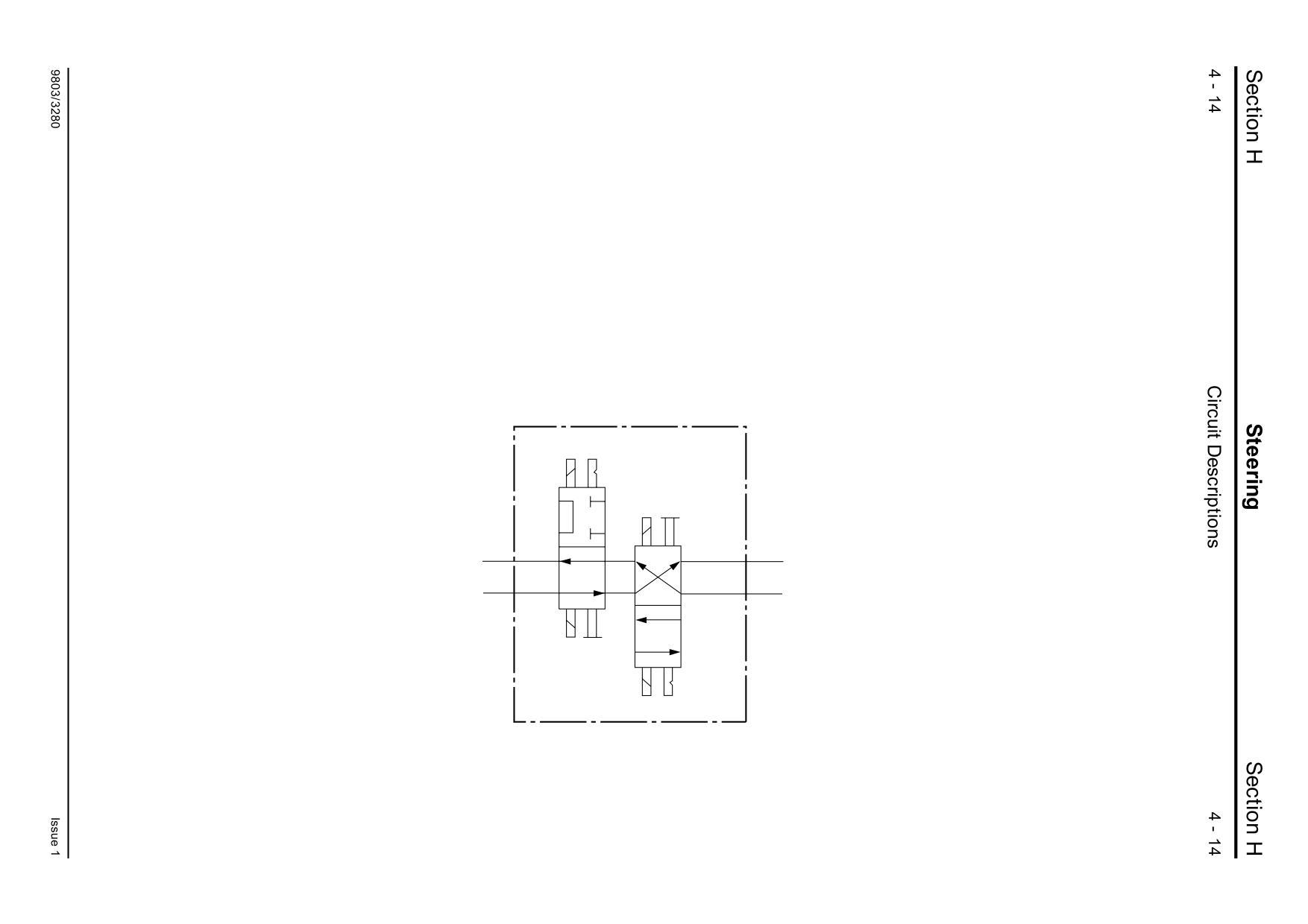
Steer Unit Operation
- 4 Wheel Steer Machines
Crab Steer Mode
- Right Turn
The illustration shows the flow through the steering
unit in a right hand turn condition. The operation is
identical to that described for the 4 wheel steer
mode, except the steer mode control valve X
directs the pressurised oil from the front power
track rod ram 40 to the other side of the rear power
track rod ram 41, hence turning the rear wheels in
the same direction as the front wheels, causing the
machine to crab to the right.
In crab steer mode the spools of the steer mode
control valve X are configured as shown.
Component Key:
A Inner Spool
B Outer Spool
D Stator
LS Load Sensing Port
X Steer Mode Control Valve
40
Front Power Track Rod Ram
41
Rear Power Track Rod Ram
43B Relief Valve
43C Non-Return Valve
A395750
Key to Oil Flow & Pressure
Full Pressure
Pressure
Servo
A
Neutral
Exhaust
Cavitation
Lock Up
B
A390630
40
41
43B
LS
43C
B
X
D
A395690
Key to Oil Flow & Pressure
Full Pressure
Pressure
Servo
Neutral
Exhaust
Cavitation
2
Lock Up
EF
A390630
LS
2B
R-CF
2A
2C
3
43B
T
43B
T
LS
LS
P
43
A395710
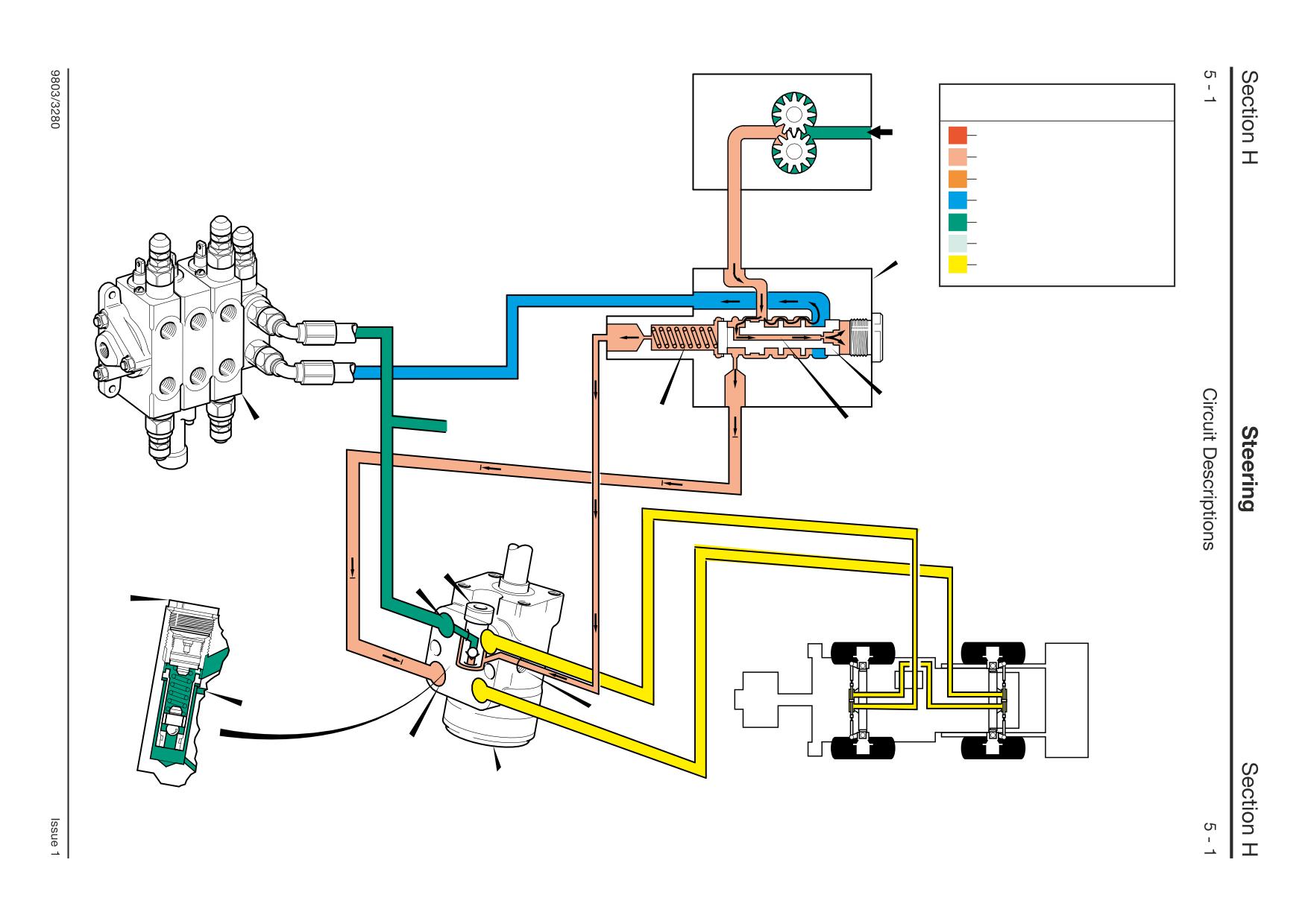
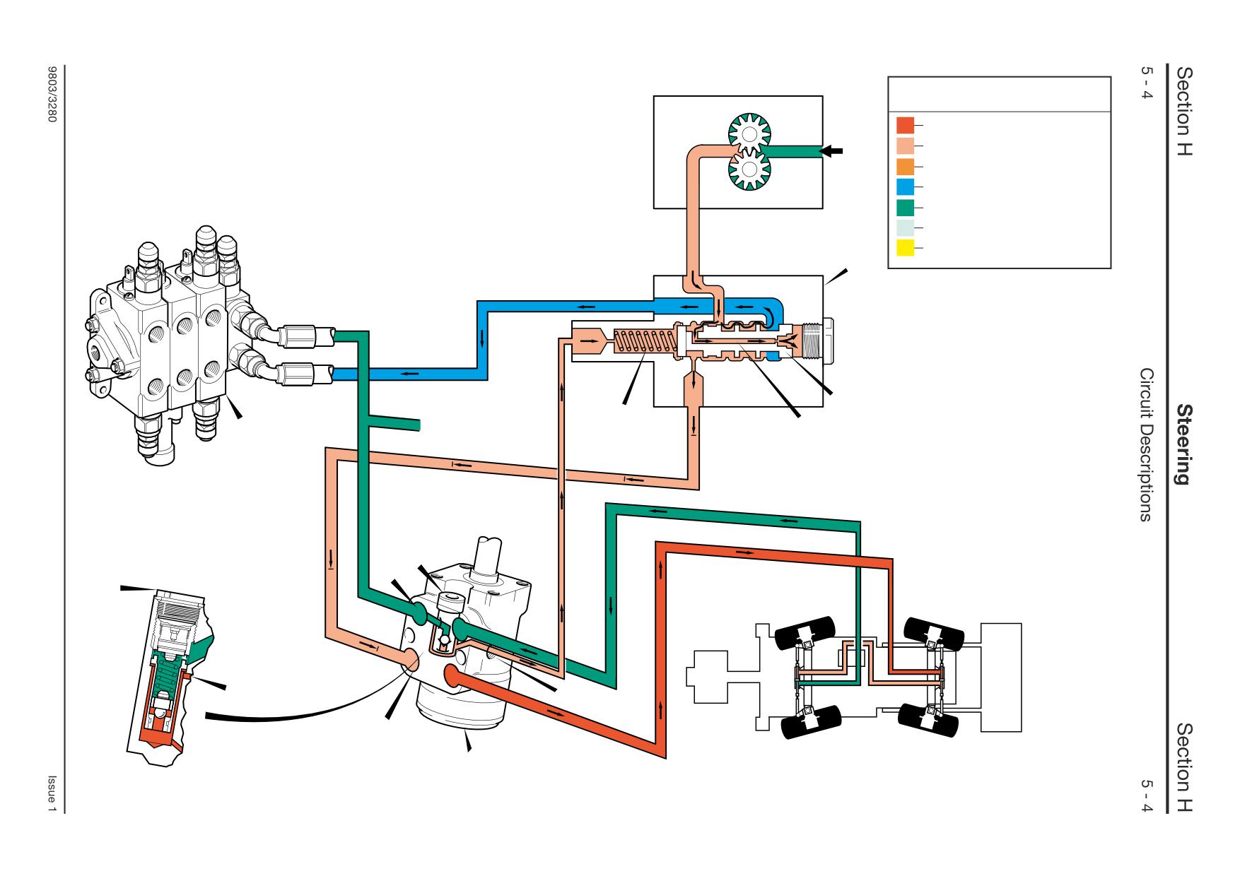
Priority Valve Operation 1
- Neutral
When the steering is not being operated, flow to the
steering circuit is dead ended by the closed centre
steering unit 43 and no load is sensed in line LS.
Pressure from the main pump to the priority valve is
fed via a drilling 2C to the rear of spool 2B. The
high pressure differential created across the spool
causes it to move to the left against the force of the
spring 2A. This allows full pump flow to the loader
control valve 3.
Component Key:
LS Load Sensing Port
P From pump
T To Loader Valve
2
Priority Valve
2A
Spring
2B
Spool
2C
Drilling
3
Loader Valve
43
Steer Unit
43B Relief Valve
Priority Valve Operation 2
- Turning
As the steering unit 43 is operated, pressure is
applied to the spring end of the priority valve spool
2B via sensing line LS from the steering unit.
This reduces the pressure differential across the
spool, causing it to move to the right under spring
force. This allows priority valve flow to the steering
unit which directs the flow to the power track rod
rams 40 and 41 untill the required steering lock is
reached. When the steering lock is held the
pressure signal across the side port LS of the
steering unit ceases, restoring the pressure
differential across spool 2B. The spool moves back
to the left, allowing full pump flow to the loader
control valve 3.
Because the pump output is always greater than
the flow required to operate the steering system,
flow to the loader valve is never completely cut off.
Maximum steering system pressure is controlled by
relief valve 43B, located in the steering unit 43.
Component Key:
LS Load Sensing Port
P From pump
T To Loader Valve
2
Priority Valve
2A
Spring
2B
Spool
2C
Drilling
3
Loader Valve
40
Front Power Track Rod Ram
41
Rear Power Track Rod Ram
43
Steer Unit
43B Relief Valve
Key to Oil Flow & Pressure
Full Pressure
Pressure
Servo
Neutral
Exhaust
Cavitation
Lock Up
2
A390630
EF
LS
2B
R-CF
2A
2C
3
43B
T
43B
T
LS
LS
P
43
A395720
Section H
Steering
Section H
10 - 1
Fault Finding
10 - 1
Fault Finding Contents
Introduction
Page No.
The purpose of this section is to help you trace hydraulic
faults to a faulty unit (valve, actuator, ram etc). Once you
have traced the faulty unit, refer to the appropriate
Introduction
10 - 1
dismantling, inspecting and test instructions given elsewhere
in the steering section.
Steering wheel difficult to turn
10 - 1
To help identify circuits, valves, rams etc mentioned in the
Steering wheel turns on its own
10 - 2
fault finding procedures, refer to the hydraulic schematic
Machine will not turn when the
diagrams (near the beginning of the Hydraulics Section).
steering wheel turned.
10 - 2
1
Before you begin fault finding, read the Safety
information at the beginning of this manual.
Steering fails to respond to
selected mode (4WS Machines only)
10 - 3
2
Make simple checks before say, stripping a major
component.
3
Make sure that the hydraulic fluid is at correct working
temperature (50 °C, 122 °F).
4
What ever the fault, check the condition of the hydraulic
fluid. Drain and replace if necessary.
5
Make any relevant electrical checks before moving on
to the hydraulics.
6
Be sure to remove ALL contamination and if possible
identify its origin. It may be part of a component from
elsewhere in the circuit.
7
Replace any seals such as 'O' rings before re-
assembling hydraulic components.
Fault
Probable Cause
Action
1
Steering wheel difficult to turn.
Tyres not inflated to
Inflate tyres to correct
correct pressure
pressure
Insufficient hydraulic fluid.
Check for leaks and top
up the hydraulic tank as
required.
Leaks in the relevant hoses or
Check hoses and
component connections
connections for leaks
Air in the hydraulic system.
Bleed system - bleed the
load sense line.
Low pump flow.
Check pump flow, if
required service or
replace pump.
Steer relief valve set
Check pressure setting
incorrectly
of steer unit relief valve,
adjust as required.
Worn or damaged parts in the steer
Remove and inspect.
control valve.
....... continued
9803/3280
Issue 1
Section H
Steering
Section H
10 - 2
Fault Finding
10 - 2
Fault
Probable Cause
Action
1
Steering wheel difficult to turn.
Priority valve not operating
Check if the priority valve
(continued)
correctly
is sticking, rectify as
required.
Check the load sense line
from the steer unit to the
priority valve for signs of
leaking
or
poor
connection.
Steer mode valve not operating
Check if spools sticking,
correctly (4WS Machines only)
rectify as required
Check if solenoids
operating,
replace
solenoids as required
Mechanical failure
Check for damaged axle
components, such as
rams, trackrods, linkages
etc.
2
Steering wheel turns on its own.
Dirt in the steer control unit
Clean and inspect unit.
(causing sleeves to stick open)
Steer control valve centring springs
Check steer unit.
damaged, broken or missing.
Steer control valve - position of
Refer to Hydraulic Steer
rotor to shaft slot incorrect.
Unit - Dismantling and
Assembly.
Correct as required.
3
Machine will not turn when the
Insufficient hydraulic fluid.
Check for leaks and top
steering wheel turned.
up the hydraulic tank as
required.
Leaks in the relevant hoses or
Check hoses and
component connections
connections for leaks
Air in the hydraulic system.
Bleed system - bleed the
load sense line.
Low pump flow.
Check pump flow, if
required service or
replace pump.
Steer relief valve set
Check pressure setting
incorrectly
of steer unit relief valve,
adjust as required.
Worn or damaged parts in the steer
Remove and inspect.
control valve.
9803/3280
Issue 1
Section H
Steering
Section H
10 - 3
Fault Finding
10 - 3
Fault
Probable Cause
Action
3
Machine will not turn when the
Priority valve not operating
Check if the priority valve
steering wheel turned (continued).
correctly
is sticking, rectify as
required.
Check the load sense line
from the steer unit to the
priority valve for signs of
leaking
or
poor
connection.
Steer mode valve not operating
Check if spools sticking,
correctly (4WS Machines only)
rectify as required
Check if solenoids
operating,
replace
solenoids as required
Mechanical failure
Check for damaged axle
components, such as
rams, trackrods, linkages
etc.
Steer column splined shaft not fully
Check shaft
engaged in steer valve.
engagement.
Power track rod failure
Check power track rod for
signs of damge, leaks etc.
4
Steering fails to respond to
Selector switch faulty
Check selector switch,
selected mode (4WS Machines only)
replace as required
Proximity switches not operating
Check setting of
correctly
Proximity switches, reset
or replace switches as
required.
Steer mode valve not operating
Check if spools sticking,
correctly
rectify as required
Check if solenoids
operating,
replace
solenoids as required.
Leaks in the relevant hoses or
Check hoses and
component connections
connections for leaks
Electrical failure
Check relevant electrical
connectors, if problem
still persists, do a wiring
continuity check on
relevant circuits.
9803/3280
Issue 1
Section H
Steering
Section H
20 - 1
Service Procedures
20 - 1
Steering System - Bleeding
Whenever any hydraulic steering component is
disconnected or removed the system must be bled as
follows.
With the engine running, the following procedure must be
carried out in the correct order that is laid down. You must
not alter the order of selections and operations.
1
Select 2 Wheel Steer
(a) Turn steering wheel to left, until front wheels are
fully locked to the left.
(b) Turn steering wheel to right, until front wheels are
fully locked to the right.
2
Select 4 Wheel Steer
(a) Turn steering wheel to left, until front wheels are
fully locked to the left.
3
Select 2 Wheel Steer
(a) Turn steering wheel to full right lock.
(b) Turn steering wheel to full left lock.
(c) Turn steering wheel to full right lock.
4
Select 4 Wheel Steer
(a) Turn steering wheel to left, until the front wheels
are fully locked to the left.
5
Select 2 Wheel Steer
(a) Turn steering wheel to full right lock.
(b) Turn steering wheel to full left lock.
(c) Turn steering wheel to full right lock.
6
Select 4 Wheel Steer
(a) Turn steering wheel to left, until front wheels are
fully locked to the left.
7
Select 2 Wheel Steer
(a) Turn steering wheel to full right lock.
(b) Turn steering wheel to full left lock.
(c) Turn steering wheel to full right lock.
8
Select 4 Wheel Steer
(a) Turn steering wheel to left, until the front and rear
wheels are fully locked.
9803/3280
Issue 1
Section H
Steering
Section H
20 - 2
Service Procedures
20 - 2
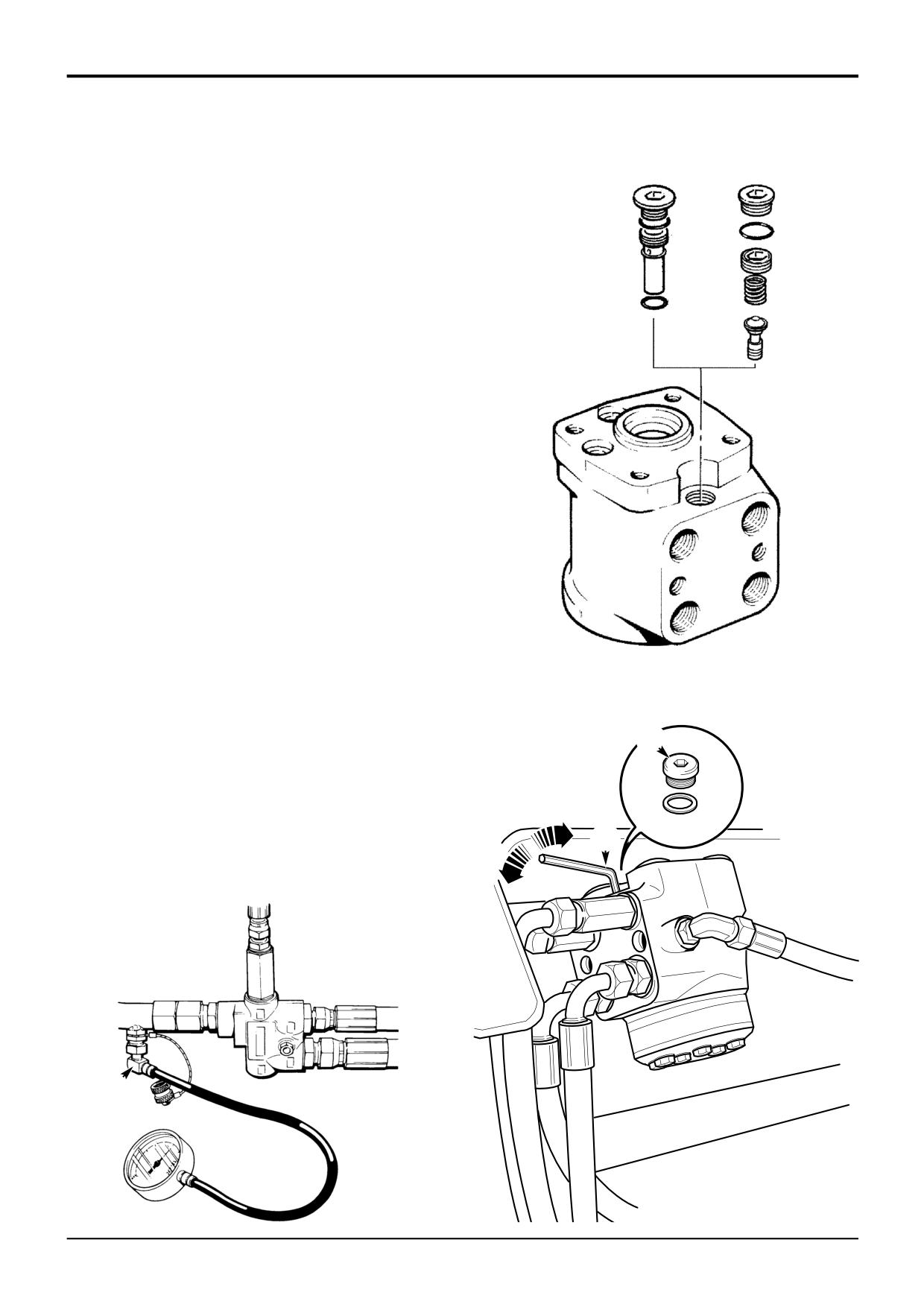
Steering System - Pressure Testing
X
Y
1
Park the machine on level ground, engage the parking
brake and set the transmission to neutral. Lower the
attachments to the ground. Stop the engine and
remove the starter key.
2
Turn the steering wheel to the left and to the right
several times to vent system pressure.
! WARNING
Make the machine safe before working underneath it.
Park the machine on level ground, lower the arms. Apply
the parking brake, put the transmission in neutral and
stop the engine. Chock both sides of all four wheels.
Disconnect the battery, to prevent the engine being
started while you are beneath the machine.
GEN-1-2
3
Connect a 0-400 bar (0-6000 lbf/in2) pressure gauge to
test adaptor A.
Note: The pressure test point for the steering circuit is fitted
next to the priority valve as shown.
4
Run the engine at 1500 revs/min and turn the steering
to full lock. Check the gauge reading which should
equal the relief valve pressure, refer to Technical Data.
S212750
Note: The steering wheel must be held on full lock whilst the
gauge reading is being checked.
5
If necessary, adjust the pressure setting by removing
plug B, on the hydraulic steer unit.
6
Adjust screw C using an 'allen key' until the correct
B
pressure is shown on the gauge.
Note: Detail X shows a relief valve which has a 4 mm
hexagon adjusting screw. Detail Y shows a valve which has
a 6 mm hexagon adjusting screw.
C
7
Refit plug B.
A
S263940
A390590
9803/3280
Issue 1
Section H
Steering
Section H
20 - 3
Service Procedures
20 - 3
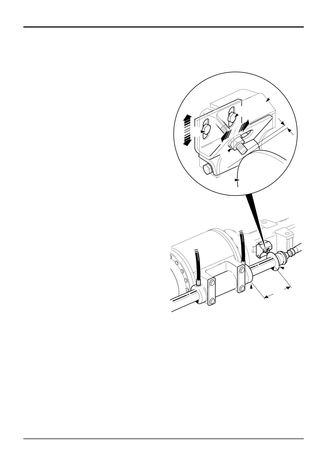
Proximity Switch - Setting
! WARNING
Raised loader arms can drop suddenly and cause
serious injury. Before working under raised loader arms,
fit the loader arm safety strut.
GEN 3-2
C
Note: The proximity switch setting procedure is the same for
both the front and rear axles. The illustration shows a typical
E
rear axle.
Y
1
Align the wheels in the straight ahead position. Check if
straight ahead by measuring the steering ram position.
E
Set the steering so that dimension X is equal both
sides.
D
2
Remove the proximity switch cover C.
3
With the starter switch on, loosen the proximity switch
lock nut D and slide the switch in line with the target
A
disc A.
4
Loosen the bracket fixing bolts E and adjust the
assembly up or down to bring the switch to the centre
of the target disc. Tighten the fixing bolts E.
Make sure the light emitting diode (L.E.D.) is not
illuminated (if it is then screw the switch out).
Now screw the proximity switch towards the target disc
until the light emitting diode (L.E.D.) on the switch
illuminates. Add a further 1 to 1.5 turns of the locknut.
Tighten the locknut.
A
X
B
X
A258170
9803/3280
Issue 1
Section H
Steering
Section H
20 - 4
Service Procedures
20 - 4
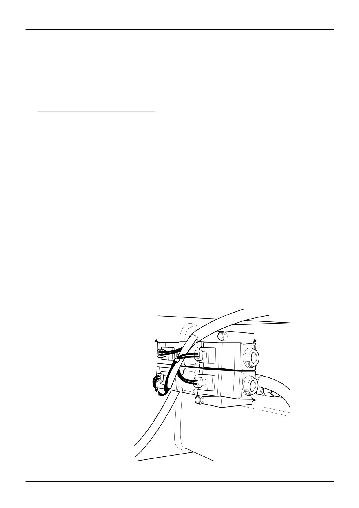
Steer Mode Valve
- Checking Solenoid Operation
The solenoids operate according to the steer mode that is
selected.
Mode:
Solenoid(s) Energised:
2 Wheel Steer
W
4 Wheel Steer
X, Z
Crab Steer
X, Y
Operation (energisation) of a solenoid can be easily detected
by placing a steel object (e.g. screwdriver blade) close to the
outer casing. A magnetic attraction of the steel object
towards the solenoid indicates energisation.
If a solenoid is not energising carryout the following checks:
1
Check the fuse is intact. If not, renew and then check
that all steer mode solenoid combinations function
correctly.
2
If the fuse is intact remove the electrical connector from
the malfunctioning solenoid(s) and check that the 12V
supply is present across the connector pins. If not,
check the supply circuit.
3
Check the solenoid coil resistance which should
measure a few ohms (if unsure of the value compare
with a known good solenoid).
Renew the solenoid if the reading indicates a short
circuit (zero ohms) or open circuit (infinate resistance). If
a reading somewhere between the two is obtained,
reverse the two instrument probes and repeat for a
valid check.
W
X
Y
Z
A396570
9803/3280
Issue 1
Section H
Steering
Section H
20 - 5
Service Procedures
20 - 5
Priority Valve - Cleaning
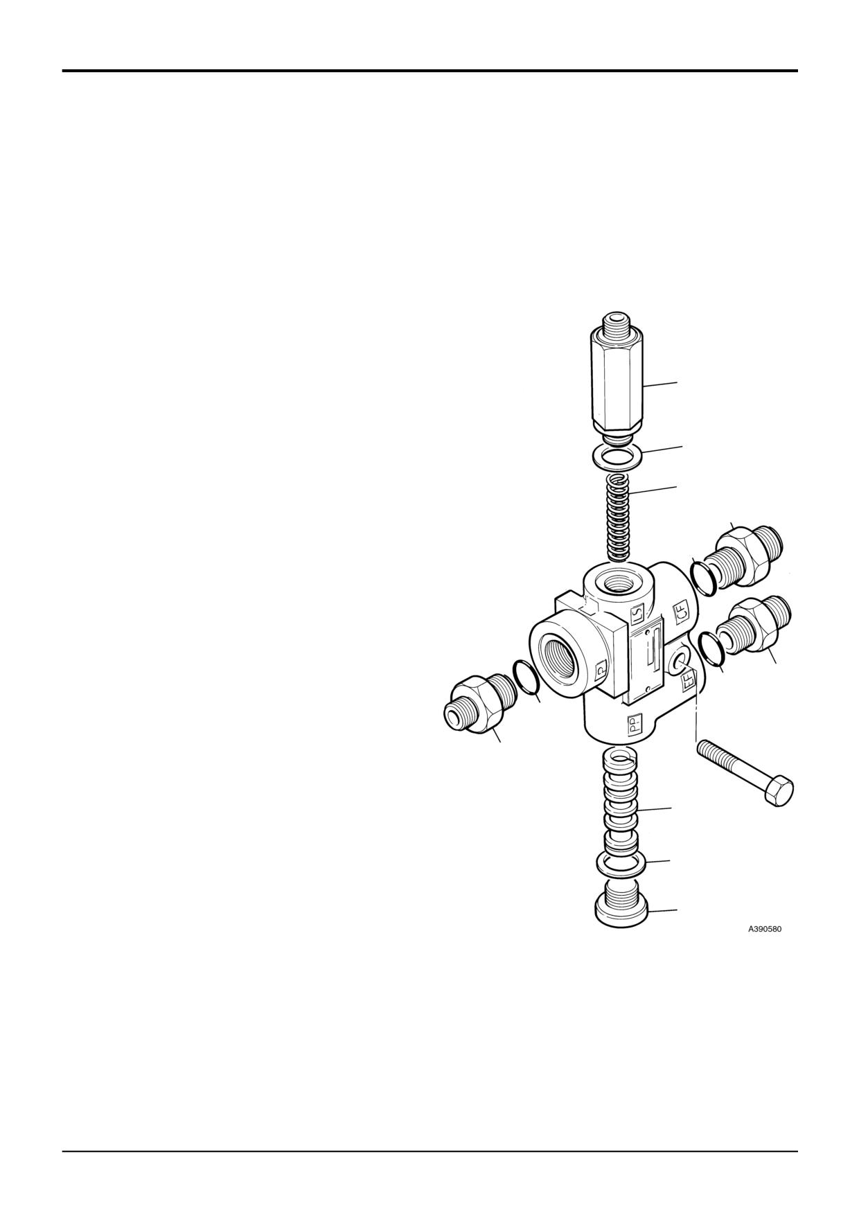
The priority valve spool and spring may be removed for
cleaning.
1
Remove the priority valve from the machine. Refer to
Priority Valve - Removal and Replacement.
2
Unscrew adaptor 9 and extract the priority valve spring
11.
3
Remove the blanking plug 7. Press out the priority valve
spool 12 using a nylon pin. Take care not to damage
the bore of the valve.
4
Clean these components in clean paraffin paying
particular attention to the orifices at each end of the
9
spool. Dry off and lubricate with clean hydraulic fluid.
5
Refit the priority valve spool 12 making sure that the
spring seat end of the spool faces towards the LS port.
10
Refit blanking plug 7 and torque tighten.
6
Refit the priority valve spring 11 and adaptor 9 and
11
torque tighten.
3
7
Refit the valve onto the machine. Refer to Priority
4
Valve - Removal and Replacement.
8
Bleed the load sensing line. Refer to Priority Valve -
Bleeding.
Torque Settings
1
Item
Nm
Ibf ft
2
7
50
37
9
50
37
6
5
12
A
8
7
9803/3280
Issue 1
Section H
Steering
Section H
20 - 6
Service Procedures
20 - 6
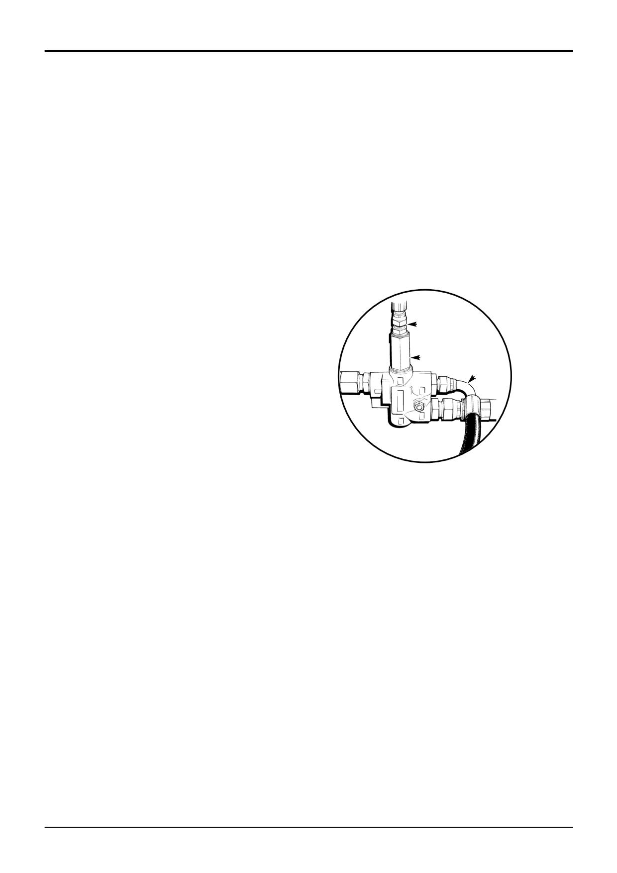
Priority Valve - Standby Pressure Testing
1
Disconnect hose A and install a 0 - 40 bar (0 - 580
lbf/in2) pressure test gauge into the valve port. Position
the open end of hose A into a clean container in order
to collect any oil drainage.
2
Disconnect hose B from load sensing port adaptor C
and blank off.
3
Set the steering to neutral, i.e. do not turn the steering
wheel, and start the engine. Gradually increase the
engine speed to 1000 rev/min while checking the
maximum pressure gauge reading which should be 5.9
to 8.7 bar (86 to 126 lbf/in2)
If the pressure is outside the limits try cleaning the priority
valve, refer to Priority Valve - Cleaning.
If cleaning the valve does not rectify, check the hydraulic
pump flow rate, refer to Section E Main Pump - Flow and
B
Pressure Testing.
If the hydraulic pump flow and pressure tests are
satisfactory, then the priority valve must be renewed.
C
A
9803/3280
Issue 1
Section H
Steering
Section H
30 - 1
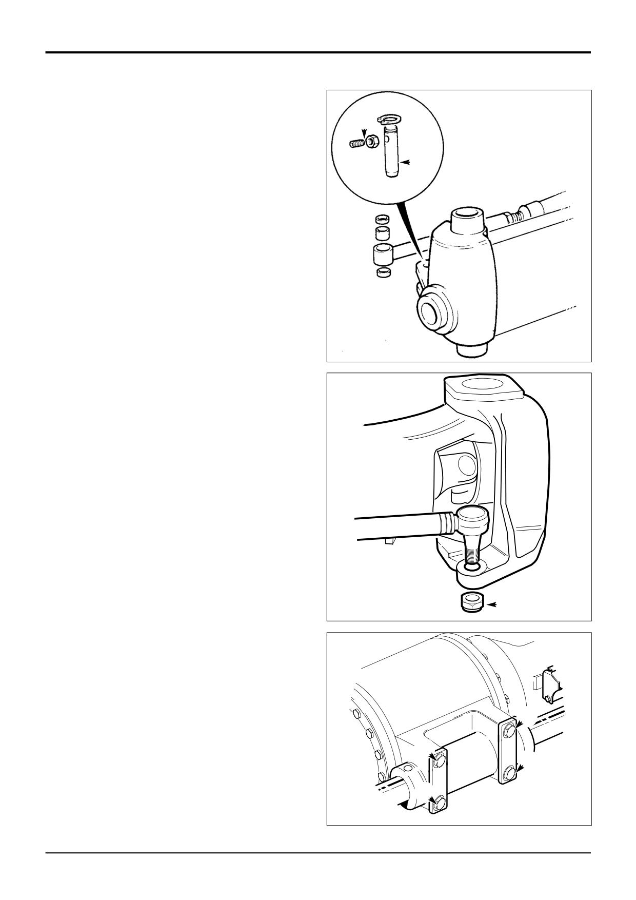
Power Track Rod
30 - 1
Removal and Replacement
This procedure is for a typical power steering track rod
B
removal and replacement.
! WARNING
C
Make the machine safe before working underneath it.
Park the machine on level ground, lower the arms. Apply
the parking brake, put the transmission in neutral and
stop the engine. Chock both sides of all four wheels.
Disconnect the battery, to prevent the engine being
started while you are beneath the machine.
GEN-1-2
! WARNING
Raised loader arms can drop suddenly and cause
serious injury. Before working under raised loader arms,
fit the loader arm safety strut.
GEN-3-2
A258510
Removal
1
Disconnect and cap hydraulic hoses to prevent loss of
fluid and ingress of dirt. Label hoses for identification
and correct refitting.
2
On 4WD machines remove the split pin and nut A.
Remove the track rod ball joint from the wheel hub
assembly.
On 2WD machines, remove lock assembly B and pin C
to remove the track rod pivot from the wheel hub
assemblies.
3
Remove the four fixing bolts D.
Replacement
1
Replace the power track rod by reversing the removal
procedure. On 4WD machines make sure that the split
pin is fitted.
A258490
2
After connecting hoses check hydraulic fluid level, if
necessary top up.
A
3
Bleed hydraulic steering system, refer to Service
Procedures, Steering System - Bleeding.
Torque Settings
Item
Nm
kgf m lbf ft
A
D
620
63
457
D
D
D
D
A258500
9803/3280
Issue 1
Section H
Steering
Section H
31 - 1
Power Track Rod
31 - 1
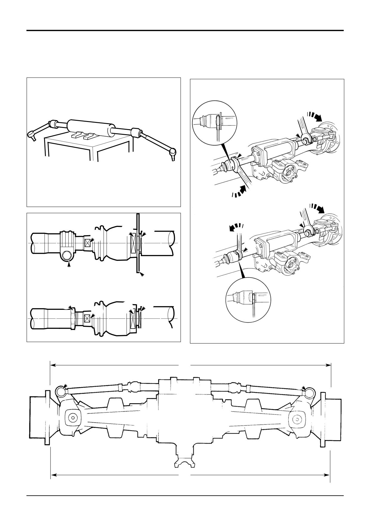
Link Arms - Removal and Replacement
M
L
A258480
A
M
F
E
J
N
H
G
B
K
E
F
J
A258470
S300370
X
C
C
Y
S258450
9803/3280
Issue 1
Section H
Steering
Section H
31 - 2
Power Track Rod
31 - 2
Link Arms - Removal and Replacement
Removal
Replacement
1
Fix the assembly on a locally made strip/rebuild bench
Replacement is the reverse of removal but note the
as shown.
following:
2
Using two suitable open ended spanners at L and M
1
Remember to fit the target disc G (where applicable).
react against each other until one ball joint unscrews.
2
Use JCB Threadlocker & Sealer on the trackrod link
arms.
3
Unscrew the ball joint L until an open ended spanner
can be fitted on the rod N. Screw the ball joint against
3
If the link arms have been renewed, the wheel
the spanner to secure the spanner and to prevent
alignment must be checked as follows:
damage to the rod.
a Set the wheels to the straight ahead position and
measure dimensions X and Y (at the outer edge of
4
By reacting against the spanner at N and M undo the
the wheel hub). Alignment is correct if the
other ball joint.
difference between X and Y is a maximum of 1
mm.
Note 1: Flats at ‘E’ are:
2 Wheel drive machines - 32 mm A/F x 4 mm wide.
b To adjust the wheel alignment undo the lock nuts
4 Wheel drive machines - 40 mm A/F x 4 mm wide.
(H or K as applicable). Turn the threaded adjusters
J equally to obtain the correct alignment. Tighten
Note 2: The piston rod operates at full length, any damage
the lock nuts (H or K as applicable).
to the surface will cause fluid leaks. DO NOT attempt to grip
the rod diameter with pipe grips etc.
Note 4: AWS machines shown at A. 2 wheel steer machines
shown at B.
5
Repeat the procedure for the remaining link arm
assembly.
4
Check the proximity switch setting (where applicable).
Refer to Service Procedures, Proximity Switch -
6
Where applicable remove the target disc G.
Setting.
Note 3: If the inner or outer ball joints need to be renewed,
then a replacement link arm assembly must be fitted.
Torque Settings
2WS /4WD C 180 Nm (132 lbf ft)
H 45/50 Nm (33/36 lbf ft)
E 240/260 Nm (177/184 lbf ft)
2WS/4WD
C 140/150 Nm (103/110 lbf ft)
K 300 Nm (221 lbf ft)
E 240/260 Nm (177/184 lbf ft)
AWS/4WD C 270/280 Nm (199/206 lbf ft)
H 70/85 Nm (51/62 lbf ft)
E 450 Nm (331 lbf ft)
AWS/4WD C 270/280 Nm (199/206 lbf ft)
K 390/410 Nm (287/302 lbf ft)
E 450 Nm (331 lbf ft)
2WS/2WD
C N/A
K 240/260 Nm (177/184 lbf ft)
E 240/260 Nm (177/184 lbf ft)
9803/3280
Issue 1
Section H
Steering
Section H
32 - 1
Power Track Rod
32 - 1
Rams
Dismantling and Assembly
A
1
A258580
7
6
5
8
3
4
D
3
8
S258430
5
1
2
B
6
C
7
A258590
9803/3280
Issue 1
Section H
Steering
Section H
32 - 2
Power Track Rod
32 - 2
Rams
Dismantling and Assembly
Assembly
1
Clean the threads of the end caps and cylinder using a
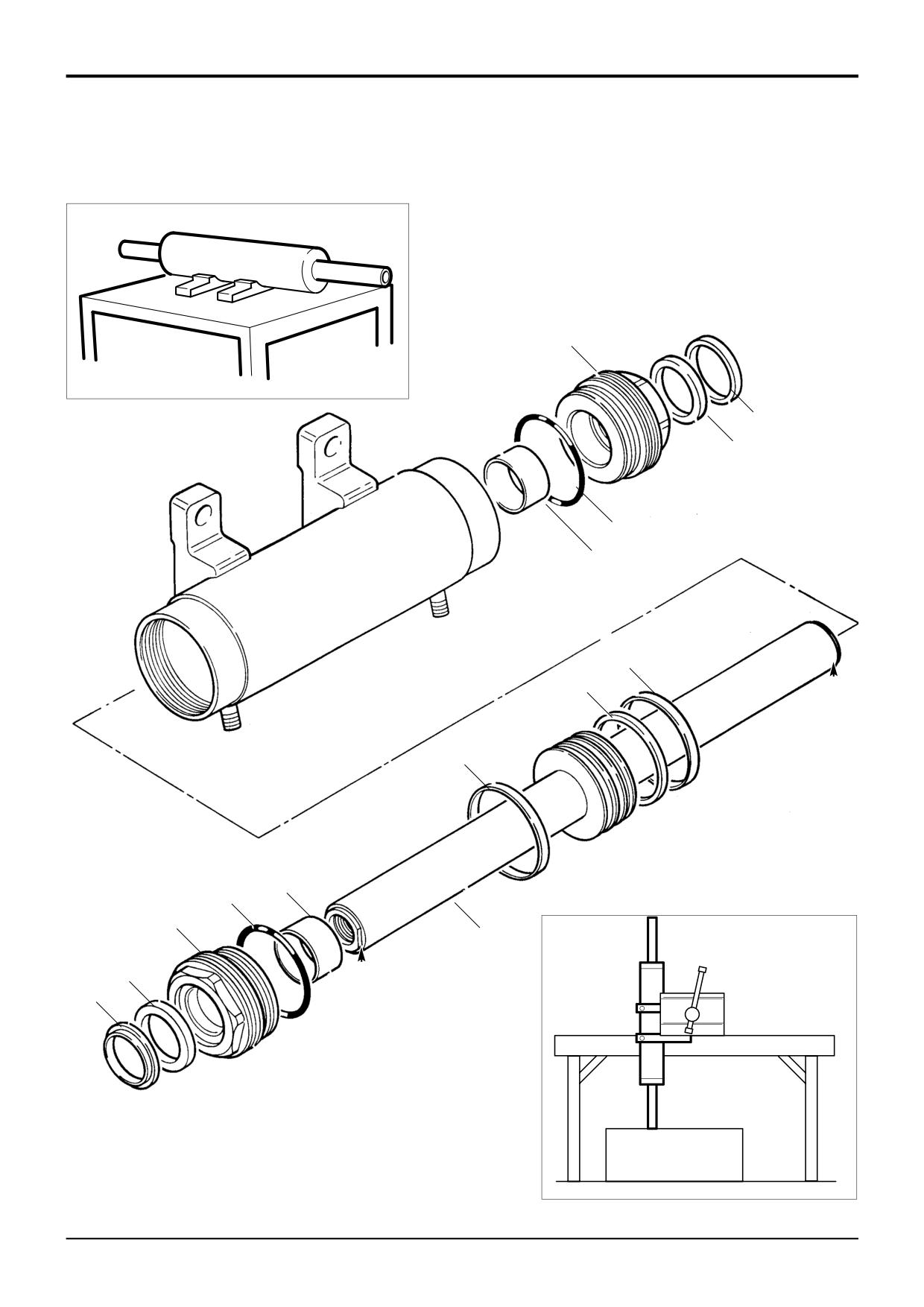
The numerical sequence shown on the illustration is
wire brush.
intended as a guide to dismantling.
2
Use JCB Cleaner & Degreaser to ensure that all
For assembly the sequence should be reversed.
threads are free from grease, hydraulic oil and sealant.
Allow 15 minutes for solvent to dry before applying
Dismantling
JCB Threadlocker and Sealer (High Strength).
1
Fix the ram assembly on a locally manufactured
Ensure that lubricants used during assembly do not
strip/rebuild bench as shown at A.
come into contact with the JCB Threadlocker and
Sealer (High Strength).
2
Remove both end caps, using a special spanner (refer
to Service Tools). Pull the piston rod assembly from
3
Refer to Section E Rams - JCB Ram Sealing
the cylinder.
Procedure for the correct method of fitting seals to the
end cap and piston head.
Note 1: DO NOT allow the piston rod to come into contact
with the cylinder bore. The cylinder bore may be damaged
4
Clamp the cylinder vertically and lower the piston rod
by careless dismantling.
assembly in from the top, as shown at B. Take care not
to allow the piston rod to come into contact with the
3
Position the piston rod assembly on a bench in place of
cylinder bore. Be sure to engage the piston head new
the ram cylinder. Remove the seal and wear rings from
wear rings and seal carefully into the cylinder. If the
the piston head.
piston head wear rings or seal are damaged during this
stage, they must be renewed.
Note 2: The piston head cannot be removed from the rod. If
there is damage to the rod or piston head, replace the
5
Apply JCB Activator to threads of the end caps and
cylinder. Allow Activator to dry for 15 minutes before
complete assembly.
bringing into contact with the JCB Threadlocker and
4
Carefully inspect the bore of the cylinder and the piston
Sealer (High Strength).
rod outer diameter for scoring, nicks and burrs. If such
Note 4: Neither the JCB Threadlocker and Sealer (High
damage is visible the components must be renewed.
Strength) nor Activator must be allowed to contact seals,
bearing rings or ‘O’ rings.
Note 3: If burrs are evident on the ends of the piston rod at
positions C or D remove by careful filing.
6
Apply JCB Threadlocker and Sealer (High Strength) to
threads of the ends caps, fit new ‘O’ ring 5.
Both end cap assemblies are the same, dismantle as
follows:
7
Ensure that there are no burrs at the ends of the piston
rod, see Dismantling - Note 3:
5
Remove the ‘O’ ring 5, end cap seal 6 and wiper seal 7.
8
Fit an end cap over the piston rod. Apply light hand
6
The bearing bush 8 can be renewed if necessary.
pressure to the cap to engage the gland seal on the
However, time will be saved if a complete end cap and
piston rod. DO NOT use excessive force. Screw on the
bush assembly is obtained.
first end cap and then fix the assembly on the
strip/rebuild bench as shown at A. Fit the remaining
cap and then torque tighten both caps.
Note
5: If hydraulic oil contacts the uncured JCB
Threadlocker and Sealer (High Strength) a weakening of the
bond will result. Cure times vary according to the ambient
temperature. Allow a minimum of
2 hours between
assembly and filling the ram with oil.
Torque Settings
Item
Nm
kgf m lbf ft
1
678
69.2
500
Note
6: Cold weather operation. When operating in
conditions which are consistently below freezing, it is
recommended that the track rod is operated slowly to its full
extent in both directions before commencing normal
working.
9803/3280
Issue 1
Section H
Steering
Section H
40 - 1
Priority Valve
40 - 1
Removal and Replacement
Dismantling and Assembly
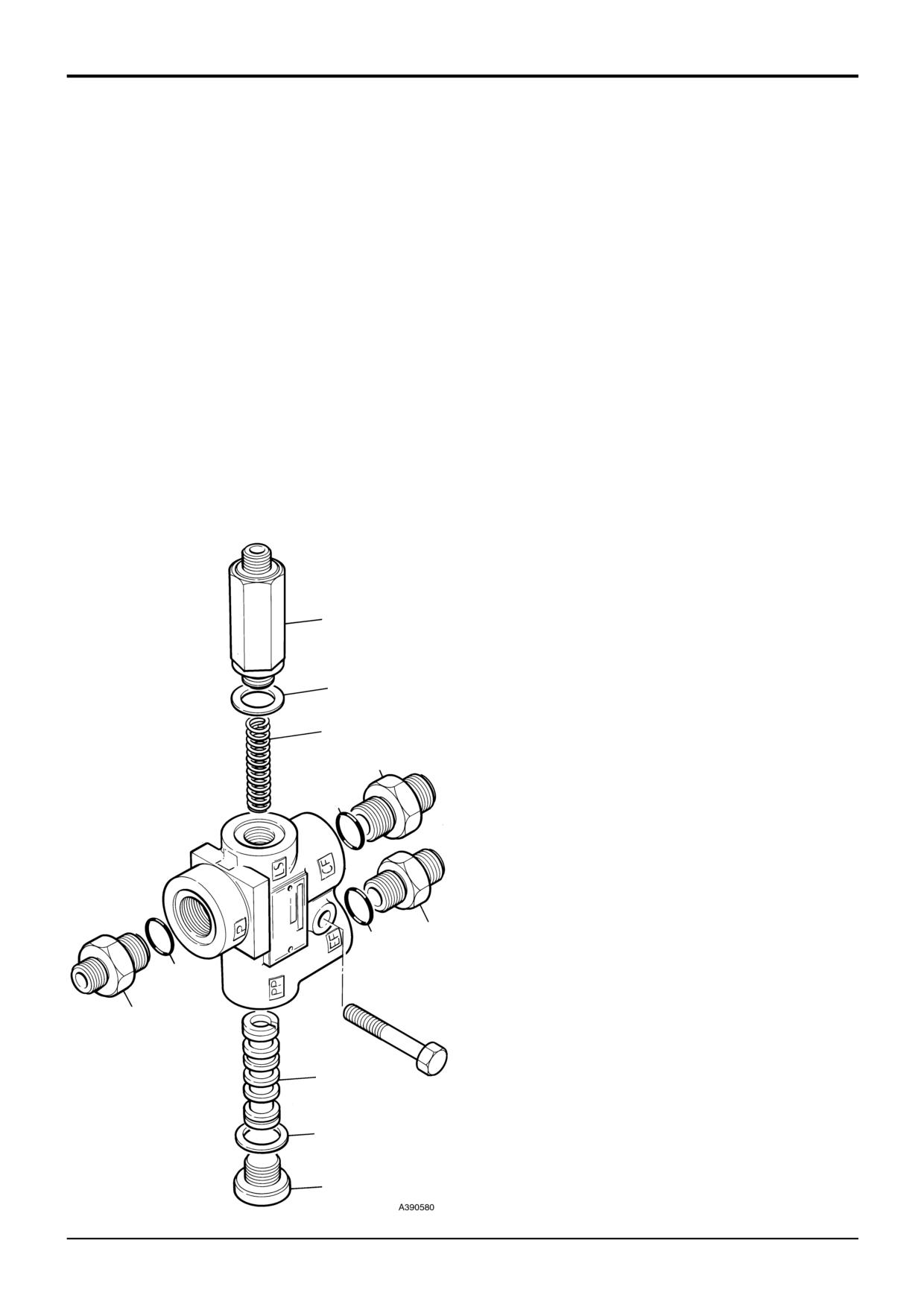
The numerical sequence shown on the illustration is
intended as a guide to dismantling.
! WARNING
Make the machine safe before getting beneath it. Lower
For assembly the sequence should be reversed.
the attachments to the ground; engage the parking
brake; remove the starter key, disconnect the battery.
Note 1: The priority valve is not serviceable beyond the
2-3-2-2
removal of foreign matter (Refer to Service Procedures,
Priority Valve - Cleaning). A faulty unit must be replaced.
The priority valve is mounted on the right hand side chassis
Dismantling
member, adjacent to the loader valve block. It is attached to
the chassis member by one bolt A, and is accessible from
Press out the spool item 12 using a nylon pin. Take care not
underneath the machine.
to damage the bores of the valve.
When replacing always renew sealing ‘O’ rings 2, 4, 6, and
Assembly
10.
Make sure that spring seat of spool 12 faces toward LS
connection.
Clean all parts in clean paraffin.
Lubricate all parts with hydraulic fluid.
Renew aluminium washers 8 and 10.
Note 2: All hydraulic adapters that are installed together with
a bonded sealing washer must also have JCB Threadseal
9
applied to the threads of the adapter.
Torque Settings
10
Item
Nm
lbf ft
7
50
37
11
9
50
37
3
Bleeding
4
To bleed the LS line, start the engine, loosen the connection
on the valve, turn and hold the steering wheel fully in either
direction. When bubble free oil flows from the joint, tighten
the connection.
1
2
6
5
12
A
8
7
9803/3280
Issue 1
Section H
Steering
Section H
45 - 1
Steer Mode Valve
45 - 1
Removal and Replacement
Replacement
! WARNING
Make the machine safe before working underneath it.
! WARNING
Park the machine on level ground, lower the arms. Apply
Fine jets of hydraulic fluid at high pressure can penetrate
the parking brake, put the transmission in neutral and
the skin. Do not use your fingers to check for hydraulic
stop the engine. Chock both sides of all four wheels.
fluid leaks. Do not put your face close to suspected
leaks. Hold a piece of cardboard close to suspected
Disconnect the battery, to prevent the engine being
leaks and then inspect the cardboard for signs of
started while you are beneath the machine.
GEN-1-2
hydraulic fluid. If hydraulic fluid penetrates your skin, get
medical help immediately.
INT-3-1-10/1
!
DANGER
Hydraulic Pressure
Replacement is a reversal of the removal sequence.
Hydraulic fluid at system pressure can injure you. Before
disconnecting or connecting hydraulic hoses, stop the
1
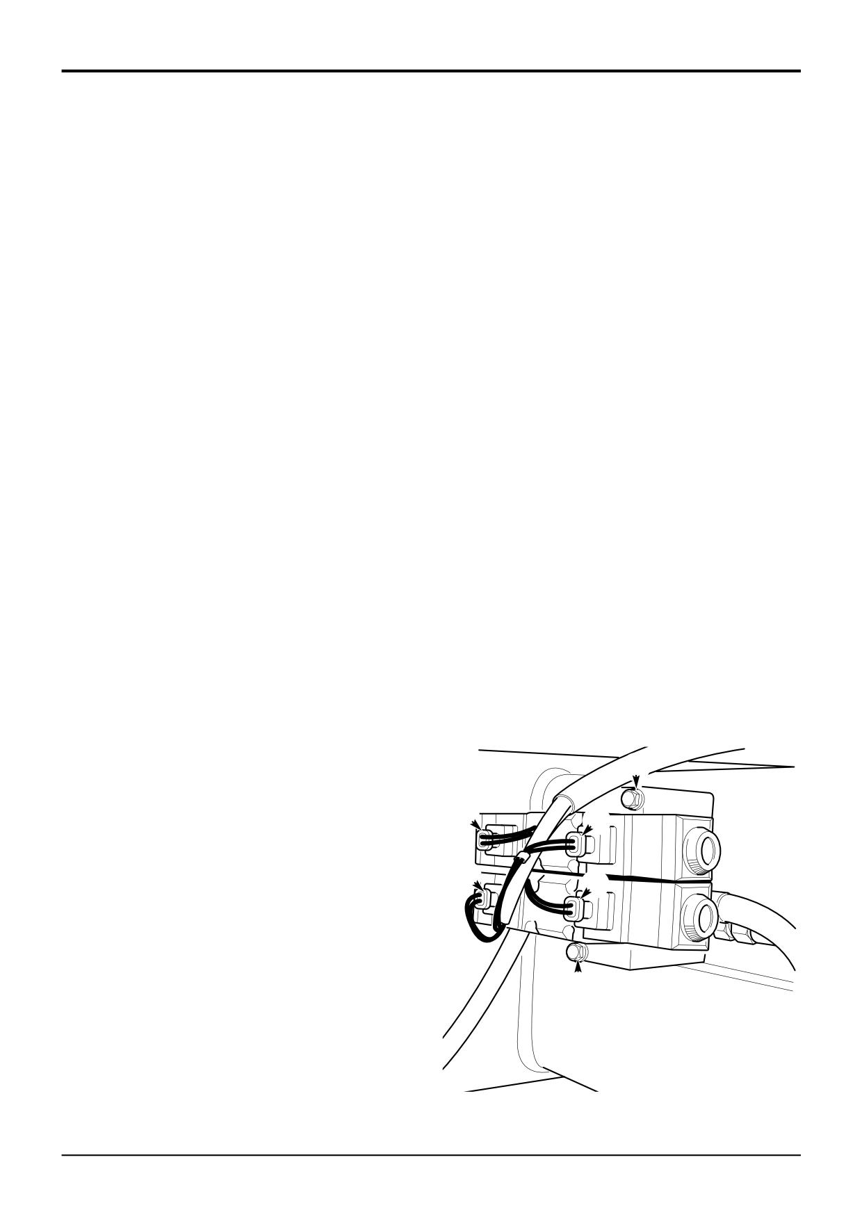
Make sure that the electrical solenoid connections are
engine and operate the controls to release pressure
refitted in the correct position.
trapped in the hoses. Make sure the engine cannot be
started while the hoses are open.
2
Make sure that the hoses are correctly installed. The
INT-3-1-11/1
hose connections from the steer mode valves assembly
are as follows:
Removal
P - to hydraulic steer unit (L port)
B - to rear power track rod (left side)
1
Park the machine on level ground, engage the parking
A - to rear power track rod (right side)
brake and set the transmission to neutral. Lower the
T - to front power track rod (right side)
attachments to the ground. Stop the engine and
remove the starter key.
Note 2: The steer mode valves assembly ports should be
stamped 'P', 'B', 'A' and 'T'. Left and right hand are as
2
Turn the steering wheel to the left and to the right
viewed from the rear of the machine.
several times to vent system pressure.
3
Bleed the steering system, refer to Service
Note 1: The steer mode valves assembly is fitted to a
Procedures, Steering System - Bleeding.
bracket which is mounted on the right hand side of the
machine in front of the rear axle.
3
Disconnect the electrical solenoid connections. Label
each connector before removal to ensure correct
refitting. The wires should be identified A, B, C and D
as shown.
E
4
Disconnect all hydraulic hoses from the steer mode
valves assembly. Label the hoses to ensure correct
refitting and cap the ends to prevent ingress of dirt.
A
B
5
Take hold of the steer mode valves assembly, loosen
and remove bolts E. Lift the steer mode valves
assembly and its retaining bracket from the machine.
C
D
E
A396570
9803/3280
Issue 1
Section H
Steering
Section H
45 - 2
Steer Mode Valve
45 - 2
Dismantling and Assembly
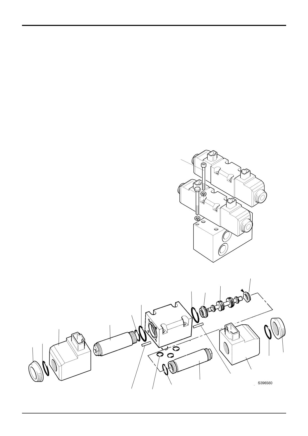
The numerical sequence shown on the illustration is
Assembly
intended as a guide to dismantling.
1
Renew all 'O' rings.
For assembly the sequence should be reversed.
2
Lubricate parts with JCB Special Hydraulic fluid before
Dismantling
assembling.
1
Before dismantling scratch an alignment mark X along
3
Use the alignment marks X (see dismantling) to ensure
the faces of the solenoid valves and the manifold block.
that the solenoids and the manifold block are
assembled correctly.
Note 1: Take care not to lose the detent balls A from items
16 and 18.
Torque Settings
Note 2: The illustration depicts a complete strip down, but
Item
Nm
lbf in
to carry out specific servicing/repairs, e.g. renewal of one of
1
7.1-9.1
63-80
the solenoids 3 and 6, it is only necessary to dismantle the
relevant components.
1
Note 3: None of the component parts of the CETOPS valve
assembly can be renewed individualy. The extent of
permissible servicing is cleaning and the consequential
renewal of 'O' ring seals. If damage to any component or
distortion of the spool is evident the complete valve
assembly must be renewed.
A396550
16
17
15
18
A
11
9
8
3
4
2
5
7
6
14
12
13
10
19
9803/3280
Issue 1
Section H
Steering
Section H
50 - 1
Hydraulic Steer Unit
50 - 1
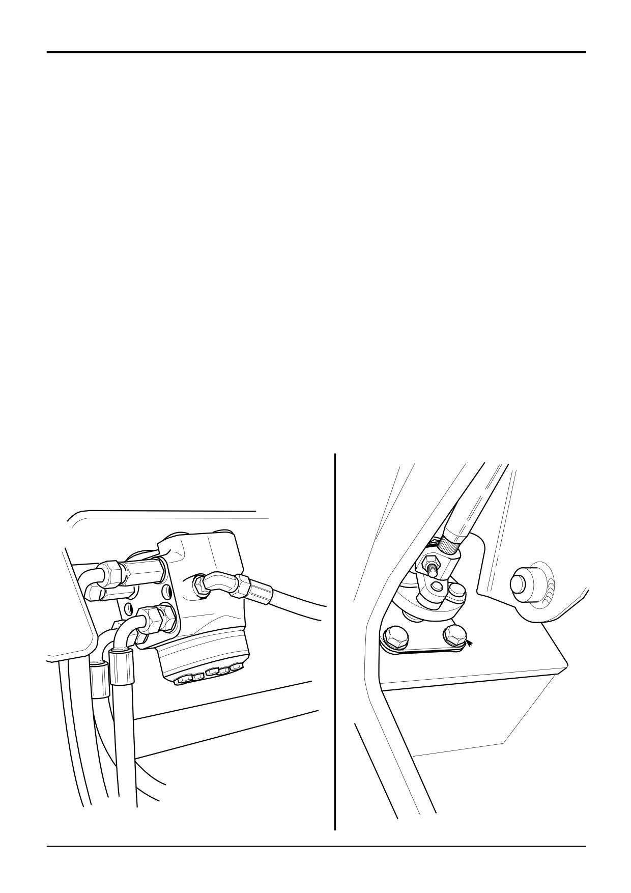
Removal and Replacement
Replacement
Removal
! WARNING
! DANGER
Fine jets of hydraulic fluid at high pressure can penetrate
Hydraulic Pressure
the skin. Do not use your fingers to check for hydraulic
Hydraulic fluid at system pressure can injure you. Before
fluid leaks. Do not put your face close to suspected
disconnecting or connecting hydraulic hoses, stop the
leaks. Hold a piece of cardboard close to suspected
engine and operate the controls to release pressure
leaks and then inspect the cardboard for signs of
trapped in the hoses. Make sure the engine cannot be
hydraulic fluid. If hydraulic fluid penetrates your skin, get
started while the hoses are open.
medical help immediately.
INT-3-1-11/1
INT-3-1-10/1
1
Park the machine on level ground, engage the parking
1
Replacement is a reversal of the removal sequence.
brake and set the transmission to neutral. Lower the
Make sure that the hoses are correctly installed.
attachments to the ground. Stop the engine and
remove the starter key.
2
Bleed the steering system. Refer to Service
Procedures, Steering System - Bleeding.
2
Turn the steering wheel to the left and to the right
several times to vent system pressure.
3
If a new steering unit has been fitted then the system
relief valve must be tested for correct pressure setting.
3
Disconnect and cap all hydraulic hoses from the
Refer to Service Procedures, Steering System -
steering unit as shown at A. Label the hoses to ensure
Pressure Testing.
correct refitting.
Note: All hydraulic adapters that are installed together with a
4
Get an assistant to hold the steering unit, and, working
bonded sealing washer must also have JCB Threadseal
inside the cab, loosen and remove 4 bolts B. Lift the
applied to the threads of the adapter.
steering unit from the machine.
A
B
A390610
9803/3280
Issue 1
Section H
Steering
Section H
50 - 2
Hydraulic Steer Unit
50 - 2
S10221A
9803/3280
Issue 1
Section H
Steering
Section H
50 - 3
Hydraulic Steer Unit
50 - 3
Dismantling and Assembly
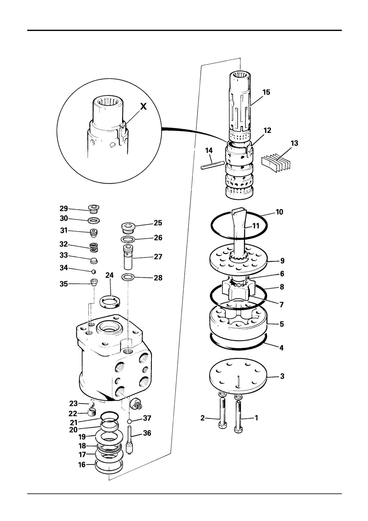
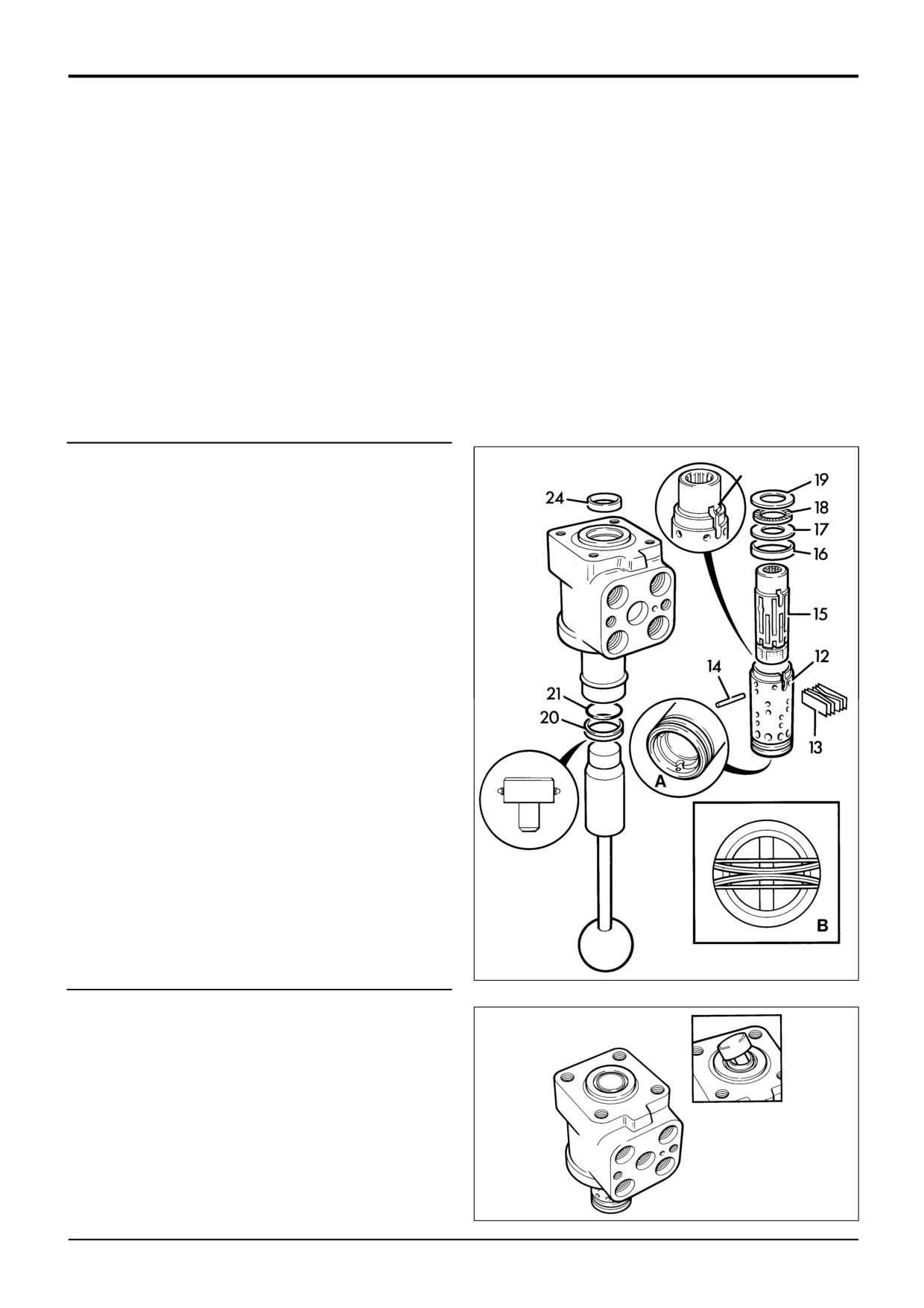
The numerical sequence shown on the illustration is intended as a guide to dismantling.
Note: 1 During manufacture, a small mark X will have been made on sleeve 12 and spool 15, close to one of the slots for the
centring springs 13. Before removing the centring springs, check that this mark is visible; if not, make a new mark to ensure
correct assembly.
Note: 2 Shock valves (items 29 to 35) are pressure set during manufacture and the adjusting screw 31 secured with Loctite.
Due to the difficulty of resetting the pressure it is recommended that the valves are not disturbed. If dismantling is
unavoidable, however, measure and record the depth of adjusting screw 31 below the top face of the steering unit before
removing the screw.
Note: 3 The unit illustrated in the following sequence represents a typical hydraulic steer valve. The relief valve (items 25 to
28) and shock valves (items 29 to 35) are not therefore shown in the following illustrations.
Assembly
X
1
Fit spool 15 into sleeve 12, aligning slots for centring
springs 13 and checking that the small marks X are
aligned. Ensure that three slots in spool partially
uncover three holes in sleeve, as at A.
2
Fit two flat centring springs 13 with four curved springs
between them, as shown at B.
3
Fit seal 24 into steer unit body and insert sleeve of
service tool 892/00180. Fit back up ring 20 and seal 21
onto plastic boss, and position on tool spindle, as
shown.
4
Lower steering unit body and tool sleeve over tool
spindle until plastic bush is flush with end of bore.
Assemble sleeves 12 and 15 with cross pin 14 and
centring springs 13. Fit bearing components 16 to 19
with chamfered face of 17 facing away from bearing 18.
S229680
5
Remove body from tool leaving plastic bush in position,
and lower body over assembled spool.
6
Apply downward pressure on body until plastic boss is
forced out of bore, leaving seals correctly located.
S229690
9803/3280
Issue 1
Section H
Steering
Section H
50 - 4
Hydraulic Steer Unit
50 - 4
Assembly (Continued)
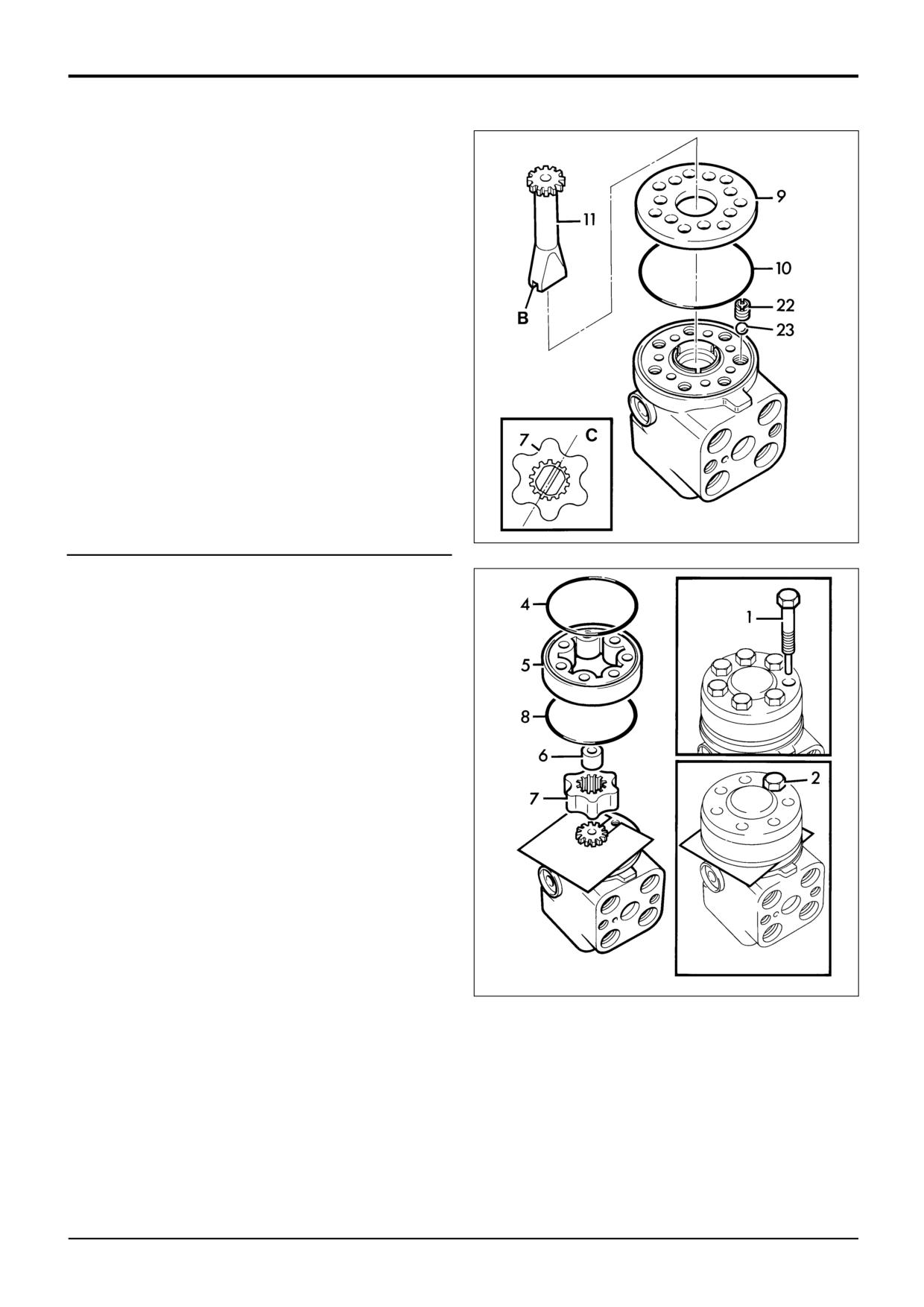
7
Invert unit and place on a suitable hollow support so
that body does not rest on protruding sleeve, thus
preventing displacement of the new seals. Place ball 23
into check valve hole and fit bush 22.
8
Fit new 'O' ring 10.
9
Fit distributor plate 9 ensuring that holes align. Locate
shaft 11 onto cross-pin 14, noting position of slot.
When rotor 7 is fitted, slot must align with hollows of
rotor as shown at C.
S229700
10
Use a suitable piece of rigid flat material, 0.25mm
(0.010 in.) thick, to support the shaft and ensure
positive engagement with the splines of rotor 7.
11
Locate rotor onto shaft, ensuring alignment as at C. Fit
spacing bush 6 into rotor.
12
Fit 'O' rings 4 and 8 each side of body 5, then position
body over rotor.
13
Refit the end plate and fit at least one bolt 2 before
removing support material.
14
Fit remaining bolts, ensuring that special bolt 1 is
correctly located. Tighten all bolts to 29Nm (22 lbf ft).
S229710
Pressure Relief Valve Cartridge
After renewing the 'O' ring, torque tighten the cartridge to 50 Nm (37 lbf ft). The relief valve is preset, refer to
Technical Data for the valve setting. The relief valve setting should be rechecked after fitting the steering unit to the
machine. Refer to Service Procedures, Steer System - Pressure Testing.
Shock Valves
If the shock valves have been dismantled, clean the threads of adjusting screw 31 and the threads in the bore of the steering
unit body using JCB Cleaner/Degreaser, allow to dry. Assemble seat 35, ball 34, cap 33 and spring 32 then coat threads of
screw 31 with JCB Threadlocker and Sealer. Assemble screw to depth measured during dismantling then fit plug 29 and
washer 30.
9803/3280
Issue 1
Section K
Engine
Section K
i
i
Contents
Page No.
Service Tools
1 - 1
Technical Data
2 - 1
Service Procedures
Fuel Lift Pump
- Cleaning the Strainer
20 - 1
Engine
- Removal & Replacement
30 - 1
9803/3280
Issue 1
Section K
Engine
Section K
1 - 1
Service Tools
1 - 1
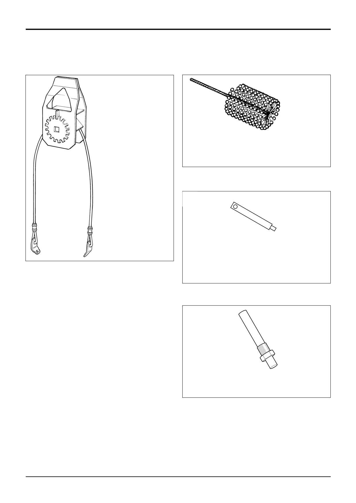
892/00836
Lifting Wire Assembly (for
engine removal)
S192390
892/00041
De-glazing Tool for Cylinder Bores (to
assist bedding-in of new piston rings)
A314530
S219080
892/00936
Timing pin for fuel injection pump
(AK, AM, AR)
892/0104
Adaptor for compression testing
(AK, AM, AR)
For details of other engine service tools refer to Engine
Service Manual, Publication No. 9806/0100 or 9806/2140 for
low emission engines.
9803/3280
Issue 1
Section K
Engine
Section K
2 - 1
Technical Data
2 - 1
Type
1000 Series 4 cylinder Engines
AB - Turbocharged
AA - Naturally Aspirated
AK - Turbocharged
AM - Turbocharged and Intercooled
AR - Naturally Aspirated
Engine Build List Number
AA50608 - AR50656, AR50654, AR50678 - 56kw (75bhp), AK50745 60kw (80bhp)
AA50606 - 56kw (75bhp)
AB50607 - 67.5 kw (90.5bhp), AK50628 - 68.5 kw (92bhp)
AB50609 - 71.5kw (96bhp), AK50640 - 74.6 kw (100bhp) AM50647 85.5 kw (115bhp)
Bore
AA, AB, AK, AM
100mm (3.937 in)
AR
103mm (4.055 in)
Stroke
127mm (5.000 in)
Swept Volume
AB, AA, AK, AM
4 litres (243 in3)
AR
4.23 litres (258 in3)
Compression Ratio
AB
16.0:1
AA
16.5:1
AK, AM
17.25:1
AR
18.5:1
Compression Pressure
28 bar (400 lbf/in2)
[maximum variation between cylinders 3.5 bar (50 lbf/in2)]
Injection Sequence
1,3,4,2
Valve Clearance - Cold
- Inlet
0.20mm (0.008 in)
- Exhaust
0.45mm (0.018 in)
Oil Pressure (hot) at maximum speed
- AA
2.1 bar (30 lbf/in2)
- AB, AK, AM
2.6 bar (40 lbf/in2)
- AR
2.0 bar (30 lbf/in2)
Maximum Air Cleaner Restriction
559mm (22 in H2O)
Injection System Details - Refer to appropriate Engine Service Manual.
Idling Speed
- All builds
880 - 930 rev/min
Maximum Governed Speed
- All builds
2200 rev/min
Maximum No-load Speed (High Idle)
- All builds
2400 - 2440 rev/min
Cooling System
Coolant Pressure
0.48 bar (7 lbf/in2)
Coolant Temperature (Normal)
80-85 °C (176-185 °F)
Temperature Warning Light operates at:
98 °C (208 °F)
Note: For further details of the engines refer to the following Engine Service Manuals:
Publication No. 9806/0100 (AA, AB)
Publication No. 9806/2140 (AK, AM, AR)
9803/3280
Issue 1
Section K
Engine
Section K
20 - 1
Service Procedures
20 - 1
Fuel Lift Pump
- Cleaning the Strainer
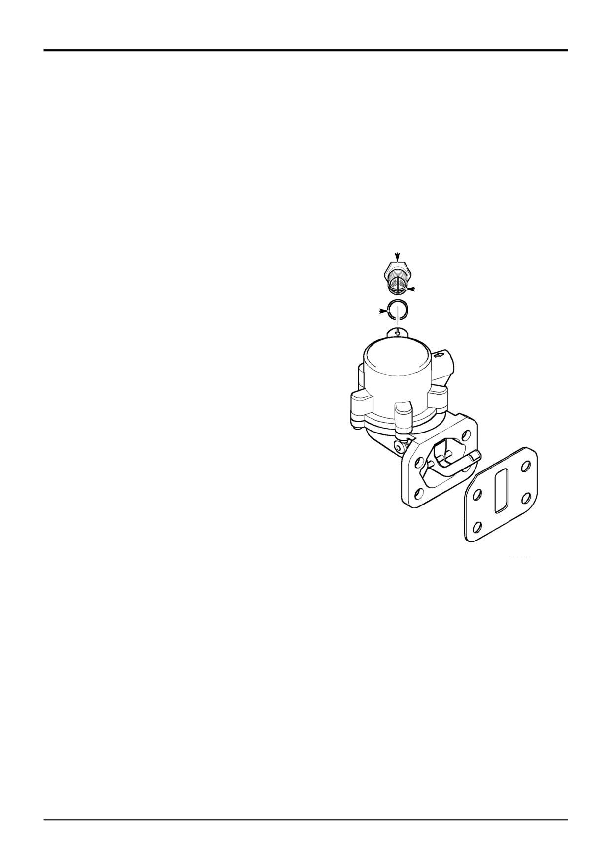
To remove and fit pump, see Engine Service Manual.
Remove and clean fuel inlet strainer 2 if blockage is
suspected ie. low engine power, difficult to start, fuel tank
contamination.
1
Allow the engine to cool. Remove the fuel filler cap to
vent the system and reduce loss of fuel. Disconnect the
fuel inlet pipe to the lift pump.
2
Unscrew the fuel filter A. Remove strainer 2 and O-ring
A
3.
3
Clean the strainer in clean diesel fluid and dry with low
pressure compressed air. Renew the strainer and O-
2
ring if damaged.
3
4
Fit the strainer into the fuel inlet connection. Fit the inlet
connector A and tighten to 20Nm (15 lbf ft). Fit the fuel
inlet pipe carefully to prevent damage to the strainer,
and tighten the union nut.
IMPORTANT: The fuel strainer can be damaged and fuel
flow can be restricted if the fuel pipe is inserted too far
into the inlet connection. This should be checked if a fuel
restriction is suspected.
Make sure the olive on the fuel inlet pipe is in good
condition and forms an effective seal. Renew the olive
or pipe if necessary to prevent air entering the fuel
system.
5
Fit the tank cap and prime the fuel system. Start the
engine and check for fuel leakage.
366610
9803/3280
Issue 1
Section K
Engine
Section K
30 - 1
Engine
30 - 1
c
Q
Q
c
R
S
A
S
b
a
a
b
P
N
A401530
9803/3280
Issue 1
Section K
Engine
Section K
30 - 2
Engine
30 - 2
Removal and Replacement
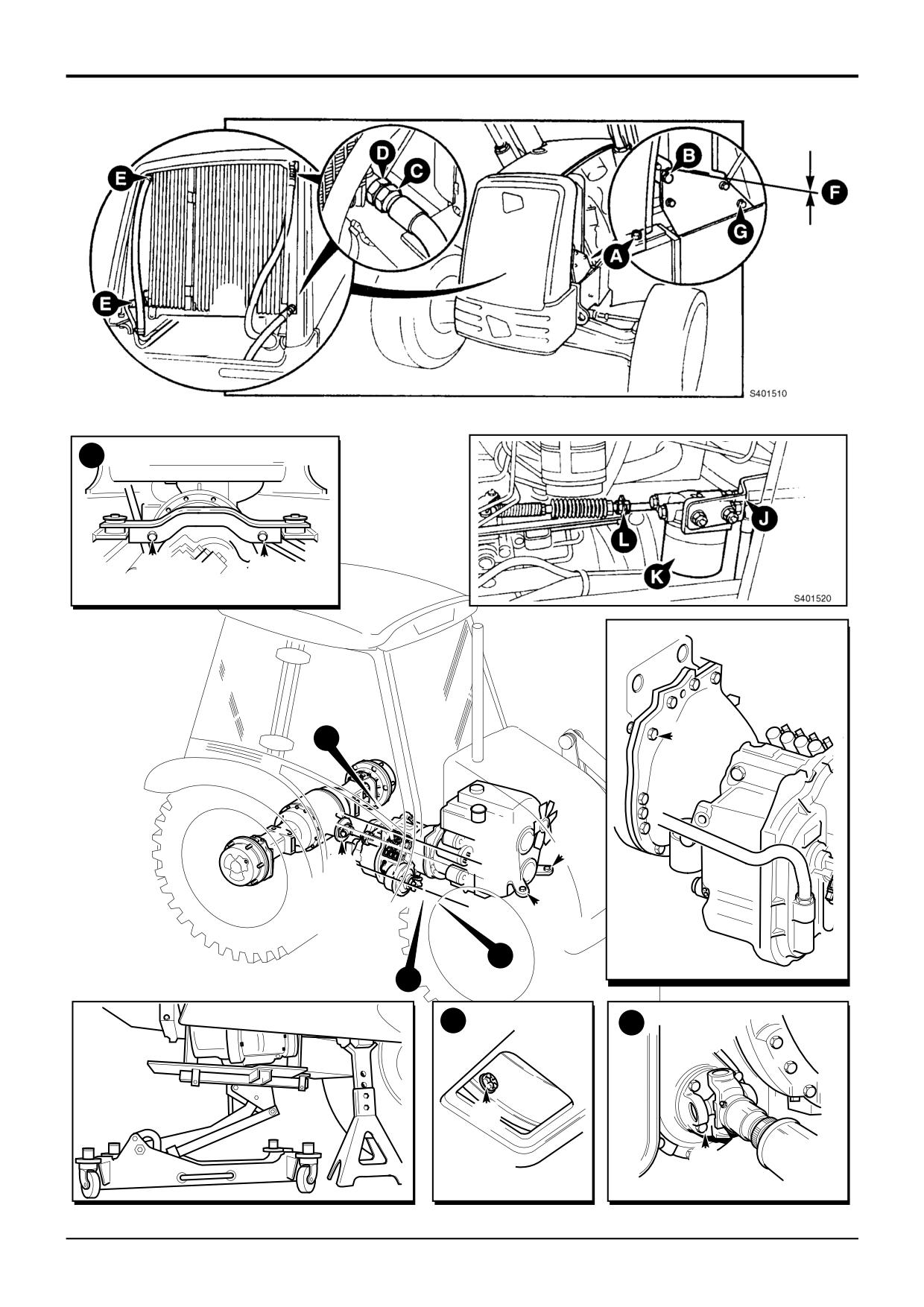
16
Loosen and remove the exhaust silencer retaining
Removal
bolts, remove the silencer.
1
Park the machine on firm level ground, engage the
17
Loosen and remove the retaining clamp for the heater
parking brake and set the transmission to neutral.
Chock the road wheels.
hose. Remove the hose.
2
Raise the loader arms and fit the loader arm safety
18
Loosen and remove the retaining clamp for the air filter
strut.
intake hose.
Note: In the event of engine failure, the loader arms will have
19
Remove the air intake filter. Use tape to close the
to be raised using suitable lifting equipment. Make sure that
opening in the air intake manifold, this will prevent
the loader control lever is in the ‘raise arms’ position before
ingress of dirt.
manually lifting the loader arms.
20
Loosen and remove the brake master cylinder reservoir
3
Remove the engine side panels
retaining bolts. Do not remove the pipes attached to
the master cylinder reservoir but put the reservoir out
4
Remove the engine cover (including the exhaust stack).
of the way. Make sure that the fluid level does not drain
down.
5
Disconnect the battery. When disconnecting the
battery, take off the earth (black) lead first.
21
Label and remove all electrical connections, the
number of connectors will vary depending on the
6
Remove retaining bolts and then lift off the front grille.
ancillary equipment fitted to the engine. Typical
electrical connectors are:
7
Remove retaining bolts A and B (both sides) and lift off
i)
starter motor
the front nose guard.
ii)
alternator
iii)
coolant pressure switch
8
Disconnect the hydraulic oil cooler hoses C from the
iv)
coolant temperature sender
hydraulic oil cooler. Plug and cap open ports to prevent
v)
engine oil pressure switch
ingress of dirt.
vi)
engine temperature sender
vii)
engine shut off solenoid
Note: When installing and removing hoses from the cooler, it
viii)
ether cold start (if fitted)
is essential to note that adaptor D must be held with a
ix)
air conditioning compressor (if fitted)
spanner whilst installing or removing the hose. It may be
easier to remove the top hose connection once the cooler
22
If air conditioning is fitted:
has been removed from the machine.
Note: The air conditioning is a pressurised closed loop
9
Drain the cooling system.
system, do not disconnect the hoses to the compressor.
Leave the hoses to the compressor intact.
10
Remove the transmission oil cooler hoses E.
a Remove the belt from the clutch of the air
11
Remove the radiator top hose and bottom hose.
conditioning compressor.
12
Remove the coolant bottle pipe.
b Disconnect the electrical connectors at the
compressor.
13
Make a suitable alignment mark to allow correct
repositioning of the radiator shroud, as shown at F.
c Loosen and remove the air conditioning
compressor retaining bolts.
14
If an engine fan guard is fitted, remove retaining bolts
and lift off the guard.
d Put the air conditioning compressor out of the way
(do not allow the compressor to ‘hang’ on its
15
Remove retaining bolts G (both sides) and lift off the
hoses).
radiator sub-assembly including radiator, hydraulic and
transmission coolers, and shroud. Take care not to
23
Loosen and disconnect the fuel lines J from the fuel
damage the engine fan, note also that the sub-
sedimenter. Plug and cap open orifices to prevent
assembly is heavy, use suitable lifting equipment.
ingress of dirt and loss of fuel.
Note: If required, the shroud, radiator and coolers can be
24
Loosen and remove the retaining bolts for the fuel
removed as individual items.
sedimenter, remove the sedimenter K.
......cont’d
9803/3280
Issue 1
Section K
Engine
Section K
30 - 3
Engine
30 - 3
Removal and Replacement
Replacement
Removal (continued)
Replacement is a reversal of the removal procedure.
25
If fitted, loosen and disconnect the ether cold start fuel
line from the engine. Plug and cap open orifices to
1
When mating the gearbox/torque converter to engine,
prevent ingress of dirt and loss of fluid.
ensure that the drive tangs are correctly located in the
gearbox pump. See Section F Gearbox Replacement
26
If fitted, loosen and remove the ether cold start canister
for a detailed procedure.
retaining bolts, lift off the canister and retaining bracket
assembly.
Note: It is vitally important that the torque converter is
fitted at the gearbox and engine flywheel correctly.
27
Disconnect the throttle linkage L from the arm on the
Failure to locate the converter correctly will result in damage
fuel injection pump. Leave at least one of the locking
to the gearbox oil pump on engine start up.
nuts in position, this will ensure that the engine revs are
set correctly when reassembling.
2
When you are satisfied that the torque converter is
located correctly, use the access hole in the bottom of
28
Loosen and remove the rear propshaft to gearbox
the gearbox to fit and tighten the flexi-plate to engine
retaining bolts M.
flywheel retaining bolts. Rotate the flywheel to align the
next bolt hole, fit and tighten all retaining bolts.
29
On 4WD machines, loosen and remove the front
propshaft to gearbox retaining bolts N.
3
When fitting the radiator sub-assembly, including
radiator, cooler and shroud take care not to damage
30
Remove the access bung located at the base of the
the engine fan, align the shroud using alignment mark
gearbox. Through the access hole, loosen and remove
made at step 13 in Removal.
the torque converter to engine flywheel retaining bolts
P (turn the flywheel to align bolts with access hole).
4
Make sure that the front nose guard and the engine
cover are correctly aligned.
31
If manual gearbox fitted, disconnect the gearshift lever
from the top of the gearbox.
5
Refill cooling system using correct mixture of
water/anti-freeze.
32
Use a suitable trolley jack and support the weight of the
gearbox.
6
Check engine, coolant and brake oil levels.
Note: Attach a ‘cradle’ to the trolley jack that will evenly
7
When connecting the battery, connect the earth (black)
support the weight of the gearbox. Refer to Service Tools.
lead last.
33
Use a suitable stand and support the weight of the
Make sure that the engine idle speed is correct, adjust as
engine.
required, refer to Technical Data.
34
Loosen and remove the gearbox mounting bolts Q.
Torque Figures
35
Remove the gearbox to engine retaining bolts R, pull
Item Nm
Kgf m
lbf ft
Description
the transmission and converter clear of the engine,
M
118
12
87
Rear propshaft bolts
make sure that the converter stays mounted on the
N
79
8
58
Front propshaft bolts
gearbox shaft.
P
44
4.5
32
Flexi-plate to flywheel bolts
Q
237
24
175
Gearbox mounting bolts
36
Attach suitable lifting chains to the engine (see Lifting
R
98
10
72
Gearbox to engine bolts
Wire Assembly, service tool 892/00836 in Service
S
85
8.7
63
Engine mounting bolts
Tools). Take the weight of the engine on the hoist.
Note: The engine oil pressure switch, water temperature
37
Loosen and remove the engine mounting bolts S (both
switch and water temperature sensor torque figure varies
sides).
depending on the material it is screwed into.
38
Lift the engine clear of the machine.
Nm
Kgf m
lbf ft
Plastic
4
0.4
3.0
39
Put the engine on a suitable stand, the correct
Aluminium
30
3.0
22
dismantling and assembly procedures are detailed in
the Engine Service Manual, publication number
9806/0100.
9803/3280
Issue 1