JCB 3CX, 4CX, 214e, 214, 215, 217 & VARIANTS Backhoe Loader. Service Manual - page 6
Section C
Electrics
Section C
2 - 2
Technical Data
2 - 2
Fuses and Relays
Fuses
10
10
10
9
9
9
8
8
8
7
7
7
! CAUTION
6
6
6
5
5
5
4
4
4
Always replace fuses with ones of correct ampere rating
3
3
3
2
2
2
to avoid electrical system damage.
1
1
1
8-3-3-5
C
B
A
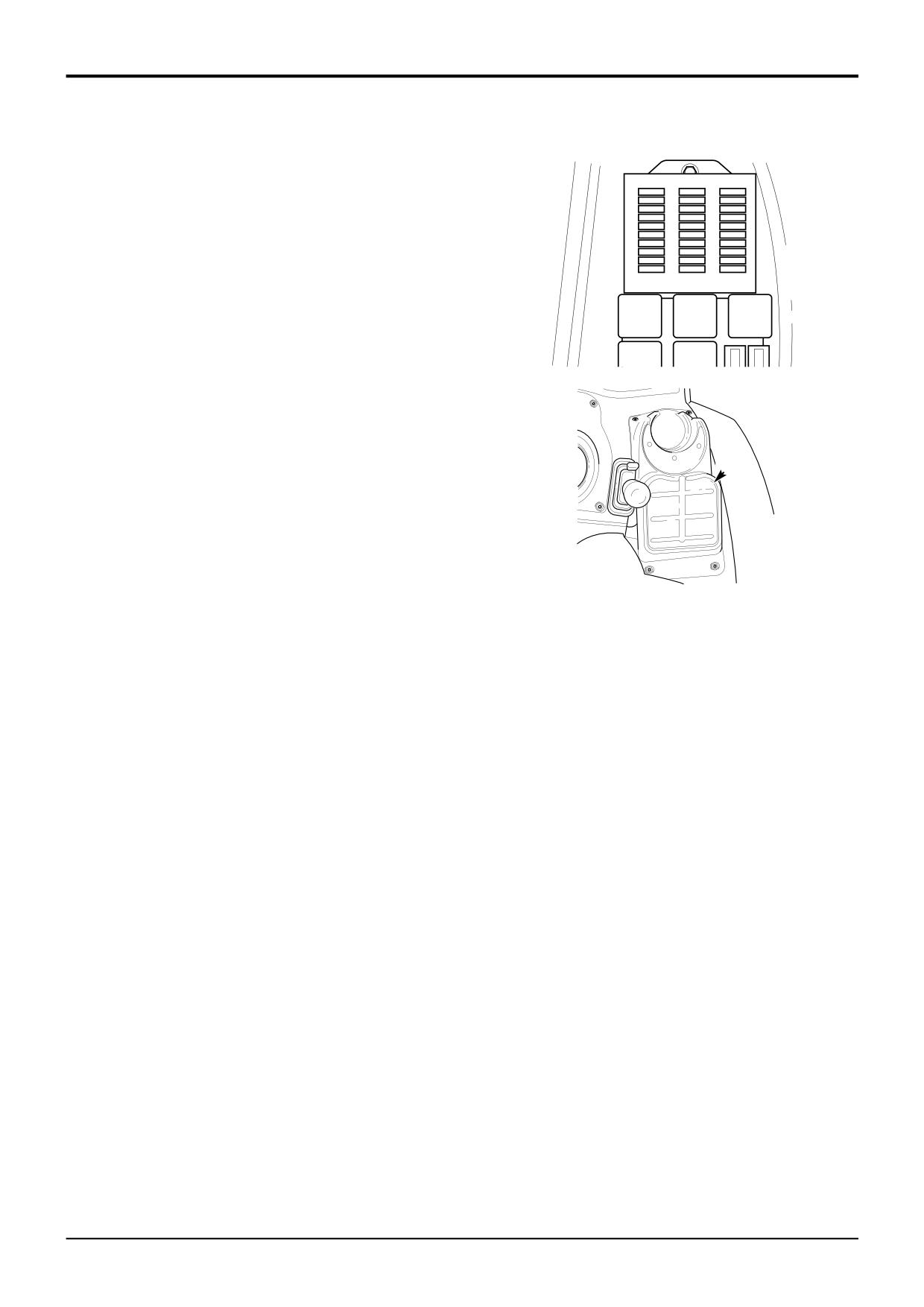
The relays and fuses are located in the side console
underneath cover A.
396500
If a fuse melts, find out why and rectify the fault before fitting
a new one. The fuses are identified using column letters (A,
B and C) and row numbers (1 to 10). Note that all the fuses
are shown (including optional equipment fuses). Your
machine may not be equipped with all the fuses shown.
A
396490
Machines up to serial no. 933756
*
Machines from serial no. 933757
COLUMN ‘A’
Fuse Rating
COLUMN ‘A’
Fuse Rating
1
Hydraulic auxiliary
10 Amp
1
Hydraulic auxiliary
10 Amp
2
Fuel pump solenoid (engine stop)
5 amp
2
Fuel pump solenoid (engine stop)
5 amp
3
Direction indicators
7.5 amp
3
Direction indicators
7.5 amp
4
Steer mode proximity switch
7.5 Amp
4
Steer mode proximity switch
7.5 Amp
5
Gearbox control, Transmission
10 Amp
5
Transmission ECU 1
10 Amp
6
Spare
6
Gear select / Forward Reverse
3 Amp
7
Brake lights
5 Amp
7
Transmission ECU 2
10 Amp
8
4 wheel drive (automatic brakes)
3 Amp
8
Brake lights
7.5 Amp
9
Left hand side lights
5 Amp
9
Left hand side lights
5 Amp
10
Right hand side lights
5 Amp
10
Right hand side lights
5 Amp
COLUMN ‘B’
COLUMN ‘B’
1
Instruments, Buzzer
5 Amp
1
Instruments, Buzzer
5 Amp
2
Front horn, Front washer/wiper
15 Amp
2
Front horn, Front washer/wiper
15 Amp
3
Rear horn
7.5 Amp
3
Rear horn
7.5 Amp
4
Heated seat, Cigar lighter, Face level fan
15 Amp
4
Heated seat, Cigar lighter, Face level fan
15 Amp
5
Rear wiper/wash
10 Amp
5
Rear wiper/wash
10 Amp
6
Brake switch
10 Amp
6
Brake switch
10 Amp
7
Return to dig enable
5 Amp
7
Return to dig enable
5 Amp
8
Rear working lights
25 Amp
8
Rear working lights
25 Amp
9
Headlights
20 Amp
9
Headlights
20 Amp
10
Front working lights
25 Amp
10
Front working lights
25 Amp
COLUMN ‘C’
COLUMN ‘C’
1
Lights
7.5 Amp
1
Lights
7.5 Amp
2
Hazard light
15 Amp
2
Hazard light
15 Amp
3
Beacon, Interior light
10 Amp
3
Beacon, Interior light
10 Amp
4
Radio
5 Amp
4
Radio
5 Amp
5
Thermostart
20 Amp
5
Thermostart
20 Amp
6
Heater
30 Amp
6
Heater
30 Amp
7
Ignition relay coils
3 Amp
7
Ignition relay coils
3 Amp
8
Main beam
15 Amp
8
Main beam
15 Amp
9
Fog light
3 Amp
9
Fog light
3 Amp
10
Dip beam
15 Amp
10
Dip beam
15 Amp
9803/3280
Issue 2*
Section C
Electrics
Section C
2-3
Technical Data
2-3
Fuses and Relays (continued)
Link Box Fuses
Relays
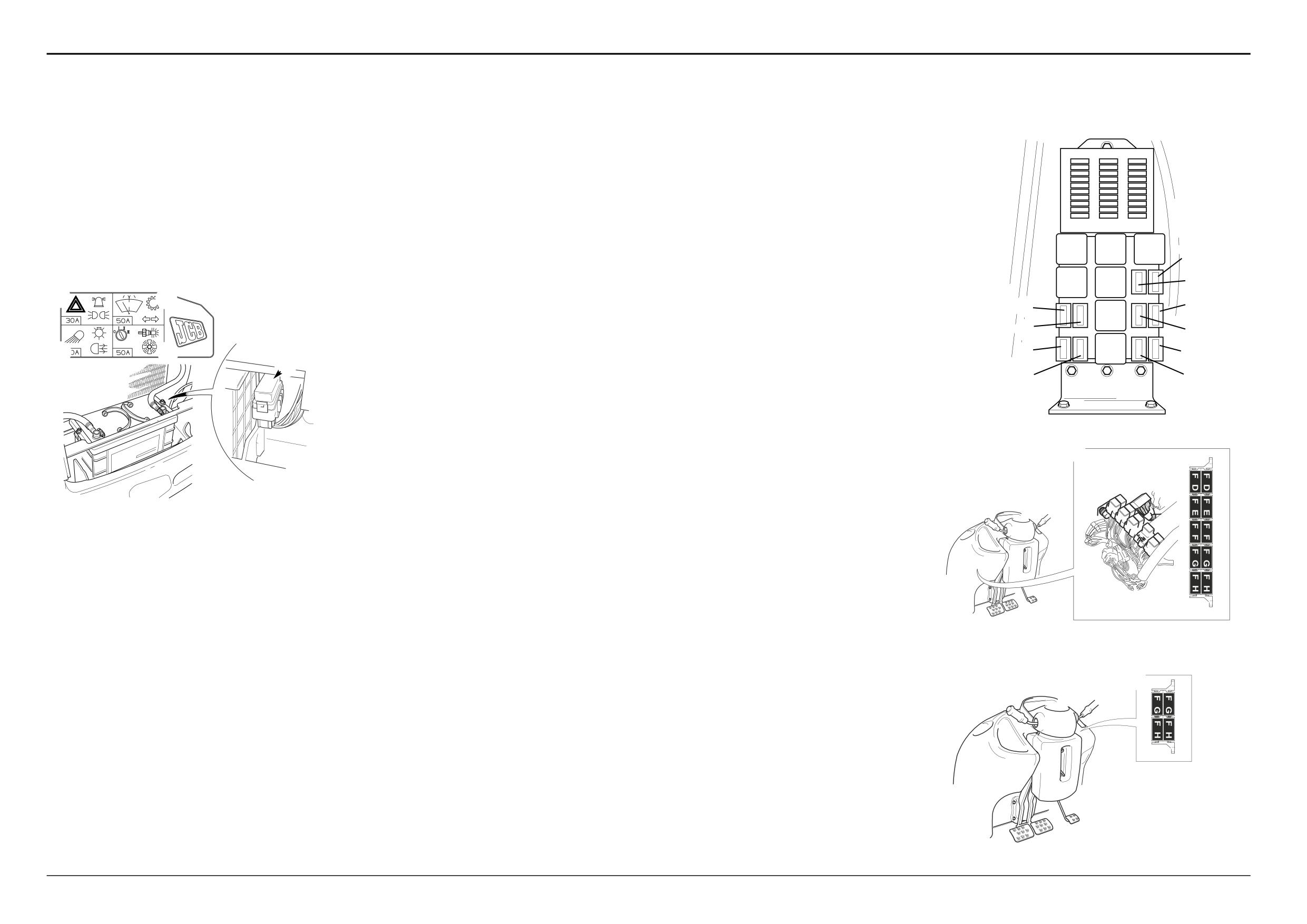
To further protect the machine wiring harnesses and
4 speed Powershift / Synchro Shuttle
10
10
10
9
9
9
electrical circuits, a fuse link box is fitted to the battery, as
The relays listed below are located in the side console
The relays listed below are located in the front console as
8
8
8
7
7
7
shown at B. Remember to check the main circuit fuses as
underneath cover A.
shown at C.
6
6
6
5
5
5
well as the link box fuses shown on this page.
4
4
4
3
3
3
1
Ignition 1
FD1
Forward HI/LO
2
2
2
1
Hazard warning lights, Beacon, Lights
30 Amp
2
Hammer
FD2
Forward
1
1
1
2
Wash/Wipe, Transmission, Indicators
50 Amp
3
Auxiliary (jaw bucket)
FE1
Reverse HI/LO
C
B
A
3
Work lights, Fog Lights, Brake lights
50 Amp
4
Main lights
FE2
Reverse
4
Ignition, Heater, Thermostart
50 Amp
5
Engine run
FF1
Interlock
@
8
1
6
Hydraulic speed control (HSC)
FF2
Drive
2
*
7
Buzzer (from serial no. 933757 only)
FG1
Blank
8
Buzzer
FG2
Transmission dump
£
9
3
1
2
9
Ignition 2
FH1
Auto 2WD
10
Front working lights
FH2
4WB
$
4
11
Rear working lights
0
12
Direction indicator
%
5
13
Neutral start
!
3
4
^
6
*
14
Rear horn
B
*
15
Parking brake warning light
&
7
16
Air conditioning compressor
*
17
Parking brake (from serial no. 933757 only)
396500
6 speed Powershift (Shiftmaster)
The relays listed below are located in the side console
The relays listed below are located in the front console as
underneath cover A.
shown at D.
C
A396480
1
Ignition 1
FG1
Reverse Alarm
2
Hammer
FG2
Transmission dump
3
Auxiliary (jaw bucket)
FH1
2WB
4
Main lights
FH2
Brake lights
5
Engine run
6
Hydraulic speed control (HSC)
Note: Relay base positions may vary from those shown at D.
*
7
Buzzer
Compare wire numbers on the relevant front consloe
8
Buzzer
harness drawing to confirm relay identification
9
Ignition 2
10
Front working lights
11
Rear working lights
12
Direction indicator
13
Neutral start
*
14
Rear horn
A405390
*
15
Parking brake warning light
16
Air conditioning compressor
*
17
Parking brake
D
A405400
9803/3280
Issue 3*
Section C
Electrics
Section C
4-1
Basic System Operation
4-1
Circuit Schematic - Basic Machine
20
22
859
EARTH
2
24
25
51
52
53
54
55
56
LH
9
11
SPEAKER
16
21
23
601
860
7
57
10
RH
SPEAKER
3
8
W
58
412
602
1
407
805
407
C
6
401
D
42
420
411
15
FRONT CONSOLE
INSTRUMENTS
40
7
2
19
5
1
18
2
4
14
5
2
5
43
43
43
43
8
6
3
1
26
27
28
29
44
45
46
47
48
49
50
B
30
32
33
34
35
36
37 38
39
41
810
A
SIDE CONSOLE
31
INSTRUMENTS
830
830
835
E
17
8
5
17
2
806
855
F
861
G
837
H
10
18
1
3
4
2
12
4
2
13
830
J
6
8
6
8
002
200
200
K
4
001
007
L
002
M
133
N
001
P
Q
A409180
852/30241sht1 Iss1
9803/3280
Issue 3*
Section C
Electrics
Section C
4-2
Basic System Operation
4-2
Circuit Schematic - Basic Machine
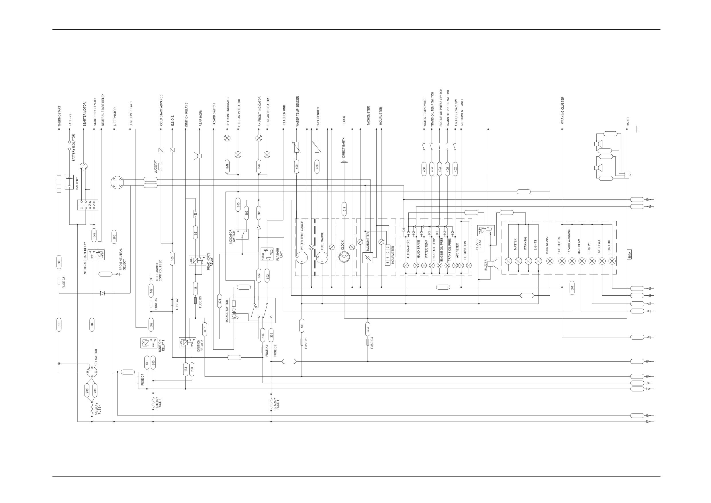
Refer to pages C/4-1 and C/4-4.
The basic circuit shows a standard machine. The remaining pages in section C/4 show machine circuits that differ from the
‘basic’. Note that ONLY the differences are shown.
*
Main Components:
1
Thermostart
51
Engine Coolant Temperature Switch
2
Battery Isolator
52
Transmission Oil Temperature Switch
3
Battery
53
Engine Oil Pressure Switch
4
Starter Switch
54
Transmission Oil Pressure Switch
5
Neutral Start Relay
55
Air Filter Restriction Switch
6
Starter Solenoid
56
LH Speaker
7
Starter Motor
57
RH Speaker
8
Alternator
58
Radio (if fitted)
9
Cold Start Advance Solenoid
10
Cold Start Advance Switch
*
Connections:
11
Engine Shut-Off Solenoid (ESOS)
A
From A on page C/4-5 and C/4-13 as applicable
12
Ignition Relay ‘1’
B
To B on page C/4-5
13
Ignition Relay ‘2’
C
To C on page C/4-4
14
Rear Horn Relay
D
From D on page C/4-5 and C/4-13 as applicable
15
Rear Horn Switch
E
From E on page C/4-4
16
Rear Horn
F
From F on page C/4-4
17
Hazard Warning Switch
G
From G on page C/4-4
18
Indicator Flasher Unit
H
From H on page C/4-4
19
Direction Indicator Switch
J
From J on page C/4-4
20
LH Front Indicator
K
To K on page C/4-4
21
LH Rear Indicator
L
To L on page C/4-4 and C/4-8, and C/4-13
22
RH Front Indicator
as applicable
23
RH Rear Indicator
M
To M on page C/4-8 and C/4-13 as applicable
24
Engine Coolant Temperature Sender
N
To N on page C/4-4
25
Fuel Gauge Sender
P
To P on page C/4-4
26
Engine Coolant Temperature Gauge
Q
To Q on page C/4-4
27
Fuel Gauge
28
Clock
29
Tachometer
30
Hourmeter
31
Side Instrument Console
32
Alternator Warning Indicator Light
33
Parking Brake Indicator Light
34
Engine Coolant Temperature Indicator Light
35
Transmission Oil Temperature Indicator Light
36
Engine Oil Pressure Indicator Light
37
Transmission Oil Pressure Indicator Light
38
Air Filter Blocked Indicator Light
39
Panel Illumination
40
Warning Buzzer Relay
41
Warning Buzzer
42
Front Instrument Console
43
Master Warning Lights
44
Turn Signal Indicator
45
Side Lights Indicator
46
Hazard Warning Indicator
47
Main Beam Warning Indicator Light
48
Rear Working Light Indicator
49
Front Working Light Indicator
50
Rear Fog Light Indicator
9803/3280
Issue 3*
Section C
Electrics
Section C
4-3
Basic System Operation
4-3
Circuit Schematic - Basic Machine (cont’d)
*
Main Components:
*
Connections:
59
Cigar Lighter
C From C on page C/4-1
60
Face Level Fan
E To E on page C/4-1
61
Face Level Fan Switch
F To F on page C/4-1
62
Heated Seat
G To G on page C/4-1
63
Heated Seat Switch
H To H on page C/4-1
64
Rear Washer/Wiper Switch
J
To J on page C/4-1 and C/4-9
65
Rear Wiper Motor
K
From K on page C/4-1
66
Rear Washer Motor
L
From L on page C/4-1
67
Front Washer/Wiper Switch
N
From N on page C/4-1
68
Front Washer Motor
P
From P on page C/4-1
69
Front Wiper Intermittent Electronic Control Unit
Q
From Q on page C/4-1
70
Front Wiper Motor
R
To R on page C/4-9
71
Head Light Flasher Switch
Fuses:
72
Front Horn Switch
A1 - A10
73
Front Horn
B1 - B10
74
Rear Fog Light Switch
C1 - C10
75
Rear Fog Light
76
Removed For Territories - Italy, Germany
Refer to Technical Data pages at the beginning of Section C
77
Fitted For Territories - Italy, Germany
for further fuse details and ratings.
78
Road Lights Relay
79
Road Lights Switch
80
Head Light Dip Switch
81
LH Main Beam Light
82
RH Main Beam Light
83
LH Dip Beam Light
84
RH Dip Beam Light
85
LH Tail Light
86
LH Side Light
87
Socket (Dipper Light)
88
Number Plate Light
89
RH Tail Light
90
RH Side Light
91
Engine Running Relay
92
Front Working Lights Relay
93
Rear Working Lights Relay
94
Front Working Lights Switch
95
Rear Working Lights Switch
96
Front Working Lights
97
Rear Working Lights
98
Cab Interior Light/Switch
99
Beacon Switch
100
Beacon
101
Heater Switch
102
Heater Motor
103
Heater Resistor
104
Air Conditioning Pressure Switches
105
Air Conditioning Compressor Solenoid
9803/3280
Issue 3*
Section C
Electrics
Section C
4-4
Basic System Operation
4-4
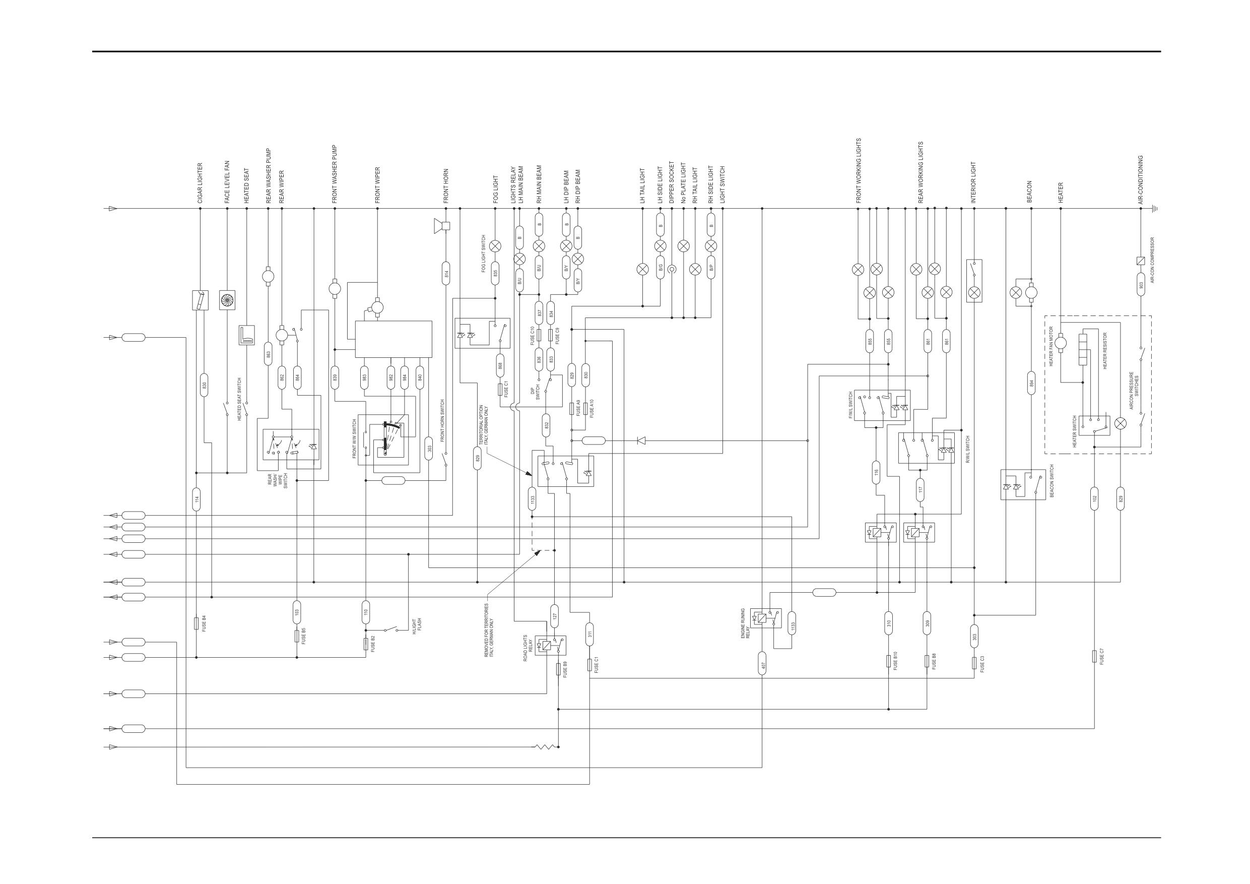
Circuit Schematic - Basic Machine (cont’d)
73
75
82
86
88
90
81
84
105
83
98
85
89
96
66
M
68
87
100
59
60
M
M
70
97
M
7
74
3
62
65
102
M
INTEGRAL
C
407
69
INTERMITTENT
ECU
M
8
2
104
103
94
6
3
7
80
61
63
67
101
5
2
5
2
64
7
4
6
1
3
7
828
77
4
6
3
7
6
1
3
8
72
ROAD
5
2
8
7
3
LIGHTS
95
SWITCH
110
5
2
79
8
2
99
E
835
4 2
4 2
F
855
92
93
861
G
6
8
6
8
H
837
R
829
1853
J
830
76
91
5 2
71
7810
7
3
1
K
200
L
007
8
6
N
133
P
001
Q
PRIMARY
FUSE 2
A409181
852/30241sht2 Iss1
9803/3280
Issue 3*
www.WorkshopManuals.co.ukElectrics
Section C
Section C
4-5
Basic System Operation
4-5
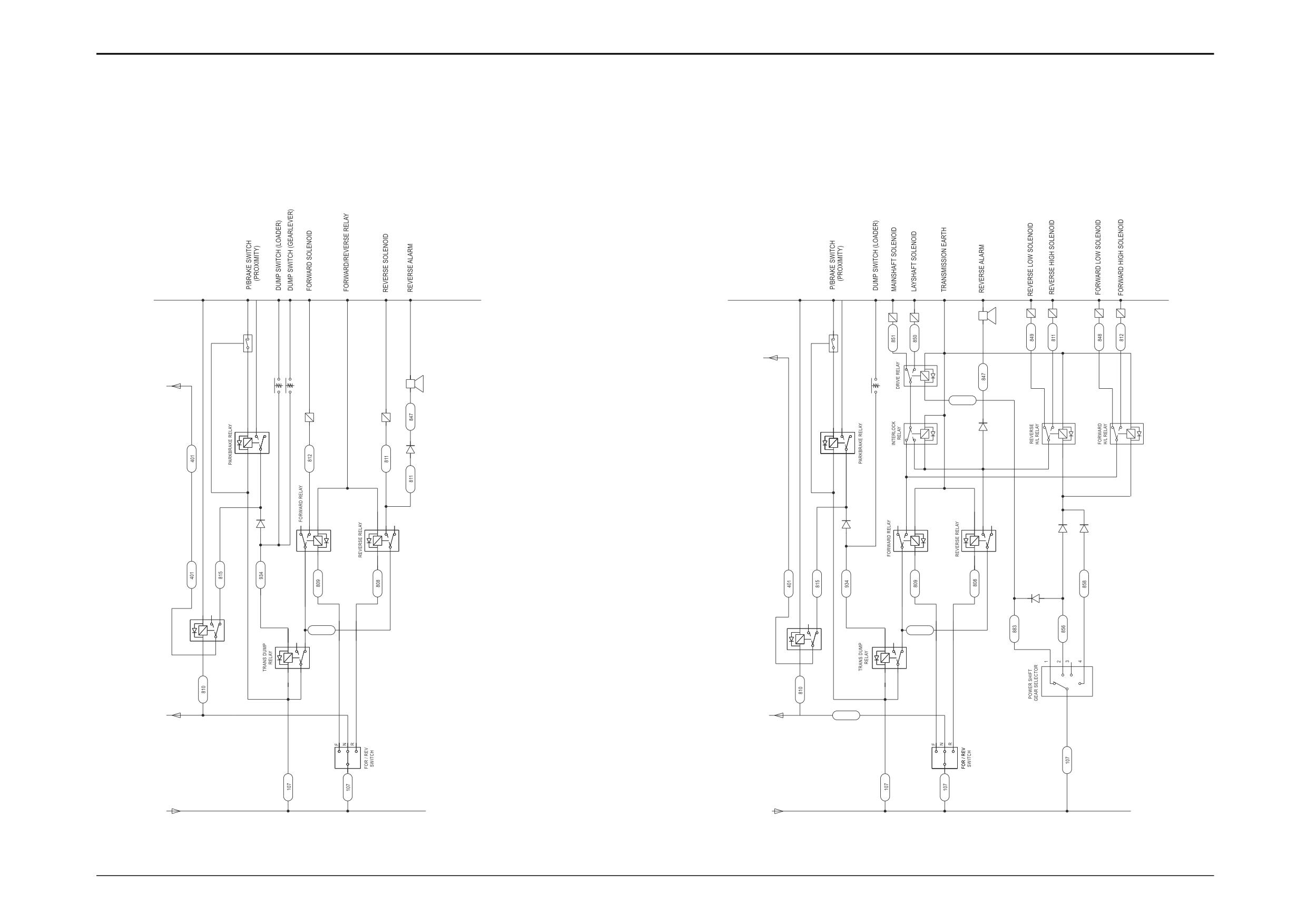
Circuit Schematic - Synchro Shuttle
Circuit Schematic - Powershift
Note: For further details on Powershift gearbox electrical circuits and connections, refer to
Section F - Electrical Connections.
Synchro Shuttle Transmission
4 Speed Powershift Transmission
7
8
15
17
18
20
12
3
3
D
4
2 5
5
6
12
5
6
D
1
3
883
7
10
9
16
19
1
5
9
7
10
9
7
10
2
10
7
10
7
2
4
2
3
6
8
6
8
8
6
8
6
10
2
5
10
7
2
5
10
7
13
11
81
3
8
6
1
3
8
6
10
9
1
1
852
852
8
6
4
5
4
45
4
3
1
3
1
14
A
A
810
TO NEUTRAL
TO NEUTRAL
START RELAY
START RELAY
9
11
B
B
TO FUSE
TO FUSE
A5
852/30241sht3 Iss1
A5
852/30241sht3 Iss1
A409182
A409182
9803/3280
Issue 3*
Section C
Electrics
Section C
4-6
Basic System Operation
4-6
Circuit Schematic - Synchro Shuttle and
Powershift
*
Synchro Shuttle Transmission
*
4 Speed Powershift Transmission
1
Parking Brake Warning Light Relay
1
Parking Brake Warning Light Relay
2
Parking Brake Relay
2
Parking Brake Relay
3
Parking Brake Switch
3
Parking Brake Switch
4
Transmission Dump Relay
4
Transmission Dump Relay
5
Transmission Dump Switch on Loader Lever
5
Transmission Dump Switch on Loader Lever
6
Transmission Dump Switch on Gear Lever
6
Drive Relay
7
Forward Solenoid
7
Mainshaft Solenoid
8
Forward Relay
8
Layshaft Solenoid
9
Forward/Reverse Selector Lever
9
Interlock Relay
10
Reverse Solenoid
10
Forward Relay
11
Reverse Relay
11
Forward/Reverse Selector Lever
12
Reverse Alarm
12
Reverse Alarm
13
Reverse Relay
Connections:
14
Gear Selector Switch
A To A on page C/4-1
15
Reverse Low Solenoid
B From B on page C/4-1
16
Reverse High/Low Relay
D To D on page C/4-1
17
Reverse High Solenoid
18
Forward Low Solenoid
19
Forward High/Low Relay
20
Forward High Solenoid
Connections:
A To A on page C/4-1
B From B on page C/4-1
D To D on page C/4-1
9803/3280
Issue 2*
Section C
Electrics
Section C
4-7
Basic System Operation
4-7
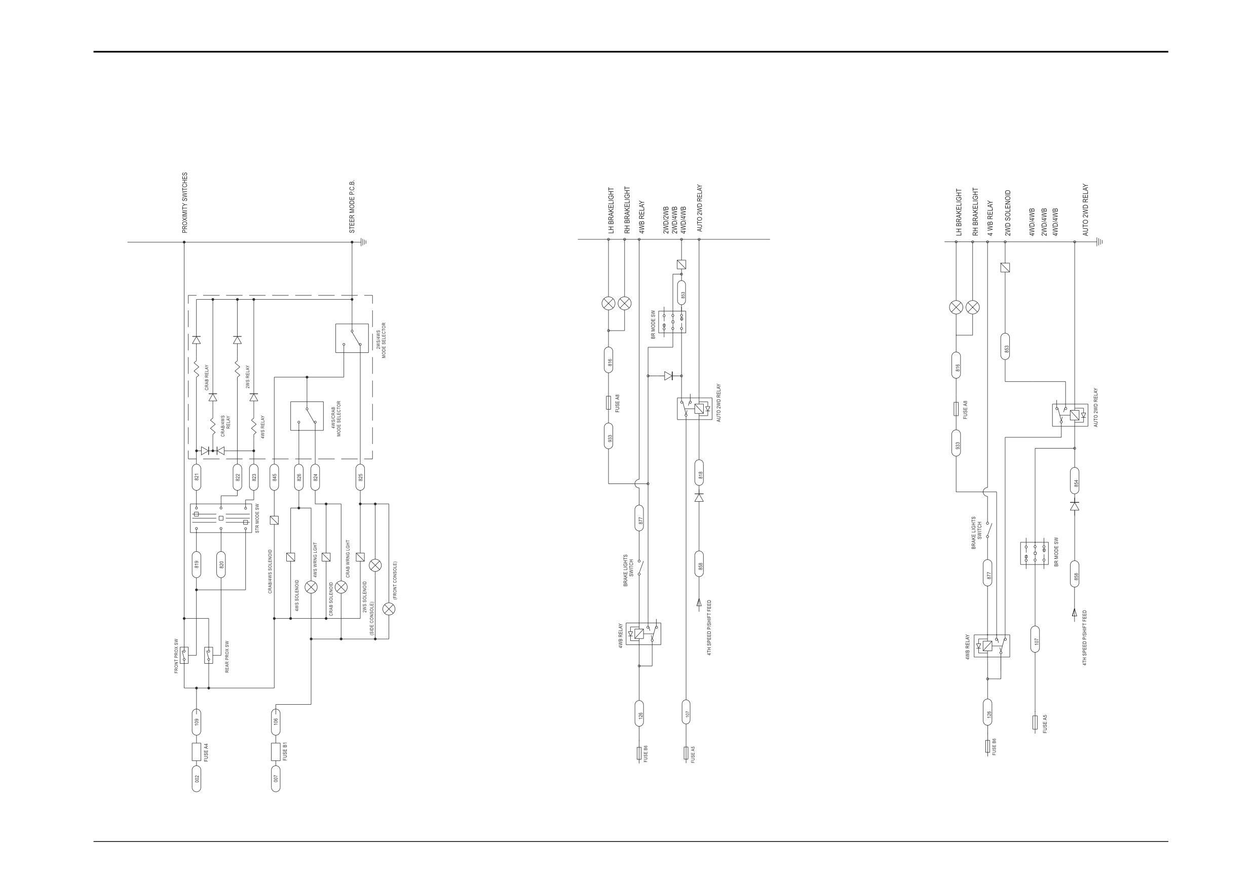
Circuit Schematics - Options
Steer Mode - 4CX and 3CX Super (4x4x4)
1
Front Axle Proximity Switch
2
Rear Axle Proximity Switch
3
Steer Mode Selector Switch
4
Steer Mode Printed Circuit Board
5
Crab Relay
6
Crab/4 Wheel Steer Relay
7
2 Wheel Steer Relay
8
4 Wheel Steer Relay
9
4 Wheel Steer/Crab Mode Selector (part of 4)
10
2 Wheel Steer/4 Wheel Steer Mode Selector (part of 4)
11
Crab/4 Wheel Steer Solenoid
12
4 Wheel Steer Solenoid
13
4 Wheel Steer Indicator Light
14
Crab Solenoid
15
Crab Indicator Light
16
2 Wheel Steer Solenoid
17
2 Wheel Steer Indicator Light (Side Console)
18
2 Wheel Steer Indicator Light (Front Console)
Connections:
*
L From L on page C/4-1
M From M on page C/4-1
2 Wheel Steer/Brake Mode
2 Wheel Steer/Brake Mode (Germany)
*
*
1
LH Brake Light
1
LH Brake Light
2
RH Brake Light
2
RH Brake Light
3
Brake Light Switch
3
Brake Light Switch
4
4 Wheel Braking Relay
4
4 Wheel Braking Relay
5
Brake Mode Selector Switch
5
2 Wheel Drive Solenoid
6
4 Wheel Drive/4 Wheel Braking Solenoid
6
Brake Mode Selector Switch
7
Auto 2 Wheel Drive Relay
7
Auto 2 Wheel Drive Relay
Connections:
Connections:
S From 14 on page C/4-5 and 9 on C/4-13 as applicable
S From 14 on page C/4-5 and 9 on C/4-13 as applicable
9803/3280
Issue 2*
www.WorkshopManuals.co.ukElectrics
Section C
Section C
4-8
Basic System Operation
4-8
Circuit Schematics - Options
Steer Mode - 4CX and 3CX Super (4x4x4)
2 Wheel Steer/Brake Mode
2 Wheel Steer/Brake Mode (Germany)
6
5
1
2
1
2
5
4
STEER MODE
P.C.B.
5
7
10
9 7
10
7
10
6
8
6
8
7
6
8
9
7
3
11
3
12
14
16
3
17
6
13
15
4 5
2
4
18
S
4
5
2
4
S
1
2
3
1
3
1
M
L
852/30241sht3 Iss1
852/30241sht4 Iss1
852/30241sht6 Iss1
IGNITION RELAY 1
IGNITION RELAY 2
A409182
A409183
A409185
9803/3280
Issue 2*
www.WorkshopManuals.co.ukElectrics
Section C
Section C
4-9
Basic System Operation
4-9
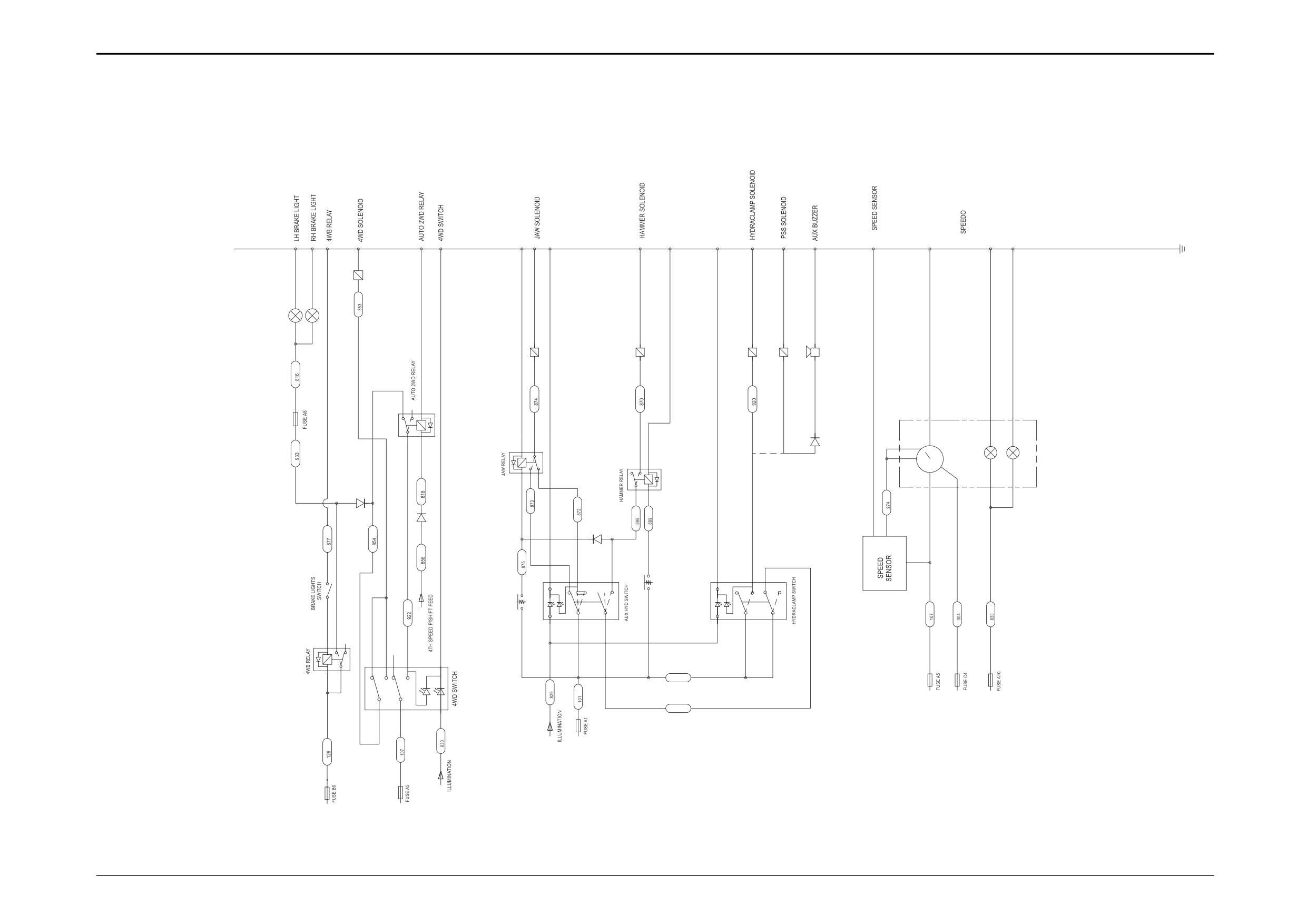
Circuit Schematics - Options
All Wheel Steer/Brake Mode
Auxiliary and Hydraclamp Hydraulics
Speedometer
5
1
2
3
5
9
10
11
9
7
10
6
6
8
2
3
1
5
1
6
7
10
3
2
4
6
8
1
3
7
8
1
3
6
8
3
4
2
S
7
2
5
7
2
5
4
8
4
5
2
4
4
6
1
3
7
3
1
101
1830
5
2
8
7
R
J
A409183
852/30241sht4 Iss1
9803/3280
Issue 2*
Section C
Electrics
Section C
4 - 10
Basic System Operation
4 - 10
Circuit Schematics - Options
*
All Wheel Steer/Brake Mode
1
LH Brake Light
2
RH Brake Light
3
Brake Light Switch
4
4 Wheel Braking Relay
5
4 Wheel Drive Solenoid
6
Auto 2 Wheel Drive Relay
7
4 Wheel Drive Selector Switch
Connections:
J
From J on page C/4-4
S
From 14 on page C/4-5 and 9 on C/4-13 as applicable
Auxiliary and Hydraclamp Hydraulics
1
Jaw Relay
2
Push-Button Switch on Excavator Lever
3
Jaw Solenoid
4
Auxiliary Hydraulics Selector Switch
5
Hammer Solenoid
6
Hammer Relay
7
Footpedal Switch
8
Hydra-clamp Selector Switch
9
Hydra-clamp Solenoid
10
Power Sideshift Solenoid (if fitted)
11
Warning Buzzer
Connections:
R From R on page C/4-4
Speedometer Option
1
Speed Sensor
2
Speedometer
3
Illumination
9803/3280
Issue 2*
Section C
Electrics
Section C
4 - 11
Basic System Operation
4 - 11
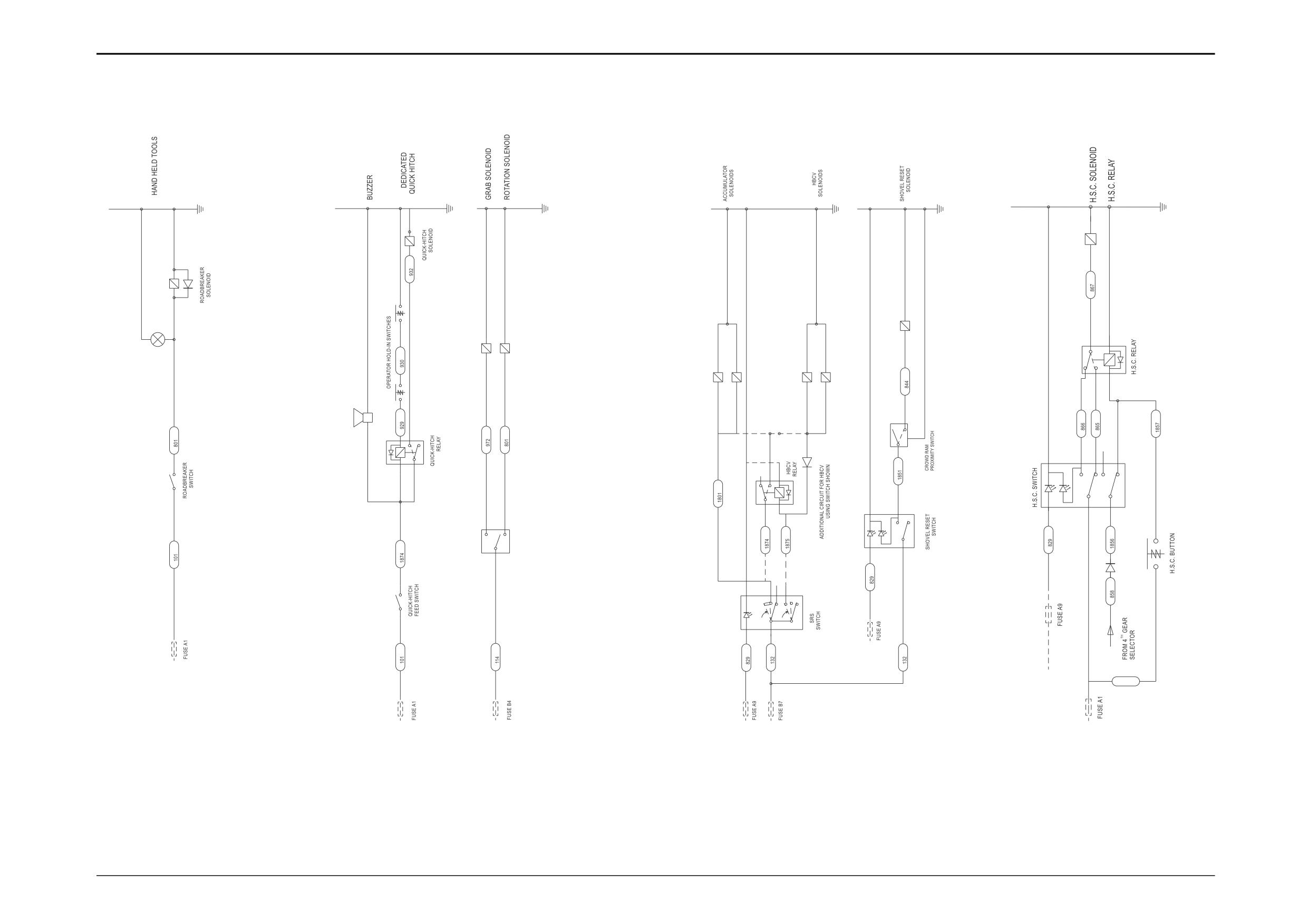
Circuit Schematics - Options
*
Hand Held Tools
1
Selector Switch
2
Indicator Lamp
3
Roadbreaker Solenoid
*
Dedicated Quickhitch
1
Hitch Enable Switch
2
Quick-Hitch Relay
3
Warning Buzzer
4
Lever ‘hold-in’ Button
5
Lever ‘hold-in’ Button
6
Quick-Hitch Solenoid
*
Pole Planter
1
Selector Switch
2
Grab Solenoid
3
Rotation Solenoid
*
Smooth Ride System (SRS)
1
Accumulator Solenoids
2
Hose Burst Control Valve Relay (if fitted)
3
Selector Switch
4
Hose Burst Control Valve Solenoids (if fitted)
*
Return to Dig (Shovel Reset)
5
Lever ‘hold-in’ Solenoid
6
Ram Proximity Switch
7
Selector Switch
*
Hydraulic Speed Control (HSC)
1
Selector Switch
2
HSC Solenoid
3
HSC Relay
4
Control Lever Push-Button
Connections:
S From 14 on page C/4-5 and 9 on C/4-13 as applicable
9803/3280
Issue 2*
Section C
Electrics
Section C
4 - 12
Basic System Operation
4 - 12
Circuit Schematics - Options
6
2
3
5
5
2
2
3
6
10
1
4
9
7
8
3
4
3
6
1
7
3
1
6
4
2
2
1
7
3
8
2
5
1
8
2
4
7
7
3
1
6
1
8
2
5
3
S
101
A409185
A409185
852/30241sht6 Iss1
852/30241sht6 Iss1
Hand Held Tools
Dedicated Quick-Hitch
Pole Planter
Smooth Ride System
Return To Dig
Hydraulic Speed Control
(SRS)
(Shovel Reset)
(HSC)
9803/3280
Issue 2*
Section C
Electrics
Section C
4 - 13
Basic System Operation
4 - 13
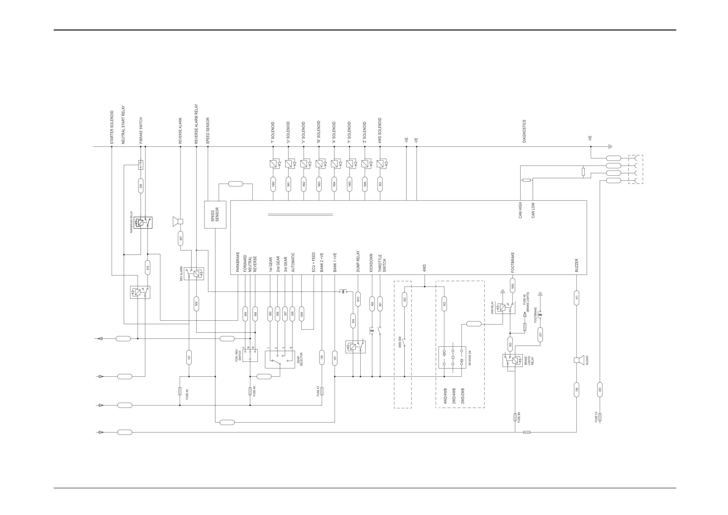
Circuit Schematics - 6 Speed Powershift (Shiftmaster)
Note: For further details on Powershift gearbox electrical circuits and connections, refer to
Section F - Electrical Connections.
10
11
12
13
14
15
16
17
600
3
500
120 Ohm
120 Ohm
RESISTOR
501
RESISTOR
303
974
28
6
7
AUTOSHIFT ECU
10
7
2
4
8
6
7
10
5
6
8
110
9
18
2410 9
8
6
26
8
6
909
TO NEUTRAL
20
21
START RELAY
22
A
810
810
19
5
2
4
4 2
5
3
1
27
8
FROM PARKBRAKE
1
3
WARNING LIGHT
9
23
25
D
401
135
FROM IGNITION
RELAY 1
M
002
AWS ONLY
2WS ONLY
107
FROM IGNITION
RELAY 2
FUSE B1
L
007
A409184
852/30241sht5 Iss1
9803/3280
Issue 2*
Section C
Electrics
Section C
4 - 14
Basic System Operation
4 - 14
*
Circuit Schematic
- 6 Speed Powershift (Shiftmaster)
6 Speed Powershift Transmission
1
Parking Brake Warning Light Relay
2
Parking Brake Relay
3
Parking Brake Switch
4
Reverse Alarm
5
Reverse Alarm Relay
6
Speed Sensor
7
Electronic Control Unit
8
Forward/Reverse Selector Lever
9
Gear Selector Switch
10
Solenoid ‘T’
11
Solenoid ‘U’
12
Solenoid ‘V’
13
Solenoid ‘W’
14
Solenoid ‘X’
15
Solenoid ‘Y’
16
Solenoid ‘Z’
17
4 Wheel Drive Solenoid
18
Transmission Dump Switch
19
Transmission Dump Relay
20
Kick-down Switch
21
Throttle Switch
22
4 Wheel Drive Switch
23
Brake Mode Selector Switch
24
2 Wheel Braking Relay
25
Brake Lights Relay
26
Footbrake Switch
27
Warning Buzzer
28
Diagnostics Connector
Connections:
A To A on page C/4-1
D To D on page C/4-1
M From M on page C/4-1
L From L on page C/4-1
9803/3280
Issue 2*
Section C
Electrics
Section C
4 - 15
Basic System Operation
4 - 15
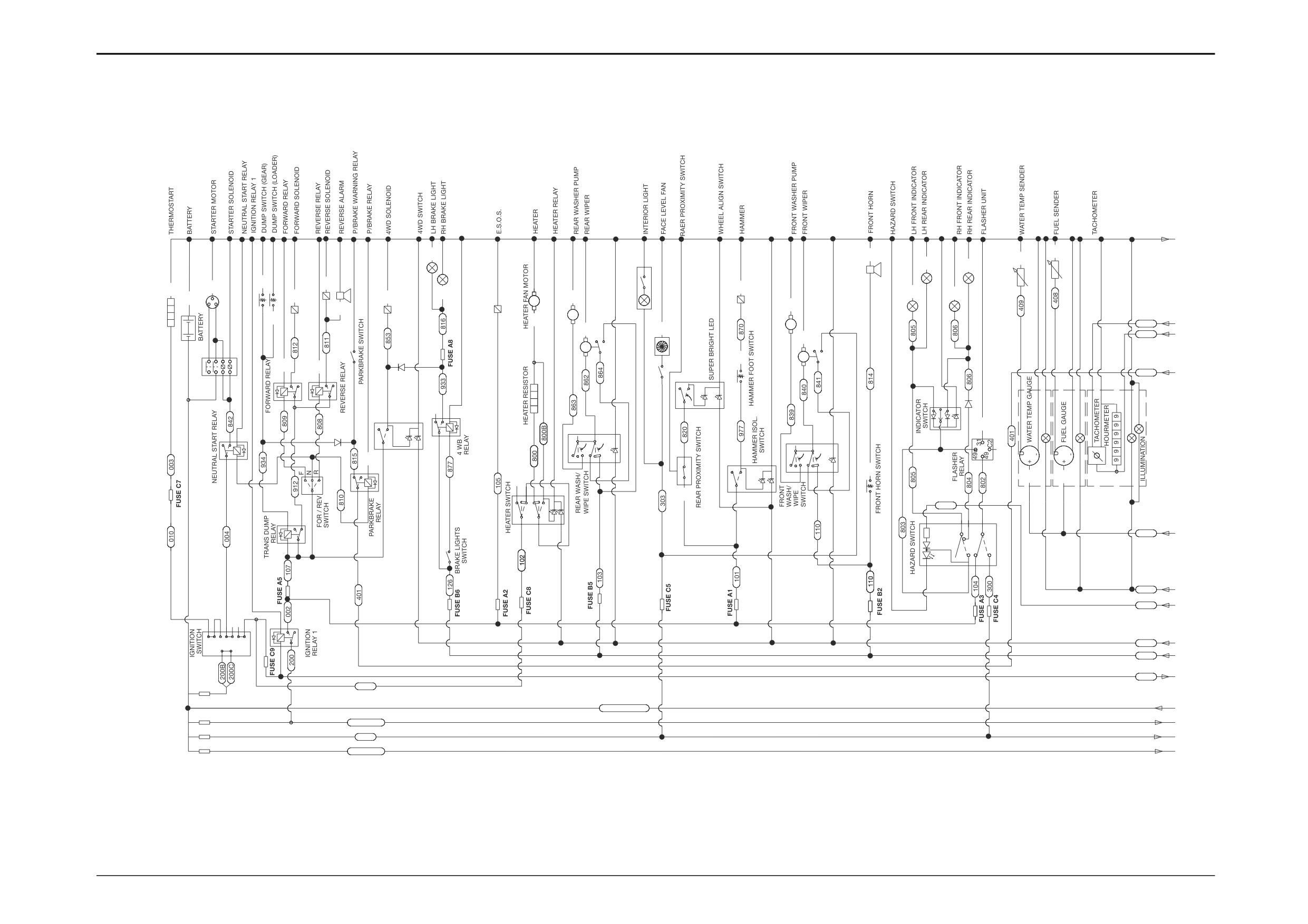
Circuit Schematic - 214e Machines
Refer to pages C/4-16 and C/4-17.
Main Components:
1
Thermostart
51
Engine Coolant Temperature Gauge
2
Battery
52
Engine Coolant Temperature Sender
3
Starter Switch
53
Fuel Gauge
4
Neutral Start Relay
54
Fuel Gauge Sender
5
Starter Solenoid
55
Tachometer
6
Starter Motor
56
Hourmeter
7
Ignition Relay ‘1’
8
Transmission Dump Relay
Connections:
9
Forward/Reverse Selector Lever
A
To A on page C/4-17
10
Forward Relay
B
From B on page C/4-17
11
Reverse Relay
C
From C on page C/4-17
12
Forward Solenoid
D
From D on page C/4-17
13
Reverse Solenoid
E
From E on page C/4-17
14
Reverse Alarm
F
From F on page C/4-17
15
Transmission Dump Switch on Gear Lever
G
From G on page C/4-17
16
Transmission Dump Switch on Loader Lever
H
From H on page C/4-17
17
Parking Brake Relay
J
From J on page C/4-17
18
Parking Brake Switch
K
To K on page C/4-17
19
4 Wheel Drive Selector Switch
L
From L on page C/4-17
20
4 Wheel Drive Solenoid
M
To M on page C/4-17
21
Brake Light Switch
N
To N on page C/4-17
22
4 Wheel Braking Relay
P
To P on page C/4-17
23
LH Brake Light
24
RH Brake Light
25
Engine Shut-Off Solenoid (ESOS)
26
Heater Switch
27
Heater Resistor
28
Heater Fan Motor
29
Rear Washer/Wiper Switch
30
Rear Washer Motor
31
Rear Wiper Motor
32
Cab Interior Light/Switch
33
Face Level Fan/Switch
34
Rear Proximity Switch
35
Wheel Align Switch
36
Hammer Isolaton Switch
37
Hammer Foot Switch
38
Hammer Solenoid
39
Front Washer/Wiper Switch
40
Front Washer Motor
41
Front Wiper Motor
42
Front Horn Switch
43
Front Horn
44
Hazard Warning Switch
45
Indicator Flasher Unit
46
Direction Indicator Switch
47
LH Front Indicator
48
LH Rear Indicator
49
RH Front Indicator
50
RH Rear Indicator
9803/3280
Issue 1
Section C
Electrics
Section C
4 - 16
Basic System Operation
4 - 16
Circuit Schematic - 214e Machines
A
5
4
2
3
4
3
52
4
8
5
0
1
5
1
3
1
6
38
2
4
32
4
7
49
2
1
2
2
0
30
M
40
14
25
M
16
2
8
M
412
B
31
3
3
407
C
41
18
M
M
37
10
11
401
D
5
2
4
10
7
9
3
35
7
5
27
56
3
1
8
6
1
3
7
9
710
2
8
3
19
7
22
29
4
5
5
2
7
2
5
2
4
39
6
6
8
5
2
7
46
4
2
8
36
2
1
7
3
7
4
8
6
6
1
3
8
9
7
10
42
6
1
3
8
26
5
1
5
3
55
9
1
3
4
6
7
6
8
3
4
2
8
828
5
2
4
8
5
17
2
2
5
8
106
E
3
1
8
21
10
18
1
3
44
830
F
828
G
4
2
5
9873456
829
H
1
2
6
8
007
J
3
7
011
K
001
FUSE P3
BATTERY FEED
L
FUSE P2
200D/200M
M
FUSE P1
200G
N
FUSE P4
200E/200R
P
FUSE P1 40A
FUSE P2 50A
FUSE P3 50A
FUSE P4 60A
331/17034sht 1
9803/3280
Issue 1
Section C
Electrics
Section C
4 - 17
Basic System Operation
4 - 17
Circuit Schematic - 214e Machines (cont’d)
OPTIONS
A
6
062646
668
8
6
8
9
9
2
84
71
80
85
72
7
6
87
70
7
9
8
8
9
0
91
B
412
W
C
407
407
102
411
D
401
16
3
18
12
9
11
10
17
69
6
3
7
1
3
83
7
3
7
4
6
1
3
7
57
5859616
365
67
5
2
75
2
8
2
8
5
2
8
101
78
SIDE CONSOLE
7
INSTRUMENTS
744
2
5
4
2
5
6
3
7
106
6
8
6
8
E
77
5
2
82
F
830
G
828
H
4 2
5
H
829
5
2
4
6
8
'SRS'
007
8
1
SMOOTH RIDE
J
SYSTEM
738
6
011
100
K
L
BATTERY FEED
M
200D/200M
N
200G
P
200E/200R
331/17034sht 2
9803/3280
Issue 1
Section C
Electrics
Section C
4 - 18
Basic System Operation
4 - 18
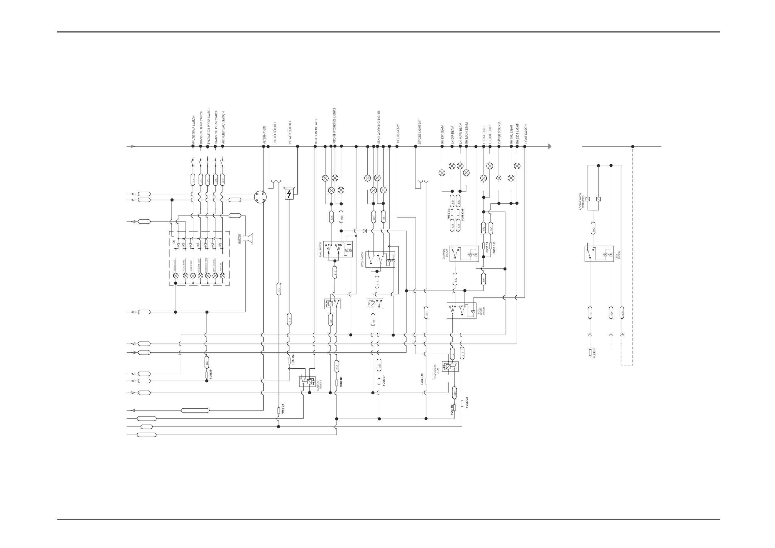
Circuit Schematic - 214e Machines (cont’d)
Main Components:
Connections:
57
Alternator Warning Indicator Light
A From A on page C/4-16
58
Parking Brake Indicator Light
B To B on page C/4-16
59
Engine Coolant Temperature Indicator Light
C To C on page C/4-16
60
Engine Coolant Temperature Switch
D To D on page C/4-16
61
Transmission Oil Temperature Indicator Light
E To E on page C/4-16
62
Transmission Oil Temperature Switch
F To F on page C/4-16
63
Engine Oil Pressure Indicator Light
G To G on page C/4-16
64
Engine Oil Pressure Switch
H To H on page C/4-16
65
Transmission Oil Pressure Indicator Light
J
To J on page C/4-16
66
Transmission Oil Pressure Switch
K
From K on page C/4-16
67
Air Filter Blocked Indicator Light
L
To L on page C/4-16
68
Air Filter Restriction Switch
M
From M on page C/4-16
69
Warning Buzzer
N
From N on page C/4-16
70
Alternator
P
From P on page C/4-16
71
Radio Socket
Fuses:
72
Cab Auxiliary Power Socket
A1 - A10
73
Ignition Relay ‘2’
B1 - B10
74
Front Working Lights Relay
C1 - C10
75
Front Working Lights Switch
76
Front Working Lights
Refer to Technical Data pages at the beginning of Section C
77
Rear Working Lights Relay
for further fuse details and ratings.
78
Rear Working Lights Switch
79
Rear Working Lights
80
Beacon/Strobe Light Socket
81
Road Lights Relay
82
Road Lights Switch
83
Head Light Dip Switch
84
RH Dip Beam Light
85
LH Dip Beam Light
86
LH Main Beam Light
87
RH Main Beam Light
88
LH Tail Light
89
LH Side Light
90
Socket (Dipper Light)
91
RH Tail Light
92
RH Side Light
Options:
100 SRS Smooth Ride System
101 Selector Switch
102 Accumulator Solenoids
9803/3280
Issue 1
Section C
Electrics
Section C
19 - 1
Service Procedures
19 - 1
Electrical Testing Methods
- Using a Multimeter
These instructions are intended to cover the use of the recommended multimeters.
A
OFF
V/A
A
V/A
B
C
A171900
S153070
1
Make sure that the test leads are plugged into the correct sockets. The black test lead should be plugged into the black
socket (sometimes, this socket is also marked by a " - ", or "E" or marked as "COMMON" or "COM"). The red test lead
should be plugged into the red socket marked with "+", "V" or "Ω".
2
When making measurements ensure that the test probes have a good clean contact with bare metal, free from grease,
dirt, and corrosion as these can cause a false reading.
3
When measuring voltage:
Make sure that the correct range is selected, that is set the selector to a value equal to or greater than that you are about
to measure.
e.g. If asked to measure 12 Volts, set the selector to the 12V range. If there is no 12V range, set the selector to the next
range higher, 20V for instance.
If the meter is set to a range that is too low, it may be damaged.
e.g. setting to the 2V range to measure 12V.
9803/3280
Issue 1
Section C
Electrics
Section C
19 - 2
Service Procedures
19 - 2
S153070
9803/3280
Issue 1
Section C
Electrics
Section C
19 - 3
Service Procedures
19 - 3
Electrical Testing Methods
- Using a Multimeter
1
Measuring DC Voltage
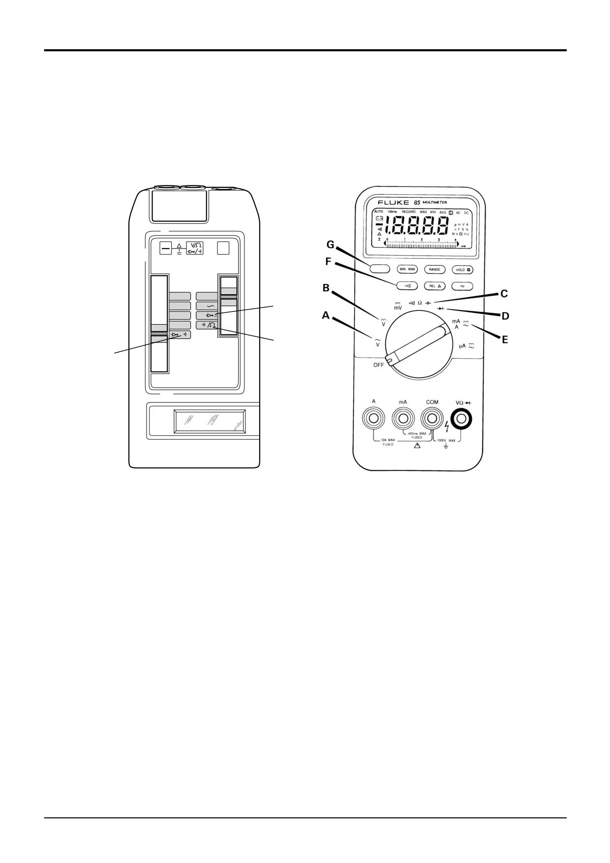
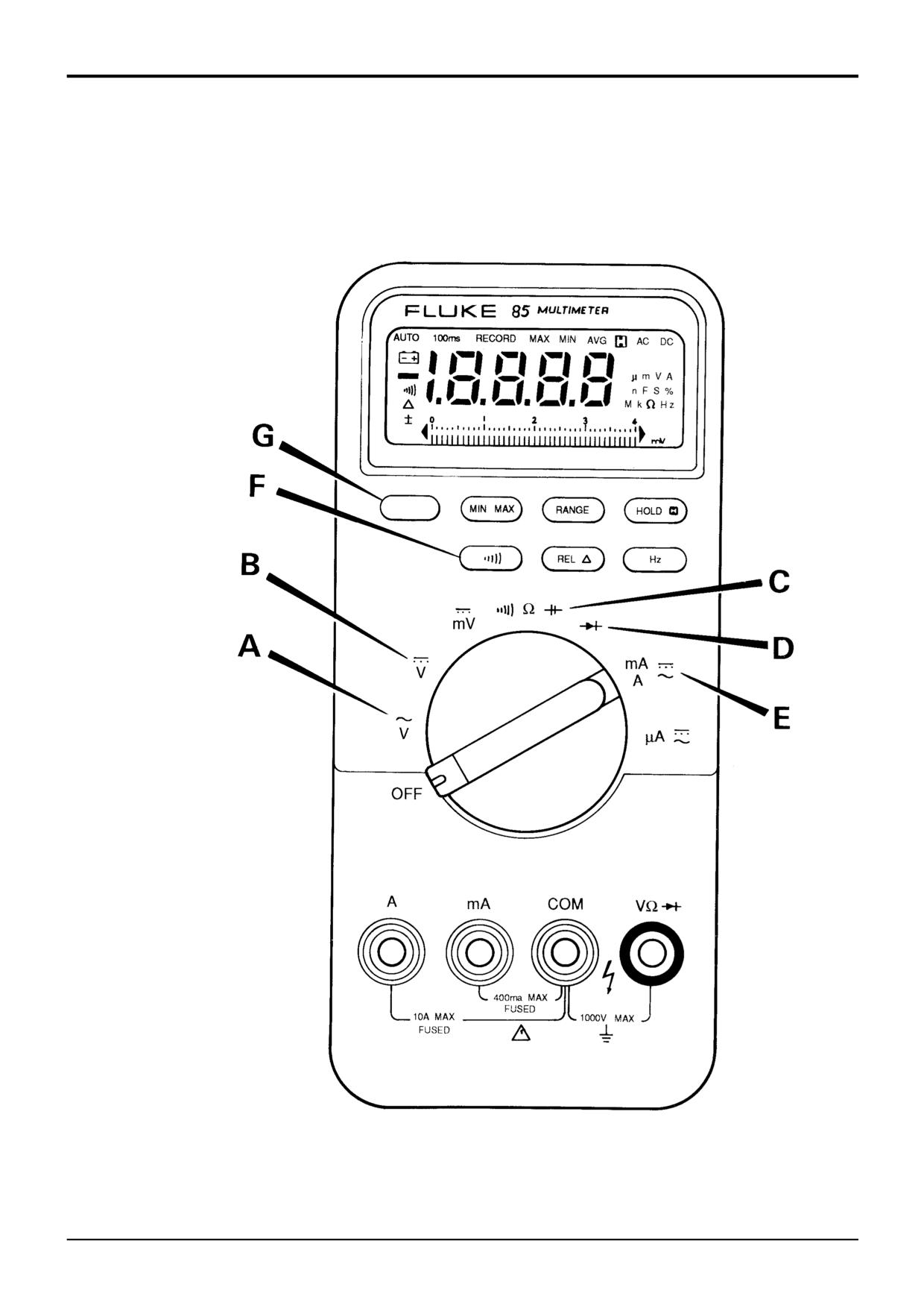
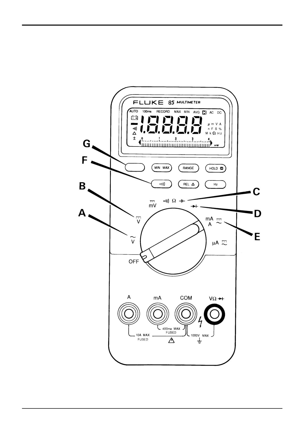
a On the FLUKE 85
Turn the switch to position B.
b On the AV0 2003
Move the right slider switch to position A, and the left hand slider switch to the appropriate range.
c On an analogue meter
Turn the dial to the appropriate DC Volts range.
Connect the black probe to the nearest available suitable earth point, usually this will be the starter motor earth, the battery
negative, or the chassis. Connect the red probe to the wire or contact from which you are measuring the voltage.
2
Measuring Resistance
Make sure there is no power to the part of the circuit you are about to measure.
Connect one probe at one end of the component or wire to be checked and the other probe at the other end. It does not
matter which way round the two probes are placed.
a On the FLUKE 85
Turn the switch to position C and check that the Ω sign at the right hand side of the display window is on. If the F
sign is on instead, press the blue button G to change the reading to Ω.
Touch the meter lead probes together and press the REL ³ key on the meter to eliminate the lead resistance from the
meter reading.
b On the AV0 2003
Move the right hand slider switch to position B, and the left hand slider switch to the appropriate Ohms (Ω) range.
c On an analogue meter
Move the dial to the appropriate Ohms (Ω) range.
3
Measuring Continuity
Make sure there is no power to the part of the circuit you are checking for continuity.
Connect one probe to one end of the component or wire to be checked and the other probe to the other end. It does not
matter which way round the two probes are placed.
a On the FLUKE 85
Turn the switch to position C and check that the beeper symbol appears at the left hand side of the display window.
If the F sign is on instead, press the button labelled F in the meter drawing.
If there is continuity in the circuit, the beeper will sound. If there is no continuity (open circuit), the beeper will not
sound.
b On the AV0 2003
Move the right hand slider switch to position B, and the left hand slider switch to position C.
If there is continuity (i.e. very low resistance) between two points the buzzer will sound.
c On an analogue meter
Turn the dial to the lowest Ohms (Ω) range.
If there is continuity (i.e. very low resistance) between two points the needle will move across fully (or almost fully) to
the right hand side of the scale.
9803/3280
Issue 1
Section C
Electrics
Section C
19 - 4
Service Procedures
19 - 4
9803/3280
Issue 1
Section C
Electrics
Section C
19 - 5
Service Procedures
19 - 5
Electrical Testing Methods
- Using a Multimeter
4
Testing a Diode or a Diode Wire
A diode wire is a diode with male connector fitted on one end and a female connector fitted on the other end. The diode is
sealed in heatshrink sleeving.
a
On the FLUKE 85
Turn the switch to position D.
Press the HOLD button and check that the H sign appears at the top right hand side of the display window.
Connect the black probe to the end of the diode with a band or to the male connector of the diode wire. Connect
the red probe to the other end of the diode or diode wire. If the beeper does not sound the diode or diode wire is
faulty.
Connect the red probe to the end of the diode marked with a band, or to the male connector of the diode wire, the
black probe should be connected to the other end of the diode or diode wire. If the beeper sounds or the meter does
not read O.L., the diode or diode wire is faulty.
Press the HOLD button and check that the H sign disappears from the right hand side of the display window.
b
On the AV0 2003
Move the right hand slider to position A, and the left hand slider switch to position C.
Connect the black probe to the end of the diode marked with a band, or to the male connector of the diode wire, the
red probe should be connected to the other end of the diode or diode wire. If the Avometer does not buzz the diode
is faulty.
Connect the red probe to the end of the diode marked with a band, or to the male connector of the diode wire, the
black probe should be connected to the other end of the diode or diode wire. If the Avometer does not read "1" the
diode is faulty.
c
On an analogue meter
Select the Ohms 1000s (1k) range.
Connect the black probe to the end of the diode marked with a band, or to the male connector of the diode wire, the
red probe should be connected to the other end of the diode or diode wire. The meter should read 20-400 KΩ, if it
reads more than this the diode is faulty.
Select the Ohms 100s range.
Connect the red probe to the end of the diode marked with a band, or to the male connector of the diode wire, the
black probe should be connected to the other end of the diode or diode wire. The meter should read 300-400Ω, if it
reads less than this the diode is faulty.
9803/3280
Issue 1
Section C
Electrics
Section C
20 - 1
Service Procedures
20 - 1
Battery
Safety
Maintenance
! WARNING
To ensure that the battery provides optimum performance
Batteries give off an explosive gas. Do not smoke when
the following steps should be observed:
handling or working on the battery. Keep the battery away
from sparks and flames.
1
Make sure that the electrical connections are clean and
tight. Smear petroleum jelly on connectors to prevent
Battery electrolyte contains sulphuric acid. It can burn you if
corrosion.
it touches your skin or eyes. Wear goggles. Handle the
battery carefully to prevent spillage. Keep metallic items
2
When applicable - never allow the electrolyte level to
(watches, rings, zips etc) away from the battery terminals.
fall below the recommended level - 6 mm (1/4 in) above
Such items could short the terminals and burn you.
the plates. Use only distilled water for topping up.
Set all switches in the cab to OFF before disconnecting and
3
Keep the battery at least three quarters charged,
connecting the battery. When disconnecting the battery,
otherwise the plates may become sulphated (hardened)
take off the earth (-) lead first.
- this condition makes recharging the battery very
difficult.
When reconnecting, fit the positive (+) lead first.
Extra precautions must be taken when bench charging
Re-charge the battery away from the machine, in a well
maintenance free batteries, they are more prone to damage
ventilated area. Switch the charging circuit off before
by overcharging than the standard type of battery:
connecting or disconnecting the battery. When you have
installed the battery in the machine, wait five minutes before
-
NEVER boost-charge a maintenance free battery.
connecting it up.
-
NEVER charge a maintenance free battery at a
First Aid - Electrolyte
voltage in excess of 15.8 Volts.
Do the following if electrolyte:
-
NEVER continue to charge a maintenance free
battery after it begins to gas.
GETS INTO YOUR EYES
Immediately flush with water for 15 minutes, always get
medical help.
IS SWALLOWED
Do not induce vomiting. Drink large quantities of water or
milk. Then drink milk of magnesia, beaten egg or vegetable
oil. Get medical help.
GETS ONTO YOUR SKIN
Flush with water, remove affected clothing. Cover burns with
a sterile dressing then get medical help.
5-3-4-3/1
9803/3280
Issue 1