JCB 3CX, 4CX, 214e, 214, 215, 217 & VARIANTS Backhoe Loader. Service Manual - page 4
Section B
Body & Framework
Section B
20 - 1
Service Procedures
20 - 1
Air Conditioning
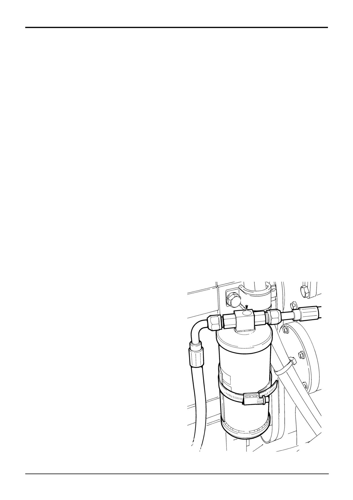
Checking Refrigerant Charge Level
The pressure in the system, i.e. the refrigerant charge level
Leak Testing
can be determined by checking the state of refrigerant at the
receiver drier sight glass.
Note: The refrigerant is heavier than air and will leak
downwards from the defective component. Check in still
If the level of charge is correct the sight glass will be clear. If
conditions but in a well ventilated area.
the charge is low bubbles will be seen. Bubbles may also be
an indication of inadequate cooling, due to a restriction of air
Hose or pipe connections are likely leakage points of any
flow around the condenser coil. Recharging of the system
refrigerant circuit.
should be carried out by an air conditioning engineer. Check
refrigerant charge level as follows:
To test for leaks in the high pressure side of the system i.e.
from the compressor output to the expansion valve, run the
1
Park the machine on firm, level ground. Lower the
air conditioning for a few minutes then switch off the engine
backhoe and loader to the ground.
and test for leakage using an electronic leak detector.
2
Remove the starter key.
To test for leakage in the low pressure side of the system,
switch off the air conditioning and leave for a few minutes
3
Remove the front grille.
before testing.
! WARNING
! WARNING
Leak testing in Air Conditioning systems should be
When the engine is turning, there are parts rotating in
carried out only in a well ventilated area.
the engine compartment.
BF 1-2
Before starting this job make sure that you have no
loose clothing (cuffs, ties etc) which could get caught in
rotating parts.
Tightening Leaking Hoses
When the engine is turning, keep clear of rotating parts.
2-3-3-10
! WARNING
4
Start the engine and run at idle. Switch air conditioning
The air conditioning system is a closed loop system and
ON to circulate refrigerant.
contains pressurised refrigerant. No part of the system
5
Check refrigerant charge level at sight glass A.
must be disconnected except by a qualified refrigeration
engineer.
4-3-4-1
The refrigerant hoses have crimped ferrule end fittings. The
hose connectors have an 'O' ring seal which compresses
A
when the connection is tight, creating an air tight seal.
Hoses are used to connect the inlets and outlets of the
compressor, condenser, receiver drier and expansion valve
(the evaporator coil is connected to the expansion valve
within the air conditioning unit using rigid pipes).
If leakage is detected from a hose connector, either by
means of an electronic leak detector or soapy water, tighten
the connector up and repeat the leakage test. If leakage is
still evident, it will be necessary to de-gas the system and
renew the connector 'O' ring seal.
The 'O' rings used on an R-134a refrigerant system are of an
HNBR compound and are colour coded green. These 'O'
rings must be used as some 'O' ring materials can become
porous to R-134a systems, resulting in leakage.
S190460
9803/3280
Issue 1
Section B
Body & Framework
Section B
20 - 2
Service Procedures
20 - 2
Air Conditioning
- Refrigerant Charging and Discharging
Note: The procedures for refrigerant charging and
discharging must only be carried out by qualified service
personel who have received specialist training on the air
conditioning system.
! WARNING
The air conditioning system is a closed loop system and
contains pressurised refrigerant. No part of the system
should be disconnected until the system has been
discharged by a refrigeration engineer or a suitable
trained person. You can be severely frostbitten or injured
by escaping refrigerant.
4-3-4-1/2
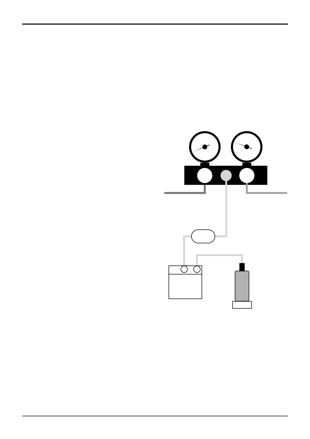
Refrigerant Recovery
The recovery process clears the system refrigerant proir to
servicing or for refrigerant renewal.
Lo
Hi
1
Ensure that the engine is OFF and the starter key
removed.
2
Connect the manifold to the system as shown, with the
To system Low
To system High
blue hose connected to the system low pressure port.
Pressure port.
Pressure port.
DO NOT connect the red hose. Make sure that both
Valve OPEN
Valve CLOSED
valves are closed.
3
Connect the yellow hose to the ‘Javac’ unit filter.
Filter
4
Connect the filter to the ‘Javac’ unit.
5
Connect the ‘Javac’ unit to an empty receiver bottle.
Weigh the bottle before and after filling to assess
system capacity.
IN
DIS
6
Switch on ‘Javac’ unit and open the low pressure
Refrigerant
manifold valve.
Cylinder
'Javac' Unit
7
The ‘Javac’ unit will automatically switch off when a
pressure balance exists between the system and the
receiver bottle. Switch off ‘Javac’at main switch, but
Scales
leave the system connected. Switch on after
10
minutes, the ‘Javac’ will restart if residual pressure
A396820
remains.
8
Close valves and remove equipment.
Notes:
DO NOT fill the receiver bottle to more than 80% by weight.
DO NOT re-use refrigerant unless you are aware of its purity.
If the high pressure warning light on the ‘Javac’ unit comes
on, throttle back the manifold low pressure valve to provide
a restriction.
The JCB recommended ‘Javac’ unit only recovers refrigerant
as a gas. Other units can recover refrigerant as a liquid
and/or gas. ALWAYS check manufacturers instructions
before using.
9803/3280
Issue 1
Section B
Body & Framework
Section B
20 - 3
Service Procedures
20 - 3
Air Conditioning
- Refrigerant Charging and Discharging
Note: The procedures for refrigerant charging and
discharging must only be carried out by qualified service
personel who have received specialist training on the air
conditioning system.
! WARNING
The air conditioning system is a closed loop system and
contains pressurised refrigerant. No part of the system
should be disconnected until the system has been
discharged by a refrigeration engineer or a suitable
trained person. You can be severely frostbitten or injured
by escaping refrigerant.
4-3-4-1/2
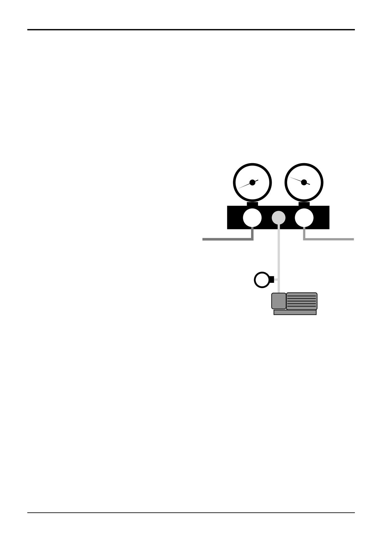
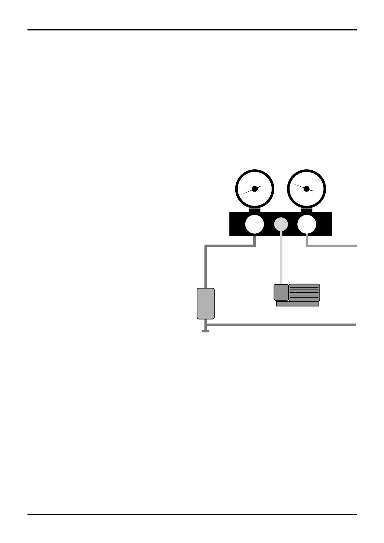
Evacuating (Vacuuming)
This procedure follows on from the ‘Recovery’ process and
is necessary to ensure proper refilling of the system with
refrigerant.
Lo
Hi
To avoid leakage in the vacuum system itself, DO NOT use
extensions to the yellow hose (use standard 2 metre length).
To system Low
To system High
1
Recover all refrigerant from the system as described in
Pressure port.
Pressure port.
Refrigerant Recovery.
Valve OPEN
Valve OPEN
2
Close all valves and connect the manifold as shown.
CPSVG100
Connect the blue hose to the system low pressure port
Vacuum guage
and the red hose to the high pressure port.
(If used)
3
Connect the yellow hose to the vacuum pump.
4
Open manifold valves.
Vacuum Pump
5
Switch on the vacuum pump until 740mm (29 in)
A396780
mercury vacuum reads on both gauges.
6
Maintain suction for approximately 30 minutes.
7
Close valves and remove equipment.
Notes:
If the vacuum falls rapidly the system is leaking. Check all
connections and reseal. If the point of leakage is not
obvious, recharge the system and test again. Refer to
Service Procedures, Air Conditioning - Leak Testing.
Achievable vacuum will vary with altitude. Maximum gauge
reading will be 25mm (1 in) less for every 305 metres ( 1000
feet) above sea level.
9803/3280
Issue 1
Section B
Body & Framework
Section B
20 - 4
Service Procedures
20 - 4
A396790
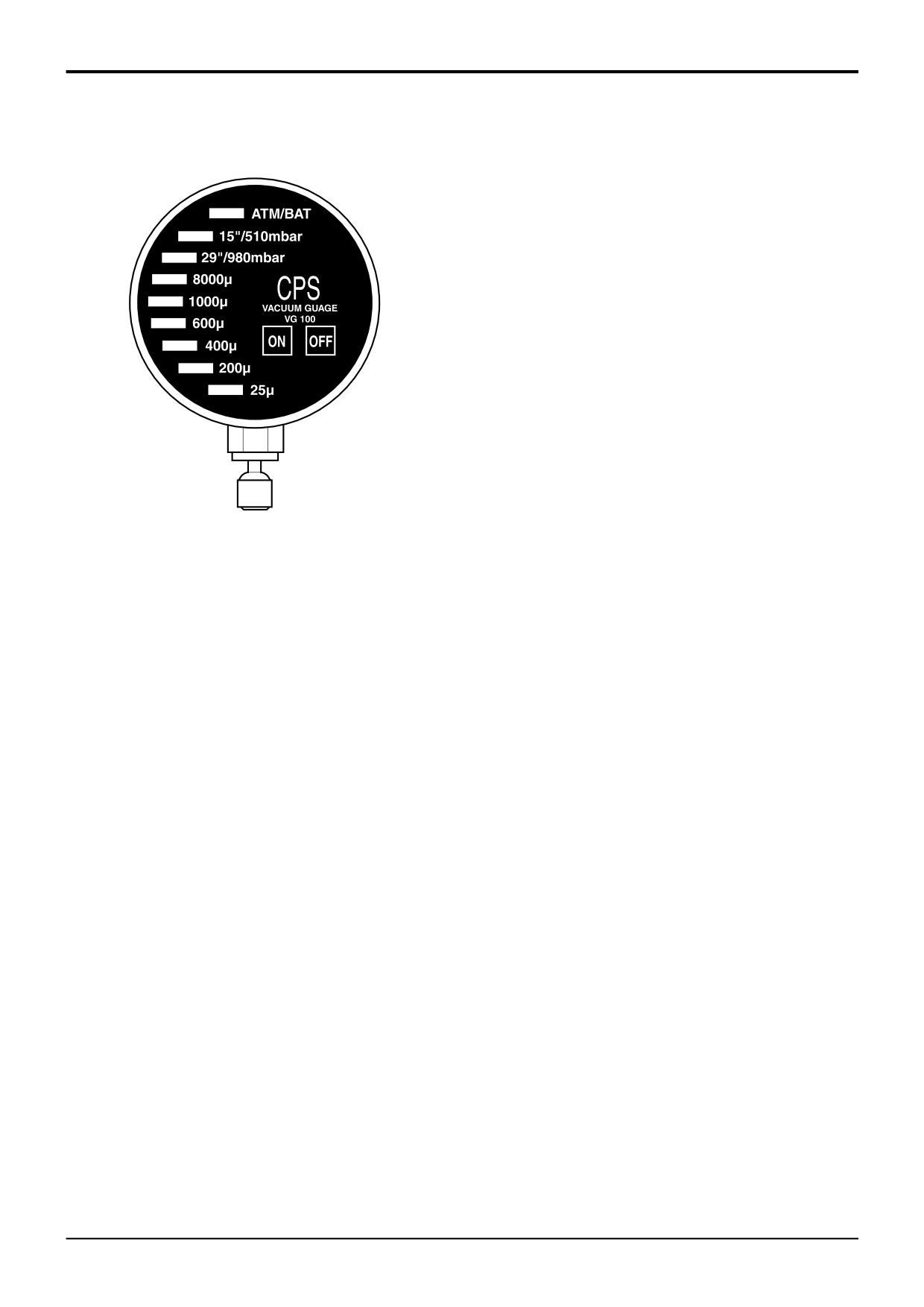
Electronic Vacuum Gauge
The CPS VG100 vacuum gauge is an electronic type using
LED’s to indicate various states of vacuum. It is used in
place of or to supplement the gauge on the vacuum pump.
Before connecting into the system switch on to check that
the first LED lights to show that the battery is in good
condition.
Note: The indicator lights show pressure in inches of
mercury (Hg) and vacuum in microns (0.001mm Hg).
ATM/BAT
Normal atmospheric pressure reading.
Battery condition.
15’’/510mbar
381mm (15 in)Hg. Partial vacuum -
Vacuum system is operating.
29’’/980mbar
736mm (29 in)Hg. No vacuum drawn -
Possible system leakage.
8000µ
8.0mm (0.31 in)Hg. Partial vacuum -
If the reading does not progress the
system may have a slow leak.
1000µ
1.0mm (0.039 in)Hg. Deeper vacuum.
600µ
0.6mm (0.023 in)Hg. Deep vacuum.
400µ
0.4mm (0.015 in)Hg. Deep vacuum.
200µ
0.2mm (0.0078 in)Hg. Deep vacuum.
25µ
0.025mm (0.00098 in)Hg. Pump Test.
Maximum sustainable vacuum.
9803/3280
Issue 1
Section B
Body & Framework
Section B
20 - 5
Service Procedures
20 - 5
Air Conditioning
- Refrigerant Charging and Discharging
Note: The procedures for refrigerant charging and
discharging must only be carried out by qualified service
personel who have received specialist training on the air
conditioning system.
! WARNING
The air conditioning system is a closed loop system and
contains pressurised refrigerant. No part of the system
should be disconnected until the system has been
discharged by a refrigeration engineer or a suitable
trained person. You can be severely frostbitten or injured
by escaping refrigerant.
4-3-4-1/2
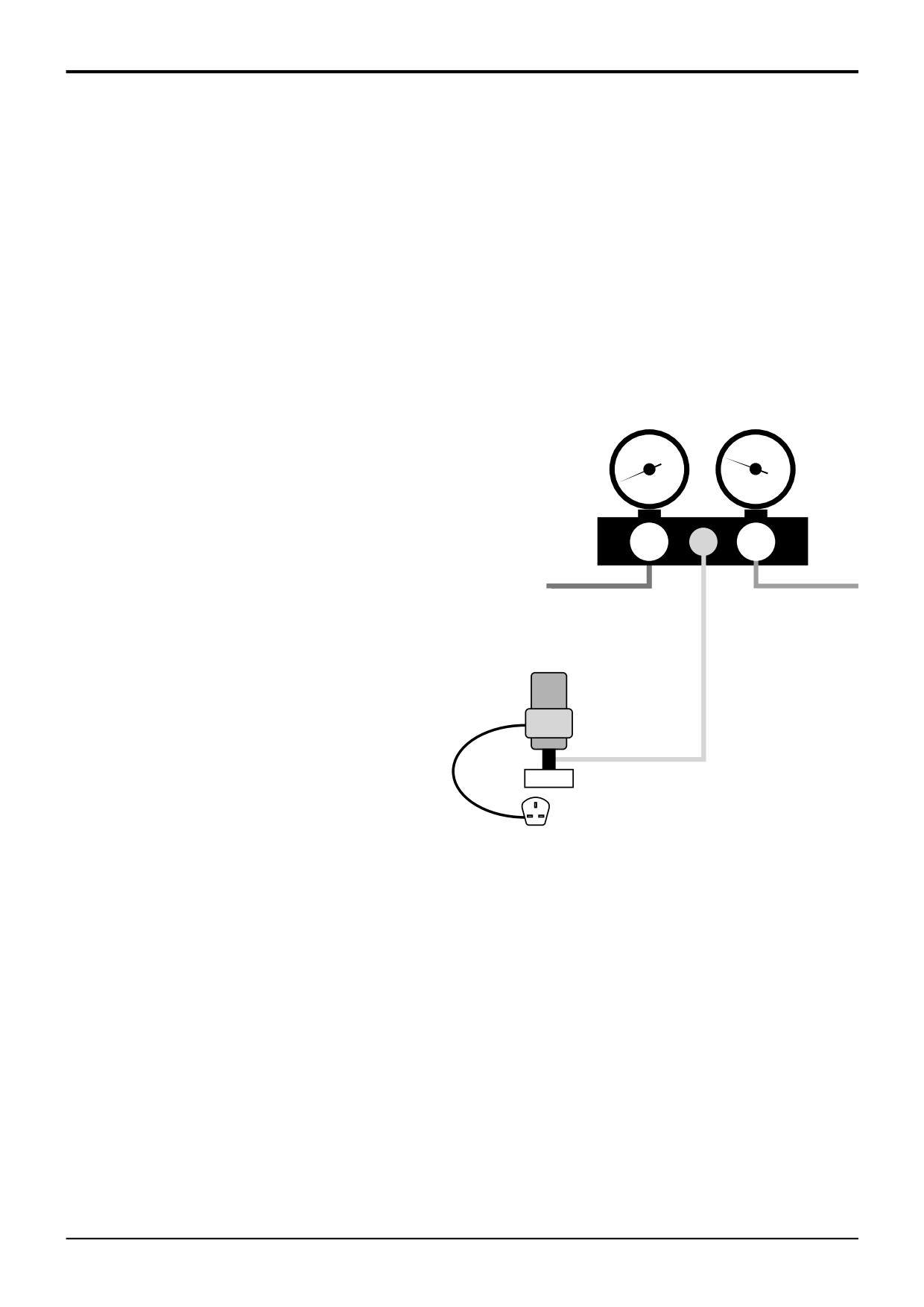
Relubricating
Pre-lubrication is essential after recovering system
refrigerant, vacuuming and component flushing.
The system should be evacuated to a vacuum of 740mm (29
Lo
Hi
in) of mercury before re-lubricating.
1
Ensure that the engine is OFF and the starter key is
removed.
To system Low
To system High
Pressure port.
Pressure port.
2
Close all valves and connect the manifold as shown,
Valve OPEN
Valve OPEN
with the blue hose connected to the oil injector and the
red hose to the system high pressure port.
3
Connect the yellow hose to the vacuum pump.
Oil Injector
4
Connect the other end of the oil injector to the system
Vacuum Pump
low pressure point.
5
Switch on the vacuum pump and open the high
To system Low
pressure side valve.
Oil injector valve -
Pressure port.
Open when full
6
Unscrew the oil injector cap and add the specified
vacuum is obtained.
quantity of refrigerant oil.
A396800
7
When 740mm (29 in) mercury shows on the vacuum
gauge, open the oil injector valve to allow the oil into
the system.
8
If more oil is needed repeat the above procedure. The
quantity of oil should be the same as that taken out
during the ‘Recovery’ procedure.
Notes:
Use only PAG oil in R-134a systems.
9803/3280
Issue 1
Section B
Body & Framework
Section B
20 - 6
Service Procedures
20 - 6
Air Conditioning
- Refrigerant Charging and Discharging
Note: The procedures for refrigerant charging and
discharging must only be carried out by qualified service
personel who have received specialist training on the air
conditioning system.
! WARNING
The air conditioning system is a closed loop system and
contains pressurised refrigerant. No part of the system
should be disconnected until the system has been
discharged by a refrigeration engineer or a suitable
trained person. You can be severely frostbitten or injured
by escaping refrigerant.
4-3-4-1/2
Charging
This procedure is industry recommended practice for
refilling air conditioning systems with refrigerant.
Evacuate the system beforehand to 740mm (29 in) of
Lo
Hi
mercury.
1
Close all valves and connect the manifold as shown.
To system Low
To system High
Connect the blue hose to system low pressure and the
Pressure port.
Pressure port.
red hose to system high pressure. Connect the yellow
Valve CLOSED
Valve OPEN
hose to the refrigerant cylinder.
2
Invert single valve cylinder on the scales and zero the
Refrigerant
scale reading (see Notes: for twin valve cylinders).
Cylinder
Thermal Blanket
3
Slowly open the high pressure valve and allow the
vacuum to draw-in refrigerant to the specified weight
for the system. Refer to Technical Data.
Scales
4
Close all valves and remove the equipment.
A396810
Notes:
Add refrigerant as a LIQUID, not as a gas. Some refrigerant
cylinders have separate valves for gas and liquid. Be sure to
connect to the liquid port when following the above
procedure.
Refrigerant can be used either in gas or liquid form. If
recharging with gas follow the manufacturers instructions
and recharge only via the low pressure port. DO NOT use
liquid refrigerant at the low pressure port.
Add refrigerant until the scales indicate the specified weight
for the system or the weight obtained when the system
refrigerant was previously recovered.
To speed up the process a thermostatically controlled
thermal blanket can be used around the replenishing
cylinder.
9803/3280
Issue 1
Section B
Body & Framework
Section B
20 - 7
Service Procedures
20 - 7
Air Conditioning
Binary Pressure Switch Testing
The binary pressure switch assembly comprises a low
pressure switch designed to open at 1.96 bar (28.4 lbf/in2)
and a high pressure switch designed to open at
27.5 bar (400 lbf/in2)
When the refrigerant pressure is within the 1.96 and 27.5 bar
limits the switches will be closed and providing the freeze
protection thermostat and ON/OFF switches are closed, a
current will be supplied to the field coil of the clutch.
Through electro- magnetic action the field coil clutch will be
pulled towards the compressor's clutch and the refrigeration
cycle will commence.
If the fault finding table indicates that the pressure switch
assembly is defective the fault may be electrical or due to
incorrect system pressure.
Refer to Checking Refrigerant Charge Level. If the
refrigerant charge level is OK use the following electrical test
procedures.
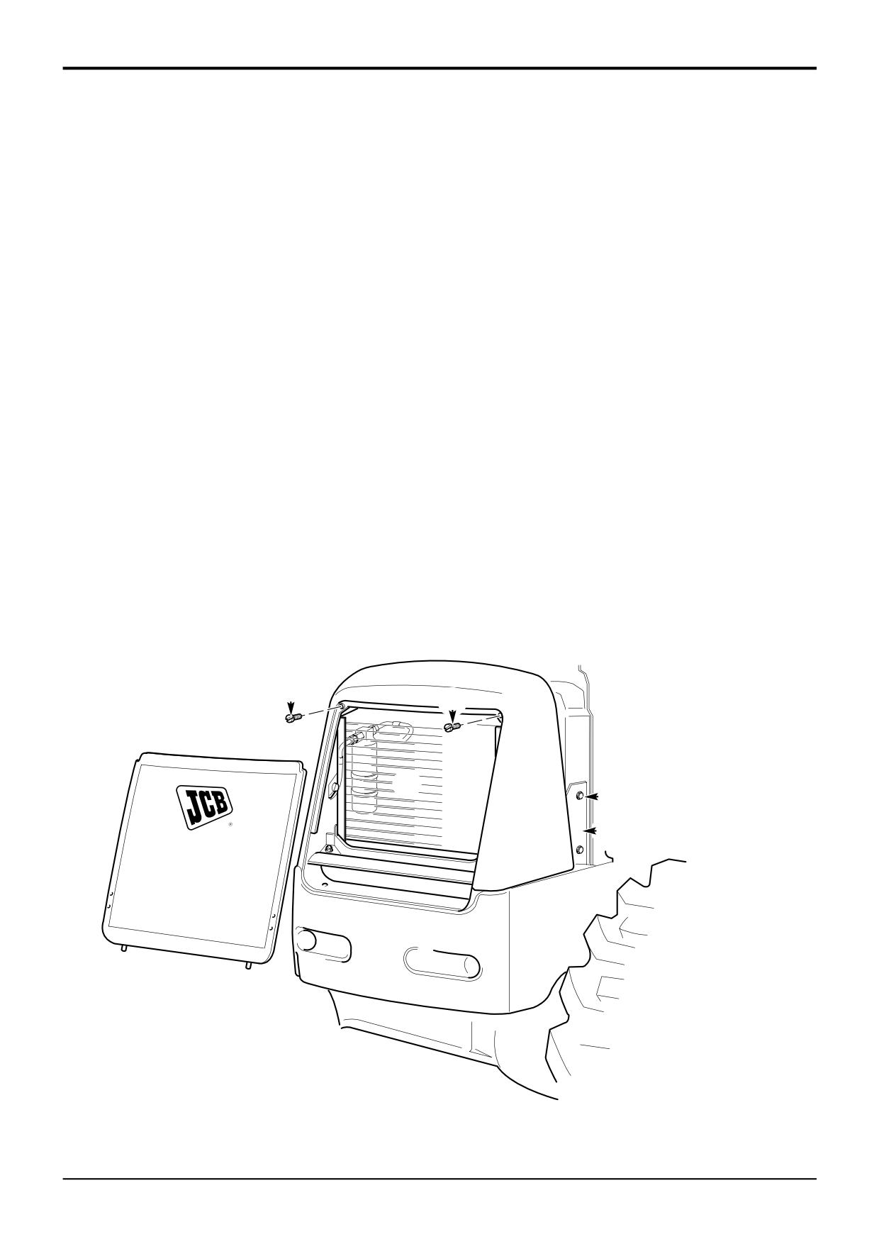
1
Switch the engine off so that the air conditioning
system cannot operate.
2
Disconnect the binary pressure switch harness from the
side console harness and connect an external 12V
power supply between the pressure switch harness
connector and chassis. If both pressure switches are
working correctly, and the system is at the correct
charge level, the compressor clutch will operate.
If the compressor clutch does not operate with the
external power supply, one of the pressure switches in
the assembly is faulty or the level of refrigerant charge
is insufficient to close the low pressure switch.
3
Replace the pressure switch assembly. Refer to Binary
Pressure Switch - Removal and Replacement. If the
clutch still fails to operate check all electrical
connections.
9803/3280
Issue 1
Section B
Body & Framework
Section B
20 - 8
Service Procedures
20 - 8
Air Conditioning
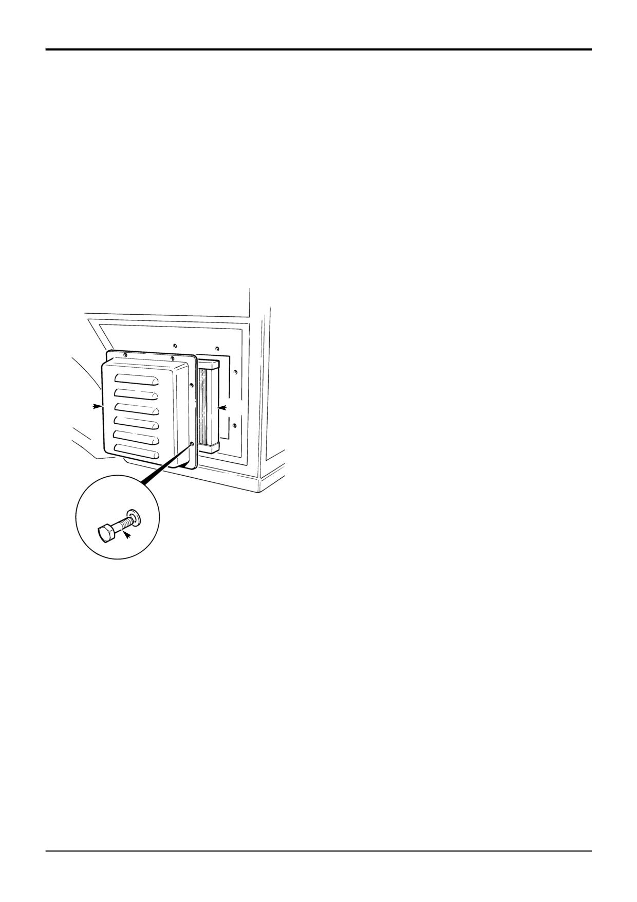
Condenser Matrix
2
Remove the starter key.
It is likely that over a period of time, because of the
3
Remove the front grille.
machine's working environment, the airflow around the
condenser matrix will become restricted due to a build up of
4
Remove both side panels.
airborne particles.
5
Support the condenser 1.
If the build up of particles is severe, heat dissipation from
the refrigerant to the air will be significantly reduced,
6
Undo the nuts and bolts 2 at the three mounting
resulting in poor air conditioning performance.
brackets 3.
In extreme cases, over pressurisation of the system occurs,
7
Remove the screws 4 fixing the condenser to the
causing the high pressure cut out switch to operate and
mounting brackets. Remove the brackets 3 to enable
switch off the system.
the condenser to be moved away from the radiator.
This can be done without removing the hoses i.e. with
High pressure cut out can also be caused by an internal
the system fully charged.
blockage of the condenser matrix.
8
With the condenser fully supported, use compressed
Condenser Matrix Cleaning
air or low pressure water to backflow through the
matrix fins. Take care not to damage the fins.
Take care not to damage the condenser fins or tubes.
Damaged fins must be straightened out to ensure a good
9
Refit the condenser matrix by reversing the removal
airflow through the matrix.
procedure. Refit both side panels and bonnet.
1
Park the machine on firm level ground. Raise and block
10
Run the air conditioning and check cooling
the loader arms. Lower the backhoe to the ground and
performance.
stop the engine.
4
4
1
2
3
A401500
9803/3280
Issue 1
Section B
Body & Framework
Section B
20 - 9
Service Procedures
20 - 9
Air Conditioning
Filters - Changing and Cleaning
Air Intake Filter
1
Stop the engine and remove the starter key.
2
Remove Screws D, air intake cover E and filter F.
Clean filter element using compressed air. Refit filter
into the cover and refit.
E
F
D
S190470
9803/3280
Issue 1
Section B
Body & Framework
Section B
20 - 10
Service Procedures
20 - 10
Air Conditioning
Compressor Drive Belt - Adjusting
1
Park the machine on firm level ground. Raise and block
the loader arms. Lower the backhoe to the ground and
stop the engine.
X
2
Remove the starter key.
C
B
! WARNING
Make sure the engine cannot be started. Disconnect the
battery before doing this job.
2-3-3-5
3
Raise the Bonnet
4
Remove both Side Panels
5
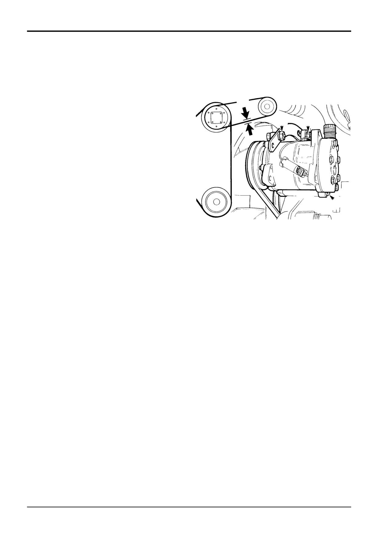
Loosen pivot fastening bolt A. Loosen adjustment link
A
fastening bolts B and C.
6
Position the compressor so that there is approximately
S209393
10 mm (3/8 in) slack at point X midway along the belt.
7
Tighten bolts A, B and C. Make sure that bolt A is the
last to be tightened.
Note: If a new belt is fitted, check the belt tension after the
first 20 hours of operation.
9803/3280
Issue 1
Section B
Body & Framework
Section B
21 - 1
Service Procedures
21 - 1
Glazing
The glass panes on the cab are all direct glazed.
Direct Glazing
The following procedures explain how to correctly remove
Removing the Broken Glass and Old Sealant
and install panes of glass that are directly bonded to the cab
frame apertures. When carrying out the procedures, relevant
Several special tools are required to successfully complete
safety precautions must be taken:
the removal and replacement procedures. Reference is
made to the tools in the text. The majority of these tools can
1
Always wear safety glasses during both removal and
be obtained locally and the remainder from JCB Service
replacement.
(see Service Tools).
2
Use protective gloves - heavy duty leather gauntlet type
The work must only be carried out in a dry, frost free
gloves when cutting out the broken glass; 'non-slip'
environment. A protective canopy may be required or the
type gloves when handling/moving panes of glass;
machine/frame must be moved to a sheltered area. In damp
surgical type gloves when using the polyurethane
or wet conditions, hinged doors and window frames can be
adhesives.
removed from the machine and taken to a more suitable
(dry) environment.
3
Wear protective overalls.
Glass should not be replaced at temperatures below 5°C
4
DO NOT smoke - the activators and primers used in the
(41°F).
procedures are highly flammable.
5
Do not attempt to handle or move panes of glass
Note: The front screen glass is laminated, the other glass is
unless you are using glass lifters (see Service Tools).
toughened. If a laminated pane breaks it will stay in one
piece even though the glass is cracked. A toughened pane
will shatter and fall apart. The method of removal of the
glass depends upon which type it is. See WARNING below.
! WARNING
Always wear safety glasses when removing or installing
screen glass. Never use a power operated knife when
removing the sealant around a toughened glass screen.
The action of the knife could cause particles of glass to
be thrown with sufficient force to cause serious injury,
even when safety glasses are being worn. Use only hand
operated tools when working with toughened glass.
BF 2-3/1
9803/3280
Issue 1
Section B
Body & Framework
Section B
21 - 2
Service Procedures
21 - 2
Direct Glazing (cont'd)
Removing the Broken Glass and Old Sealant (cont'd)
1
Position the machine on level ground and apply the
parking brake. Stop the engine. Put protective covers
over the cab seat and control pedestals.
2
a Laminated glass - leave installed until the old
sealant has been cut away, after which it will be
possible to lift the broken screen away from its
A
frame housing in one piece.
b Toughened glass
- remove as much of the
shattered glass as possible prior to cutting out the
old sealant.
3
Cut out the old sealant, leaving approximately 1 to 2
mm on the cab frame. There are several tools and
S186380
techniques for doing this:
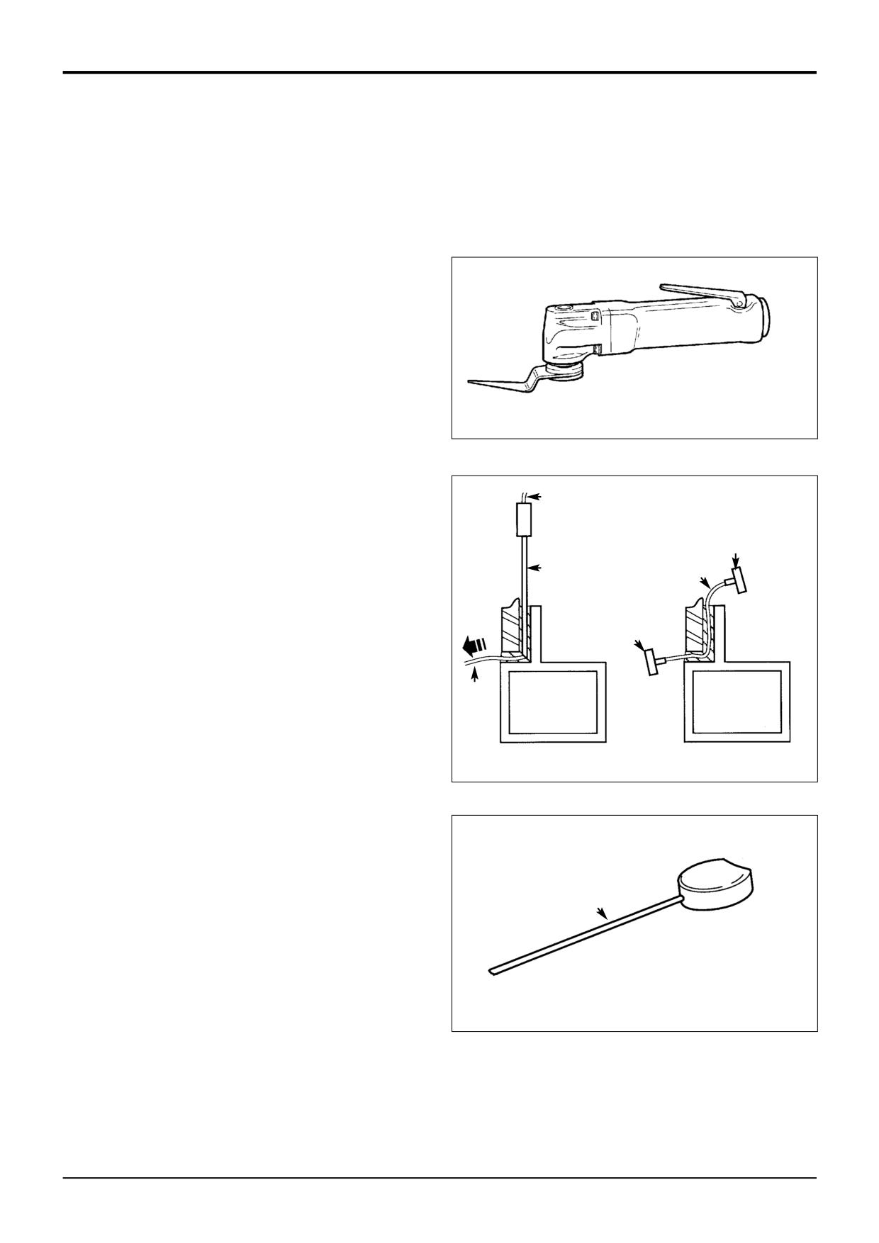
a Pneumatic Knife A provides one of the easiest
methods of removing the sealant around laminated
glass. The tool, powered by compressed air,
B D
should be sourced locally.
Note: This tool must not be used on toughened glass (see
E
WARNING on previous page).
C
D
(i)
Press the handle to start the knife blade oscillating.
(ii)
Insert the knife blade into the sealant.
E
(ii)
Slowly move the knife along the sealant with the
blade positioned as close to the glass as possible.
Do not allow the knife blade to overheat or the
D
sealant will melt.
b Braided Cutting Wire and Handles B. This method
uses a 3-core wire, a wire starter tube and two
S189870
handles (see Service Tools).
(i)
Insert the steel tube C into the old sealant on the
inside of the glass.
(ii)
Insert the braided cutting wire D down the centre of
the steel tube. If necessary, from the outside, cut
out local sealant at the point of the tube to gain
access to the wire.
C
(iii) Using suitable pliers, pull the cutting wire through
the sealant to the outer side of the glass.
(iv) Secure each end of the braided cutting wire in the
special handles E.
S189880
(v) Move the cutting wire backwards and forwards in a
sawing motion and at the same time gently push or
pull the wire to cut through the old sealant.
9803/3280
Issue 1
Section B
Body & Framework
Section B
21 - 3
Service Procedures
21 - 3
Direct Glazing (cont'd)
Removing the Broken Glass and Old Sealant (cont'd)
F
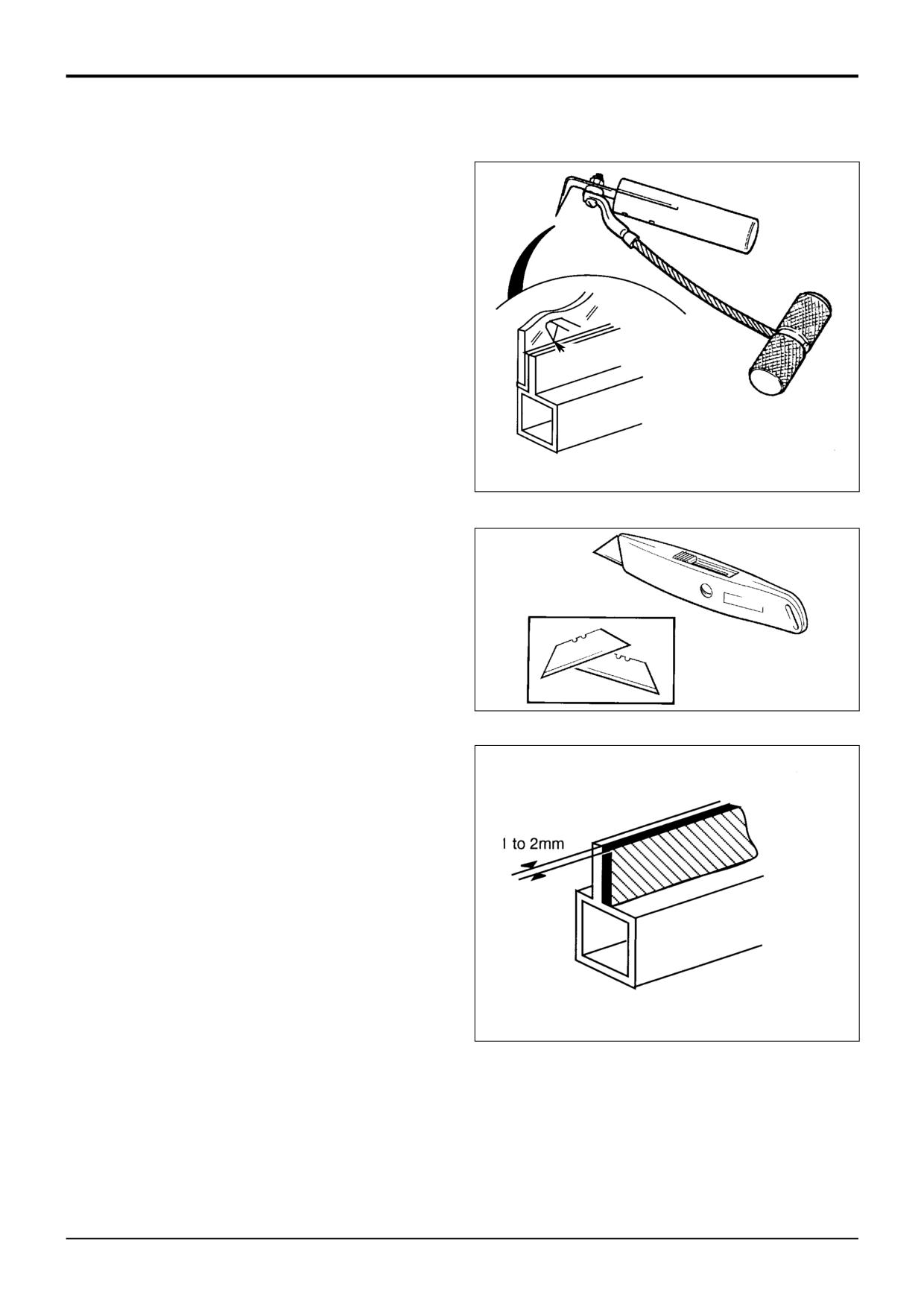
c Cut-out Knife F. The cut-out knife can be used as a
left handed or right handed tool. For the knife and its
replaceable blades, refer to Service Tools.
(i)
Insert the knife blade into the sealant.
(ii)
Make sure that the blade of the knife is against
the glass as shown at G.
(iii)
Use the 'pull-handle' to pull the knife along and
G
cut out the old sealant.
d Craft Knife H. The blades are replaceable.
(i)
Insert the knife blade into the sealant.
S189890
(ii)
Pull the knife along and cut out the old sealant.
Note: There are other tools available to cut out the old
sealant. For example, there is a long handle type craft knife
to give extended reach. Refer to Service Tools, for details of
H
this and any other tools.
4
a Laminated glass - lift out the broken pane using
glass lifters (see Service Tools).
b Toughened glass - remove the cut off sealant and all
remaining particles of shattered glass.
S186370
5
If necessary, trim off the remaining old sealant to leave
approximately 1 to 2 mm on the upright face of the cab
frame aperture, as shown at J.
6
Apply a coat of 'Black Primer 206J' to the paintwork if:
J
a Paintwork was damaged or scratched during the
glass/sealant removal procedures.
b The old sealant was inadvertently cut back to the
cab frame during the glass/sealant removal
procedures.
Preparing the Cab Frame Aperture
1
If damp or wet, dry the aperture area using a hot air gun
(sourced locally).
2
Use 'Active Wipe 205' to thoroughly clean and 'prime'
the trimmed sealant. Use a lint free cloth to apply the
S189900
'Active Wipe 205', allow 5 minutes flash off (drying)
time.
Note: Do not use any other type of cleaning fluids, otherwise
they may be absorbed into the old sealant and ultimately
prevent the new glass from bonding.
9803/3280
Issue 2*
Section B
Body & Framework
Section B
21 - 4
Service Procedures
21 - 4
Direct Glazing (cont'd)
K
Preparing the New Glass
! CAUTION
M
The laminated front screen must be handled with extra
care to prevent breakage. Wherever possible, store and
handle it in a vertical attitude. When placing or lifting the
screen in a horizontal attitude it must be supported over
its whole area, not just at the edges.
BF 1-8
1
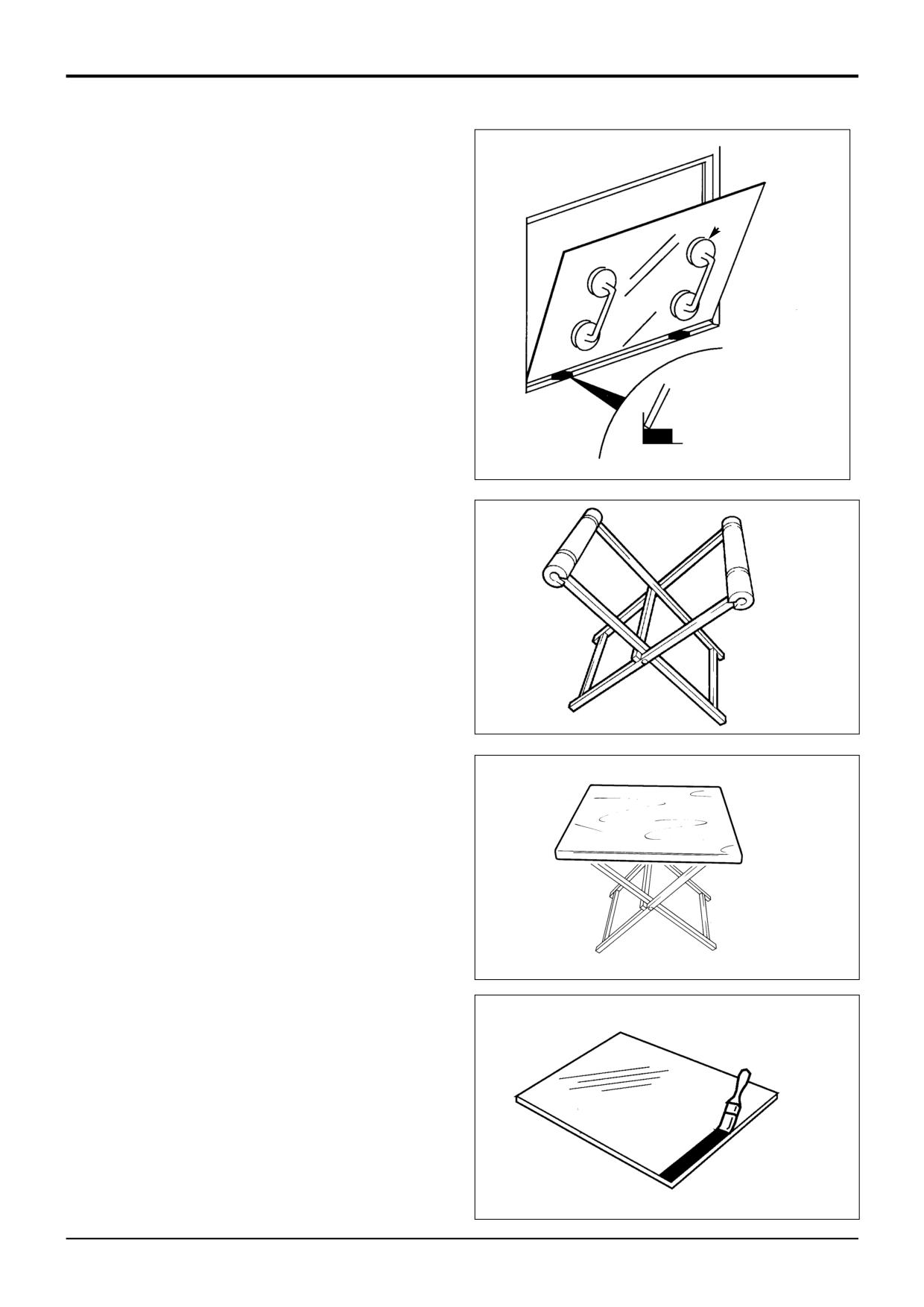
Make sure that the new glass correctly fits the frame
aperture K.
a Put two spacer blocks L onto the bottom part of the
frame aperture.
L
b Install the new glass on the spacer blocks - ALWAYS
S189910
USE GLASS LIFTERS M (see Service Tools). Check
that there is an equal sized gap all round the edge of
the glass.
Note: The spacer blocks are rectangular in section to give
N
two common gap widths. If necessary they can be trimmed
to a smaller size to give an equal sized gap around the glass.
IMPORTANT: The glass edges MUST NOT touch the frame,
otherwise movement of the frame will chip and eventually
break the newly installed glass.
2
After checking for size, remove the new glass and place
it on a purpose made glass stand N (see Service
Tools).
S186280
Small panes of glass will need locating on a 600 x 700 mm x
15 to 19 mm thick plywood board P (sourced locally to fit
the glass stand N). It is recommended that an access hole is
cut in the board to accommodate the glass lifter, making it
P
easier and safer to handle small panes of glass. The board
should be covered with felt or carpet to give an anti-scratch
surface. Resting the glass on four spacer blocks will ensure
clearance of the cartridge nozzle tip during application of the
polyurethane sealant.
3
Make sure the glass is positioned on the stand the
correct way up (i.e. with the black ceramic ink band
upwards) ready for application of primer etc.
S186291
4
a Use 'Active Wipe 205' to thoroughly clean and
'prime' the black ceramic ink band printed on the
glass (see Note 1). Use a lint free cloth to apply the
'Active Wipe 205', allow 5 minutes flash off (drying)
R
time.
Note 1: Do not touch the glass after cleaning with the
'Active Wipe 205'.
b If the glass does not have a black ceramic ink band,
paint a band on the glass using 'Black Primer 206J'.
The band should be approximately 25mm (1in) wide,
and the edge should be a neat straight line as shown
at R.
S189920
9803/3280
Issue 1
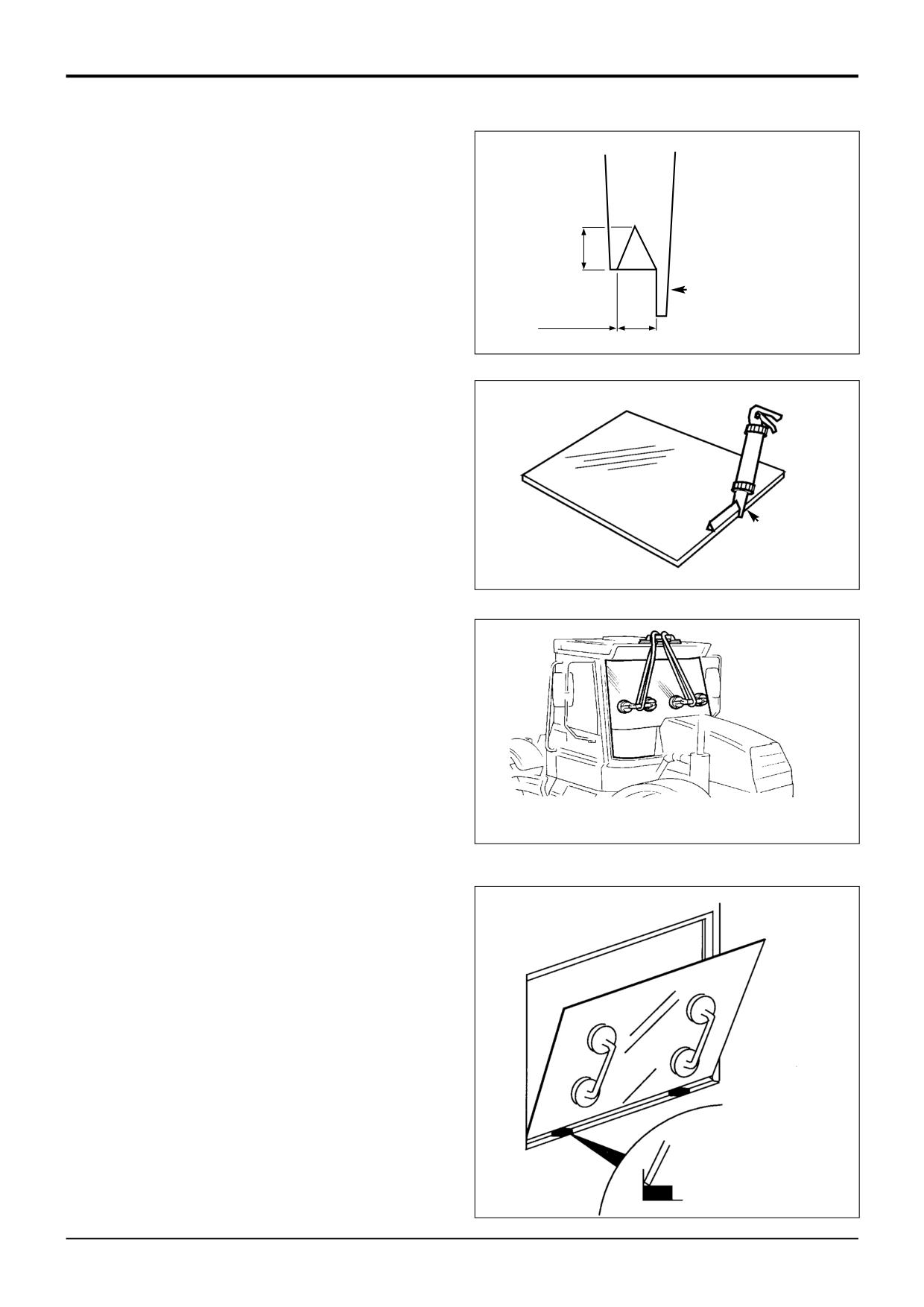
Section B
Body & Framework
Section B
21 - 5
Service Procedures
21 - 5
Direct Glazing (cont'd)
S
Preparing the New Glass (cont'd)
5
Install the Ultra Fast Adhesive cartridge (see Sealing
and Retaining Compounds and Note 2 below) into a
suitable applicator gun:
10-15mm
a Remove the aluminium disc cover from the base of
the cartridge and discard the 'dessicant capsule'.
T
8-10mm
b Make sure that the rolled edge of the cartridge is not
A186410
damaged - if necessary, the edges should be
pressed flat, otherwise it will be difficult to remove
the cartridge from the applicator gun.
c Pierce the front 'nozzle' end of the cartridge to its
maximum diameter.
d Fit the pre-cut nozzle shown at S.
e Install the cartridge in the applicator gun.
Note 2: Cold material will be very difficult to extrude. The
T
cartridges must be pre-heated in a special oven (see
Service Tools) for 1 hour to a temperature of 80°C (176°F).
S189930
Pre-heating the cartridges makes the adhesive more
workable and also brings the 'curing' time down to 30
minutes.
6
Apply the pre-heated adhesive to the glass (do not start
W
in a corner). Keep the nozzle guide T against the edge
of the glass and make sure that the adhesive forms a
continuous 'pyramid' shape.
Note 3: Once the pre-heated adhesive has been applied to
the glass, install the glass in the aperture as soon as
possible. After approximately 10 minutes the sealant will
form a 'skin', this will prevent the glass from bonding.
7
After applying the adhesive, leave a small amount of
S186440
Typical m/c installation
sealant protruding from the nozzle. This will prevent any
adhesive left in the cartridge from 'curing'.
Installing the New Glass
1
Make sure the two spacer blocks are in position (see
X
step 1 of Preparing the New Glass).
2
Install the glass in the frame aperture:
a ALWAYS use the special lifting tools when moving
the glass. Use a lifting strap to hold large panes of
glass in position as shown W.
b Sit the bottom edge of the glass on the spacer
blocks as shown X.
c Make sure that the glass is correctly positioned, then
gently press around the edges of the glass and
ensure full adhesive contact is achieved. Do not
press too hard or too much adhesive will squeeze
out.
S189910
9803/3280
Issue 1
Section B
Body & Framework
Section B
21 - 6
Service Procedures
21 - 6
Direct Glazing (cont'd)
Installing the New Glass (cont'd)
3
Make the inside seal smooth:
a Wearing surgical gloves, dip your finger in a soapy
water solution.
b Use your finger to make the inside seal smooth.
4
All exposed edges must be sealed using Black
Polyurethane Sealant (see Sealing and Retaining
Compounds).
5
Clean the glass after installation:
IMPORTANT: Use extreme caution when wiping the inside
of the new glass - pushing too hard on the inside of the
glass will affect the integrity of the bonded seal.
a Small amounts of sealant can be cleaned from the
glass using the 'Active Wipe 205'.
b Large amounts of excess sealant should be left to
'cure' (see Note 4) and then cut off with a sharp
knife.
Note 4: On completion of the glass replacement procedures,
the sealant 'curing' time is 30 minutes. This means that the
machine can be driven and used after 30 minutes, but it
MUST NOT be used during the curing period of 30 minutes.
c Clean the glass using a purpose made glass
cleaner.
6
On completion of the glass installation procedures tidy
the work area:
a Remove ALL broken glass from the cab area.
b Remove the protective covers from the cab seat and
control pedestals.
c Renew all 'warning' and 'information' decals so that
the new installation conforms with the original cab
installation.
9803/3280
Issue 1
Section B
Body & Framework
Section B
22 - 1
Service Procedures
22 - 1
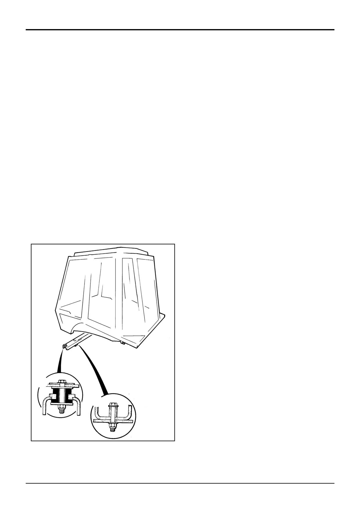
Cab ROPS/FOPS Structure - Checks
! WARNING
The machine is fitted with a Roll Over Protection
Structure (ROPS) and a Falling Objects Protection
Structure (FOPS). You could be killed or seriously injured
if you operate the machine with a damaged or missing
ROPS/FOPS. If the ROPS/FOPS has been in an accident,
do not use the machine until the structure has been
renewed. Modifications and repairs that are not
approved by the manufacturer may be dangerous and
will invalidate the ROPS/FOPS certification.
INT-2-1-9/3
Failure to take these precautions could result in death or
injury to the operator.
Check the structure for damage. Check that the mounting
bolts are installed and undamaged. Check the bolt torques.
Tighten them to the correct torque if necessary.
Torque Settings
Bolts A 205 Nm (150 lbf ft)
Bolts B 476 Nm (352 lbf ft)
A
B
S260180
9803/3280
Issue 1
Section B
Body & Framework
Section B
23 - 1
Service Procedures
23 - 1
Engine Panels
- Removing and Fitting
Instructions for removing and fitting the engine panels are
described in the routine maintenance section, refer to
Section 3 Routine Maintenance - Engine Panels.
9803/3280
Issue 1
Section B
Body & Framework
Section B
24 - 1
Service Procedures
24 - 1
Stabiliser Leg
Wear Pad Adjustment
Instructions for adjusting the wear pads are described in the
maintenance section, refer to Section 3 Stabiliser Legs -
Wear Pad Adjustment.
9803/3280
Issue 1
Section B
Body and Framework
Section B
25 - 1
Service Procedures
25 - 1
Extending Dipper
- Wear Pad Adjustment
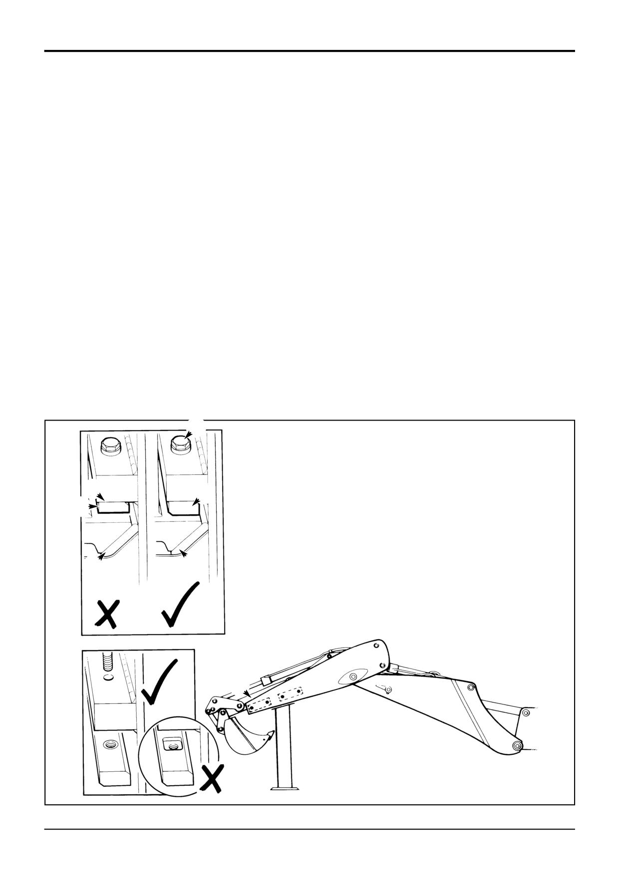
The Extradig dipper wear pads are bolt-on replaceable
Inspecting the Top Wear Pads
items. They support and guide the inner dipper section
during extension and retraction. The following procedures
1
Park the machine on level ground. Engage the parking
explain how to inspect, and where applicable, adjust the
brake and put the transmission in neutral.
pads.
2
Position the boom and dipper as shown at C. Retract
There is a front and rear set of pads, each set comprises top
the Extradig dipper D. Make sure that the bucket is
wear pads A and bottom wear pads B.
clear of the ground and the dipper is supported.
The top wear pads A are not adjustable and must be
3
Stop the engine and remove the starter key.
replaced with new pads once they have worn to their limit.
See Inspecting the Top Wear Pads.
Renew the pads when, or before they are worn down to the
depth of the recess/chamfer as shown at E. If the pads are
The bottom wear pads B are adjustable and take up the
worn near to their limit then inspect them more frequently
wear on both the top and bottom pads. They must also be
than recommended in the Service Schedules. To avoid
replaced with new pads once they have worn to their limit.
damage to the dipper or wear pad make sure the pads are
See Adjusting the Bottom Wear Pads.
fitted the correct way round as shown at J.
New wear pads A and B must be replaced as a set and
Torque Settings
fitted by a qualified service engineer.
Item
Nm
kgf m
lbf ft
F
56
5.7
4
F
A
A
E
B
B
D
J
C
S312991
9803/3280
Issue 1
Section B
Body and Framework
Section B
25 - 2
Service Procedures
25 - 2
Extending Dipper
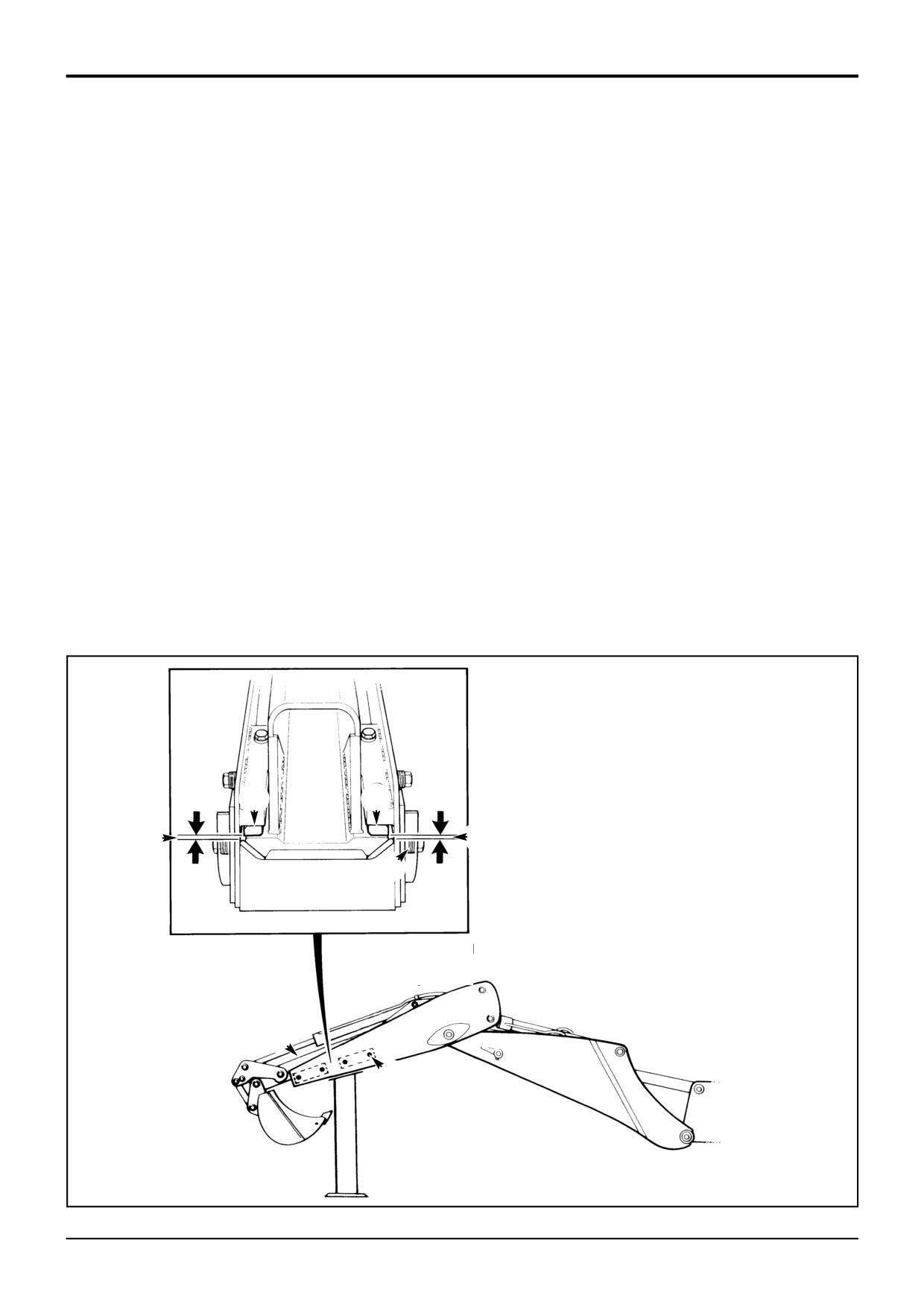
If the gap is greater than 1/16 in (1.5 mm) then adjust as
follows:
- Wear Pad Adjustment (Cont’d)
a Remove one adjusting bolt H and discard one
Adjusting the Bottom Wear Pads
washer J.
1
Park the machine on level ground. Engage the parking
b Refit and tighten bolt H.
brake and put the transmission in neutral.
c Repeat the procedure for the remaining 3 adjusting
2
Support the boom and dipper as shown at C.
bolts H on the same side of the dipper.
3
Stop the engine.
d Visually re-check the gap is no greater than 1.5 mm
(1/16 in) as shown at G, if necessary repeat steps a
4
Clean the sliding faces of the inner dipper with a
to c for the other 4 bolts H on the opposite side of
suitable solvent.
the dipper.
5
Start the engine. Retract the Extradig dipper D. Make
e Make sure that the inner dipper seats central to the
sure that the bucket is clear of the ground and the
sides of the outer dipper.
dipper is supported.
Note: Remember to alternate sides each time an adjustment
6
Stop the engine.
is made.
7
With grease, mud etc. removed from the sliding faces
Note: When all the adjusting washers J have been removed
visually check the gap between inner dipper and top
and the clearance is greater than 1.5 mm (1/16 in), then wear
wear pad A, as shown at G. The gap should be no
pads A and B must be replaced as a set and fitted by a
greater than 1.5 mm (1/16 in).
qualified service engineer.
When the adjustments have been completed, apply Waxoyl
to the runners of the inner dipper.
A
A
G
G
J
D
H
C
S148121
9803/3280
Issue 1
Section B
Body & Framework
Section B
26 - 1
Service Procedures
26 - 1
Sideshift
- Hydraclamp Clearance Setting
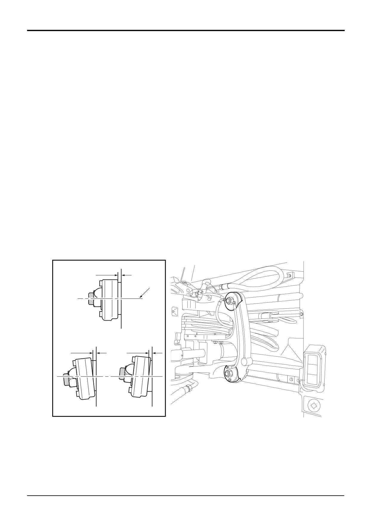
If the kingpost clearance D is not set correctly leaks may
occur or the seal could become dislodged, use the
procedure below to set the clearance.
1
Park the machine on firm level ground, engage the
parking brake and set the transmission to neutral.
Lower the loader arms to the ground.
2
Select the carriage clamps to lock.
3
Measure all four clamps clearance, all measurements
should be taken on the centre line A to allow for
twisting of the clamp pot as shown at B and C:
Manual
3 - 5 mm (0.11 - 0.19 in)
Power Sideshift
3 - 5 mm (0.11 - 0.19 in)
4
Release the clamps and tighten/loosen nut 1 as
required, recheck measurement. When correct bend
tab to lock nut.
D
A
D
D
B
C
338630
9803/3280
Issue 1
Section B
Body & Framework
Section B
26 - 2
Service Procedures
26 - 2
Power Sideshift - Wear Pad Renewal
Inspection (1000 hours)
Assembly
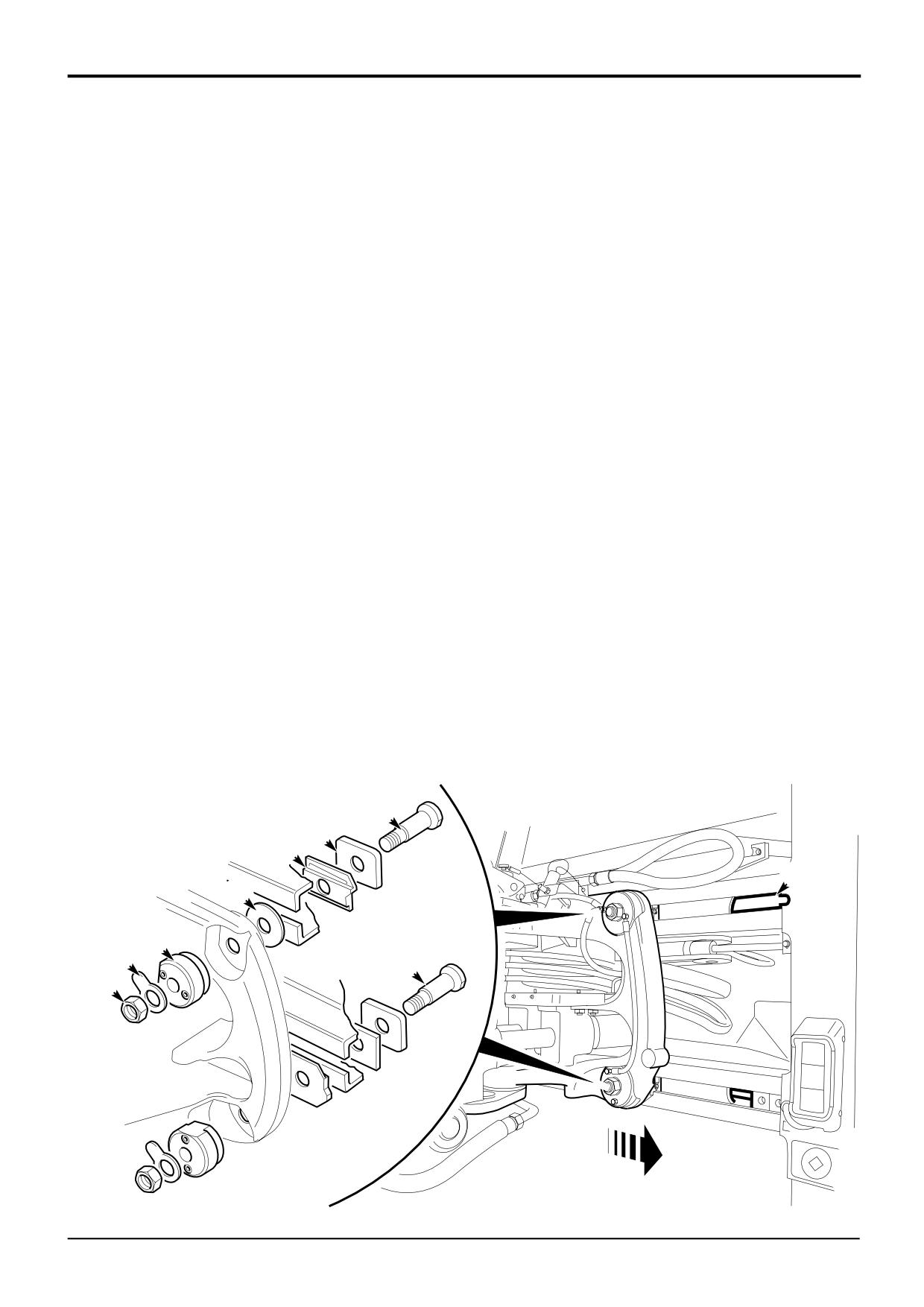
When the wear pads are worn to 6 mm (0.23 in) or below
9
Fit wear pad H, plate J and bolt D.
they should be replaced.
10
Fit new lock tab B and fit nut C.
It is permissible to rotate the top wear pads 180° to prolong
service life, provided the contact surface is more than 6 mm
11
Set the hydraclamp clearance as described in Sideshift
(0.23 in) thick.
- Hydraclamp Clearance Setting.
Note: If rotating the wear pad the grease nipples will have to
12
Repeat procedure steps 5 to 11 for the bottom clamp.
be swopped over.
The only difference on the bottom clamps is the wear
pad is on the opposite side of the rail from the top
Dismantling
clamp so bolt K need not be completely removed.
1
Park the machine on firm level ground, engage the
Note: If the wear pad is trapped between the rail and
parking brake and set the transmission to neutral.
carriage, lower the bucket to relieve the load on the wear
Lower the loader arms to the ground.
pad.
2
Set the carriage fully to end of travel A, shown in centre
13
Lift the bucket and set the carriage to the opposite end
position for clarity.
of the travel, repeat the procedure for opposite side.
3
Lower the bucket to take the weight off the kingpost.
14
When all clamps have been assembled recheck the
hydraclamp clearance of all clamps.
4
Switch OFF the engine and remove the starter key,
operate the control levers to vent residual hydraulic
pressure.
5
Unlock top lock tab B and unscrew nut C.
6
Remove bolt D through the slot in the rail E.
7
Hydraulic clamp F and washer G should remain in
position.
8
Remove plate J and wear pad H.
D
J
H
E
G
F
B
K
C
A
A326840
9803/3280
Issue 1
Section B
Body & Framework
Section B
26 - 3
Service Procedures
26 - 3
Power Sideshift - Chain Adjustment
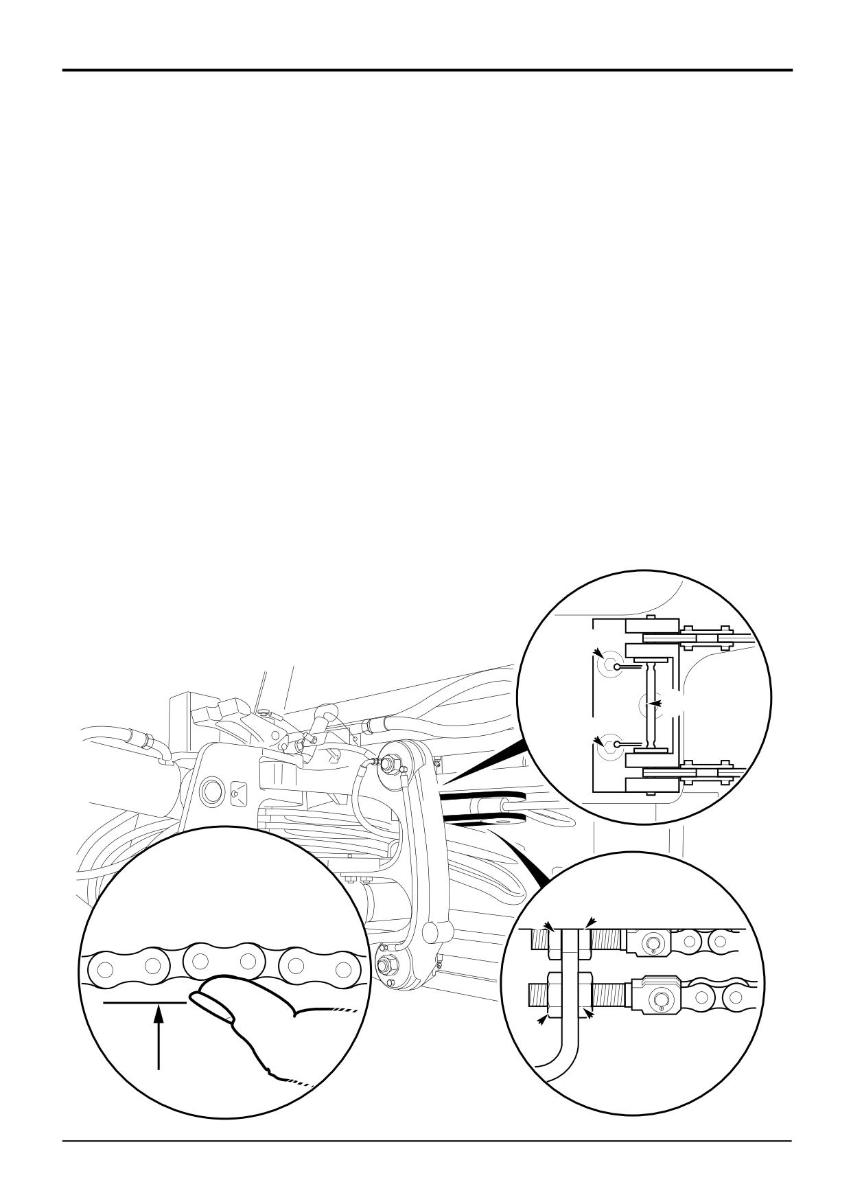
The chain tension should be checked at the initial 100 hours
Removal
service and every 500 hours.
1
Park the machine on firm level ground, engage the
Check and Adjust
parking brake and set the transmission to neutral.
Lower the loader arms to the ground.
1
Park the machine on firm level ground, engage the
parking brake and set the transmission to neutral.
2
Position the carriage centrally and rest the bucket on
Lower the loader arms to the ground.
the ground, remove the starter key.
2
Position the carriage centrally and rest the bucket on
3
Undo and remove nuts B.
the ground, remove the starter key.
4
Remove split pins D and pin E.
3
Check the chain tension which should be 5 to 10mm
(0.19 to 0.39in) deflection A at the mid point. The
5
Withdraw chains from the machine.
tension should be equal for all chains.
Assembly
4
If adjustment is required, slacken locknuts C and adjust
on nuts B as required, tighten locknuts C on
1
Thread the chains around the pulley and secure to the
completion.
carriage with pin E, fit new split pins D.
5
Repeat steps 3 and 4 for the opposite pair of chains.
2
Connect chain adjusters, tension chains as required,
see Check and Adjust.
Note: When there is no thread left for adjustment fit new
chains.
6
Operate the carriage side to side several times and
recheck the deflection.
D
E
D
B C
C
B
A
A326830
9803/3280
Issue 1
Section B
Body & Framework
Section B
30 - 1
Air Conditioning
30 - 1
R
T
S
W
V
X
A401280
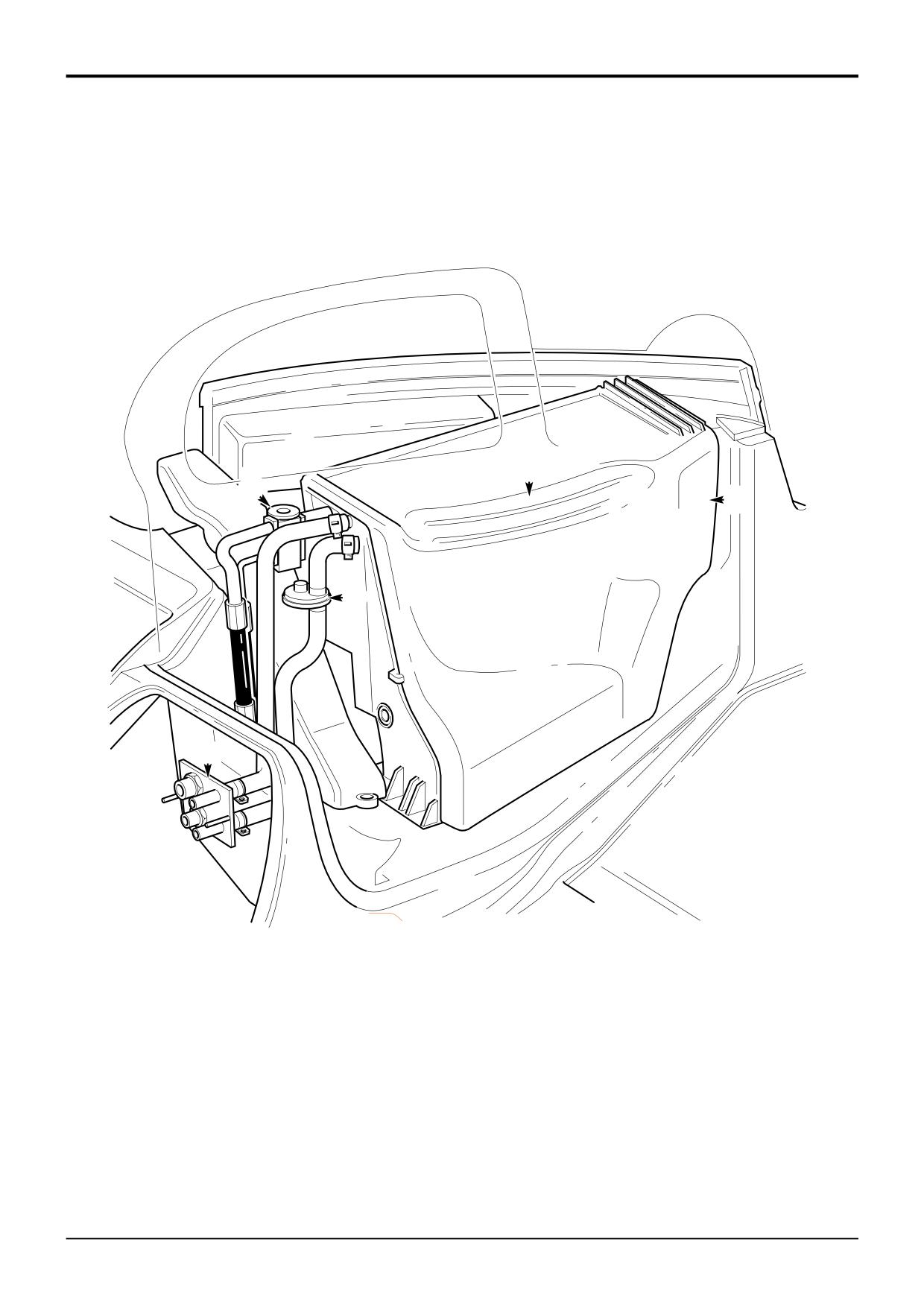
Component Key:
R A/C Controls
S Expansion Valve
T Re-circ Air Inlet
V Water Valve
W HVAC Unit
X Bulkhead Plate
9803/3280
Issue 1