JCB 3CX, 4CX, 214e, 214, 215, 217 & VARIANTS Backhoe Loader. Service Manual - page 3
Section 3
Routine Maintenance
Section 3
26 - 1
Air Conditioning (if fitted)
26 - 1
! WARNING
The air conditioning system is a closed loop system and
contains pressurised refrigerant. No part of the system
should be disconnected until the system has been
X
discharged by a refrigeration engineer or a suitably
trained person. You can be severely frostbitten or injured
by escaping refrigerant.
A
B
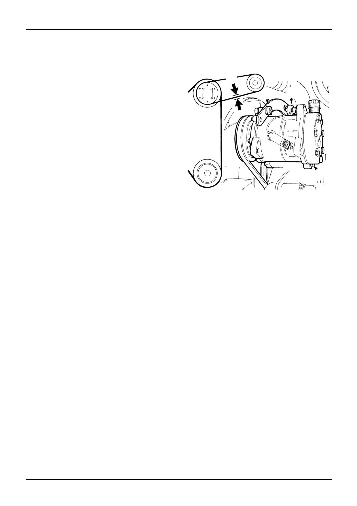
4-3-4-1/2
Adjusting the Compressor Drive Belt
! WARNING
Make sure the engine cannot be started. Disconnect the
battery before doing this job.
2-3-3-5
1
Park the machine on firm level ground, engage the
parking brake and set the transmission to neutral. Raise
and block the loader arms. Lower the backhoe to the
C
ground and stop the engine.
S209393
2
Loosen bolts A, B and C. Position the compressor so
that there is 10 mm (3/8 in) slack at point X.
3
Tighten bolt A, then bolts B and C.
9803/3280
Issue 1
Section 3
Routine Maintenance
Section 3
27 - 1
Hose Burst Protection Valve (if fitted)
27 - 1
The hose burst protection valves (if fitted) prevent the loader
Lowering a Load
or backhoe falling in the event of a hose burst. These valves
may be fitted on rams which raise or lower the loader arms,
During normal operation, the engine must be running before
the boom or the dipper.
a load can be lowered. The following paragraphs describe
how to safely and correctly lower a load in the event of
Checking Hose Burst Protection Valve
engine failure or a hose burst; we recommend that only a
competent maintenance engineer perform the procedures.
1
Raise the loader arms fully. Raise the boom to about
45°. Raise the dipper to the horizontal.
After lowering a load do not use the machine until the
manual over-ride screw has been reset (Loader HBPV) or a
new end cap and valve assembly fitted (Boom HBPV) by a
2
Stop the engine.
qualified engineer, otherwise the valve will not operate as
intended.
3
Using the control levers, try to lower the loader, boom
and dipper. Push the levers fully to the 'lower' position.
! DANGER
If there is any movement, get the hydraulic system
Do not stand underneath the raised load during the
checked by your JCB distributor.
lowering procedure. Stand clear and to one side until the
load has been safely lowered. Make sure that the area is
clear of other people before lowering the load. If you do
not follow these precautions you or others could be
killed or seriously injured.
2-3-5-3
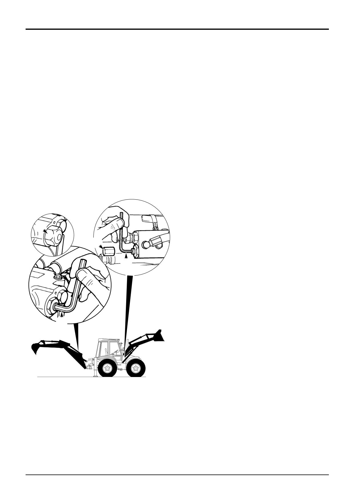
Boom and Dipper Hose Burst Protection Valve (HBPV)
S320930
1
Remove cap A and pierce the warning label.
2
If a hose has burst, position a suitable container to
catch the oil.
A
3
Insert a 6mm allen key into the socket head of screw B.
Slowly turn the allen key in a clockwise direction until
the load just begins move.
C
Burst hose - Lower the boom using screw B, turn the
screw counter-clockwise to slow or stop the load from
lowering.
D
Dead engine - Operate the control lever in the cab to
lower the load.
S170582
Loader Hose Burst Protection Valve (HBPV)
1
Remove cap C from both HBPV check valves on the
loader lift arms.
2
If a hose has burst, position a suitable container to
catch the oil.
B
3
On the burst hose HBPV, insert a 5mm allen key into
the socket head of screw D. Turn the allen key in a
clockwise direction so that the screw winds fully in.
Repeat slowly for the opposite side as the load is now
supported on this HBPV.
Note: Count the number of full turns on each screw for
resetting purposes.
A171340
4
Operate the control lever in the cab to lower the load.
9803/3280
Issue 1
Section 3
Routine Maintenance
Section 3
28 - 1
Service Capacities and Lubricants
28 - 1
ITEM
CAPACITY
FLUID/LUBRICANT
INTERNATIONAL
Litres
UK Gal
SPECIFICATION
Fuel Tank
150
33
Diesel Oil
ASTM D975-66T Nos. 1D, 2D
Engine (Oil) !
2 Wheel Steer Machines
- Build AR
11.0
2.4
JCB Super Multigrade 15W/40
SAE15W/40
- Build AK
10
2.2
-10°C to +50°C (14°F to 122°F)
CF-4/SG
4 Wheel Steer Machines
JCB Super Multigrade 10W/30
SAE10W/30
- Build AK
10.0
2.2
-15°C to +40°C (5°F to 104°F)
CF-4/SG
Engine (Coolant)
23.0
5.1
JCB Four Seasons Antifreeze
ASTM D3306, BS6580
& Summer Coolant/Water
(see Coolant Mixtures)
Syncro Shuttle (2WD) "
14.4
3.2
JCB Extreme Performance
SAE10W
(Below 40 °C, 104 °F)
Syncro Shuttle (4WD) "
15.4
3.4
JCB Extreme Performance
SAE10W
(Below 40 °C, 104 °F)
Powershift 6 speed "
16
3.5
JCB Extreme Performance
SAE10W
(Below 40 °C, 104 °F)
Powershift 4 speed "
15.5
3.4
JCB Extreme Performance
SAE10W
(Below 40 °C, 104 °F)
Front Axle (4WD)
JCB HD90 Gear Oil (without LSD)
API-GL-5
Housing (2WS)
13
2.86
JCB Special Gear Oil Plus (with LSD)
API-GL-4
Housing (4WS) #
18
3.96
Must be suitable for use with limited slip differentials (LSD).
Hubs (x2)
2.0
0.44
Rear Axle (4WS)
JCB Special Gear Oil Plus
API-GL-4
Housing
18
3.96
Must be suitable for use with oil immersed brakes and limited
Hubs (x2)
2.0
0.44
slip differentials (LSD).
Rear Axle (2WS)
23
5.0
Brake System
1.4
0.3
JCB Light Hydraulic Fluid
ISO VG15
! CAUTION: DO NOT USE ORDINARY BRAKE FLUID
Hydraulic System $
130
28.6
JCB High Performance Hydraulic Oil
ISO VG46
(Above 38 °C, 100 °F)
JCB Hydraulic Fluid HP32
ISO VG32
(Below 38 °C, 100 °F)
9803/3280
Issue 1
Section 3
Routine Maintenance
Section 3
28 - 2
Service Capacities and Lubricants
28 - 2
ITEM
CAPACITY
FLUID/LUBRICANT
INTERNATIONAL
Litres
UK Gal
SPECIFICATION
Grease Points
---
JCB HP Grease
Lithium complex NLGI No.2 consistency
including extreme pressure additives
or JCB Special MPL-EP Grease % Lithium based NLGI No.2 consistency
including extreme pressure additives
Extending Dipper
---
Waxoyl &
Electrical
---
As a corrosion and moisture inhibitor all exposed connections should be
connections
coated liberally with petroleum jelly.
Power Sideshift Chains
---
JCB Chain Lubricant
! Note: New engines DO NOT require a running-in period. The engine/machine should be used in a normal work cycle
immediately, glazing of the piston cylinder bores, resulting in excessive oil consumption, could occur if the engine is
gently run-in. Under no circumstances should the engine be allowed to idle for extended periods; (e.g. warming up
without load). Engines of new machines are filled at the factory with JCB 10W/30 Multigrade oil. This oil should be
drained after the first 100 hours operation and the engine filled with the appropriate recommended grade as shown in
the lubrication chart. JCB 10W/30 Multigrade should also be used for the first 100 hours operation whenever a new or
reconditioned engine is fitted to the machine. After the first 100 hours operation, it is essential that the 10W/30 oil is
replaced by the lubricant recommended. The figure quoted is TOTAL system capacity. Use the MIN and MAX marks on
the dipstick when filling the system. Figures quoted within ±0.5 litre (0.11 U.K. gal).
" Note: The figure quoted is TOTAL system capacity. Use the MIN and MAX marks on the dipstick when filling the
system. Figures quoted within ±1.0 litre (0.22 U.K. gal).
$ Note: The total hydraulic system capacity depends on the equipment being used. Fill with all rams closed. Watch level
indicator on hydraulic tank.
% Note: JCB HP Grease is the recommended specification grease, if using JCB Special MPL-EP then the greasing must
be carried out more frequently.
& ! WARNING: Waxoyl contains turpentine substitute, which is inflammable. Keep flames away when applying Waxoyl.
Waxoyl can take a few weeks to dry completely. Keep flames away during the drying period. Do not weld near the
affected area during the drying period. Take the same precautions as for oil to keep Waxoyl off your skin. Do not
breathe the fumes. Apply in a well-ventilated area.
GEN-1-3
# Note: 4WS axles with limited slip differential must use JCB Special Gear Oil Plus.
Coolant Mixtures
! WARNING
Antifreeze can be harmful. Obey the manufacturers instructions when handling neat or diluted antifreeze.
7-3-4-4
The protection provided by JCB Four Seasons Antifreeze and Summer Coolant is shown below. If any other anti-freeze is
used, refer to the manufacturer’s instructions and ensure that a corrosion inhibitor is included. DO NOT use solutions of
more than 60% or less than 50% or damage to the cooling system will occur.
55% Solution - Maintains circulation down to -36 deg C (-33 degF), protects against damage down to -41 deg C (-42 degF)
The strength of the anti-freeze solution must be checked at least once a year, preferably at the beginning of the cold period.
It is an advantage to leave the anti-freeze in all the year round as it gives continued protection against corrosion. Always
renew the anti-freeze every two years. A 50% anti-freeze mixture must be used even if frost protection is not needed. This
gives protection against corrosion and raises the coolants boiling point.
It should be noted that serious damage to the cooling system can occur if corrosion inhibitors are not used.
9803/3280
Issue 1
Section A
Attachments
Section A
i
i
Contents
Page No.
9803/3280
Issue 1
Section B
Body & Framework
Section B
i
i
Contents
Page No.
Service Tools
1 - 1
Slide Hammer Kit Procedure
1 - 4
Rivet Nut Tool Procedure
1 - 5
Technical Data
Air Conditioning (Option)
2 - 1
Basic Operation
Air Conditioning
- R-134a Refrigerant
3 - 1
- System Operation
3 - 1
- System Control
3 - 3
- Safety Procedures
3 - 4
Fault Finding
Air Conditioning
- General Fault Indications
10 - 1
- System Diagnosis
10 - 3
- Wiring Continuity Checks
10 - 8
Service Procedures
Air Conditioning
- Leak Testing
20 - 1
- Tightening Leaking Hoses
20 - 1
- Checking Refrigerant Charge Level
20 - 1
- Refrigerant Charging and Discharging
20 - 2
- Binary Pressure Switch Testing
20 - 7
- Condenser Matrix Cleaning
20 - 8
- Filters - Changing and Cleaning
20 - 9
- Compressor Drive Belt - Adjusting
20 - 10
Glazing
- Removing Broken Glass and Old Sealant
21 - 1
- Preparing and Installing New Glass
21 - 4
Cab ROPS/FOPS Structure - Checks
22 - 1
Engine Panels - Removing and Fitting
23 - 1
Stabiliser Leg - Wear Pad Adjustment
24 - 1
Extending Dipper - Wear Pad Adjustment
25 - 1
Sideshift - Hydraclamp Clearance Setting
26 - 1
Power Sideshift
- Wear Pad Renewal
26 - 2
- Chain Adjustment
26 - 3
Air Conditioning
HVAC*/Air Conditioning Unit
- Removal and Replacement
30 - 1
Blower Unit - Removal and Replacement
30 - 3
Freeze Protection Thermostat
- Removal and Replacement
30 - 3
Evaporator Matrix - Removal and Replacement
30 - 3
Binary Pressure Switch
- Removal and Replacement
30 - 5
*HVAC = Heating, Ventilation and Air Conditioning
9803/3280
Issue 1
Section B
Body & Framework
Section B
ii
ii
Contents
Page No.
Loader Arms - Removal and Replacement
35 - 1
Stabiliser Legs - Removal and Replacement
36 - 1
Kingpost - Removal and Replacement
37 - 1
Boom & Dipper - Removal and Replacement
38 - 1
Hydraulic Tank - Removal and Replacement
39 - 1
Power Sideshift Ram
Removal and Replacement
40 - 1
*
Cab Panels - Removal and Replacement
Side Console
50 - 1
Front/Steering Console
51 - 1
9803/3280
Issue 2*
www.WorkshopManuals.co.ukSection B
Section B
Body & Framework
1 - 1
Service Tools
1 - 1
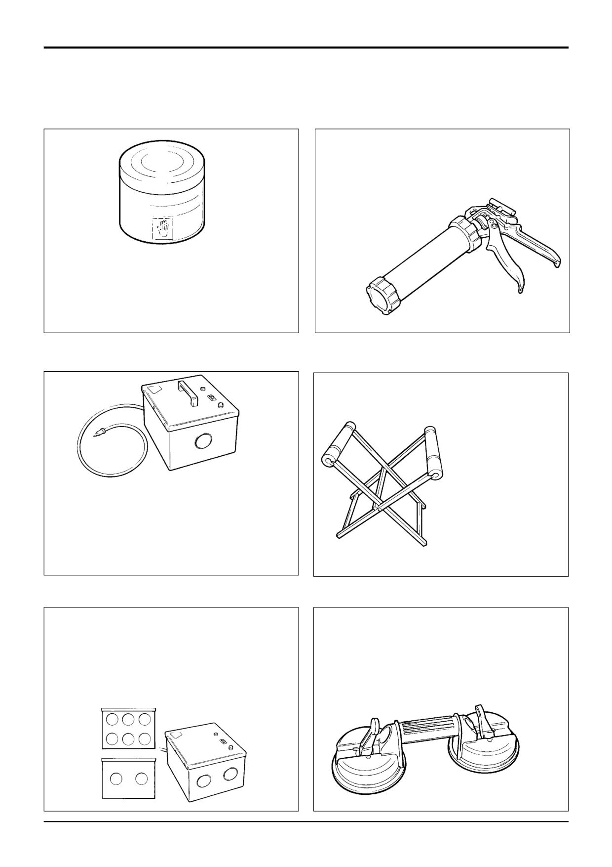
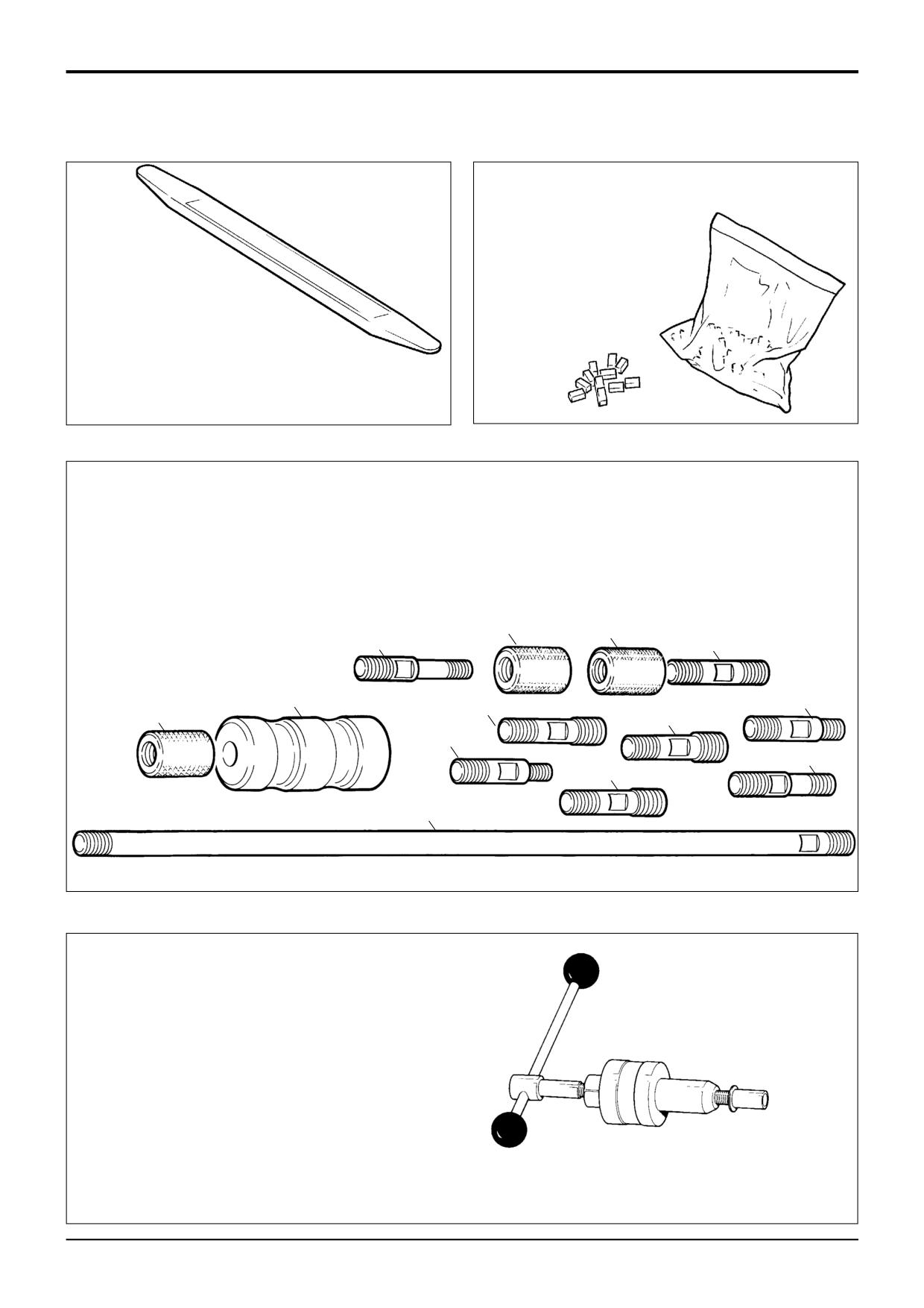
Cartridge Gun - hand operated - essential for the
application of sealants, polyurethane materials etc.
JCB part number
-
892/00845
Hand Cleaner - special blend for the removal of
polyurethane adhesives.
JCB part number - 4104/1310
(454g; 1 lb tub)
S186240
S186270
Folding Stand for
Holding
Glass
-
essential for preparing
new glass prior to
installation.
12V Mobile Oven - 1 cartridge capacity - required to
JCB part number
-
pre-heat adhesive prior to use. It is fitted with a male
892/00843
plug (703/23201) which fits into a female socket
(715/04300).
JCB part number - 992/12300
S186250
S186280
240V Static Oven - available with 2 or 6 cartridge
Glass Lifter - minimum 2 off - essential for glass
capacity - required to pre-heat adhesive prior to use.
installation, 2 required to handle large panes of glass.
No plug supplied. Note: 110V models available upon
Ensure suction cups are protected from damage
request - contact JCB Technical Service.
during storage.
JCB part number:
JCB part number - 892/00842
992/12400 - 2 Cartridge x 240V
992/12600 - 6 Cartridge x 240V
S186300
S186260
9803/3280
Issue 1
www.WorkshopManuals.co.ukSection B
Section B
Body & Framework
1 - 2
Service Tools
1 - 2
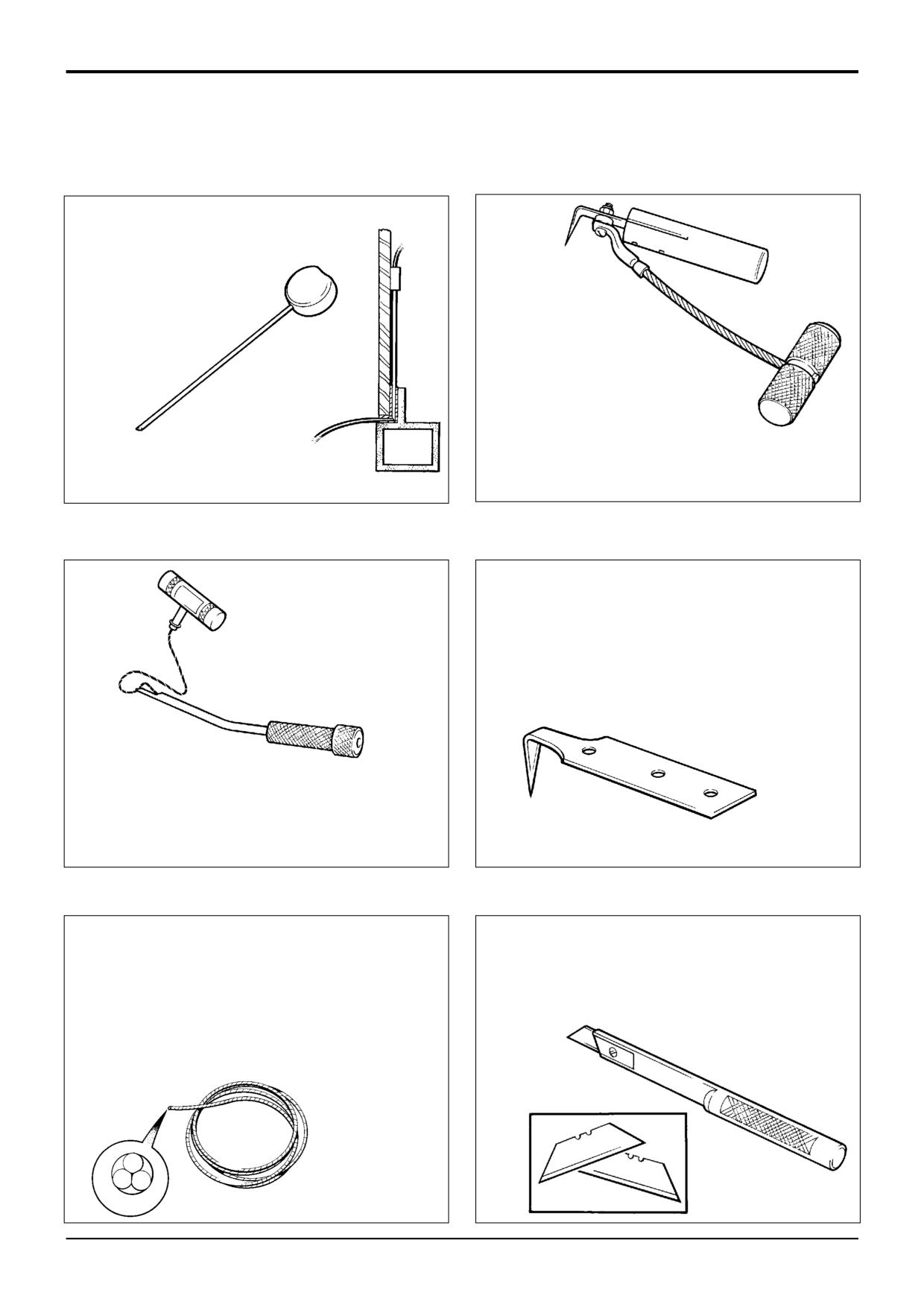
Wire Starter - used to access
braided cutting wire (below)
through original polyurethane
seal.
Cut-Out Knife - used to remove
broken glass.
JCB part number - 992/12800
JCB part number - 892/00848
S186340
S186310
'L' Blades - 25 mm (1 in) cut - replacement blades for
cut-out knife (above).
JCB part number - 992/12801 (unit quantity = 5 off)
Glass Extractor (Handles) - used with braided cutting
wire (below) to cut out broken glass.
JCB part number - 892/00846
S186320
S186350
Long Knife - used to give extended reach for normally
Braided Cutting Wire - consumable heavy duty cut-out
inaccessible areas.
wire used with the glass extraction tool (above).
JCB part number - 892/00844
JCB part number - 892/00849
(approx 25 m length)
S186330
S186360
9803/3280
Issue 1
www.WorkshopManuals.co.ukSection B
Section B
Body & Framework
1 - 3
Service Tools
1 - 3
Rubber Spacer Blocks - used to provide the correct
set clearance between glass edge
and cab frame.
JCB part number - 926/15500
Nylon Spatula
-
(unit quantity = 500 off)
general tool used for
smoothing sealants
- also
used to re-install glass in rubber
glazing because metal tools will chip
the glass edge.
JCB part number - 892/00847
S186470
S186550
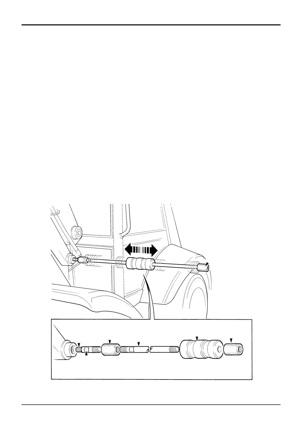
Slide Hammer Kit - 993/68100
1
:993/68101 Slide Hammer
6
:993/68106 Adaptor - M20 x M24
2
:993/68102 End Stops
7
:993/68107 Bar - M20 x M20 X 800MM
3
:993/68103 Adaptor - M20 x 5/8" UNF
8
:993/68108 Adaptor - M20 x 7/8" UNF
4
:993/68104 Adaptor - M20 x 1" UNF
9
:993/68109 Adaptor - M20 x M12
5
:993/68105 Adaptor - M20 x M20
10
:993/68110 Adaptor - M20 x 5/8" UNF (Shoulder)
11
:993/68111 Adaptor - M20 x 1/2" UNF
2
2
11
5
1
3
6
2
4
9
10
8
7
S196910
826/01099
M6 x 16mm Rivet Nut
826/01101
M6 x 19mm Rivet Nut
826/01103
M8 x 18mm Rivet Nut
826/01102
M8 x 21mm Rivet Nut
826/01104
M10 x 23mm Rivet Nut
826/01105
M10 x 26mm Rivet Nut
Installation Tool Available from:
Bollhoff Fastenings Ltd.
Midacre
The Willenhall Estate
Rose Hill
Willenhall
West Midlands, WV13 2JW
S261210
9803/3280
Issue 1
Section B
Body & Framework
Section B
1 - 4
Service Tools
1 - 4
Slide Hammer Kit Procedure
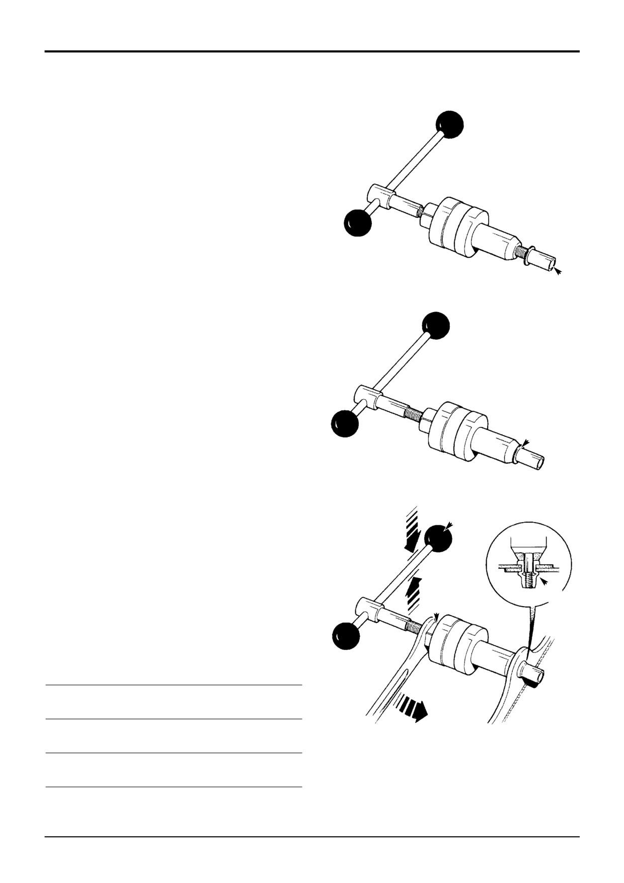
The slide hammer kit is used to remove pivot pins that must
be extracted, i.e. cannot be 'knocked through'. The purpose
of this description is to explain how the kit and the various
components are used to remove the pivot pins.
The adaptors A that form part of the kit have a screwed
thread at each end. One of the threads will always be M20
size, this is to accommodate the end stops, items B and C.
The other end of the adaptor will have varying thread sizes
to suit the different size of threads in the pivot pins.
5
Fit the 'slide hammer', item F, onto the slide bar as
1
Prepare the pivot pin, for instance, if fitted, remove the
shown.
pivot pin retaining bolt.
6
Finally, fit another end stop, item C, at the end of the
2
Determine the thread size of the pivot pin and then fit the
slide bar, as shown. The slide hammer kit is now ready
appropriate adaptor A as shown. Use the spanner flats D
to use.
to securely fit the adaptor.
7
To extract the pivot pin, slide the hammer along the bar
3
Fit an end stop B onto the other end of the adaptor (M20
until it contacts end stop C. Repeat this step until the
thread size), make sure that the adaptor threads are fully
pivot pin is released.
engaged.
8
To remove the slide hammer kit, reverse the steps
4
Fit the 'slide bar' E into the end stop. Again make sure
described above.
that the threads are fully engaged.
C
F
C
B
A
E
D
S196900
9803/3280
Issue 1
Section B
Body & Framework
Section B
1 - 5
Service Tools
1 - 5
Rivet Nut Tool Procedure
A 'Rivet Nut' is a one piece fastener installed 'blind' from
one side of the machine body/framework. The rivet nut is
compressed so that a section of its shank forms an 'upset'
against the machine body/framework, leaving a durable
thread (see illustrations).
Rivet nuts are fitted to various parts of the machine body
and framework. They are used in a number of applications,
for instance, hose clamp and hydraulic valve retention etc.
Various sized rivet nuts are available, see the table below to
determine the size of rivet nut to be used for particular
applications.
If for any reason a new rivet nut requires fitting, then the
A
correct installation procedure must be followed:
1
Drill a hole in the machine body/framework where the
rivet nut is to be fitted. De-burr hole edges.
2
Screw the rivet nut onto the mandrel of the installation
tool. The bottom of the mandrel should be in line with
the bottom of the rivet nut, shown at A.
3
Wind the body of the installation tool down the
threaded mandrel until it touches the head of the rivet
nut, shown at B.
4
Insert the rivet nut (assembled to the tool) into the hole
B
drilled in step 1.
5
Hold handle C and at the same time draw the mandrel
into the installation tool by turning nut D. The rivet nut
will contract in length and form an 'upset' (smooth
bulge) seating itself against the body/framework (see
inset E).
C
Note: The thread of the rivet nut must not be stripped, take
care when 'upsetting' the rivet nut.
6
Remove the installation tool.
E
D
Specifications (all dimensions in mm)
Rivet Nut
Rivet Nut
Material
Rivet
Drill
Thread
Outside
Thickness
Length
Hole
Diameter
Diameter
(Total)
Dia.
M5
7
0.25 - 3.00
14.00
7.10
3.00 - 5.50
17.00
S150970
M6
9
0.50 - 3.00
16.00
9.10
3.00 - 5.50
19.00
M8
11
0.50 - 3.00
18.00
11.10
Note: In an emergency, and if no installation tool is
3.00 - 5.50
21.00
available, it is possible to fit a rivet nut by using a nut and
bolt the same thread diameter as the rivet nut being
M10
13
1.00 - 3.50
23.00
13.10
installed. However, this is not the recommended method.
3.50 - 6.00
26.00
9803/3280
Issue 1
Section B
Body and Framework
Section B
2 - 1
Technical Data
2 - 1
Air Conditioning (Option)
Binary Pressure Switch Settings
Low Pressure
1.96 bar
(2.0 kgf/cm2
28.4 lbf/in2)
High Pressure
27.5 bar
(28 kgf/cm2
400 lbf/in2)
Thermostatic Switch Settings
Cut out
-0.6 °C
(33.0 °F)
Cut in
4.2 °C
(39.5 °F)
Refrigerant
R-134a
1.4 Kg Maximum charge
Oil
PAG Oil
Quantities:
Condenser
1.5 fluid oz.
(42.6 ml)
Evaporator
3.0 fluid oz.
(85.2 ml)
Receiver Drier
0.3 fluid oz.
(8.5 ml)
Compressor
None - pre charged
Hoses
If more than 4 metres of hose is replaced,
then add 0.5 fluid oz. (15 ml) for every metre over 4 metres.
9803/3280
Issue 1
Section B
Body & Framework
Section B
3 - 1
Basic Operation
3 - 1
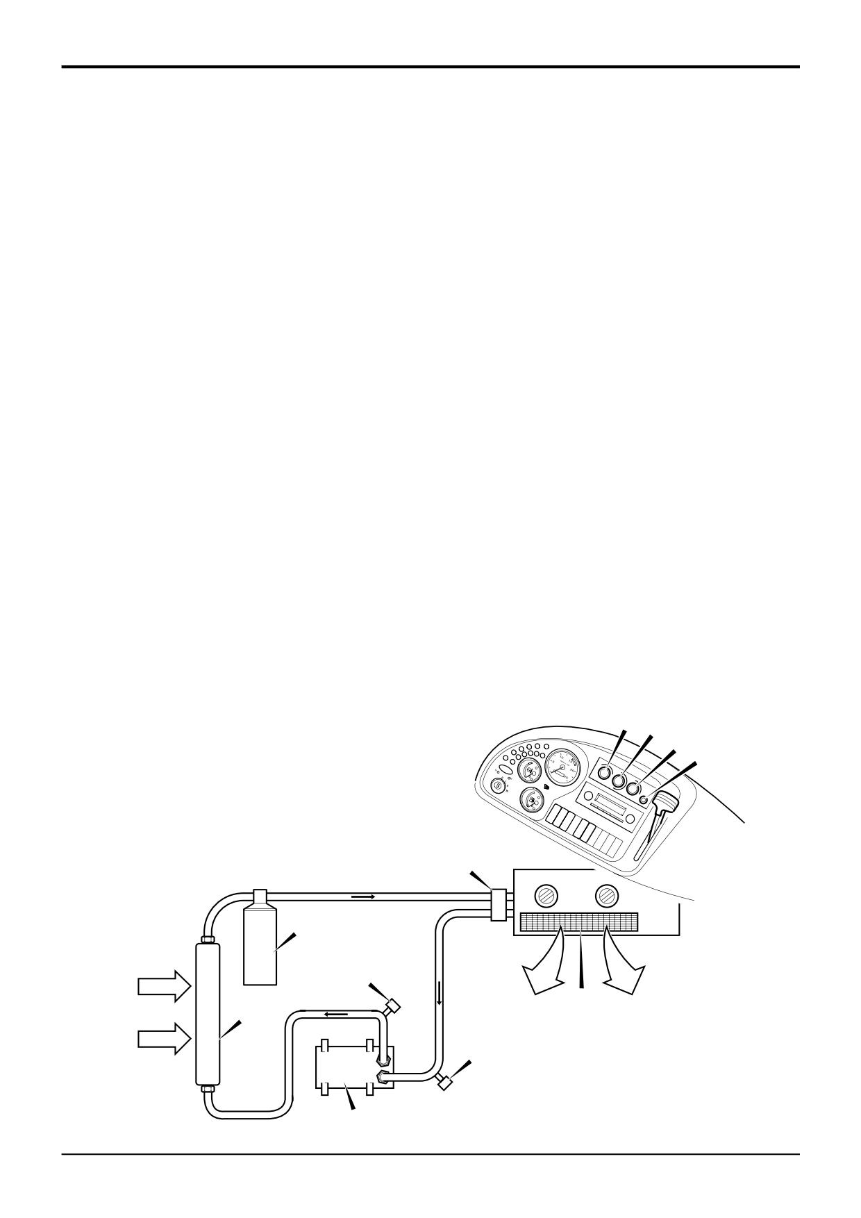
H
J F
G
D
E
C
X
Y
A401370
B
A
9803/3280
Issue 1
Section B
Body & Framework
Section B
3 - 2
Basic Operation
3 - 2
Air Conditioning
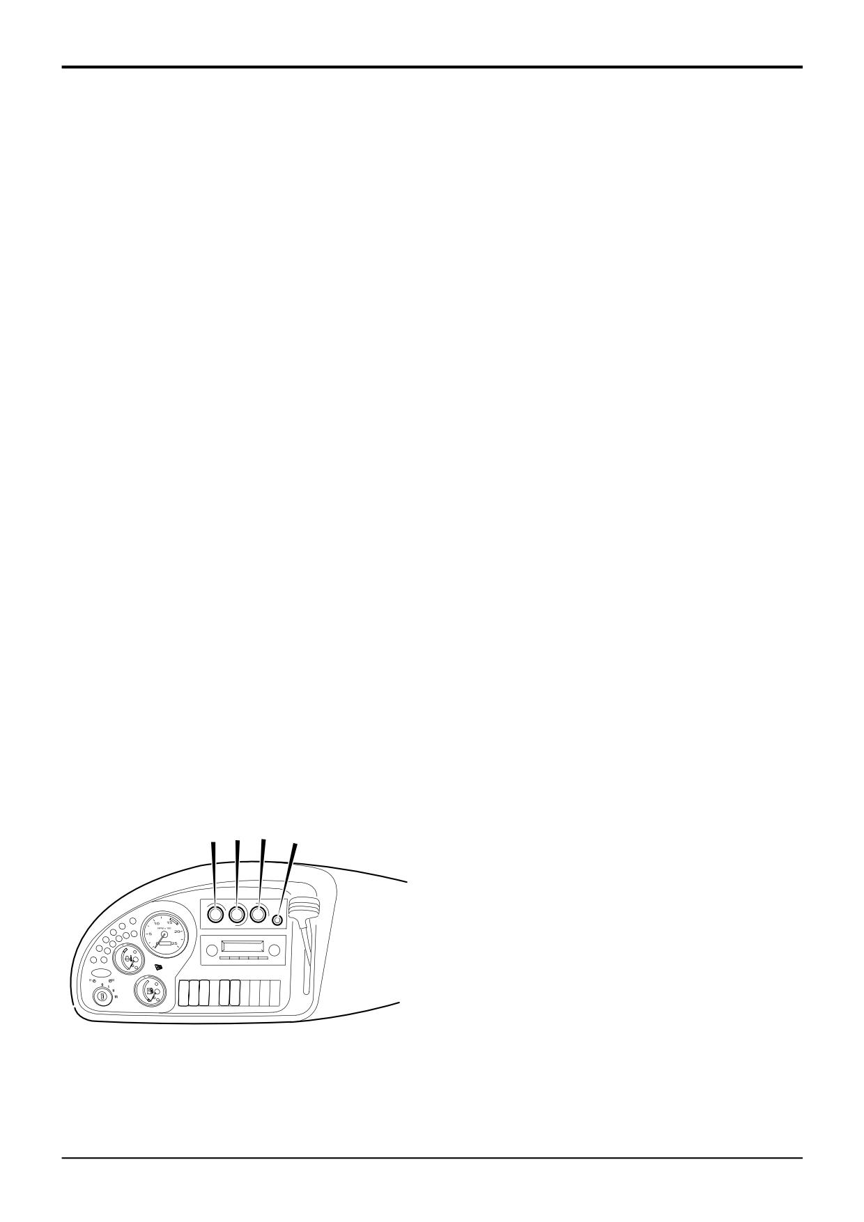
To operate the air conditioning, press switch F to switch the
system on. Press switch G to operate the 3-speed heater
fan. Rotate H to select the desired temperature. Control J
R-134a Refrigerant
enables the operator to select either recirculating air or fresh
air from outside the machine. A combination of both is also
Due to environmental concerns, the use of ozone depleting
obtainable.
chlorofluorocarbons (CFCs) in air conditioning systems is
being gradually phased out.
Air conditioning system power is generated from the engine,
via an electromagnetic clutch to the compressor. Three
The R-12 refrigerant used in some systems contains CFCs
switches, connected in series, are included in the clutch
and is now being replaced by a hydrofluorocarbon (HFC)
supply line, all must be closed for the clutch and therefore
refrigerant R-134a, which does not cause ozone depletion.
the air conditioning system to operate.
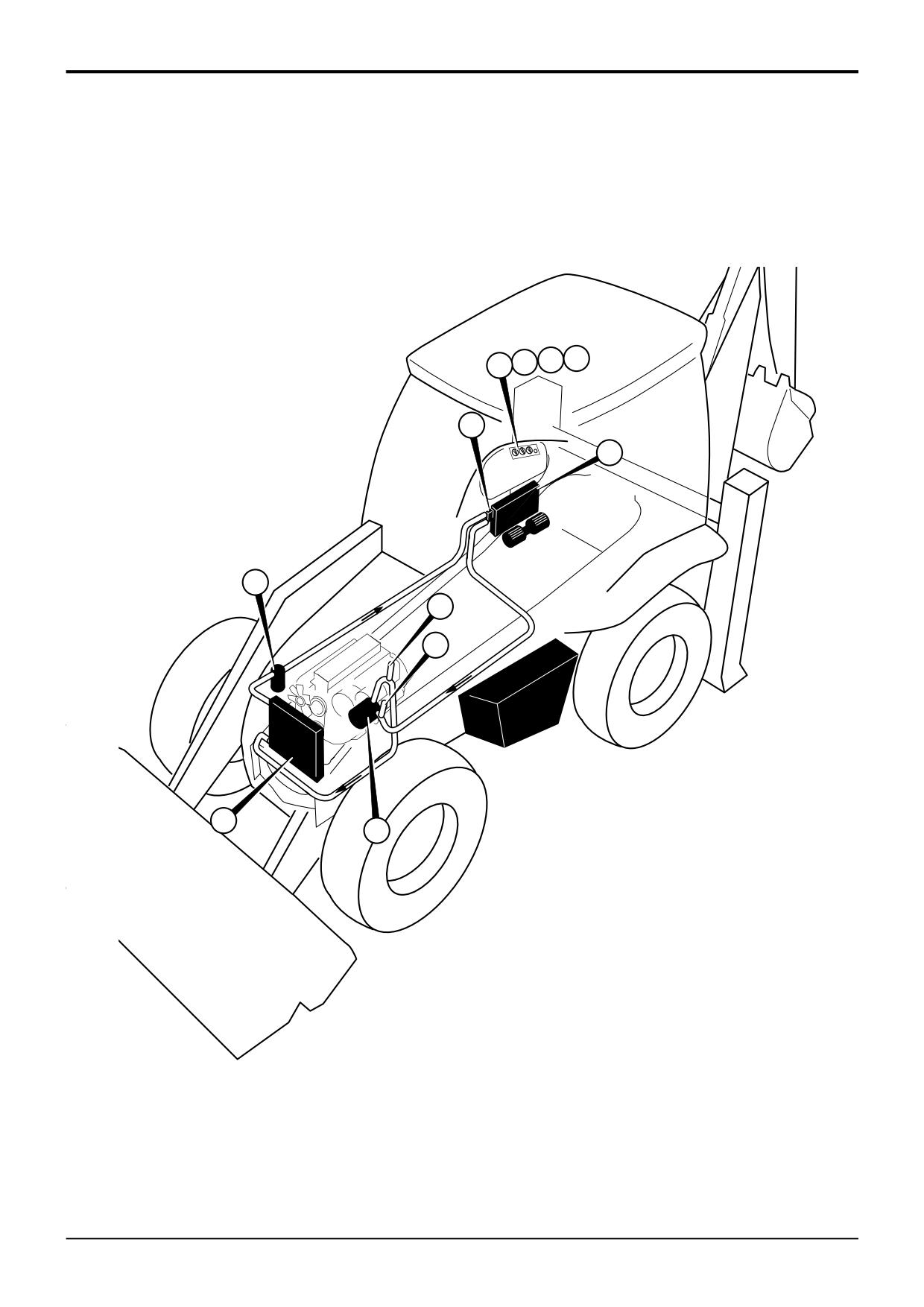
The refrigerant used in the 3CX air conditioning system
is R-134a.
The compressor A draws in low pressure refrigerant gas
from the suction line (evaporator to compressor) and
Air conditioning systems using R-134a refrigerant are not
increases refrigerant pressure through compression. This
compatible with systems using R-12 refrigerant. No attempt
process also increases the refrigerant temperature.
should be made to charge R-134a systems with R-12
refrigerant.
High pressure refrigerant is forced from the compressor to
the condenser B, which is mounted at the front of the
System Operation
engine. Ambient air is drawn across the condenser by the
engine- driven cooling fan. In the condenser, the refrigerant
changes state to a high pressure, high temperature liquid
To maintain optimum operator comfort in warm climates or
but with a lower heat content.
during seasons of high ambient temperature, the air
conditioning system delivers cool, dehumidified air into the
The refrigerant passes through the receiver drier C, which
cab. Cooling is provided by passing the warm ambient air,
contains a desiccant to remove moisture from the system.
together with recirculated air, over an evaporator matrix in
The receiver drier serves as a reservoir for refrigerant and
the air conditioning unit.
also includes a filter to remove foreign particles from the
system.
The air conditioning system is a closed circuit through which
the refrigerant is circulated, its state changing from gas to
The high temperature, high pressure refrigerant is forced by
liquid and back to gas again, as it is forced through the
compressor action into the expansion valve D, which meters
system.
the amount of refrigerant entering the evaporator. In the
expansion valve the refrigerant instantaneously expands to
The major components of the system are the compressor A,
become a low pressure, low temperature liquid.
condenser matrix B, receiver drier C, expansion valve D and
evaporator matrix E.
G H
J
F
D
C
X
E
B
Y
A
A401390
9803/3280
Issue 1
Section B
Body & Framework
Section B
3 - 3
Basic Operation
3 - 3
Air Conditioning
System Operation (cont'd)
System Control
The refrigerant is drawn through the evaporator matrix E by
Control of the system is achieved by the cyclic action of the
the suction of the compressor. The temperature of
compressor's electromagnetic clutch. When current is fed to
refrigerant is now considerably below that of the air being
the field coil of the compressor's clutch, a magnetic field
drawn across the evaporator matrix by the blowers. Heat is
develops between the field coil and the armature which pulls
transferred from the ambient and recirculated air to the
the field coil, complete with clutch assembly, onto the
refrigerant, causing the low pressure liquid to vaporise and
compressor's rotor. Since the clutch assembly is turned
become a low pressure gas. Moisture in the air condenses
constantly by the crankshaft pulley drive belt, the
on the evaporator matrix and is drained away via
compressor armature turns, starting the refrigeration cycle.
condensate.
Current is fed to the field coil through three series switches
Cool de-humidified air is emitted through air vents into the
whose contacts are controlled by the following:
cab.
a The manual A/C ON/OFF switch F in the control
The low temperature, low pressure, high heat content
console.
refrigerant gas, is now drawn by suction back to the
compressor, where the cycle is completed.
b The freeze protection thermostat switch monitoring
the evaporator temperature.
Service connection points X and Y adjacent to the
compressor are provided for connecting the pressure gauge
c The high and low level binary pressure switch.
manifold, when charging/testing the refrigerant. Connection
X high pressure (red) and connection Y low pressure (blue).
The ON/OFF switch F will start the refrigeration cycle
provided that the ambient temperature in the cab is greater
than 0°C and the refrigerant pressure remains within the
specified limits.
The thermostat has its sensor inserted in the evaporator
matrix. It controls the refrigeration cycle by switching the
compressor clutch on and off to prevent freezing of the
condensate on the evaporator matrix.
The high and low level binary pressure switch assembly is
located adjacent to the expansion valve on the HVAC unit. If
the refrigerant pressure exceeds the upper pressure limit
specified or falls below the lower limit, the contacts will open
and the clutch will disengage, closing down the refrigeration
cycle.
Note: Switch settings are given in the technical data, refer to
Technical Data - Air Conditioning (Option).
G H J
F
F A/C ON/OFF Switch
G Turn to switch on the 3-speed heater fan. Turn further
clockwise for faster speeds. It functions only with the
starter switch ON.
H Temperature - Turn anti-clockwise to increase the heat.
J Air Recirculation - Turn clockwise to recirculate air in
the cab. Turn anti-clockwise for fresh air from outsde.
The control can be adjusted to give a combination of
A401550
recirculated air and fresh air.
9803/3280
Issue 1
Section B
Body & Framework
Section B
3 - 4
Basic Operation
3 - 4
Safety Procedures
The air conditioning system includes a pressurised closed
7
When checking the state of the refrigerant at the
circuit containing a non-CFC, environmentally friendly
receiver drier sight glass, it is necessary to run the
refrigerant, Type R-134a. Any service procedure which
engine with the side panel removed and the bonnet
breaks into the closed circuit and therefore requires
raised. Extreme care must be taken to avoid moving
discharging of the system, must only be carried out by
engine parts such as fans, pulleys and belts.
service personnel with specialist knowledge of air
conditioning systems. The following guidelines should be
8
Use caution when working near exposed evaporator
adhered to by all personnel servicing the air conditioning
fins. Painful cuts can be inflicted by the edges of the
system.
fins. Also, damage to the fins will reduce the efficiency
! WARNING
of the system.
The air conditioning system is a closed loop system and
contains pressurised refrigerant. No part of the system
9
Make sure pressure cylinders are not over filled,
should be disconnected until the system has been
particularly when recovering refrigerant.
discharged by a refrigeration engineer. or a suitable
trained person You can be severely frostbitten or injured
10
Disconnect battery before doing any work.
by escaping refrigerant
4-3-4-1/2
! CAUTION
Do not operate the air conditioning system when there is
no refrigerant in the system, otherwise the compressor
will be damaged.
4-3-4-4
1
It is critical that the correct refrigerant (R-134a) is used
and that charging is done only by qualified personnel. It
is illegal to discharge the refrigerant into the
atmosphere but as a precaution in case of accidental
leakage, discharging and charging of the vehicle
refrigerant system must be conducted in a well
ventilated area.
2
Containers of refrigerant should be stored in a cool
environment away from direct sunlight.
! WARNING
Do not carry out welding operations close to the air
conditioning refrigerant circuit. A poisonous gas is
produced when refrigerant comes into contact with
naked flames. Do not smoke or allow naked flames close
to the refrigerant circuit.
BF 1- 9
3
Do Not perform welding operations close to refrigerant
hoses (maintain a distance of at least 0.5m from hoses).
4
Do Not steam clean refrigerant system components.
5
When charging or discharging the refrigerant system,
no smoking or naked flames should be allowed in the
immediate vicinity. The refrigerant does not give off a
poisonous odour, however, when it comes into contact
with a naked flame, a poisonous gas is produced.
6
When handling refrigerant, rubber gloves and goggles
should be worn. Operators should ensure no refrigerant
comes into contact with the skin. Particular care should
be taken when connecting or disconnecting charging
hoses or pressure switches. When these components
are connected to the system, a short release of
refrigerant occurs. This results in a high velocity, very
cold gas being emitted from the connection point.
9803/3280
Issue 1
Section B
Body & Framework
Section B
10 - 1
Fault Finding
10 - 1
Air Conditioning
The system will not function in very low ambient temperatures, therefore tests should be carried out in a warm environment.
It is recommended that, to locate faults on the system accurately and quickly, an electronic leak detector and a refrigerant
pressure gauge should be used. However, leaks can be detected on the system by using soapy water applied to the
suspected leak area and system pressure can be assessed by the state of refrigerant passing through the receiver drier sight
glass. Following sections of the manual deal with the major components of the air conditioning systems and give further fault
finding and maintenance information.
General Fault Indications
There are several indications that may help to determine the fault area on a system not working efficiently:
a)
Poor performance.
Low system pressure -
Evacuate and recharge system.
Condenser matrix air flow restricted -
Remove debris from around matrix using
compressed air or low pressure water.
Air filter blocked -
Remove and replace.
Compressor drive belt too slack -
Adjust to correct tension.
b) Warm or slightly cool air
Expansion valve stuck open or closed - Renew expansion valve.
emitted from unit.
c)
Blower operates on fan
Blower resistor failed -
Renew resistor.
speed 3 only.
Blower motor failed -
Renew complete blower unit.
Blower does not operate.
Fuse blown -
Replace fuse and retest.
d) Compressor clutch
Condenser matrix blockage -
Remove debris from around matrix/renew
continually cuts out.
condenser.
Overcharging of refrigerant system -
Evacuate and recharge system.
Blocked expansion valve/condenser -
Clear blocked component .
Sight Glass Indications
An approximate indication of the condition of the refrigerant can be seen through the receiver/drier sight glass when the
compressor is running. Refer also to Service Procedures - Checking Refrigerant Charge Level.
Clear - No fault indicated unless the system is unable to provide cool air. The indication then is
that the system is completely discharged of refrigerant.
Foam or bubbles - Refrigerant low and in need of charging.
Clouded - Dessicant breakdown in the receiver-drier.
S201520
Note: Sight glass indications cannot always give a positive identification of a problem. Further diagnosis, preferably by a
refrigeration engineer using pressure gauges, is advisable before reaching a definite conclusion.
9803/3280
Issue 1
Section B
Body & Framework
Section B
10 - 2
Fault Finding
10 - 2
Air Conditioning (cont’d)
No Air Conditioning
CHECK
ACTION
1
Are the controls set correctly, i.e. air conditioning
YES:
Check 2
selected, thermostat switch set to coldest position
NO:
Reset controls and retest.
and blower switched on?
2
Is the air conditioning (evaporator) blower working?
YES:
Check 3.
NO:
Check 4.
3
Is the compressor running (visual check of pulley/clutch)?
YES:
Check 9.
NO:
Check 5.
4
Is the air conditioning fuse(s) blown?
YES:
Renew fuse(s) and retest.
NO:
Check 8.
5
Is there a 12V supply to the pressure switch harness?
YES:
Check 6.
Refer to Service Procedures - Pressure Switch Testing
NO:
Check 7.
6
Does the compressor clutch engage with
YES:
Replace pressure switch assembly.
pressure switch assembly bypassed?
NO:
Renew the compressor clutch and retest.
Refer to Service Procedures - Pressure Switch Testing
7
Does the clutch engage with thermostat switch
YES:
Renew thermostat switch and retest.
bypassed?
NO:
Check all electrical connections.
8
Are blower switch and wiring OK?
YES:
Renew blower unit complete.
NO:
Renew switch or wiring.
9
Is sight glass indication OK?
YES:
Check 10.
NO:
Charge check required by refrigeration engineer or
suitably trained person.
10
Is condensor air flow blocked?
YES:
Clean condensor and radiator.
NO:
Check 11.
11
Is evaporator air flow blocked?
YES:
Clean filter and, if necessary the evaporator.
NO:
Call in refrigeration engineer or suitably trained
person.
9803/3280
Issue 1
Section B
Body & Framework
Section B
10 - 3
Fault Finding
10 - 3
Air Conditioning - System Diagnosis
This section gives an overview of the following conditions:
Note: Normal gauge readings will depend on system
components and ambient conditions, make sure that the
Normally Functioning A/C System
valves are closed and the readings are stable and that the
Low R-134a Charge
system has a full charge.
Poor Refrigerant Circulation
No Refrigerant Circulation
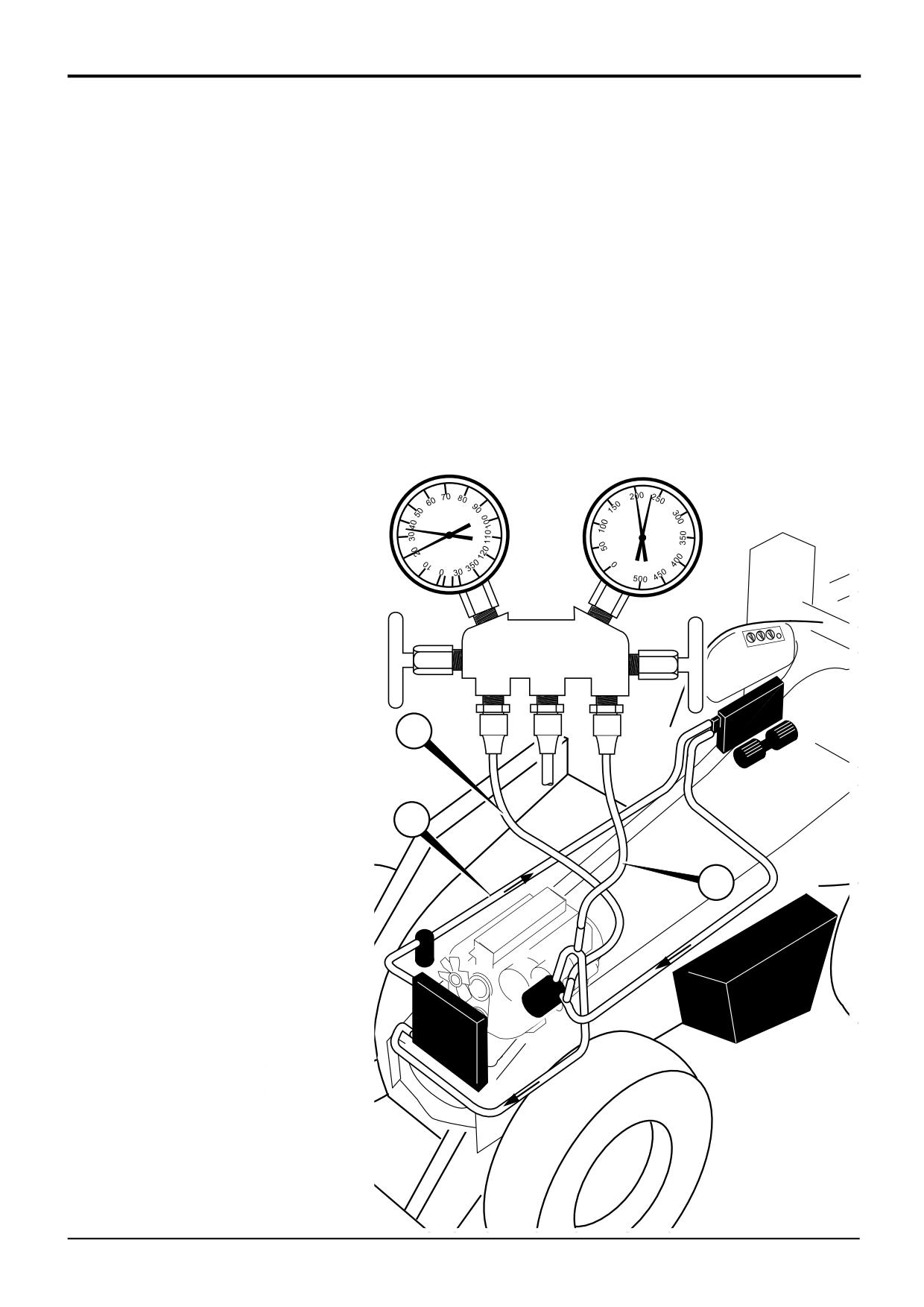
The pressures on the manifold at 25 °C with the engine at
Insufficient Cooling of Condenser
1500 RPM, the blower on maximum and the thermostat set
Air in System
to maximum, should be approximately:
Expansion Valve Improperly Mounted
Compressor Malfunction
Typically, the high pressure is 6 - 8 times the low pressure.
Moisture in the System
LOW SIDE (Blue)
HIGH SIDE (Red)
Normal
Normal
Normally Functioning A/C System
LOW SIDE - 2.0 bar (2.0 kgf/cm2)(29 lbf/in2)
Gauge Readings:
HIGH SIDE - 14.8 bar (15.1 kgf/cm2)(215 lbf/in2)
Low Side Gauge - Normal.
High Side Gauge - Normal.
Other Indications:
Sight Glass - Clear.
Discharge Air - Cold.
B
C
A
Component Key:
A High Pressure/Temperature Gas.
B Low Pressure/Temperature Gas.
C High Pressure Liquid.
A401380
9803/3280
Issue 1
Section B
Body & Framework
Section B
10 - 4
Fault Finding
10 - 4
Air Conditioning
- System Diagnosis (cont'd)
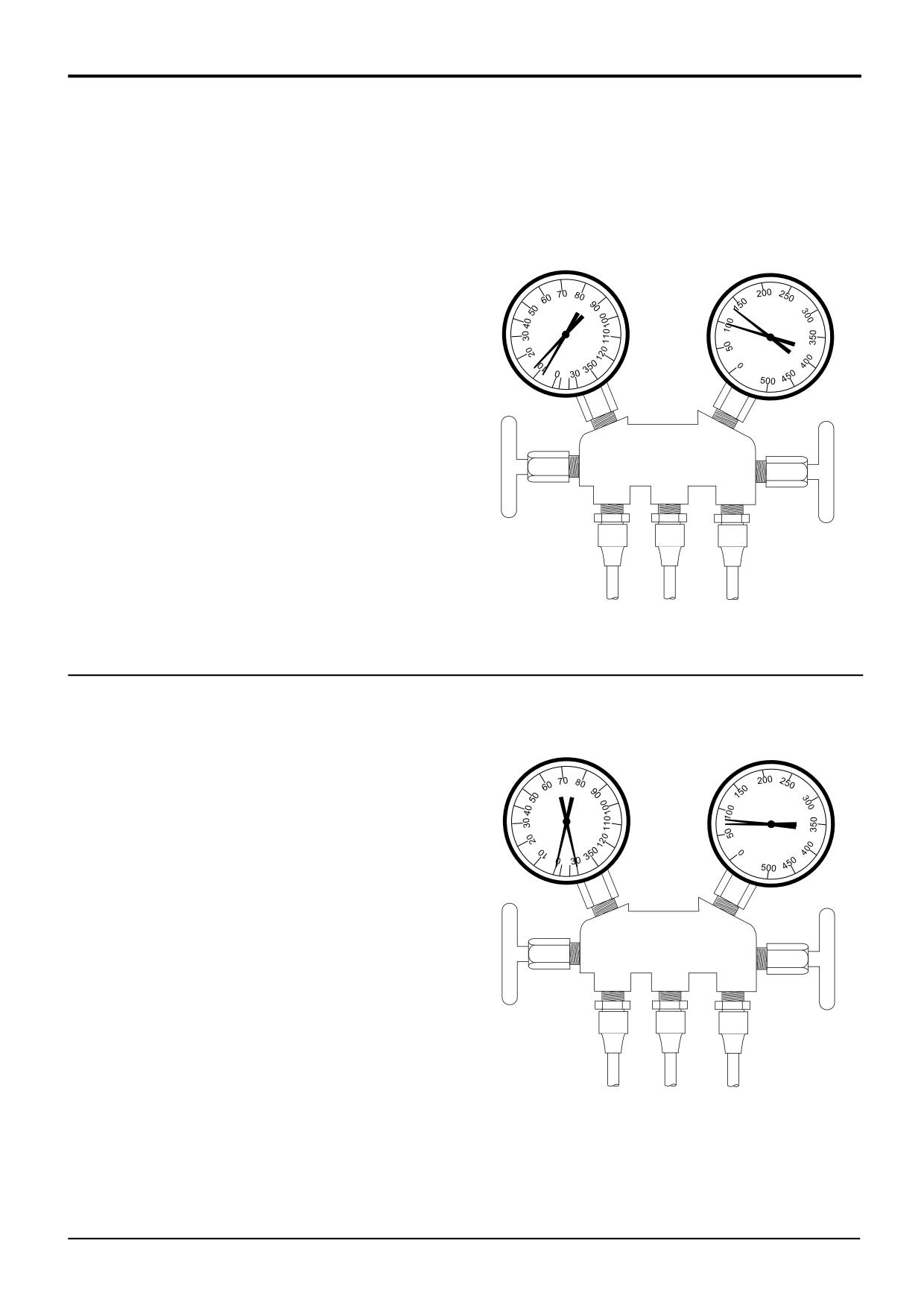
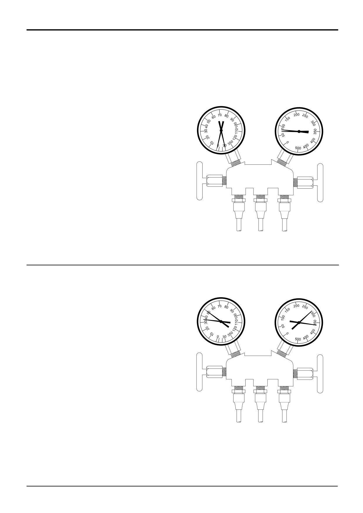
Low R-134a Charge
LOW SIDE (Blue)
HIGH SIDE (Red)
Gauge Readings:
Low
Low
Low Side Gauge - Low.
High Side Gauge - Low.
Other symptoms:
Sight Glass - Bubbles continuously visible.
Diagnosis:
System slightly low on R-134a, due to leak or
incorrect charge.
Correction:
1. Leak test system.
2. Evacuate A/C system.
3. Repair system leaks.
4. Charge system with R-134a.
5. Operate system and check performance.
A268030
LOW SIDE - 0.76 bar (0.77 kgf/cm2)(11 lbf/in2)
HIGH SIDE - 8.3 bar (8.5 kgf/cm2)(121 lbf/in2)
Poor Refrigerant Circulation
LOW SIDE (Blue)
HIGH SIDE (Red)
Zero to negative
Low
Gauge Readings:
Low Side Gauge - Zero to negative.
High Side Gauge - Low.
Other symptoms:
Receiver-Drier - Frost on tubes from receiver-drier
to evaporator unit.
Diagnosis:
Refrigerant flow obstructed by dirt, receiver-drier
clogged.
Correction:
1. Evacuate A/C system.
2. Replace receiver-drier.
3. Charge system with R-134a.
4. Operate system and check performance.
A268040
LOW SIDE - -1.0 bar (-1.1 kgf/cm2)(-15 lbf/in2)
HIGH SIDE - 5.4 bar (5.5 kgf/cm2)(78 lbf/in2)
9803/3280
Issue 1
Section B
Body & Framework
Section B
10 - 5
Fault Finding
10 - 5
Air Conditioning
- System Diagnosis (cont'd)
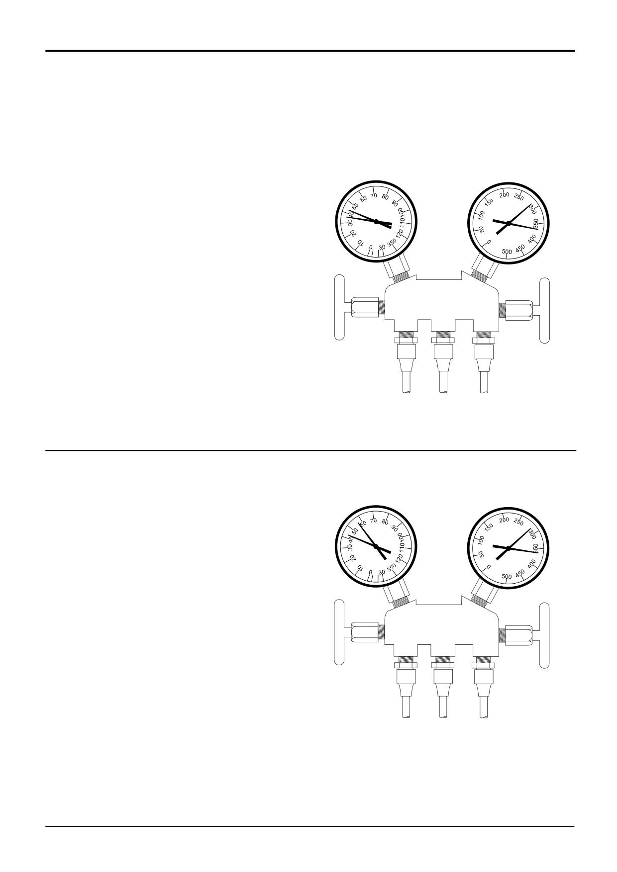
No Refrigerant Circulation
LOW SIDE (Blue)
HIGH SIDE (Red)
Gauge Readings:
Zero to negative
Low
Low Side Gauge - Zero to negative.
High Side Gauge - Low.
Other symptoms:
Receiver-Drier - Frost or moisture on tubes before
and after receiver-drier.
Diagnosis:
Refrigerant flow obstructed by dirt, moisture or
gas leakage from expansion valve heat sensing
tube.
Correction:
1. Evacuate A/C system.
2. Check heat sensing tube at expansion valve.
Replace expansion valve if necessary.
3. Remove expansion valve and attempt removal of
dirt. If dirt cannot be removed, replace expansion
valve.
4. Replace receiver-drier.
A268050
5. Charge system with R-134a.
6. Operate system and check performance.
LOW SIDE - -1.0 bar (-1.1 kgf/cm2)(-15 lbf/in2)
HIGH SIDE - 5.4 bar (5.5 kgf/cm2)(78 lbf/in2)
Insufficient Cooling of Condenser or Refrigerant
Overcharge
LOW SIDE (Blue)
HIGH SIDE (Red)
High
High
Gauge Readings:
Low Side Gauge - High.
High Side Gauge - High.
Other symptoms:
Sight Glass - No bubbles visible even at lower
engine RPM.
Diagnosis:
Refrigerant overcharge, condenser cooling fins
clogged with dirt or cooling fans malfunctioning.
Correction:
1. Clean condenser cooling fins.
2. Check cooling fan operation.
3. Evacuate A/C system.
4. Charge system with R-134a.
5. Operate system and check performance.
A268060
LOW SIDE - 3.0 bar (3.0 kgf/cm2)(43 lbf/in2)
HIGH SIDE - 22.1 bar (22.5 kgf/cm2)(320 lbf/in2)
9803/3280
Issue 1
Section B
Body & Framework
Section B
10 - 6
Fault Finding
10 - 6
Air Conditioning
- System Diagnosis (cont'd)
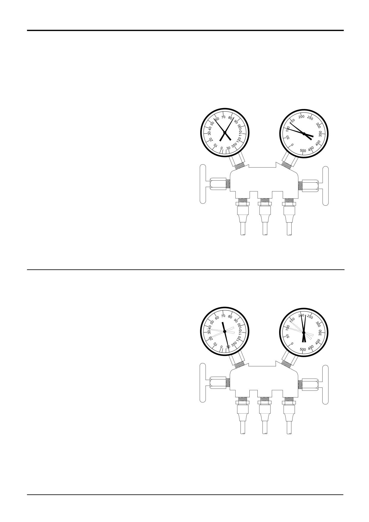
Air in System
LOW SIDE (Blue)
HIGH SIDE (Red)
Gauge Readings:
High
High
Low Side Gauge - High.
High Side Gauge - High.
Other symptoms:
Sight Glass
- Bubbles visible during system
operation.
Pipes - Low pressure pipes are hot to the touch.
Diagnosis:
Air is present in the system, possibly from
inadequate evacuation procedure.
Correction:
1. Evacuate A/C system.
2. Check compressor oil for contamination. Check
compressor for proper oil amount. Correct if
necessary.
3. Charge system with R-134a.
4. Operate system and check performance.
A268070
LOW SIDE - 2.8 bar (2.8 kgf/cm2)(40 lbf/in2)
HIGH SIDE - 22.1 bar (22.5 kgf/cm2)(320 lbf/in2)
Expansion Valve Improperly Mounted or Heat
Sensing Tube Defective (Opening Too Wide)
LOW SIDE (Blue)
HIGH SIDE (Red)
High
High
Gauge Readings:
Low Side Gauge - High.
High Side Gauge - High.
Other symptoms:
Pipes - Large amount of frost or moisture on low side
pipes.
Diagnosis:
Excessive refrigerant in low side pipes possibly
from expansion valve being opened too wide.
Correction:
1. Leak test system.
2. Evacuate A/C system.
3. Repair system leaks.
4. Charge system with R-134a.
5. Operate system and check performance.
A268080
LOW SIDE - 3.5 bar (3.5 kgf/cm2)(50 lbf/in2)
HIGH SIDE - 22.1 bar (22.5 kgf/cm2)(320 lbf/in2)
9803/3280
Issue 1
Section B
Body & Framework
Section B
10 - 7
Fault Finding
10 - 7
Air Conditioning
- System Diagnosis (cont'd)
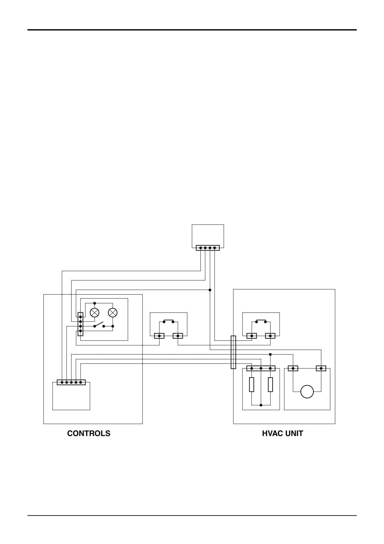
Compressor Malfunction
LOW SIDE (Blue)
HIGH SIDE (Red)
Gauge Readings:
High
Low
Low Side Gauge - High.
High Side Gauge - Low.
Diagnosis:
Internal compressor leak or compressor
mechanically broken.
Correction:
1. Evacuate A/C system.
2. Repair or replace compressor.
3. Charge system with R-134a.
4. Operate system and check performance.
A268090
LOW SIDE - 4.9 bar (5.0 kgf/cm2)(71 lbf/in2)
HIGH SIDE - 8.3 bar (8.5 kgf/cm2)(121 lbf/in2)
Some Moisture in the System
LOW SIDE (Blue)
HIGH SIDE (Red)
Gauge Readings:
Normal to low
Normal to high
Low Side Gauge - Normal, then sometimes drops to
below zero.
High Side Gauge - Normal, then sometimes goes
high.
Diagnosis:
Moisture in system freezes, temporarily stopping
cycle, normal system operation returns when ice
melts.
Correction:
1. Evacuate A/C system.
2. Replace receiver-drier.
3. Remove moisture by repeatedly evacuating
system.
4. Charge system with R-134a.
5. Operate system and check performance.
A268020
LOW SIDE - -2.1 bar (-2.1 kgf/cm2)(-30 lbf/in2)
HIGH SIDE - 14.8 bar (15.0 kgf/cm2)(214 lbf/in2)
9803/3280
Issue 1
www.WorkshopManuals.co.ukSection B
Section B
Body & Framework
10 - 8
Fault Finding
10 - 8
Air Conditioning (cont'd)
Wiring Continuity Checks
Use the illustration below to complete continuity checks on the HVAC/air conditioning system and heater harness wires.The
harness connects to the main machine harness via connector 1. Refer also to the main machine circuit diagram in Section C
Electrics.
Component Key:
1
Main Machine Harness Connector
2
Air Conditioning ON/Off Switch
2A
Panel Illumination Bulb
2B
Switch Illumination Bulb
3
Blower Switch
4
Binary Pressure Switch
5
Freeze Protection Thermostat
6
Blower Speed Resistor
7
Blower Unit Motor
1
A
B
4
5
2
M
3
6
7
A401410
9803/3280
Issue 1