JCB 3CX, 4CX, 214e, 214, 215, 217 & VARIANTS Backhoe Loader. Service Manual - page 1
Section 1
General Information
Section 1
1 - 2
1 - 2
Serial Plates
A Front Axle (2WS machine)
D
B Front Axle (4WS machine)
C Rear Axle (2WS machine)
D Rear Axle (4WS machine)
E Synchro Shuttle Transmission
F Powershift Transmission
S259110
G Engine
A
E
S257580
F
B
S259100
A401030
C
G
S156571
S260120
9803/3280
Issue 1
Section 1
General Information
Section 1
2 - 1
2 - 1
Torque Settings
Use only where no torque setting is specified in the text. Values are for dry threads and may be within three per cent of the
figures stated. For lubricated threads the values should be REDUCED by one third.
UNF Grade 'S' Bolts
Bolt Size
Hexagon (A/F)
Torque Settings
in
(mm)
in
Nm
kgf m
lbf ft
1/4
(6.3)
7/16
14
1.4
10
5/16
(7.9)
1/2
28
2.8
20
3/8
(9.5)
9/16
49
5.0
36
7/16
(11.1)
5/8
78
8.0
58
1/2
(12.7)
3/4
117
12.0
87
9/16
(14.3)
13/16
170
17.3
125
5/8
(15.9)
15/16
238
24.3
175
3/4
(19.0)
11/8
407
41.5
300
7/8
(22.2)
15/16
650
66.3
480
1
(25.4)
11/2
970
99.0
715
11/4
(31.7)
17/8
1940
198.0
1430
11/2
(38.1)
21/4
3390
345.0
2500
Metric Grade 8.8 Bolts
Bolt Size
Hexagon (A/F)
Torque Settings
(mm)
mm
Nm
kgf m
lbf ft
M5
(5)
8
7
0.7
5
M6
(6)
10
12
1.2
9
M8
(8)
13
28
3.0
21
M10
(10)
17
56
5.7
42
M12
(12)
19
98
10
72
M16
(16)
24
244
25
180
M20
(20)
30
476
48
352
M24
(24)
36
822
84
607
M30
(30)
46
1633
166
1205
M36
(36)
55
2854
291
2105
Rivet Nut Bolts/Screws
Bolt Size
Torque Settings (for steel rivet nuts)
(mm)
Nm
kgf m
lbf ft
M3
(3)
1.2
0.12
0.9
M4
(4)
3.0
0.3
2.0
M5
(5)
6.0
0.6
4.5
M6
(6)
10.0
1.0
7.5
M8
(8)
24.0
2.5
18.0
M10
(10)
48.0
4.9
35.5
M12
(12)
82.0
8.4
60.5
Note: All bolts used on JCB machines are high tensile and must not be replaced by bolts of a lesser tensile specification.
9803/3280
Issue 1
Section 1
General Information
Section 1
3 - 1
3 - 1
Service Tools Numerical List
Page No.
Page No.
460/15708
Flow Test Adapter
4 - 13
*
823/10420
Shim Kit - Powershift gearbox,
460/15707
Banjo Bolt
4 - 13
layshaft clutch
4 - 17
1406/0011
Bonded Washer
4 - 7
825/00410
Crowfoot Wrench
4 - 4
1406/0014
Bonded Washer
4 - 7
825/99833
Adapter for 825/00410
4 - 4
1406/0018
Bonded Washer
4 - 7, 13
826/01099
Rivet Nut
4 - 1
1406/0021
Bonded Washer
4 - 6, 4 - 7
826/01101
Rivet Nut
4 - 1
1406/0029
Bonded Washer
4 - 7
826/01102
Rivet Nut
4 - 1
1604/0003
Male Adapter
4 - 7
826/01103
Rivet Nut
4 - 1
1604/0004
Male Adapter
4 - 7, 13
826/01104
Rivet Nut
4 - 1
1604/0006
Male Adapter
4 - 6, 4 - 7
826/01105
Rivet Nut
4 - 1
1604/0008
Adapter
4 - 6
892/00011
Spool Clamp
4 - 8
1606/0003
Male Adapter
4 - 7
892/00041
De-glazing Tool
4 - 19
1606/0004
Male Adapter
4 - 7
892/00047
Adapter
4 - 8
1606/0007
Male Adapter
4 - 7
892/00048
Adapter
4 - 8
1606/0008
Male Adapter
4 - 7
892/00049
Adapter
4 - 8
1606/0009
Male Adapter
4 - 7
892/00051
Adapter
4 - 8
1606/0012
Male Adapter
4 - 6, 4 - 7
892/00055
Blanking Plug
4 - 8
1606/0014
Male Adapter
4 - 7
892/00056
Blanking Plug
4 - 8
1606/0015
Male Adapter
4 - 6, 4 - 7
892/00057
Blanking Plug
4 - 8
1606/0017
Male Adapter
4 - 7
892/00058
Blanking Plug
4 - 8
1612/0006
Adapter
4 - 6
892/00059
Blanking Plug
4 - 8
2401/0222
O-ring
4 - 13
892/00060
Blanking Plug
4 - 8
2403/0110
O-ring
4 - 13
892/00071
Male Adapter
4 - 7
2403/0108
O-ring
4 - 13
892/00074
Female Connector
4 - 8
4101/0651
Retainer (High Strength)
5 - 1
892/00075
Female Connector
4 - 8
4101/0250
Threadlocker and Sealer (10 ml)
5 - 1
892/00076
Female Connector
4 - 8
4101/0251
Threadlocker and Sealer (50 ml)
5 - 1
892/00077
Female Connector
4 - 8
4101/0451
Threadlocker
5 - 1
892/00078
Connector
4 - 6
4102/0502
High Strength Gasketing
5 - 1
892/00137
Micro-Bore Hose 1/4in. BSP, 3 Metres 4 - 7
4102/0551
High Strength Threadlocker
5 - 1
892/00167
Ram Seal Protection Sleeve 90 mm
4 - 9
4102/0933
Clear Silicone Sealant
5 - 1
892/00174
Measuring Cup
4 - 11
4102/1212
Multi-Gasket
5 - 1
892/00179
Bearing Press
4 - 10
4102/1951
Threadseal
5 - 1
892/00180
Seal Fitting Tool
4 - 9
4102/2309
Black Polyurethane Sealant
5 - 1
892/00181
Replacement Plastic Boss
4 - 9
4103/2109
Ultra Fast Adhesive (310ml)
5 - 1
892/00182
Bearing Pad Driver
4 - 12
4104/0251
Activator (Aersol)
5 - 1
892/00223
Hand Pump
4 - 7
4104/0253
Activator (Bottle)
5 - 1
892/00224
Impulse Extractor
4 - 11
4104/1203
Active Wipe 205 (250g)
5 - 1
892/00225
Adapter for Extractor
4 - 11
4104/1206
Active Wipe 205 (30 ml)
5 - 1
892/00253
Pressure Test Kit
4 - 6
4104/1310
Hand Cleaner
4 - 1
892/00255
Pressure Test Adapter
4 - 6
4104/1538
JCB Cleaner & Degreaser
5 - 1
892/00256
Pressure Test Adapter
4 - 6
4104/1557
Cleaner/Degreaser (400 ml)
5 - 1
892/00257
Pressure Test Adapter
4 - 6
4201/4906
Black Primer 206J (30ml)
5 - 1
892/00258
Pressure Test Adapter
4 - 6
816/00017
Adapter
4 - 8
892/00259
Pressure Test Adapter
4 - 6
816/00189
Blanking Cap
4 - 8
892/00260
Pressure Test Adapter
4 - 6
816/00190
Blanking Cap
4 - 8
892/00261
Pressure Test Adapter
4 - 6
816/00193
Blanking Cap
4 - 8
892/00262
Pressure Test 'T' Adapter
4 - 6, 4 - 7
816/00196
Blanking Cap
4 - 8
892/00263
Pressure Test 'T' Adapter
4 - 6
816/00197
Blanking Cap
4 - 8
892/00264
Pressure Test 'T' Adapter
4 - 6
816/00294
Blanking Cap
4 - 8
892/00265
Pressure Test 'T' Adapter
4 - 6
816/00439
Male Adapter
4 - 7
892/00268
Flow Monitoring Unit
4 - 6
816/00440
Male Adapter
4 - 7
892/00269
Sensor Head
4 - 6
816/15007
Male Adapter
4 - 7
892/00270
Load Valve
4 - 6
816/15008
Male Adapter
4 - 7
892/00271
Adapter
4 - 6
816/15118
Pressure Test Adapter
4 - 6
892/00272
Adapter
4 - 6
816/20008
Adapter
4 - 6
892/00273
Sensor Head
4 - 6
816/20013
Adapter
4 - 6
892/00274
Adapter
4 - 7
816/50005
Adapter
4 - 8
892/00275
Adapter
4 - 6
816/50043
Adapter
4 - 8
892/00276
Adapter
4 - 6
816/55038
Pressure Test 'T' Adapter
4 - 6
892/00277
Adapter
4 - 6
816/55040
Pressure Test 'T' Adapter
4 - 6
892/00278
Gauge
4 - 7
816/60096
Adapter
4 - 8
892/00279
Gauge
4 - 7
9803/3280
Issue 2*
Section 1
General Information
Section 1
3 - 2
3 - 2
Service Tools Numerical List
Page No.
Page No.
*
892/00282
Shunt
4 - 4
Shaft Lock Screw
4 - 13
*
892/00283
Tool Kit Case
4 - 4
892/00284
Tachometer
4 - 4
892/01078
Synchro Shuttle Gearbox
892/00285
Hydraulic Oil Temperature Probe
4 - 4
Mainshaft Adjuster
4 - 13
892/00286
Surface Temperature Probe
4 - 4
892/00293
Connector Pipe
4 - 6
892/01076
Synchro Shuttle Support Plate
892/00294
Connector Pipe
4 - 6
Transfer gear end float setting
4 - 13
892/00298
Fluke Meter
4 - 4
892/01082
Powershift - Assembly Cradle
4 - 17
892/00301
Flow Test Adapter
4 - 10
892/01083
Powershift - Assembly tool,
892/00302
Flow Test Adapter
4 - 10
transfer gear
4 - 17
892/00309
ARV Test Kit
4 - 7
892/01084
Powershift - Transfer gear, bearing
892/00333
Heavy Duty Socket
4 - 11
assembly
4 - 17
892/00334
Ram Seal Fitting Tool
4 - 9
892/01085
Powershift - Seal fitting tool
4 - 17
892/00335
ARV Cartridge Removal Tool
4 - 7
926/15500
Rubber Spacer Blocks
4 - 3
892/00706
Test Probe
4 - 6, 4 - 7
992/04000
Torque Multiplier
4 - 12
892/00812
Drive Coupling Spanner
4 - 10
992/04800
Flange Spanner
4 - 12
892/00817
Heavy Duty Socket
4 - 11
992/07608
Bearing Adapter
4 - 10
892/00818
Heavy Duty Socket
4 - 11
992/07609
Bearing Adapter
4 - 10
892/00819
Heavy Duty Socket
4 - 11
992/07610
Bearing Adapter
4 - 10
892/00822
Splined Bolt Socket
4 - 11
992/07611
Bearing Adapter
4 - 10
892/00836
Lifting Wire Assembly
4 - 19
992/07612
Bearing Adapter
4 - 10
892/00842
Glass Lifter
4 - 2
992/07613
Bearing Adapter
4 - 10
892/00843
Folding Stand
4 - 1
992/09100
Spool Clamp
4 - 8
892/00844
Long Knife
4 - 3
992/09200
Charging Tool
4 - 1
892/00845
Cartridge Gun
4 - 1
992/09300
Ram Spanner
4 - 8
892/00846
Glass Extractor (Handles)
4 - 2
992/09400
Ram Spanner
4 - 8
892/00847
Nylon Spatula
4 - 3
992/09500
Ram Spanner
4 - 8
892/00848
Wire Starter
4 - 2
992/09600
Ram Spanner
4 - 8
892/00849
Braided Cutting Wire
4 - 3
992/09700
Ram Spanner
4 - 8
892/00881
Spool Seal Fitting Tool
4 - 7
992/09900
Ram Spanner
4 - 8
892/00882
Alternator Pulley Socket
4 - 5
992/10000
Ram Spanner
4 - 8
892/00891
Wheel Hub Seal - Fitting Tool
4 - 10
992/12300
12V Mobile Oven
4 - 1
892/00918
Setting Tool Kit
4 - 16
992/12400
Static Oven - 2 Cartridge
4 - 2
892/00920
Flow Test Adapter
4 - 10
992/12600
Static Oven - 6 Cartridge
4 - 2
892/00922
12.2” T/C Alignment Tool
4 - 10
992/12800
Cut-Out Knife
4 - 2
892/00948
Charging Kit
4 - 9
992/12801
"L" Blades
4 - 2
892/00949
Pressure Gauge
4 - 9
993/55700
Direct Glazing Kit
5 - 1
892/00956
Timing Pin
4 - 19
993/59500
Impulse Extractor Adapter
4 - 11
892/00964
Test Point (1/8BSP)
4 - 12
993/68100
Slide Hammer Kit
4 - 3
892/00965
Test Point (3/8BSP)
4 - 12
993/69800
Seal Kit
4 - 6
892/00966
Test Point (1/4BSP
4 - 12
993/70111
Breakback Torque Wrench
4 - 15
892/01016
Ram Seal Protection Sleeve 25 mm
4 - 9
993/85700
Battery Tester
4 - 4
892/01017
Ram Seal Protection Sleeve 30 mm
4 - 9
7210/0001
Dummy Plug
4 - 5
892/01018
Ram Seal Protection Sleeve 40 mm
4 - 9
7210/0002
Wire Seal (1.4 - 2.2 mm dia.)
4 - 5
892/01019
Ram Seal Protection Sleeve 50 mm
4 - 9
7210/0003
Wire Seal (2.2 - 2.9 mm dia.)
4 - 5
892/01020
Ram Seal Protection Sleeve 50 mm
4 - 9
7212/0001
2 Way Socket Connector
4 - 5
(slew ram)
7212/0002
2 Way Pin Housing
4 - 5
892/01021
Ram Seal Protection Sleeve 60 mm
4 - 9
7212/0003
2 Way Socket Retainer
4 - 5
892/01022
Ram Seal Protection Sleeve 60 mm
4 - 9
7212/0004
2 Way Pin Retainer
4 - 5
(slew ram)
7213/0001
3 Way Socket Connector
4 - 5
892/01023
Ram Seal Protection Sleeve 65 mm
4 - 9
7213/0002
3 Way Pin Housing
4 - 5
892/01024
Ram Seal Protection Sleeve 70 mm
4 - 9
7213/0003
3 Way Socket Retainer
4 - 5
892/01025
Ram Seal Protection Sleeve 75 mm
4 - 9
7213/0004
3 Way Pin Retainer
4 - 5
892/01026
Ram Seal Protection Sleeve 80 mm
4 - 9
7213/0005
3 Way Socket Connector (DT)
4 - 5
892/01027
Piston Seal Assembly Tool
4 - 9
7213/0006
3 Way Pin Housing (DT)
4 - 5
*
892/01033
Electronic Service Tool Kit
4 - 18
7213/0007
3 Way Socket Retainer (DT)
4 - 5
*
892/01096
Speed Sensor Test Harness
4 - 17
7213/0008
3 Way Pin Retainer (DT)
4 - 5
892/01079
Ring Socket Spanner
7214/0001
4 Way Socket Connector
4 - 5
Mainshaft setting ring
4 - 13
7214/0002
4 Way Pin Housing
4 - 5
892/01080
Ring Socket Spanner
7214/0003
4 Way Socket Retainer
4 - 5
Layshaft setting ring
4 - 13
7214/0004
4 Way Pin Retainer
4 - 5
892/01077
Synchro Shuttle Gearbox Selector
7216/0001
6 Way Socket Connector
4 - 5
9803/3280
Issue 3*
Section 1
General Information
Section 1
3 - 3
3 - 3
Service Tools Numerical List
*
7216/0002
6 Way Pin Housing
4 - 5
The following parts are replacement items for kits and would
*
7216/0003
6 Way Socket Retainer
4 - 5
normally be included in the kit numbers quoted on pages
*
7216/0004
6 Way Pin Retainer
4 - 5
1/3-1 and 1/3-2.
*
7218/0001
8 Way Socket Connector
4 - 5
*
7218/0002
8 Way Pin Housing
4 - 5
Service Tools Numerical List
Page No.
7218/0003
8 Way Socket Retainer
4 - 5
Replacement item for kit no. 892/00180
7218/0004
8 Way Pin Retainer
4 - 5
892/00181
4 - 9
7219/0001
10 Way Socket Connector
4 - 5
7219/0002
10 Way Pin Housing
4 - 5
Replacement items for kit no. 892/00253
7219/0003
10 Way Socket Retainer
4 - 5
892/00201
Replacement Gauge
4 - 6
7219/0004
10 Way Pin Retainer
4 - 5
892/00202
Replacement Gauge
4 - 6
7219/0005
14 Way Socket Connector
4 - 5
892/00203
Replacement Gauge
4 - 6
7219/0006
14 Way Pin Housing
4 - 5
892/00254
Replacement Hose
4 - 6
7219/0007
14 Way Socket Retainer
4 - 5
7219/0008
14 Way Pin Retainer
4 - 5
Replacement items for kit no. 892/00309
892/00340
Test Block Body
4 - 7
892/00341
Setting Body
4 - 7
892/00343
Spanner
4 - 7
892/00345
Anti-Cavitation Lock Out Bung
4 - 7
993/68300
Adjusting Pin
4 - 7
Replacement items for kit no. 993/68100
993/68101
Slide Hammer
4 - 3
993/68102
End Stops
4 - 3
993/68103
Adaptor - M20 x 5/8" UNF
4 - 3
993/68104
Adaptor - M20 x 1" UNF
4 - 3
993/68105
Adaptor - M20 x M20
4 - 3
993/68106
Adaptor - M20 x M24
4 - 3
993/68107
Bar - M20 x M20 X 800MM
4 - 3
993/68108
Adaptor - M20 x 7/8" UNF
4 - 3
993/68109
Adaptor - M20 x M12
4 - 3
993/68110
Adaptor - M20 x 5/8" UNF (Shoulder)
4 - 3
993/68111
Adaptor - M20 x 1/2" UNF
4 - 3
9803/3280
Issue 2*
Section 1
General Information
Section 1
4 - 1
4 - 1
Service Tools (cont'd)
Section B - Body & Framework
826/01099
M6 x 16mm Rivet Nut
826/01101
M6 x 19mm Rivet Nut
826/01103
M8 x 18mm Rivet Nut
826/01102
M8 x 21mm Rivet Nut
826/01104
M10 x 23mm Rivet Nut
826/01105
M10 x 26mm Rivet Nut
Installation Tool Available from:
Bollhoff Fastenings Ltd.
Midacre
The Willenhall Estate
Rose Hill
Willenhall
West Midlands, WV13 2JW
S261210
Cartridge Gun - hand operated - essential for the
application of sealants, polyurethane materials etc.
JCB part number - 892/00845
Hand Cleaner - special blend for the removal of
polyurethane adhesives.
JCB part number - 4104/1310
(454g; 1 lb tub)
S186240
S186270
Folding Stand for
Holding
Glass
-
essential for preparing
new glass prior to
installation.
12V Mobile Oven - 1 cartridge capacity - required to
JCB part number
-
pre-heat adhesive prior to use. It is fitted with a male
892/00843
plug (703/23201) which fits into a female socket
(715/04300).
JCB part number - 992/12300
S186250
S186280
9803/3280
Issue 1
Section 1
General Information
Section 1
4 - 2
4 - 2
Service Tools (cont'd)
Section B - Body & Framework
240V Static Oven - available with 2 or 6 cartridge
Glass Lifter - minimum 2 off - essential for glass
capacity - required to pre-heat adhesive prior to use.
installation, 2 required to handle large panes of glass.
No plug supplied. Note: 110V models available upon
Ensure suction cups are protected from damage
request - contact JCB Technical Service.
during storage.
JCB part number:
JCB part number - 892/00842
992/12400 - 2 Cartridge x 240V
992/12600 - 6 Cartridge x 240V
S186300
S186260
Wire Starter
- used to
access braided cutting wire
(below) through original
polyurethane seal.
Cut-Out Knife - used to
remove broken glass.
JCB part number - 992/12800
JCB part number - 892/00848
S186310
S186340
'L' Blades - 25 mm (1 in) cut - replacement blades for
cut-out knife (above).
JCB part number - 992/12801 (unit quantity = 5 off)
Glass Extractor (Handles) - used with braided cutting
wire (below) to cut out broken glass.
JCB part number - 892/00846
S186320
S186350
9803/3280
Issue 1
Section 1
General Information
Section 1
4 - 3
4 - 3
Service Tools (cont'd)
Section B - Body & Framework
Long Knife - used to give extended reach for normally
Braided Cutting Wire - consumable heavy duty cut-out
inaccessible areas.
wire used with the glass extraction tool (above).
JCB part number - 892/00844
JCB part number - 892/00849
(approx 25 m length)
S186330
S186360
Rubber Spacer Blocks - used to provide the correct
set clearance between glass edge
and cab frame.
JCB part number - 926/15500
Nylon Spatula
-
(unit quantity = 500 off)
general tool used for
smoothing sealants - also
used to re-install glass in
rubber glazing because metal tools
will chip the glass edge.
JCB part number - 892/00847
S186470
S186550
Slide Hammer Kit - 993/68100
1
:993/68101 Slide Hammer
6
:993/68106 Adaptor - M20 x M24
2
:993/68102 End Stops
7
:993/68107 Bar - M20 x M20 X 800MM
3
:993/68103 Adaptor - M20 x 5/8" UNF
8
:993/68108 Adaptor - M20 x 7/8" UNF
4
:993/68104 Adaptor - M20 x 1" UNF
9
:993/68109 Adaptor - M20 x M12
5
:993/68105 Adaptor - M20 x M20
10
:993/68110 Adaptor - M20 x 5/8" UNF (Shoulder)
11
:993/68111 Adaptor - M20 x 1/2" UNF
2
2
11
5
1
3
6
2
4
9
10
8
7
S196910
9803/3280
Issue 1
Section 1
General Information
Section 1
4 - 4
4 - 4
Service Tools (cont'd)
Section C - Electrics
AVO Test Kit
1
892/00283 Tool Kit Case
2
892/00298 Fluke Meter 85
3
892/00286 Surface Temperature Probe
4
892/00284 Venture Microtach Digital Tachometer
5
892/00282
100 amp Shunt - open type
6
892/00285 Hydraulic Temperature Probe
S188231
993/85700
Battery Tester
892/00882
Socket for Alternator Pulley Nut
S239510
S216770
825/00410
15 mm Crowfoot Wrench
825/99833
Adapter
S216200
9803/3280
Issue 1
Section 1
General Information
Section 1
4 - 5
4 - 5
Service Tools (cont'd)
Section C - Electrics
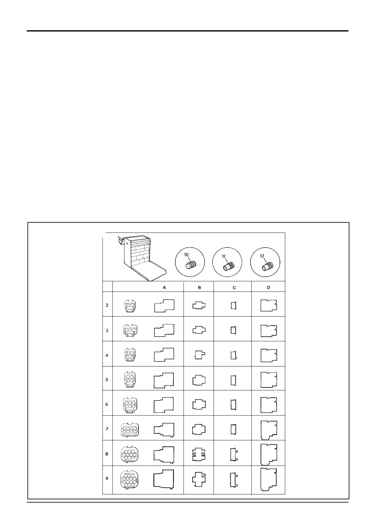
1
Electrical Repair Kit
6A
:7216/0002
6 Way Pin Housing
2A
:7212/0002
2 Way Pin Housing
6B
:7216/0004
6 Way Pin Retainer
2B
:7212/0004
2 Way Pin Retainer
6C
:7216/0003
6 Way Socket Retainer
2C
:7212/0003
2 Way Socket Retainer
6D
:7216/0001
6 Way Socket Connector
2D
:7212/0001
2 Way Socket Connector
7A
:7218/0002
8 Way Pin Housing
3A
:7213/0002
3 Way Pin Housing
7B
:7218/0004
8 Way Pin Retainer
3B
:7213/0004
3 Way Pin Retainer
7C
:7218/0003
8 Way Socket Retainer
3C
:7213/0003
3 Way Socket Retainer
7D
:7218/0001
8 Way Socket Connector
3D
:7213/0001
3 Way Socket Connector
8A
:7219/0002
10 Way Pin Housing
4A
:7213/0006
3 Way Pin Housing (DT)
8B
:7219/0004
10 Way Pin Retainer
4B
:7213/0008
3 Way Pin Retainer (DT)
8C
:7219/0003
10 Way Socket Retainer
4C
:7213/0007
3 Way Socket Retainer (DT)
8D
:7219/0001
10 Way Socket Connector
4D
:7213/0005
3 Way Socket Connector (DT)
9A
:7219/0006
14 Way Pin Housing
5A
:7214/0002
4 Way Pin Housing
9B
:7219/0008
14 Way Pin Retainer
5B
:7214/0004
4 Way Pin Retainer
9C
:7219/0007
14 Way Socket Retainer
5C
:7214/0003
4 Way Socket Retainer
9D
:7219/0005
14 Way Socket Connector
5D
:7214/0001
4 Way Socket Connector
10
:7210/0001
Dummy Plug
11
:7210/0002
Wire Seal (1.4 - 2.2 mm dia.)
12
:7210/0003
Wire Seal (2.2 - 2.9 mm dia.)
1
S188380
9803/3280
Issue 1
Section 1
General Information
Section 1
4 - 6
4 - 6
Service Tools (cont'd)
Section E - Hydraulics
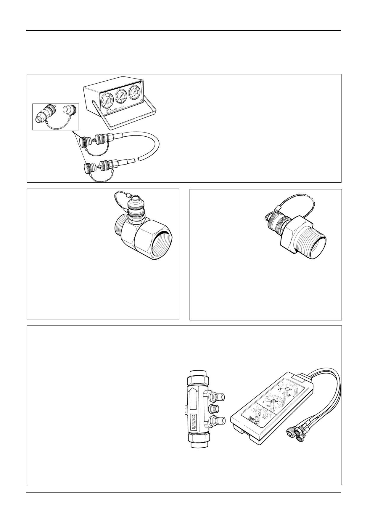
Hydraulic Circuit Pressure Test Kit
892/00253
Pressure Test Kit
:892/00201
Replacement Gauge 0-20 bar (0-300 lbf/in2)
:892/00202
Replacement Gauge 0-40 bar (0-600 lbf/in2)
:892/00203
Replacement Gauge 0-400 bar (0-6000 lbf/in2)
:892/00254
Replacement Hose
S267300
993/69800
Seal Kit for 892/00254 (can also be used with
probe 892/00706)
892/00706
Test Probe
S188121
S188131
Pressure Test Adapters
Pressure Test 'T' Adapters
892/00255
1/4 in BSP x Test Point
892/00256
3/8 in BSP x Test Point
S200141
892/00262
1/4 in M BSP x 1/4 in F BSP x Test Point
892/00257
1/2 in BSP x Test Point
816/55038
3/8 in M BSP x 3/8 in F BSP x Test Point
892/00258
5/8 in BSP x Test Point
816/55040
1/2 in M BSP x 1/2 in F BSP x Test Point
816/15118
3/4 in BSP x Test Point
892/00263
5/8 in M BSP x 5/8 in F BSP x Test Point
892/00259
1 in BSP x Test Point
892/00264
3/4 in M BSP x 3/4 in F BSP x Test Point
892/00260
1.1/4 in BSP x Test Point
892/00265
1 in M BSP x 1 in F BSP x Test Point
892/00261
5/8 in UNF x Test Point
Flow Test Equipment
892/00268
Flow Monitoring Unit
892/00269
Sensor Head 0 - 100 l/min (0 - 22 UK gal/min)
892/00293
Connector Pipe
892/00270
Load Valve
1406/0021
Bonded Washer
1604/0006
Adapter 3/4 in M x 3/4 in M BSP
1612/0006
Adapter 3/4 in F x 3/4 in M BSP
892/00271
Adapter 3/4 in F x 5/8 in M BSP
892/00272
Adapter 5/8 in F x 3/4 in M BSP
816/20008
Adapter 3/4 in F x 1/2 in M BSP
892/00275
Adapter 1/2 in F x 3/4 in M BSP
892/00276
Adapter 3/4 in F x 3/8 in M BSP
892/00277
Adapter 3/8 in F x 3/4 in M BSP
892/00273
Sensor Head 0 - 380 l/min
892/00294
Connector Pipe
1606/0015
Adapter 1.1/4 in M BSP x 1 in M BSP
892/00078
Connector 1 in F x 1 in F BSP
1604/0008
Adapter 1 in M x 1 in M BSP
1606/0012
Adapter 1 in M x 3/4 in M BSP
S188151
816/20013
Adapter 3/4 in F x 1 in M BSP
9803/3280
Issue 1
Section 1
General Information
Section 1
4 - 7
4 - 7
Service Tools (cont'd)
Section E - Hydraulics
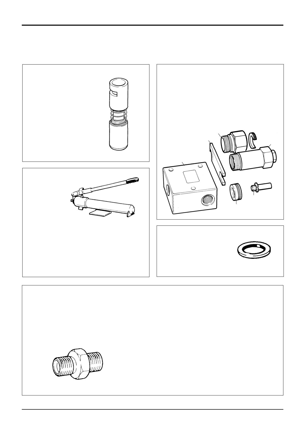
Components for Valve Block A.R.V. Testing
For 4CX Variable Flow machines use 25/201103
892/00881
Valve Spool
892/00309
A.R.V. Pressure Test Kit
Seal Fitting Tool
1
: 892/00340
Test Block Body
2
: 892/00341
Setting Body
3
: 993/68300
Adjusting Pin
4
: 892/00343
Spanner
5
: 892/00345
Anti-cavitation Lock Out Bung
6
892/00335
A.R.V. Cartridge Removal Tool
6
4
2
S261220
1
3
5
S196700
Hand Pump Equipment
892/00223
Hand Pump
Bonded Washers
892/00137
Micro-bore Hose 1/4 in BSP x 3 metres
892/00274
Adapter 1/4 in M BSP x 3/8 in M BSP Taper
1406/0011
1/4 in. BSP
892/00262
1/4 in M BSP x 1/4 in F BSP x Test Point
1406/0018
1/2 in. BSP
892/00706
Test Probe
1406/0014
5/8 in. BSP
892/00278
Gauge 0 - 40 bar (0 - 600 lbf/in2)
1406/0021
3/4 in. BSP
892/00279
Gauge 0 - 400 bar (0 - 6000 lbf/in2)
1406/0029
1.1/4 in. BSP
S188140
S193850
Male Adapters - BSP x NPT (USA only)
Male Adapters - BSP x BSP
816/00439
3/8 in. x 1/4 in.
1606/0003
3/8 in. x 1/4 in.
816/00440
1/2 in. x 1/4 in.
1604/0003
3/8 in. x 3/8 in.
816/15007
3/8 in. x 3/8 in.
892/00071
3/8 in. x 3/8 in. taper
816/15008
1/2 in. x 3/8 in.
1606/0004
1/2 in. x 1/4 in.
1606/0007
1/2 in. x 3/8 in.
1604/0004
1/2 in. x 1/2 in.
1606/0017
5/8 in. x 1/2 in.
1606/0008
3/4 in. x 3/8 in.
1606/0009
3/4 in. x 1/2 in.
1604/0006
3/4 in. x 3/4 in.
1606/0012
3/4 in. x 1 in.
1606/0014
3/4 in. x 1.1/4 in.
1606/0015
1 in. x 1.1/4 in.
S193860
9803/3280
Issue 1
Section 1
General Information
Section 1
4 - 8
4 - 8
Service Tools (cont'd)
Section E - Hydraulics
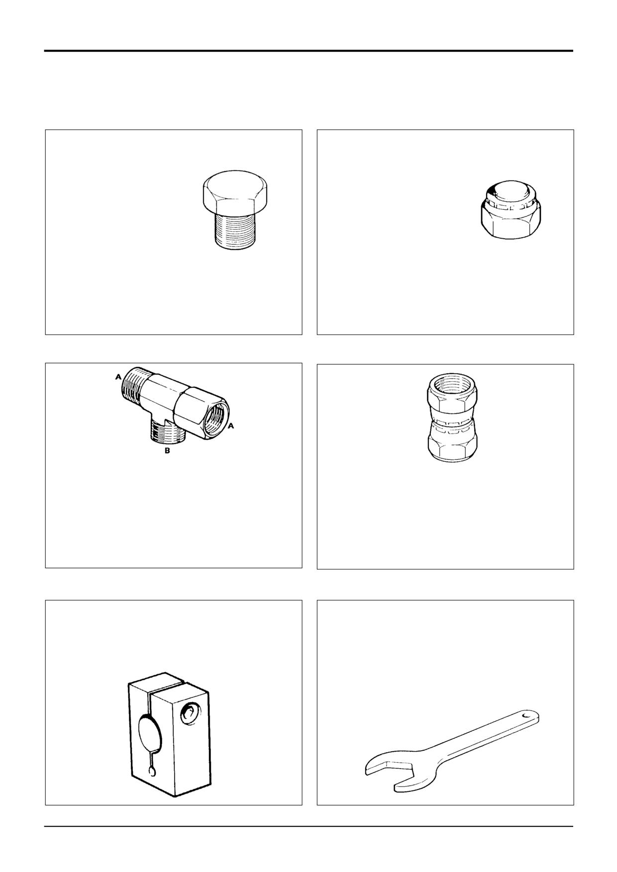
Female Cone Blanking Plug
892/00055
1/4 in. BSP
Male Cone Blanking Cap
892/00056
3/8 in. BSP
816/00294
1/4 in. BSP
892/00057
1/2 in. BSP
816/00189
3/8 in. BSP
892/00058
5/8 in. BSP
816/00190
1/2 in. BSP
892/00059
3/4 in. BSP
816/00197
5/8 in. BSP
892/00060
1 in. BSP
816/00196
3/4 in. BSP
816/00193
1 in. BSP
S193880
S193870
S193890
S193900
892/00047
3/8 in. BSP (A) x 1/4 in. BSP (B)
892/00048
1/2 in. BSP (A) x 1/4 in. BSP (B)
892/00049
5/8 in. BSP (A) x 1/4 in. BSP (B)
Female Connectors
816/50043
3/4 in. BSP (A) x 1/4 in. BSP (B)
892/00051
1 in. BSP (A) x 1/4 in. BSP (B)
892/00074
3/8 in. BSP x 3/8 in. BSP
816/50005
1/2 in. BSP (A) x 1/2 in. BSP (B)
892/00075
1/2 in. BSP x 1/2 in. BSP
816/60096
3/4 in. BSP (A) x 3/4 in. BSP (B)
892/00076
5/8 in. BSP x 5/8 in. BSP
816/00017
1 in. BSP (A) x 1 in. BSP (B)
892/00077
3/4 in. BSP x 3/4 in. BSP
992/09100
Excavator Spool Clamp
Hexagon Spanners for Ram Pistons and End Caps
892/00011
Spool Clamp
992/09300
55mm A/F
992/09400
65mm A/F
992/09500
75mm A/F
992/09600
85mm A/F
992/09700
95mm A/F
992/09900
115mm A/F
992/10000
125mm A/F
S216210
S193930
9803/3280
Issue 1
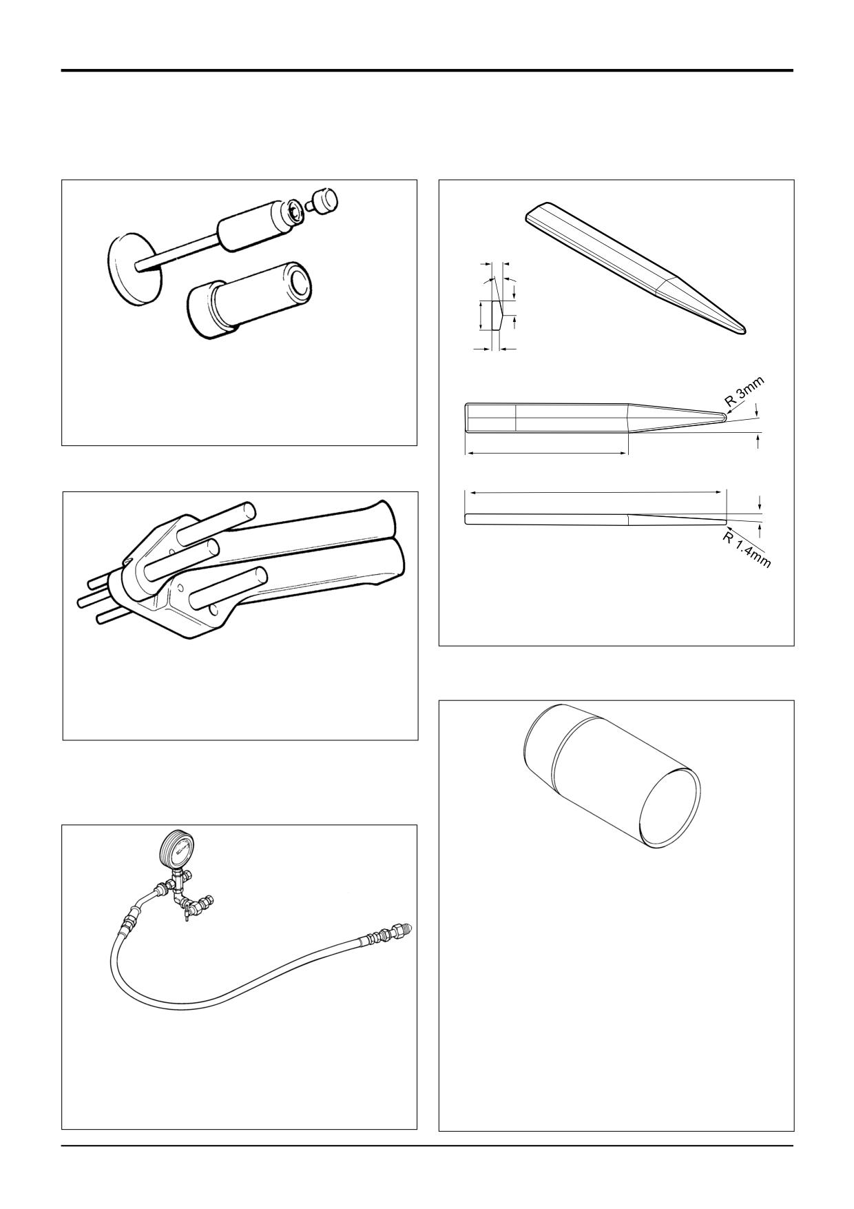
Section 1
General Information
Section 1
4 - 9
4 - 9
Service Tools (cont'd)
Section E - Hydraulics
7mm
o
11
S216230
10mm
20mm
5mm
892/00180
Seal Fitting Tool for fitting 'O' ring and
kin ring to Hydraulic Steer Unit
892/00181
Replacement Plastic Boss
110mm
175mm
3o
892/01027
Piston Seal Assembly Tool
338500
S216250
892/00334
Ram Seal Fitting Tool
S338410
Ram Seal Protection Sleeves
892/01016
For 25 mm Rod Diameter
892/01017
For 30 mm Rod Diameter
892/01018
For 40 mm Rod Diameter
892/01019
For 50 mm Rod Diameter
892/01020
For 50 mm Rod Diameter (slew ram)
892/01021
For 60 mm Rod Diameter
892/01022
For 60 mm Rod Diameter (slew ram)
892/01023
For 65 mm Rod Diameter
S308271
892/01024
For 70 mm Rod Diameter
892/01025
For 75 mm Rod Diameter
892/00948
Charging Kit (without gauge)
892/01026
For 80 mm Rod Diameter
892/00949
Gauge
892/00167
For 90 mm Rod Diameter
9803/3280
Issue 1
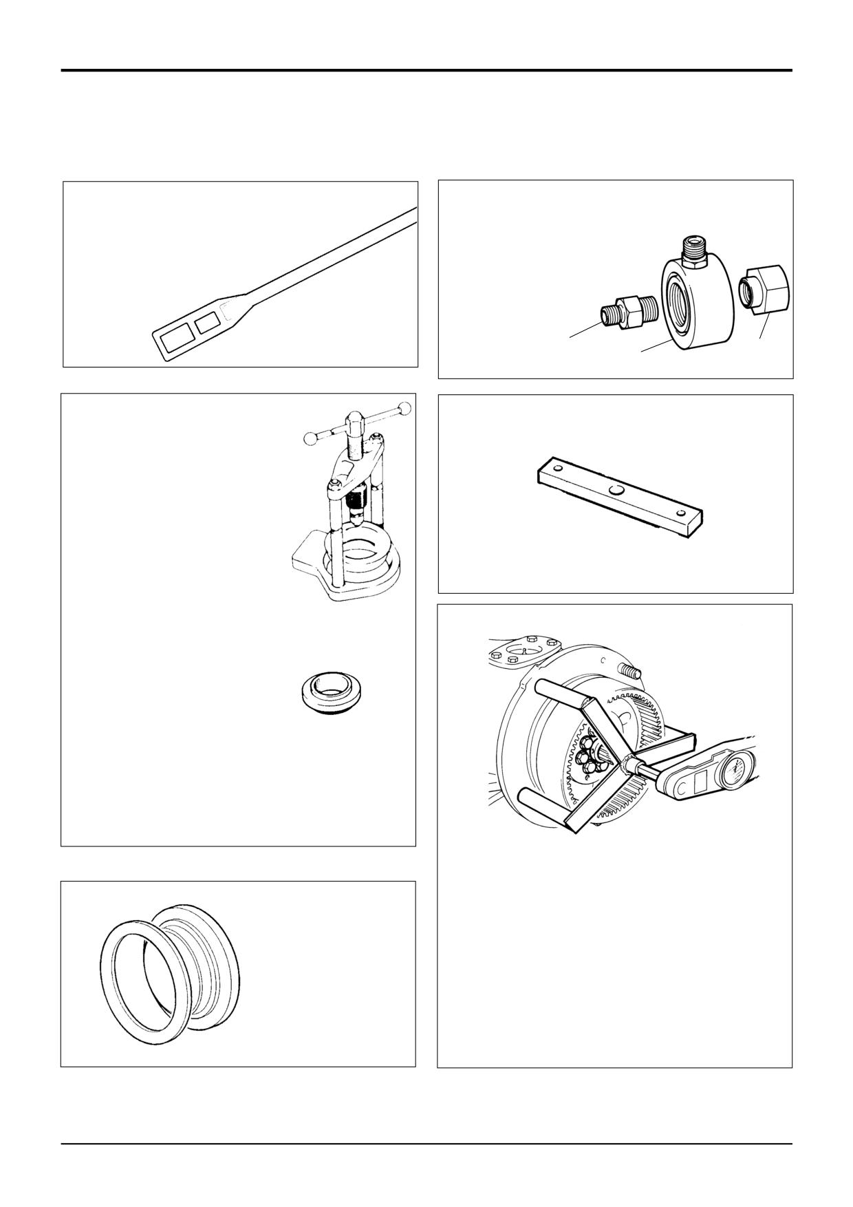
Section 1
General Information
Section 1
4 - 10
4 - 10
Service Tools (cont'd)
Section F - Transmission
A
892/00920 Flow Test Adapter
892/00812
Drive Coupling Spanner for front
B
892/00301 Flow Test Adapter
axle and gearbox yoke
C
892/00302 Flow Test Adapter
couplings
S196720
A
S266880
C
B
892/00922
12.2” Torque Converter Alignment Tool
892/00179
Bearing Press (use with
appropriate adapters)
S267260
S188200
992/07608
Bearing Adapter
992/07609
Bearing Adapter
992/07610
Bearing Adapter
992/07611
Bearing Adapter
992/07612
Bearing Adapter
992/07613
Bearing Adapter
S188160
S261230
Torque Measuring Tool for Wheel Hub Seals
Manufacture locally, procedures in this manual show
checking the wheel hub seal using a rolling force.
892/00891
However, the torque can be measured using above
locally manufactured tool.
Fitting Tool Assembly for
Wheel Hub Seals
Bearing rolling torque is 12 to 22 Nm (9 to 16 lbf ft)
excluding seal drag. Maximum permissible including
seal drag is 40 Nm (29.5 lbf ft).
S227760
9803/3280
Issue 1
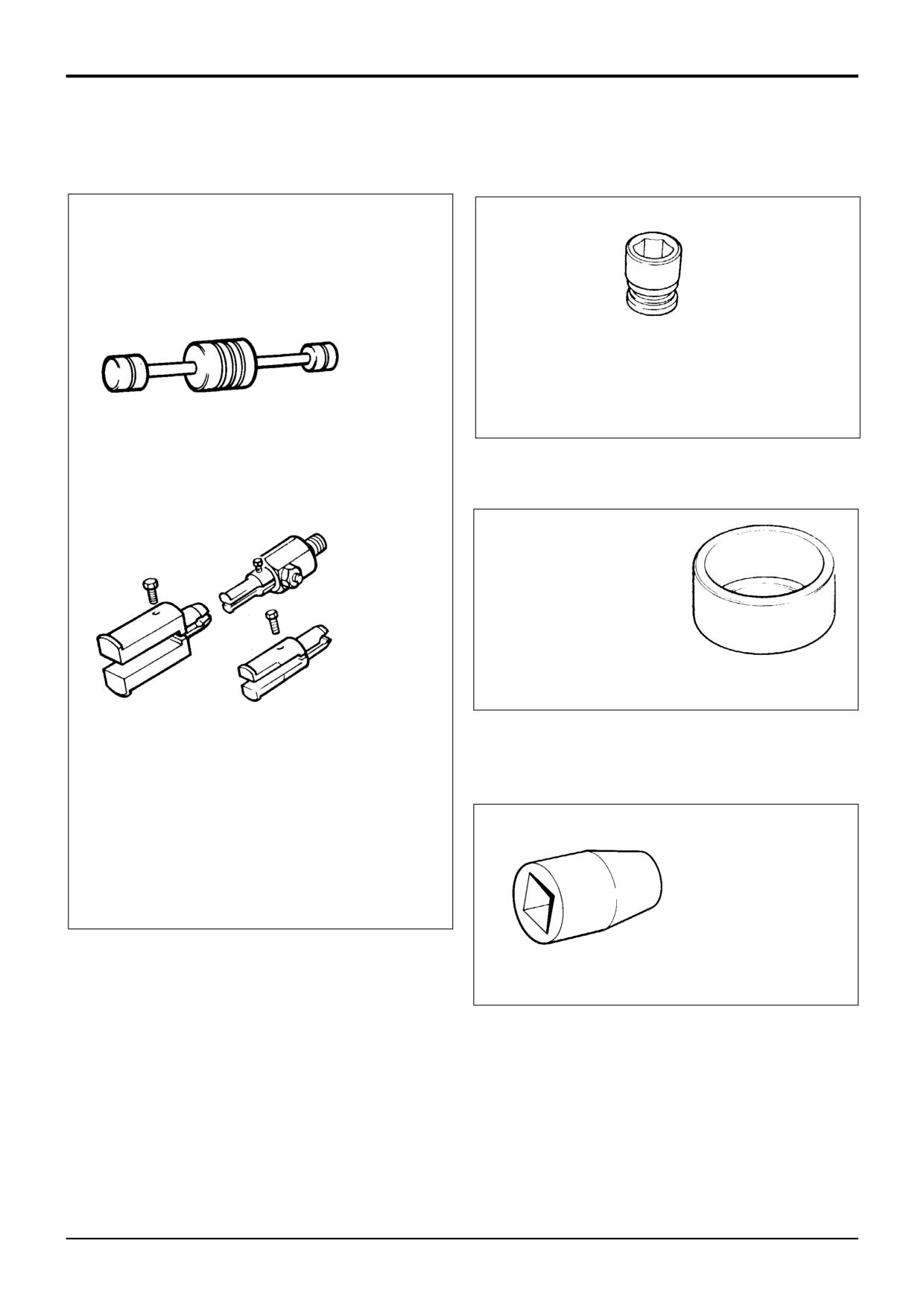
Section 1
General Information
Section 1
4 - 11
4 - 11
Service Tools (cont'd)
Section F - Transmission
892/00224
Impulse Extractor Set for Hub Bearing Seals
S216290
892/00817
17 mm A/F x 3/4in. square drive
892/00818
22 mm A/F x 3/4in. square drive
892/00819
15 mm A/F x 1/2in. square drive
892/00333
19 mm A/F x 3/4in. square drive
S197070
892/00174
Measuring Cup - Pinion Head Bearing
S190770
892/00225
Adapter - Impulse Extractor
Small
17mm to 25mm
Medium 25mm to 45mm
Large
45mm to 80mm
993/59500
Adapter - Impulse Extractor (syncro
shuttle and powershift transmission)
892/00822
Splined Bolt Socket for
driveshafts
S197060
9803/3280
Issue 1
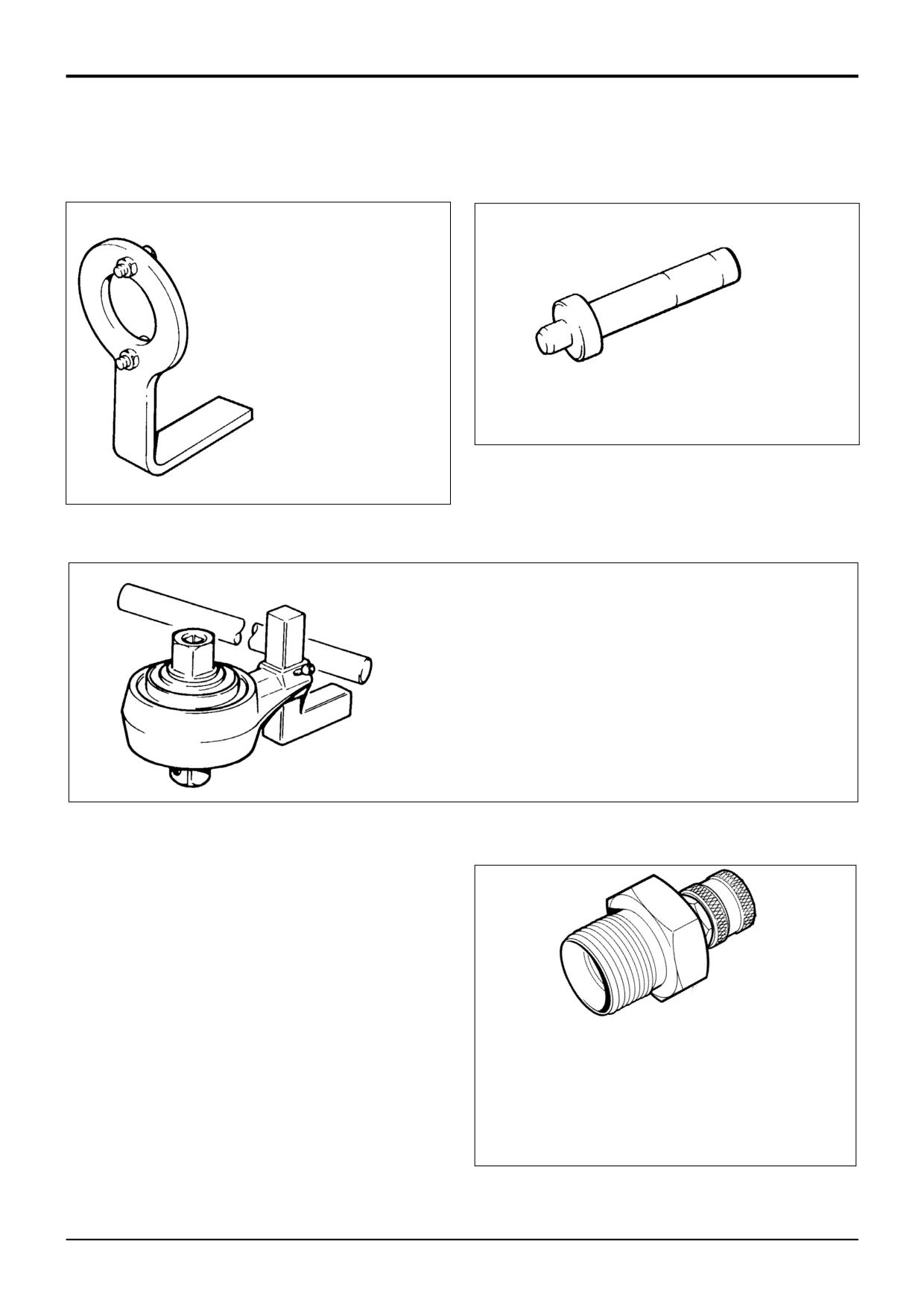
Section 1
General Information
Section 1
4 - 12
4 - 12
Service Tools (cont'd)
Section F - Transmission
992/04800
Flange Spanner - for locking pinion
flange while pinion nut is slackened or
torque set
S216310
892/00182
Bearing Pad Driver
S197040
992/04000
Torque Multiplier (use in conjunction with a torque wrench to give a
5:1 multiplication when tightening pinion nuts)
S197030
S316250
Test Point
1
892/00964
Test point (1/8 BSP) Powershift
2
892/00965
Test point (3/8 BSP) Powershift
3
892/00966
Test point (1/4 BSP) Syncro Shuttle
9803/3280
Issue 1
Section 1
General Information
Section 1
4 - 13
4 - 13
Service Tools (cont'd)
Section F - Transmission
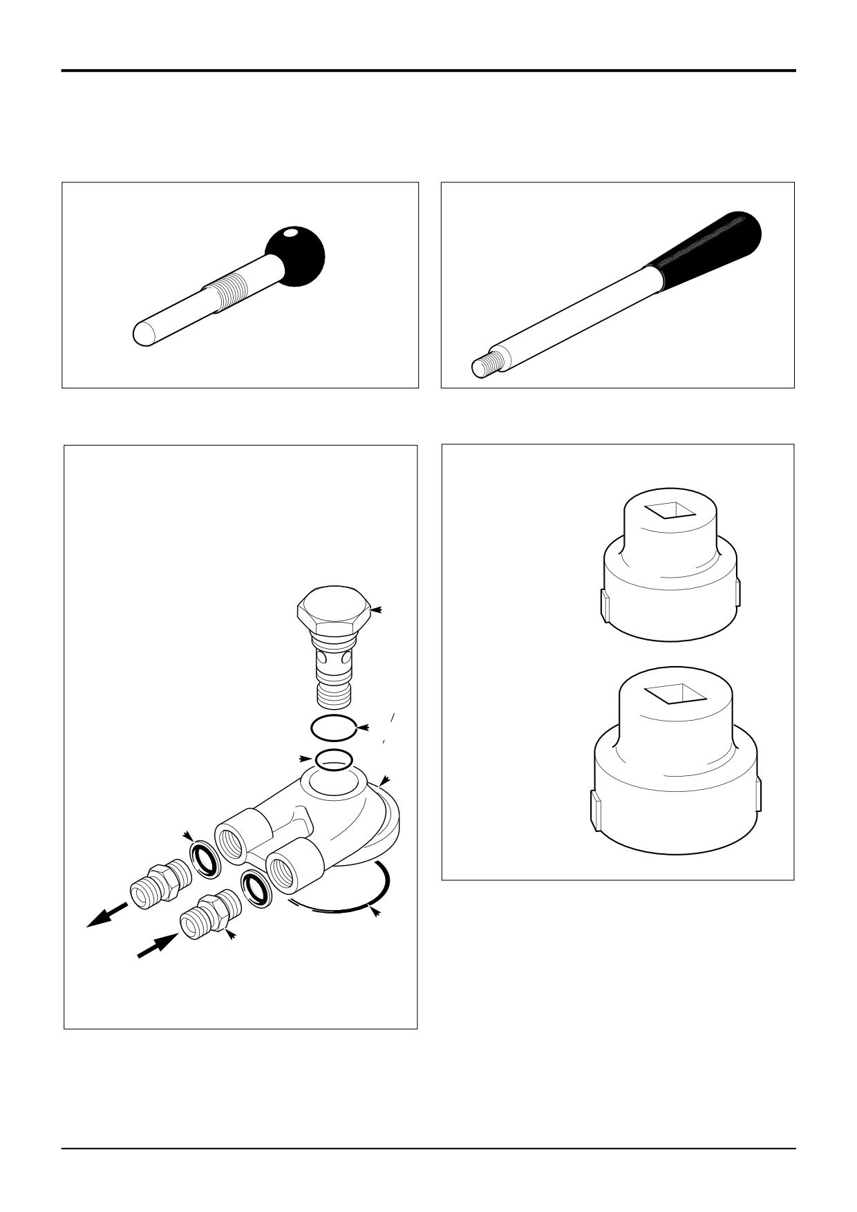
892/01077
Synchro Shuttle Gearbox - Selector
892/01078
Synchro Shuttle Gearbox - Mainshaft
Shaft Lock Screw
Adjuster
A395350
A396510
Synchro Shuttle Gearbox - Setting ring socket
spanners
Powershift Gearbox Flow Test Adaptor
892/01079
1
460/15708 Flow Test Adapter
(Mainshaft setting ring)
2
460/15707 Banjo Bolt
3
2401/0222 O-ring
4
2403/0110 O-ring
5
2403/0108 O-ring
6
1604/0004 Adapter
7
1406/0018 Sealing Washer
2
A396590
892/01080
(Layshaft setting ring)
4
5
1
7
A396600
3
6
A313250
9803/3280
Issue 1
Section 1
General Information
Section 1
4 - 14
4 - 14
Service Tools (cont'd)
Section F - Transmission
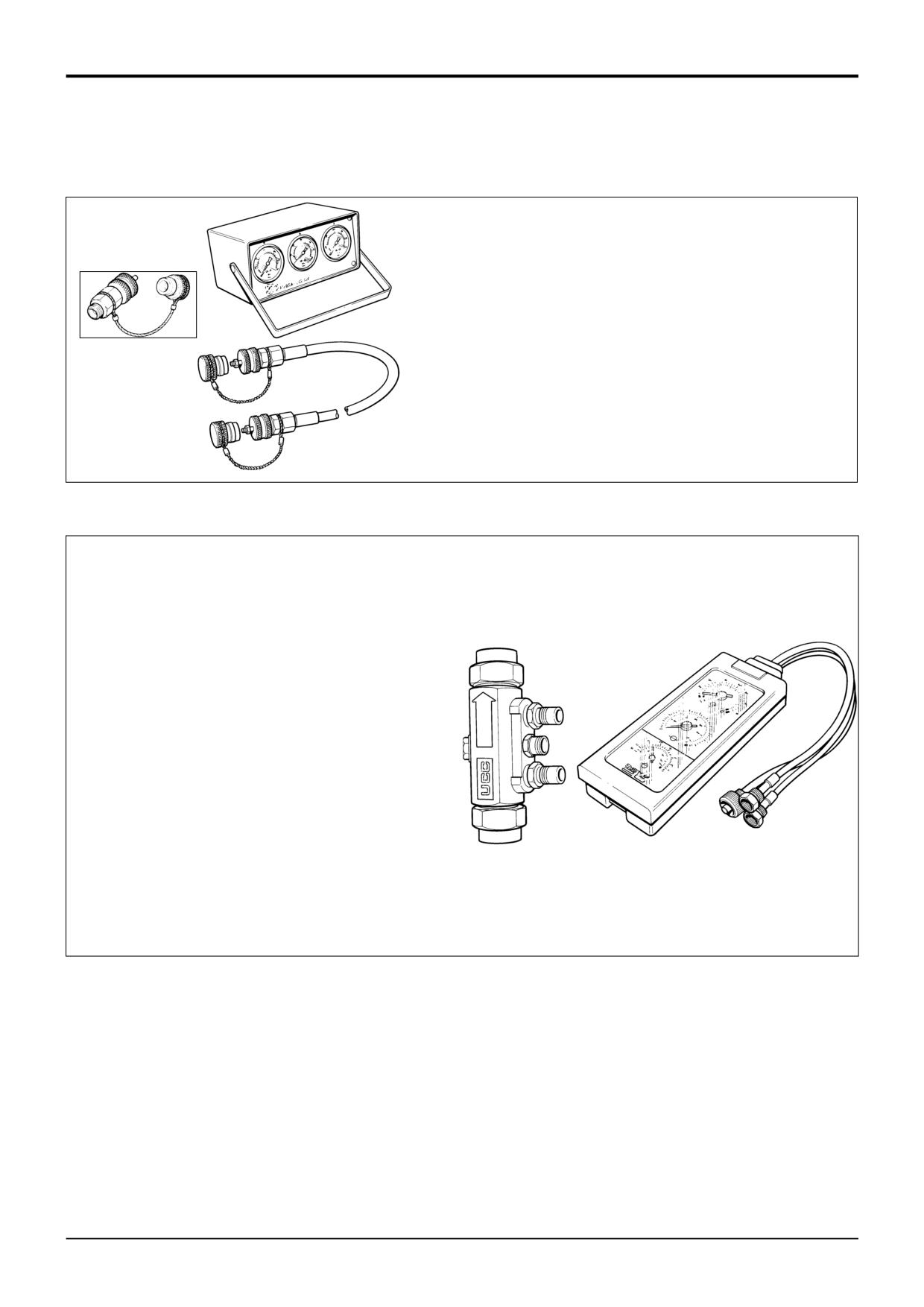
Hydraulic Circuit Pressure Test Kit (also used for main hydraulic
system tests)
892/00253
Pressure Test Kit
:892/00201
Replacement Gauge 0-20 bar (0-300 lbf/in2)
:892/00202
Replacement Gauge 0-40 bar (0-600 lbf/in2)
:892/00203
Replacement Gauge 0-400 bar (0-6000 lbf/in2)
S267300
:892/00254
Replacement Hose
993/69800
Seal Kit for 892/00254 (can also be used with
probe 892/00706)
892/00706
Test Probe
S188121
Flow Test Equipment (also used for main hydraulic system
tests)
892/00268
Flow Monitoring Unit
892/00269
Sensor Head 0 - 100 l/min (0 - 22 UK gal/min)
892/00293
Connector Pipe
892/00270
Load Valve
1406/0021
Bonded Washer
1604/0006
Adapter 3/4 in M x 3/4 in M BSP
1612/0006
Adapter 3/4 in F x 3/4 in M BSP
892/00271
Adapter 3/4 in F x 5/8 in M BSP
892/00272
Adapter 5/8 in F x 3/4 in M BSP
816/20008
Adapter 3/4 in F x 1/2 in M BSP
892/00275
Adapter 1/2 in F x 3/4 in M BSP
892/00276
Adapter 3/4 in F x 3/8 in M BSP
892/00277
Adapter 3/8 in F x 3/4 in M BSP
892/00273
Sensor Head 0 - 380 l/min
892/00294
Connector Pipe
1606/0015
Adapter 1.1/4 in M BSP x 1 in M BSP
892/00078
Connector 1 in F x 1 in F BSP
1604/0008
Adapter 1 in M x 1 in M BSP
S188151
1606/0012
Adapter 1 in M x 3/4 in M BSP
816/20013
Adapter 3/4 in F x 1 in M BSP
9803/3280
Issue 1
Section 1
General Information
Section 1
4 - 15
4 - 15
Service Tools (cont'd)
Section F - Transmission
1
5
A396960
6
6
A396930
3
7
A396950
4
A396940
8, 9
A396580
9803/3280
Issue 1
Section 1
General Information
Section 1
4 - 16
4 - 16
Service Tools (cont'd)
Section F - Transmission
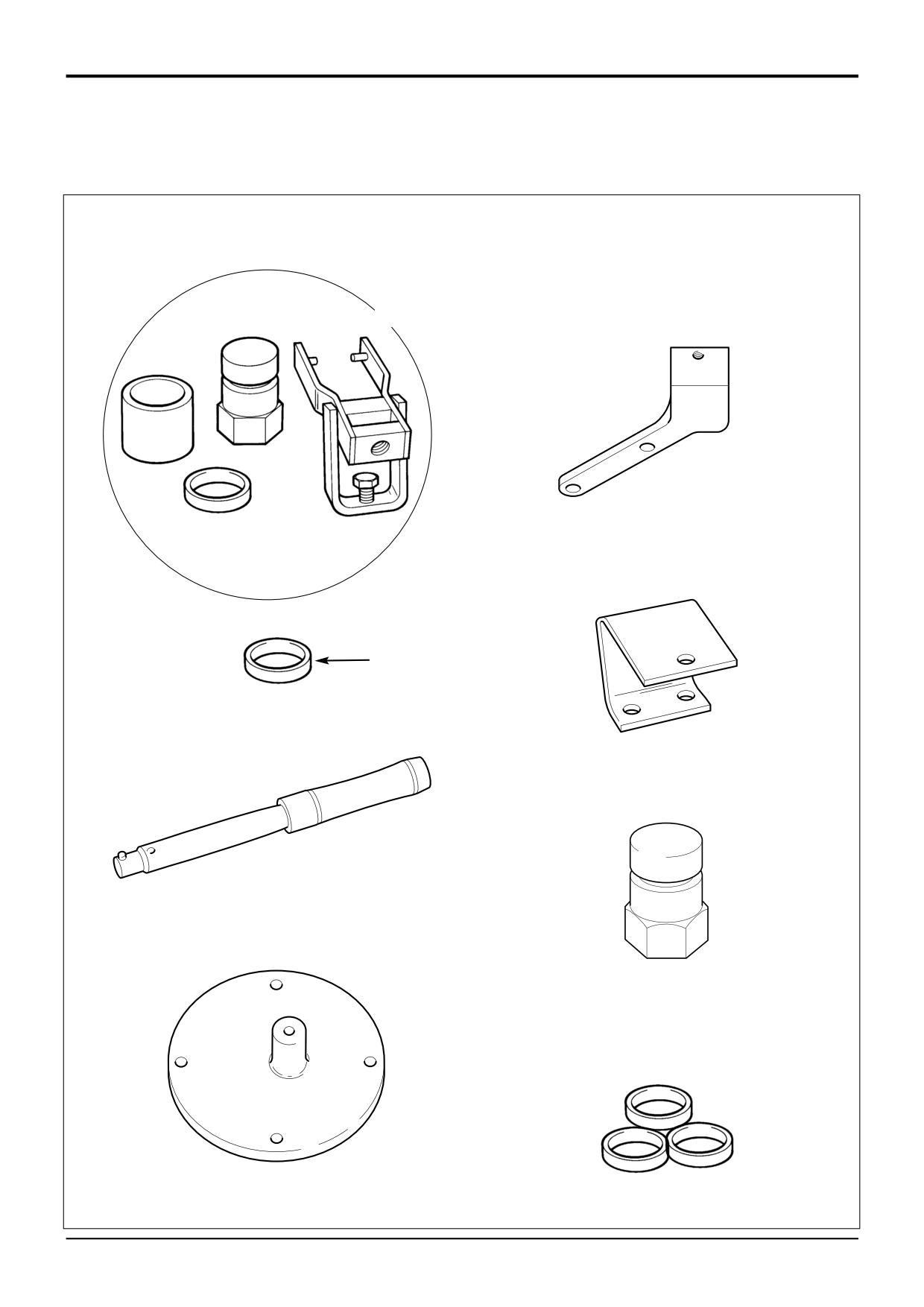
Solid Spacer Setting Kit
9
921/53400
Spacer Kit - Sychro Shuttle Gearbox,
Synchro Shuttle Gearbox, SD70, SD80
SD70, SD80 Axles
Axles
Comprises of:
1
892/00918
Setting Tool Kit
Spacer thickness mm
2
921/52627
Spacer 14.20 Service use
921/52628
12.600
3
993/70111
Breakback Torque Wrench
829/30405
12.625
4
892/01076
Support Bracket -
921/52629
12.650
829/30406
12.675
Synchro Shuttle Gearbox
921/52630
12.700
5
892/01075
Support Bracket
829/30407
12.725
PD70, SD80 Rear Axles
921/52601
12.750
6
997/11000
Support Bracket
829/30408
12.775
SD55, SD70 Front Axles
921/52602
12.800
7
998/10567
SD80 Pinion Shaft Adaptor
829/30409
12.825
921/52603
12.850
8
921/53300
Spacer Kit - SD55 Axles
829/30410
12.875
921/52604
12.900
Comprises of:
829/30411
12.925
Spacer thickness mm
921/52605
12.950
921/53322
13.550
829/30412
12.975
921/53323
13.575
921/52606
13.000
829/30413
13.025
921/53324
13.600
921/52607
13.050
921/53325
13.625
829/30414
13.075
921/53301
13.650
921/52608
13.100
921/53302
13.675
829/30415
13.125
921/53303
13.700
921/52609
13.150
921/53304
13.725
829/30416
13.175
921/53305
13.750
921/52610
13.200
921/53306
13.775
829/30417
13.225
921/53307
13.800
921/52611
13.250
921/53308
13.825
921/53424
13.275
921/53309
13.850
921/53425
13.300
921/53310
13.875
921/53426
13.325
921/53427
13.350
921/53311
13.900
921/53428
13.375
921/53312
13.925
921/53401
13.400
921/53313
13.950
921/53402
13.425
921/53314
13.975
921/53403
13.450
921/53315
14.000
921/53404
13.475
921/53316
14.025
921/53405
13.500
921/53317
14.050
921/53406
13.525
921/53318
14.075
921/53407
13.550
921/53319
14.100
921/53408
13.575
921/53320
14.125
921/53409
13.600
921/53321
14.150
921/53410
13.625
921/53411
13.650
921/53412
13.675
921/53413
13.700
921/53414
13.725
921/53415
13.750
921/53416
13.775
921/53417
13.800
921/53418
13.825
921/53419
13.850
921/53420
13.875
921/53421
13.900
921/53422
13.925
921/53423
13.950
921/52626
14.000
Note: After using a spacer, obtain a replacement to keep the
set complete.
9803/3280
Issue 1
Section 1
General Information
Section 1
4 - 17
4 - 17
Service Tools (cont'd)
Section F - Transmission
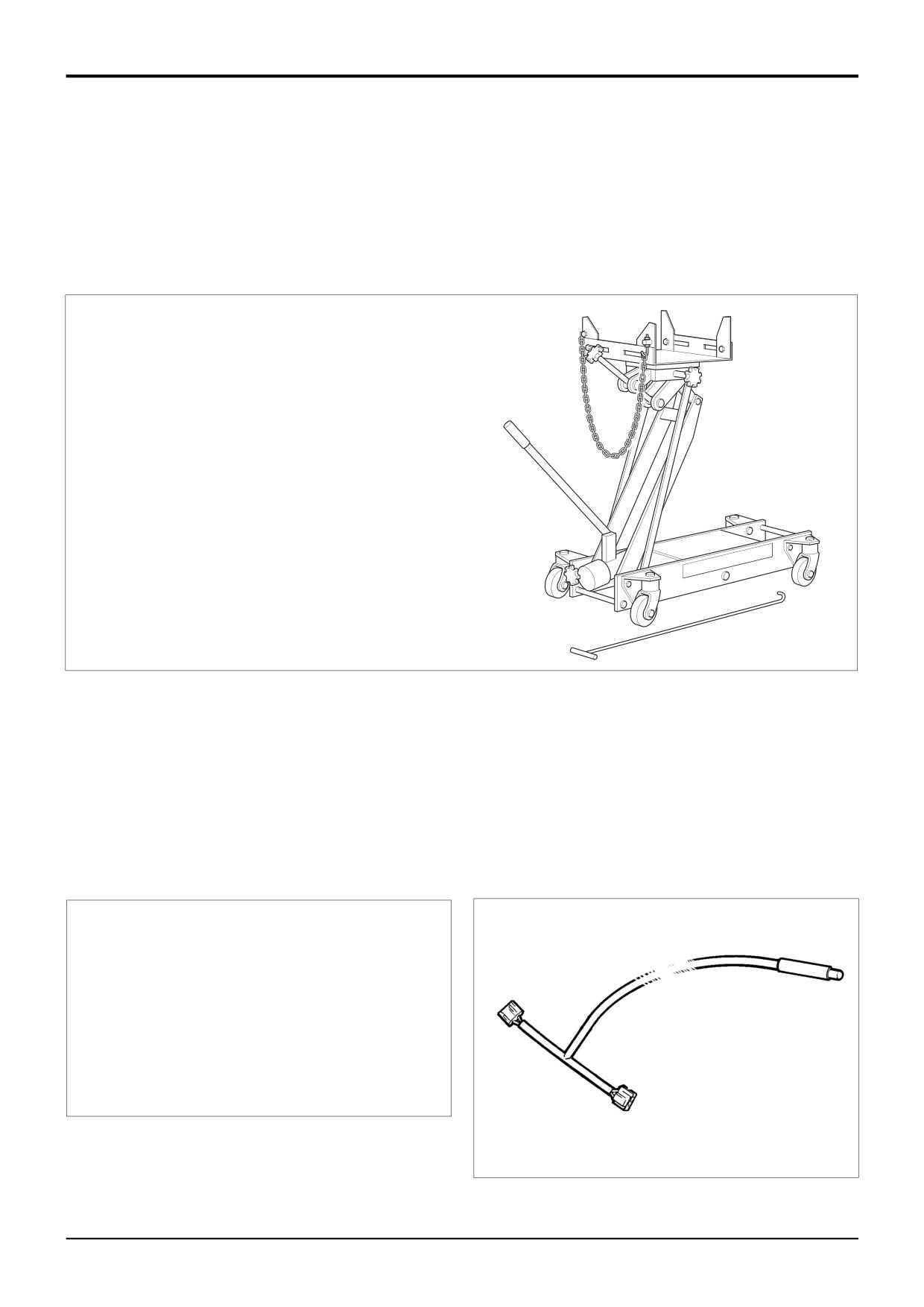
892/01083
Powershift - Assembly tool, transfer gear.
892/01084
Powershift - Transfer gear, bearing assembly.
892/01085
Powershift - Seal fitting tool
*
892/01094 Transmission Jack
When removing the Powershift gearbox use of a special
transmission jack is strongly recommended. This jack
can also be used when removing Synchro Shuttle
gearboxes.
Note that the jack must be used with special support
plates, see below.
A402680
* Powershift - Support plates, for use with transmission jack,
Manufacture locally, for details see Section F, Service
Tools.
892/01082 - Powershift - Assembly Cradle, for details see
Section F, Service Tools.
Powershift - Gearbox hydraulic pump removal tools, allow
*
pump to be removed with torque converter housing fitted to
gearbox. Manufacture locally, for details see Section F,
Service Tools.
*
*
823/10420
Thrust Washer Kit - Powershift
892/01096
Speed Sensor Test Harness -
gearbox - Layshaft clutch
Powershift Gearbox
Comprises of:
Washer thickness mm
823/10421
4.3
823/10422
4.4
823/10423
4.5
823/10424
4.6
823/10425
4.7
823/10426
4.8
298910
9803/3280
Issue 3*
Section 1
General Information
Section 1
4 - 18
4 - 18
Service Tools (cont'd)
Section F - Transmission
*
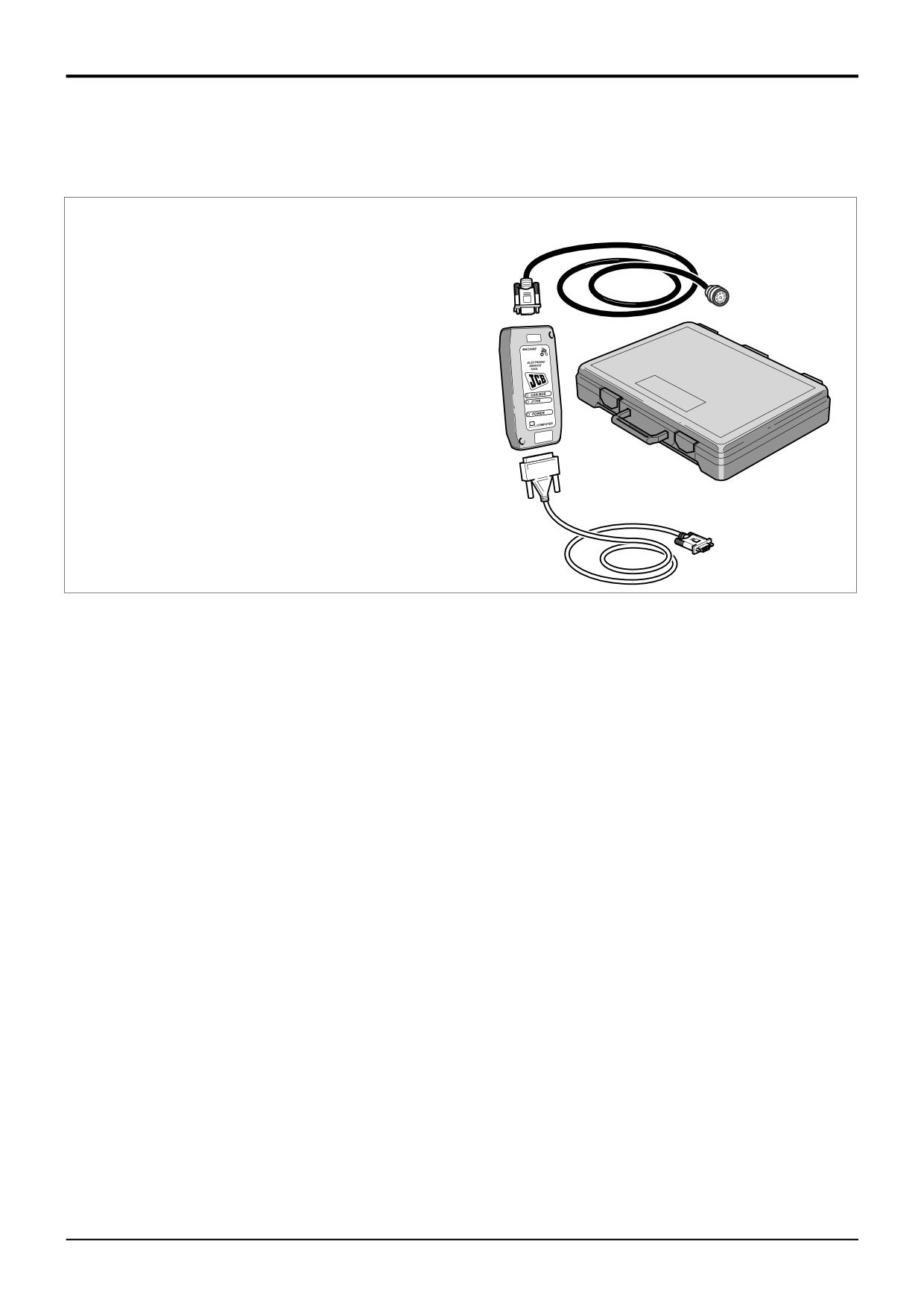
Powershift Gearbox - 6 Speed (ShiftMaster)
Electronic Service Tool Kit
3
892/01033 Kit comprises:
1
Data Link Adaptor (DLA), enables data exchange
between the machine ECU (Electronic Control Unit) and
1
a laptop PC loaded with the applicable ShiftMaster
diagnostics software.
4
2
Interconnecting cable, DLA to laptop PC. Several cables
are included to enable compatibility with different PC
port types.
3
Interconnecting cable, DLA to machine ECU diagnostics
socket.
4
Kit carrying case.
2
A406130
9803/3280
Issue 3*
Section 1
General Information
Section 1
4 - 19
4 - 19
Service Tools (cont'd)
Section K - Engine
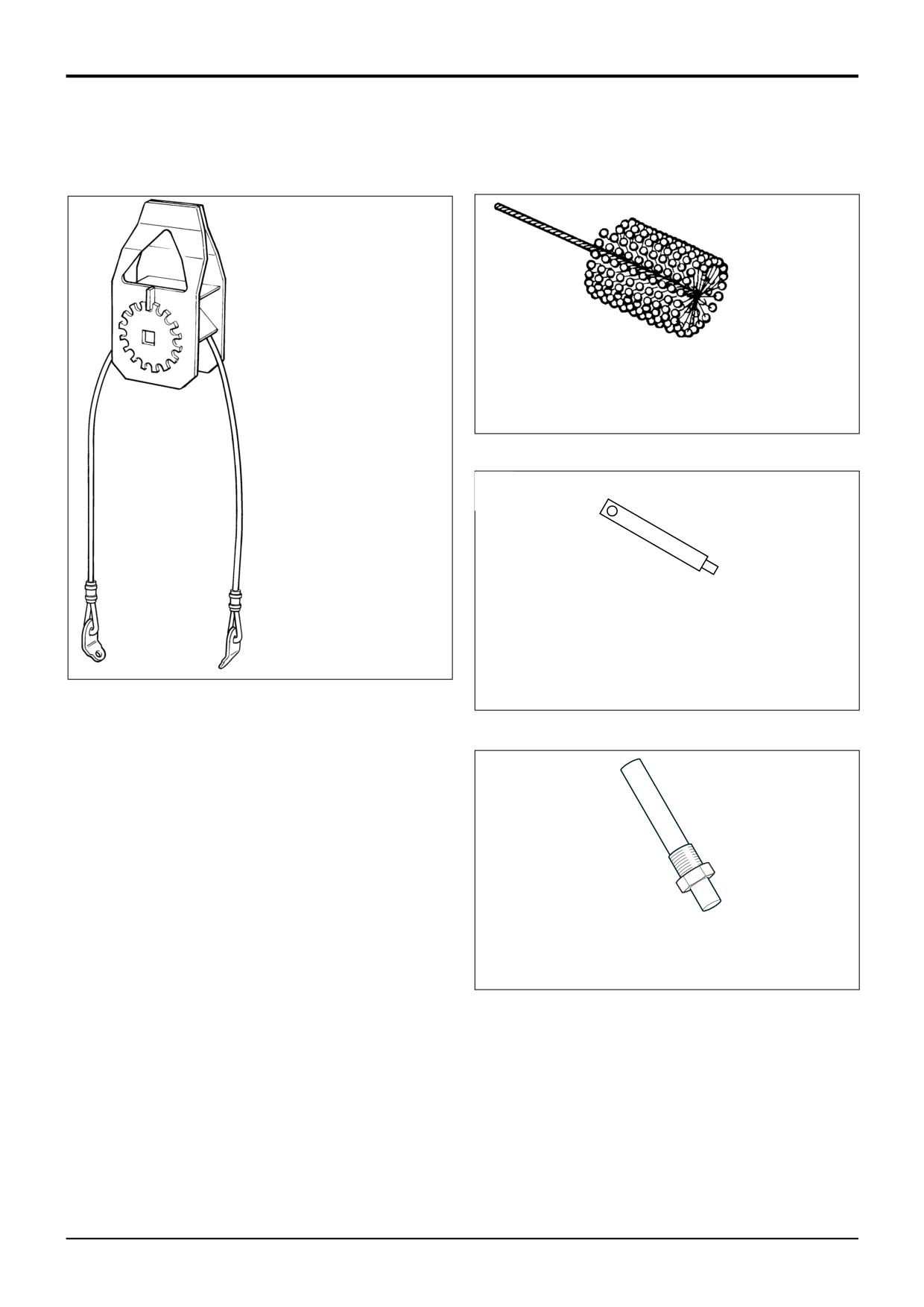
892/00836
Lifting Wire Assembly (for
engine removal)
S192390
S219080
892/00041
De-glazing Tool for Cylinder Bores (to
assist bedding-in of new piston rings)
A314530
892/00936
Timing pin for fuel injection pump
(AK, AM, AR)
892/0104
Adaptor for compression testing
(AK, AM, AR)
For details of other engine service tools refer to Engine
Service Manual, Publication No. 9806/0100 or 9806/2140 for
low emission engines.
9803/3280
Issue 1
Section 1
General Information
Section 1
5 - 1
5 - 1
Sealing and Retaining Compounds
JCB Multi-Gasket
A medium strength sealant suitable for all
sizes of gasket flanges, and for hydraulic fittings
of 25-65mm diameter.
4102/1212
50ml
JCB High Strength Threadlocker
A high strength locking fluid for use with threaded
components. Gasketing for all sizes of flange where
the strength of the joint is important.
4102/0551
50ml
JCB Retainer (High Strength)
For all retaining parts which are unlikely to be
dismantled.
4101/0651
50ml
JCB Threadlocker and Sealer
A high strength locking fluid for sealing
4101/0250
10ml
and retaining nuts, bolts, and screws up to
4101/0251
50ml
50mm diameter, and for hydraulic fittings up
to 25mm diameter.
Threadseal
A medium strength thread sealing compound.
4102/1951
50ml
Threadlocker
A locking fluid for use on threads larger than
50mm dia.
4101/0451
50ml
Activator
A cleaning primer which speeds the curing rate
4104/0251
(1ltr)
of anaerobic products.
4104/0253
Bottle (200ml)
Cleaner / Degreaser
For degreasing components prior to use of
anaerobic adhesives and sealants.
4104/1557
400ml
Direct Glazing Kit
For one pane of glass, comprises items
marked † below plus applicator nozzle etc.
993/55700
† Ultra Fast Adhesive
For direct glazing
4103/2109
310 ml
† Active Wipe 205
For direct glazing
4104/1206
30 ml
4104/1203
250 g
† Black Primer 206J
For direct glazing
4201/4906
30 ml
Clear Silicone Sealant
To seal butt jointed glass
4102/0933
Black Polyurethane Sealant
To finish exposed edges of laminated glass
4102/2309
310 ml
JCB Cleaner & Degreaser
For degreasing components prior to use of anaerobic
adhesives and sealants.
4104/1538
Aerosol
9803/3280
Issue 1
Section 2
Care & Safety
Section 2
i
i
Contents
Page No.
Safety Notices
1 - 1
General Safety
2 - 1
Operating Safety
3 - 1
Maintenance Safety
4 - 1
9803/3280
Issue 1
Section 2
Care & Safety
Section 2
1 - 1
1 - 1
Safety Notices
In this publication and on the machine, there are safety notices. Each notice starts with a
signal word. The signal word meanings are given below.
! DANGER
Denotes an extreme hazard exists. If proper precautions are not taken, it is highly
probable that the operator (or others) could be killed or seriously injured.
INT-1-2-1
! WARNING
Denotes a hazard exists. If proper precautions are not taken, the operator (or others)
could be killed or seriously injured.
INT-1-2-2
! CAUTION
Denotes a reminder of safety practices. Failure to follow these safety practices could
result in injury to the operator (or others) and possible damage to the machine.
INT-1-2-3
9803/3280
Issue 1
Section 2
Care & Safety
Section 2
2 - 1
2 - 1
All construction and agricultural equipment can be
hazardous. When a JCB machine is correctly operated and
properly maintained, it is a safe machine to work with. But
when it is carelessly operated or poorly maintained it can
become a danger to you (the operator) and others.
Do not work with the machine until you are sure that you can
control it.
Do not start any job until you are sure that you and those
around you will be safe.
If you are unsure of anything, about the machine or the job,
ask someone who knows. Do not assume anything.
Remember
BE CAREFUL
BE ALERT
BE SAFE
GEN-1-6
General Safety
! WARNING
! WARNING
Decals
Lifting Equipment
You can be injured if you do not obey the decal safety
You can be injured if you use faulty lifting equipment. Make
instructions. Keep decals clean. Replace unreadable or
sure that lifting equipment is in good condition. Make sure
missing decals with new ones before operating the machine.
that lifting tackle complies with all local regulations and is
Make sure replacement parts include warning decals where
suitable for the job. Make sure that lifting equipment is
necessary.
strong enough for the job.
INT-1-3-4
INT-1-3-7
! WARNING
! WARNING
Care and Alertness
Raised Attachments
All the time you are working with or on the machine, take
Raised attachments can fall and injure you. Do not walk or
care and stay alert. Always be careful. Always be alert for
work under raised attachments unless they are safely
hazards.
blocked.
INT-1-3-5
INT-1-3-8
! WARNING
Clothing
You can be injured if you do not wear the proper clothing.
Loose clothing can get caught in the machinery. Wear
protective clothing to suit the job. Examples of protective
clothing are: a hard hat, safety shoes, safety glasses, a well
fitting overall, ear-protectors and industrial gloves. Keep
cuffs fastened. Do not wear a necktie or scarf. Keep long
hair restrained.
INT-1-3-6
9803/3280
Issue 1
Section 2
Care & Safety
Section 2
3 - 1
3 - 1
Operating Safety
! WARNING
! WARNING
Machine Condition
ROPS/FOPS Structure
A defective machine can injure you or others. Do not operate
The machine is fitted with a Roll Over Protection Structure
a machine which is defective or has missing parts. Make
(ROPS) and a Falling Objects Protection Structure (FOPS).
sure the maintenance procedures in this handbook are
You could be killed or seriously injured if you operate the
completed before using the machine.
machine with a damaged or missing ROPS/FOPS. If the
INT-2-1-2
ROPS/FOPS has been in an accident, do not use the
machine until the structure has been renewed. Modifications
! WARNING
and repairs that are not approved by the manufacturer may
Controls
be dangerous and will invalidate the ROPS/FOPS
You or others can be killed or seriously injured if you operate
certification.
INT-2-1-9/3
the control levers from outside the cab. Operate the control
levers only when you are correctly seated inside the cab.
INT-2-1-3
! WARNING
Communications
! WARNING
Bad communications can cause accidents. Keep people
Machine Limits
around you informed of what you will be doing. If you will be
Operating the machine beyond its design limits can damage
working with other people, make sure any hand signals that
the machine, it can also be dangerous. Do not operate the
may be used are understood by everybody. Work sites can
machine outside its limits. Do not try to upgrade the
be noisy, do not rely on spoken commands.
INT-2-2-3
machine performance with unapproved modifications.
INT-2-1-4
! WARNING
! WARNING
Ramps and Trailers
Engine/Steering Failure
Water, mud, ice, grease and oil on ramps or trailers can
If the engine or steering fails, stop the machine as quickly as
cause serious accidents. Make sure ramps and trailers are
possible. Do not operate the machine until the fault has been
clean before driving onto them. Use extreme caution when
corrected.
driving onto ramps and trailers.
INT-2-1-5
INT-2-2-6
! WARNING
! DANGER
Engine
Sparks
The engine has exposed rotating parts. Do not open the
Explosions and fire can be caused by sparks from the
engine cover while the engine is running. Do not use the
exhaust or the electrical system. Do not use the machine in
machine with the cover open.
closed areas where there is flammable material, vapour or
INT-2-1-6/1
dust.
INT-2-2-10
! WARNING
Entering/Leaving
! WARNING
Always face the machine when entering and leaving the cab.
Powershift Transmission
Use the step(s) and handrails. Make sure the step(s),
Do not change from a high gear to a low gear (for instance,
handrails and your boot soles are clean and dry. Do not
4th to 1st) in one sudden movement whilst the machine is
jump from the machine. Do not use the machine controls as
moving. Otherwise the machine will rapidly decelerate, you
handholds, use the handrails.
or others could be killed or seriously injured. When selecting
INT-2-1-7
lower gears, allow the engine speed to drop before each
gear change.
! WARNING
2-1-1-9/1
Exhaust Gases
Breathing the machine exhaust gases can harm and
possibly kill you. Do not operate the machine in closed
spaces without making sure there is good ventilation. If
possible, fit an exhaust extension. If you begin to feel
drowsy, stop the machine at once. Get out of the cab into
fresh air.
INT-2-1-10
9803/3280
Issue 1
Section 2
Care & Safety
Section 2
4 - 1
4 - 1
Maintenance Safety
! WARNING
! WARNING
Battery
Repairs
A battery with frozen electrolyte can explode if it is used or
Do not try to do repairs or any other type of maintenance
charged. Do not use a machine with a frozen battery. To
work you do not understand. To avoid injury and/or damage
help prevent the battery from freezing, keep the battery fully
get the work done by a specialist engineer.
GEN-1-5
charged.
INT-3-1-7
! WARNING
! WARNING
Modifications and Welding
Battery Gases
Non-approved modifications can cause injury and damage.
Batteries give off explosive gases. Keep flames and sparks
Parts of the machine are made from cast iron; welds on cast
away from the battery. Do not smoke close to the battery.
iron can weaken the structure and break. Do not weld cast
Make sure there is good ventilation in closed areas where
iron. Contact your JCB distributor for advice before
batteries are being used or charged. Do not check the
modifying the machine.
INT-3-1-2/1
battery charge by shorting the terminals with metal; use a
hydrometer or voltmeter.
INT-3-1-8
! WARNING
Metal Splinters
! WARNING
You can be injured by flying metal splinters when driving
Battery Terminals
metal pins in or out. Use a soft faced hammer or drift to
The machine is negatively earthed. Always connect the
remove and fit metal pins. Always wear safety glasses.
INT-3-1-3
negative pole of the battery to earth.
When connecting the battery, connect the earth (-) lead last.
! WARNING
When disconnecting the battery, disconnect the earth (-)
Electrical Circuits
lead first.
Understand the electrical circuit before connecting or
INT-3-1-9
disconnecting an electrical component. A wrong connection
can cause injury and/or damage.
INT-3-1-4
! WARNING
Hydraulic Fluid
! WARNING
Fine jets of hydraulic fluid at high pressure can penetrate the
skin. Do not use your fingers to check for hydraulic fluid
Communications
leaks. Do not put your face close to suspected leaks. Hold a
Bad communications can cause accidents. If two or more
piece of cardboard close to suspected leaks and then
people are working on the machine, make sure each is
inspect the cardboard for signs of hydraulic fluid. If
aware of what the others are doing. Before starting the
hydraulic fluid penetrates your skin, get medical help
engine make sure the others are clear of the danger areas;
immediately.
examples of danger areas are: the rotating blades and belt
INT-3-1-10/1
on the engine, the attachments and linkages, and anywhere
beneath or behind the machine. People can be killed or
injured if these precautions are not taken.
INT-3-1-5
! DANGER
Hydraulic Pressure
Hydraulic fluid at system pressure can injure you. Before
! WARNING
disconnecting or connecting hydraulic hoses, stop the
Petrol
engine and operate the controls to release pressure trapped
Do not use petrol in this machine. Do not mix petrol with the
in the hoses. Make sure the engine cannot be started while
the hoses are open.
diesel fuel; in storage tanks the petrol will rise to the top and
INT-3-1-11/1
form flammable vapours.
INT-3-1-6
9803/3280
Issue 1
Section 2
Care & Safety
Section 2
4 - 2
4 - 2
Maintenance Safety (cont'd)
! CAUTION
! WARNING
Rams
Diesel Fuel
The efficiency of the rams will be affected if they are not
Diesel fuel is flammable; keep naked flames away from the
kept free of solidified dirt. Clean dirt from around the rams
machine. Do not smoke while refuelling the machine or
regularly. When leaving or parking the machine, close all
working on the engine. Do not refuel with the engine
rams if possible to reduce the risk of weather corrosion.
running. There could be a fire and injury if you do not follow
INT-3-2-10
these precautions.
INT-3-2-2
! CAUTION
! WARNING
Cleaning
Cleaning metal parts with incorrect solvents can cause
Oil
corrosion. Use only recommended cleaning agents and
Oil is toxic. If you swallow any oil, do not induce vomiting,
solvents.
seek medical advice. Used engine oil contains harmful
INT-3-2-11
contaminants which can cause skin cancer. Do not handle
used engine oil more than necessary. Always use barrier
cream or wear gloves to prevent skin contact. Wash skin
! CAUTION
contaminated with oil thoroughly in warm soapy water. Do
not use petrol, diesel fuel or paraffin to clean your skin.
'O' rings, Seals and Gaskets
INT-3-2-3
Badly fitted, damaged or rotted 'O' rings, seals and gaskets
can cause leakages and possible accidents. Renew
whenever disturbed unless otherwise instructed. Do not use
! WARNING
Triochloroethane or paint thinners near 'O' rings and seals.
INT-3-2-12
Soft Ground
A machine can sink into soft ground. Never work under a
machine on soft ground.
! WARNING
INT-3-2-4
Fires
If your machine is equipped with a fire extinguisher, make
! WARNING
sure it is checked regularly. Keep it in the operator's cab
until you need to use it.
Tyres and Rims
Over-inflated or over-heated tyres can explode. Follow the
Do not use water to put out a machine fire, you could
instructions in this handbook for inflating the tyres. Do not
spread an oil fire or get a shock from an elecrical fire. Use
weld or cut rims. Get a tyre/wheel specialist to do any repair
carbon dioxide, dry chemical or foam extinguishers. Contact
work.
INT-3-2-6
your nearest fire department as quickly as possible.
Firefighters should use self-contained breathing apparatus.
INT-3-2-7/1
! WARNING
Hot Coolant
! WARNING
The cooling system is pressurised when the engine is hot.
Jacking
Hot coolant can spray out when you remove the radiator
A machine can roll off jacks and crush you unless the
cap. Let the system cool before removing the radiator cap.
wheels have been chocked. Always chock the wheels at the
To remove the cap; turn it to the first notch and let the
opposite end of the machine that is to be jacked. Do not
system pressure escape, then remove the cap.
INT-3-2-9
work underneath a machine supported only by jacks.
Always support a jacked-up machine on axle stands before
working underneath it.
INT-3-2-8
! WARNING
Always wear safety glasses when dismantling assemblies
containing components under pressure from springs. This
will protect against eye injury from components accidently
flying out.
GEN 6-2
9803/3280
Issue 1
Section 2
Care & Safety
Section 2
4 - 3
4 - 3
Maintenance Safety (cont'd)
! WARNING
! WARNING
To avoid burning, wear protective gloves when handling hot
Hydraulic Hoses
components. To protect your eyes, wear goggles when
Damaged hoses can cause fatal accidents. Inspect the
using a wire brush to clean components.
hoses regularly for:
HYD 1-3
-
Damaged end fittings
-
Chafed outer covers
-
Ballooned outer covers
! WARNING
-
Kinked or crushed hoses
-
Embedded armouring in outer covers
JCB Extradig Dipper Lubricant
-
Displaced end fittings.
JCB Extradig dipper lubricant contains 1.53% lead. The
INT-3-3-2
repeated swallowing of very small quantities can cause
chronic lead poisoning. Do not smoke or touch food while
handling this lubricant. Dispose of waste (rags etc.) in
! WARNING
accordance with local regulations.
2-1-1-8
Safety Strut
Raised loader arms can drop suddenly and cause serious
injury. Before working under raised loader arms, fit the
! WARNING
loader arm safety strut.
2-1-1-6
Fluoroelastomeric Materials
Certain seals and gaskets (e.g. crankshaft oil seal) on JCB
machines contain fluoroelastomeric materials such as Viton,
! WARNING
Fluorel and Technoflon. Fluoroelastomeric materials
subjected to high temperatures can produce highly
A raised and badly supported machine can fall on you.
corrosive hydrofluoric acid. THIS ACID CAN SEVERELY
Position the machine on a firm, level surface before raising
BURN.
one end. Ensure the other end is securely chocked. Do not
rely solely on the machine hydraulics or jacks to support the
New fluoroelastomeric components at ambient temperature
machine when working under it.
require no special safety precautions.
Disconnect the battery, to prevent the engine being started
Used fluoroelastomeric components whose temperatures
while you are beneath the machine.
GEN-1-1
have not exceeded
300°C require no special safety
precautions. If evidence of decomposition (e.g. charring) is
found, refer to the next paragraph for safety instructions DO
! WARNING
NOT TOUCH COMPONENT OR SURROUNDING AREA.
Waxoyl contains turpentine substitute, which is flammable.
Used fluoroelastomeric components subjected to
Keep flames away when applying Waxoyl. Waxoyl can take
temperatures greater than 300°C (e.g. engine fire) must be
a few weeks to dry completely. Keep flames away during the
treated using the following safety procedure. Make sure that
drying period.
heavy duty gloves and special safety glasses are worn:
Do not weld near the affected area during the drying period.
1
Ensure that components have cooled then remove and
Take the same precautions as for oil to keep Waxoyl off your
place material into plastic bags.
skin. Do not breathe the fumes. Apply in a well-ventilated
area.
5-3-1-9
2
Thoroughly wash contaminated area with 10% calcium
hydroxide or other suitable alkali solution, if necessary
use wire wool to remove burnt remains.
! WARNING
3
Thoroughly wash contaminated area with detergent
Make the machine safe before working underneath it. Park
and water.
the machine on level ground, lower the arms. Apply the
parking brake, put the transmission in neutral and stop the
4
Contain all removed material, gloves etc. used in this
engine. Chock both sides of all four wheels.
operation in sealed plastic bags and dispose of in
accordance with Local Authority Regulations.
Disconnect the battery, to prevent the engine being started
while you are beneath the machine.
DO NOT BURN FLUOROELASTOMERIC MATERIALS.
GEN-1-2
If contamination of skin or eyes occurs, wash the affected
area with a continuous supply of clean water or with calcium
hydroxide solution for 15-60 minutes. Get medical attention
immediately.
INT-3-3-5/1
9803/3280
Issue 1
Section 3
Routine Maintenance
Section 3
i
i
Contents
Page No.
Lubricants - Health and Safety
Hygiene
2 - 1
Storage
2 - 1
Handling
2 - 1
First Aid - Oil
2 - 1
Spillage
2 - 1
Fires
2 - 1
Service Schedules
3 - 1
Loader Arm Safety Strut
Installing and Removing
4 - 1
Checking for Damage
5 - 1
Cleaning the Machine
6 - 1
Engine Panels
Opening and Closing the Bonnet
7 - 1
Removing and Fitting a Side Panel
7 - 1
Seat Belt
Checking the Seat Belt Condition and Security
8 - 1
Greasing
General
9 - 1
Loader Arms
9 - 1
Backhoe Quickhitch
9 - 2
Front Axle (2 Wheel Drive Machines)
9 - 3
Front Axle (4 Wheel Drive Machines)
9 - 3
Front Axle (All Wheel Steer Machines)
9 - 4
Rear Axle (All Wheel Steer Machines)
9 - 4
Extending Dipper
9 - 5
Driveshafts
9 - 5
6 - in - 1 Clamshovel
9 - 6
Stabilisers (Centremount Machines)
9 - 6
Loader Quickhitch
9 - 6
Power Sideshift
9 - 7
Kingpost
9 - 7
Knuckle (if fitted)
9 - 8
Backhoe Quickhitch (Hydraulic)
9 - 8
Tyres and Wheels
Tyre Inflation
10 - 1
Checking the Wheel Nut Torques
10 - 1
Brakes
Parking Brake Adjustment
11 - 1
Checking the Foot Brake Fluid Level
11 - 1
Engine Air Filter
Changing the Elements
12 - 1
9803/3280
Issue 1
Section 3
Routine Maintenance
Section 3
ii
ii
Contents
Page No.
Engine Oil and Filter
Checking the Oil Level
13 - 1
Changing the Oil and Filter
13 - 1
Engine Cooling System
Checking the Coolant
14 - 1
*
Changing the Coolant
14 - 1
Adjusting the Fan Belt
14 - 2
*
Cleaning the Cab Heater Filter
14 - 2
*
Fuel System
Types of Fuel
15 - 1
Fuel Standards
15 - 1
Low Temperature Fuels
15 - 1
Fatty Acid Methyl Ester Fuels
15 - 1
Petrol
15 - 1
Advice
15 - 1
Filling the Tank
15 - 2
Draining the Filter
15 - 2
Changing the Filter Element
15 - 2
Draining the Sediment Bowl
15 - 3
Bleed the System
15 - 3
Synchro Shuttle Gearbox
Checking the Oil Level
16 - 1
Changing the Oil and Filter
16 - 1
Powershift Gearbox
Checking the Oil Level
17 - 1
Changing the Oil Filter
17 - 2
*
Hydraulic System
Checking the Fluid Level
18 - 1
Hydraulic Tank Cap
18 - 1
Changing the Filter Element
18 - 2
Changing the Suction Strainer
18 - 3
Front and Rear Axle (All Wheel Steer Machines)
Checking the Differential Oil Level
19 - 1
Changing the Differential Oil
19 - 1
Checking the Hub Oil Levels
19 - 2
Changing the Hub Oil
19 - 2
Front and Rear Axle (Two Wheel Steer Machines)
Checking the Oil Level
19 - 3
Changing the Oil
19 - 3
Battery
Warning Symbols
21 - 1
First Aid - Electrolyte
21 - 2
Checking the Electrolyte Level
21 - 2
Battery Isolator
21 - 3
9803/3280
Issue 2*
Section 3
Routine Maintenance
Section 3
iii
iii
Contents
Page No.
Hydraulic Oil Cooler
Cleaning the Tubes/Fins
23 - 1
Stabiliser Legs
Wear Pads
25 - 1
Wear Pad Adjustment
25 - 1
Air Conditioning
Adjusting the Compressor Drive Belt
26 - 1
Hose Burst Protection Valve (if fitted)
Checking Hose Burst Protection Valve
27 - 1
Lowering a Load
27 - 1
Service Capacities and Lubricants
28 - 1
Coolant Mixtures
28 - 2
9803/3280
Issue 1
Section 3
Routine Maintenance
Section 3
2 - 1
Lubricants - Health and Safety
2 - 1
It is most important that you read and understand this
2
Apply a barrier cream to the skin before handling used
information and the publications referred to. Make sure
oil.
all your colleagues who are concerned with lubricants
read it too.
3
Note the following when removing engine oil from skin:
Hygiene
a Wash your skin thoroughly with soap and water.
b Using a nail brush will help.
JCB lubricants are not a health risk when used properly for
their intended purposes.
c Use special hand cleansers to help clean dirty
hands.
However, excessive or prolonged skin contact can remove
the natural fats from your skin, causing dryness and
d Never use petrol, diesel fuel, or paraffin for washing.
irritation.
4
Avoid skin contact with oil soaked clothing.
Low viscosity oils are more likely to do this, so take special
care when handling used oils, which might be diluted with
5
Don't keep oily rags in pockets.
fuel contamination.
6
Wash dirty clothing before re-use.
Whenever you are handling oil products you should maintain
good standards of care and personal and plant hygiene. For
7
Throw away oil-soaked shoes.
details of these precautions we advise you to read the
relevant publications issued by your local health authority,
plus the following.
First Aid - Oil
Storage
Eyes.
In the case of eye contact, flush with water for 15 minutes. If
irritation persists, get medical attention.
Always keep lubricants out of the reach of children.
Swallowing.
Never store lubricants in open or unlabelled containers.
If oil is swallowed do not induce vomiting. Get medical
advice.
Waste Disposal
Skin.
All waste products should be disposed of in accordance
In the case of excessive skin contact, wash with soap and
with all the relevant regulations.
water.
The collection and disposal of used oil should be in
Spillage
accordance with any local regulations. Never pour used
engine oil into sewers, drains or on the ground.
Absorb on sand or a locally approved brand of absorbent
granules. Scrape up and remove to a chemical disposal
Handling
area.
New Oil.
Fires
There are no special precautions needed for the handling or
Extinguish with carbon dioxide, dry chemical or foam. Fire-
use of new oil, beside the normal care and hygiene
fighters should use self-contained breathing apparatus.
practices.
Used Oil.
Used engine crankcase lubricants contain harmful
contaminants.
Here are precautions to protect your health when handling
used engine oil:
1
Avoid prolonged, excessive or repeated skin contact
with used oil.
9803/3280
Issue 1
Section 3
Routine Maintenance
Section 3
3 - 1
Service Schedules
3 - 1
A badly maintained machine is a danger to the operator and
Apart from the daily jobs, the schedules are based on
the people working around him. Make sure that the regular
machine running hours. Keep a regular check on the
maintenance and lubrication jobs listed in the service
hourmeter readings to correctly gauge service intervals. Do
schedules are done to keep the machine in a safe and
not use a machine which is due for a service. Make sure
efficient working condition.
any defects found during the regular maintenance checks
are rectified immediately.
! WARNING
Calendar equivalents:
Maintenance
10 Hours
=
Daily
Maintenance must be done by suitably qualified
50 Hours
=
Weekly
personnel. Before attempting any maintenance work,
500 Hours
=
Six Months
make sure the machine is safe. Park on level ground. If it
1000 Hours
=
Yearly
is necessary to work with the loader arms raised, then
2000 Hours
=
2 Years
the loader arm safety strut must be fitted as shown in
Loader Arm Safety Strut in MAINTENANCE section.
2-3-1-1
Pre-start Cold Checks
Operation
10
50
†100
500
1000
2000
Service Points and Fluid Levels
Hr
Hr
Hr
Hr
Hr
Hr
ENGINE
Oil level
- Check
!
!
Oil and Filter "
- Change
!
!
!
!
Air Cleaner Outer Element #
- Change
!
!
Air Cleaner Inner Element
- Change
!
Fuel Filter
- Change
!
!
!
!
Fuel Filter
- Drain
!
Coolant Quality/Level
- Check
!
!
!
!
!
!
Fuel Sedimenter
- Drain and Clean
!
!
!
!
!
Fan Belt Tension/Condition
- Check
!
!
!
!
!
Valve Clearances and Clean Breather Gauze (if fitted) $
- Check and Adjust
!
Engine Mounting Bolts for Tightness $
- Check
!
!
!
!
Radiator
- Clean
!
!
!
All Hoses - Condition
- Check
!
!
!
!
TRANSMISSION, AXLES
AND STEERING
Transmission Oil Level
- Check
!
!
!
!
Transmission Oil %
- Change
!
!
Transmission Filter
- Change
!
!
!
!
Axle Oil Level (incl. Hubs when applicable) &
- Check
!
!
Axle Oil (incl. Hubs when applicable) '
- Change
!
!
Axle Oil - Limited Slip Differential
- Change
!
!
!
Tyre Pressures/Condition
- Check
!
!
!
!
!
!
Front Hub Bearings $
- Check
!
!
!
!
Transmission Strainer
- Clean
!
!
Drive Shafts
- Security/Grease
!
!
!
!
Steer Axle Movement/Shimming $
- Check
!
!
!
!
Steer Axle Pivots and Linkages (
- Grease
!
!
!
!
Front Axle Main Pivot
- Grease
!
!
!
!
!
!
HYDRAULICS
Oil Level )
- Check
!
!
!
!
!
Oil $
- Sample/Change
!
Oil Filter
- Change
!
!
!
!
Rams - Chrome Condition
- Check
!
!
!
!
9803/3280
Issue 1
Section 3
Routine Maintenance
Section 3
3 - 2
Service Schedules
3 - 2
Pre-start Cold Checks
Operation
10
50
†100
500
1000
2000
Service Points and Fluid Levels
Hr
Hr
Hr
Hr
Hr
Hr
Hydraulic Oil Cooler
- Clean
!
!
!
Hydraulic Oil Strainer
- Clean
!
Hydraulic Tank Filler Cap (with integral filter)
- Change
!
Hydraulic Pump Drive Shaft
- Examine/Grease
!
!
!
!
BRAKES
Brake System Fluid Level
- Check
!
!
!
!
!
!
Brake System Fluid $
- Change
!
Parking Brake
- Check and Adjust
!
!
!
!
ELECTRICS
Battery Electrolyte Level (if applicable)
- Check
!
!
!
Wiring for Chaffing/Routing
- Check
!
!
!
!
!
Battery Terminals for Condition and Tightness
- Check
!
!
!
!
BODYWORK AND CAB
All Pins and Bushes
- Check and Grease
!
!
!
!
!
!
Door/Window Hinges
- Lubricate
!
!
!
All Cables
- Lubricate
!
!
!
Cab Heater Filter #
- Clean/Change
!
!
!
Extending Dipper
- Adjust/Grease
!
!
!
!
!
Hydraclamp $
- Check and Adjust
!
!
!
!
Door - Fit and Catches
- Check
!
!
!
!
Cab Seat - Operation
- Check
!
!
!
!
Front Mudguards - Security (if fitted)
- Check
!
!
Windscreen Washer Fluid Level
- Check
!
!
!
!
!
!
Boom Lock Engagement
- Check
!
!
!
!
!
!
Condition of Paintwork
- Check
!
!
!
!
Stabiliser Legs (Sideshift)
- Check/Adjust
!
!
!
!
!
Machine Generally $
- Check and Clean
!
!
!
!
!
!
Power Sideshift Wear Pads
- Grease
!
!
!
!
!
!
Power Sideshift Wear Pads
- Check
!
!
Power Sideshift Chain
- Lubricate
!
!
!
!
!
Power Sideshift Chain Tension
- Check/Adjust
!
!
!
!
ATTACHMENTS
6-in-1 Clam Shovel
- Grease
!
!
!
!
!
!
Backhoe & Loader Quick Hitch
- Grease
!
!
!
!
!
!
Functional Test
Operation
10
50
†100
500
1000
2000
and Final Inspection
Hr
Hr
Hr
Hr
Hr
Hr
ENGINE
Idle Speed $
- Check and Adjust
!
!
!
!
Stall Speed $
- Check
!
!
!
!
Maximum No-Load Speed $
- Check and Adjust
!
!
!
!
Exhaust Smoke (excessive)
- Check
!
!
!
!
!
Exhaust System Security $
- Check
!
!
!
!
Air Inlet System Security
- Check
!
!
!
!
Throttle System and Control Cable $
- Check
!
!
!
!
TRANSMISSION, AXLES AND STEERING
Steer Modes - Operation/Phasing
- Check
!
!
!
!
!
!
2WD/4WD Selection
- Check
!
!
!
!
Wheel Nuts Torque
- Check
!
!
!
!
!
!
Forward/Reverse and Gear Change - Operation
- Check
!
!
!
!
9803/3280
Issue 1
Section 3
Routine Maintenance
Section 3
3 - 3
Service Schedules
3 - 3
Functional Test
Operation
10
50
†100
500
1000
2000
and Final Inspection
Hr
Hr
Hr
Hr
Hr
Hr
Hydraulic Speed Control - Operation (if fitted)
- Check
!
!
!
!
Steer Circuit Pressure $
- Check
!
!
!
!
Transmission Main Line Pressure $
- Check
!
!
!
Transmission Dump Operation
- Check
!
!
!
!
Neutral Start Operation
- Check
!
!
!
!
!
Clutch Pack Pressures $
- Check
!
!
!
!
HYDRAULICS
MRV Pressure $
- Check and Adjust
!
!
!
!
Operation All Services
- Check
!
!
!
!
!
Hose Burst Protection Valves (if fitted)
- Check
!
!
!
!
Offloader Valve Pressure $
- Check and Adjust
!
!
!
!
Auxiliary Circuit & Pressures $
- Check and Adjust
!
!
!
!
BRAKES
Foot Brake - Operation
- Check
!
!
!
!
!
!
Parking Brake - Operation
- Check
!
!
!
!
!
!
Servo Operation (if fitted)
- Check
!
!
!
!
ELECTRICS
Starter Motor
- Check
!
!
!
!
Alternator - Output
- Check
!
!
!
!
All Electrical Equipment Operation, (e.g. warning lights, beacon,
- Check
!
!
!
!
!
!
alarms, horn, wipers etc)
Operation of Stop Control/E.S.O.S.
- Check
!
!
!
!
!
!
BODYWORK AND CAB
Teeth and Side Cutters
- Check
!
!
!
!
Doors and Windows - Fitment/Leaks
- Check
!
!
!
!
Seat/Seat Belts
- Check
!
!
!
!
† Note: First 100 Hours Service only, to be completed by your JCB Distributor.
& Note: Check for leaks every 50 hours, check level if leaking.
) Note: Check the hydraulic fluid level with the loader and backhoe in the travel position.
$ Note: Jobs which should only be done by a specialist are indicated by a † .
" Note: If operating under arduous conditions, change the engine oil and filter every 250 hours.
* Note: Check generally for leaks on ALL systems, for example, hydraulic, engine (coolant, fuel and oil), transmission,
brakes, axles etc. If a leak is evident find the source and repair as required. Make sure that the system is topped up with
the recommended fluid after repair. Examples of machine general damage are paintwork, toe plate, glazing rubbers etc.,
repair any damage as required. If any of the repair or top up procedures are not detailed in this handbook, then contact
your local JCB Distributor for advice.
# Note: If operating in dusty working environments, change more frequently.
( Note: The axles and driveshafts are factory greased with a high performance grease, if during service a standard grease is
used, then the interval must be reduced to every 50 hours, contact your JCB Distributor for advice.
% Note: After a major transmission repair, the new oil should be run to operating temperature and changed again to remove
any contamination which entered during the repair. Change the oil and filter after a further 100 hours if the oil was heavily
contaminated because of, or from the failure (eg. water contamination).
' Note: After a hub repair, the new oil should be run to operating temperature and changed again to remove any
contamination which entered during the repair. Change the oil again after a further 100 hours to remove any bedding-in
wear. This is particularly important if new brake plates have been fitted.
9803/3280
Issue 1
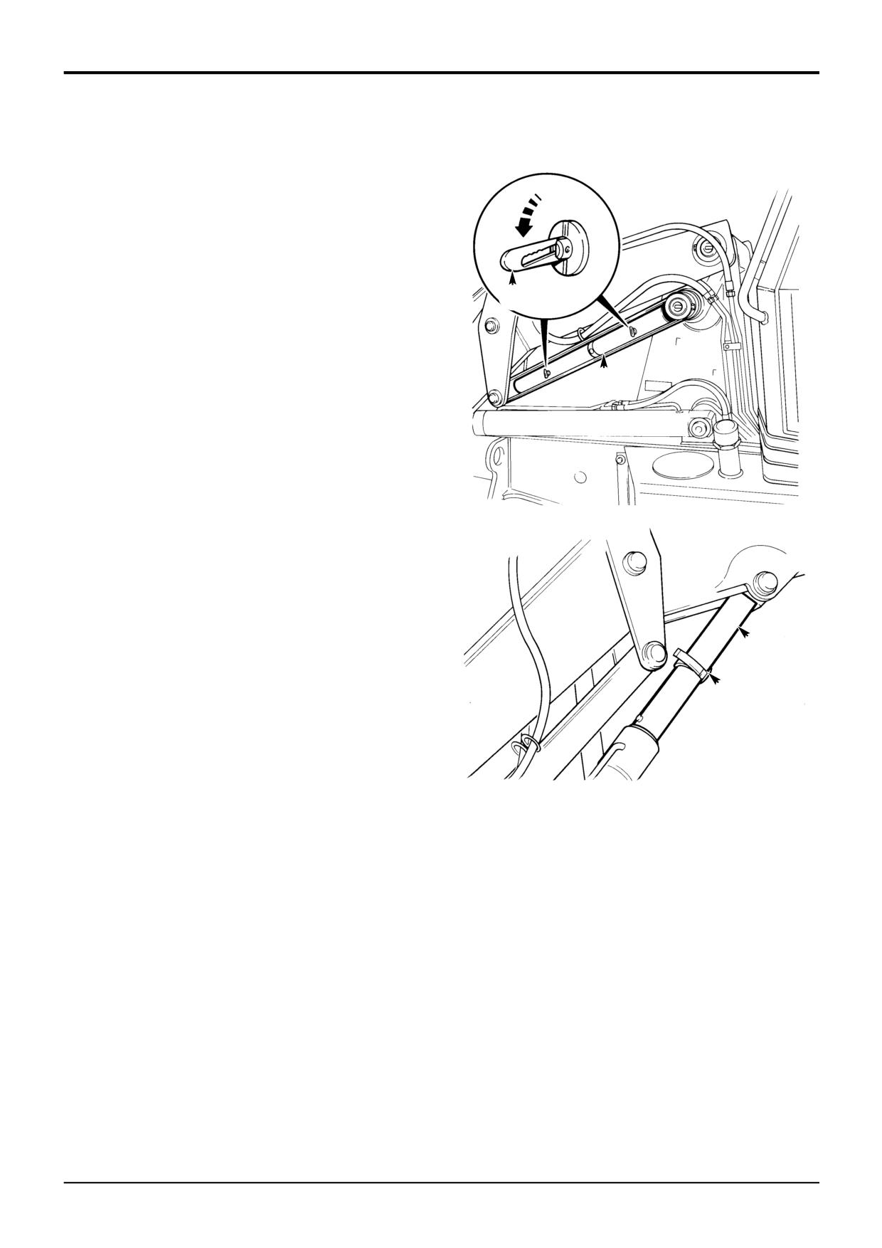
Section 3
Routine Maintenance
Section 3
4 - 1
Loader Arm Safety Strut
4 - 1
Installing
Install the loader arm safety strut as detailed below before
working underneath raised loader arms.
! WARNING
Raised loader arms can drop suddenly and cause
serious injury. Before working under raised loader arms,
fit the loader arm safety strut.
2-1-1-6
A
1
Empty the Shovel and Raise the Loader Arms fully.
2
Stop the Engine
Remove the starter key.
C
! WARNING
You could be killed or injured if the loader control is
accidentally operated. Make sure no-one comes near
the machine while you release the safety strut.
2-3-1-2
S215110
3
Release the Strut
a Release fastener A.
b Remove strut C from its stowage bracket.
4
Install the Strut
a Push strut C over the ram piston rod.
b Secure the strut in position with strap B.
5
Lower the Strut Onto the Cylinder
To prevent any chance of the loader arms creeping
C
down and trapping your fingers, the loader arms should
be carefully lowered onto the safety strut as shown.
B
Start the engine and slowly lower the loader arms onto
the safety strut, stop the movement immediately the
weight of the loader arms is supported by the safety
strut.
S161710
Note: When lowering the loader, operate the control lever
carefully. 'Feather' the lever to lower the loader very slowly.
Removing
1
Fully Raise the Loader Arms
To take the weight off the safety strut.
2
Stop the Engine
Remove the starter key.
! WARNING
You could be killed or injured if the loader control is
accidentally operated. Make sure no one comes near the
machine while you remove the safety strut.
2-3-1-3
3
Remove the Strut
a Undo the strap B.
b Remove the strut C from the ram piston rod.
4
Stow the Strut
Secure the strut in its stowage position with fastener A.
9803/3280
Issue 1
Section 3
Routine Maintenance
Section 3
5 - 1
Checking for Damage
5 - 1
Inspect steelwork for damage. Note damaged paintwork for
future repair.
Make sure all pivot pins are correctly in place and secured
by their locking devices.
Ensure that the steps and handrails are undamaged and
secure.
Check for broken or cracked window glass. Replace
damaged items.
Check all bucket teeth for damage and security.
Check all lamp lenses for damage.
Inspect the tyres for damage and penetration by sharp
objects.
Check that all safety decals are in place and undamaged. Fit
new decals where necessary.
9803/3280
Issue 1
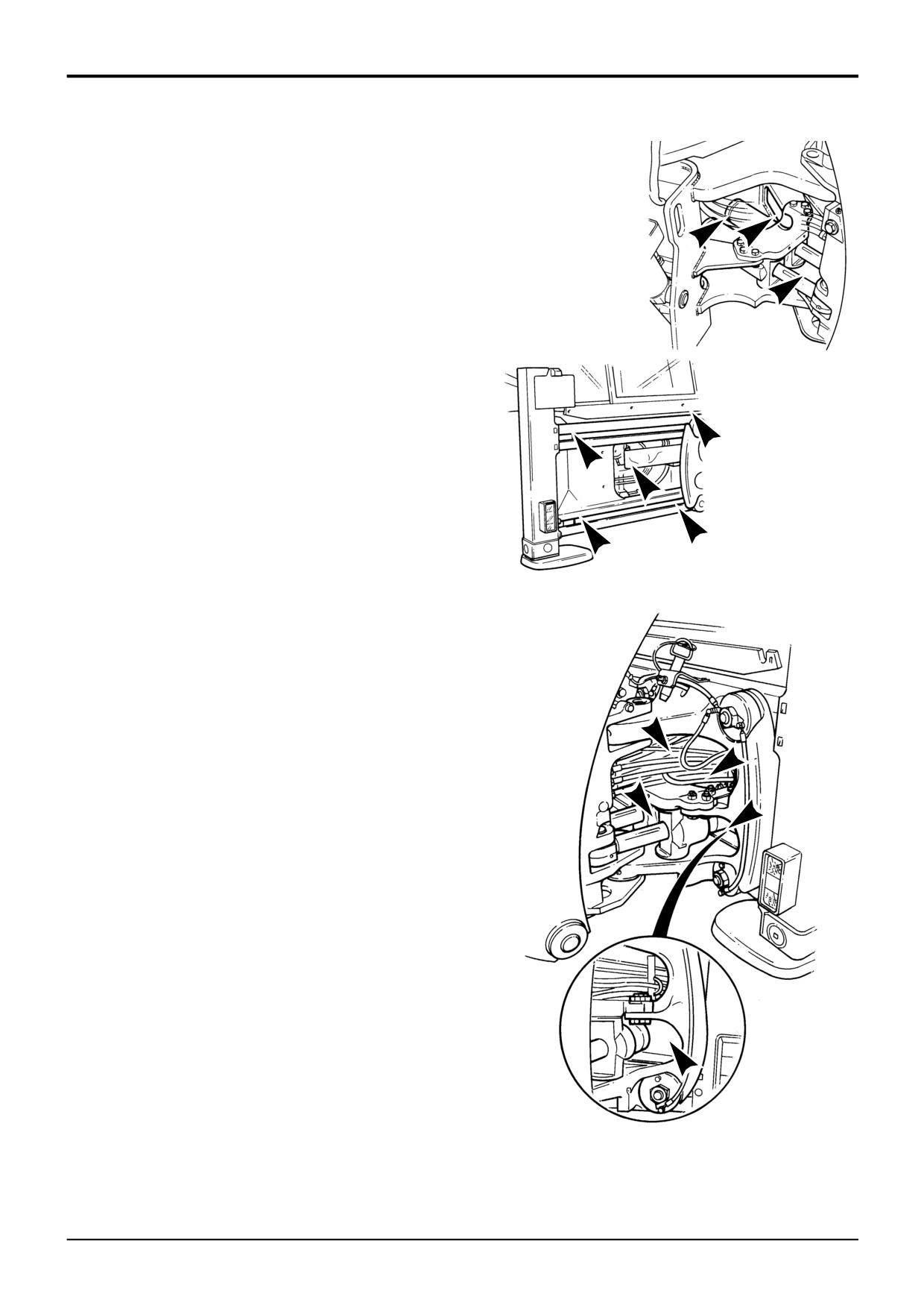
Section 3
Routine Maintenance
Section 3
6 - 1
Cleaning the Machine
6 - 1
Park the machine on firm level ground, engage the parking
brake and set the transmission to neutral. Lower the
attachments to the ground and stop the engine.
Clean the machine using water and/or steam. Do not allow
mud, debris etc to build upon the machine, pay particular
attention to the following areas:
1
Backhoe hoses passing through mainframe.
2
Around twin slew rams.
3
Twin ram slew recess in chassis (centremount).
4
Kingpost slide rails (sideshift).
5
Kingpost hose tray and bottom ‘shelf’ (sideshift).
6
Recess between slew ram and kingpost casting
S272900
(sideshift).
Stabiliser cavities can become clogged when operating in
soft/wet ground conditions. Remove and clean away all
debris that may have built up.
Do not allow mud to build up on the engine and
transmission. Make sure the radiator grille is not clogged up.
! WARNING
Airborne particles of light combustible material such as
straw, grass, wood shavings, etc. must not be allowed to
S272880
accumulate within the engine compartment or in the
propshaft guards (when fitted). Please inspect these
areas frequently and clean at the beginning of each work
shift or more often if required. Before opening the engine
cover, ensure that the top is clear of debris.
5-3-1-12/2
Avoid using neat detergent - always dilute detergents as per
the manufacturer's recommendations, otherwise damage to
the paint finish may occur.
It is important to note that excessive power washing can
cause damage to the seals or bearings. Take care during
routine machine washing not to direct high power water jets
directly at oil seals or universal joints.
Note: The machine must always be greased after pressure
washing or steam cleaning.
Always adhere to local regulations regarding the disposal of
debris created from machine cleaning.
The illustrations show some of the areas that must be
thoroughly cleaned as required.
S272890
9803/3280
Issue 1
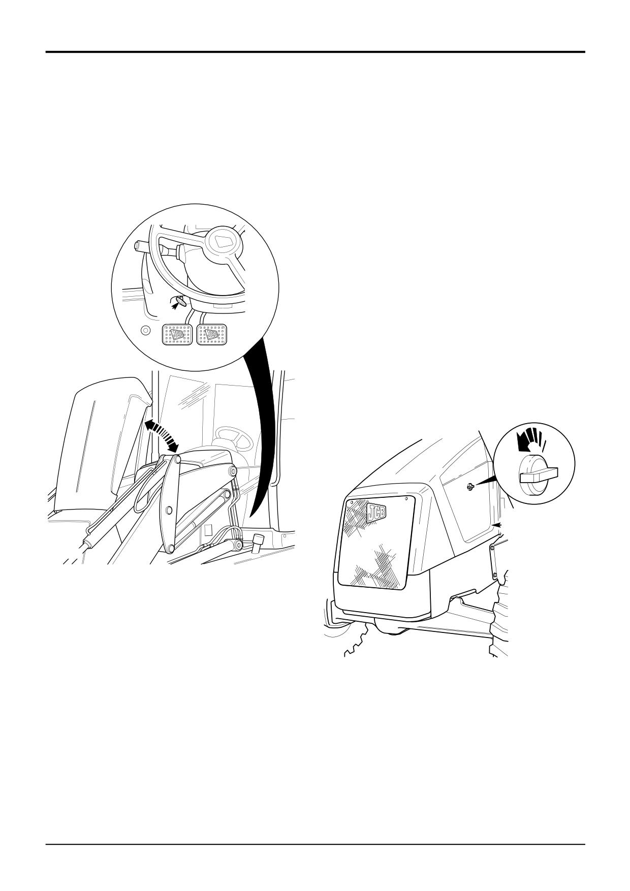
Section 3
Routine Maintenance
Section 3
7 - 1
Engine Panels
7 - 1
Opening and Closing the Bonnet
Removing and Fitting a Side Panel
To release the bonnet, pull handle A, the bonnet will
! WARNING
automatically open and be supported on gas struts.
The loader arms must be raised and locked before you
remove an engine side panel. Keep the arms locked up
To close the bonnet, push the bonnet down, make sure it is
until the side panel is put back. If you do not lock the
locked in place and the side panels are located correctly.
loader arms, the shovel can fall and you could be
crushed. See Loader Arm Safety Strut in MAINTENANCE
section.
2-3-1-4/1
! WARNING
Do not remove the engine side panel while the engine is
running.
2-3-1-5
1
Raise the loader arms and fit the safety strut, see
Loader Arms Safety Strut.
2
Stop the engine, and remove the starter key.
A
3
Open the bonnet.
4
Remove the side panel B, lift the side upwards and
outwards.
5
Fit the side panel, carefully slot the side panel into
position. Lower and lock the bonnet.
B
399110
399380
9803/3280
Issue 1
Section 3
Routine Maintenance
Section 3
8 - 1
Seat Belt
8 - 1
Checking the Seat Belt Condition and
Security
! WARNING
When a seat belt is fitted to your machine replace it with
a new one if it is damaged, if the fabric is worn, or if the
machine has been in an accident. Fit a new seat belt
every three years.
2-3-1-7/1
Inspect the seat belt for signs of fraying and stretching.
Check that the stitching is not loose or damaged. Check that
the buckle assembly is undamaged and works correctly.
Check that the belt mounting bolts are undamaged,
correctly fitted and tightened.
9803/3280
Issue 1
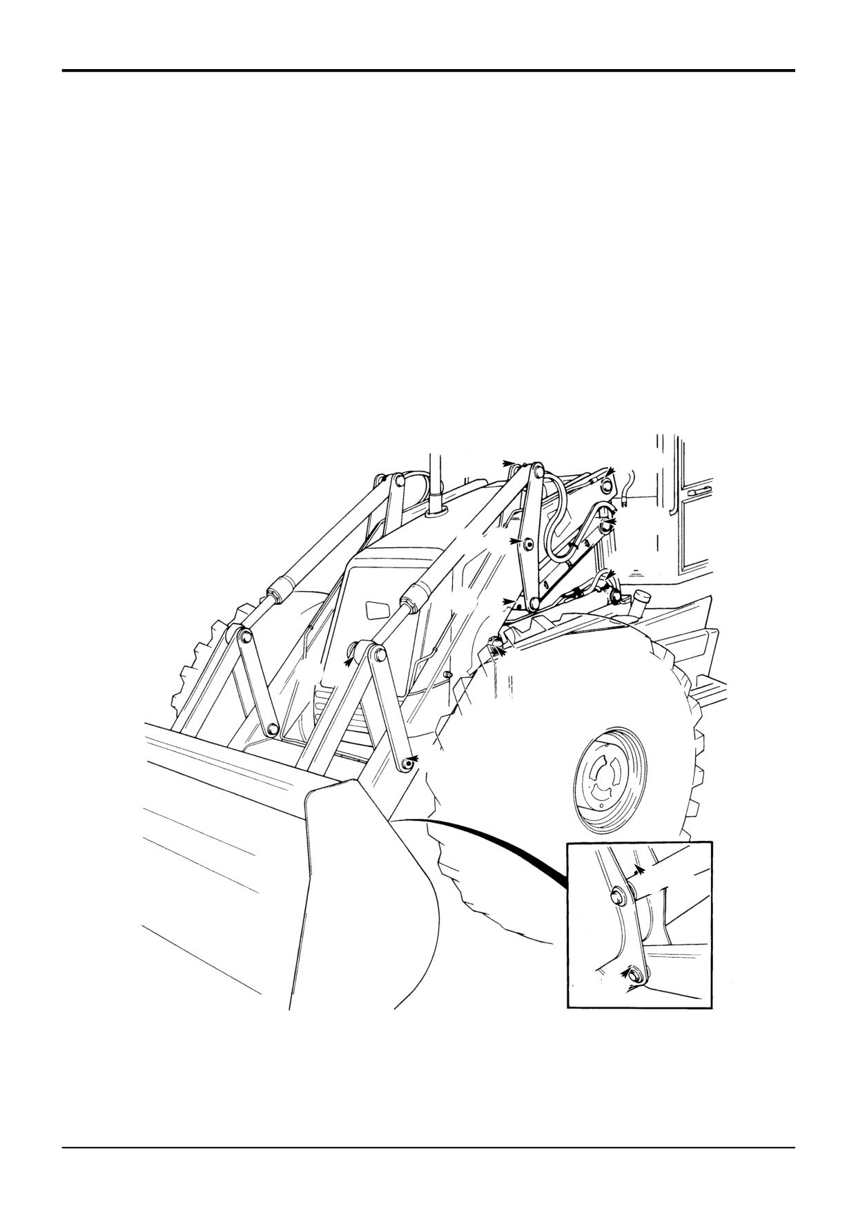
Section 3
Routine Maintenance
Section 3
9 - 1
Greasing
9 - 1
You must grease the machine regularly to keep it working
Greasing should be done with a grease gun. Normally, two
efficiently. Regular greasing will also lengthen the machine's
strokes of the gun should be sufficient. Stop greasing when
working life.
fresh grease appears at the joint.
The machine must always be greased after pressure
In the following illustrations, the grease points are
washing or steam cleaning.
numbered. Count off the grease points as you grease each
one. Refit the dust caps after greasing.
! WARNING
You will be working close into the machine for these
Loader Arms
jobs. Lower the attachments if possible. Remove the
starter key and disconnect the battery. This will prevent
For each grease point shown, there is another on the other
the engine being started. Make sure the parking brake is
side of the machine.
engaged.
Total 22 grease points.
Chock all four wheels before getting under the machine.
2-3-2-1
3
4
12
56
78
90
!@
£$
%
^
&*
()
¤⁄
S260190
9803/3280
Issue 1
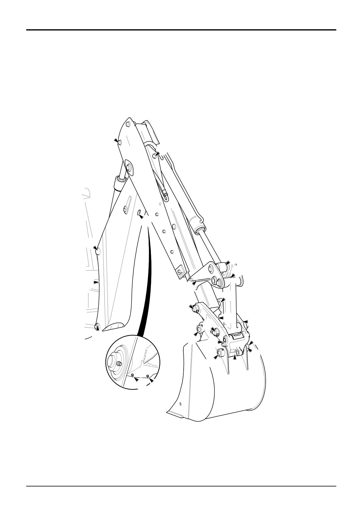
Section 3
Routine Maintenance
Section 3
9 - 2
Greasing
9 - 2
Backhoe & Quickhitch
22 Grease Points
Note: Figure shows a typical boom and dipper arrangement.
^
%
&
*
$
£
(
@
8
7
6
0
9
)
4
5
!
3
1 2
⁄¤
A340900
9803/3280
Issue 1
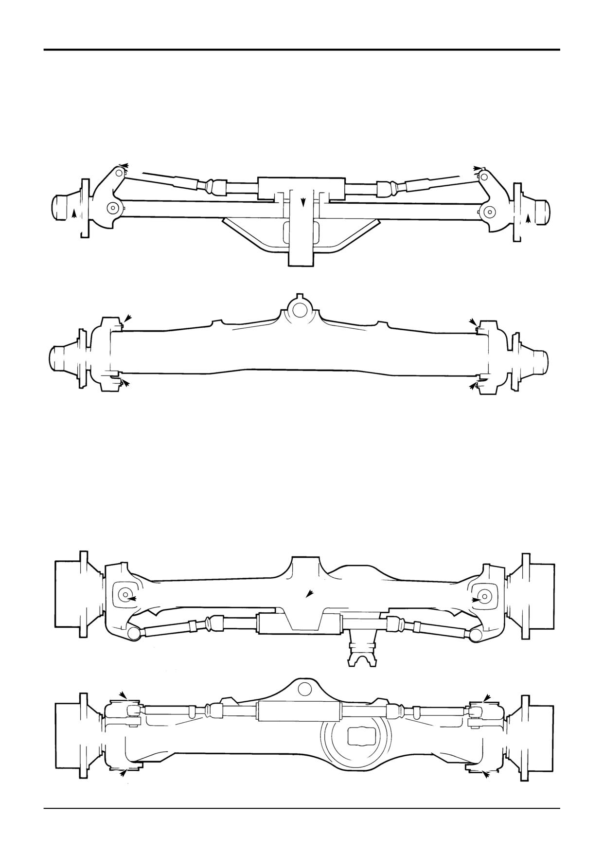
Section 3
Routine Maintenance
Section 3
9 - 3
Greasing
9 - 3
Front Axle (2 Wheel Drive Machines)
9 Grease Points
Note: Grease point 5 is a remote grease point mounted on
the side of the mainframe chassis (near the left front wheel).
3
4
5
1
2
6
8
7
9
S260200
Front Axle (4 Wheel Drive Machines)
5 Grease Points
Note: Grease point 5 is a remote grease point mounted on
the side of the mainframe chassis (near the left front wheel).
5
12
4
3
1
3
2
4
S260210
9803/3280
Issue 1
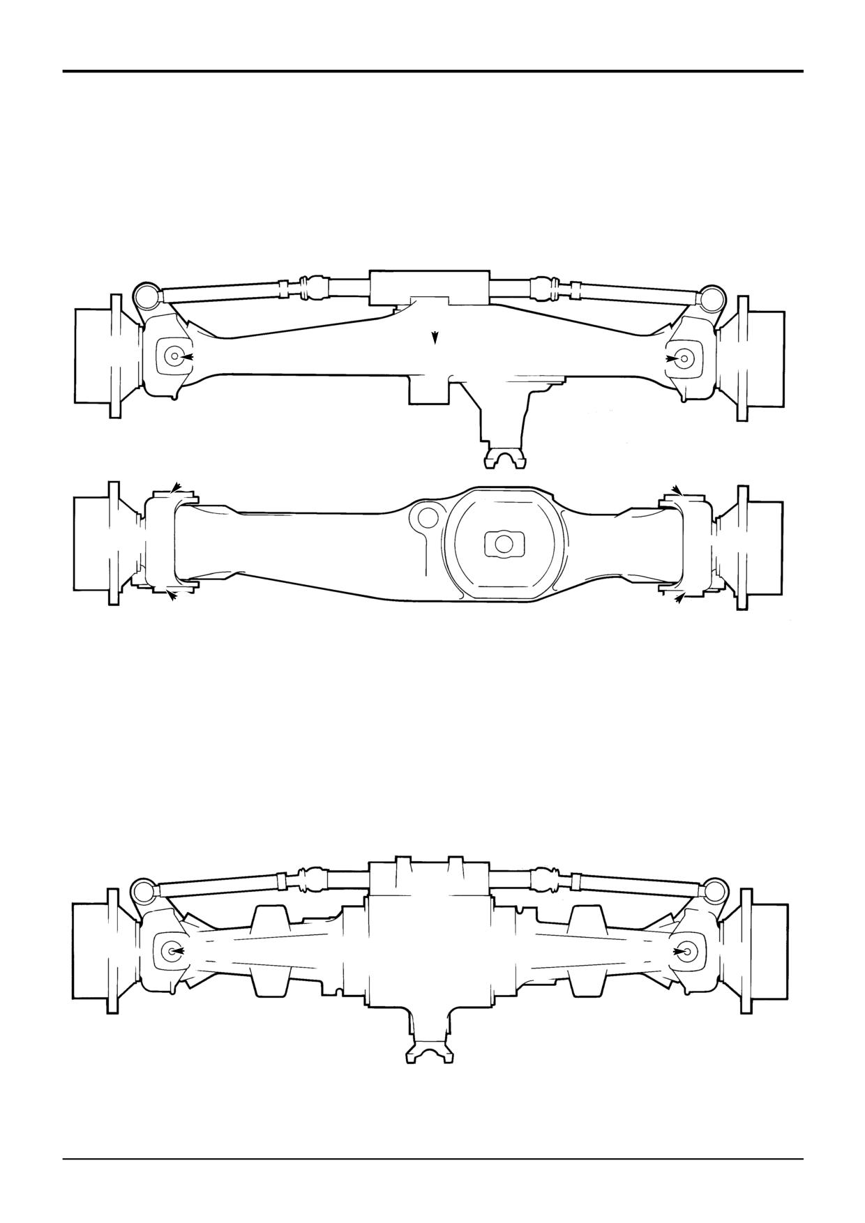
Section 3
Routine Maintenance
Section 3
9 - 4
Greasing
9 - 4
Front Axle (All Wheel Steer Machines)
5 Grease Points
Note: Grease point 5 is a remote grease point mounted on
the side of the front nose (near the left front wheel).
5
12
3
4
1
3
2
S260220
4
Rear Axle (All Wheel Steer Machines)
4 Grease Points
12
34
S260230
9803/3280
Issue 1
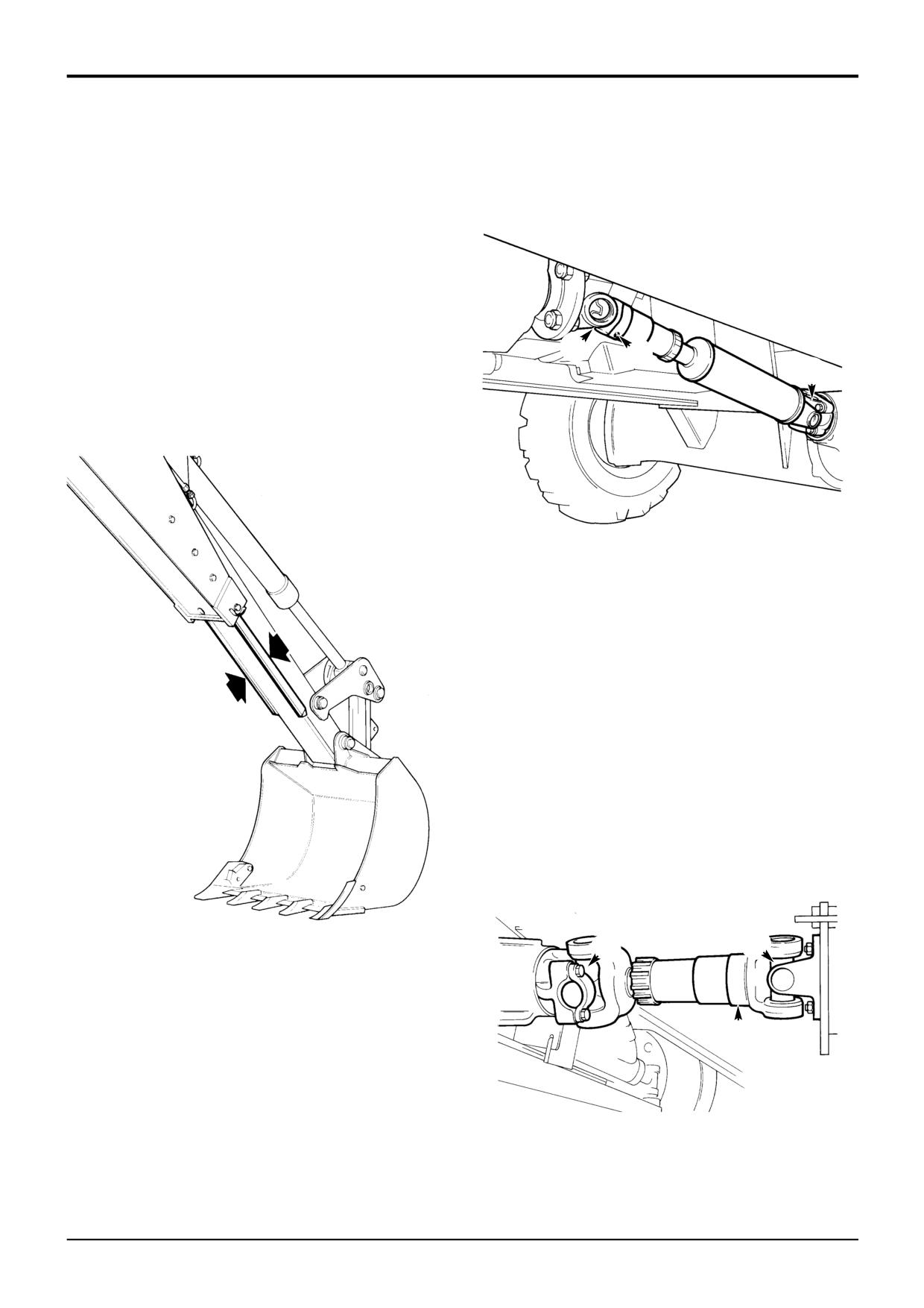
Section 3
Routine Maintenance
Section 3
9 - 5
Greasing
9 - 5
Extending Dipper
Driveshafts
Front Driveshaft
! CAUTION
3 Grease Points
Waxoyl contains turpentine substitute, which is
inflammable. Keep flames away when applying Waxoyl.
Waxoyl can take a few weeks to dry completely. Keep
flames away during the drying period.
Do not weld near the affected area during the drying
period. Take the same precautions as for oil to keep
Waxoyl off your skin. Do not breathe the fumes. Apply in
a well-ventilated area.
3
2
5-3-1-9
1
Extend the dipper. Coat the runners with Waxoyl as shown.
S157500
Rear Driveshaft
3 Grease Points
S148000
3
1
2
S157511
9803/3280
Issue 1
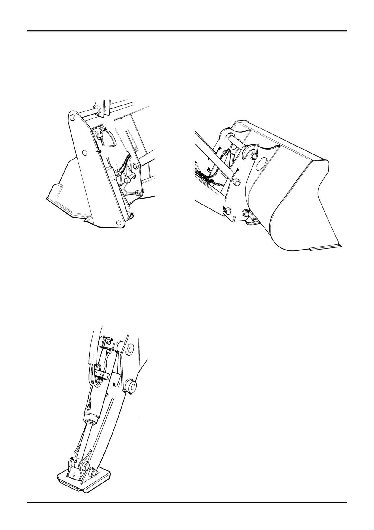
Section 3
Routine Maintenance
Section 3
9 - 6
Greasing
9 - 6
6 - In - 1 Clamshovel
Loader Quickhitch
3 grease points each end -
2 grease points each end -
Total 6 Grease Points
Total 4 Grease Points
12
3
34
1
4
2
56
S089961
S257250
Stabilisers (Centremount Machines)
3 grease points on each stabiliser -
Total 6 Grease Points
3
2
1
S259390
9803/3280
Issue 1