JCB 3CX, 4CX, 214e, 214, 215, 217 & VARIANTS Backhoe Loader. Service Manual - page 2
Section 3
Routine Maintenance
Section 3
9 - 7
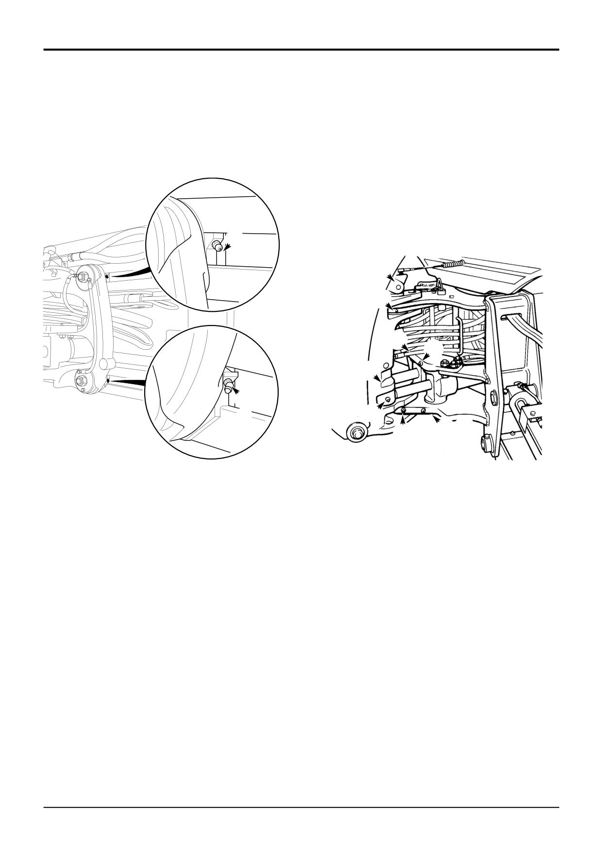
Greasing
9 - 7
Power Sideshift
Kingpost
Total 4 Grease Points
9 Grease Points
Note: Release the kingpost clamps and lower the excavator
Note: Figure shows a centremount kingpost, greasing is
to the ground before greasing.
same for sideshift kingpost.
Note: It is recommended that grease points 2 and 3 are
lubricated using a hand grease gun. The use of a power
grease gun may result in the mounting plate being distorted.
2
1
9
1
2
3
4
3
4
5
7
8
6
S254690
A326770
9803/3280
Issue 1
Section 3
Routine Maintenance
Section 3
9 - 8
Greasing
9 - 8
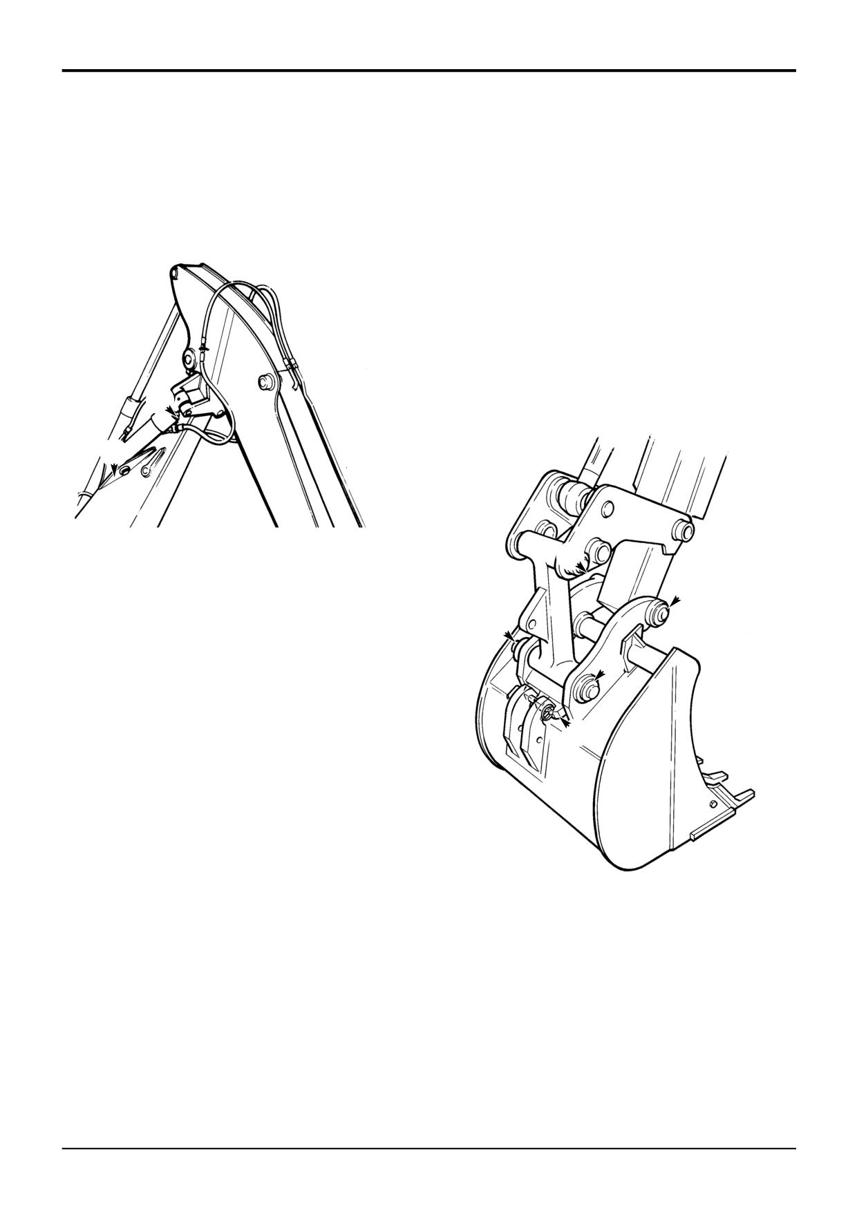
Knuckle (if fitted)
Backhoe Quickhitch (Hydraulic)
Refer to Backhoe greasing for the boom and dipper grease
! CAUTION
points.
Waxoyl contains turpentine substitute, which is
inflammable. Keep flames away when applying Waxoyl.
Total 2 Grease Points.
Waxoyl can take a few weeks to dry completely. Keep
flames away during the drying period.
Do not weld near the affected area during the drying
period. Take the same precautions as for oil to keep
Waxoyl off your skin. Do not breathe the fumes. Apply in
a well-ventilated area.
5-3-1-9
Coat the slide A with Waxoyl.
4 Grease Points
2
1
S256440
4
3
1
2
A
S211750
9803/3280
Issue 1
Section 3
Routine Maintenance
Section 3
10 - 1
Tyres and Wheels
10 - 1
Tyre Inflation
Checking the Wheel Nut Torques
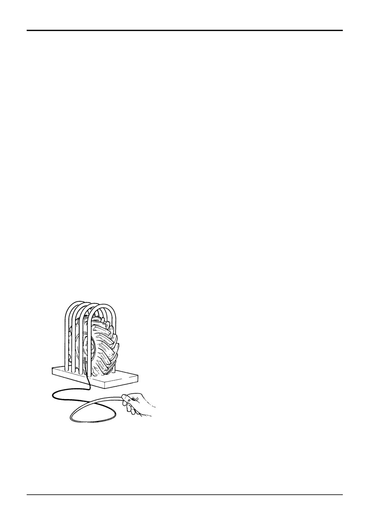
These instructions are for adding air to a tyre which is
On new machines, and whenever a wheel has been
already inflated. If the tyre has lost all its air pressure, call in
removed, check the wheel nut torques every two hours until
a qualified tyre mechanic. The tyre mechanic should use a
they stay correct.
tyre inflation cage and the correct equipment to do the job.
Every day, before starting work, check that the wheel nuts
! WARNING
are tight.
An exploding tyre can kill, inflated tyres can explode if
The correct torques are shown in the table below.
overheated. Do not cut or weld the rims. Use a
tyre/wheel specialist for all repair work.
2-3-2-7
Front - Nm
lbf ft
680
500
1
Prepare the Wheel
Before you add air to the tyre, make sure it is correctly
Rear - Nm
lbf ft
fitted on the machine or installed in a tyre inflation cage.
680
500
2
Prepare the Equipment
! WARNING
Use only an air supply system which includes a
If, for whatever reason, a wheel stud is renewed, all the
pressure regulator. Set the regulator no higher than
studs for that wheel must be changed as a set, since the
1.38 bar
(20 psi) above the recommended tyre
remaining studs may have been damaged.
pressure. See Section F, Technical Data for
2-3-2-8
recommended tyres and pressures for your machine.
Use an air hose fitted with a self-locking air chuck and
remote shut-off valve.
3
Add the Air
Make sure that the air hose is correctly connected to
the tyre valve. Clear other people from the area. Stand
behind the tread of the tyre while adding the air.
Inflate the tyre to the recommended pressure. Do not
over-inflate.
S089571
9803/3280
Issue 1
Section 3
Routine Maintenance
Section 3
11 - 1
Brakes
11 - 1
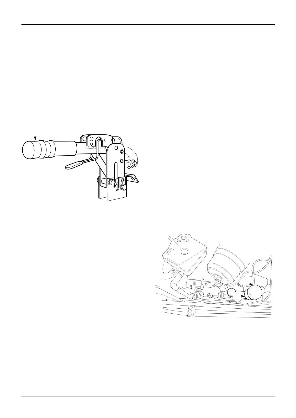
Parking Brake Adjustment
Checking the Foot Brake Fluid Level
1
Disengage the parking brake (lever horizontal).
! WARNING
Faulty brakes can kill. If you have to add oil to the brake
2
Turn handle grip E clockwise, half a turn.
reservoir regularly get the brake system checked by your
JCB Dealer. Do not use the machine until the fault has
3
Test the parking brake, see Section G, Service
been put right.
Procedures.
2-3-2-5
4
If the brake fails the test, repeat steps 1, 2 and 3. If
1
Park the machine on firm level ground, engage the
there is no more adjustment and pin F is at the end of
parking brake and set the transmission to neutral. Raise
its travel get the brake checked by your JCB Dealer.
and block the loader arms. Lower the backhoe to the
ground and stop the engine.
2
Remove the reservoir cap A and check the level. The
MAX and MIN marks are marked on the side of the
reservoir B. If necessary, add fluid as in Step 3.
E
If the level has fallen below the MIN mark, get the
system checked by your JCB Dealer.
! WARNING
Using incorrect brake fluid could damage the system.
See Service Capacities and Lubricants in
MAINTENANCE Section. The fluid can harm your skin.
Wear rubber gloves. Cover cuts and grazes.
4-3-2-3
F
3
If required, carefully pour the recommended fluid (DO
NOT USE ORDINARY BRAKE FLUID) until it reaches
347581
the correct level.
4
Refit the reservoir cap. Wipe up any spillage.
A
B
399290
9803/3280
Issue 1
Section 3
Routine Maintenance
Section 3
12 - 1
Engine Air Filter
12 - 1
Changing the Elements
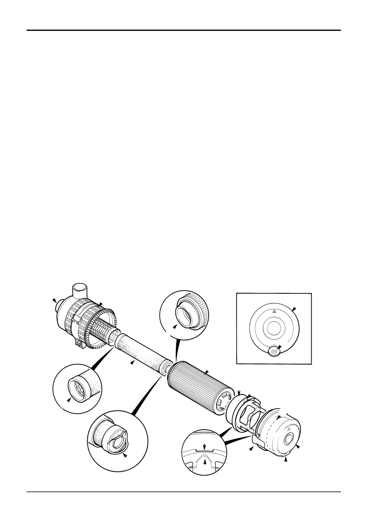
4
Depress clips B and lift off cover C. Remove outer
! CAUTION
element D. Take care not to tap or knock the element. If
The outer element must be renewed immediately if the
the inner element is to be changed, lift up pulls E and
warning light on the instrument panel illuminates.
remove inner element F. On turbocharged engines,
2-3-3-1
remove pulsation ring L.
Note: Do not attempt to wash or clean the elements - they
5
Clean inside the canister H, pulsation ring L, cover C
must only be renewed.
and dust valve J.
Note: Do not run the engine with the dust valve J removed.
6
Insert the new elements into the canister, pushing them
firmly in so that seals G and K are fully seated. On
Note: A new inner element must be fitted at least every third
turbocharged engines, assemble the pulsation ring L
time the outer element is changed. As a reminder, mark the
into the cover, making sure that tongue M fits into slot
inner element with a felt tipped pen each time the outer
N. Fit cover C with dust valve J at the bottom. Push the
element is changed.
cover firmly into position and make sure it is secured by
clips B.
1
Stop the engine.
Note: Pulsation ring L is not fitted in this application.
2
Remove the engine side panel (left hand side).
7
Refit the induction hose to stub pipe A. Make sure that
3
If changing the inner element, cover the end of the hose
the wire is connected to the Air Filter Blocked switch.
to prevent rain and dirt from getting into the engine.
A
H
C
K
J
F
D
LN
G
M
N
C
B
E
J
M
S257910
9803/3280
Issue 1
Section 3
Routine Maintenance
Section 3
13 - 1
Engine Oil and Filter
13 - 1
Checking the Oil Level
1
Make sure the park brake is engaged and the
2
Make sure the park brake is engaged and the
transmission set to neutral. Lower the loader arms and
transmission set to neutral. Lower the loader arms and
backhoe to the ground, switch OFF the engine and
backhoe to the ground, switch OFF the engine and
remove the starter key.
remove the starter key.
2
Open the bonnet, see Engine Panels, Opening and
3
Open the bonnet, see Engine Panels, Opening and
Closing the Bonnet.
Closing the Bonnet.
3
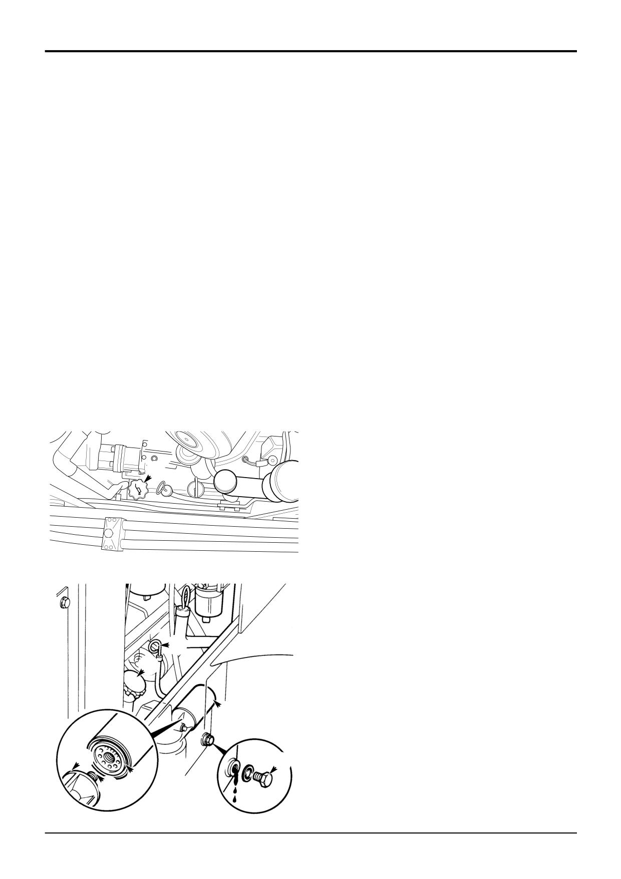
Check that the oil level is between the two marks on
4
Drain the oil:
the dipstick A.
! CAUTION
4
If necessary, remove the side panel and add oil through
Oil will gush from the hole when the drain plug is
filler B. Make sure that the dipstick and filler cap are
removed. Hot oil and engine components can burn you.
fully inserted and tightened.
Keep to one side when you remove the plug.
13-3-1-15
Changing the Oil and Filter
a Place a container of suitable size beneath the drain
plug.
1
Drain the oil when the engine is warm as contaminants
b Remove drain plug C and its 'O' ring. Let the oil
held in suspension will then be drained with the oil.
drain out, then clean and refit the drain plug with a
Park the machine on firm ground.
new 'O' ring. Tighten to 34 Nm (25 lbf ft).
! WARNING
5
Change the filter:
Make the machine safe before getting beneath it. Lower
a Unscrew the filter canister D. Remember that it will
the attachments to the ground; engage the parking
be full of oil.
brake; remove the starter key, disconnect the battery.
b Check that adapter G is secure.
2-3-2-2
c Clean the filter head F.
d Add clean engine lubricating oil to the new filter
canister. Allow enough time for the oil to pass
through the filter element.
e Smear the seal E on the new filter with oil. Screw in
the new filter canister - hand tight only.
B
6
Fill the engine to the max mark on the dipstick with new
oil through the filler. See Service Capacities and
Lubricants for recommended oil grades. Wipe off any
spilt oil. Check for leaks. Make sure the filler cap is
correctly refitted.
7
Make sure the engine will not start and turn the starter
399290
switch to operate the starter motor until the oil pressure
light is extinguished. (To make sure the engine will not
start, remove the engine shut-off solenoid fuse, housed
in the fuse box).
8
Insert the engine shut-off solenoid fuse and operate the
engine. Check for leaks. When the engine has cooled,
check the oil level.
A
B
D
F
C
E
G
S260260
9803/3280
Issue 1
Section 3
Routine Maintenance
Section 3
14 - 1
Engine Cooling System
14 - 1
Checking the Coolant
1
Make sure the park brake is engaged and the
transmission set to neutral. Lower the loader arms and
backhoe to the ground, switch OFF the engine and
! WARNING
remove the starter key.
The cooling system is pressurised when the coolant is
hot. Hot coolant will burn you. Make sure the engine is
2
Open the bonnet, see Engine Panels, Opening and
cool before checking the coolant level or draining the
Closing the Bonnet.
system.
2-3-3-3
3
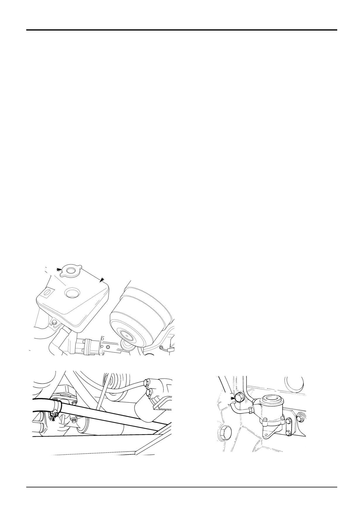
Carefully loosen cap A. Let any pressure escape.
Remove the cap.
1
Make sure the park brake is engaged and the
transmission set to neutral. Lower the loader arms and
! CAUTION
backhoe to the ground, switch OFF the engine and
remove the starter key.
Keep your face away from the drain hole when removing
the drain plug.
2
Open the bonnet, see Engine Panels, Opening and
2-3-3-4
Closing the Bonnet.
4
Remove drain plug C and let the coolant drain out.
Make sure the drain hole is not blocked.
3
The coolant level should be between the COLD/MIN
and the HOT/MAX marks on coolant reservoir B. Fill
5
Disconnect the radiator hose at D and allow the coolant
with pre-mixed water/antifreeze if necessary.
to drain. Flush the system using clean water.
Changing the Coolant
6
Clean and refit plug C. Make sure it is secure.
Reconnect the radiator hose
! WARNING
The cooling system is pressurised when the coolant is
7
Use the necessary mix of clean, soft water and
hot. Hot coolant will burn you. Make sure the engine is
antifreeze, see Coolant Mixtures. Fill to the COLD/MIN
cool before checking the coolant level or draining the
level on coolant reservoir B.
system.
2-3-3-3
8
Start the engine and run at idle to circulate the coolant,
top up with coolant as necessary.
9
Refit the filler cap. Make sure it is tight.
A
B
10
Run the engine for a while, to raise the coolant to
working temperature and pressure. Stop the engine.
Check for leaks.
Note: Make sure the cab heater control is in the hot
position. This will ensure the coolant mixture circulates
through the entire cooling system.
399290
C
D
S148060
S260270
9803/3280
Issue 1
Section 3
Routine Maintenance
Section 3
14 - 2
Engine Cooling System
14 - 2
Adjusting the Fan Belt
Cleaning the Cab Heater Filter
1
Park the machine on firm level ground, engage the
! WARNING
parking brake and set the transmission to neutral.
Make sure the engine cannot be started. Disconnect the
Lower the attachments to the ground and stop the
battery before doing this job.
engine.
2-3-3-5
2
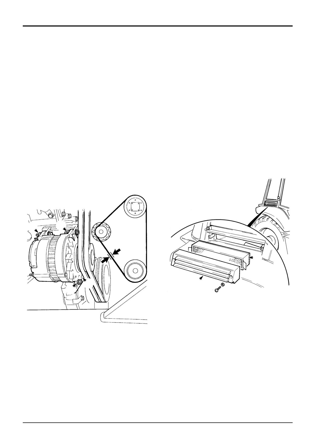
Remove the cover retaining screws (2 off) and then
1
Park the machine on firm level ground, engage the
remove the cover, item E.
parking brake and set the transmission to neutral. Raise
and block the loader arms. Lower the backhoe to the
3
Knock loose dust off the filter F. Carefully blow
ground and stop the engine.
compressed air through all the folds of the filter, blow in
the opposite direction to the arrows marked on the
2
Loosen pivot fastening bolts A and B. Loosen
filter.
adjustment link fastening bolts C and D.
Note: The compressed air must be set at a pressure no
3
Position the alternator so that there is 10 mm (3/8 in)
greater than 7 bar (100 lb/in2).
slack at point X.
4
Refit the cover E and secure with the retaining screws
4
Tighten bolts C and D, then bolts A and B.
(2 off).
Note: If a new belt is fitted, the belt tension must be
checked again after the first 20 hours of operation.
A
B
X
F
E
D
C
S254720
S209411
9803/3280
Issue 1
Section 3
Routine Maintenance
Section 3
15 - 1
Fuel System
15 - 1
Types of Fuel
Low Temperature Fuels
Use good quality diesel fuel to get the correct power and
Special winter fuels may be available for engine operation at
performance from your engine. The recommended fuel
temperatures below 0°C (32°F). These fuels have a lower
specification for engines is given below.
viscosity. They also limit wax formation in the fuel at low
temperatures. (Wax forming in the fuel can stop the fuel
Cetane Number: 45(minimum)
flowing through the filter.)
Viscosity:
2.5/4.5 centistokes at 40 °C (104 °F)
Density:
0.835/0.855 kg/litre
Flow improvers may also be available. These can be added
(0.872/0.904 lb/pint)
to the fuel to reduce wax formation.
Sulphur:
0.5% of mass (maximum)
Distillation:
85% at 350 °C (662 °F)
Fatty Acid Methyl Ester Fuels as a replacement for
Diesel Fuels
Cetane Number
Fuel resources such as Rape Methyl Ester and Soybean
Indicates ignition performance. Fuel with a low cetane
Methyl Ester, collectively known as Fatty Acid Methyl Esters
number can cause cold start problems and affect
are being used as alternatives and extenders for mineral oil.
combustion.
Fatty Acid Methyl Esters must conform to certain standards
Viscosity
to be of acceptable quality, just as mineral oils do at
Is the resistance to flow. If this is outside limits, the engine
present.
performance can be affected.
Consult your JCB distributor for advice about the use of
Fatty Acid Methyl Ester fuels, as improper application may
Density
impair engine performance.
Lower density will reduce engine power. Higher density will
increase both engine power and exhaust smoke.
Petrol
Sulphur
! WARNING
High sulphur content can cause engine wear. (High sulphur
Do not use petrol in this machine. Do not mix petrol with
fuel is not normally found in North America, Europe or
the diesel fuel; in storage tanks the petrol will rise to the
Australia.) If you have to use high sulphur fuel you must also
top and form flammable vapours.
use a highly alkaline engine lubricating oil; or change the
INT-3-1-6
normal oil more frequently.
Advice
Low sulphur fuels are commonly used throughout the world.
If you have to use non-standard fuels, contact your JCB
These fuels contain fewer lubrication additives. The fuel
distributor for advice on engine adjustments and oil change
injection pumps fitted to the engine (with exception of
periods.
160TW, Euro 1 engine) are lubricated by the fuel; therefore
using low sulphur fuel may, in the long term, affect the
! WARNING
pump.
Diesel fuel is flammable; keep naked flames away from
If you have to use low sulphur fuel you are advised to use a
the machine. Do not smoke while refuelling the machine
lubrication additive as recommended by your fuel supplier.
or working on the engine. Do not refuel with the engine
running. There could be a fire and injury if you do not
Distillation
follow these precautions.
INT-3-2-2
This indicates the mixture of different hydrocarbons in the
fuel. A high ratio of lightweight hydrocarbons can affect the
combustion characteristics.
Fuel Standards
Consult your fuel supplier, JCB distributor about the
suitability of any fuel you are unsure of.
9803/3280
Issue 1
Section 3
Routine Maintenance
Section 3
15 - 2
Fuel System
15 - 2
Filling the Tank
! WARNING
Lower the loader arms and switch off the engine before
refuelling. Do not permit operation of the machine
controls while refuelling.
2-3-3-9
At the end of every working day, fill the tank with the correct
type of fuel. This will prevent overnight condensation from
developing in the fuel.
The cap incorporates a side mounted barrel lock that is
operated by the ignition/door key.
A
Fit the Cap
B
Once the key has been removed, the cap will simply rotate
on the filler neck. To remove the cap from the filler neck, the
key must be reinserted and the cap unlocked.
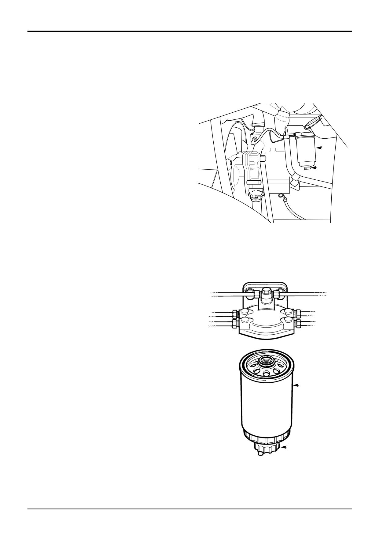
Draining the Filter
1
Park the machine on firm level ground, engage the
399470
parking brake and set the transmission to neutral. Raise
and block the loader arms. Lower the backhoe to the
ground and stop the engine.
2
Drain off any water in the element A by turning tap B
Changing the Filter Element
1
Park the machine on firm level ground, engage the
parking brake and set the transmission to neutral.
Lower the loader arms and backhoe to the ground, stop
the engine.
2
Unscrew the filter element A. The element is hand tight
but may require a strap wrench to remove. The filter will
be full of fuel.
3
To assist with bleeding, fill the new filter element with
fuel before fitting. Install new element A hand tight only.
Check for leaks.
4
Bleed the System.
A
S233870
B
9803/3280
Issue 1
Section 3
Routine Maintenance
Section 3
15 - 3
Fuel System
15 - 3
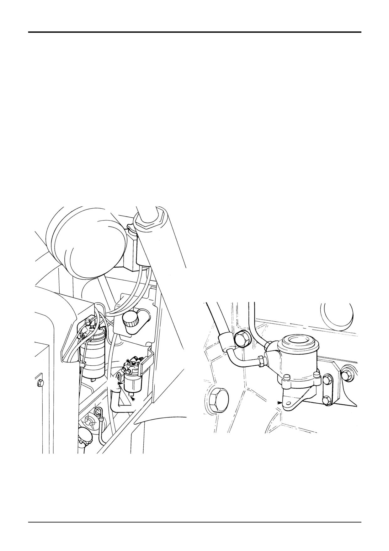
Draining the Sediment Bowl
Bleed the System
1
Park the machine on firm level ground, engage the
! CAUTION
parking brake and set the transmission to neutral.
Running the engine with air in the system could damage
Lower the loader arms and backhoe to the ground, stop
the fuel injection pump. After maintenance, remove air
the engine.
from the system as detailed below.
2-3-3-7
2
Look in bowl A. If it contains sediment, do Steps 3 to 6.
If there is water but no sediment, drain off the water by
1
Park the machine on firm level ground, engage the
parking brake and set the transmission to neutral.
opening tap B. Make sure tap B is turned off and
Lower the loader arms and backhoe to the ground and
secure.
stop the engine.
3
Support bowl A; unscrew nut C. Remove the bowl.
2
Set the starter key to the IGN position.
4
Wash the bowl. Use clean fuel.
! WARNING
5
Refit the bowl, make sure gasket is seated correctly.
Hot oil and engine components can burn you. Make sure
the engine is cool before doing this job.
6
Bleed the System.
2-3-3-2
3
Operate the fuel lift pump priming lever X slowly, for
approximately two minutes. The engine is now ready to
start. If the engine runs smoothly for a short time, and
then begins to run roughly or stops, check again for air
in the fuel system. Check all seals and connections,
especially in the low pressure side of the system.
Note: If no fuel is moved when the fuel lift pump priming
lever X is operated, then the pump diaphragm may have
rested in a 'maximum lift' position. To move the diaphragm,
use the starter key to turn the engine, then try the priming
lever again.
C
A
B
X
S148060
S260120
9803/3280
Issue 1
Section 3
Routine Maintenance
Section 3
16 - 1
Synchro Shuttle Gearbox
16 - 1
Checking the Oil Level
Changing the Oil and Filter
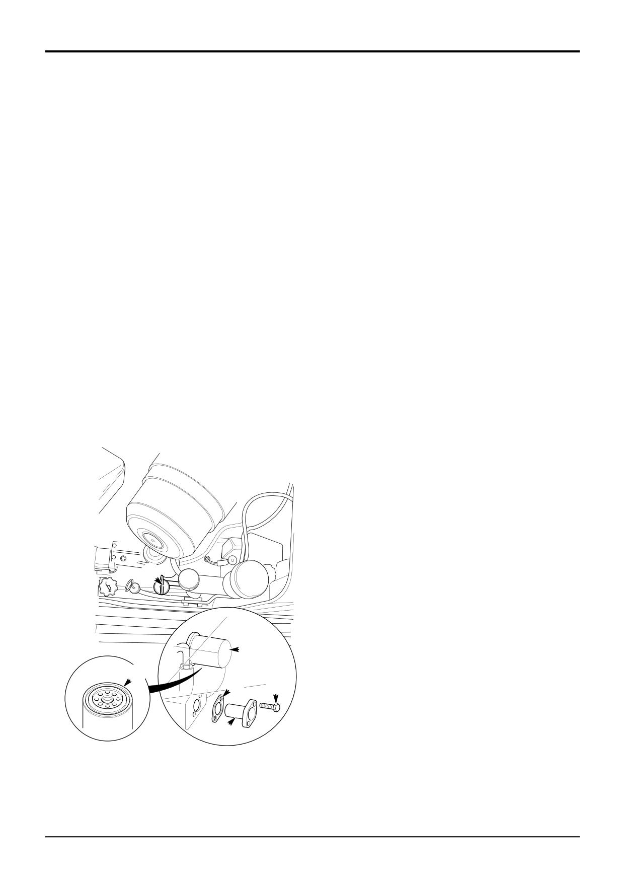
1
Make sure the park brake is engaged and the
The transmission oil should be drained through the suction
transmission set to neutral. Lower the loader arms and
strainer aperture to flush out any particles which fall off the
backhoe to the ground, switch OFF the engine and
strainer during its removal.
remove the starter key.
! WARNING
2
Open the bonnet, see Engine Panels, Opening and
Make the machine safe before getting beneath it. Lower
Closing the Bonnet.
the attachments to the ground; engage the parking
brake; remove the starter key, disconnect the battery.
3
Switch OFF the engine and remove the starter key, fill
2-3-2-2
the transmission to maximum mark on dipstick/filler A.
Use only the recommended oil.
1
Park the machine on level ground. Engage the parking
brake. Lower the attachments to the ground. Stop the
4
Start and run the engine slowly for a period not
engine. Remove the starter key. Disconnect the battery.
exceeding five minutes. This allows the oil to fill filter,
pump, torque converter, oil cooler and hoses.
! CAUTION
When the strainer is removed, oil will gush out. Keep to
5
Switch OFF the engine and remove the starter key, wait
one side when you remove the strainer.
approximately 20 seconds. Check the oil level and if
2-3-4-1
required, fill to dipstick level.
2
Place a container, of suitable size beneath the drain
plug. Remove bolts D. Pull out the strainer E and its
gasket F. Allow the oil to drain into the container.
3
Clean the strainer with a suitable solvent. Follow the
solvent manufacturer's instructions on safety.
4
Fit the strainer E and a new gasket F. Apply JCB
Threadlocker and Sealer to bolts D before fitting and
tightening them. Torque tighten the bolts to 10 Nm (7
lbf ft).
5
Unscrew and remove the filter B. Fit the new filter:
5.1 Smear seal C with transmission oil.
5.2 Screw the filter on until it just contacts the filter
head.
5.3
Turn the filter at least another 3/4 of a turn.
6
Fill the system with new oil through the dipstick/filler A.
A
Do not fill past the top mark on the dipstick.
Note: Fit only a genuine supplied JCB filter, otherwise
damage to the system may be incurred through
contamination.
B
C
F D
E
399310
9803/3280
Issue 1
Section 3
Routine Maintenance
Section 3
17 - 1
Powershift Gearbox
17 - 1
Checking the Oil Level
1
Make sure the park brake is engaged and the
transmission set to neutral. Lower the loader arms and
backhoe to the ground, switch OFF the engine and
remove the starter key.
2
Open the bonnet, see Engine Panels, Opening and
Closing the Bonnet.
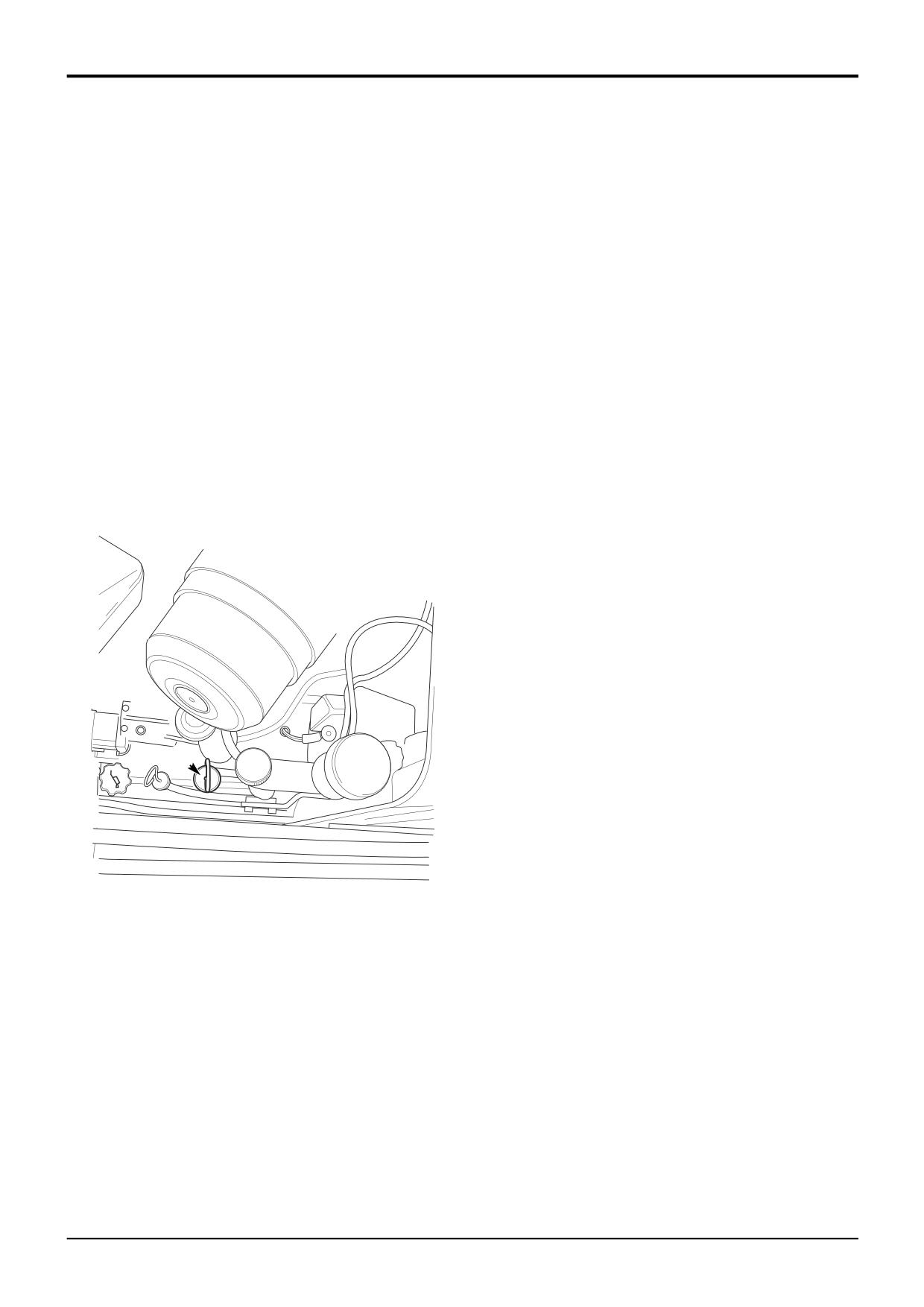
3
Switch OFF the engine and remove the starter key, fill
the gearbox to maximum mark on dipstick/filler A. Use
only the recommended oil.
4
Start and run the engine slowly for a period not
exceeding five minutes. This allows the oil to fill filter,
pump, torque converter, oil cooler and hoses.
5
Switch OFF the engine and remove the starter key, wait
approximately 20 seconds. Check the oil level and if
required, fill to dipstick level.
A
A405230
9803/3280
Issue 2*
Section 3
Routine Maintenance
Section 3
17 - 2
Powershift Gearbox
17 - 2
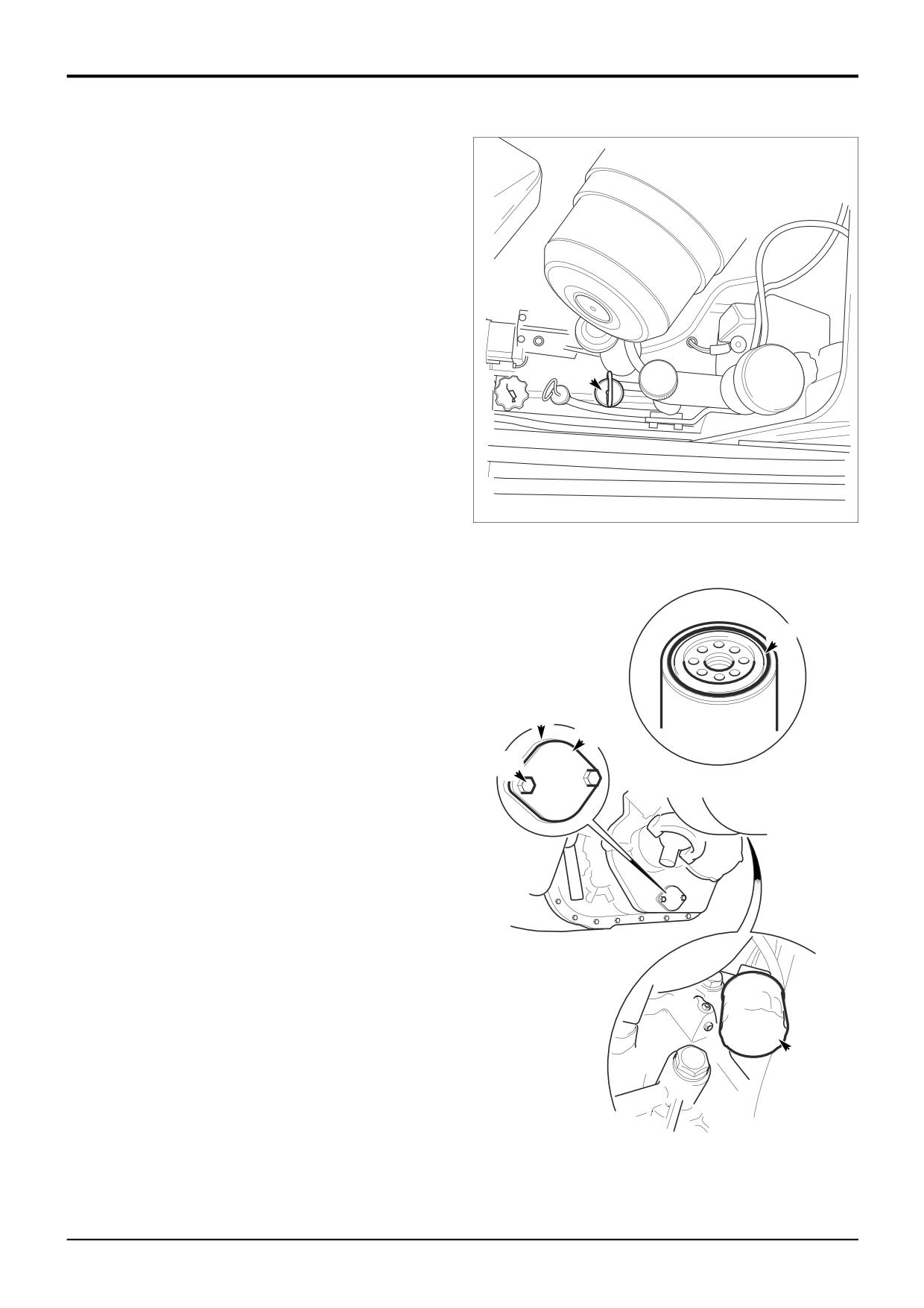
Changing the Oil and Filter
When draining JCB 760 Series Powershift gearboxes it is
recommended that the oil is drained through the cover plate
A to make sure that the debris collected in the transmission
sump is flushed out. Draining oil through the sump plug will
filter oil through the strainer and not flush out the debris.
! WARNING
Make the machine safe before getting beneath it. Lower
the attachments to the ground; engage the parking
brake; remove the starter key, disconnect the battery.
2-3-2-2
F
1
Park the machine on firm level ground, apply the park
brake. Lower the loader arms, open the engine bonnet,
raise the loader arms and fit the safety strut. Lower the
excavator to the ground, switch OFF the engine and
remove the starter key.
2
Apply the parking brake and disconnect the battery,
A405230
remove the engine side panels.
3
Place a container of suitable size beneath the
transmission to catch the oil.
4
Remove bolts B. Pull off cover plate A and gasket C,
allow the oil to drain into the container. Be aware that
the oil may be hot.
E
Note: When the cover is removed oil will gush out. Keep to
one side when you remove the cover plate.
5
Fit cover plate A and a new gasket C. Apply JCB
C
Threadlocker and Sealer to bolts B before fitting them.
A
Torque tighten the bolts to 28 Nm (20.5 lbf ft.).
B
6
Unscrew and remove the filter D. Fit the new filter:
6.1 Smear seal E with transmission oil.
6.2 Screw the filter on until it just contacts the filter
head.
6.3 Turn the filter at least another 3/4 of a turn.
7
Fill the system with new oil through the dipstick/filler F.
Do not fill past the top mark on the dipstick.
8
On completion check for oil leaks.
Note: Fit only a genuine supplied JCB filter, otherwise
damage to the system may be incurred through
contamination.
D
A405170
9803/3280
Issue 1
Section 3
Routine Maintenance
Section 3
18 - 1
Hydraulic System
18 - 1
Checking the Fluid Level
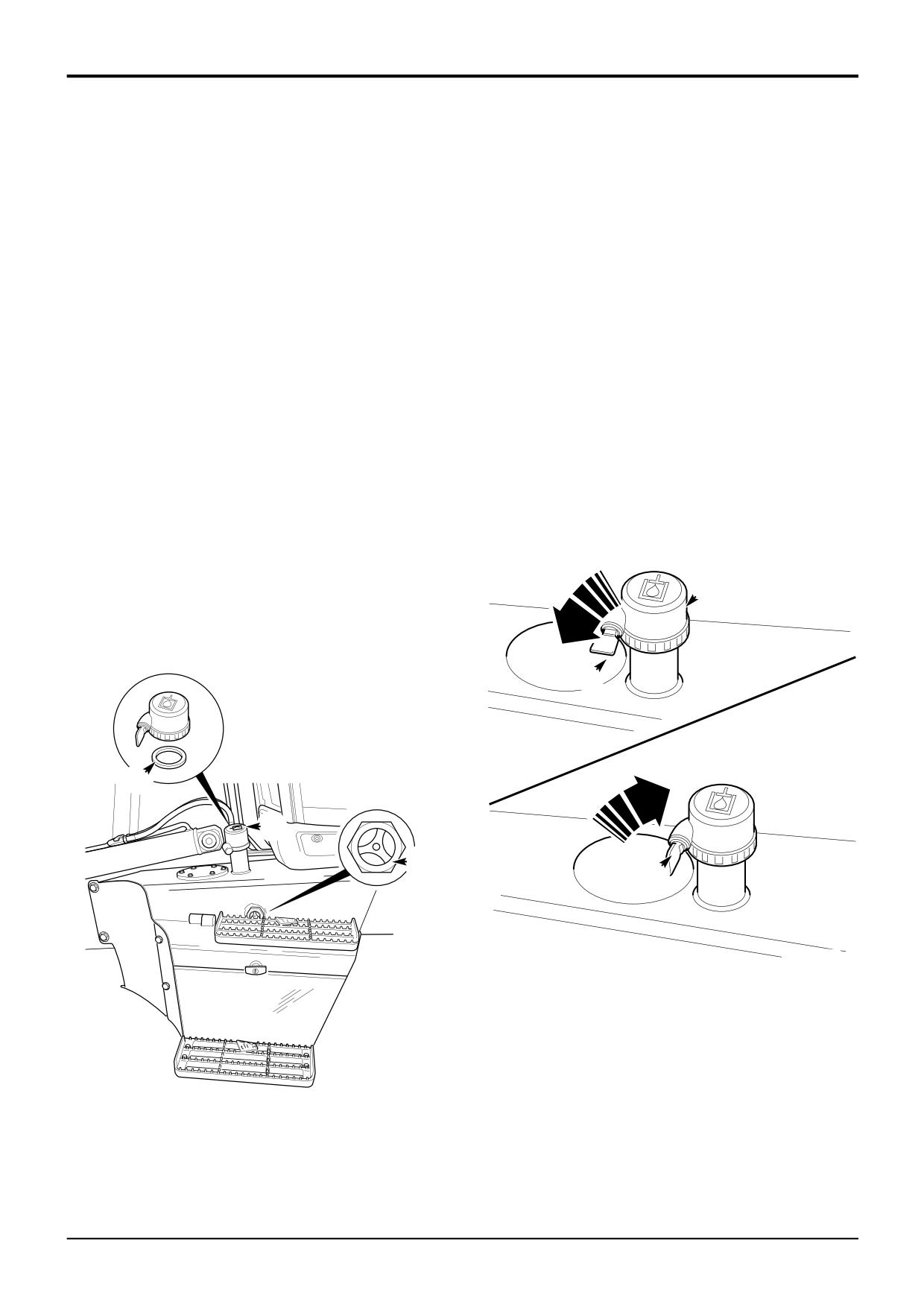
Hydraulic Tank Cap
! WARNING
The hydraulic tank breather (and filter) forms an integral part
of the hydraulic tank cap B. Replace the cap (and breather
Fine jets of hydraulic fluid at high pressure can penetrate
filter) with a new one at the recommended interval, see
the skin. Do not use your fingers to check for hydraulic
Service Schedules.
fluid leaks. Do not put your face close to suspected
leaks. Hold a piece of cardboard close to suspected
The cap incorporates a side mounted barrel lock that is
leaks and then inspect the cardboard for signs of
operated by the ignition/door key. It is important to note that
hydraulic fluid. If hydraulic fluid penetrates your skin, get
seal C must be in good condition and correctly installed in
medical help immediately.
INT-3-1-10/1
the cap.
1
Position the machine on level ground. Set the loader
Fit the Cap
shovel on the ground. Retract the extending dipper if
fitted. Raise the boom, swing in the dipper and close
Insert the key and turn anticlockwise D, screw the cap on
the bucket. Stop the engine. Remove the starter key.
until resistance is felt then turn a further quarter of a turn,
turn the key clockwise E and remove the key. With the key
2
Look at the fluid level in the sight glass A. The level
removed the cap will rotate and can not be undone.
should be at the red mark (or above).
Remove the Cap
! CAUTION
Insert the key and turn anticlockwise D, unscrew the cap.
If the fluid in the tube appears cloudy, then water or air
has entered the system. The hydraulic pump could be
severely damaged if the machine is operated. Contact
your JCB distributor immediately.
2-3-4-3
B
3
If the oil level is low, remove filler cap B and replenish
with recommended hydraulic oil as required.
D
C
B
A
E
A329760
399330
9803/3280
Issue 1
Section 3
Routine Maintenance
Section 3
18 - 2
Hydraulic System
18 - 2
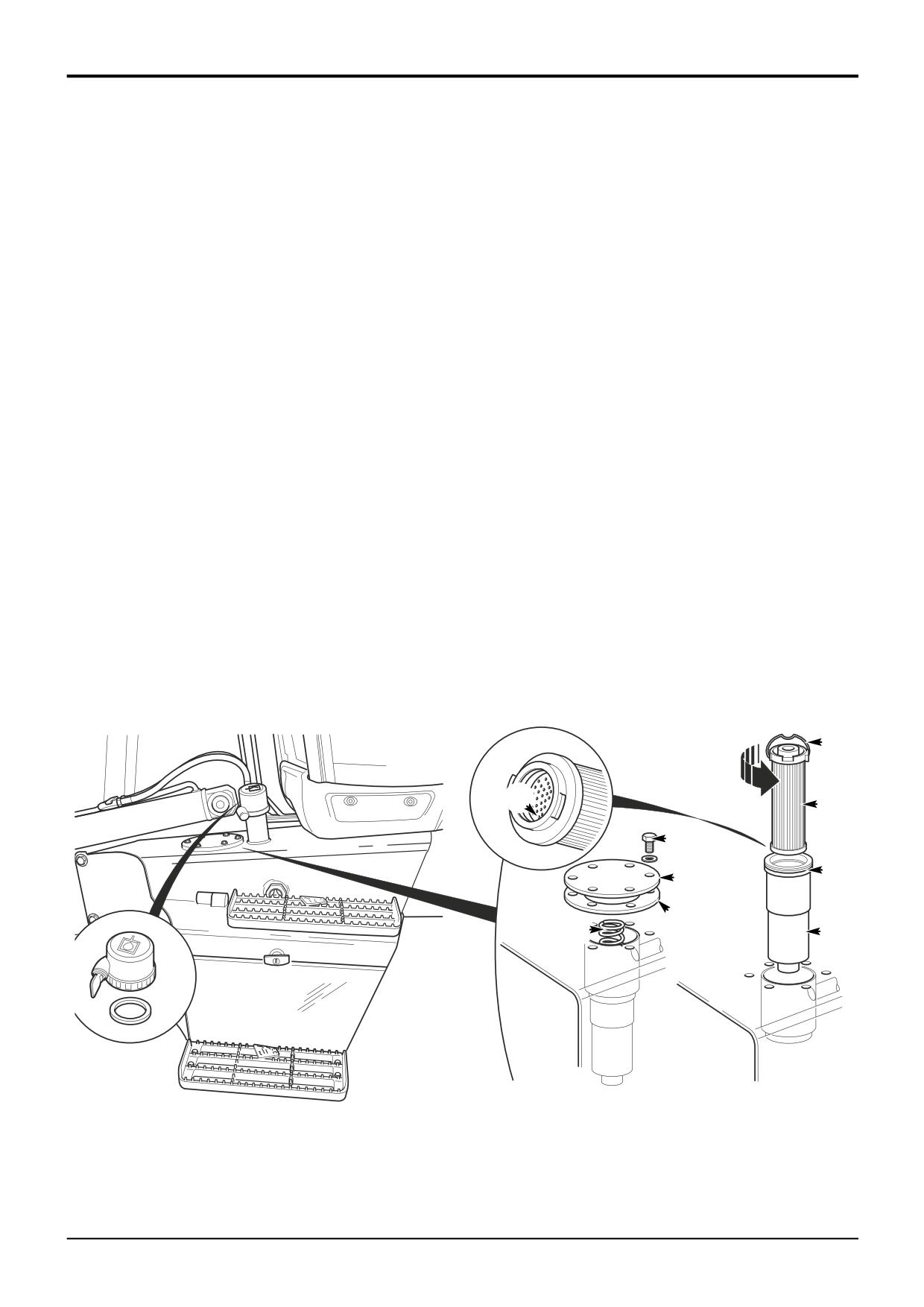
Changing the Filter Element
! WARNING
3
Remove the element from its canister.
Fine jets of hydraulic fluid at high pressure can penetrate
a Hold canister F.
the skin. Do not use your fingers to check for hydraulic
b Hold handle E and rotate the element G 90° anti-
fluid leaks. Do not put your face close to suspected
clockwise.
leaks. Hold a piece of cardboard close to suspected
c Pull on handle E, the element G should separate
leaks and then inspect the cardboard for signs of
from its canister F. Discard the old element.
hydraulic fluid. If hydraulic fluid penetrates your skin, get
medical help immediately.
d Remove and discard seal H.
INT-3-1-10/1
e Clean the inside of canister F.
1
Position the machine on level ground. Roll the loader
shovel forward and rest it on the ground. Retract the
New machines are fitted with a 5 micron filter element which
extending dipper if fitted. Close the backhoe bucket.
must be replaced at the first 100 hour service with a 10
Swing in the dipper. Lower the boom until the bucket
micron filter element.
rests on the ground. Lower the stabilisers to the
ground. Stop the engine. Remove the starter key.
4
Fit the new element.
a Fit a new seal H.
2
Remove the element assembly
b Make sure that seal J is fitted in the new element.
a Remove screws A. Remove the cover plate B and
c Push the element G into its canister F and rotate the
gasket C
element 90° to lock it into position. Check that the
* Note: If gasket C is a rubber type it can be reused provided
element has locked into position by pulling on
it is undamaged. If the gasket is a cork type it must be
handle E.
discarded and a new gasket fitted on assembly.
d Install the element assembly in the hydraulic tank.
b Remove spring D.
e Fit spring D and gasket C, (see ‘Note’ at step 2).
*
c Hold handle E and pull the element assembly from
f Fit cover plate B and tighten screws A to 21 Nm
the hydraulic tank.
(15.5 lbf ft).
g Check oil level and replenish as required through
filler. Fit and tighten the filler cap as described on
previous page.
E
J
G
A
H
B
C
D
F
399340
9803/3280
Issue 2*
Section 3
Routine Maintenance
Section 3
18 - 3
Hydraulic System
18 - 3
Changing the Suction Strainer
! WARNING
Make the machine safe before getting beneath it. Lower
the attachments to the ground; engage the parking
brake; remove the starter key, disconnect the battery.
2-3-2-2
1
Position the machine on level ground. Roll the loader
shovel forward and rest it on the ground. Retract the
extending dipper if fitted. Close the backhoe bucket.
B
Swing in the dipper. Lower the boom until the bucket
rests on the ground. Lower the stabilisers to the
ground. Stop the engine. Remove the starter key and
disconnect the battery.
2
Remove hydraulic tank filler cap.
3
Place a container beneath the hydraulic tank to catch
the oil, remove drain plug and drain the hydraulic tank.
Make sure the container is large enough to hold the
tank contents, see Service Capacities and
Lubricants.
A
A
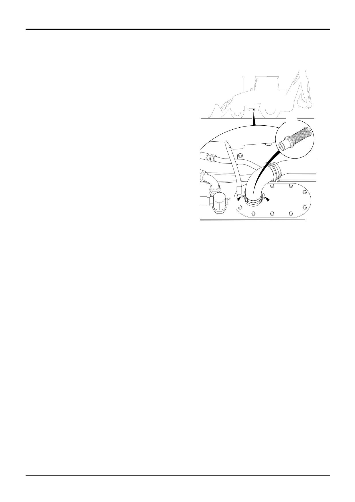
4
Undo clips A and disconnect the hydraulic return pipe.
A334050
5
Using a 65mm A/F spanner unscrew suction strainer B
and discard.
6
Fit a new filter assembly B, torque tighten to 15-20 Nm
(11-15 lbf ft).
7
Reconnect suction hose. Make sure the clips A are
positioned 180° apart.
8
Refit drain plug, torque tighten to 100 Nm (74 lbf ft).
9
Refill hydraulic tank, fit and tighten the filler cap, see
Hydraulic Tank Cap.
9803/3280
Issue 1
Section 3
Routine Maintenance
Section 3
19 - 1
Front and Rear Axle (All Wheel Steer Machines)
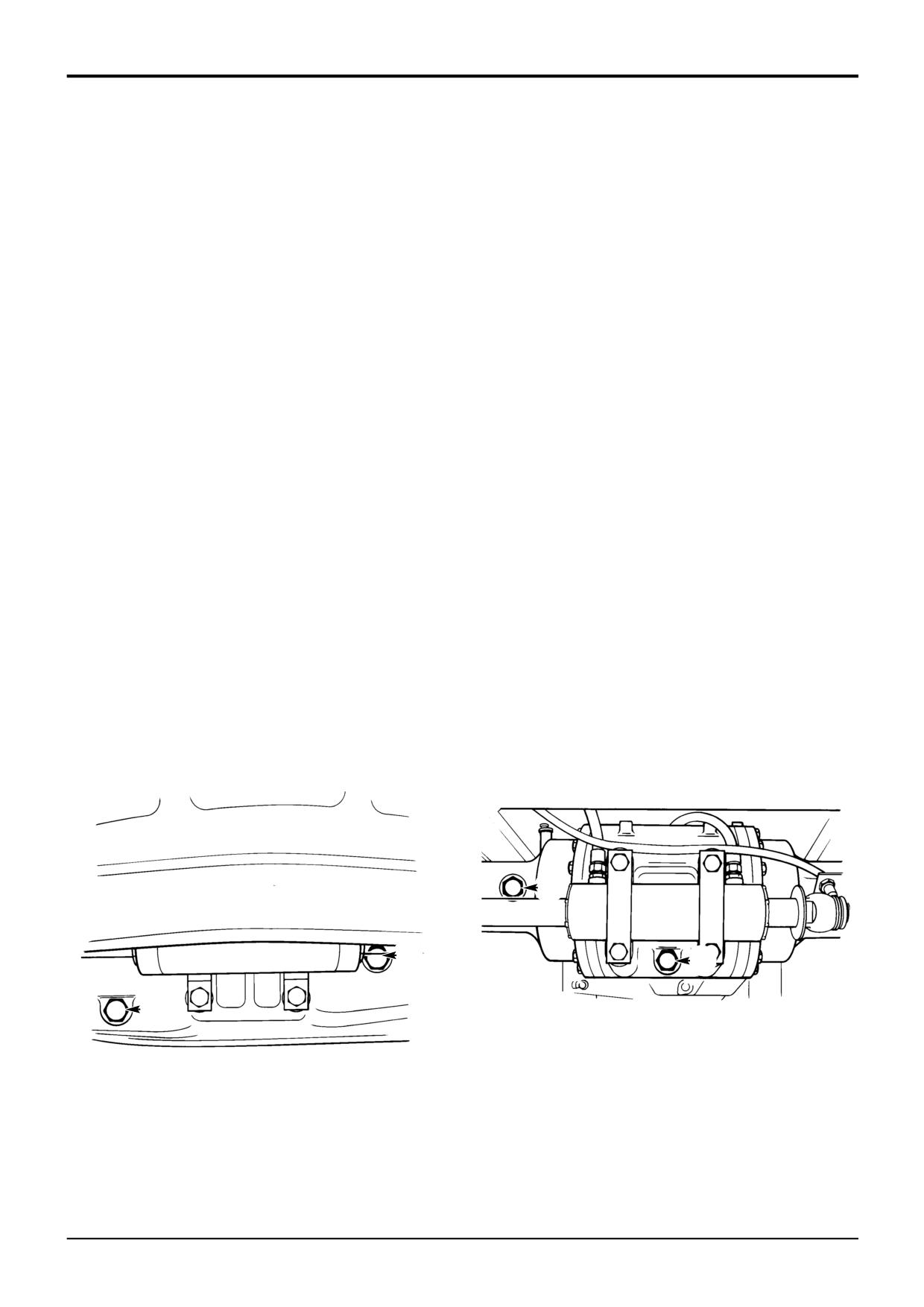
19 - 1
Checking the Differential Oil Level
Changing the Differential Oil
! WARNING
! WARNING
Make the machine safe before getting beneath it. Lower
Make the machine safe before getting beneath it. Lower
the attachments to the ground; engage the parking
the attachments to the ground; engage the parking
brake; remove the starter key, disconnect the battery.
brake; remove the starter key, disconnect the battery.
2-3-2-2
2-3-2-2
! CAUTION
1
Park the machine on level ground. Engage the parking
brake. Set the transmission to neutral. Lower the
The axle oil level must be checked with the machine
attachments to the ground. Stop the engine and
level, otherwise a false indication of the amount of oil in
remove the starter key.
the axle will be given.
16-3-5-3
2
Place a container of suitable size beneath plug B to
1
Park the machine on level ground. Engage the parking
catch the oil. Remove the drain plug B and its seal.
brake. Set the transmission to neutral. Lower the
Allow oil to drain out. The drain plug is magnetic. Wipe
attachments to the ground. Stop the engine and
it clean. (Metallic particles should be carefully
remove the starter key.
removed). Fit drain plug B and its washer. Tighten to
79 Nm (60 lbf ft).
2
Clean the area around fill/level plug A, then remove the
plug and its sealing washer. Oil should be level with the
3
Fill with recommended oil through fill/level hole A.
bottom of the hole. Add recommended oil if necessary.
Clean and refit plug A and its seal. Tighten to 79 Nm
(60 lbf ft).
3
Clean and refit the plug and its washer.
FRONT
REAR
S260420
A
A
B
B
S260430
9803/3280
Issue 1
Section 3
Routine Maintenance
Section 3
19 - 2
Front and Rear Axle (All Wheel Steer Machines)
19 - 2
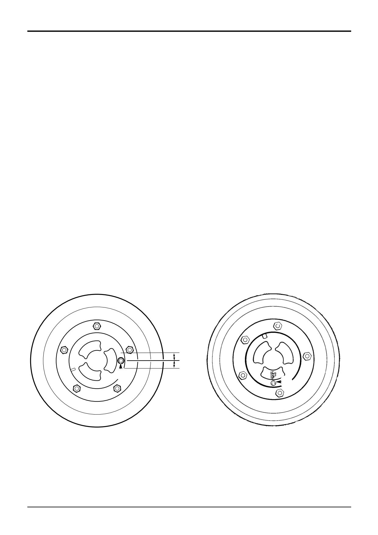
Checking the Hub Oil Levels
Changing the Hub Oil
Check each hub separately.
The axle oil is used to lubricate the brake components and
cool the brake plates.
1
Park the machine on level ground with the OIL LEVEL
mark horizontal. There is a tolerance of 5 mm (0.2 in)
It is important that the oil is changed regularly as specified in
above or below the horizontal.
the service schedule - the lubricating properties of the oil will
reduce as a result of brake wear.
2
Engage the parking brake. Set the transmission to
neutral. Lower the attachments to the ground. Stop the
Consult your JCB distributor for advice if necessary.
engine and remove the starter key.
Change the oil in each hub separately
3
Clean the area around the fill/level plug C. Remove the
plug. Oil should be level with the bottom of the hole. If
1
Set the machine level, with the tyres just clear of the
necessary, add the recommended oil. Clean the plug
ground. Manually rotate the wheels to bring the OIL
before refitting it.
LEVEL mark on the hubs to the vertical position, with
the fill/level plugs C at the bottom.
2
a Place a container of suitable size beneath plug C to
catch the oil.
b Remove fill/level plugs C. Allow time for the oil to
drain out.
3
a Set OIL LEVEL marks to the horizontal.
b Fill the hubs with recommended axle oil, through the
fill/level holes C. Oil should be level with the bottom
of the fill/level hole.
c Clean and refit fill/level plugs C.
OIL
LEVEL
C
C
356040
S209320
9803/3280
Issue 1
Section 3
Routine Maintenance
Section 3
19 - 3
Front and Rear Axle (Two Wheel Steer Machines)
19 - 3
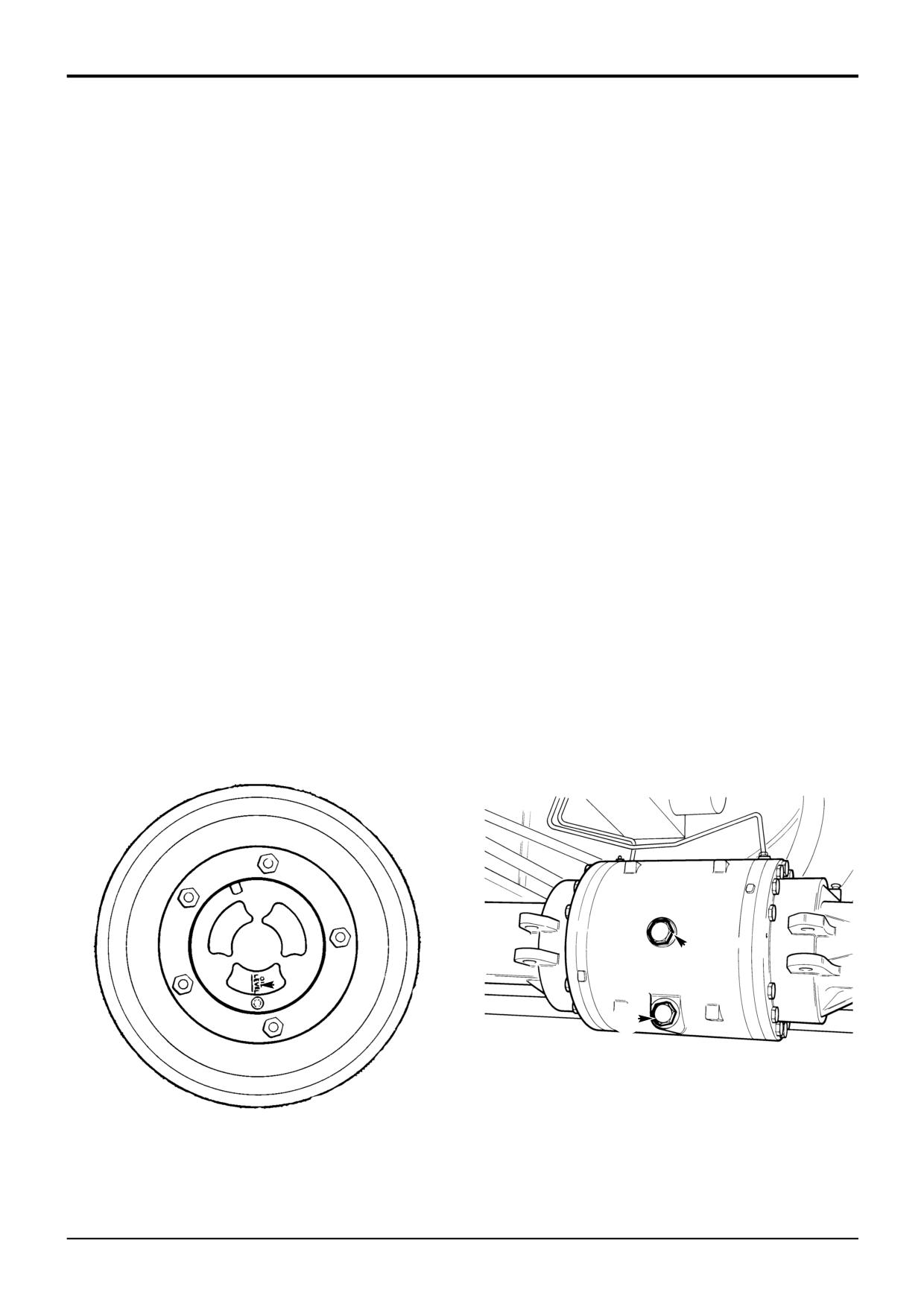
The front axle procedures are the same as described on the
1
Park the machine on level ground so that the 'OIL
previous pages (all wheel steer machines). Refer to the
LEVEL' mark on one hub is at the bottom, as shown in
following procedures for checking and changing the oil on
fig. 1. Engage the parking brake. Set the transmission
the rear axle.
to neutral. Lower the attachments to the ground. Stop
the engine and remove the starter key.
Checking the Oil Level
2
Place a container of suitable size beneath fill/level plug
C to catch the oil. Remove the fill/level plug C from the
! CAUTION
hub. Allow the oil to drain out. The drain plug is
The axle oil level must be checked with the machine
magnetic. Wipe it clean. (Metallic particles should be
level, otherwise a false indication of the amount of oil in
carefully removed). Clean and refit the hub fill/level plug
the axle will be given.
C.
16-3-5-3
3
Position the other wheel of the rear axle so that the
1
Park the machine on level ground. Engage the parking
'OIL LEVEL' mark on its hub is at the bottom. Repeat
brake. Set the transmission to neutral. Lower the
step 2.
attachments to the ground. Stop the engine and
remove the starter key.
4
Place a container of suitable size beneath the drain
plug B to catch the oil.
2
Clean the area around fill/level plug A, then remove the
plug and its sealing washer. Oil should be level with the
! CAUTION
bottom of the hole. Add recommended oil if necessary.
Oil will gush from the hole when the drain plug is
removed. Keep to one side when you remove the plug.
3
Clean and refit the plug and its washer.
2-3-4-2
Changing the Oil
Remove the drain plug B. Allow the oil to drain out. The
drain plug is magnetic. Wipe it clean. (Metallic particles
The axle oil is used to lubricate the brake components and
should be carefully removed). Clean and refit the drain
cool the brake plates.
plug B.
It is important that the oil is changed regularly as specified in
5
Remove fill/level plug A. Fill the axle with the specified
the service schedule - the lubricating properties of the oil will
quantity and recommended type of oil. Clean and refit
reduce as a result of brake wear.
fill/level plug A.
Consult your JCB distributor for advice if necessary.
1
A
C
B
S145210
S209320
9803/3280
Issue 1
Section 3
Routine Maintenance
Section 3
21 - 1
Battery
21 - 1
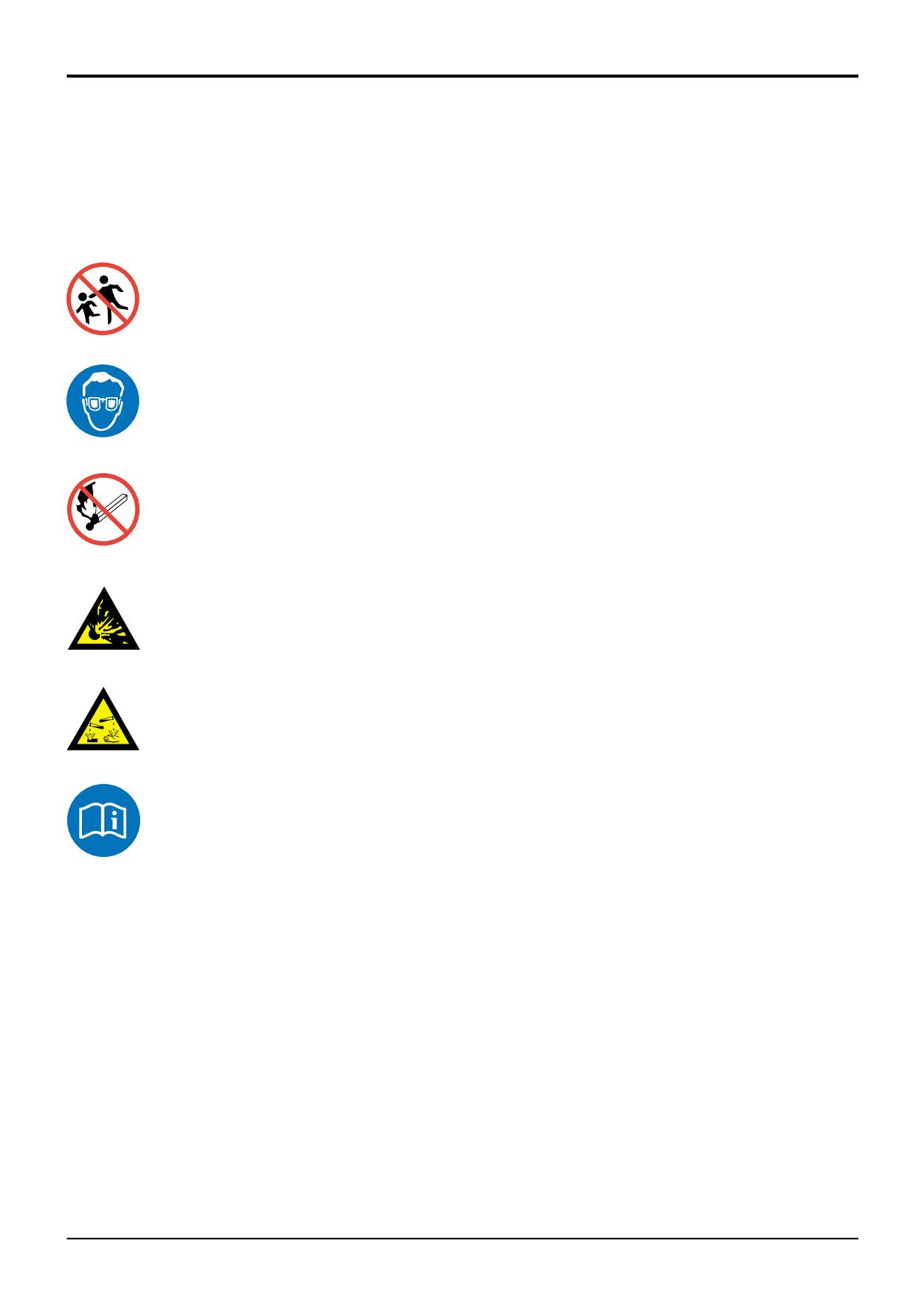
Warning Symbols
! CAUTION
The following warning symbols may be found on the battery.
Do not disconnect the battery while the engine is
running, otherwise the electrical circuits may be
damaged.
Symbol
Meaning
INT- 3- 1-14
! WARNING
Understand the electrical circuit before connecting or
Keep away from children.
disconnecting an electrical component. A wrong
connection can cause injury and/or damage.
INT-3-1-4
A289230
! DANGER
Battery electrolyte is toxic and corrosive. Do not
Shield eyes.
breathe the gases given off by the battery. Keep the
electrolyte away from your clothes, skin, mouth and
eyes. Wear safety glasses.
INT-3-2-1/3
A289260
! CAUTION
No smoking, no naked flames,
Damaged or spent batteries and any residue from fires
no sparks.
or spillage should be put in a closed acid proof
receptacle and must be disposed of in accordance with
local environmental waste regulations.
A289280
INT-3-1-12
! WARNING
Explosive Gas.
Batteries give off explosive gases. Keep flames and
sparks away from the battery. Do not smoke close to
the battery. Make sure there is good ventilation in
closed areas where batteries are being used or
A289250
charged. Do not check the battery charge by shorting
the terminals with metal; use a hydrometer or voltmeter.
Battery acid.
INT-3-1-8
A289240
Note operating instructions.
A289270
9803/3280
Issue 1
Section 3
Routine Maintenance
Section 3
21 - 2
Battery
21 - 2
! WARNING
Checking the Electrolyte Level
Batteries give off an explosive gas. Do not smoke when
handling or working on the battery. Keep the battery away
Maintenance free batteries used in normal temperate climate
from sparks and flames.
applications should not need topping up. However, in
certain conditions (such as prolonged operation at tropical
Battery electrolyte contains sulphuric acid. It can burn you if
temperatures or if the alternator overcharges) the electrolyte
it touches your skin or eyes. Wear goggles. Handle the
level should be checked as described below.
battery carefully to prevent spillage. Keep metallic items
! WARNING
(watches, rings, zips etc) away from the battery terminals.
Such items could short the terminals and burn you.
Do not top the battery up with acid. The electrolyte could
boil out and burn you.
2-3-4-6
Set all switches in the cab to OFF before disconnecting and
connecting the battery. When disconnecting the battery,
1
Park the machine on firm level ground, engage the
take off the earth (-) lead first.
parking brake and set the transmission to neutral.
Lower the backhoe to the ground, raise the loader arms
When reconnecting, fit the positive (+) lead first.
and fit the safety strut, see Loader Arm Safety Strut.
Switch OFF the engine and remove the starter key.
Re-charge the battery away from the machine, in a well
ventilated area. Switch the charging circuit off before
2
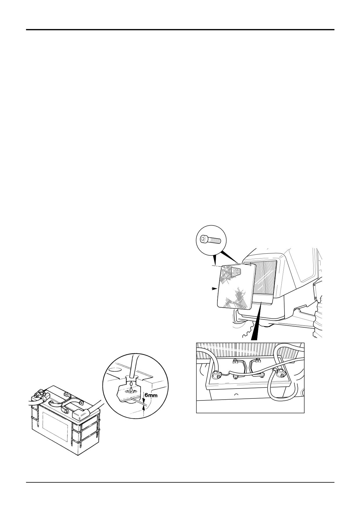
Remove the front grille A.
connecting or disconnecting the battery. When you have
installed the battery in the machine, wait five minutes before
3
Remove battery cell covers. Look at the level in each
connecting it up.
cell. The electrolyte should be 6 mm (1/4 in) above the
plates. Top up if necessary with distilled water or de-
First Aid - Electrolyte
ionised water.
Do the following if electrolyte:
GETS INTO YOUR EYES
Immediately flush with water for 15 minutes, always get
medical help.
IS SWALLOWED
Do not induce vomiting. Drink large quantities of water or
milk. Then drink milk of magnesia, beaten egg or vegetable
A
oil. Get medical help.
GETS ONTO YOUR SKIN
Flush with water, remove affected clothing. Cover burns with
a sterile dressing then get medical help.
5-3-4-3/1
399350
S260640
9803/3280
Issue 1
Section 3
Routine Maintenance
Section 3
21 - 3
Battery
21 - 3
Battery Isolator
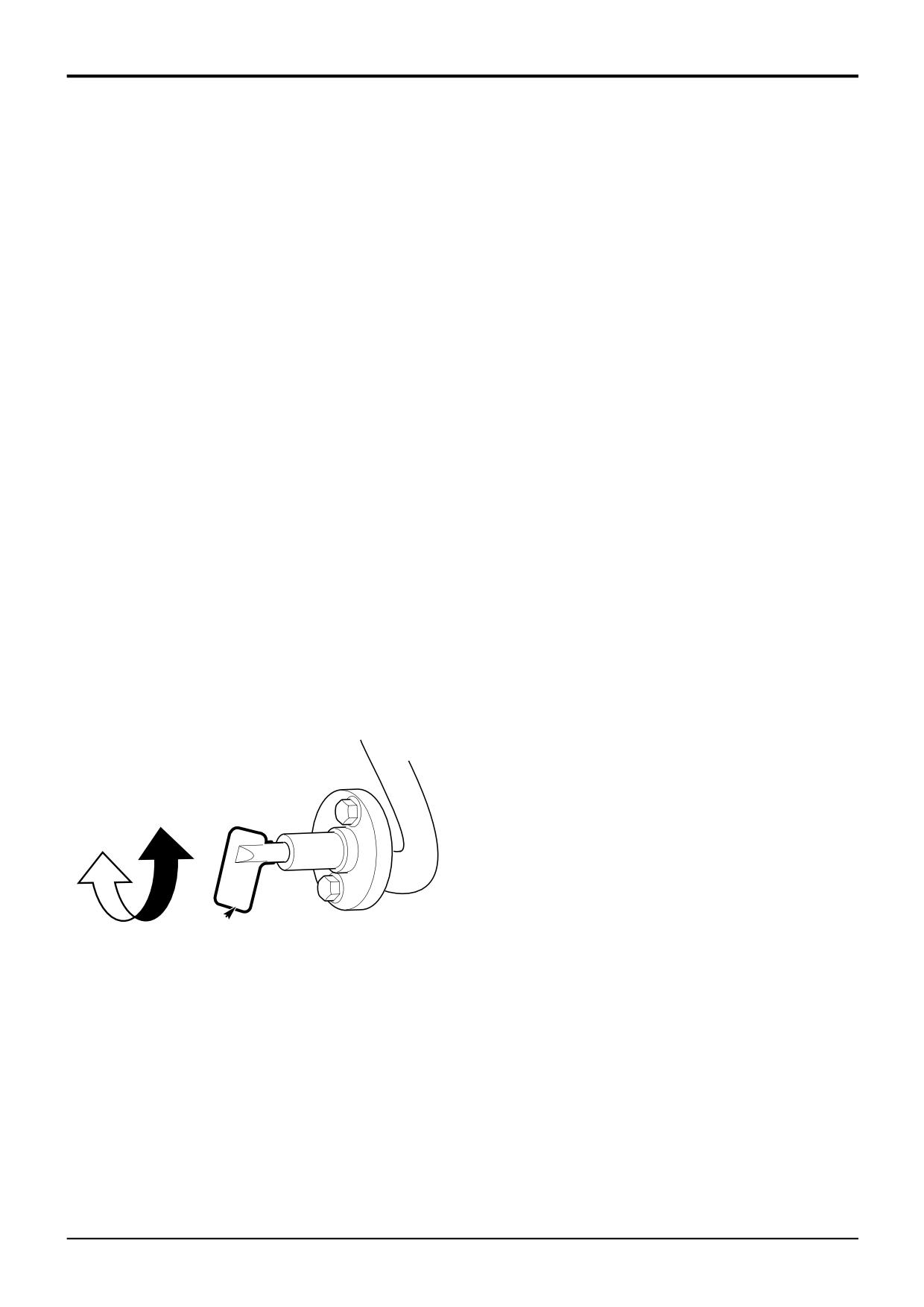
To disconnect the battery from the machine electrics a
battery isolator has been fitted.
! CAUTION
Except in an emergency, do not use the battery isolator
to switch OFF the engine. Failure to comply may result in
damage to the electrical circuits.
INT-3-2-13
At the end of a working cycle or if the machine is being left
unattended, provided the lights are not required, the battery
must be isolated. Before attempting to start the engine or
use the machine electrics the battery isolator key must be
fitted and switched on.
1
To isolate the battery turn the battery isolator key A in
an anti-clockwise direction B and remove. Keep the key
in a safe place and available for when the machine is
next required.
2
To connect the battery insert the key A and turn in a
clockwise direction C.
! CAUTION
Before carrying out arc welding on the machine
disconnect the battery and alternator to protect the
circuits and components.
The battery must still be disconnected even if the battery
isolator is fitted.
INT-3-1-13
B
C
A
A323611
9803/3280
Issue 1
Section 3
Routine Maintenance
Section 3
23 - 1
Hydraulic Oil Cooler
23 - 1
Cleaning the Tubes/Fins
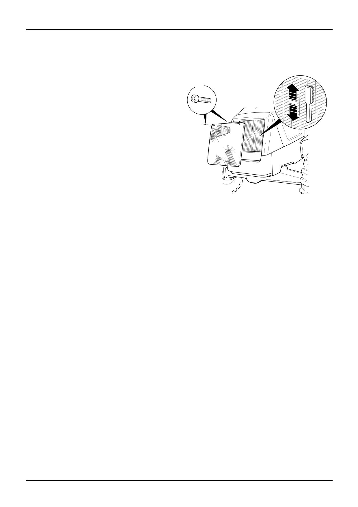
The hydraulic oil cooler is in front of the engine radiator. If
the hydraulic oil cooler tubes/fins get clogged (by dirt and
flies etc) the radiator and cooler will be less efficient.
A
1
Park the machine on firm level ground, engage the
parking brake and set the transmission to neutral. Raise
and block the loader arms. Lower the backhoe to the
ground and stop the engine.
2
Unscrew bolts A. Lift off the radiator grille.
3
Brush off all debris from the cooler tubes and fins.
Make sure the loosened material is brushed out of the
cooler enclosure.
4
Refit the radiator grille. Tighten bolts A evenly.
399360
9803/3280
Issue 1
Section 3
Routine Maintenance
Section 3
25 - 1
Stabiliser Legs (Sideshift Machines only)
25 - 1
Wear Pads
Wear Pad Adjustment
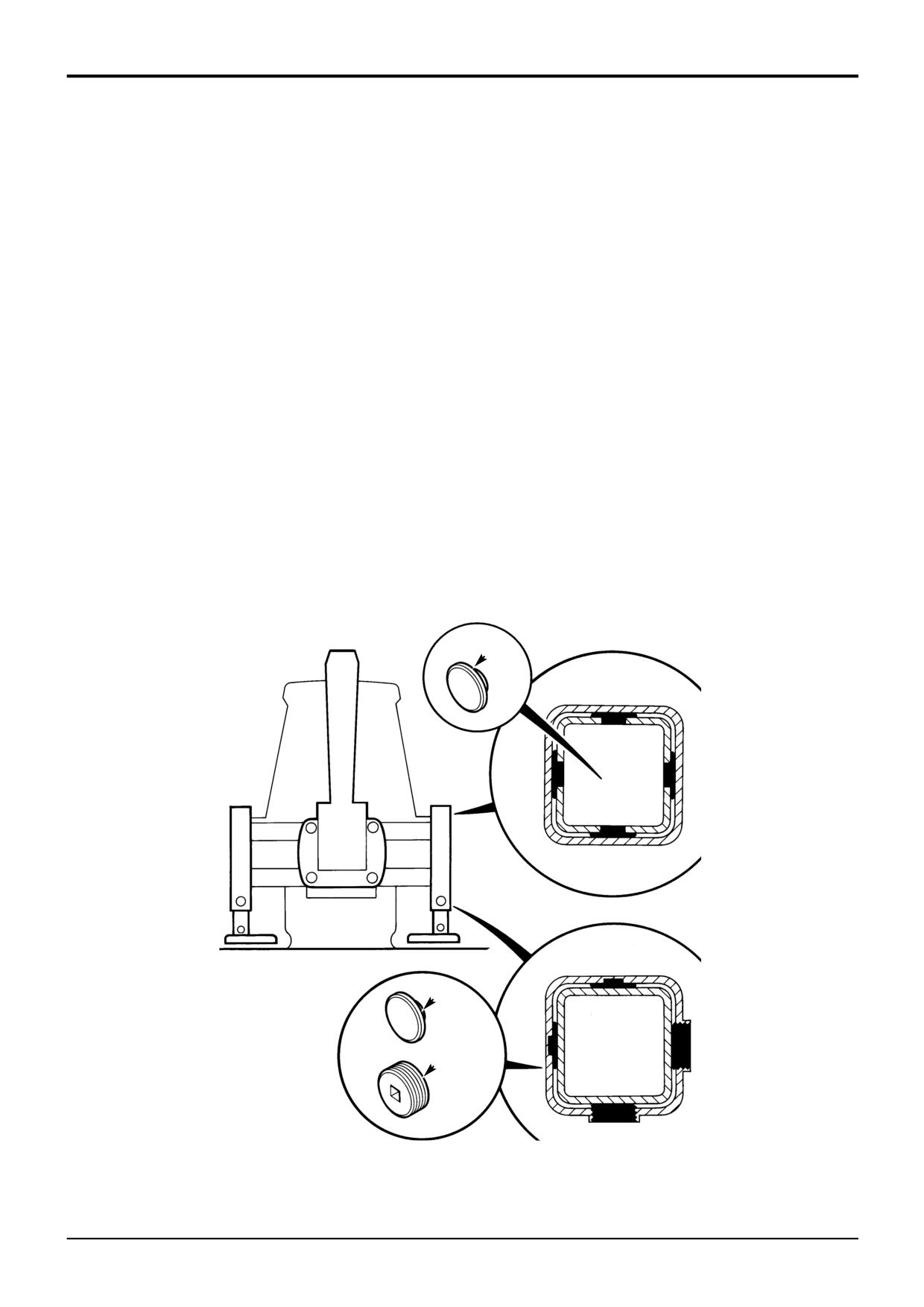
The wear pads support and guide the inner leg section. They
Note: It is very important that the wear pads are adjusted
ensure that during extension and retraction the inner leg is
at the correct service intervals, as the inner leg could
kept central and has a minimum amount of ‘float’.
contact the outer leg and scoring could occur. Scoring
will dramatically reduce wear pad life.
Upper wear pads A (4 off) are fitted to the top of the inner
leg as shown. The upper pads are available in 3 sizes and
Remove and clean away all debris that may have built up in
are colour coded; 5mm (green); 6mm (red) and 7mm (blue).
stabiliser cavities.
Lower wear pads comprise adjustable pads B (2 off) and
fixed pads C (2 off).
As a guide, there should be approximately 1mm (0.039 in.)
float between the stabiliser inner and outer leg.
When pads A and C have worn to a minimum thickness of
0.5 mm (0.020 in.) they must be replaced with new ones. To
Before adjusting the clearance make sure that the leg is
replace the pads, the stabiliser inner leg must be removed
raised clear of the ground but not fully retracted.
(contact your JCB Distributor).
To adjust the clearance, screw pad B fully in until it just
It is important to note that lower pads C are designed to
touches the inner leg and then back the pad off by one
take most of the ‘loading’ during stabiliser leg operation, as
quarter of a turn.
a consequence these pads must be checked regularly for
wear.
Note: Over-tightening the adjustable pad B will lock the pad
in position, it will not be possible to back the pad off. If this
When replacing pads, it is recommended that the complete
should happen, operate the stabiliser leg as normal but be
lower set of pads are replaced (items B and C). The top
aware that pads B and C will wear more rapidly.
pads should be inspected and replaced as required.
A
C
B
S273120
9803/3280
Issue 1