JCB 3CX, 4CX, 214e, 214, 215, 217 & VARIANTS Backhoe Loader. Service Manual - page 5
Section B
Body & Framework
Section B
30 - 2
Air Conditioning
30 - 2
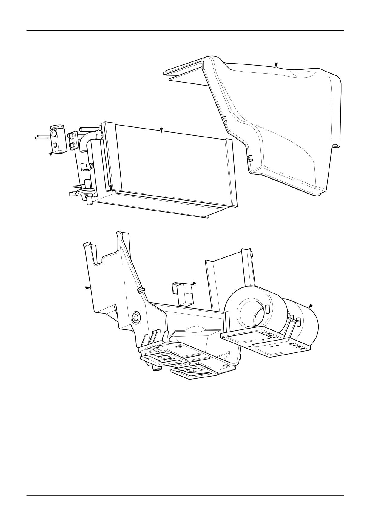
HVAC/Air Conditioning Unit
- Removal and Replacement
Note: Before removing the HVAC/Air Conditioning Unit,
discharge the system. Refer to Service Procedures, Air
Conditioning - Refrigerant Charging and Discharging.
The HVAC/air conditioning unit is located in the cab beneath
the right hand side console. To access the unit the side
console must first be removed. With the right hand side
console removed as shown it is possible to gain access to
the following:
HVAC Unit Top Cover
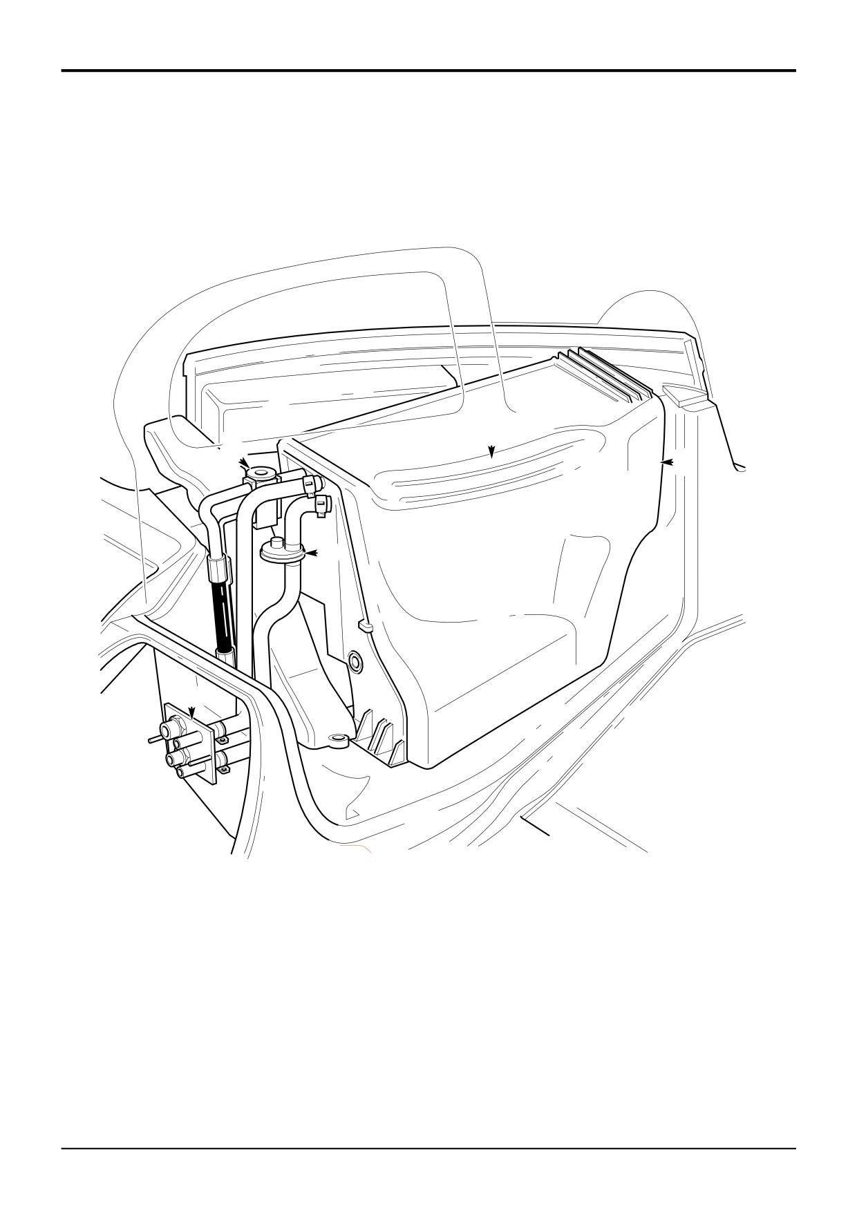
Binary Pressure Switch
Water Valve
The HVAC unit top cover must also be removed to access
the following components:
Freeze Protection Thermostat
Blower Unit
Resistor
Heat Exchangers (Heater and Evaporator)
Note: When removing components or hoses, retain any
lubricant within the component/hose and replenish the
system with the same amount of clean lubricant (PAG Oil).
Removal
Removal of the HVAC unit will require the assistance of a
refrigeration engineer or suitably trained person since the
refrigerant needs to be drained from the system.
1
Disconnect the battery.
2
Loosen and remove the side console screws and
remove the side console.
3
Remove the spring clips (8 off) securing the HVAC unit
top cover and carefully remove the HVAC top cover.
! WARNING
The air conditioning system is a closed loop system and
contains pressurised refrigerant. No part of the system
must be disconnected except by a refrigeration engineer
or suitably trained person. You can be severely
frostbitten or injured by escaping refrigerant
4-3-4-1/2
4
Drain the refrigerant from the unit and remove all
pipe work (refrigerant and air) which will prevent the
unit from being withdrawn from the machine. Check
around the top of unit, rear, bottom and right side.
5
Disconnect the pipe and electrical connections
adjacent to the bulkhead plate X.
6
Remove the screws securing the HVAC unit housing to
the cab and carefully withdraw the HVAC unit.
Replacement is the reverse of the removal procedure.
9803/3280
Issue 1
Section B
Body & Framework
Section B
30 - 3
Air Conditioning
30 - 3
R
S
T
V
X
W
A401270
Component Key:
R HVAC Unit Top Cover
S Heat Exchanger (Heater and Evaporator)
T Expansion Valve
V Freeze Protection Thermostat
W Blower Unit
X HVAC Unit Housing
9803/3280
Issue 1
Section B
Body & Framework
Section B
30 - 4
Air Conditioning
30 - 4
Blower Unit - Removal and Replacement
Evaporator Matrix
- Removal and Replacement
The blower W is located inside the HVAC/air conditioning
unit and can be removed without having to remove the HVAC
Note: Before removing the Evaporator Matrix, discharge
unit from the machine.
the system. Refer to Service Procedures, Air
Conditioning - Refrigerant Charging and Discharging.
The only user-serviceable part is the resistor which
determines the blower motor speed. Other faults, excluding
The evaporator matrix S is located inside the HVAC/air
wiring faults, necessitate the replacement of the blower unit
conditioning unit and can be removed without having to
complete.
remove the HVAC unit from the machine.
Resistor replacement requires the removal of the blower unit
Removal
as follows:
Removal of the evaporator matrix will require the assistance
Removal
of a refrigeration engineer or suitably trained person since
the refrigerant needs to be drained from the system.
1
Disconnect the battery.
1
Disconnect the battery.
2
Gain access to the HVAC unit by removing the right
hand side console and remove the HVAC unit top cover,
2
Gain access to the HVAC unit by removing the right
refer to HVAC/Air Conditioning Unit - Removal and
hand side console and remove the HVAC unit top
Replacement Steps 2 and 3.
cover, refer to HVAC/Air Conditioning Unit - Removal
and Replacement Steps 2 and 3.
3
Disconnect the electrical connections to the blower.
3
Unclip the thermostat sensor wire from the
4
Remove the screws securing the blower unit to
evaporator and gently remove the wire from
the HVAC unit housing.
between the fins.
5
Carefully withdraw the blower from the HVAC unit.
!
WARNING
6
To remove the resistor, disconnect the electrical
The air conditioning system is a closed loop system and
connections and unscrew the resistor.
contains pressurised refrigerant. No part of the system
must be disconnected except by a refrigeration engineer
Replacement is the reverse of the removal procedure.
or suitably trained person. You can be severely
frostbitten or injured by escaping refrigerant
4-3-4-1/2
Freeze Protection Thermostat
4
Drain the refrigerant from the unit and remove all
- Removal and Replacement
pipe work (refrigerant and air) which will prevent the
unit from being withdrawn from the machine. Check
The Thermostat V monitors the external temperature of the
around the top of unit, rear, bottom and right side.
evaporator and is located inside the HVAC/air conditionig
unit.
5
Carefully lift the evaporator matrix complete with
expansion valve T from the housing, bearing in mind
Removal
that a certain amount of resistance will be met due to
the stiction from the sealing putty.
1
Disconnect the battery.
Replacement is the reverse of the removal procedure.
2
Gain access to the HVAC unit by removing the right
hand side console and remove the HVAC unit top cover,
refer to HVAC/Air Conditioning Unit - Removal and
Replacement Steps 2 and 3.
3
Unclip the sensor wire from the evaporator and
gently remove the wire from between the fins.
4
Disconnect the electrical connections to the thermostat.
5
Remove the screws securing the thermostat to
the HVAC unit housing.
Replacement is the reverse of the removal procedure.
9803/3280
Issue 1
Section B
Body & Framework
Section B
30 - 5
Air Conditioning
30 - 5
R
T
S
W
V
X
A401280
Component Key:
R A/C Controls
S Expansion Valve
T Re-circ Air Inlet
V Water Valve
W HVAC Unit
X Bulkhead Plate
9803/3280
Issue 1
Section B
Body & Framework
Section B
30 - 6
Air Conditioning
30 - 6
Binary Pressure Switch
- Removal and Replacement
The pressure switch is located adjacent to the expansion
valve S on the HVAC/air conditioning unit, beneath the right
hand side console.
! WARNING
Goggles and rubber gloves must be worn when pressure
switches are removed or fitted. A small amount of
refrigerant is released which can be harmful to the skin
and eyes.
BF 1-10
Removal
1
Disconnect the battery.
2
Gain access to the HVAC unit by removing the right
hand side console, refer to HVAC/Air Conditioning
Unit - Removal and Replacement Step 2.
3
Disconnect the electrical connections and unscrew the
pressure switch.
Replacement
1
Screw the pressure switch into the pressure switch port
and torque tighten sufficiently to form a gas-tight seal.
2
Run the air conditioning and check the pressure
switches for leaks. If any leaks are found, tighten the
pressure switch further until the leaking stops.
9803/3280
Issue 1
Section B
Body & Framework
Section B
35 - 1
Loader Arms
35 - 1
A
X
B
D
E
T
R
U
F
G
S
H
Y
K
L
Z
S265931
9803/3280
Issue 1
Section B
Body & Framework
Section B
35 - 2
Loader Arms
35 - 2
Removal and Replacement
Removal
!
WARNING
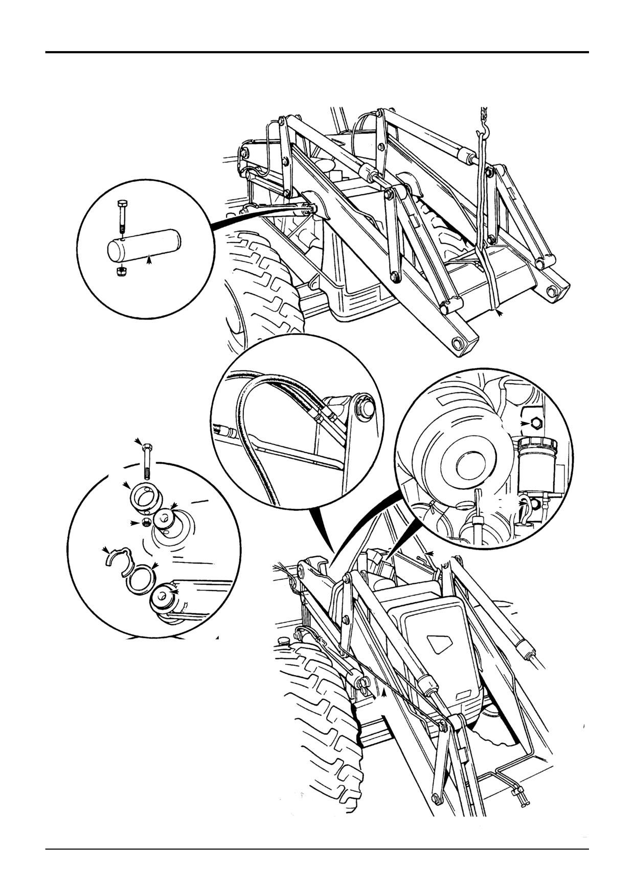
1
Park the machine on firm level ground. Engage the
The loader arm interlevers are potentially dangerous,
parking brake and set the transmission to neutral.
when pivoting about their centre they form a 'scissor'
point with the loader arm. Make sure the interlevers are
2
Remove loader end attachment (such as a shovel) if
securely blocked when working in the loader arm area.
fitted. If the attachment is hydraulically operated,
BF 2-1
disconnect attachment hoses and plug/cap
14
Secure the interlever lever linkage as shown at Z,
immediately. Vent residual hydraulic pressure prior to
otherwise with level link pivot pin L removed, the
removing hoses by operating the control levers with the
engine switched off.
interlever linkage could pivot about its centre and
cause injury and/or damage.
! WARNING
15
Remove pivot pin L (use slide hammer kit, service tool
DO NOT work under raised loader arms unless they are
993/68100).
adequately supported by stands and/or slings.
BF 3-1
16
Repeat steps 13 to 15 for the opposite level link pivot
pin.
3
Remove the engine panels, refer to Section 3 Routine
Maintenance - Engine Panels.
17
Remove bolt T and retaining ring R.
4
Raise the loader arms to give access to the lift ram
18
Remove pivot pin U (use slide hammer kit, service tool
pivot pins A.
993/68100)
5
Sling the loader arms as shown at X. Make sure that
19
Repeat steps 17 and 18 for the opposite loader arm
the slings are taut and therefore holding the weight of
pivot pin.
the loader arms.
20
When all four pivot pins have been removed, carefully
6
Switch off the engine and vent residual hydraulic
reverse the machine clear of the loader arms
pressure from the loader end by operating the loader
controls back and forth several times.
Replacement
7
Remove the lift ram pivot pins A.
Replacement is a reversal of the removal sequence.
Note: Care must be taken when removing the lift ram pivot
Fit pivot pins with the extraction hole on the outside of the
pin, once the pin is removed the ram will drop. Either hold
machine.
the ram using a sling or have a second person hold the ram
before removing the pin.
Check operation of loader shovel reset switch (if fitted).
8
Lower the loader arms to the ground using the slings, it
Apply grease to all mainframe bores.
may be necessary to retract the lift rams to enable the
loader arms to rest fully on the ground. Make sure the
Apply rust inhibiting oil to all pivot pins.
lift rams do not foul when retracted.
If fitting new liner bearings, assemble with a close fitting
9
Make sure residual hydraulic pressure has been vented.
shouldered mandrel to ensure minimum ovality.
Disconnect the shovel ram and auxiliary (if fitted) hoses,
shown at B. Plug and cap the hoses immediately.
10
Disconnect the electrical connections (not shown) to
the loader shovel reset switch (if fitted).
11
Remove pivot pin retaining bolts D, E, F and G.
12
Sling the loader arms as shown at Y. Make sure that
the sling is wrapped around the loader arms only and
not the level links.
13
Remove klipring H and shim K.
9803/3280
Issue 1
Section B
Body & Framework
Section B
36 - 1
Stabiliser Legs
36 - 1
G
F
D
C
E
A B
S261790
S216810
9803/3280
Issue 1
Section B
Body & Framework
Section B
36 - 2
Stabiliser Legs
36 - 2
Removal and Replacement
- (Centremount Machines)
Removal
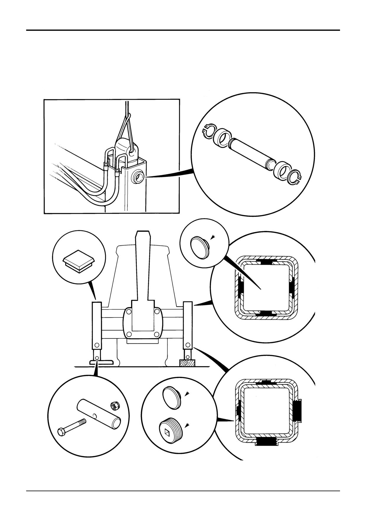
5
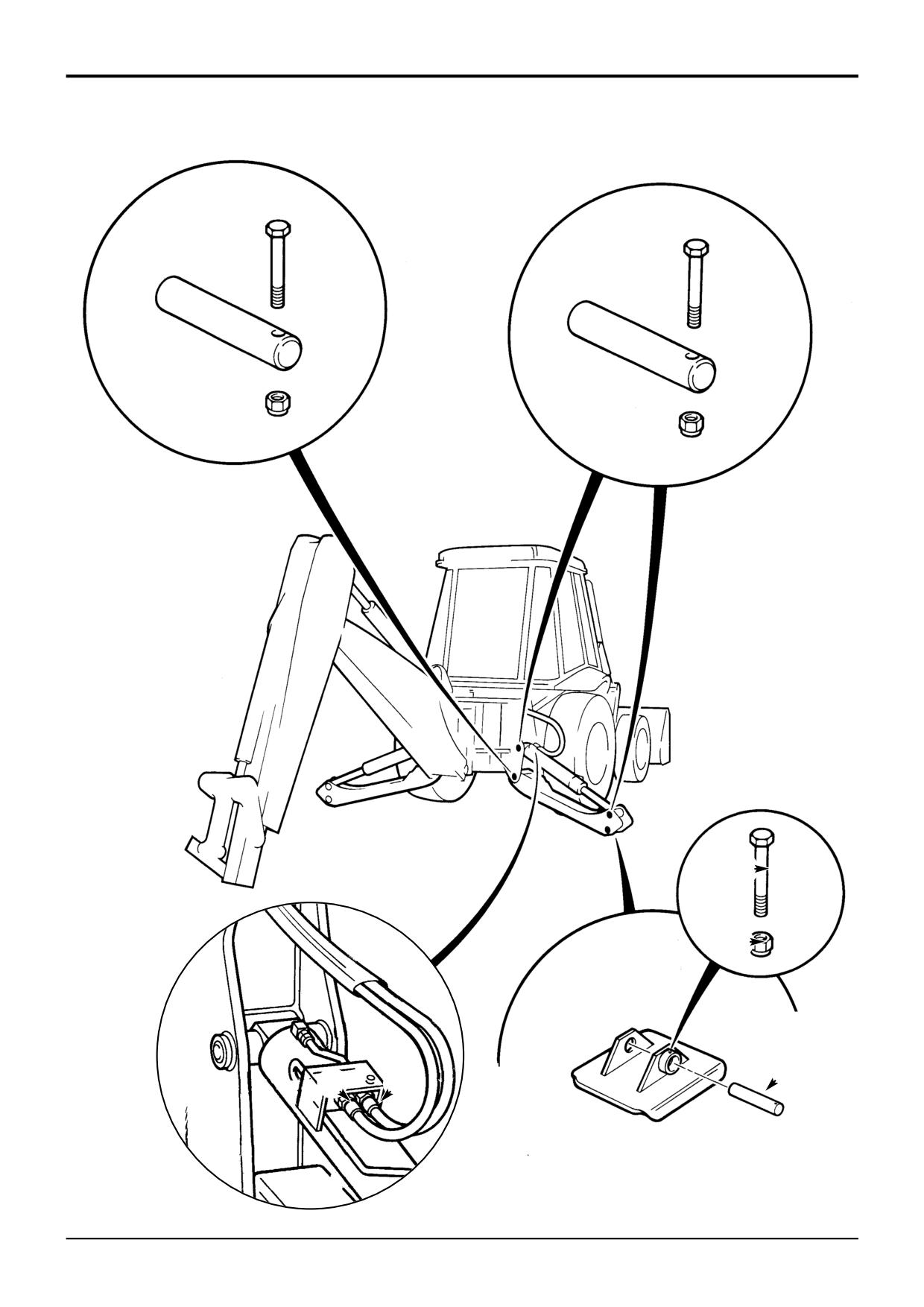
Remove the stabiliser leg:
1
Park the machine on firm level ground, engage the
parking brake and set the transmission to neutral.
Lower the backhoe and loader end to the ground and
! CAUTION
stop the engine.
The stabiliser leg is heavy. It is recommended that the
stabiliser leg is removed with the assistance of a sling
2
Lower the stabiliser legs to the ground.
and suitable lifting appliance.
BF 2-6
DANGER
a Wrap a suitable sling around the stabiliser leg,
Hydraulic Pressure
make sure that the weight of the leg is supported
Hydraulic fluid at system pressure can injure you. Before
by the sling.
disconnecting or connecting hydraulic hoses, stop the
engine and operate the controls to release pressure
b Remove the stabiliser leg pivot pin retaining nut
trapped in the hoses. Make sure the engine cannot be
and bolt, drive out the stabiliser leg pivot pin, as
started while the hoses are open.
shown at G.
INT-3-1-11/1
c Remove the stabiliser leg.
3
Make sure the engine is switched off, vent residual
hydraulic pressure by moving the backhoe and
stabiliser control levers back and forth.
Replacement
Note: If a check valve is fitted on the ram, the system will
not vent. Extreme caution must be used when releasing
Replacement is a reversal of the removal sequence.
hydraulic connections - release the connections one turn
and allow the pressure to dissipate.
Use suitable lifting appliances to locate the stabiliser ram
and the stabiliser leg.
4
Remove the stabiliser ram:
After replacing or fitting the stabiliser leg, connect the
a Carefully disconnect hydraulic hoses A and B from
hydraulic pipes, make sure that the ram and leg operate
the stabiliser hydraulic ram, label the hoses before
freely and do not foul.
removing (as an aid to assembly). Release the
connections slowly.
b If a stabiliser foot is fitted, remove nut C and
retaining bolt D. Drive out the foot retaining pin E.
! CAUTION
The ram is heavy. It is recommended that the ram is
removed with the assistance of a sling and suitable
lifting appliance.
BF 2-4
c Wrap a suitable sling around the stabiliser ram,
make sure that the weight of the ram is supported
by the sling.
d Remove the ram pivot pin retaining nut and bolt,
drive out the ram pivot pin as shown at F.
e Remove the stabiliser ram.
9803/3280
Issue 1
Section B
Body & Framework
Section B
36 - 3
Stabiliser Legs
36 - 3
A
C
B
S271850
9803/3280
Issue 1
Section B
Body & Framework
Section B
36 - 4
Stabiliser Legs
36 - 4
Removal and Replacement
- (Sideshift Machines)
Removal
1
Park the machine on firm level ground. Engage the
parking brake and set the transmission to neutral.
2
Lower the loader shovel to the ground.
3
Make sure that the backhoe assembly is set central to
the mainframe as shown. If necessary 'sideshift' the
backhoe into a central position.
4
Remove the stabiliser foot and ram, refer to Section E
Hydraulic Rams, Removal and Replacement
-
Stabiliser Ram.
5
Remove the inner leg:
a Locate a suitable jack underneath the
inner leg.
b Use the jack to lift the inner leg until the top wear
pads A protrude from the top of the outer leg
section.
c Remove the wear pads and attach suitable lifting
gear through the wear pad locating holes.
d Use suitable lifting equipment, lift the inner leg
clear.
Replacement
Replacement is a reversal of the removal sequence.
Select suitable size upper pads A to achieve a maximum
permissible float of 1mm (0.039 in.).
Make sure that the bottom pads C are held in position
before guiding the inner leg into position. If the lower pads
are not secured then the inner leg could dislodge the pads
during assembly.
When the inner leg is in position adjust the bottom pads,
refer to Section 3 Stabiliser Legs - Wear Pad Adjustment.
Apply a grease such as JCB slew grease (part number
4003/1601) to the threads of pad B.
9803/3280
Issue 1
Section B
Body & Framework
Section B
37 - 1
Kingpost
37 - 1
Removal and Replacement
72
m
14
71
Item 14
57
Item 15
om Pivot Bearing - 15ft 6in / 17ft Backhoe)
(Boom Pivot Bearing - 14ft Backhoe)
(Kingpost Pivot Bearing)
A261800
A252870
A252880
17
7
11
8
15
9
10
5
17
6
4
12
6
13
14
17
15
2
17
16
13
14
3A
16
1
3A
S254893
3
9803/3280
Issue 1
Section B
Body & Framework
Section B
37 - 2
Kingpost
37 - 2
Removal and Replacement
Removal
Replacement
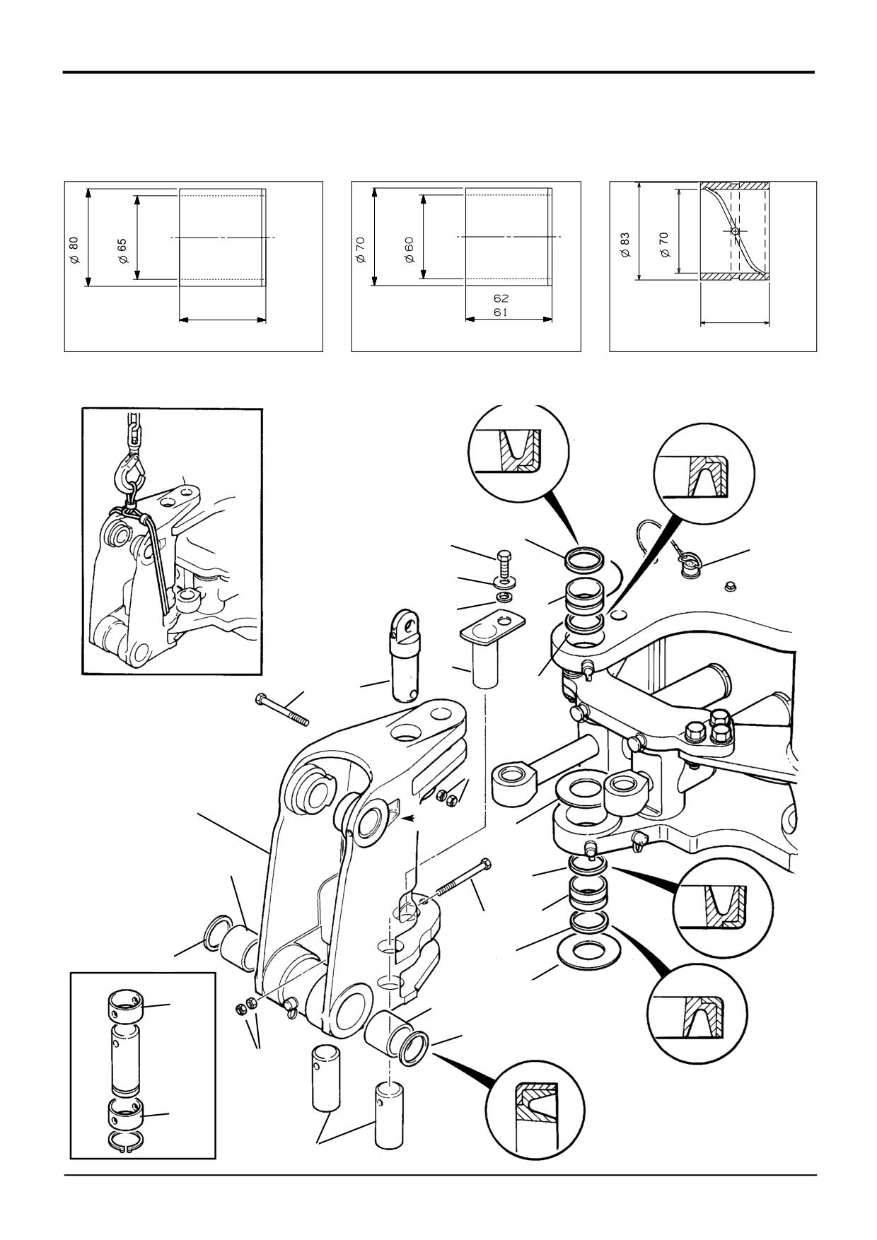
1
Slew the kingpost to the centre and remove the boom
Replacement is generally a reversal of the removal
and dipper.
procedures, however note the following:
! WARNING
To assist with the identification of 15ft 6in and 17ft
Hydraulic fluid at system pressure can injure you. Before
disconnecting or connecting hydraulic hoses, stop the
centremount kingposts the number 6 is stamped on the
engine and operate the controls to release pressure
kingpost to identify 60mm diameter bores.
trapped in the hoses. Make sure the engine cannot be
started while the hoses are open.
Check for and remove any burrs and sharp edges on both
INT-3-1-11/1
housing bore, bearing and pivot pin to minimise assembly
damage.
2
Make sure that the slew lock pivot pin 11 is in its
stowage position (i.e. not fitted in the ‘slew lock’
If necessary, use oil or suitable lubricant to facilitate
position.
pressing-in bearing - to minimise scoring of mating face.
3
Working from the base up, disconnect the backhoe
Bearings 14 and 15 have ‘lead-in’ diameters (noticeable with
hydraulic hoses, before disconnecting the hoses make
a slight step), always install the smaller diameter first into the
sure that they are labelled (to assist with reassembly).
pivot bore.
4
Plug and cap all open hydraulic connections to prevent
Thrust washers 13 come in different sizes to allow for
ingress of dirt and loss of hydraulic fluid.
variations of castings.
5
Remove thin nuts 1 (2 off per pivot pin) and remove
Make sure that the boom base liner bearings 14 are fully
pivot pin retaining bolt 2 (2 off).
engaged in the boom base pivot bores. There must be a
recess of 5mm (3/16 inch) to allow for installation of the
6
Remove the slew ram (eye end) pivot pins 3 (2 off) and
seals 16.
bearing liners 3A.
If fitting new liner bearings, assemble with a close fitting
7
Attach suitable lifting straps to the kingpost assembly.
shouldered mandrel. Refer to liner bearing sizes on the
Note that the weight of the kingpost casting is
illustration (nominal figures given).
approximately 130 kg (287 lbs).
Make sure that the liner bearings 15 are fully engaged in the
8
Remove the boom lock assembly (see Boom Lock
kingpost pivot bores. There must be a recess of 6mm (1/4
Removal and Replacement in Controls, section D).
inch) to allow for installation of the seals 17.
9
Remove thin nuts 4 (2 off) and remove retaining bolt 5.
If a new kingpost casting has been installed, the boom lock
may need resetting, refer to the boom lock removal and
10
Remove the kingpost top pivot pin 6.
replacement procedures.
11
Remove bolt 7, washer 8, and spacer 9.
Seals 16 and 17 are lip seals, on reassembly make sure that
the seal lips face outward (shown in insets on the kingpost
12
Remove the kingpost bottom pivot pin 10.
pivot).
13
Remove the kingpost casting 12 from the rear frame
Make sure that thin lock nuts, items 1 and 4 are ‘just’ free
and thrust washers 13.
when locked into position.
Inspection
Make sure that all pivot bores and pivot pins are clean and
greased when assembling. When fully assembled, apply
Inspect the nickel bronze liner bearings 14 and 15 for signs
grease at each grease nipple before operating the machine.
of damage, wear, scores or nicks etc. Use a suitable
mandrel (manufactured locally) to facilitate removal of the
liner bearings.
To ensure the drift is manufactured to the correct size, the
liner bearing dimensions are shown on the illustration. Note
that the dimensions are NOMINAL figures only and must not
be used to manufacture the liner bearings.
9803/3280
Issue 1
Section B
Body & Framework
Section B
38 - 1
Boom and Dipper
38 - 1
E
G
F
B
H
J
L
A
C
D
9803/3280
Issue 1
Section B
Body & Framework
Section B
38 - 2
Boom and Dipper
38 - 2
Boom - Removal and Replacement
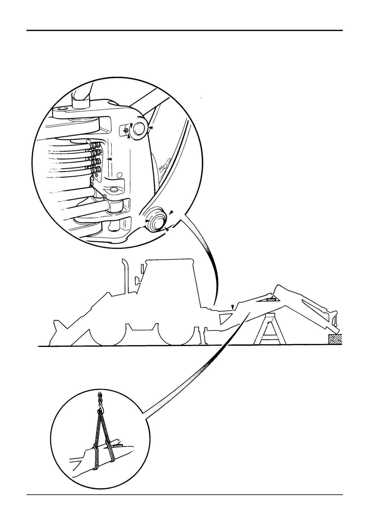
Removal
Replacement
The procedures describe the removal of the boom with the
! WARNING
boom and dipper rams still installed. If required, these items
Hydraulic Fluid
can be removed separately before removing the boom, refer
Fine jets of hydraulic fluid at high pressure can penetrate
to the appropriate removal and replacement procedure.
the skin. Do not use your fingers to check for hydraulic
fluid leaks. Do not put your face close to suspected
1
Remove the backhoe bucket and place the backhoe in
leaks. Hold a piece of cardboard close to suspected
the position shown at A.
leaks and then inspect the cardboard for signs of
hydraulic fluid. If hydraulic fluid penetrates your skin, get
2
Lower the stabilisers.
medical help immediately.
INT-3-1-10/1
3
Stop the engine and disconnect the battery (to prevent
the engine being started).
Replacement is generally a reversal of the installation
procedure.
4
Operate the backhoe control levers back and forth
several times to release pressure trapped in the
The boom pivot pin G must be retained using two M12 thin
hydraulic hoses.
nuts. Fit the first thin nut with zero torque, fit the second thin
nut and torque to 98Nm (72 lbf ft).
! DANGER
When fitting the boom to the kingpost assembly, make sure
Hydraulic Pressure
that spacers J are refitted in their original positions.
Hydraulic fluid at system pressure can injure you. Before
disconnecting or connecting hydraulic hoses, stop the
Replace all pivot pin seals as required.
engine and operate the controls to release pressure
trapped in the hoses. Make sure the engine cannot be
started while the hoses are open.
INT-3-1-11/1
5
Disconnect the hydraulic hoses from the bulkhead plate
B. Always label hydraulic hoses before disconnecting
them, this will ensure that they are correctly
reconnected. Plug and cap all hose open ends to
prevent ingress of dirt and loss of hydraulic fluid.
6
Remove the dipper, see Dipper - Removal and
Replacement.
7
Wrap a sling around the boom as shown at D. Make
sure the weight of the boom is held by the sling before
removing pivot pins etc.
8
Place a suitable support underneath the boom ram C.
9
Remove two thin nuts E, bolt F and pivot pin G.
10
Remove heavy duty circlip H, spacers J (one fitted each
side) and pivot pin L. Mark the spacers so that they can
be replaced in the same positions.
11
Hoist the boom clear of the kingpost assembly.
9803/3280
Issue 1
Section B
Body & Framework
Section B
38 - 3
Boom and Dipper
38 - 3
F
G
E
J
K
H
B
A
C
D
L
S266170
9803/3280
Issue 1
Section B
Body & Framework
Section B
38 - 4
Boom and Dipper
38 - 4
Dipper - Removal and Replacement
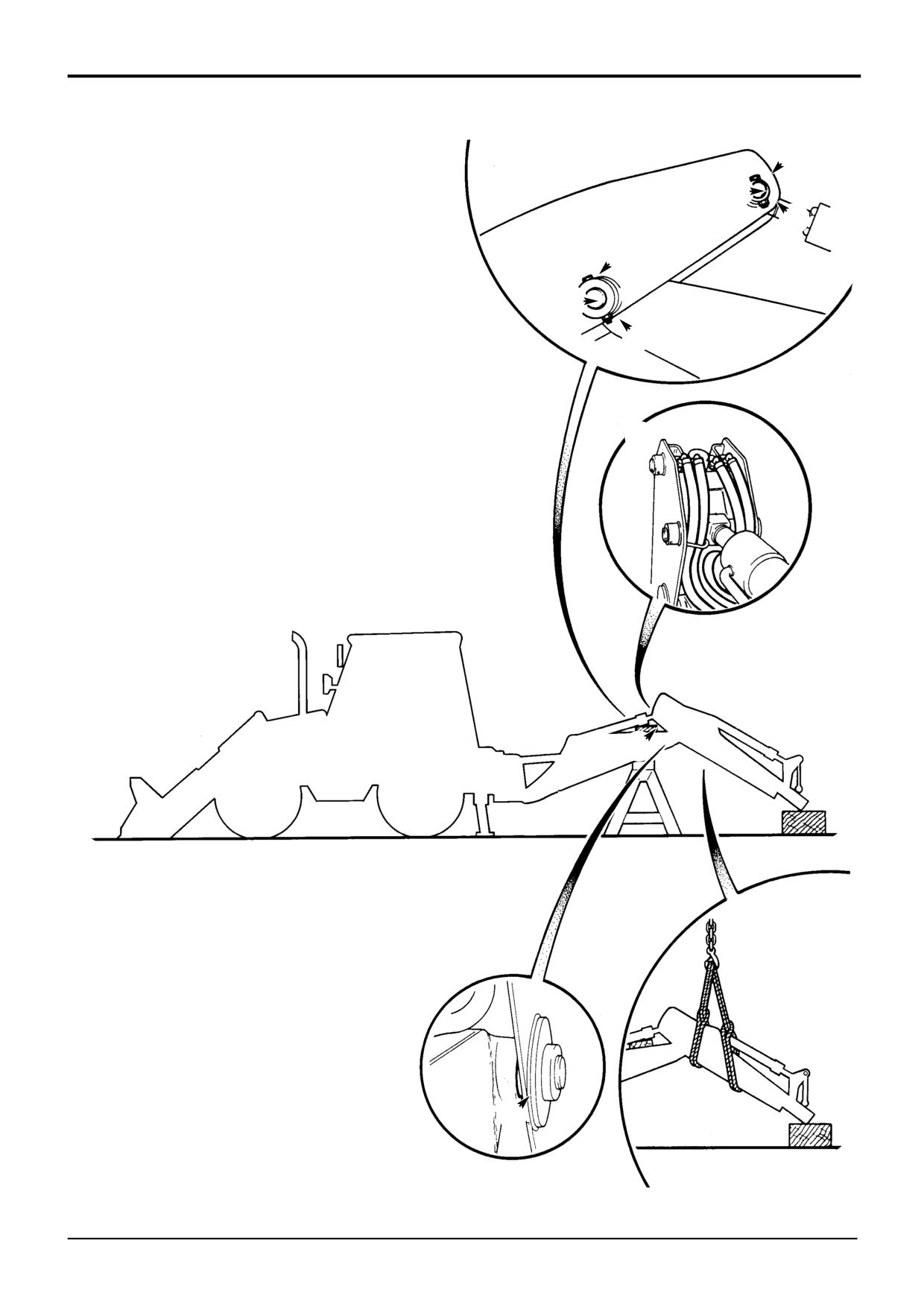
Removal
Replacement
The procedures describe the removal of the dipper with the
! WARNING
extradig (if fitted) and the bucket ram still installed. If
Hydraulic Fluid
required, these items can be removed separately before
Fine jets of hydraulic fluid at high pressure can penetrate
removing the dipper, refer to the appropriate removal and
the skin. Do not use your fingers to check for hydraulic
replacement procedure.
fluid leaks. Do not put your face close to suspected
leaks. Hold a piece of cardboard close to suspected
1
Remove the backhoe bucket and place the backhoe in
leaks and then inspect the cardboard for signs of
the position shown at A.
hydraulic fluid. If hydraulic fluid penetrates your skin, get
medical help immediately.
2
Lower the stabilisers.
INT-3-1-10/1
3
Stop the engine and disconnect the battery (to prevent
the engine being started).
Replacement is generally a reversal of the installation
procedure.
4
Operate the backhoe control levers back and forth
several times to release pressure trapped in the
The boom to dipper pivot pin K must be retained using two
hydraulic hoses.
M12 thin nuts. Fit the first thin nut with zero torque, fit the
second thin nut and torque to 98Nm (72 lbf ft).
! DANGER
When fitting the dipper to the boom, make sure that shim,
Hydraulic Pressure
item L is installed as shown.
Hydraulic fluid at system pressure can injure you. Before
disconnecting or connecting hydraulic hoses, stop the
Replace all pivot pin seals as required.
engine and operate the controls to release pressure
trapped in the hoses. Make sure the engine cannot be
started while the hoses are open.
INT-3-1-11/1
5
Disconnect the hydraulic hoses, as shown at B. Always
label hydraulic hoses before disconnecting them, this
will ensure that they are correctly reconnected. Plug
and cap all hose open ends to prevent ingress of dirt
and loss of hydraulic fluid.
6
Place a suitable support underneath the dipper ram as
shown at C.
7
Wrap a sling around the dipper as shown at D. Make
sure the weight of the dipper is held by the sling before
removing pivot pins etc.
8
Remove nut E, bolt F and pivot pin G.
9
Remove two thin nuts H, bolt J and pivot pin K.
Note: It is important to use two thin nuts, this arrangement
allows the pivot pin retaining bolt to be secured without
inducing a lateral tension.
10
Hoist the dipper clear of the boom.
9803/3280
Issue 1
Section B
Body & Framework
Section B
39 - 1
Hydraulic Tank
39 - 1
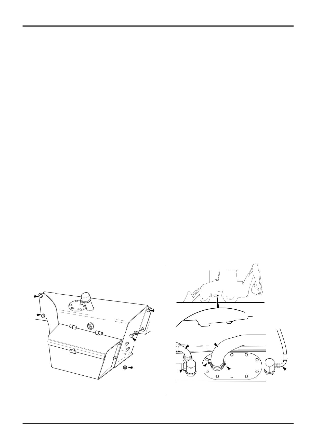
Removal and Replacement
Removal
Replacement
! WARNING
Replace the tank by reversing the removal procedure.
Make the machine safe before working underneath it.
If a new tank is being fitted, remove the tool box from the
Park the machine on level ground, lower the arms. Apply
old tank and fit to the new tank.
the parking brake, put the transmission in neutral and
stop the engine. Chock both sides of all four wheels.
Apply JCB Threadlocker and Sealer to drain plug B.
Disconnect the battery, to prevent the engine being
When refitting the suction hose G make sure it is correctly
*
started while you are beneath the machine.
fitted and phased on the tank spigot. There must be at least
GEN-1-2
12 mm (0.5 in) clearance between the hose and the gearbox
1
Operate the control levers to vent residual pressure.
casing. Phase the 2 clips F 180o apart.
2
Remove the filler cap and unscrew plug B to drain the
Refill with clean hydraulic oil as specified, refer to Section 3
tank.
Fluids, Lubricants, Capacities and Specifications.
3
Disconnect and plug the hydraulic hoses D from the
*
Operate the machine until the hydraulic oil reaches
rear of the tank.
operating temperature (50 oC, 122 oF). Stop the engine and
check for leaks.
* Note: Some machine variants may have different return
hose configurations at the tank to those illustrated. Be sure
Torque Setting
to disconnect all hoses.
Item
Nm
lbf ft
kgf m
* 4
Loosen the 2 clips F on the suction hose G. Pull off the
B
100
73.76
10.20
hose at the tank.
*
F
5
4
0.5
5
Support the tank, then unscrew mounting bolts E and
lift tank away from the machine.
E
E
E
G
E
D
B
F
F
D
D
A401540
9803/3280
Issue 2*
Section B
Body & Framework
Section B
40 - 1
Power Sideshift Ram
40 - 1
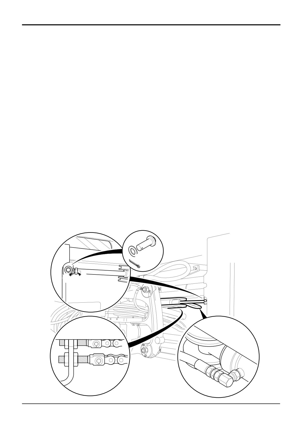
Removal and Replacement
Removal
Replacement
1
Park the machine on firm level ground, engage the
1
Locate the ram at one end with pin C. Adjust the ram
parking brake and set the transmission to neutral.
eye end so the the opposite end of the ram aligns with
Lower the loader arms to the ground.
mounting bracket.
2
Position the carriage in the central protruding travel
2
Secure the opposite end of the ram in position with pin
position at 150 mm (6 in) from end of the rail, rest the
C.
bucket on the ground and remove the starter key.
3
With a spanner on the rod end flats D adjust the rod so
3
Operate control levers to vent hydraulic pressure.
that the ram eye end engagement is equal at each end
of the ram. Lock eye ends in position with nut E.
4
Disconnect hydraulic hoses A and plug.
4
Reconnect the hydraulic hoses.
5
Disconnect all four chains at adjusters B and disengage
chains from ram pulleys.
5
Locate the chains around the applicable ram pulleys.
Reconnect chains and adjust as required, refer to
6
Remove pin C from one end and support the ram.
Service Procedures, Power Sideshift
- Chain
Adjustment.
7
Remove pin C from opposite end, withdraw ram.
C
E D
B
A
A326850
9803/3280
Issue 1
Section B
Body and Framework
Section B
50 - 1
Cab Panels
50 - 1
Removal and Replacement
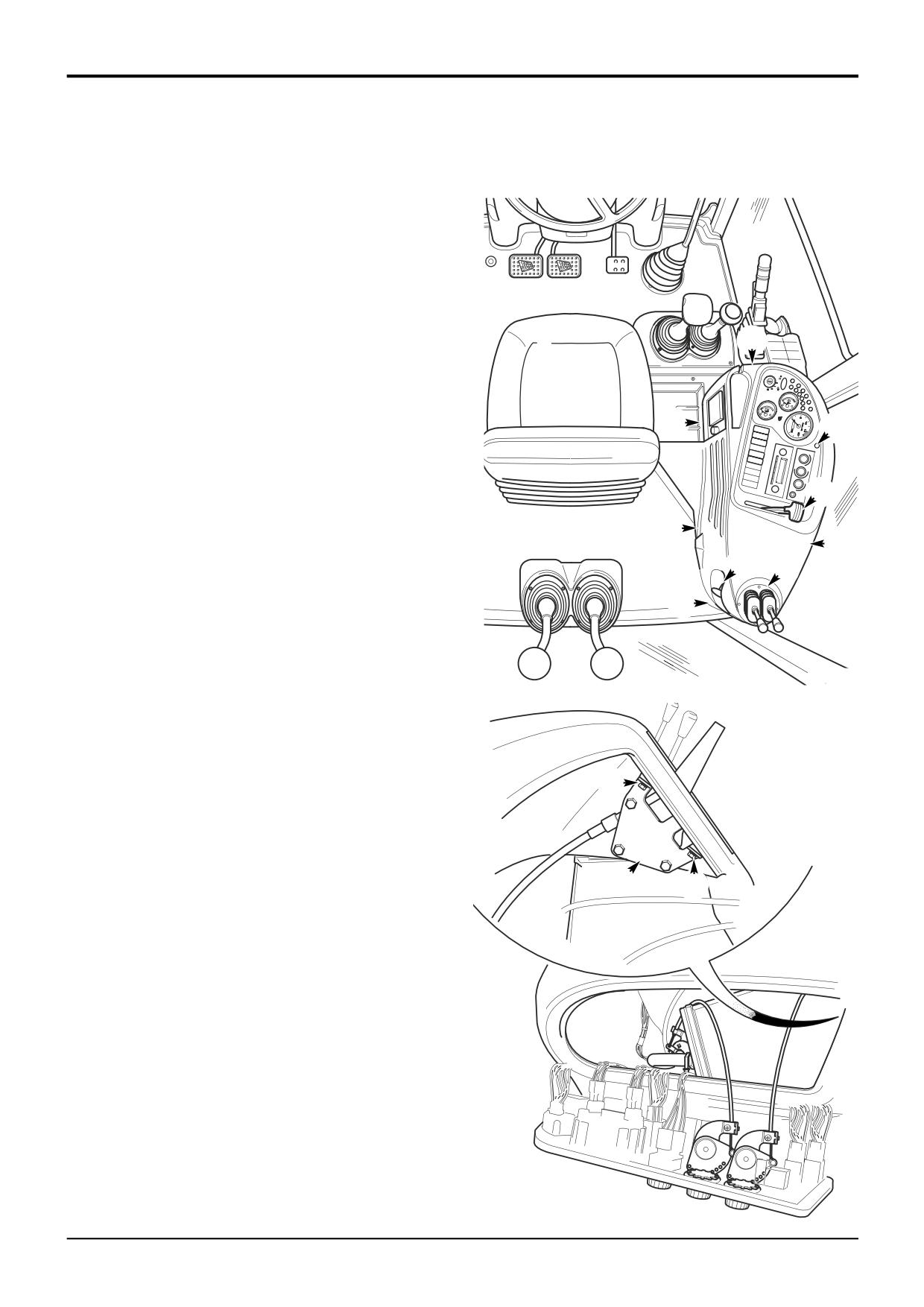
Side Console
Removal
1
Park the machine on firm level ground, apply the
parking brake. Lower the loader arms and excavator to
the ground, switch OFF the engine and remove the
starter key.
2
Disconnect the battery.
G
3
Working in the cab, remove the fixing A at the top of the
instrument panel and carefully lift the panel forward to
reveal the connections at the back as shown.
G
4
Disconnect the electrical connectors and heater
A
controls cables at the rear of the instrument panel, then
remove the instrument panel assembly clear of the side
console. Label the connectors and controls cables
B
before disconnecting to ensure correct replacement.
G
5
Remove the hand throttle lever knob B, remove the
G
screws C from the hand throttle lever and mounting
bracket assembly D inside the side console as shown.
F
E
Withdraw the handle through the slot in the panel.
G
6
Remove the screws from around the base of the
stabiliser control levers E, carefully withdraw the lever
assembly from the side console and disconnect the
control cables from the underside. Label each control
A394410
cable before disconnecting to ensure correct
replacement.
7
Unscrew the knob and lock nut from the boom lock
control F.
8
Remove the fixings G (5 off) securing the side console
C
panel at positions shown. Carefully lift up the rear
corner of the side panel over the boom lock control
outer sleeve, and then lift the side panel clear.
Replacement
D
C
Replacement is the reverse of the removal sequence.
Take care when removing/replacing the console panel to
ensure that harnesses do not become snagged and that no
other connections have been disturbed.
After re-fitting, operate the side console controls and check
they all function correctly.
A404670
9803/3280
Issue 1
Section B
Body and Framework
Section B
51 - 1
Cab Panels
51 - 1
Removal and Replacement
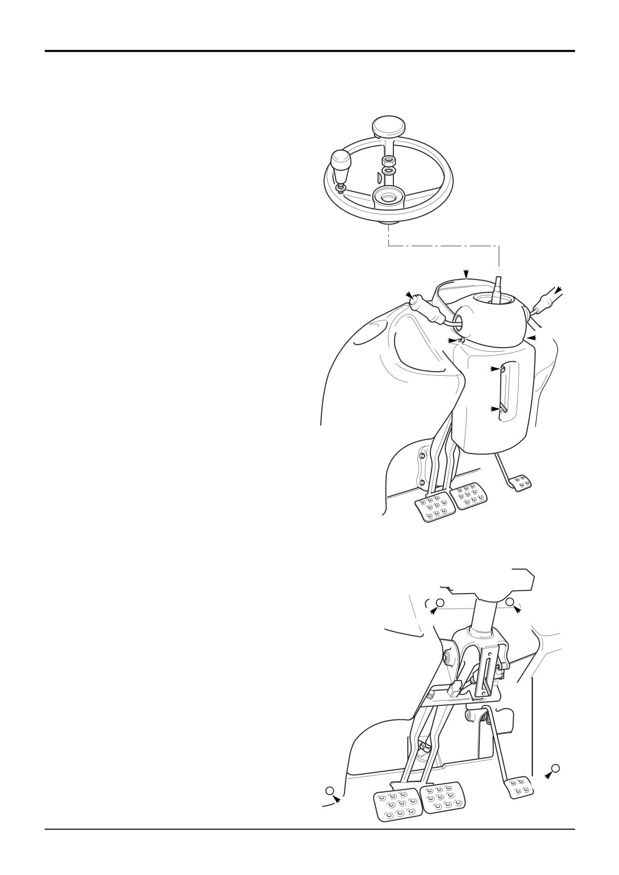
Front/Steering Console
Removal
1
Park the machine on firm level ground, apply the
parking brake. Lower the loader arms and excavator to
the ground, switch OFF the engine and remove the
starter key.
2
Disconnect the battery.
3
Working in the cab, remove the steering wheel as
shown.
C
4
Remove the fixings A (4 off) at positions shown and take
B
off the steering column pedestal cover.
B
5
Remove the column switches B.
6
Remove the instrument panel C.
A
A
7
Remove the fixings D (4 off) securing the front console
panel at positions shown and then carefully lift up the
A
front console clear of the steering column assembly.
Replacement
A
Replacement is the reverse of the removal sequence.
Take care when removing/replacing the console panel to
ensure that harnesses do not become snagged and that no
other connections have been disturbed.
After re-fitting, operate the front/steering console controls
and check they all function correctly.
D
D
D
D
A396920
9803/3280
Issue 1
Section C
Electrics
Section C
i
i
Contents
Page No.
Service Tools
1-1
Technical Data
System Type
2-1
Battery
2-1
Alternator
2-1
Fuses & Relays
2-2
Fuse Link Box
2-3
Relays
2-3
Basic System Operation
Circuit Schematics
Basic Machine - 3CX, 4CX, 214, 215, 217 (Not 214e)
4-1
Synchro Shuttle and Powershift
4-5
Options
- Steer Mode (4x4x4)
4-7
- 2 Wheel Steer/Brake Mode
4-7
*
*
- 2 Wheel Steer/Brake Mode (Germany)
4-7
- All Wheel Steer/Brake Mode
4-9
- Auxiliary and Hydraclamp Hydraulics
4-9
- Speedometer
4-9
- Hand Held Tools
4 - 11
- Dedicated Quickhitch
4 - 11
- Pole Planter
4 - 11
- Smooth Ride System (SRS)
4 - 11
- Return to Dig (Shovel Reset)
4 - 11
- Hydraulic Speed Control (HSC)
4 - 11
*
6 Speed Powershift (Shiftmaster)
4 - 13
*
214e Machines
4 - 15
Service Procedures
Electrical Testing Methods
Using a Multimeter
19 - 1
- Measuring DC Voltage
19 - 3
- Measuring Resistance
19 - 3
- Measuring Continuity
19 - 3
- Testing a Diode
19 - 5
Battery
Maintenance
20 - 1
Safety
20 - 1
Testing
20 - 2
Specific Gravity Testing
20 - 2
Alternator
Charging Test
21 - 1
Starter Motor
Starting Circuit Test
22 - 1
Wiring Harness
Repair Procedure
23 - 1
9803/3280
Issue 3*
Section C
Electrics
Section C
ii
ii
Contents
Page No.
Alternator
Removal and Replacement
30 - 1
Starter Motor
Removal and Replacement
40 - 2
Inspection
40 - 2
Dismantling and Assembly
40 - 2
Earth Points
145 - 1
Harness Data
Drawings
150 - 1
*
Harness Interconnection
150 - 1
9803/3280
Issue 3*
Section C
Electrics
Section C
1 - 1
Service Tools
1 - 1
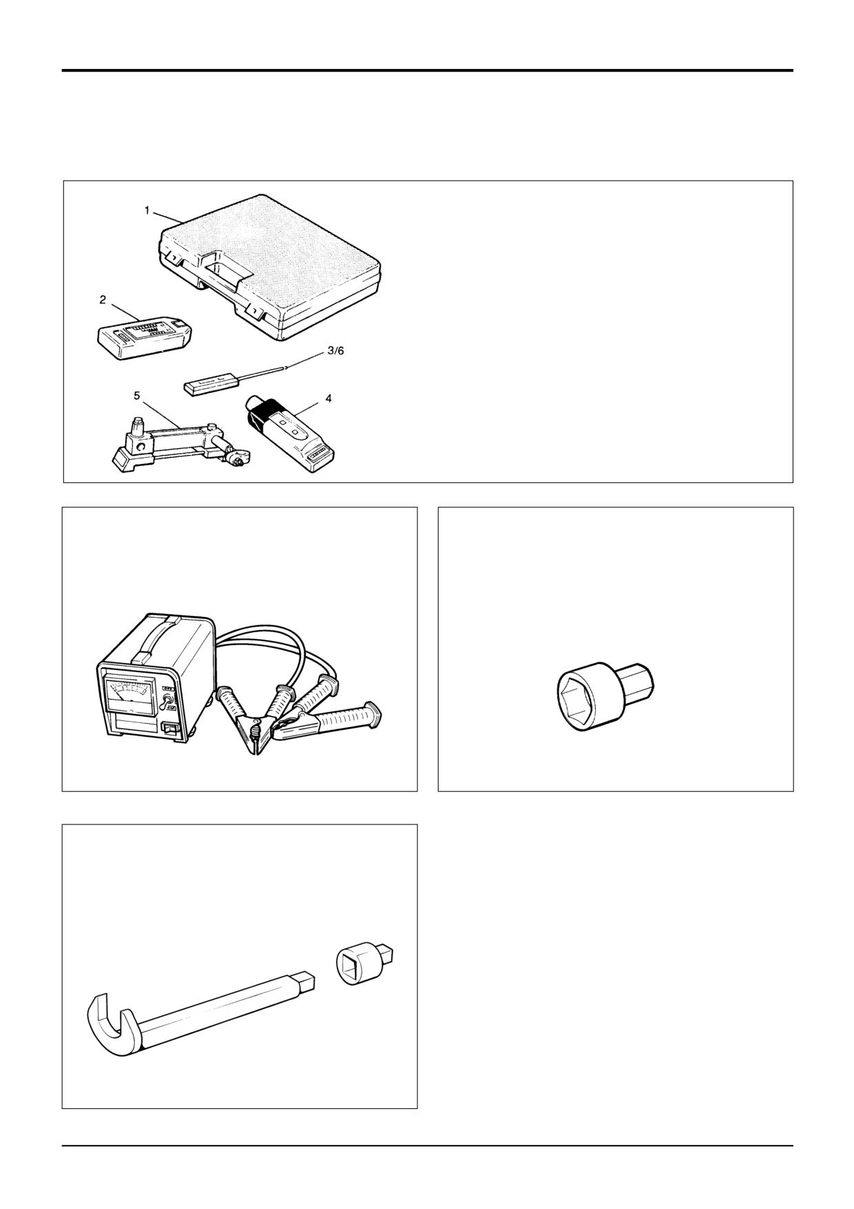
AVO Test Kit
1
892/00283
Tool Kit Case
2
892/00298
Fluke Meter 85
3
892/00286
Surface Temperature Probe
4
892/00284
Venture Microtach Digital
Tachometer
5
892/00282
100 amp Shunt - open type
6
892/00285
Hydraulic Temperature Probe
S188231
993/85700
Battery Tester
892/00882
Socket for Alternator Pulley Nut
S239510
S216770
825/00410
15 mm Crowfoot Wrench
825/99833
Adapter
S216200
9803/3280
Issue 1
Section C
Electrics
Section C
2-1
Technical Data
2-1
General Electrical Data
System Type
12 Volt, negative earth
Battery (Heavy Duty)
- Cold crank amps for 1 minute to
1.4 volts per cell at -18 deg C (0 deg F)
550
- Reserve capacity (minutes) for 25 amp load
220
Battery (Temperate)
- Cold crank amps for 1 minute to
1.4 volts per cell at -18 deg C (0 deg F)
410
- Reserve capacity (minutes) for 25 amp load
170
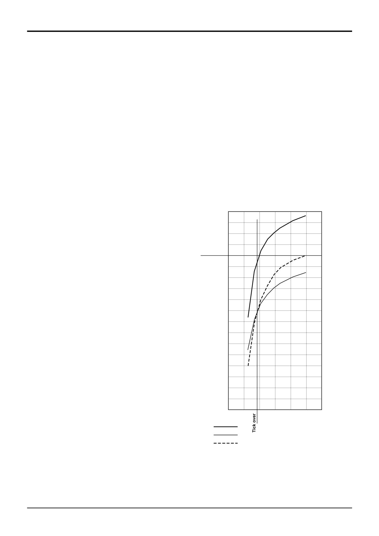
Alternator
2WS
65 Amp nominal output
4WS
72 Amp nominal output
4WS (air conditioning or ServoPlus builds)
85 Amp nominal output
90
85
80
75
Max load
70
65
60
55
50
Output
45
amps
40
35
30
25
20
15
10
5
0
0
500
1000
1500
2000
2500
3000
Engine speed
85A
rpm
65A
72A
A323770
9803/3280
Issue 1
Section C
Electrics
Section C
2-2
Technical Data
2-2
Fuses and Relays
Fuses
10
10
10
9
9
9
8
8
8
7
7
7
! CAUTION
6
6
6
5
5
5
4
4
4
Always replace fuses with ones of correct ampere rating
3
3
3
2
2
2
to avoid electrical system damage.
1
1
1
8-3-3-5
C
B
A
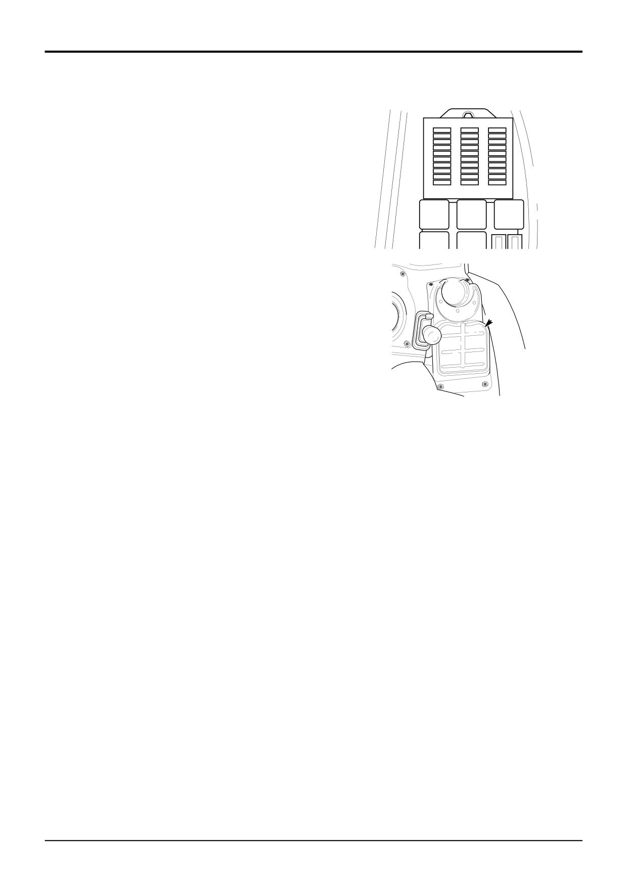
The relays and fuses are located in the side console
underneath cover A.
396500
If a fuse melts, find out why and rectify the fault before fitting
a new one. The fuses are identified using column letters (A,
B and C) and row numbers (1 to 10). Note that all the fuses
are shown (including optional equipment fuses). Your
machine may not be equipped with all the fuses shown.
A
396490
Machines up to serial no. 933756
*
Machines from serial no. 933757
COLUMN ‘A’
Fuse Rating
COLUMN ‘A’
Fuse Rating
1
Hydraulic auxiliary
10 Amp
1
Hydraulic auxiliary
10 Amp
2
Fuel pump solenoid (engine stop)
5 amp
2
Fuel pump solenoid (engine stop)
5 amp
3
Direction indicators
7.5 amp
3
Direction indicators
7.5 amp
4
Steer mode proximity switch
7.5 Amp
4
Steer mode proximity switch
7.5 Amp
5
Gearbox control, Transmission
10 Amp
5
Transmission
10 Amp
6
Spare
6
Gear select / Forward Reverse
3 Amp
7
Brake lights
5 Amp
7
Transmission
10 Amp
8
4 wheel drive (automatic brakes)
3 Amp
8
Brake lights
7.5 Amp
9
Left hand side lights
5 Amp
9
Left hand side lights
5 Amp
10
Right hand side lights
5 Amp
10
Right hand side lights
5 Amp
COLUMN ‘B’
COLUMN ‘B’
1
Instruments, Buzzer
5 Amp
1
Instruments, Buzzer
5 Amp
2
Front horn, Front washer/wiper
15 Amp
2
Front horn, Front washer/wiper
15 Amp
3
Rear horn
7.5 Amp
3
Rear horn
7.5 Amp
4
Heated seat, Cigar lighter, Face level fan
15 Amp
4
Heated seat, Cigar lighter, Face level fan
15 Amp
5
Rear wiper/wash
10 Amp
5
Rear wiper/wash
10 Amp
6
Brake switch
10 Amp
6
Brake switch
10 Amp
7
Return to dig enable
5 Amp
7
Return to dig enable
5 Amp
8
Rear working lights
25 Amp
8
Rear working lights
25 Amp
9
Headlights
20 Amp
9
Headlights
20 Amp
10
Front working lights
25 Amp
10
Front working lights
25 Amp
COLUMN ‘C’
COLUMN ‘C’
1
Lights
7.5 Amp
1
Lights
7.5 Amp
2
Hazard light
15 Amp
2
Hazard light
15 Amp
3
Beacon, Interior light
10 Amp
3
Beacon, Interior light
10 Amp
4
Radio
5 Amp
4
Radio
5 Amp
5
Thermostart
20 Amp
5
Thermostart
20 Amp
6
Heater
30 Amp
6
Heater
30 Amp
7
Ignition relay coils
3 Amp
7
Ignition relay coils
3 Amp
8
Main beam
15 Amp
8
Main beam
15 Amp
9
Fog light
3 Amp
9
Fog light
3 Amp
10
Dip beam
15 Amp
10
Dip beam
15 Amp
9803/3280
Issue 3*