Dubai Building Code (2021) - page 26
 

  Index      Manuals     Dubai Building Code (2021)


Search            copyright infringement  


Content      ..     24      25      26      27     ..


Dubai Building Code (2021) - page 26


Dubai Building Code

Part K: Villas

K 69

Regulations (2010), Approved Document Part K, 2013 Edition. Contains public sector information licensed 

under the Open Government Licence v3.0)

In accordance with Section 5, Ch. 1 of UAE FLSC 

[Ref. K.1]

, safety glazing for use in 

critical locations shall conform to the minimum classifications in either Table K.16 or 

Table K.17.

Critical location

Height

Classification in test standard 

BS EN 12600

Low-level areas 

All height

Class 1

Doors
Doors side panel 

Below 900 mm from FFL

Class 2

Above 900 mm from FFL

Class 3

Table K.16  Minimum classification for safety glazing requirements

Table K.17  Minimum classification for safety glazing requirements

Area of glazing in critical 

location (m

2

)

Classification in test standard

ANSI Z97.1

CPSC 16 CR 1201 

[Ref. K.13]

≤0.9

A

I

>0.9

B

I

K.7.6.2 

Containment

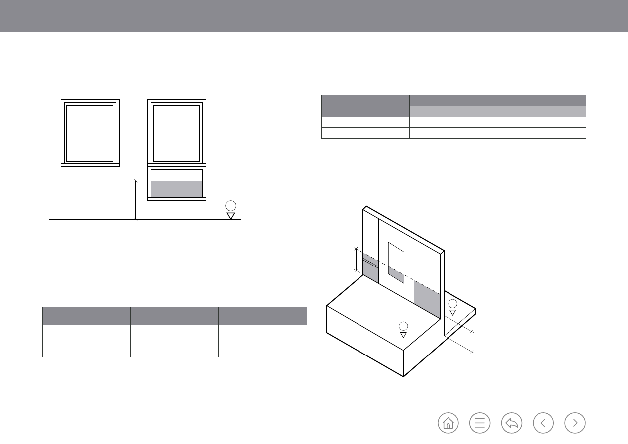
Glazing at areas lower than 800 mm from FFL and protecting a change in level 

greater than 760mm shall provide containment, as shown in Figure K.54.

Figure K.54 

Examples of glazed areas that need to provide containment

Key

01: Internal FFL 

02: External FFL

800

01

>760

01

02

800

Key

01:Floor level

Dubai Building Code

Part K: Villas

K 70

If a glazing panel covers areas above and below 800mm from FFL, the entire glazing 

panel shall provide containment.

K.7.6.3 

Overhead glazing

Overhead glazing shall be laminated. It shall include a post-breakage containment 

system, such that if the glass breaks, the glass is held in place until it can be replaced.
The safety and fragility of overhead glazing shall be determined in accordance with 

CWCT TN 66 

[Ref. K.14]

Overhead glazing shall be tested in accordance with CWCT TN 67 

[Ref. K.15]

K.7.7 

Fire safety 

K.7.7.1 

General

The fire safety of building envelopes (façade and roofs) shall conform to Ch. 1 of UAE 

FLSC 

[Ref. K.1]

 and the specific requirements of this section. 

The requirements for guardrails and balustrades as described in Section 2.17,  

Ch. 1 of UAE FLSC 

[Ref. K.1]

 are superseded by K.5.2.5.2.

The requirements for safety glazing in Sections 5.4.2 to 5.4.4, Ch. 1 of UAE FLSC 

[Ref. K.1] are superseded by K.7.6.

K.7.7.2 

Fire testing of non-fire-rated, non-load-bearing façades and aesthetic 

features/mashrabiya

The requirements of Section 4.2.1, Ch. 1 of UAE FLSC 

[Ref. K.1]

 shall be met, with 

the following amendments.
a) 

The exceptions listed in Section 4.2.1, Ch. 1 of UAE FLSC 

[Ref. K.1]

 are expanded 

to include concrete, terracotta, glass, ceramics and mineral wool.

b) 

In addition to the materials listed in Section 4.2.1, Ch. 1 of UAE FLSC 

[Ref. K.1]

solid metal panels conforming to K.7.7.3 may be used.

The requirements in Section 4.5, Ch. 1 of UAE FLSC 

[Ref. K.1]

 shall be met, with the 

following amendments.
1) 

Steel flashing is not required around window openings.

2) 

Flashing shall match the flashing included in the NFPA 285 fire test(s) forming 

the basis of the fire safety design(s) of the façade.  

K.7.7.3 

Solid metal panels

Solid metal panels, including any coatings, shall conform to Sections 4 to 7, Ch. 1 of 

UAE FLSC 

[Ref. K.1]

 and shall achieve the fire safety classifications and fire safety 

performance criteria of Table K.18 where applicable.

Occupancy and type of building Fire testing required for solid 

metal panel

Fire testing required for façade 

assembly

Low-rise building  (e.g. villa, 

townhouse)     

Panel shall be tested in the 

thickness intended to be used, 

including any coatings to  

BS EN 13501-1 with pass 

criteria B-s1-d0

BS 8414-1 or BS 8414-2 with 

pass criteria in accordance with 

BR 135 

[Ref. K.16]

.

or

NFPA 285

with pass criteria “pass”
or

FM 4881 

with pass criteria “pass”
or 
ISO 13785-2 
with pass criteria “pass”

Table K.18  Fire test requirements for solid metal panels on non-fire resistance rated and non-load-bearing 

exterior building envelope and aesthetic features/mashrabiya.

Dubai Building Code

Part K: Villas

K 71

K.7.7.4 

Roof assemblies

Roofing systems shall conform to the performance requirements of Section 6, Ch. 1 

of UAE FLSC 

[Ref. K.1]

.

K.7.8 

Solar panels

Photovoltaic (PV) cells or panels installed on roofs or façades shall conform to 

Section 2.2, Ch. 14 of UAE FLSC 

[Ref. K.1]

. If PV panels are attached to or integrated 

with the façade then they shall also be tested in accordance with Section 4,  

Ch.1 of UAE FLSC 

[Ref. K.1]

.

K.7.9 

Maintenance

A method of safely maintaining the building envelope shall be provided. 
Permanent maintenance equipment attached to either roof or façades shall be 

treated as permanent fixture loading (see K.7.1.1.4).
Hard or sharp components of the maintenance equipment shall be covered with soft 

protection prevent the building envelope from being impacted. 
The energy impact that the maintenance equipment or operator might exert on 

the building envelope shall be calculated. The building envelope shall be capable of 

withstanding applied or transferred impacts that might occur during maintenance 

without sustaining damage that is not repairable and without deterioration of its 

performance. 

Dubai Building Code

Part K: Villas

K 72

K.8 

Structure

K.8.1 

Structural system requirements

K.8.1.1 

General conditions

The structural design of buildings shall be undertaken 

by the Engineer. The Engineer shall only use 

appropriate structural analysis and design software, 

approved by the Authority.
Villas/townhouses and all their components, as well as 

materials, shall satisfy the minimum safety standards 

defined herein and the referenced documents.

The design shall facilitate safe fabrication, transport, 

handling and erection with due regard to site-specific 

conditions. As far as is reasonably practicable, it shall 

also take account of the needs of maintenance, final 

demolition, recycling and reuse of materials.

Typical design issues are presented in Figure K.55 for 

inclusion in the design stages.

K.8.1.2 

Design life

The recommended minimum design life for villas/

townhouses is 50 years. The Engineer shall discuss and 

agree the design life of the structure with the Owner 

and the Authority before the design commences. The 

Engineer shall clearly specify the adopted design life in 

the design documentation. 

OPTIMIZED STRUCTURAL 

DESIGN

MATERIAL

SPECIFICATION

BUILDABILITY

AESTHETICS

SUSTAINABILITY

MAINTENANCE

MOVEMENT

STRUCTURAL 

PERFORMANCE

SUBSOIL PERFORMANCE

COST

SAFETY/RISK

Substructure

Superstructure

Site

Access

Ground conditions

Weather

Recycling

Re-using

Pollution

Energy

Construction

Use

Re-use

Decommissioning

Appearance

Sense of place

Bearing

Settlement

Soil retention

Liquefaction

Groundwater

Design

Construction

Maintenance

Decommissioning

Strength

Sti

ffne

ss

Durability

Stability

Robustness

Dead load

Live load

Wind

Seismic

Soil pressure

Blast

Wave

Thermal

Alternative sources

Embedded energy

Energy consumption  

during building life

W

hole

 life

 costi

ng

Fire

Figure K.55 

Typical issues in relation to structural design requirements

Dubai Building Code

Part K: Villas

K 73

K.8.1.3 

Design acceptance criteria

The design shall honour all design acceptance criteria 

defined by the design basis codes and standards 


(see K.3.5).
Ordinarily, these acceptance criteria are defined as limit 

states. As applicable, designs shall include: 
a)  strength limit states including general yielding, 

rupture, buckling and transformation into a 

mechanism;

b)  serviceability limit states including member and 

global deflections, vibration and occupancy comfort;

c)  stability against overturning and sway;
d)  fracture due to fatigue and brittle fracture;
e)  corrosion and durability;
f) 

fire; and

g)  accidental loads (blast, impact, etc.).

K.8.1.4 

Structural system and robustness

Measures shall be taken to ensure that the building is 

stable under the design basis load conditions. Where 

necessary, these measures shall also allow for the 

maximum credible loads for which the collapse limit 

state might be chosen as being applicable.
Any features of the structure that have a critical 

influence on its overall stability shall be identified and 

included in the design, including all members that 

provide restraint to critical members in compression.  

A structure shall be designed to behave as one three-

dimensional entity. The layout of its constituent parts, 

such as foundations, primary frame, steelwork, joints 

and other structural components should constitute 

a robust and stable system under normal loading to 

ensure that, in the event of misuse or accident, damage 

will not be disproportionate to the cause. 
Measures shall be taken to ensure that the building 

is robust and resistant to disproportionate collapse 

under the specified load conditions. The Engineer 

shall include implicit considerations of resistance to 

progressive collapse during the design process through 

the provisions stipulated under Appendix C of ASCE/

SEI 7-16 (indirect design approach). 

K.8.1.5 

Durability

All elements shall be designed with appropriate 

detailing and material specifications to achieve the 

specified design life, considering the environment of 

the project and the whole lifecycle of the building.   

The following specific requirements shall be met.

a) 

For concrete structures, the Engineer shall 

implement the recommendations of BS EN 206 

and BS 8500-1 in the design and specifications of 

concrete structures. The criteria listed under 

F.11


shall also be followed.

b) 

For steelwork structures, the Engineer shall provide 

the steelwork material specifications, stating the 

steel grades and protective paint systems which are 

durable and compatible with the climate of Dubai. 

The paint protective coatings for steelwork shall 

be specified in accordance with BS EN 12944 as a 

minimum, with additional requirements to address 

the susceptibility of the protective coatings to ultra 

violet degradation. 

K.8.2 

Fire resistance

Villas shall be classified group A or group B in 

accordance with Table 1.1, Ch. 1 of  

UAE FLSC 

[Ref. K.1]

.

Construction type and fire resistance of the structure 

shall be defined based on the classification of the villa, 

the height and general arrangement of the largest 

storey of the villa and whether it is sprinkler protected 

or not in accordance with Table 1.7, Ch. 1 of  

UAE FLSC 

[Ref. K.1]

Villas/townhouses do not require fire-rated or listed 

roof assemblies (see Section 6.3.7, Ch. 1 of  

UAE FLSC 

[Ref. K.1]

). 

The structure supporting 2 h fire-rated walls between 

townhouses (see K.5.11) shall also achieve 2 h fire 

resistance. 

Dubai Building Code

Part K: Villas

K 74

Material 

Code of reference

Remarks

Reinforced concrete

ACI 318-19

Post-tensioned concrete ACI 318-19

TR43 

[Ref. K.20]

 can be adopted as 

further reference

Pre-cast concrete

ACI 318-19 and Precast/

prestressed Concrete Institute (PCI) 

design handbook 

[Ref. K.21]

Steel 

AISC 360 and AISC 341-16

Masonry

TMS 402/602:2016 or  

BS EN 1996-1, 2 and 3

Load-bearing masonry shall conform 

to TMS 402/602:2016.

Aluminium

IBC Ch. 20 

[Ref. K.2]

IBC refers to AA ASM 35, Aluminium 

Sheet Metal Work in Building 

Construction, and AA ADM 1, 

Aluminium Design Manual.

Wood

IBC Ch. 23 

[Ref. K.2]

Gypsum board

IBC Ch. 25 

[Ref. K.2]

Plastic

IBC Ch. 26 

[Ref. K.2]

Table K.19 

Codes of reference for the material requirements

K.8.3 

Materials

The structural design shall meet the material requirements specified in the codes and 

standards listed in Table K.19. 

Other materials, such as aluminium, timber, gypsum board, glass and plastic, shall be 

used only where also permitted by Ch. 1 of UAE FLSC 

[Ref. K.1]

The specification of all constituent materials of the structural system shall be 

compatible with the specified codes and clearly detailed in the design documentation.

Structural designs can be prepared by referring to building codes and standards 

other than those mentioned in Table K.19, subject to obtaining the approval of the 

Authority. 

K.8.4 

Loads

K.8.4.1 

General

Loads shall be defined in accordance with ASCE/SEI 7-16 and this section. 

K.8.4.2 

Load combinations

Loads shall be factored and combined in accordance with Ch. 2 of ASCE/SEI 7-16.

The results from compatible linear analyses of load cases acting individually may be 

combined and summed algebraically.

K.8.4.3 

Dead loads 

Dead loads shall be calculated using the densities and volumes of the materials 

making up the construction.

Default densities of common materials are scheduled in Table K.20. 

NOTE: More refined densities and the densities of other materials can be sourced 

from the referenced codes and standards, material data sheets, or obtained via 

testing. The Engineer is responsible for ensuring the densities assumed in design 

align with those of the specified construction materials.

Description

Load (kN/m

3

)

Concrete (normal weight, including allowance for reinforcement)

25

Concrete (lightweight, including allowance for reinforcement)

18

Concrete blockwork (normal weight)

20

Concrete blockwork (autoclave aerated block)

7

Steel

78

Screed and blinding

20

Float glass

25

Table K.20 

Default material densities

Where appropriate, dead loads shall make provision for additional weight 

concentrated at structural connections.

Dubai Building Code

Part K: Villas

K 75

K.8.4.4 

Superimposed dead loads

The Engineer is responsible for determining the superimposed dead loads for 

components not included as either live or dead loads (including the anticipated 

internal partitions, floor and ceiling finishes, facades and external cladding). Loads 

shall be defined as concentrated point loads, uniform loads on plan, and/or uniform 

loads on elevation, as appropriate. 

The following minimum load allowances (defined as average uniform loads on plan) 

shall be adopted for the purpose of evaluating the maximum load effect:
a)  internal drywall partitions:  


0.75 kN/m

2

;

b) 

suspended services with ceiling finishes:  

0.50 kN/m

2

;

c) 

suspended services without ceiling finishes: 

0.30 kN/m

2

.

The Engineer shall provide detailed calculations supporting the superimposed dead 

load assumptions. If supporting calculations are not provided, the vertical load listed 

in Table K.21 shall be included for the partition assumptions. 

Type of wall

Superimposed dead load applied vertically, including finishes (kN/m

2

)

Lightweight block wall

4.5 

Normal weight block wall

5.5 

Drywall 

4.0 

Table K.21 

Minimum superimposed dead load

Loading plan drawings showing the load provision should be submitted for approval. 

The design assumptions shall be validated against the systems installed. Any late 

amendments and/or retrospective changes shall not be made without new approval.

K.8.4.5 

Live loads

Minimum uniform live loads shall be not less than those listed in Ch. 4  

of ASCE/SEI 7-16. The following requirements shall also be followed.
a) 

Concentrated live loads shall be evaluated for objects creating significant point 

loads, including machinery, vehicles and storage racks. 

b) 

The minimum live load for garage and car parking is 3.5 KN/m

2

 which should be 

validated based on the type of vehicles accessing the facility. 

c) 

The live load for drained areas of floor surrounding a swimming pool is 2 kN/m

2

Pool tanks and other areas susceptible to flooding shall be designed for a load not 

less than the maximum retained head of water.

d)  The Engineer shall design the supporting structure to withstand the loading 

imposed by the mechanical, electrical and public health (MEP) equipment in the 

designated areas and along the proposed equipment access route.

K.8.4.6 

Soil loads and hydrostatic pressure

Minimum soil and hydrostatic pressures shall be not less than those listed in  

Table K.22. Lower values shall not be used without project specific justification. 

Description

Minimum load (kN/m

3

)

Soil for planters (saturated)

19

Compacted soil for trafficable areas

22

Water

10

Brackish water

10.3

Table K.22 

Material densities

Dubai Building Code

Part K: Villas

K 76

In addition to the geotechnical requirements specified under K.8.6, the Engineer shall 

include the following aspects in the design of permanent structures:
a)  All foundation elements and retaining walls shall be designed by the 

recommendations given in the geotechnical interpretive report (GIR). 

b) 

The design water table shall be established in the GIR considering the fluctuation 

of the water table level during the design life of the structure. In particular, the 

effect of dewatering in the neighbouring areas, the seasonal variation of the water 

table, future developments (such as canal, water bodies, landscaping and similar) 

and potential impact of climate change shall be included in the definition of the 

design groundwater level. The design groundwater level and its fluctuations shall 

be stated by the Engineer in the design drawings and agreed with the Authorities. 

c)  In any case, the minimum water table level shall be assumed as follows:

1) 

in proximity to bodies of water: ±0.00 m Dubai Municipality Datum (DMD) 

plus 1.0 m for seasonal and tidal variations and

2)  away from bodies of water: actual water table level with dewatering taken into 

account, as defined in the GIR, plus 1.0 m for seasonal and tidal variations.

d) 

For structures below the water table, hydrostatic uplift and lateral pressures shall 

be checked in accordance with Section 10 of BS EN 1997-1:2004+A1:2013 and 

the associated UK NA. Any dewatering system, whether used for construction or 

throughout the design life, is temporary unless the system can be demonstrated 

to be reliable throughout the design life. 

e)  Where construction of the project is staged, or in case of construction on an 

adjacent plot, any possibility of unbalanced lateral soil load shall be included. 

f)  Any retaining wall assumed to be subjected to lateral pressure during 

construction shall be designed according to possible surcharge and hydrostatic 

loading. The lateral soil pressure arising from compacted soil placement shall be 

included where this exceeds the at rest or passive pressure (as relevant).

g)  Bracing conditions of the retaining structure and construction sequence shall be 

carefully captured in the analysis and design. 

h)  Uplift due to heave shall also be included for both permanent and temporary 

conditions whenever applicable. 

K.8.4.7 

Construction load

Minimum design load requirements during construction of buildings shall be defined 

in accordance with ASCE 37.
Construction-stage loads, including locked-in stresses arising from the construction 

sequence and affecting the overall behaviour of the structure, shall be included by the 

Engineer.
The Engineer shall clearly state the construction load assumptions on the detailed 

design drawings and verify that the structural system can withstand these loads 

during all stages of construction. 
Any departure from the Engineer’s assumptions that are invoked by the Contractor’s 

construction sequence shall be assessed.

K.8.4.8 

Accidental impact load

Structural elements shall be designed to resist accidental impact loading conditions 

specified under Section 4.6 of ASCE/SEI 7-16. A secondary protection system should 

be provided to all primary structural members to avoid accidental impact load.

K.8.4.9 

Self-straining forces

Structures shall be designed to resist any self-straining forces arising from the 

contraction or expansion of structural elements. 
Such volume changes can result from shrinkage, creep and/or moisture change in 

component materials, including the soil. It might occur at any stage in the structure’s 

lifecycle. 
The use of details to alleviate self-straining forces may be used when practical and 

not in violation of any assumed load paths. Such details, where permanent, shall be 

durable and/or have provision for maintenance. 

Dubai Building Code

Part K: Villas

K 77

K.8.4.10  Thermally induced forces

Thermally induced forces shall be derived considering the structural restraints, and 

the changes in temperature of structural members arising across the construction/

operational phases, seasonal and daily variations.

For effects on covered concrete structural members, mean monthly temperatures 

should be used to establish an appropriate range. A default thermal range of ±20 °C 

may be used for exposed concrete elements and ±15 °C for non-exposed concrete 

elements. 

For steel structural members and structural members exposed to solar radiation, 

a range equivalent to the maximum temperature swing is appropriate. A default 

thermal range of ±25 °C may be used for protected steel elements. For exposed 

steelwork, this can arise from hourly maxima and minima. The Engineer shall assess 

the thermal range and assess the thermally induced forces on a case by case basis 

considering the construction stages, exposure and when the steel structure is locked 

in the final configuration. 

NOTE: Relative humidity values and mean monthly temperature for specific sites are 

available from the National Centre for Meteorology and Seismology website  

[Ref. K.17]

.

K.8.4.11  Design for wind loading effects

K.8.4.11.1  General

The Engineer shall calculate the effects of wind loading, taking into account strength 

for life safety, and serviceability for building movements affecting cladding or building 

occupant comfort. 
Calculations for wind design shall be based on ASCE/SEI 7-16 and additional rules 

for application in Dubai from this section.

K.8.4.11.2  Wind pressures

This subclause provides the basis for calculation of wind pressures to be used with 

ASCE/SEI 7-16. 

The wind speeds of Table K.23 replace the use of the wind maps of Section 26.5 


or ASCE/SEI 7-16. Wind reference speed for 50 MRI shall be used only for strength 

design in accordance with Clause 5.3.5 of ACI 318 19.

Application – risk category

Reference wind speed, V = Vref 

(m/s)

ASCE/SEI 7-16 MRI (years)

Strength

38

50

Strength – category II*

47

700

Serviceability – deflections

30

10

* Risk category is described in Section 1.5 of ASCE/SEI 7-16. For villas/townhouses in Dubai, use 

category II.

Table K.23 

Reference wind pressures and speeds per risk category and mean recurrence interval (MRI) 

(extracted from 

[Ref. K.18]

)

In all cases, the design wind pressure shall be not less than 1 kN/m

2

.

K.8.4.12  Design for earthquake effects

Every villa/townhouse, and portion thereof, including non-structural components 

that are permanently attached to structures and their supports, shall be designed 

and constructed to resist the effects of earthquake motions in accordance with 

ASCE/SEI 7-16 (Section 11.1.2) and 

F7.13

.

Dubai Building Code

Part K: Villas

K 78

K.8.5 

Structural performance and serviceability requirements

K.8.5.1 

Design basis

The basis of design for villas/townhouses shall include these aspects as a minimum:
a)  strength; 
b) 

deflection control in concrete and steel structures;

c)  crack control in concrete structures;
d)  building movement and motions due to wind;
e)  building movement due to seismic;
f)  movement joint and building separation;
g)  vibration;
h)  lateral acceleration;
i)  fatigue; and
j)  additional requirements for transfer elements.

K.8.5.2 

Strength

Villas/townhouses and parts thereof, shall be designed and constructed to support 

safely the factored loads in load combinations defined in this section without 

exceeding the appropriate strength limits states for the material of construction. 

K.8.5.3 

Deflection control

Deflection limits shall be adopted that enable functional requirements to be 

maintained. Limits may be governed by the requirements of internal and/or external 

furniture, finishes, fixtures and fittings.
Vertical and horizontal deflections shall be within the limits specified in the 

referenced design standards, as applicable, and the project specific requirements.
When checking for deflections the most adverse realistic combination and 

arrangement of serviceability loads shall be included. 

The Engineer shall verify that the adopted deflection limits will enable the functional 

performance of the building to be maintained. In particular, the following apply.
a) 

Deflection limits for steel structures shall conform to the requirements stipulated 

in AISC 360 and AISC design guide 3 

[Ref. K.24]

b) 

Deflection limits for concrete slabs and beams shall be in accordance with 

24.2.2 of ACI 318-19. The value of the incremental deflection shall not exceed 

20 mm after the installation of partition and finishes and shall be calculated in 

accordance with ACI 435R-95 and ACI 318-19. When evaluating the deflection 

of concrete structures, the detrimental effects of cracking shall be included by 

modifying the stiffness (EI) for areas which have exceeded the allowable tensile 

stresses. The modified EI shall be chosen based on the extent of cracking under 

the design load. Default stiffness modifiers given in ACI 318-19 may be followed 

for regular structures subject to approximately uniform loads.

c)  Design for strength and serviceability requirements of post-tensioned concrete 

members shall conform to ACI 318-19. Structural calculations shall verify that 

both short and long-term deflections, camber, vibration frequency and amplitude 

are within permissible limits.

K.8.5.4 

Crack control in concrete structure

The Engineer shall perform crack width calculation checks for reinforced concrete 

structures in accordance with ACI 224R.

In the absence of more specific requirements, the following maximum crack width 

limits shall be adopted:
a) 

For section of the structure in contact with groundwater, the crack width limits 

(w

k

) are defined as a function of the ratio of the hydrostatic pressure, h

D

 to the 

wall thickness of the containing structure, h

w

.

1) 

For h

D

/h

w

 <5, w

k

 = 0.2 mm.

2) 

For h

D

/h

w

 >35, w

k

 = 0.05 mm. 

Dubai Building Code

Part K: Villas

K 79

b) 

For intermediate values of h

D

/h

w

, linear interpolation between 0.2 mm and 0.05 

mm may be used.

c)  Section of the structure not in contact with water: w

k

 = 0.3 mm.

d)  Structural elements (such as piles) under permanent tension loads: w

k

 = 0.1 mm.

The above listed limits may be adopted providing that they do not contradict the 

requirements of ACI 224R and a proprietary waterproofing system is provided for 

structural elements in contact with water in accordance with BS 8102. 

It is also recommended that basements and liquid retaining structures are classified 

in relation to the degree of protection against leakage. An appropriate limit to 

cracking depending on the classification should be selected by the Engineer and 

Owner’s representative, paying due regard to the required function of the structure, 

the intrinsic durability requirements, soil and water properties. Where structural 

walls, columns and piles provide significant restraint to shrinkage and temperature 

movements, it is recommended that the reinforcement provisions are verified against 

the requirements stated under either ACI 89-S15 (as in R24.4.2 of ACI 318-19) or 

CIRIA C766 

[Ref. K.22]

K.8.5.5 

Drift and deformation

K.8.5.5.1  General

The Engineer shall assess the drift and deformation of the building considering the 

whole life of the structure, including the construction stages. 

K.8.5.5.2  Drift and deformation due to wind

Building overall displacements shall be calculated using 10-year return (MRI) wind 

pressures and total building height (H). The overall displacement of the building due 

to wind action shall be limited to H/500 using the serviceability parameters listed in 

Table K.23. 

The displacement limits may be varied provided that provision for any larger than 

normal movements is clearly specified on drawings and implemented.

The purpose of this calculation is to control displacements of the building which 

can cause overstress or fatigue damage or loss of effectiveness to cladding, internal 

partitions or other non-structural components of buildings.

K.8.5.5.3  Drift and deformation due to seismic

Movements of buildings due to earthquake effects shall conform to the requirements 

stipulated under Section 12.12 of ASCE/SEI 7-16. 

K.8.5.6 

Movement joints and building separation

Movement joints shall be provided, where necessary, to address the requirements  

of expansion and/or deflection under load for above-ground structures. 


The minimum separation between a structure and any surrounding obstructions shall 

be not less than the total maximum displacement, as specified in Section 12.12 of 

ASCE/SEI 7-16.

Movement joints are a common source of water infiltration. Structures below ground 

level should be designed without movement joints to mitigate the risk of water 

ingress. Design for construction without permanent joints below ground level can  

be achieved by following the recommendations provided in CIRIA C766 

[Ref. K.22]

K.8.5.7 

Vibration

Vibration and oscillation of building structures should be limited to avoid discomfort 

to the users, damage to contents or damage to the structure, as detailed below. 
a) 

Steelwork. The natural frequency of steelwork floor systems for normal 

occupancy shall be evaluated in accordance with AISC Design guide 11 

[Ref. K.25]


or SCI P354 

[Ref. K.26]

.

Dubai Building Code

Part K: Villas

K 80

b) 

Reinforced concrete. Cast-in-place floor systems designed in accordance with the 

minimum thickness and deflection requirements of ACI 318-19 have generally 

been found to provide vibration performance suitable for human comfort under 

typical service conditions. However, there might be situations where serviceability 

conditions are not satisfied, for example:

1) 

long spans and open floor plans;

2)  facilities subject to rhythmic loadings or vibrating mechanical equipment.

NOTE: Further guidance is given in the ATC Design Guide 1 

[Ref. K.23]

c) 

Post-tensioned slab. The performance of post-tensioned concrete floors may 

follow the recommendation of TR43 

[Ref. K.20]

 Table 1 and Appendix G. 

d)  Precast concrete. Structures shall be checked for vibration as detailed in  

Section 9.7 of PCI design handbook 

[Ref. K.21]

K.8.5.8 

Fatigue

Structural members that support significant vibrating machinery, vehicles or plant 

should be checked for fatigue resistance. Where fatigue is critical, all design details 

shall be fully defined, including clear specification of the workmanship and quality 

assurance tests. The design shall be checked in accordance with the following codes:
a)  Appendix 3 of AISC 360-16 for steel; and
b)  ACI 318-19, ACI 215R and ACI 408.2R for concrete.

K.8.5.9 

Transfer elements

Any beam, slab or truss structure used to redirect the vertical gravity or lateral load 

path of upper storeys to the vertical structure of the lower storeys shall be treated as 

a transfer element.

Such elements are typically used where a change of use on a floor dictates a different 

column or wall arrangement, or to accommodate architectural features. 

Transfer structures have significant design, cost, material and construction schedule 

implications, requiring careful consideration of construction logistics, as well as 

consideration of the impact of long-term deflections of the transfer members and 

supporting elements. As such, transfer structures should be avoided where possible.
The following requirements shall be met in the design of transfer elements.
a)  Transfer beams shall be supported on at least two direct supports.
b)  Eccentricity between the column axis and the longitudinal axis of the beam is not 

permitted. The load transferred to the planted column, transfer beam or slab shall 

be not less than the loads calculated by manual method (tributary area).

c) 

Any structural elements supporting planted/floating columns that might cause 

a progressive collapse shall to be included as a key element. Reinforcement shall 

be detailed to facilitate robustness by means of provision of adequate peripheral, 

vertical and horizontal ties. 

d)  The entire length of the supporting columns shall be included as critical length 

and the stirrups shall be spaced to provide effective confinement for the columns.

e)  Structural system elements of the planted portions of the structure shall have 

redundancy to facilitate alternative load paths in the case of failure of any 

structural member, as specified under K.8.1.4. 

f)  Any structural members or elements that do not fall under the purview of the 

adopted design codes should be analysed and designed for various possible 

critical combinations. 

g)  Transfer structure should be capable of withstanding the reactions from any 

attached building components. The reactions should be the maximum values 

that might reasonably be transmitted considering the strength of the connecting 

component and its connection.

h) 

The Engineer shall check that the deflections of the structural members 

supported by the transfer elements are within the deflection limits specified in 

K.8.5.3.

Dubai Building Code

Part K: Villas

K 81

BS EN 1997-1

General rules

Other Eurocodes

BS EN ISO 14689

Identification of rock

BS EN 1993-5

Steel piling

BS EN 1536

Bored piles

BS EN 14199

Micro piles

BS EN 12699

Displacement piles

BS EN 1997-2

Ground investigation

BS EN ISO 22476

Field testing

BS EN ISO 14688

Identification of soil

BS EN ISO 22475

Groundwater

BS EN ISO 17892

Laboratory testing

BS EN ISO 22282

Geohydraulic testing

UK NATIONAL 

ANNEX


UK NATIONAL 

ANNEX


UK NATIONAL 

ANNEX


EXECUTION OF SPECIAL 

GEOTECHNICAL WORKS

GEOTECHNICAL 

INVESTIGATION & TESTING

GEOTECHNICAL DESIGN

K.8.6 

Geotechnics

K.8.6.1 

General

This subsection provides minimum geotechnical 

requirements that are appropriate for the geology, 

stratigraphy, geotechnical and groundwater conditions 

of Dubai. A major characteristic of the ground in Dubai 

is its calcareous origin for both soils (e.g. calcareous 

sand) and soft calcareous rocks, with clay minerals of 

various expansion potential. Groundwater is saline with 

chlorites and sulphates that make a very aggressive 

environment for concrete and reinforcement in the 

ground.

Figure K.56 

Suite of standards for geotechnical investigation and testing, design and execution of piling works. 

The geotechnical requirements and design aspects are 

discussed in K.8.6.3 to K.8.6.5. 

The geotechnical design of buildings in Dubai shall 

be based on the requirements stated herein and the 

referenced standards (see Figure K.56 for piling works). 

This subsection should also be read in conjunction with 

all the other relevant subsections of K.8. 

Additional studies should be conducted for unusual 

constructions and might result in a variation from 

these requirements which would require approval from 

the Authority.
The geotechnical site investigations and testing shall 

be undertaken by the geotechnical laboratory. All 

geotechnical reports submitted by the geotechnical 

laboratory shall be reviewed and approved by the 

Engineer who witnessed the execution of soil testing.

Dubai Building Code

Part K: Villas

K 82

Any geotechnical design packages submitted and executed by the Geotechnical 

Specialist Contractor shall be reviewed and approved by the Engineer. 
All the geotechnical design works and site investigation reports shall be submitted to 

the Authority for the necessary approval.

All the geotechnical design and execution packages shall be undertaken by a qualified 

Geotechnical Civil Engineer.

K.8.6.2 

Standards

Geotechnical site investigations and geotechnical works shall be designed to meet or 

exceed the minimum requirements of the codes and standards listed in K.3.5.5.

K.8.6.3 

Geotechnical site investigation

K.8.6.3.1  General

Geotechnical site investigations shall be planned and carried out in accordance with 

BS 5930, BS EN 1997-2 and the associated UK NA, BS 1377 and BS 10175.

As indicated in BS 5930, the primary objectives of a geotechnical investigation are as 

follows:
a)  to assess the general suitability of the site for the proposed works;
b)  to enable an adequate and economic design to be prepared;
c) 

to foresee and provide against difficulties that may arise during construction due 

to ground and local conditions; and

d)  to predict any adverse effect of the proposed construction on neighbouring 

structures. 

A schematic representation of the geotechnical site investigation is illustrated in 

Figure K.57.

Figure K.57 

Schematic organization of a site investigation 

DECISION TO DEVELOP SITE AND 

CARRY OUT SITE INVESTIGATION

DESK STUDY

FIELD WORKS 

AND TESTS

SAMPLES

LABORATORY 

TESTING

WALK-OVER SURVEY

GEOTECHNICAL INVESTIGATION 

FACTUAL REPORT (GIFR)  

GEOTECHNICAL INTERPRETATIVE 

REPORT (GIR)

DESIGN

GROUND INVESTIGATION


Preliminary investigation


Main investigation

Dubai Building Code

Part K: Villas

K 83

K.8.6.3.2  Geotechnical desk study

The geotechnical desk study shall provide a conceptual model of the site based on all 

the available morphological, geological, hydrological, geotechnical information, and 

land use history from public sources and technical literature. The extent of the study 

shall be determined according to the nature of the project and the anticipated ground 

conditions.

K.8.6.3.3  Planning geotechnical investigation

The extent of the geotechnical investigation is dependent on the complexity, size and 

criticality of the development. Guidance on the spacing and depth of the investigation 

points is given in Annex B of BS EN 1997-2:2007 and the associated UK NA. Soil 

investigation for any building shall be defined by: 

a)  the location of the building;
b)  the magnitude of the imposed loads;
c) 

the number of floors;

d)  the shape of the building;
e)  previous uses of the land;
f)  terrain surface features;
g)  geological features; and 
h)  surface water drainage.

K.8.6.3.4  Geotechnical on-site investigations

The requirements for geotechnical soil investigations are provided in BS EN 1997-

2 and the associated UK NA and BS 5930. As a minimum, the investigations shall 

include the following:
a)  non-intrusive investigations (mapping, geophysics);
b)  intrusive investigations (boreholes, trial pits, observation wells);
c)  sampling of soils, rocks and groundwater;
d)  in-situ testing including:

1)  standard penetration test (SPT); 
2)  cone penetration test (CPT); 
3)  pressure meter; 
4)  permeability; 
5)  in-situ strength; and
6)  deformability.

The depth of investigation shall extend at least three times the shortest plan 

dimension of the proposed foundation as specified in Annex B of BS EN 1997-

2:2007.  
The minimum number of boreholes shall be in accordance with BS EN 1997-2  

and the following:
a)  for a community of villas/townhouses: one borehole for each plot; and
b)  for single villas: minimum two boreholes per villa.

An example of organization and phasing of on-site investigation is given in Figure 

K.58.

Dubai Building Code

Part K: Villas

K 84

Figure K.58 

Typical organization and phasing of on-site investigation

K.8.6.3.5  Geotechnical laboratory testing

The requirements for geotechnical soil investigations shall conform to BS 1377, BS 

EN 1997-2 and the associated UK NA, and BS 5930. The following list indicates a 

minimum level of laboratory testing:
a) 

soil classification/index tests;

b)  soil engineering properties tests (strength, stiffness, deformability);
c) 

rock classification/index tests;

d)  rock engineering properties tests; and
e)  soil, rock and groundwater chemical tests.

Soil tests shall be conducted in laboratories licensed and approved by EIAC. All soil 

tests shall conform to EIAC approved standards.

K.8.6.3.6  Geotechnical reporting

Throughout, and particularly at the end of, the investigation, the geotechnical 

laboratory shall issue the geotechnical investigation factual report (GIFR) and 

geotechnical interpretative Report (GIR) which are reviewed and approved by the 

Engineer.

For major developments and special projects, the GIR should be issued by the 

Engineer based on the GIFRs issued by the geotechnical laboratory. 
The following items shall be as a minimum included in the GIFR:

a) 

clear definition of the site, general topography;

b)  site plan/drawing with all as-completed investigation location coordinates;
c)  time and duration of on-site investigations;
d)  meteorological/weather conditions at the time of investigations;
e)  the use and state of the site at the commencement of the on-site investigation;
f) 

accurate account of the equipment with key specifications mobilized and used for 

the on-site investigation and in-situ testing and the methodologies and standards 

adopted;

g)  all levels of topography including any lidar scans or other means of obtaining 

point cloud data, all site investigation points (e.g. trial pits, boreholes, CPTs, SPTs), 

all stratigraphic levels, groundwater levels recorded and similar, to be specified in 

the DMD;

h)  groundwater monitoring level, period and frequency;
i)  groundwater temperature;
j)  borehole and trial pit logs with coordinates and description of encountered strata 

and levels, levels and types of all specimens taken (soil, rock and groundwater);

RB-1

RB-2

RB-3

RB-4

DMP-1

DMP-2

CP-1

CP-3

CP-2

01

02

03

Key

01: Soil test boring with SPT
02: CPT
03: Dilatometer test

Dubai Building Code

Part K: Villas

K 85

k)  qualitative and quantitative description of boring (e.g. rock quality designation, 

total core recovery, etc.);

l)  levels and results of all in-situ tests (e.g. SPT);
m) borehole logs shall be supplemented with all relevant laboratory tests that 

facilitate classification of strata (e.g. uniaxial compressive strength);

n)  colour photos of borehole cores, including depth labels and colour chart;
o)  full documentation of all performed laboratory tests, with suitable illustrative 

plots/diagrams;

p) 

ground profile plot with key information of stratigraphy and groundwater level 

(see Figure K.59).

The GIR shall include the following details as a minimum when submitted to the 

Authority: 

Figure K.59 

Typical geological section

Key

01–07: Boreholes
08: Ground fill

09: Sand

10: Sandstone
11: Conglomerate
12: Calcisiltite

1)  details of the recommended foundation system, with allowable bearing capacity, 

modulus of sub-grade reaction and allowable settlement;

2)  provision to mitigate the effects of expansive and collapsible soils in accordance 

with the recommendations provided in Ch. 32 and 33 of the ICE Manual of 

geotechnical engineering (vol. I) 

[Ref. K.27]

;

3)  provision to mitigate the effect of soil liquefaction, which shall be assessed as 

stipulated in K.8.9.4;

4)  provision to mitigate the effect of soil settlement and loads from adjacent plots;
5)  various seismic parameters for the uppermost 30 m, in accordance with the 

specified codes;

6)  piles working load capacity under compression and tension for different sizes, at 

varying depths and effective length (all levels should be in DMD);

7) 

if applicable, recommendations for pile groups with modification factors for load 

and settlement;

8)  values of modulus of elasticity of soil (Es);
9) 

horizontal modulus of sub-grade reactions (Kh);

10)  constant of horizontal sub-grade reaction (nh);
11) 

vertical spring constants (Kv);

12)  Poisson’s ratio;
13) 

piles stiffness (Ks);

14)  optimal spacing between piles within a pile group;
15)  soil parameters required for shoring and basement wall design, such as: 

i)  average bulk density; 

01

02

03

04

05

06

07

08 09 10 11

12

Dubai Building Code

Part K: Villas

K 86

ii)  angle of shearing resistance; 
iii) cohesion; 
iv) 

coefficients of soil pressure at rest (K0) pressure; and 

v) 

coefficient of active and passive soil pressure for all soil layers. 

16) 

soil classification and index test results (particle size distribution, plasticity 

chart);

17) 

rock classification and index test results;

18)  permeability of soil and rock layers;
19)  plan showing boreholes, in-situ test location and coordinates;
20)  water table level (in DMD) and temperature;
21)  laboratory test results on soil and groundwater samples for the presence 

and concentration of pH, sulphate and chloride, or any other chemicals or 

components that might affect the structure;

22)  type of cement based on the chemical test results of soil types;
23)  summary of soil parameters; 
24)  subsoil conditions and description;
25) 

recommendation on the earth work, excavation, filling and compaction; and

26) 

recommendations for suitability of site material to be used as fill material.

K.8.6.4 

Geotechnical design

K.8.6.4.1 

Earthworks (excavation and fill)

Excavation works shall be designed in accordance with BS EN 1997-1 and the 

associated UK NA, and BS 6031. The design recommendations of Ch. 23 of the ICE 

manual of geotechnical engineering (vol. I) 

[Ref. K.27]

 should also be followed for the 

slope stability analysis.
The Geotechnical Specialist Contractor shall provide slope stability analysis for any 

open cut excavation (see Figure K.60).

Figure K.60 

Open cut excavation 

Dubai Building Code

Part K: Villas

K 87

The Geotechnical Specialist Contractor shall design remedial actions when slopes 

display signs of instability or the geotechnical analysis confirms the risk of failing. 

The list below presents some of the common slope stabilization techniques which 

may be used in Dubai.
a) 

Regrading of the slope

. If the available land plot permits, the slope can be 

regraded to reduce the slope angle. 

b) 

Drainage

. Deep drains are perforated plastic tubes that can be embedded into the 

slope to reduce the pore water pressure.

c) 

Retaining wall

. Retaining walls shall be designed in accordance with K.8.6.4.3.1.

d) 

Soil nailing

. An in-situ reinforcement technique consisting of drilling or driving 

steel bars into the soil mass (see Figure K.61 and Figure K.62). The soil nails are 

secured to steel plates at the surface and optional erosion and vegetation control 

geosynthetic mesh can be placed over the slope face. If the soil is loose on the 

surface, concrete can be sprayed to cover the slope face (see Figure K.61). Further 

guidance can be sought in Ch. 74 of the ICE manual of geotechnical engineering 

(vol. II) 

[Ref. K.27]

.

e) 

Filling material

. The material used for backfilling purposes shall be of selected fill 

composed of sand/granular mixture. The plasticity index of the backfill material 

should not exceed 10%. The maximum particle size of backfill material shall not 

exceed 75 mm. The percentage passing through a 75 mm sieve shall not exceed 

20%. The organic materials content shall not exceed 2% and the water-soluble 

salt content shall not exceed 5%

f) 

Compaction

. The backfill materials shall be placed in layers of thickness 150 mm 

to 250 mm and compacted to not less than 95% of the maximum dry density. 

The Engineer shall state whether the material available on site could be used for 

general backfilling or not after performing the necessary analysis. 

Figure K.61  Soil nailing detail (modified figure based on Figure 2.1 from CIR 7 FHWAO-IF-03-017 Geotechnical 

engineering circular no.7 Soil nail walls, 2003, United States Department of Transportation Federal Highways 

Administration)

Key

01: Permanent facing (e.g. 

cast-in-place reinforced 

concrete)
02: Temporary facing 

(shotcrete)
03: Geocomposite strip 

drain
04: Grout
05: Steel bar
06: Welded wire mesh
07: Reinforcement
08: Bearing plate
09: Washers
10: Nail head
11: Studded head

11

10

09

08

03

06

07

05

01

02

04

Dubai Building Code

Part K: Villas

K 88

01

03

05

02

04

06

08

07

09

10

11

12

13

14

15

Figure K.62 

Installation of soil nailing system

K.8.6.4.2  Foundations design

K.8.6.4.2.1 

General

The geotechnical design of foundations shall be undertaken in accordance with BS 

EN 1997-1 and the associated UK NA. 
The typical foundation systems in Dubai are illustrated in Figure K.63.

Figure K.63  Types of foundation (© ACI. Modified figure based on Figure R13.1.1, ACI 318-19, pg.192)

Key

01: Strip footing

02: Isolated footing

03: Stepped footing

04: Combined footing

05: Mat foundation 

06: Deep foundation 

system with piles and 

pile cap

07: Retaining and 

buttressed wall 

foundation

08: Column

09: Piles

10: Pile cap

11: Stem

12: Toe

13: Key (optional)

14: Heel

15: Counterfort

Dubai Building Code

Part K: Villas

K 89

K.8.6.4.2.2 

Shallow and raft foundations

The geotechnical design of shallow foundations (i.e. isolated, strip, stepped, combined 

footing and raft) shall be in accordance with Section 6 of BS EN 1997-1:2004 and 

the associated UK NA. 

The most common limit states for spread foundations are:
a)  loss of overall stability;
b)  bearing resistance failure (the equations for bearing capacity are given in Annex 

D, BS EN 1997-1 and the associated UK NA);

c)  failure by sliding;
d)  combined failure in the ground and in the structure;
e)  structural failure due to foundation movement;
f) 

excessive settlements (refer to Annex H of BS EN 1997-1:2004 and the 

associated UK NA);

g)  excessive heave due to swelling, frost and other causes; and
h)  unacceptable vibrations.
Design of the permanent concrete structural elements shall follow 

F.6

F.8

 and  

ACI 318-19.

Raft foundations shall be designed as “rigid” unless a specific geotechnical model and 

calculation are adopted to validate the design approach.

K.8.6.4.2.3 

Deep and piled foundations

The geotechnical design of deep and piled foundations shall be in accordance with 

Section 7 of BS EN 1997-1:2004 and the associated UK NA. 

The following limit states shall be included in the design of deep foundations: 
a)  loss of overall stability; 
b)  bearing resistance failure of the pile foundation;
c) 

uplift or insufficient tensile resistance of the pile foundation; 

d)  failure in the ground due to transverse loading of the pile foundation; 
e)  structural failure of the pile in compression, tension, bending, buckling or shear; 
f)  combined failure in the ground and in the pile foundation; 
g)  combined failure in the ground and in the structure; 
h)  excessive settlement; 
i)  excessive heave;
j)  excessive lateral movement; 
k)  unacceptable vibrations; and
l)  liquefaction effects on piles.
The load-bearing mechanism (i.e. end bearing, friction, friction with end bearing piles) 

shall be recommended in the GIFR. In particular, the end bearing capacity shall be 

agreed with the Authority before the design is commenced. 
Design of the permanent concrete structural elements shall be in accordance with 

F.6

F.8

 and ACI 318-19. 

The design criteria listed in Table K.24 are applicable to reinforced concrete 

foundations on piles.

Dubai Building Code

Part K: Villas

K 90

Table K.24 

Piles foundation minimum design criteria

Design criterion

Minimum requirement

Pile design: general

Ensure pile design allows for both gravity and lateral loads.
Piles to be designed for out of verticality tolerance of 1/75.
Piles to be designed for eccentricity of vertical load of 75 mm.

Factor of safety shall be at least 2.5, unless geotechnical model 

and geotechnical calculations based on the geotechnical site 

investigation are provided.
Minimum rock socket length of three times pile diameter. 
The use of bentonite is not recommended. If it is used, the shaft 

capacity shall be reduced.
Pile caps shall be designed in accordance with the requirements 

specified under ACI 318-19.

Crack width limit for tension 

piles (w

k

)

0.2 mm considering the tension load.
0.1 mm considering the uplift load due to permanent tension load 

(i.e. groundwater uplift, out of balance gravity loads).

Geotechnical design parameters The recommendations provided in the GIR shall be followed unless 

a specific geotechnical model and geotechnical calculation are 

developed.

Materials test reports 

(aggregate, steel, concrete, etc.)

To be implemented by laboratories approved by DM or EIAC.

Minimum bar diameter

12mm

Minimum number of bars

Six bars evenly spaced.

Minimum percentage of 

reinforcement

To be provided for the full length of the piles in order to provide 

ductility and in accordance with Table 18.13.5.7.1 of ACI 318-19.

Minimum stirrup reinforcement Bars of 10 mm diameter for all the piles. 

The top region of the pile below the caps or raft, shall be confined 

effectively with closely spaced stirrups, for a length of three times 

the pile diameter. 
Stirrup reinforcement shall be in accordance with Table 18.13.5.7.1 

of ACI 318-19.

Design criterion

Minimum requirement

Minimum design of horizontal/

lateral force

For the lateral pile design, the following requirements shall be 

included:
a) 

minimum 5% of pile capacity and not less than the horizontal 

loads resulting from the superstructure and foundation 

analysis;

b)  moments due to out of position (75 mm) piles; and
c)  horizontal force due to verticality (1/75).
The above design (a) may be excluded if geotechnical calculations 

and geotechnical models are provided and the following items are 

included in the design:
1)  isolated temperature changes within raft, and temperature 

distribution from column to raft;

2)  detailed pile group assessment considering soil-structure 

interaction, building stiffness and foundation stiffness;

3)  moments due to slab dishing;
4)  kinematic effects of earthquake loading;
5)  sensitivity checks should piles be constructed out of position;
6)  embedment of raft; and
7)  lateral load path analysis and load transfer into the raft slab.

Rational study of pile spacing 

not available

Minimum pile spacing shall be 2.5 times the diameter.

Pile stress under compression 

load

Maximum 25% of concrete strength.

Lateral stiffness of piles

50% to 100% of vertical stiffness.
Any other percentage (such as 10% to 15% of vertical stiffness) 

shall be justified by geotechnical models and calculations including 

the piles lateral group effect. 

Vertical stiffness of piles

The impact of subsidence of the piles group on vertical stiffness, 

as well as its effect on the raft and piles, shall be validated by 

geotechnical models and calculations.

Dubai Building Code

Part K: Villas

K 91

K.8.6.4.3  Shoring and retaining systems

K.8.6.4.3.1 

General

The geotechnical design of earth retaining systems shall be performed in accordance 

with Section 9 of BS EN 1997-1:2004+A1:2013 and the associated UK NA. Design 

of the concrete structural elements shall be in accordance with 

F.6

F.8

 and  

ACI 318-19. 
Shoring systems and retaining structures are deemed to be temporary if the design 

life of the system is less than two years. They shall not be treated as part of the 

permanent structures. A physical segregation shall be provided between temporary 

and permanent structural systems. 
The shoring and retaining systems shall be designed to retain the soil and actual 

groundwater pressure (including tidal effect).

NOTE: Shoring and earth retaining systems typically used and accepted in Dubai are 

as follows:
a)  non-watertight shoring systems:

1)  soldier piles with lagging system/king post walls;
2)  contiguous pile walls;
3)  slurry walls;

b)  watertight shoring systems:

1)  secant pile walls;
2)  diaphragm walls;
3)  sheet piles;

c)  bracing for temporary earth retaining systems:

1)  anchors; 
2)  rakers; and
3)  struts.

Alternative techniques specified in accordance with international codes and 

standards may also be accepted.
The shoring and bracing systems are further described in Ch. 62, 63 and 64 of the 

ICE manual of geotechnical engineering (vol. II) 

[Ref. K.27]

.

K.8.6.4.3.2 

Required shoring systems 

Table K.25 should be followed for different depths of excavation and site conditions.

Table K.25 

Type of shoring system

Type of shoring system

Permitted under following criteria 

All types

up to 5 m deep excavation;
one basement.

All types, except soldier pile with lagging

up to 9 m depth and no buildings in the adjacent plots.

Shoring system preventing water leakage 

presence of buildings in the adjacent plots;
high groundwater level;
proximity to water bodies.

It is possible to adopt shoring systems other than those in Table K.25, based on 

the soil examination report, groundwater level, presence of water sources, adjacent 

buildings and surrounding constructions. 

The minimum requirements listed in Table K.26 shall be included in the design of 

temporary shoring systems. 

Dubai Building Code

Part K: Villas

K 92

Design criteria

Minimum requirement

Minimum additional loads

Additional uniform distributed load of 20 kN/m

2

 shall be taken into 

consideration in proximity to roads and land plots. The additional 

surcharge load needs to be assessed based on the actual conditions 

on-site and adjacent structures. 

Minimum distance between 

anchors

1.2 m

Maximum length of anchors

10 m

Minimum length of anchors

3 m

Maximum lateral displacement 40 mm
Unplanned excavations 

Retaining walls shall be designed assuming presence of unplanned 

excavations in front of the wall, with depth of not less than 10% of 

the total height of vertical walls, or 10% of vertical distance between 

the lowest anchor and the bottom of the excavation, but not less 

than 0.5 m.

Heave

The geotechnical design shall assess heave if swelling and 

collapsible soils have been identified in the GIFR. Further guidance 

can be sought in Ch. 32 and 33 of the ICE Manual of geotechnical 

engineering (vol. I) 

[Ref. K.27]

.

K.8.6.4.3.3 

Permanent earth retaining system 

Any retaining structure is deemed to be permanent if the design life of the system is 

more than two years. The permanent retaining system shall be designed to retain the 

soil and future groundwater pressure (including tidal effect) without allowing for the 

temporary retaining system.

The temporary retaining structures listed under the NOTE to K.8.6.4.3.1 may be 

designed as permanent structures, provided they are included in the analysis of the 

overall structure. The same design life, performance and durability requirements shall 

be applied to both the main structural system and the permanent retaining system. 

Table K.26 

Minimum requirements for earth retaining system

In addition to the requirements for temporary retaining systems stipulated under 

K.8.6.4.3.2, the Engineer shall design the retaining systems considering the intended 

design life. In particular, the Engineer shall consider the applicable performance, 

serviceability and durability requirements of 

F.6

 and 

F.8

.

The geotechnical design of permanent earth retaining systems (including 

counterfort/buttressed wall systems) shall be performed in accordance with 

Section 9 of BS EN 1997-1:2004 and the associated UK NA. Design of the concrete 

structural elements shall be in accordance with 

F.6

F.8

 and ACI 318-19.

K.8.6.4.3.4 

Basement walls

A permanent basement concrete wall should be provided in front of the temporary 

retaining systems detailed in K.8.6.4.3.1. The permanent basement wall shall be 

designed to retain the soil and future groundwater pressure (including tidal effect) 

without considering the temporary retaining system. 
The permanent basement wall shall be fully integrated with the main structural 

system of the building. The same design life, performance and durability 

requirements shall be applied to the main structural system and the basement walls. 
The geotechnical design of permanent basement walls shall be performed in 

accordance with Section 9 of BS EN 1997-1:2004 and the associated UK NA. Design 

of the concrete structural elements shall follow 

F.6

F.8

 and ACI 318-19.

K.8.6.4.4  Groundwater control and dewatering

Dewatering systems shall be designed in accordance with BS EN 1997-1 and the 

associated UK NA and CIRIA C750 

[Ref. K.28]

, taking into account the following: 

a)  All existing facilities shall always be protected.
b)  The dewatering system shall reduce the loss of soft materials in the soil and any 

effect on the surrounding structures. The hydrogeological model shall identify and 

assess any piping effect. (see Figure K.64).

Dubai Building Code

Part K: Villas

K 93

Figure K.64  Example of situation that might cause piping (© British Standards Institute. Figure extracted from 

BS EN 1997-1:2004. Permission to reproduce extracts from British Standards is granted by BSI Standards 

Limited (BSI). No other use of this material is permitted).

Key

01: Free water level

02: Piezometric level in the permeable subsoil

03: Low permeability soil

c)  The depth of shoring systems and internal excavations shall prevent soil heave. 

This is to avoid the possibility of seepage, and to ensure compatibility between 

the designs of the shoring systems and the dewatering system (see Figure K.65). 

d)  A seepage analysis and groundwater/hydrogeological model shall be prepared for 

at least 20 m below the bottom of the excavation. The model shall determine the 

following: 
1)  type of soil and rocks; 
2)  horizontal permeability of each layer; 
3)  incoherent or gypsum soils; and
4)  other areas exposed to water leakage under the surface. 

Figure K.66 shows the permeability of different soil types and recommended 

dewatering systems.

01

02

01

04

03

06

05

04: Permeable soil

05: Possible well; starting point for pipe

06: Possible pipe

Figure K.65  Example of situation where heave might be critical (© British Standards Institute. Figure extracted 

from BS EN 1997-1:2004. Permission to reproduce extracts from British Standards is granted by BSI Standards 

Limited (BSI). No other use of this material is permitted).

Key

01: Excavation level (left);  

free-water level (right)

02: Water

03: Sand

01

02

03

01

Figure K.66 

Permeability of soil and dewatering systems

0

Permeability (m/s)

D

ra

w

d

o

wn (m)

5

10

15

20

10

-8

10

-7

10

-6

10

-5

10

-4

10

-3

10

-2

10

-1

08

09

02

03

05

04

06

07

01

Key

01: Dewatering not feasible 

and may not be necessary

02: Vacuum necessary

03: Vacuum beneficial

04: Sump pump

05: Single stage well point 

system

06: Two stage well point 

system/Deepwell system

07: Deepwell systems

08: Excessive seepage 

flows: cut-off or wet 

excavation may be 

necessary

09: Ejectors

Dubai Building Code

Part K: Villas

K 94

K.8.6.4.5  Liquefaction

This section shall be read in conjunction with 

F.7.13

 and Section 11.8  

of ASCE/SEI 7-16.

The 2% probability of exceedance within a 50-year period hazard parameters are 

given in Table K.27. Specifically, the values of peak ground acceleration (PGA) and 

the life safety, 5% damped spectral responses acceleration parameter at short period 

(S

S LS

) and at a period of 1s (S

1 LS

) are given. The long-period transition period (T

L

) is 

also provided.

Location

PGA

S

S LS

S

1 LS

T

(s)

Dubai

0.13

0.33

0.11

24

Table K.27  Life safety seismic ground motion parameters for Dubai (site class B)

The following amendments to ASCE/SEI 7-16 Section 11.8 shall be used.
Section 11.8.1 of ASCE/SEI 7-16 does not apply to Dubai.

Liquefaction shall be assessed using a PGA determined based on either (1) a site-

specific study considering soil amplification effects as specified in 

F.7.13.9

 or (2) the 

PGA

M

, from Eq. K.1.

Site class

Short period F

PGA

A

0.80

B

0.90

C

1.27

D

1.54

E

2.25

F

 *   

*A site response analysis shall be performed in accordance with 21.1 of ASCE/SEI 7-16 for structures 

on site class F sites. A site response study or a ground motion hazard analysis is not required in any 

other circumstances unless specifically requested by the Authority.

Table K.28  PGA site coefficient F

PGA

 for liquefaction assessment in Dubai

The factor of safety (FS) against the occurrence of earthquake-induced liquefaction 

shall be defined as the available soil resistance to liquefaction, the cyclic resistance 

ratio (CRR) divided by the cyclic stress generated by the design event, the cyclic 

stress ratio (CSR) as shown in Eq. K.2. The FS shall be not less than 1.5.

PGA

M

 = F

PGA

 . PGA 


Eq. K.1

Where PGA is the MCE

G

 peak ground acceleration taken from Table K.27 and F

PGA

 is 

the site coefficient from Table K.28.

FS ≥ 1.5 (CRR/CSR)  


Eq. K.2

The groundwater level shall be selected based on the peak over the design period, 

which allows natural changes (such as the "spring" tide peak), land use changes and 

considerations for global warming.
In calculating the CSR, a magnitude of 6.2 shall be used for Dubai.
When assessing the potential for liquefaction any published and internationally 

accepted methodology 

[Ref. K.19]

 can be used provided it is internally consistent. 

The impact of carbonate sands on the liquefaction potential should also be included.

Dubai Building Code

Part K: Villas

K 95

100

90

70

60

50

40

30

20

10

0

100

90

70

60

80

80

50

40

30

20

10

0

75

10

1

0.1

0.01

0.001

0.0001

75

4.75

0.075

Particle size (mm)

P

er

ce

n

tage finer 

b

w

eig

ht

0.002

0.0001

01

14

15

16

17

02

04

05

06

07

08

10

11

12

13

09

03

The requirements for foundations design in liquefiable sites shall follow the 

requirements in Section 12.13.9 of ASCE/SEI 7-16 and associated subclauses. This 

shall include consideration of the following issues regarding liquefaction, namely:
a)  lateral spreading;
b)  global and differential settlements;
c)  provision of ties between individual foundations; and
d)  negative skin friction (i.e. downdrag) on vertical capacity of piles. 
Where the impact of liquefaction exceeds the requirements of ASCE/SEI 7-16 

(Table 12.13-2 for lateral spreading and Table 12.13-3 for differential settlement 

thresholds), suitable ground improvement shall be required.

K.8.6.4.6  Ground improvement

Ground improvement shall be designed according to BS EN 1997-1 and ICE Manual 

of geotechnical engineering (vol. I) Ch.25 

[Ref. K.27]

.

Note: The following ground improvement techniques are accepted in Dubai  

(see Figure K.67):

a)  dynamic compaction;
b)  vibro-compaction;
c)  soil replacement; 
d)  soil mixing;
e)  grouting; and
f)  vertical drains.

Alternative techniques specified in accordance with international codes and 

standards may also be accepted.

Figure K.67 

Type of ground improvement systems and type of soil

Key

01: Explosive compaction

02: Deep dynamic compaction

03: Vibratory probes

04: Particulate  

(cement) grout

05: Compaction grouting

06: Jet grouting

07: Vibro replacement

08: Drains for liquefaction

09: Drains for compaction

10: Compaction piles

11: Admixtures

12: Deep soil mixing

13: Remove and replace

14: Gravel

15: Sand

16: Silt

17: Clay

Dubai Building Code

Part K: Villas

K 96

Figure K.68 illustrates the indicative range of soil type (particle size sieve analysis) 

suitable for compaction techniques.

Figure K.68 

Range of soil types suitable to compaction

Key

01: Stone columns are a solution for a foundation in these soils. There is a resulting increase in bearing 

capacity and reduction on total and differential.

02: Compaction is only possible by adding suitable backfill (material from zones 03 or 04) from the 

surface (stone columns or sand columns).

03: The soils in this zone are suited for vibro compaction. They have a fines content of less than 10%.

04: The soils of this zone are very well compactable.
The right borderline indicates an empirically found limit where the amount of cobbles and boulders 

prevents compaction because the vibroprobe cannot reach the compaction depth.

K.8.6.5 

Execution of geotechnical works

K.8.6.5.1  General

Geotechnical works shall be carried out in accordance with the BS EN standards 

listed in K.3.5.5. The Engineer and Geotechnical Specialist Contractor shall also 

conform to the following subclauses. 

K.8.6.5.2 

Earthworks (excavation and filling)

In addition to the requirements specified BS EN 6031, the following requirements 

shall be included in the execution of excavation and backfill activities.

a) 

The materials used for backfilling purposes shall consist of selected materials 

such as sand/granular mixture free from organic materials or other biodegradable 

materials. The Engineer shall determine whether excavated materials can be used 

in general backfilling works after conducting necessary testing.

b)  All excavations exceeding 1.2 m in depth require an excavation permit issued by 

the Authority. 

c)  All health and safety requirements shall be strictly followed while executing any 

excavation works.

d)  All excavation activities shall be carried out inside the plot limits only. A no 

encroachment, no parking, and no stopping zone with a minimum width of 1 m 

shall be provided in proximity to the excavated area. 

e) 

For any works required outside of the plot limits, NOC approval from the relevant 

Authorities, departments or plot Owners shall be submitted.

f) 

Execution of excavation and filling activities should meet the requirements 

stipulated in Ch. 75 of the ICE Manual of geotechnical engineering  

(vol. II) 

[Ref. K.27]

g)  Installation of soil nails shall conform to the requirements of BS EN 14490. 

Further guidance can be sought in Ch. 88 of the ICE Manual of geotechnical 

engineering (vol. II) 

[Ref. K.27]

.

0%

0.001

0.01

0.1

1

10

100

1000

10%

20%

30%

40%

50%

60%

70%

80%

90%

100%

Particle size (mm)

01

02

03

04

Dubai Building Code

Part K: Villas

K 97

K.8.6.5.3  Shoring retaining systems

In addition to the requirements of BS 8081, BS EN 1536, BS EN 1537, BS EN 1538 

and BS EN 12063, the following requirements shall be included in the construction of 

earth retaining structures:
a)  All existing structures and utilities shall always be protected.
b)  All works of shoring systems shall be carried out within the land plot.  

The Geotechnical Specialist Contractor shall obtain all required approvals from 

all concerned Authorities and owners of the adjacent plots regarding any shoring 

system or anchors protruding outside the land plot limits. 

c)  The top 2 m of the shoring systems on the roads or services side shall be removed 

upon completion of the basement wall works.

d)  All works of shoring systems shall be continuously monitored by the Geotechnical 

Specialist Contractor.

e)  Anchors can be removed on site only after obtaining the written consent  

of the Engineer.

K.8.6.5.4  Foundations

It is envisaged that the following foundation systems will be typically provided  

for buildings in Dubai:
a)  shallow foundations;
b)  deep foundations; and
c)  raft foundations.
In addition to the requirements of BS EN 1536, BS EN 12699 and BS EN 14199,  

the minimum testing criteria listed in Table K.29 shall be followed during and after 

the execution of reinforced concrete foundations on piles.

Test

Minimum requirement

Static test on working piles

Minimum 1% of all piles and each different diameter

Dynamic test on working piles

5% of all piles

Cross-hole sonic logging (for more than 

1 m diameter and 20 m length)

10% of all piles 900 mm or greater with minimum four 

tubes/holes and minimum three tubes for 750 mm. 

Minimum length of testing 20 m or full length if shorter. 

End bearing piles full length testing

Integrity test working piles

100%

Cubes test (concrete)

as per technical specification

Reinforcement test

as per technical specification

Table K.29 

Minimum testing requirements for pile foundation

It is the responsibility of both the Engineer and the Geotechnical Specialist 

Contractor to select a test location which does not interfere with the location of 

the permanent structural piles of the main structure. The Geotechnical Specialist 

Contractor may propose test locations to be reviewed by the Engineer who may 

accept them or propose alternative locations. Non-working preliminary test pile 

(PTP) location and arrangement shall be submitted officially to the Authority during 

the design stage and shall at least include the following. 
1)  Detailed drawings that clearly show the location of the test pile and 

instrumentation.

2)  Information detailing the planned duration of the PTP.
3) 

An official covering letter from the Engineer and/or the Geotechnical Specialist 

Contractor.

4)  Minimum 1No. PTP for each project. The maximum diameter and length of pile 

should be considered, assuming that they are the most representative for the 

site.

PTP results shall be used to optimize the pile design in accordance with  

BS EN 1997-1 and the associated UK NA. 

Dubai Building Code

Part K: Villas

K 98

K.8.6.5.5  Groundwater control and dewatering

In addition to the requirements given in CIRIA C750 

[Ref. K.28]

, the following 

requirements shall also be included during the execution of dewatering on site.
a)  All existing facilities and utilities shall always be monitored and protected by the 

Geotechnical Specialist Contractor.

b)  A network shall be developed to monitor the groundwater pressure/piezometric 

pressure separated from the dewatering system, the vertical groundwater 

gradients as well as the horizontal gradients, and the water rises inside and 

outside the excavations/shoring systems.

c)  Dewatering works shall not be stopped without the written approval of the 

Engineer, after achieving balance between water pressure and the weight of 

construction. The factor of safety shall be at least 1.1, irrespective of the friction 

between walls and soil. 

d) 

Care shall be taken during the dewatering process to ensure that fine particles soil 

is not removed during pumping as this might lead to unexpected subsidence in 

the surrounding lands and the associated structures.

K.8.6.5.6  Ground improvement

Ground improvement shall be executed in accordance with BS EN 12715, BS EN 

12716, BS EN 14199, BS EN 14475, BS EN 14679, BS EN 14731, BS EN 15237.

In addition to the requirements specified in the referenced codes and standards, 

the following requirements shall also be included during the execution of ground 

improvement on site.
a)  The technical design should be prepared by the Geotechnical Specialist Contractor 

and approved by the Engineer prior to submission to the Authority.

b)  Tests shall be conducted before and after the ground improvement activities. 

Tests shall be proposed by the Geotechnical Specialist Contractor, reviewed by the 

Engineer and approved by the Authority. The Geotechnical Specialist Contractor 

should perform the following tests as a minimum.

1) 

Bearing capacity:

i)  One plate load test per each 750 m

2

 area (minimum one test for each 

building) shall be carried out in accordance with ASTM D1195M.  

The recommended acceptance criterion is to achieve the targeted bearing 

pressure with total settlements less than 25 mm. 

ii)   One zone load test in accordance with ASTM D1195M shall be performed 

for major development comprising more than one building and special 

structures.

2) 

Improvement to mitigate liquefaction risk:

 The efficiency of the improvement 

shall be verified with CPT readings (in accordance with ASTM D5778 or 


BS EN ISO 22476). The pre-improvement CPT tests should be carried out 

every 900 m

2

 maximum (or as stipulated in project specifications) to compare 

the results with the post-improvement CPT tests. The locations of post-

improvement CPT tests should be selected at the central points between the 

improved points. Weighted average of CPT tip resistance for near and far 

tested points, should be not less than 6.0 MPa for shallow foundations.

3) 

Deep piled foundation:

 It is recommended that, after completion of the 

ground improvement, the weighted average of the CPT tip resistance profile 


is at least 8.0 MPa.

c)  A ground improvement report, based on tests conducted after performing  

the ground improvement, shall be approved by the Engineer and submitted  

to the Authority.

d)  All existing facilities and utilities shall always be monitored and protected  

by the Geotechnical Specialist Contractor.

e) 

All activities shall be carried out inside the plot limits only. For any activity outside 

of the plot limits, a NOC from all of the relevant Authority departments  

(e.g. DEWA, RTA. etc.) or plot Owners shall be submitted to the Authority.

Dubai Building Code

Part K: Villas

K 99

K.9 

Incoming utilities

K.9.1 

Design, erection and installation of electrical systems

K.9.1.1 

General

This section outlines the requirements for the design of electrical installations.  

It is based on the latest edition of BS 7671 and Institution of Engineering and 

Technology (IET) documents 

[Ref. K.29 and Ref. K.30]

Subsections K.9.1 to K.9.3 are not intended to:

a) 

take the place of a detailed specification;

b)  instruct untrained persons; or
c)  provide for every circumstance.
Where a situation arises which is not covered or allowed for within these subsections, 

DEWA shall be consulted to obtain further clarity and guidance.

K.9.1.2 

Electrical supply

The nominal electric supply voltage from DEWA (IEC 60038) is 230/400 V ± 10%, 

50 Hz, three-phase, 4-wire with separate neutral and protective conductor (generally 

metallic armour of the DEWA service cable). The neutral is solidly earthed at 

DEWA’s substations and shall not be earthed elsewhere in the consumer’s electrical 

installations. The design fault level within the substation is 40 kA (fault duration 1 s), 

except for fuse protected equipment/circuits.

All equipment, apparatus, materials and accessories used in electrical installations 

shall be designed and rated for operation on this electric supply. Overload, short 

circuit and earth leakage protective devices shall be provided. Depending on the 

design of consumer installations, protective devices shall also be provided to protect 

against the following as required:
a)  over voltages;
b) 

fluctuations;

c)  transients and harmonics;
d)  loss of one or more phases; and
e)  unforeseen interruptions.

K.9.1.3 

Incoming and metering

Before commencing building design, the consumer shall obtain confirmation of the 

availability of a power supply from DEWA. Power supply from DEWA’s network is 

subject to all applicable terms and conditions as issued by DEWA.
The consumer shall protect all elements of DEWA installations provided for and 

within the premises. Any violation, defect or damage to DEWA lines, equipment or 

metering shall be reported immediately.

Where the total connected load (TCL) exceeds 400 kW, provision shall be made 

within the building or plot for a DEWA substation. In some circumstances a DEWA 

substation might be required for connected loads less than 400 kW.
Meters shall be installed to measure and record the electricity demand and 

consumption of the facility. All tariff meters shall conform to DEWA specifications. 

Tariff meters are supplied and installed by DEWA.

Tariff metering shall be in accordance with K.9.1.5. 

Dubai Building Code

Part K: Villas

K 100

K.9.1.4 

Point of supply

K.9.1.4.1  General

Point of supply shall be made available at one location within a plot/project, unless 

otherwise approved by DEWA. The point of supply defines the boundary of DEWA 

equipment, and shall be decided by DEWA.
The circuit breaker(s) and/or main distribution board (MDB) provided at the point  

of supply shall be designed and rated to suit the required application, and to conform 

to all applicable requirements of K.9. 

All incoming cable terminations/live connections in metering cabinets, MDBs  

and SMDBs shall be adequately shrouded and insulated.

All exposed live terminal connections and busbars in any low voltage (LV) distribution 

board (DB) shall be shrouded and/or insulated.
Refer to 

G.4.4

 in the event of a main electrical switchroom and LV distribution panel 

being required. 

K.9.1.4.2  Switchgear locations

Where a main or submain electrical switchroom is required, refer to 

G.4.4

 for further 

details and requirements. 

K.9.1.5 

Tariff metering

K.9.1.5.1  Individual consumers premises

Individual consumer premises include villas, townhouses, farms, gardens and 

accommodation blocks. The metering cabinet (including main incomer circuit 

breaker) in such premises shall be installed in the compound wall as illustrated  

in Figure K.69.

A minimum clearance of 2 m shall be maintained between electricity and water 

service cabinets/points.


Content      ..     24      25      26      27     ..