Dubai Building Code (2021) - page 27
 

  Index      Manuals     Dubai Building Code (2021)


Search            copyright infringement  


Content      ..     25      26      27      28     ..


Dubai Building Code (2021) - page 27


Dubai Building Code

Part K: Villas

K 101

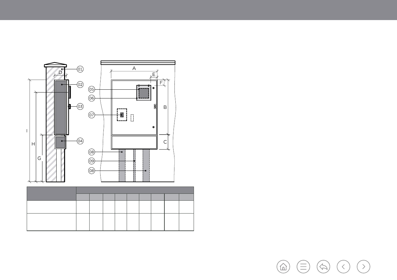
Figure K.69 

Typical arrangement for tariff metering cabinet recessed within compound wall

Type of kWh metering

Dimensions (mm)
A

B

C

D

E

F

G

H

I

Direct connected metering
(Up to 125 A)

600

800

250 200 60

60

800 

(min.)

1,600 

(max.)

1,800 

(max.)

CT. Operated metering
(5 A meter and CT ratio up 

to 400/5 A)

800

1,000 300 250 80

80

800 

(min.)

1,600 

(max.)

1,800 

(max.)

Key

01: Compound wall.
02: Weatherproof (IP 55) metering cabinet.

03: Hinged door with provision for wire sealing and pad locking (hole size: min. 10 mm diameter).

04: Cable (gland) box.

05: Transparent meter viewing window (min. 5 mm thickness, size: 150 mm × 150 mm).
06: Protection cover with hinges on top (size: 200 mm × 200 mm).

07: Position of incomer breaker.
08: 150/100 mm PVC pipe sleeve for service cable.
09: Conduit/s for earthing conductors (ECC).

For CT operated meters, VT fuses shall be sealed type, located in a sealable enclosure.

All tariff metering shall be smart meters, normally provided by DEWA and restricted 

to one for each consumer installation, unless otherwise approved/specified by 

DEWA.

K.9.1.5.2  CT metering requirements

Metering by means of current transformers (CTs) shall be installed where the circuit 

breaker rating at the point of supply is 160 A and above. 

NOTE 1: DEWA provides the smart kWh meter(s) and associated CTs for all tariff 

metering. In some circumstances the consumer might be permitted to provide the 

kWh meter and CTs as private check meters for energy monitoring purposes.

Refer to 

G.4.5

 for further details and requirements for CT metering. 

Dubai Building Code

Part K: Villas

K 102

K.9.1.6 

Ambient design conditions

All equipment, apparatus, materials and accessories used in electrical installations 

shall be suitable for the purpose intended. They shall be capable of operating with 

satisfactory performance in the climatic conditions described in Table K.30.

Parameter

Condition

Altitude:

Sea level (coastal)

Maximum outdoor ambient temperature (shade): 48 °C
Minimum ambient air temperature

2.8 °C

Maximum ambient air temperature

48 °C

Maximum average temperature over 24 h

37.8 °C

Maximum average temperature over 1 year

26.9 °C

Relative humidity

100% (max)

Thunderstorms per year

Occasional

Earthquake loading

0.07 g

Wind speed

45 m/s at 10 m height

Ground temperature

40 °C

Soil thermal resistivity

2.0 °C/m/w at depth of 0.9 m

NOTE: Heavy condensation and sandstorms also prevail

Table K.30 

Ambient design conditions for Dubai

K.9.1.7 

Cables and conductors

K.9.1.7.1  General

For general purposes and in normal situations, LSF/XLPE insulated, stranded copper 

conductor cables shall be used for all fixed wiring installations. The cables shall be 

appropriate to the building type and conform to the respective standard from the 

following list:
a)  BS 5467;
b)  BS 6004;
c)  BS 6724;
d)  BS 7211;
e)  BS 7629-1;
f)  BS 7846;
g)  BS 7889;
h)  BS 8436. 
In certain circumstances, PVC insulated cabling may be used for general purpose 

installations, subject to approval by DEWA.

In flammable/explosive situations, cables shall be selected to meet the requirements 

of UAE FLSC 

[Ref. K.1]

.

Flexible cables and cords for use in electrical installations shall be LSF insulated and 

sheathed, stranded copper conductors conforming to BS 7211. 
Cables for connection between ceiling roses and luminaires for pendant type light 

fittings and for enclosed luminaires shall be heat resistant silicone rubber insulated 

with stranded copper conductor conforming to BS EN 50525.

For elevators and similar applications, rubber insulated or PVC insulated flexible 

cables conforming to BS EN 50214 shall be used.
kWh meter tails shall normally be single core PVC insulated and sheathed cables 

conforming to BS 6004.

Dubai Building Code

Part K: Villas

K 103

The cables used for control, relays, instrument panels, etc. shall conform to BS 6231. 

Single core cables armoured with steel wire or tape shall not be used for AC circuits.

K.9.1.7.2  Minimum size of conductors 

The size of conductor used for lighting circuits shall be not less than 2.5 mm

2

.

The size of conductor used for utility sockets shall be not less than 4 mm

2

.

K.9.1.7.3  Current rating, size and voltage drop

All cables shall be adequately sized to continuously carry the normal current of the 

individual circuits based on various laying conditions as applicable and the maximum 

ambient temperature (BS 7769).
A typical selection of the cables recommended for villa and townhouse applications is 

shown in Table K.31, Table K.32 and Table K.33. 

Size of cables in concealed conduits

Max. rating of MCB/

MCCB (A)

Max. load current/

demand (A)

2 × 1C, single-phase 

(mm

2

)

3/4 × 1C, three-phase 

(mm

2

)

2.5

2.5

10/15

10/15

4

4

20

20

6

6

25

25

6

10

30

30

10

16

40

40

16

25

50

50

25

25

60

60

35

50

80

80

70

100

100

95

125

125

120

150/160

150/160

Table K.31  Typical recommended cable sizes – Single-core LSF insulated, non-armoured, stranded copper 

conductors

Size of one 3/4 C LSF/SWA/

LSF cable installed in normal 

situations (mm

2

)

Max. rating of MCB/MCCB (A)

Max. load current/demand (A)

2.5

10/15

10/15

4

20

20

6

30

30

10

40

40

16

50

50

25

60

60

35

80

80

50

100

100

70

125

125

65

160

160

120

180

180

150

200

200

185

250

250

240

300

300

300

350

350

400

400

400

Table K.32  Typical recommended cable sizes – Multicore armoured LSF insulated, copper conductors

Dubai Building Code

Part K: Villas

K 104

Table K.33  Typical recommended cable sizes – Multicore armoured XLPE insulated, copper conductors

Size of one cable installed in 

normal situations (mm

2

)

Max. rating of MCB/MCCB (A)

Max. load current/demand (A)

10

50

50

16

60

60

25

80

80

35

100

100

50

125

125

70

160

160

95

200

200

120

225

225

150

250

250

185

300

300

240

350

350

300

400

400

NOTE: The following process can be used to determine which cable size to select 

from Table K.31 to Table K.33.

a)  Assess initial demand with safe diversity and anticipated demand in future, if any, 

as applicable to individual circuits, for selection of cable size, breakers rating, etc.

b)  Assess individual fault levels and select MCBs/MCCBs accordingly.
c)  Refer to manufacturer’s catalogues and select MCBs/MCCBs, cable sizes, etc.  

for specific applications, considering inductive/capacitive loads, laying conditions, 

voltage drop, correction factors, etc.

The voltage drop from the point of supply to any point in the wiring installation shall 

be not more than 4% of the nominal voltage of the electric supply, unless otherwise 

specified.

K.9.1.7.4 

Cable colour identification 

The colour identification of insulated cable cores of unarmoured, armoured and 

flexible cables and of sleeve, band or disc of bare conductors shall be as indicated in 

Table K.34 and Table K.35.

Table K.34  Non-flexible cables and bare conductor identifiers

Table K.35  Flexible cables and cores colour identifiers

Function

Colour identification

Earth continuity conductor (ECC)

Green

and Yellow

Neutral conductor in single-phase and 

three-phase circuits (N)

Black

Phase conductor in single-phase circuits

Red

or

Red (R)

Yellow (Y)

Blue (B) as applicable

Phase conductor in three-phase circuits
R-phase

Red

Y-phase

Yellow

B-phase

Blue

Function

Colour identification

Live

Brown

Neutral

Blue

Earth

Green 

and Yellow

Dubai Building Code

Part K: Villas

K 105

K.9.1.8 

Wiring installation exposed to high temperatures

Any part of a wiring installation (such as the individual circuit cables, final 

connections to equipment, appliances and light fittings) shall be rated to maintain 

its performance at the temperatures likely to be encountered. Heat-resistant sleeves 

shall be provided for individual cores and/or heat-resistant cables.

For end connections to luminaries with incandescent and halogen lamps, and fixed 

heating appliances, heat-resistant sleeves and cables shall be rated for a minimum 

operating temperature of 85 °C.

K.9.1.9 

Wiring installations in hazardous areas

All light fittings, wiring accessories and other electrical equipment in potentially 

hazardous atmospheres shall be selected in accordance with BS EN 60079.

K.9.1.10  Load balancing 

In all cases where a three-phase supply is provided to a premises, the various 

categories of connected load such as lighting, socket outlets, water heaters, single-

phase air-conditioning units, equipment, apparatus, etc. shall be distributed and 

connected on red, yellow and blue phases as evenly as possible, to ensure load 

balance between the phases at all distribution levels.

K.9.1.11  Wiring accessories

K.9.1.11.1 

Conduits and fittings

High impact rigid PVC conduits and fittings shall conform to all relevant parts of BS 

4607, BS EN 60423 and BS EN 61386. They shall meet the following requirements:
a)  be suitable for use at a maximum ambient temperature of 48 °C;
b)  not soften or suffer structural degradation at a temperature of 70 °C;
c)  be non-hygroscopic; and
d)  be heat-resistant
PVC conduits shall be provided with copper/brass terminals.

Steel conduits and fittings shall conform to the relevant specifications in 


BS EN 60423 and BS EN 61386. They shall be hot-dip galvanized to class 4 

protection, both inside and outside. 

Flexible steel conduits and fittings shall conform to BS EN 61386. 

Conduit systems shall be designed and installed to exclude moisture, dust and dirt. 

Small drainage holes shall be provided at the lowest part of the system to avoid the 

accumulation of condensation. 

K.9.1.11.2  Trunking 

Where applicable, surface and underfloor (duct) trunking and their fittings shall 

conform to BS EN 50085. Trunking and fittings shall be constructed of steel, hot-

dip galvanized both inside and outside, or non-combustible insulating material 

with removable covers. Installation of the trunking shall be carried out strictly in 

accordance with the manufacturer’s guidelines.
The protective conductor shall run inside the trunking and not in parallel.

Internal fire barriers shall be provided where long run trunking crosses the floors/

walls. The requirements for fire barriers are specified in UAE FLSC 

[Ref. K.1]

.

Small insulated cables shall not be installed in perforated trunking.
Additional supports shall be provided where trunking changes direction.
Earth bonding shall be provided between sections/gaps in all trunking runs and 

bolted connections.

Dubai Building Code

Part K: Villas

K 106

K.9.1.11.3  Cable trays and supports

Cable trays, accessories and supports shall be either hot-dip galvanized  

or PVC-coated steel. Cable trays shall be either the perforated type or ladder type. 

They shall have sufficient strength and rigidity to support the cables installed, 


and be provided with upstands of adequate dimensions on both sides.

Cable tray systems, cable ladder systems and their fittings shall conform to 


BS EN 61537.

All fittings, bends, tees, elbows, couplers, etc. and supports shall be of substantial 

sections and of the same quality as the trays. Cables shall be fastened securely by 

purpose-made clips, cleats or saddles.
Earth bonding shall be provided between sections/gaps in all cable tray runs and 

bolted connections.

Internal fire barriers shall be provided where cable trays cross the floors/walls.

Small insulated cables shall not be installed in perforated cable trays.
Additional supports shall be provided where cable trays change direction or cable 

drops out of the cable tray.
Installation shall be carried out in accordance with 

G.4.17

.

K.9.1.12  Distribution boards and consumer units 

DBs and consumer units installed for connection of the final circuits within electrical 

installations shall be factory-built conforming to BS EN 61439/IEC 61439. An 

integral isolator shall be provided for isolation of the incoming supply.

The circuit breaker accessories, etc. shall conform to the standards specified.
Rewireable type fuses shall not be used in any wiring installation. Table K.36 may 

be used to indicate the preferred details and parameters of the equipment and 

components in DBs for an individual application.
Refer to 

G.4.12

 in the event of a MDB/SMDB being required. 

Parameter

Specification

I. Reference standards

BS EN 61439, BS EN 60947, IEC 61439

II. Rating of incoming supply breaker/isolation+

40 A [ ] 
60 A [ ]
100 A [ ]
125 A [ ]
.................... [ ]

(+On-load)

Breaker [ ] 
Isolator [ ]

III. Construction

1. Mounting

Wall [ ]
Pedestal [ ]
Surface [ ]
Recessed [ ]

2. Degree of protection of the enclosure for 

installation

Indoor-IP41/42 [ ] 
Outdoor-IP54/55 [ ]
...................................[ ]

3. Painting/finish (internal/external)

Stove enamelled [ ]
Epoxy [ ]
Polyester [ ]
Galvanized [ ]
...................................[ ]

4. Front cover (+neoprene)

Hinged [ ]
Bolted [ ]
Panel lock [ ]
Gasketted+ [ ]

5. Cable tray/conduit entry

Top [ ]
Bottom [ ]
Top and bottom [ ]

Table K.36  Specification of DBs

Dubai Building Code

Part K: Villas

K 107

Parameter

Specification

6. Assembly

Factory assembled [ ] 
...................................[ ]

IV. Internal layout/arrangement and fault 

training 

1. Segregation of live parts: 
Incoming supply terminals/lugs

Barrier [ ]
Shroud [ ]
Firmly secured [ ]
*Separately mounted and removable by tool [ ]

Busbar, tap-out connections and terminals 

(*Separate and independent of each other)

Barrier [ ] 
Firmly secured [ ]
*Separately mounted and removable by tool [ ]

Neutral and earth busbars and terminals

Separately mounted with adequate working 

clearances/spacing from incoming supply 

terminals/lugs [ ] and outgoing terminals of 

MCBs/FS [ ]

2. Arrangement of busbars and tap-out 

connections to outgoing circuit breakers/neutral 

busbars

Segregated for each:

Group of MCBs/TP ways [ ]   
ELCB Section [ ]      
Rigid, firmly secured, supported, direct and as 

short as possible [ ]
Adequately sized [ ]
Min. number of bolted joints [ ]
Min. number of looped connections [ ]

3. Rating/size of phase and neural busbars and 

terminals (at max. 50 °C ambient)

Rated for max. 70 °C internal ambient, consistent 

with the rated incoming supply breaker/isolator 

[ ]
Tinned electrolytic copper [ ]
...................................[ ]

Table K.36  Specification of DBs (continued)

Parameter

Specification

4. Min. fault rating of circuit breakers

6 kA (as per designed downstream short circuit 

current) [ ]

5. Provision of supports/facility for dressing 

clamping outgoing circuit cables

Channels [ ]
Trunking [ ]
..................... [ ]

6. Operational access/convenience for switchgear.
Incoming supply circuit breaker/isolator
Outgoing circuit breakers

Max. height 1.8 m (from FFL) [ ]
From outside of hinged door/bolted cover [ ]
Restricted/lockable [ ]

7. Maintenance access/replacement convenience 

for switchgear components

Breaker(s) [ ] 
Isolators [ ]
ELCB/s  [ ]
UV relays [ ]

8. Provision for termination of PVC/SWA/PVC/

XLPE/SWA/PVC cables

Gland plate [ ] 
Cable gland [ ]

9. ELCBs/RCCBs

Window A/C [ ] 
Split A/C [ ]
Lighting [ ]
Small power [ ]
Others..................... [ ]

10. UV Relays with auto-reset timer

Window A/C [ ]
Split A/C [ ]
Others.................... [ ]

V. Identification 

1. Rating of incoming supply and outgoing circuit 

breakers:

(For details of the specified rating – refer to 

approved SLD/distribution schedules)

Thermal [ ]
Fault [ ]
Discrimination [ ]

Dubai Building Code

Part K: Villas

K 108

Parameter

Specification

Type of circuit breakers: Incoming Outgoing (C/L-

Current Limit)

Isolator [ ] 
MCCB [ ]
C/L MCCB [ ]
C/L MCCB [ ]
F/S [ ]
C/L [ ]
For general loads, Type 1/L[ ]
For motor load, Type 2/G [ ]

2. Colour codes for internal, main circuits wiring:
Phase
Neutral
Earth

Red/yellow/blue [ ]
Black [ ]
Green and yellow [ ]

3. Terminal ferrules for control/auxiliary circuits

Indicating instruments [ ]
Others..................... [ ]

4. Permanent labels, engraved, “trafolite” or 

similar

Board designation [ ]
Controls [ ] 
Circuit designation [ ] 
Indications [ ] 
Warning notice(s) [ ]
ELCB/UV relay section [ ]

VI. Earthing

Compliance with K.9.1.18..................... [ ]

1. Rating/size of earth busbar and terminals

Adequate, consistent with the min. fault rating 

specified under IV.4 [ ]

Adequate no. and size to terminate main and 

circuits ECCs [ ]

2. Earthing of conductive parts

Enclosure [ ] 
Hinged door [ ]
Cable glands [ ]

3. Termination of ECCs

Copper lugs [ ]

Table K.36  Specification of DBs (continued)

Parameter

Specification

VII. Tests/certification

1. Type test
2. Routine tests and checks: 
Visual checks
Screwed/bolted connections;
Operational checks
Dielectric test

As specified by the Consultants/Owner [ ]
Certificate for review/reference [ ]
Compliance with specifications [ ]
Tightness [ ]
Mechanical/electrical [ ]
2,500/2,125 V (85%) [ ]

Dubai Building Code

Part K: Villas

K 109

K.9.1.13  Apparatus and accessories

K.9.1.13.1  Switches

Switches provided for local isolation of electric supply to individual apparatus and/or 

circuits shall conform to BS EN 60669. The rating of the switches shall be selected 

based on individual applications, such as for resistive or inductive loads. The current 

rating shall be not less than 5 A.
Switches installed for control of discharge lighting shall have a minimum current 

rating that is twice the steady state continuous current of the circuits.

For large groups of lighting, a gang switch shall be provided with a phase barrier 

inside the switch boxes.

For outdoor locations, switches with weather protection in accordance with IP55 shall 

be used.

For areas with a high risk of fire or explosion, gas sealed switches conforming 


to BS EN 60079 shall be used.

For appliances rated 20 A and above, and where visual indication of the presence 


of power is desired, a DP switch with neon indicator shall be provided.

K.9.1.13.2  Plugs and socket outlets

Single-phase plugs and socket outlets used in domestic installations shall conform to 

BS 1363. The socket outlets shall be of the type illustrated in Figure K.70.

Figure K.70  Typical 3-pin flat, double-pole, shuttered, switched twin socket 

15 A plugs and socket outlets used in domestic installations shall conform to BS 546.
Shaver socket outlets shall conform to:
a)  BS EN 61558 in bathrooms; and
b)  BS 4573 in rooms other than bathrooms.

Dubai Building Code

Part K: Villas

K 110

Industrial plugs and socket outlets shall conform to BS EN 60309. They shall feature 

a switch that is integrally built in or attached to it. The rating and type of socket 

outlets with plugs shall be selected to suit individual applications and shall not be 

interchanged for different current ratings.
Weather protected type (IP55) socket outlets shall be used for outdoor applications.

K.9.1.13.3  Arc fault detection devices (AFDDs)

Additional protection to mitigate the risk of fire due to arcing is recommended in 

certain applications. AFDDs protect against series and parallel arcing by detecting 

low-level hazardous arcing that circuit breakers, fuses and RCDs are not designed  

to detect. 

AFDDs shall be selected in accordance with BS EN 62606. An AFDD shall be placed 

at the origin of the circuit to be protected.

AFDDs are available in the following types:

a) 

one single device, comprising an AFD unit and opening means, intended to be 

connected in series with a suitable short circuit protective device declared by the 

manufacturer as conforming to one or more of the following standards:
1)  BS EN 60898-1;
2)  BS EN 61009-1; or
3)  BS EN 60269 series;

b) 

one single device, comprising an AFD unit integrated in a protective device 

conforming to one or more of the following standards:
1)  BS EN 60898-1;
2)  BS EN 61008-1;
3)  BS EN 61009-1; or
4)  BS EN 62423;

c) 

an AFD unit (add-on module) and a declared protective device, intended to be 

assembled on-site.

Examples of where such devices can be used include:
1)  premises with sleeping accommodation;
2) 

locations with a risk of fire due to the nature of processed or stored materials;

3)  locations with combustible construction materials;
4) 

structures having fire propagating features; and

5)  locations with endangered or irreplaceable objects (such as museums, libraries, 

art galleries).

K.9.1.13.4  Cooker control units

All stationary cooking appliances in domestic premises shall have a cooker control 

switch. The switch shall conform to BS 4177 and be located separate from the 

appliance (see Figure K.71). The cooking appliance shall incorporate an integral 

earthing terminal.
The cooker control switch shall be two-pole (for a single-phase appliance)  

or four-pole (for a three-phase appliance). It shall be connected to a separate final 

sub-circuit from the DB, through a 100 mA ELCB.

Dubai Building Code

Part K: Villas

K 111

Figure K.71 

Cooker control unit installed within 2 m of appliance (© Institution of Engineering and Technology. 

Figure based on Figure 4.4 in Institution of Engineering and Technology, 2018. Electrician’s guide to the building 

regulations 

[Ref. K.29]

)

Key

01: Control switch to be located within 2 m from controlled appliance

02: Electric hob

03: Electric oven

04: Consumer unit

Cooker control units incorporating a general purpose socket outlet shall be avoided, 

to allow grouping of socket outlet circuits in a separate 30 mA RCD/ELCB section.

The breaker rating and wire size shall be selected to be compatible with the 

connected load of the appliance.

K.9.1.13.5  Kitchen appliances 

Electrical appliances used in consumer installations (such as water heaters, cookers, 

hot plates, etc.) shall generally conform to BS EN 60335. Figure K.72 illustrates the 

typical setting-out details of a kitchen.

Figure K.72 

Cooker and kitchen typical installation 

setting out details (© Institution of Engineering 

and Technology. Figure based on Figure 5.2.2 in 

Institution of Engineering and Technology, 2018. 

Electrician’s guide to the building regulations  

[Ref. K.29]

)

Key

01: No sockets within 300 

mm of edge of sink

02: No sockets or accessories 

above gas or electric hobs

03: Cooker switch

04: Dishwasher

05: Fridge

06: Cooker connection

Dubai Building Code

Part K: Villas

K 112

K.9.1.13.6  Control of water heaters, saunas, Jacuzzis and washing machines

Double-pole switches with neon indicator shall be provided, appropriately rated for 

control of the equipment. The final connection to the equipment shall be made from 

a flex outlet plate. The plate shall be mounted adjacent to the equipment. 
For water heaters installed in a bathroom or water closet, the control switch shall be 

installed immediately outside the room. For saunas and Jacuzzis, the control gear 

shall be placed outside the sauna room/cabin.
Water heaters, saunas, Jacuzzis and washing machines shall be connected  

to a separate final sub circuit from the DB. 

Water heaters shall incorporate an integral earthing terminal adjacent to the phase 

and neutral terminals. All terminals shall be housed in a suitable recess with a splash 

proof removable cover. Every heater circuit shall be protected by a  

30 mA RCCB/ELCB.

K.9.1.13.7  Control of air-conditioning unit/equipment 

For other room air-conditioning units other than window type, a double-pole switch 

of appropriate rating, with flex outlet, shall be provided and mounted adjacent to the 

unit. 

Each room air-conditioning unit shall be connected to a separate final sub-circuit 

from the DB.
A maximum of two window type air-conditioning units are permitted to connect on a 

single-phase supply. Where three or more window type units are installed, they shall 

be balanced as evenly as possible over a three-phase supply.
The breaker rating and wire size shall be selected based on the connected load of the 

air-conditioning unit, subject to minimum 20 A with 4 mm

2

 circuit wires.

K.9.1.13.8  Extra LV safety apparatus

Extra-LV safety apparatus includes:

a)  electric buzzers and bells;
b)  mirror lights and shaver socket outlets in bathrooms;
c) 

light fittings for underwater installations.

Extra LV safety apparatus shall incorporate an appropriately rated double wound 

safety isolation transformer. The transformer shall either be integral or mounted 

separately. A cartridge fuse or MCB shall be incorporated in the secondary circuit. 

The safety isolation transformer shall conform to BS EN 61558. Segregation  

of LV and extra-LV circuits shall be in accordance with K.9.1.17.3.

K.9.1.13.9  Electric motors and starters

Control of electric motors shall conform to BS EN 60204 where the equipment  

is within the scope of the standard.
All motors shall be protected against overload, short circuit and earth leakage.  

They shall also be protected against voltage fluctuations and the loss of one or more 

phases, as necessary for the individual application.
Every motor having a rating exceeding 0.37 kW shall be provided with control 

equipment incorporating means of protection against overload of the motor. 
Only the installation of single-phase motors rated up to 3.7 kW, and three-phase 

motors up to 110 kW, is permitted, unless otherwise approved by DEWA. Where 

multiple motors above 110 kW are proposed, the advice of DEWA shall be sought on 

obtaining a bulk supply.
Starters shall be provided with overload relays of the thermal type. Relays shall have 

automatic compensation for variations in ambient temperature between 28 °C and 

48 °C.

Dubai Building Code

Part K: Villas

K 113

Starting equipment to limit current shall consist of any 

of the following: 
a)  adjustable speed drive;
b)  intelligent controllers;
c)  another type of device approved by DEWA.
All motors shall be provided with an isolator, to isolate 

the motor from the supply during inspection and 

maintenance. The isolator shall interrupt the supply on 

all phases. The isolator may be integral with the control 

gear or separate but shall be in close proximity to the 

motor. The control gear shall incorporate emergency 

stop pushbutton(s).
When motor starting gear is energized from an 

auxiliary circuit, the auxiliary circuit shall also be 

isolated during inspection and maintenance.
All starters, isolators and pushbuttons  

(see Figure K.73) shall be clearly marked in Arabic and 

English stating which machine they control and their 

function. To avoid confusion, the words “START” and 

“STOP” shall be used (and not “OPEN” and “CLOSED”).

Figure K.73 

Push buttons 

Motors and their control gear shall be located in well-

ventilated areas with adequate space for operation, 

inspection and maintenance.

K.9.1.14  Standby generators

If the permanent installation of a standby generator is 

required, it shall meet the requirements in 

G.4.14

K.9.1.15  Assessment of connected load and 

maximum demand 

K.9.1.15.1  Lighting and small power circuits

All lighting and fan circuits shall be installed as follows:
a)  maximum load per circuit of 2,000 W;
b)  minimum circuit wire/EEC size of 2.5 mm

2

 LSF 

copper, with maximum circuit breaker protection of 

16 A.

If light fixtures are not selected at design stage, a 

minimum of 100 W shall be used for each normal 

lighting and fan point. Fluorescent lamps shall be 

assessed as 1.8 times the lamp wattage.

Wherever fittings with discharge light, compact 

fluorescent lamps or low-volt lamps are installed, 

the circuit breaker rating, circuit conductor sizes and 

number of fittings shall be selected based on the actual 

load, including losses, for the specific application. 

Prior approval from DEWA shall be obtained for every 

installation.

Dubai Building Code

Part K: Villas

K 114

A radial final sub-circuit shall be installed to serve a maximum of five 13 A switched 

socket outlets in rooms other than the kitchen. It shall be controlled by a 20 A circuit 

breaker in the DB. A maximum of ten socket outlets in rooms other than the kitchen 

shall be connected to a ring circuit, controlled by a 30 A circuit breaker.
A current demand of 13 A shall be assumed for each 13 A switched socket outlet 

circuit. A minimum of 200 W per point shall be considered for each 13 A switched 

socket outlet, installed for general utility purpose, other than the kitchen. All twin 

socket outlets shall be taken to be as two separate socket outlet points. Kitchen areas 

might need separate circuits.
A current demand of 15 A shall be assumed for each 15 A switched socket outlet 

circuit. However, for general purpose utility socket outlets, an assumed load of 1,000 

W per socket outlet installed in commercial and industrial premises, and 500 W per 

socket outlet in residential premises, is permitted.

For stationary appliances and equipment, including air-conditioners, the actual load 

of each appliance and equipment shall be taken to be a connected load.

The current demand of specific equipment such as an electric clock, and other 

current-using equipment with a maximum rating of 5 VA, may be omitted from the 

assessment of load.
The assumed connected load of additional spaces/circuits shall also be indicated in 

the load distribution schedules submitted for DEWA’s approval (see K.9.1.15.2).

K.9.1.15.2  Maximum demand

All DBs shall be rated for the TCL before a demand factor is applied.
The demand load of each final sub-circuit is determined by adding the actual or 

assumed load of individual points/appliance/equipment, whichever is higher. An 

allowance for diversity shall be applied where appropriate.
The details of load distribution schedules shall be submitted for DEWA’s approval in 

the format identified in Table K.37 to Table K.40. The TCL of individual distribution 

levels/circuits shall be determined as recommended in K.9.1.15. An appropriate 

demand factor worked out by a qualified electrical Engineer is permitted, to 

determine the maximum demand at the main or submain distribution level.

Dubai Building Code

Part K: Villas

K 115

DETAILS OF CONNECTED LOAD, MAX. DEMAND & kWh METERING

PROJECT: 

BUILDING/ ________

OWNER:

AREA:

PLANNED COMPLETION DATE:

CONSULTANT:

PLOT NO.:

LVP/MDB/SMDB ______ (OF) _______  

LOCATION OF LVP/MDB:

CIRCUIT/ 

FEEDER


SMDB/DB 

NO.

1-PH/


3-PH

ACB/ 

MCCB/ 

ISOLATOR


RATING 

(A)

FAULT


DUTY 

kA

CABLE SIZE, TYPE 


AND 

NO. OF CORES

ECC 

SIZE 


1C, 

mm

2

LENGTH 

OF 


CABLE


(m)

CONNECTED LOAD


(kW)

TOTAL 

CONNECTED 

/INSTALLED 

LOAD


(TCL)


kW

MAX. 

DEMAND/ 

OPERATIONAL 

LOAD


(MDL)


kW

PROPOSED TYPE & NO. 

OF kWh METERS

REMARKS

NO. OF 

CORES 

1C/2C/ 

4C

TYPE 

XLPE/

PVC/

SWA

SIZE

R-PH


kW

Y-PH


kW

B-PH


kW

1-PH


(1)

3-PH


(2)

* LV/ 

HV


CT 

(3)

Incomer:
Out going:

MDB CONNECTED TO: DEWA LV/DB TRANSFORMER 

SMDB CONNECTED TO: MDB….. 


TOTAL CONNECTED LOAD 

PER PHASE: 


TOTAL:

DEMAND FACTOR:

MAX. DEMAND: ______ kW

* OVERALL TOTAL CONNECTED/INSTALLED LOAD (TCL): __________kW

TOTAL BUILT-UP AREA:

CONSULTANT/CONTRACTOR:  

TEL:

FAX:

* TCL - shall include all loads proposed to be installed including standby, spare and future load provisions..


Type of meter (rating of incomer): (1) Up to 60 A (2) Up to 125 A (3) LV CT … / … A        /HV CT … / … A (* 200/5 Amps CT metering)

(1)Phase

(3)Phase

Table K.37 

Typical details of connected load, maximum demand and kWh metering schedule

Dubai Building Code

Part K: Villas

K 116

LOAD DISTRIBUTION SCHEDULE (1-Phase)

PROJECT:

BUILDING/ ______

LOCATION OF DB:   

DB No.:
FED FROM:

MDB/SMDB ________/ METER ENCLOSURE

RA

TING

 OF


INC

OME

R

RA

TING

 OF

 E

LCB

SL

. No.

CIR

. No.

MCB R

TG. IN


AMP

S

CCT WIRE SIZE


mm

2

EC

C WIRE SIZE


mm

2

ROOM/

AREA

CONNECTED LOADS/POINTS  


W

ATT

/UNIT

LOAD PER 


CIRCUIT - WATT

RE

MARK

S

LTG

C.

 FAN

EX

. F

AN

SH.

 S

/O

13 A S

/O

W/

H

H/D

COOKE

R

15 A S

/O

'W

'  A

/C

'S'  A

/C

W

AT

. PUMP

R

Y

B

1

C1

2

C2

3

C3

4

C4

5

C5

6

C6

7

C7

8

C8

9

C9

TOTAL

CABLE SIZE: 1x 2/3/4C…

mm

2

 Cu. PVC/XLPE/SWA/PVC +1 X 1C,….

mm

2

 Cu. PVC, ECC   

C. fan = ceiling fan, ex. Fan = exhaust fan, sh. S/o = shaver socket - outlet

OR

CABLE SIZE: 2 x 1C…

mm

2

 Cu. PVC +1 X 1C,…. 

mm

2

 Cu. PVC, ECC

W/h = water heater, h/d = hair dryer, 'w' = window type & 's' = split type   

Table K.38 

Typical load distribution schedule

Dubai Building Code

Part K: Villas

K 117

TYPICAL CONNECTED LOAD/POINTS SCHEDULE 

LOCATION OF DB:

LOAD:

SCHEDULE:

RA

TING

 OF


INC

OME

R

RA

TING

 OF

 E

LCB

SL

. No.

CIR

. No.

MCB R

TG IN AMP

S

CCT WIRE SIZE


mm

2

EC

C WIRE SIZE


mm

2

ROOM/

AREA

CONNECTED LOADS/POINTS  


W

ATT

/UNIT

LOAD CIRCUIT

RE

MARK

S

LTG

C_F

AN

EX_F

AN

SH

_S/

O

13A S.

S/

O

W/

H

H/D

COOKE

R

15A S. /

O

'W

' A

/C

'S' A

/C

W

AT

_PUMP

R

Y

B

1

R1

2

Y1

3

B1

4

R2

5

Y2

6

B2

7

R3

8

Y3

9

B3

10

R4

11

Y4

12

B4

13

R5

14

Y5

15

B5

16

R6

17

Y6

18

B6

TOTAL

CABLE 

+1X

mm

2

 Cu, G/Y PVC, ECC    C_

Fan,

Socket

OR

CABLE

X 1C,

mm

2

 Cu, G/Y PVC, ECC    W/H 

=

Split

Table K.39 

Typical connected load/points schedule

Dubai Building Code

Part K: Villas

K 118

DETAILS OF MAXIMUM CURRENT ON TRANSFORMER WITH CHILLER/MOTOR LOADS

PROJECT:

OWNER:

PLOT NUMBER:

AREA:

LV Panel No.:

Rating:

Sr. No.

Type of load 

(chiller, motor, etc.)

kW

No. of compressors 

per chiller

Starting current of 

one compressor/ 

motor

Full load current with all 

compressors/motors running 

+ other loads 

(A)

Max. current when largest compressor 

starts + all other compressors/motors 

and other loads running 

(A)

Remarks 

(model no., make, type 

of starter, etc.)

Total 

Table K.40 

Typical details of maximum current on transformer with chiller/motor loads

Dubai Building Code

Part K: Villas

K 119

Table K.41 gives the maximum demand permitted at a DB/consumer unit connected 

to DEWA’s supply for the distribution to individual premises without connecting large 

motor loads.

Table K.41  Limit of maximum demand loads

Item

Feeder/transformer rating (A)

Load (kW)

1

60 A – feeder

30

2

100 A – feeder

50

3

125 A – feeder

60

4

160 A – feeder

80

5

200 A – feeder

100

6

300 A – feeder

150

7

400 A – feeder

200

Other methods of establishing maximum demand are permitted, where calculated by 

a qualified electrical Engineer with a suitable degree of knowledge and experience of 

the diverse applications of a particular installation. The design method and proposed 

diversity at each level of the distribution shall be submitted to DEWA for approval. 

They shall also be clearly indicated in the design drawings and schedules submitted 

to DEWA.
Refer to 

G.4.16

 for greater load requirements.

K.9.1.16  Design criteria for the installation of conduits, trunking, trays and 

accessories

K.9.1.16.1  Trunking and conduits

Trunking and conduits shall be selected to meet the requirements of K.9.1.11.
Cable trunking may be used for housing single core LSF cables where the installation 

of conduits is difficult due to space limitations.

Surface exposed trunking and conduit installations shall, as far as possible, have 

straight runs with branches at right angles only.

Draw-in boxes shall be provided in all straight conduit runs exceeding 15 m. Conduit 

runs having 90° bends shall be provided with draw-in boxes for every two bends.
Trunking and conduit shall be completely installed before any cable is drawn in.
Draw-wires shall be provided in all concealed conduits (and ducts) with the ends 

left free at the outlet boxes for pulling the wiring cables. Permitted cable routes for 

concealed cables are illustrated in Figure K.74.

Figure K.74 

Permitted cable routes for concealed cables within walls with a depth of less than 50 mm (© 

Institution of Engineering and Technology. Figure based on Figure 2.3.3 in Institution of Engineering and 

Technology, 2018. Electrician’s guide to the building regulations 

[Ref. K.29]

)

Key

01: No protection 

needed

02: Protection 

required unless 

depth greater than 

50 mm

All the trunking and conduit runs shall be free from sharp edges and burrs 

throughout their lengths. Suitable grommets and bushes shall be provided at the 

terminal outlets.
Trunking and conduit runs shall be supported at regular intervals  

(see Table K.42 to Table K.44).

Dubai Building Code

Part K: Villas

K 120

Method of installation

Spacing of support (mm)
Steel

Rigid PVC

Horizontal

1,500

1,000

Vertical

1,800

1,200

Table K.42  Trunking – Maximum spacing of clips, cleats, saddles or supports

Method of installation

Spacing of support (mm)
Steel

Rigid PVC

Horizontal

1,200

1,000

Vertical

1,500

1,200

Table K.43  Conduit – Maximum spacing of clips, cleats, saddles or supports

Method of installation

Spacing of support (mm)
Overall diameter
20 mm to 40 mm

Overall diameter
>40 mm

Horizontal

350

600

Vertical

600

800

Table K.44  Armoured cables – Maximum spacing of clips, cleats, saddles or supports

Entries to trunking shall be placed to prevent the ingress of water and all dead 

ends shall be closed. Only unbroken lengths of trunking shall be used for crossing 

partitions and walls.

Where cable trunking passes through walls, floors or other barriers, it shall be 

provided with a continuous cover and an internal fire barrier where fire separation is 

specified for the premises.

The trunking shall be provided with separate compartments for the different types of 

circuits in the following situations:
a)  where a common cable trunking is used for housing both power and 

communication circuits; or

b)  for housing circuits operating at different voltages.
All bends, tees and other accessories of cable trunking shall be of substantial sections 

and of the same quality as the trunking itself.
The different sections of trunking shall be bonded by copper links although the 

trunking shall not be used as ECC.

The minimum internal radius of any bend or elbow fitting in a conduit shall be 2.5 

times the diameter of the conduit, as shown in Figure K.75.

Figure K.75  Minimum internal radius of conduit elbow fitting

Dubai Building Code

Part K: Villas

K 121

All terminal and intermediate ends of PVC conduits shall be firmly secured with 

suitable adhesives as recommended by the manufacturer.
Circuit wires, bunched and installed in vertical trunking runs, shall be clamped/

secured within the trunking at regular intervals not exceeding 2 m, and at the 

terminal ends.

Standard conduit boxes, draw-in boxes and mounting boxes of light fittings and 

appliances shall be fixed to the building structure independently of the wiring 

conduits.

All exposed threads, tool-marks or visible damage to the protective finish of the 

steel trunking and conduits shall be coated with zinc-rich paint immediately after 

installation.
Suitable expansion couplers shall be provided in all trunking and conduit runs at 

the expansion joints in the building structure. They shall also be provided at regular 

intervals in all runs exceeding 7 m in length or as recommended by the manufacturer.
Suitable purpose-made boxes with adaptors, ceiling roses, etc. shall be provided at all 

individual outlet points of the wiring installations.

Light fittings used to house tungsten filaments and halogen lamps shall be 

segregated protected by PVC sheathing and terminal outlet boxes so as to prevent 

degradation due to the associated high temperatures.
Conduit runs concealed within the building structure shall be provided with not less 

than 10 mm of screed cover.
When the trunking and conduit runs are installed with chases in the building 

structure, they shall be firmly fixed at regular intervals in accordance with the 

manufacturer’s recommendations, using purpose-made crimpers and/or saddles.

The standard conduit boxes, draw-in boxes, floor-outlet boxes, etc. shall be installed 

with the cover/lid flush with the outer finish of the building structure (see BS 4662, 

BS 5733, BS EN 61535).

Only flush-type switches, socket outlets and accessories shall be used for concealed 

wiring.

Where conduit and/or conduit fittings are attached to equipment, smooth bore male 

brass brushes and flanged coupling shall be used.

Except where provision is made for fastening, conduits shall be saddled to the 

structure of the building in accordance with the following:
1) 

within 150 mm of each terminal angle box, bend or other conduit fittings;

2) 

at maximum intervals of 1.5 m couplings and through fittings;

3)  at maximum intervals of 15 m couplings.
Through-type draw boxes shall be counted as part of a straight run conduit.
Non-metallic conduits shall not be used in the following locations and circumstances:
i)  where the conduit is exposed to outside ambient temperatures;
ii)   where the conduit is at risk of being affected by chemicals which cause 

deterioration in its construction;

iii)  plant rooms; 
iv)   elevator motor rooms;
v)  elevator shafts.
All conduit accessories shall be of substantial sections and of the same quality as the 

conduit itself.

K.9.1.16.2  Flexible conduits

Flexible conduits shall not be used for complete fixed wiring installations. They shall 

only be used as and where permitted.

A flexible conduit run shall be not more than 2.5 m in length.
Metallic flexible conduits may be used for connecting electrical motors and other 

equipment to the fixed wiring, subject to adjustment of position and vibration.

Dubai Building Code

Part K: Villas

K 122

Flexible conduits shall only be run exposed and shall be so positioned that they are 

not susceptible to mechanical damage. Wherever necessary, flexible conduits shall be 

supported in accordance with the manufacturer’s recommendations.

The end of flexible conduits shall be securely anchored to the fixed conduit or 

equipment to which it is attached. Approved flexible conduit adaptors shall be used 

that maintain effective mechanical continuity without distorting the conduit.

Flexible conduit shall not be used as part of the earth conductor. A separate earth 

conductor shall be installed to meet the same requirements for rigid conduit 

installation.

K.9.1.16.3  Cable trays

Trays for supporting cables shall be used in warehouses, industrial plant and 

equipment rooms, cable trenches, shafts in buildings, etc.
The type and material of the cable trays shall be selected to suit individual site 

locations and shall meet the relevant requirements specified in K.9.1.11.3.

The cable trays shall be supported at regular intervals with purpose-made supports 

(see Table K.43).

Cable trays installed in outdoor locations and in locations where cables are exposed 

to the sun shall be provided with sun-shade covers. Covers shall be secured to the 

trays, and adequate ventilation provided, in accordance with the manufacturer’s 

instructions.
Cables shall be fastened securely by purpose-made clips, cleats or saddles  

and spaced as shown in Table K.44. 

Cable ties shall not be used to support multicore cables installed on cable trays that 

are fitted vertically.

Cable trays shall not be used in locations where they are likely to be subjected to 

severe physical damage.

Sufficient space shall be provided and maintained around cable trays to permit access 

for installing and maintaining the cables without causing unnecessary damage. 

Vertical clearance above the tray shall be not less than 1.5 times the height of the 

tray, or as given in the cable and cable tray manufacturer’s recommendations. 
Cable trays shall be installed as complete systems with bends and other accessories. 

Each run of cable trays shall be completed before the installation of cables. All sharp 

edges, burrs and projection shall be removed, and the tray shall be finished smooth to 

prevent injury to cables.
Metallic cable trays shall not be used as an ECC, although sections shall be bonded 

using copper links.
Cable trays shall be installed in such a way as to provide ease of access to cables 

through the route.

K.9.1.17  Design criteria for the installation of cables, equipment, accessories 

and wiring systems

K.9.1.17.1  Armoured cables 

Armoured cables shall be installed in one of the following ways:
a)  directly buried in the ground;
b)  drawn through ducts;
c)  laid in concrete trenches;
d)  cleated to a wall;
e)  mounted on cable trays.
Cables shall be installed and used in association with other equipment in accordance 

with BS 7671. For environments or installations not explicitly described within this 

Part, the appropriate regulations and standards shall be observed.
The current-carrying capacity of cables shall be determined after applying suitable 

correction factors based on the installation method of the cables.

Dubai Building Code

Part K: Villas

K 123

Cables shall be selected ensuring voltage drops within the limit described in K.9.1.7.3 

and 

G.4.7.3

.

Only armoured cables shall be used for underground installations. Precautions shall 

be taken to avoid mechanical damage to the cables before and during installation. 

Cables shall be laid as shown in Figure K.76. Where protective covers are required, 

they shall be centred over the cables, throughout their length.
Where cables pass underneath driveways or roads, PVC-U ducts shall be provided 

with heavy-duty (HD) manhole covers. 

Cable routes shall be marked by cable route markers/marking tape, placed at 

maximum intervals of 10 m along straight runs and 2 m at deviations (see Figure 

K.77). Route markers shall indicate the voltage level in Arabic and English.

Figure K.76 

Typical armoured cable installation below ground

Key

01: Ground

02: Warning tape at 300 mm 

below ground

03: 50 mm overlap on either side

04: Armoured cable at 900 mm 

below ground

05: 150 mm impervious soil layer

Heavy-duty conduit shall be provided for motor connections, external applications 

and locations subject to vibration, risk of mechanical damage or exposure to 

moisture.

Cables shall be installed on cable trays at specific locations and as stipulated in 

K.9.1.11.

In the event of crossing or proximity of underground telecommunication cables 

and underground power cables, a minimum vertical clearance of 100 mm shall be 

maintained.

Figure K.77 

Typical cable route marker (DEWA)

Dubai Building Code

Part K: Villas

K 124

For cables in fixed wiring installations, the internal radius of the bend shall be not less 

than eight times the cable diameter (see Figure K.78).

Figure K.78 

Cable bending radius (Eland Cables)

No joints shall be included in any cable runs in the consumer’s fixed wiring 

installation.

Where cables or wiring systems pass through floors, walls, partitions or ceilings, the 

openings remaining after passage of the wiring systems shall be sealed by a listed fire 

stopping system to the degree of fire resistance required by UAE FLSC 

[Ref. K.1]

Cable glands used for armoured cables shall be of brass compression type, 

conforming to BS 6121, with earth tags and PVC shroud.
All terminations of cable conductors shall be mechanically and electrically sound. 

Terminations shall be made using a terminal or compression type socket/lug, 

approved by DEWA. Terminations shall not impose any mechanical strain on the 

terminal or socket/lug.

Separate ECCs shall be installed and terminated for each feeder/circuit, as specified 

in K.9.1.18.

Single core cable shall be arranged in trefoil formation. Non-ferrous cable gland plate 

shall be used for termination of single core armoured cables. The armour shall be 

earthed.
No cables shall run in an elevator or hoist shaft unless the cables are part of the 

elevator/hoist installation.

Dubai Building Code

Part K: Villas

K 125

K.9.1.17.2  Distribution boards

All DBs shall be installed in locations to which access is available at all times for 

operation, testing, inspection, maintenance and repair.
DBs shall not be installed in the following locations:
a)  bathrooms and toilets;
b)  damp or wet locations;
c)  bedrooms;
d)  kitchens;
e)  above sinks;
f)  store rooms;
g)  rooms with an ambient temperature exceeding the ambient design conditions of 

the equipment;

h)  dangerous or hazardous locations; or
i)  below any staircase.

DBs shall be selected and designed in accordance with K.9.1.12.

DBs shall incorporate means for isolation of mains supply in the form of either a 

circuit breaker or an incomer isolator, as applicable.

Every circuit breaker or fuse within the DB shall be identified and labelled to indicate 

the apparatus or circuit it controls. Table K.38 and Table K.39 show single-phase and 

three-phase DB schedules.

Incoming supply cable installed to any DB shall be segregated and identified from the 

outgoing circuit cables/wiring.

All DBs shall be installed flush or surface mounted at a maximum height of 2 m to 

the top of the DB as shown in Figure K.79.

Figure K.79 

Maximum DB mounting height diagram

Key

01: DB

02: FFL

2 m

01

02

K.9.1.17.3  Segregation of circuits, phases and wiring systems

All wiring and accessories shall be selected and installed to suit individual locations. 

They shall conform to K.9.1.11 and the following requirements. 

Circuits from different DBs shall not be installed in a common conduit or trunking.
The circuit wires of individual categories and of different voltage grades shall be 

installed in separate conduits, or segregated with barriers where installed in the same 

trunking run.
The circuit wires of individual categories (such as lighting, power and emergency) 

shall be segregated with barriers in trunking runs or installed in separate conduits.

Dubai Building Code

Part K: Villas

K 126

Where residential premises are supplied with a three-phase supply, the light fittings, 

socket outlets, water heaters, cookers and other single-phase apparatus in any 

room shall not be connected to more than one phase, unless this is unavoidable. If 

connection to more than one phase cannot be avoided, a minimum distance of  

2 m shall be maintained between outlets, accessories or appliances connected to 

different phases. 
Where a switch box contains more than one phase, for group switching, approved 

switch boxes with phase barriers shall be used and labelled to indicate that  

400 V is present within the box. All circuit wires shall be identified by colour as shown 

in Table K.34 and Table K.35. 

Where a wiring system is in close proximity to non-electrical services, the wiring 

system shall be segregated and protected against hazards that are likely to arise from 

the presence of the other service(s) in normal use. Provision shall be made for safe 

and adequate access to all parts of the wiring system which might require inspection, 

maintenance or replacement.

Switches controlling light fittings, water heaters, etc. shall not be installed in 

bathrooms. In kitchens and other areas where water is regularly used, switches shall 

not be mounted within 2 m of any water tap, wash basin or sink where possible. If 

there is insufficient space to allow for this, ceiling mounted, insulated, cord-operated 

switches shall be used.
Socket outlets shall not be installed in bathrooms.
A track system for luminaires shall conform to BS EN 60570.

K.9.1.17.4  Mounting heights of accessories

Accessories (as described in K.9.1.13) shall be mounted as follows (and as shown in 

Figure K.80).

a)  All lighting switches, DP switches of air-conditioning units and water heaters, 

ceiling fan regulators, shaver socket outlets, etc., provided as part of the electrical 

installation shall be mounted 1.25 m above FFL.

b)  13 A switched socket outlets used for general purpose shall be installed at 

450 mm above FFL. 13 A switched socket outlets provided in kitchens shall be 

installed 150 mm above the worktop. 

All switches shall be mounted in readily accessible positions.

Figure K.80 

Typical mounting heights of electrical accessories

1,250

450

150

Dubai Building Code

Part K: Villas

K 127

K.9.1.17.5 

Identification labels and notices

All sections of the consumer installation at the DBs shall be provided with 

identification labels to indicate the location and purpose of each protection device, 

piece of connected equipment and circuit. Instructions or caution notices for correct 

operation shall also be provided where necessary. All labels shall be in both English 

and Arabic as shown in Figure K.81. Font sizes shall be chosen to suit the individual 

application.

Figure K.81 

Typical electrical warning label

K.9.1.18  Earthing and earth leakage protection

K.9.1.18.1  General

Earthing systems shall be designed and installed in such a way that they remain safe 

and do not endanger the health and safety of persons or their surroundings. Every 

consumer installation shall be provided with a separate earthing system within the 

plot limits, installed and maintained by the consumer.
An earth system shall remain perform effective throughout the life of the plant. 

It is difficult in many cases to continuity check after installation; the system shall 

therefore be robust and protected from mechanical damage and corrosion where 

necessary.
Each consumer’s earthing system shall comprise the earth electrode(s) main earth 

lead conductor connected between the earth electrode(s) and the consumer’s main 

earthing terminal(s) or earth busbar.
ECCs shall be provided for every outgoing circuit from the DBs, equipotential bonding 

of all metalwork and exposed conductive parts and enclosures, etc. BS 7430, BS EN 

50522 and IEC 60364 shall be referred to for guidance.
Selection of the earthing conductor material shall be based on its compatibility with 

the material of the earth electrode. For a conductor installed in the ground, the 

corrosive effect of the soil shall also be taken into account.
The consumer’s earthing system shall be connected to the DEWA earthing system 

[either the incoming supply cable armour or the earth continuity conductor (ECC), as 

approved by DEWA].

The following shall have separate earthing networks and shall not be connected to 

the main electrical earthing system:
a) 

LV networks;

b) 

Extra LV networks;

c)  private generators;
d)  lightning protection systems.

Dubai Building Code

Part K: Villas

K 128

The earthing system shall be of low electrical resistance, good corrosion resistance, 

and able to dissipate high fault current repeatedly.

The consumer main earthing connection shall be a TN-S system (see Figure K.82). 

The exposed conductive parts of all the electrical equipment of the installation shall 

be connected by circuit ECCs to the main earthing terminal. The earth fault loop 

impedance shall be sufficiently low for the protective device (fuse, circuit breaker, 

RCD) to operate in the required time in the event of a fault to earth.

Figure K.82  Typical TN-S earthing arrangement (© British Standards Institute. Figure extracted from 


BS 7671:2018. Permission to reproduce extracts from British Standards is granted by BSI Standards Limited 

(BSI). No other use of this material is permitted.)

Key

01: Source of energy

02: Protective conductor (PE)

03: Consumers’ installations

04: Source earth

05: Equipment in installation

06: Exposed-conductive-parts

The neutral and earth conductors shall be kept separate. They shall not be connected 

together at the main earth terminal or at any other point in the consumer’s 

installation.

Foundation metalwork in concrete may be used as a ready made and effective earth 

electrode. The total electrode area formed by the underground metalwork of a large 

structure can be used to provide an earth resistance lower than that obtainable 

by other methods. It is important that consideration is given to the possibility of 

corrosion of the metalwork reinforcement. The products of corrosion occupy a 

greater volume than the original metal, and cracking might occur. 
Continuous earth currents shall be resolved by the designer of the electrical system. 

NOTE: A possible source of such current might be incompatible with other buried 

metalwork, including other types of earth electrode to which foundation metalwork 

could be bonded, such that it might be necessary to consider the need for cathodic 

protection.


Damage to the concrete in the form of cracking, due to arcing or the rapid 

evaporation of moisture, can occur where the long-term duration earth fault currents 

exceed the carrying capability of the electrode. This situation is unlikely to arise 

if the electrode has a resistance sufficiently low to avoid dangerous voltages to 

earth. Where, in structures made of bolted sections, the electrical continuity of the 

structural joints cannot be relied upon to form permanent and reliable earth bonds, it 

is necessary to install loops bonding across these joints.
Water mains shall not be used for earthing purposes. Metal pipes (e.g. for gas, oil, 

compressed air or drainage) carrying other services shall only be bonded to the 

protective conductors and not used for the sole means of earthing.
Earth electrodes shall not be installed close to a metal fence, unless they are used 

for earthing that fence. This is to avoid the possibility of the fence becoming live and 

thus dangerous at points remote from the substation, or alternatively giving rise to 

danger within the resistance area of the electrode by introducing a good connection 

with the general mass of the earth.

Dubai Building Code

Part K: Villas

K 129

K.9.1.18.2  Consumer’s main earth electrode

A minimum of one main earth electrode shall be provided for each incoming point of 

supply/consumer’s DB, within the consumer’s premises. For installations with a main 

incomer of 200 A and above, a minimum of two earth pits shall be provided.
The earthing systems shall consist of copper conductors or steel rods (austenitic 

steel or copper clad) of appropriate dimensions, set with a driving pin and head 

driven to a minimum depth of 3 m. The earth electrode shall be installed inside a 

300 mm × 300 mm × 300 mm earth pit with inspection cover. The connection of the 

earthing conductor to the earth electrode or other means of earthing shall be made 

using compound filled, encapsulated or substantial clamps of non-ferrous material. 

NOTE: Uncoated buried copper is electro-positive to uncoated buried steel. When 

interconnected by a current-carrying conductor, these metals form an electrochemical 

cell that can cause accelerated corrosion of steel. 

The consumer’s main earth electrode shall be installed within 1.5 m of the DB. Where 

more than one earth electrode is installed within the premises, they shall be spaced 

not less than 6 m apart. 
Apart from the risk of corrosion to the earthing system, the chemical treatment 

of soil has environmental implications and is not a long-term solution to meet a 

specified level of resistance. Coke breeze shall not be used due to its highly corrosive 

nature.

For each incoming DEWA supply/DB, the main earth electrode resistance shall not 

exceed 1 Ω.

The resistance from any point of the earth continuity conductor (ECC) to the main 

earth electrode shall not exceed 0.5 Ω.

The consumer’s earth electrode resistance and the continuity of ECCs shall be 

periodically checked and maintained to ensure consumer safety as outlined in  

BS 4444.

Lightning protection earthing, if required, shall be separate from the earthing of 

the incoming DEWA supply/MDBs. A minimum distance of 7 m shall be maintained 

between the earthing inspection pits.

K.9.1.18.3  Earth continuity conductor (ECC)

Every circuit in the MDBs, SMDBs and final DBs shall be provided with a separate 

green and yellow (G/Y) LSF insulated copper ECC. The minimum size of ECCs shall 

be selected as specified in Table K.45.

Cross-sectional area of phase/

neutral conductor (S) (mm

2

)

Minimum cross-sectional area 

of ECC (G/Y LSF insulated 

copper conductors) (mm

2

)

Minimum cross-sectional 

area of equipotential bonding 

conductors (mm

2

)

S ≤ 16

S

S/2
(not less than 6)

16 < S < 35

16

10

S > 35

S/2

S/4
(need not exceed 25)

Table K.45 

Minimum size of earth continuity cables (ECC)

ECCs shall be terminated with tinned copper lugs at both ends, on purpose-made 

earth terminals at:
a)  electrical equipment, apparatus and distribution switch gear;
b) 

light fittings; and

c)  mounting boxes of switches and socket outlets.
Joints shall be made such that their current-carrying capacity is not less than that of 

the conduit itself. Joints shall also have the same insulation, mechanical strength and 

protection properties as those of the wiring system or conduit of which they are part.

ECCs shall be covered with green and yellow LSF insulation and terminated with 

purpose-made lugs or fixings.

Dubai Building Code

Part K: Villas

K 130

Where associated with circuits, ECCs shall be labelled at their termination points with 

circuit identification numbers.

Circuit ECCs shall run alongside the associated phase and neutral conductor.
The following shall not be used as an ECC:
1)  gas pipes;
2)  oil pipes;
3) 

metallic conduit, support wires or other flexible metallic parts; or

4) 

construction elements other than metalwork as described in K.9.1.18.

ECCs shall be protected against mechanical and chemical deterioration and 

electrodynamics effects in accordance with the manufacturer’s requirements.
Where two ECCs are used, the ends of the ECC shall be terminated independently of 

each other at all connection points throughout the circuit, the DBs, junction boxes 

and socket outlets. To achieve this, an accessory shall be provided with two separate 

earth terminals.
Where the cable incorporates metallic armouring, this shall be clamped to the cable 

gland. The main earth conductors shall be placed such that the metallic cable sheaths 

are reliable and readily connected to it by bonds made to the cable gland.
Earthing conductors shall be accessible for the connection of any detachable earthing 

devices used with the electrical equipment.

K.9.1.18.4  Earth leakage protection

Earth leakage protection shall be designed and incorporated in consumer installations 

in accordance with BS EN 61140 and IEC 61140.

The ELCBs/RCCBs shall generally conform to BS EN 61008-1 and BS EN 61009-1. 

Recommended values of operating current of ELCBs/RCCBs are specified in Table 

K.46, though the designer shall verify with the manufacturer’s recommendations.

Serial. No. Circuit/equipment/apparatus

Rated operating current (mA)

1

13 A switched socket outlets

30

2

Water heater/coolers/dishwashers

30

3

Refrigerator/washing machine and similar apparatus

30

4

Domestic water pumps

30

5

Jacuzzi pups

10

6

Under water lighting

10

7

15 A switched socket outlets (general purpose)

30

8

General lighting

30/100

9

Flood lighting

100/300

10

Window/split type air conditioner

100

11

Fan coil/AHU/VAV

100

12

Package type air-conditioning unit

100/300

13

Chiller

100/500/1,000

14

Irrigation pump

100

15

Electric cooker

100

16

Industrial machine

100/300

17

Elevators/escalators/hoist

300/500

18

Neon sign

300

Table K.46  Recommended value of operating current for ELCB/RCCB in consumer installations

NOTE: Grouping of circuits under one ELCB/RCCB is permitted for lighting circuits, 

general purpose switched socket outlets, single-phase equipment/appliances, etc. 

The maximum number of circuits proposed under each group should be selected 

taking into account the building type and the possible interruptions.

Dubai Building Code

Part K: Villas

K 131

K.9.1.18.5  Equipotential bonding

All metalwork of the consumer’s installation, other than current-carrying parts, shall 

be provided with equipotential bonding conductors as shown in Figure K.83. This 

shall include:
a)  cable armour;
b)  metal conduits;
c)  metal cable tray/trunking sections;
d)  metal accessory boxes;
e)  exposed metalworks of consumers’ appliances;
f)  apparatus;
g)  equipment;
h)  machines;
i)  building structures;
j)  metallic enclosures and parts;
k)  metal water pipes.

Figure K.83 

Typical example of main equipotential bonding of services (© Institution of Engineering and 

Technology. Figure based on Figure 5.6 in Guidance Note 8: Earthing and Bonding 

[Ref. K.30]

)

Key

01: Other extraneous conductive part

02: Water installation pipe

03: Circuit protective conductors

04: Gas installation pipe

05: Main protective bonding conductors

06: Earthing conductor

07: Means of earthing

Dubai Building Code

Part K: Villas

K 132

The cross-sectional area of equipotential bonding conductors shall be selected using 

Table K.45.

A main protective bonding conductor shall have a minimum cross-sectional area not 

less than half the cross-sectional area required for ECC of the installation, and not 

less than 6 mm

2

. The cross-sectional area need not exceed 25 mm

2

 if the bonding 

conductor is of copper or a cross-sectional area affording equivalent conductance in 

other metals.
The equipotential bonding conductors shall be connected to the main earthing 

terminal within the consumer’s wiring installations. The continuity shall be tested and 

maintained by the consumer.

K.9.2 

Electrical vehicle charging points 

Electrical vehicle charging points should conform to 

G.5

K.9.3 

Renewable energy

K.9.3.1 

General

As a type of renewable energy, solar energy is clean and secure. DEWA encourages 

the use of solar energy to reduce reliance on traditional energy sources (such as gas, 

oil and coal), which are diminishing.
Where a building incorporates on-site generation of electricity from a solar 

photovoltaic system, it can be a solar grid-connected system or a solar off-grid 

system. Grid-connected solar generators shall be connected to the DEWA network, 

operated and maintained according to DEWA regulations.

For off-grid solar system, the backup off-grid allowed for emergency load shall be 

indicated in the TCL along with the grid-based battery charger load, if applicable.

Connection of solar PV systems/distributed renewable resource generation (DRRG) 

to the DEWA grid shall be subject to DEWA approval. 

The designer shall refer to DEWA specifications, acceptable standards, procedures 

and other requirements as published on the DEWA website (Shams Dubai section), 

which are updated regularly and form an integral part of DBC.

Solar power generation systems shall conform to K.9.3 and to Section 2, Ch. 14 of 

UAE FLSC 

[Ref. K.1]

Building attached photovoltaic (BAPV) systems attached to roofs, excluding curved 

or special roofs, are permitted to achieve a minimum fire classification of Class C 

when tested in accordance with Section 2.2.4, Ch. 14 of the UAE FLSC 

[Ref. K.1]

The minimum fire classification permitted for building integrated photovoltaics 

(BIPV) and BAPV systems other than the above shall be confirmed with DEWA and 

DCD upon commencement of design.

K.9.3.2 

System documentation requirements

Consultants and Contractors registered with DEWA for activities related to grid-

connected solar PV systems (DRRG Solar PV Consultants and DRRG Solar PV 

Contractors) shall refer to DEWA guidelines published on the DEWA website for this 

requirement. Applications for solar connections shall be submitted online and shall 

include the following documents:
a)  basic system information;
b)  details of the system designer information; and
c)  details of the system installer, operation and maintenance procedure.


Content      ..     25      26      27      28     ..