Dubai Building Code (2021) - page 22
 

  Index      Manuals     Dubai Building Code (2021)


Search            copyright infringement  


Content      ..     20      21      22      23     ..


Dubai Building Code (2021) - page 22


Dubai Building Code

Part H: Indoor environment

H 64

H.6.2.6 

Sanitary plumbing acoustic requirements

The sanitation system shall be designed and routed through the building with 

attention to the acoustic requirements of the space that it passes through. Acoustic 

insulation shall be provided where required.

H.6.2.7 

Rodding eyes

To provide effective access for maintenance and cleaning, rodding eyes shall be 

installed:
a)  at the start of all horizontal runs in sanitation pipework; and 
b)  at changes of direction in any sanitation pipework. 

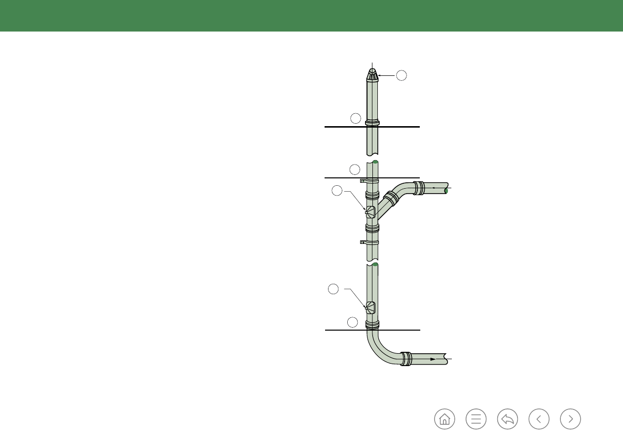
Access junctions (see Figure H.17) shall be installed in discharge stacks at every 

storey level to provide access to clear blockages. 
All rodding eyes shall terminate above the spill-over level of the appliance. 

Figure H.17 

Drainage discharge stack detail illustrating rodding eye and vertical access junction locations

01

02

03

04

04

05

Key

01: Vent cowl

02: Roof level

03: Typ. floor levels

04: Access covers

05: Ground floor level

Dubai Building Code

Part H: Indoor environment

H 65

H.6.2.8 

Sanitation pipework

All internal pipework shall be manufactured from PVC-U in accordance with  

BS EN 1329-1. Waste pipework shall conform to BS 5255 and BS EN 1329-1.

The size of the sanitary fitting outlet connections installed within the sanitation 

system shall be not less than the minimum shown in Table H.9.

Sanitary fitting

Minimum outlet size (mm)

Water closet

100

Wash basin

32

Kitchen sink

40

Floor drain

75

Bath tub/shower

40

Washing machine

40

Balcony drain

50

Table H.9  Minimum sanitary fitting outlet sizes

The size of the pipework shall be not less than the minimum shown in Table H.10 for 

buildings up to seven storeys in height, and in Table H.11 for buildings of more than 

seven storeys.

Pipework system

Minimum pipe size (mm)

Soil vent pipe

100

Waste vent pipe

100

Rainwater pipe

100

Vent pipe

75

Balcony drain

50

AC drain pipe

32

Table H.10 

Minimum drainage pipework sizes for buildings up to seven storeys

Pipework system 

Minimum pipe size (mm)

Soil vent pipe

150

Waste vent pipe

150

Rainwater pipe

100

Vent pipe

100

Balcony drain

50

AC drain pipe

32

Table H.11 

Minimum drainage pipework sizes for buildings above seven storeys

Only long radius fittings shall be used in the wet portion of any discharge stack. 

Thermoplastic drainage pipework shall not run through electrical rooms, electric sub-

stations, prayer rooms, kitchens, kitchen food stores and bedrooms. 
Drainpipes shall not be cast into a building structural element without prior approval 

from the Structural Engineer at the Authority.
Where drainage pipework is required to pass through a structural element in a 

building, a cast iron sleeve shall first be fitted within the structural element to allow 

the drain to pass through. The sleeve shall offer a tolerance of at least 50 mm to 

simplify the installation of the pipe. The gap between the pipe and the sleeve shall 

then be filled with suitable sealant. 

The routing of drainage pipework through sensitive areas of a building should be 

avoided. Sensitive areas might include, but are not limited to, the following:
a) 

areas of architectural significance;

b)  pipework routes through areas of different ownership or tenancy; and 
c)  areas where access to drainage pipework might be restricted. 

Dubai Building Code

Part H: Indoor environment

H 66

Where routing drainage pipework through these areas cannot be avoided, the 

pipework installation shall be configured to mitigate the risk of pipework leaks. 


This shall be achieved by using pipework materials that have limited pipework joints, 

or “pipe in pipe” installation techniques.

H.6.2.9 

Leak detection systems

Leak detection systems shall be installed in areas of a building where an undetected 

water or drainage leak could affect sensitive equipment or cause significant damage 

to the building and its interior (e.g. electrical communication rooms, base of 

mechanical services risers, floor voids and some plant room areas). The requirement 

for and extent of leak detection systems will depend on the building occupancy or 

use. 
To enable an automatic warning signal to be sent to the BMS, all leak detection 

systems shall be wired to a dedicated control panel which incorporates  

volt-free contacts. 

H.6.3 

Below-ground drainage

H.6.3.1 

Drainage systems

Below-ground drainage systems shall be designed in accordance with BS EN 752  

to receive soil and waste flows from the above-ground sanitation system.
Foul water flows shall be collected and conveyed to the external drainage network 


by gravity flow.
Buried drainage pipework, fittings and ring seal joints shall be specified to suit the 

ground conditions in which they are installed and the nature of the discharge they 

receive. 

Drainpipe sizes and gradients shall be selected based on the calculated flows through 

the drainage system. In all instances, self-cleansing velocity shall be achieved through 

each drain section. The drainage design and associated calculations shall be issued to 

the Authority for approval. 
Drainage pipe connections shall be airtight and free from any internal obstructions. 

Pipe bedding and surround materials shall be selected to suit the prevailing 

geotechnical ground conditions. All drainpipe bedding and backfilling materials shall 

be installed in accordance with the specified pipework manufacturer’s requirements. 

Drainpipes shall not be routed through ducts, bridges or their associated foundations. 

Where drains are required to pass through a building structural element, they shall be 

encased within a cast iron sleeve. The sleeve shall be sized to allow the drain to safely 

pass through. The gap between the pipe and the sleeve shall be filled with a suitable 

sealant. 

If an underground drainpipe line is installed less than 600 mm below finished floor 

level, it shall be provided with 150 mm thick concrete encasement. 

Underground drainage pipework and fittings shall conform to BS EN 13476.
Refer to the Authority drainage details for confirmation of approved manhole, 

inspection chamber, pipe bedding, gully and pipe connection arrangements.
Commercial and industrial waste shall not be drained into the public drainage 

network unless approved by the Authority. Approval will only be granted if the 

appropriate equipment is available for the initial treatment of the waste.

Dubai Building Code

Part H: Indoor environment

H 67

H.6.3.2 

Access to drainage systems

Means of access (see Figure H.18) for cleaning and maintaining the below-ground 

drainage system include:
a)  manholes;
b)  inspection chambers; 
c)  rodding points;
d) 

access fittings.

Key

01: Manhole  

02: Shallow inspection chamber  

03: Rodding eye  

04: Access fitting

Figure H.18  Different types of below-ground drainage access (© British Standards Institute. Figure extracted 

from BS EN 752:2017. Permission to reproduce extracts from British Standards is granted by BSI Standards 

Limited (BSI). No other use of this material is permitted).

04

03

02

01

Access shall be provided at the following points in the drainage system:
1)  at or near the end of a drainage run;
2)  at a bend or change in the system direction or drain gradient;
3)  at a junction (unless each drain run can be cleared from an adjacent access 

point); and

4)  at all changes in system pipe size.

The maximum distances between types of access are given in Table H.12. 
Drainage pipes underneath flooring and inside walls shall be protected from any 

external works, and against the potential settlement of floors. Distances between 

means of access shall not exceed the values in Table H.12. 

Drainage system location

To junction/ 

branch (m)

To access 

fitting (m)

To inspection 

chamber (m)

To manhole 

(m)

From start of external drain

-

12

18

20

From rodding point

12

12

18

20

From access fitting
(small 150 mm × 100 mm,
large 225 mm × 100 mm)

12

12

18

20

From inspection chamber

12

18

18

20

From manhole

-

-

18

20

Table H.12 

Maximum spacing of drainage access provisions 

Dubai Building Code

Part H: Indoor environment

H 68

H.6.3.3 

Sump pits

All basement levels shall be provided with appropriate means and equipment to drain 

and filter water (such as sand separation rooms and mechanical plant rooms).
Sump pump pits (see Figure H.19) shall have a depth of not less than 1 m from the 

level of the lowest inlet pipe.
All sump pump pits shall be positioned in an accessible location for ease of cleaning 

and maintenance. 
All sump pits shall incorporate two submersible pumps operating in a duty/standby 

configuration. Where the sump pump operation is important to the operation of 

the building, the electrical supply to the submersible pump installation shall have 

generator back-up. 
Each submersible pump shall be wired to a dedicated control panel which 

incorporates volt-free contacts. 

NOTE: The volt-free contacts and control panel enables an automatic warning signal 

to be sent to the BMS in the event of pump failure.

Open grated sump pits do not require a vent pipe.

Key

01: Guide rail

02: Pump

03: Auto coupling

Figure H.19  Typical sump pump detail (© CIBSE. Figure based on Figure 6.13 from CIBSE, 2014. 


Guide G – Public health and plumbing engineering guide. London: CIBSE).

01

02

03

Dubai Building Code

Part H: Indoor environment

H 69

H.6.3.4 

Foul pumping stations

Where the external public drainage network is of insufficient depth, or where there 

is a risk of internal flooding due to sewer surcharge, foul flows from sanitary fittings 

shall discharge into a foul pumping station.

The pumping station (see Figure H.20) shall be evacuated by submersible pumps that 

transport foul flows via a pumping main to the external public drainage network.

The pumping station shall house pumps that incorporate an auto-changeover facility 

to ensure even pump wear. All pumping stations shall incorporate, as a minimum, 

N+1 resilience with pumps operating in a duty/standby configuration, where “N” 

indicates the duty equipment.
The wet well capacity of the foul pumping station should be sized to provide 

approximately 24 h foul water storage in the event of pump failure. The foul water 

storage volume shall be provided below the lowest incoming chamber connection. 

Where pumping station system resilience is important to the operation of the 

building, the electrical supply to the pumping station shall have generator back-up. 
Where possible, the pumping station shall be located externally. Where this cannot  

be achieved, the pumping station shall be located inside the building within a 

dedicated plant room that permits easy access for cleaning and maintenance.  

The pumping station shall have a dedicated vent pipe that terminates externally  

to vent to atmosphere.
The pumping station shall be wired to a dedicated control panel which incorporates 

volt-free contacts. 

NOTE: The volt-free contacts and control panel enables an automatic warning signal 

to be sent to the BMS in the event of pump failure. 

1,000

500

500

250

445

350

400

09

10

01

02

03

04

06

08

07

05

01

11

Figure H.20 

Typical foul water pumping station detail

Key

01: Invert level 

02: 110 Ø discharge 

03: 150 mm (approximately) 

subject to pump requirements  

04: Min. level 

05: Pump 

06: Min. 100 mm 

07: Inlet pipe 

08: Control cables 

09: Control panel with backup 

power supply 

10: Subject to pump 

requirements 

11: Ventilation

Dubai Building Code

Part H: Indoor environment

H 70

H.6.3.5 

Manholes

All manholes shall be installed within the boundaries of the building plot. During 

the design, care shall be taken to select the appropriate location of the last manhole 

(i.e. the one before the public network) in terms of ease of connection to the public 

drainage network and to fulfil the conditions of the Authority.
The manhole schedule shall be arranged as shown in Figure H.21. The manhole invert 

level, cover level depth and distance between manholes shall be determined by the 

Authority public drainage connection level and the final inspection chamber (FIC). 


All datum units shall be produced in the International System of Units (SI units).

Figure H.21 

Sample manhole schedule

Manhole 

No.

Cover Level Invert Level Distance 

to next 

chamber 

(m)

Depth (m)

Cover Type Remark

Authority

FIC

Manhole 

No.

The invert level of the external drainage system shall be determined by the 

Consultant. The drainage connection level shall match that of the FIC. The depth 


of the last manhole shall be obtained from or approved by the Authority.
Acute angle branch connections shall not be made within manholes. 
Pipework connections into a manhole shall be installed where the tops of each 

incoming drain connect at the same level. 

NOTE 1: This connection arrangement means that smaller diameter connecting  

pipes are not flooded when there is flow through the bigger pipes.

Backdrops shall be provided when the level difference between incoming drain  

and main sewer is considerable.
All inspection chambers, manholes and gully traps constructed in covered building 

areas shall be a dry type (not open channel) and provided with recessed double seal 

type cover. 
Manhole access covers shall be suitable for the wheel loads to which they are 

subjected and for their surrounding floor or road finishes, in accordance with 


BS EN 124-1.

NOTE 2: Manholes located in garages, driveways or other areas of vehicle movement 

are likely to require heavy-duty covers.

If inspection chambers or manholes are installed in agricultural land, the manhole 

cover shall be raised at least 75 mm above the natural ground level. 

Manhole venting shall be provided by a vent pipe serving the first and last manholes 

of any drainage line. Vent pipes shall be located at least 100 mm below cover level.
Manholes shall be sited away from underground water tanks, at a distance not less 

than the depth of the water tank. 
Manholes shall not be installed inside buildings, except in chutes, corridors, service 

rooms, car sheds and ventilated corridors. Such manholes shall be dry type  

(not open channel). 

Dubai Building Code

Part H: Indoor environment

H 71

H.6.3.6 

Manhole construction

Where a manhole or inspection chamber is constructed below the groundwater 

table level, the entire manhole construction shall be either waterproofed reinforced 

concrete or GRP. 
All main line channels shall be in the centre of the manhole. The sides of manhole 

channels shall be extended vertically to the same level of the soffit of the pipe.

Benching of incoming branch drains shall be inclined towards the main direction  

of flow. 

The diameter of the semi-circular channel in the bottom of manhole shall be equal  

to that of the outgoing drain diameter. 
The benching of inspection chambers/manholes shall have a smooth curved surface 

using granolithic concrete that does not restrict drainage flows.

The manhole chamber and access cover sizes shall be not less than the minimum 

values given in Table H.13.

Manhole depth (mm)

Minimum manhole size (mm)

Manhole cover size (mm) for 

sewerage and storm water

Up to 1,300

600 × 600

600 × 600

From 1,301 to 1,700

800 × 800

600 × 600

From 1,701 to 2,500

1,000 dia. (with GRP lining)

600 dia.

From 2,501 to 4,000

1,500 dia. (with GRP lining)

600 dia.

Table H.13 

Minimum manhole chamber and access cover sizes

H.6.3.7 

Final inspection chamber and provision for future connection 

The final inspection chamber (FIC) shall be constructed near the building compound 

wall and opposite the public drainage connecting chamber/manhole. The FIC cover 

shall be ductile iron with a GRP push-fit sealing plate. The FIC manhole shall have one 

incoming connection and shall operate by gravity flow.  
Where there is no public drainage system, the FIC for the building shall still be 

provided for connection to a future public drainage network/manhole. The FIC shall 

be located towards the narrowest adjacent road.

Dubai Building Code

Part H: Indoor environment

H 72

H.6.4 

Rainwater disposal

H.6.4.1 

General

A rainwater disposal system shall be provided to remove rainwater from all building 

roof areas. The system shall be designed in accordance with BS EN 12056, and 

configured to reduce the impact of sand and dust ingress.

The system shall be designed to enable regular ongoing maintenance to remove sand 

and dust from roof gutters, outlets and rainwater pipework.
Rainfall intensity design criteria shall be taken from intensity duration-frequency 

curves developed for Dubai urban areas as shown in Table H.14.
For each building development, the rainfall intensity criteria used for design purposes 

shall be agreed with the Authority.
Unless a more stringent design rainfall intensity is requested by the Authority or 

another party, a rainfall intensity of 75 mm/h shall be utilized for building roof 

disposal systems.
Rainwater disposal gutters, channels and rainwater pipes shall be:
a)  installed with a gradient not greater than 1/50 and not less than 1/70;
b)  made of robust material, complete with waterproof joints; and
c)  installed in a safe and reliable manner that is equipped with suitable means of 

gutter and pipe protection (where required). 

Rainwater shall be drained directly onto the surface of a road or passage. It shall not 

be drained into the drainage pipes of septic tanks or cesspits, or into an adjacent 

neighbour’s premises.
Where possible, rainwater should be drained within the land boundaries at least 2 m 

away from the building.

Return 

period

Intensity (mm/h) by duration (h)

0.50 (h)

1.00 (h)

1.50 (h)

2.00 (h)

2.50 (h)

6.00 (h)

24.00 (h)

1,000 year 103.44

70.99

52.40

43.63

34.90

20.51

7.62

200 year

83.78

57.81

42.73

35.50

28.40

16.43

6.12

150 year

80.26

55.45

41.00

34.05

27.24

15.70

5.86

100 year

75.30

52.12

38.56

31.99

25.59

14.66

5.48

75 year

71.77

49.75

36.82

30.53

24.43

13.93

5.21

50 year

66.78

46.40

34.37

28.47

22.78

12.89

4.83

40 year

64.03

44.56

33.01

27.33

21.87

12.32

4.62

30 year

60.46

42.17

31.26

25.86

20.69

11.58

4.35

25 year

58.20

40.65

30.15

24.92

19.94

11.11

4.18

20 year

55.41

38.78

28.78

23.77

19.02

10.53

3.97

15 year

51.80

36.35

27.00

22.27

17.82

9.78

3.70

10 year

46.63

32.89

24.46

20.14

16.11

8.71

3.30

5 year

37.48

26.75

19.96

16.35

13.08

6.81

2.61

4 year

34.38

24.67

18.44

15.07

12.06

6.17

2.37

3 year

30.19

21.86

16.38

13.34

10.67

5.30

2.06

2 year

23.65

17.48

13.16

10.64

8.51

3.94

1.56

Table H.14 

Dubai rainfall intensity frequency data

Dubai Building Code

Part H: Indoor environment

H 73

The routing of rainwater pipework through sensitive areas of a building should be 

avoided. Sensitive areas might include, but are not limited to:
1) 

areas of architectural significance;

2)  pipework routes through areas of different ownership or tenancy; and 
3)  areas where access to drainage pipework might be restricted. 
Where routing pipework through these areas cannot be avoided, the pipework 

installation shall be configured to mitigate the risk of pipework leaks. This shall be 

achieved by using pipework materials that have limited pipework joints, or “pipe in 

pipe” installation techniques.

H.6.4.2 

Siphonic rainwater disposal systems

Siphonic rainwater systems shall be designed and installed in accordance with  

BS EN 12056.
Only specialist Consultants shall be employed to design and install these systems. 

Where siphonic rainwater systems are proposed, the Consultant shall design the 

system using analytical software to demonstrate the hydraulic performance of the 

system. The Consultant shall provide design drawings, schematics and specifications 

for submission to the Authority.

H.6.4.3 

Rainwater disposal system acoustic requirements

The rainwater disposal system shall be designed and routed through the building 

with attention to the acoustic requirements of the space that it passes through. 

Acoustic insulation shall be provided where required.

H.6.4.4 

Drainage of hardstanding paved areas

Hardstanding paved areas shall be designed in accordance with BS EN 752. 


They shall be drained using floor gully’s and linear drainage channels.

The design rainfall intensity shall be 65 mm/h, unless a more stringent value  

is requested by the Authority or another party.

Hardstanding paved areas shall be constructed to slope away from the building. 

Where external levels would otherwise cause water to pond along a wall, a reverse 

gradient shall be constructed at least 500 mm from the wall to divert water away.
If a public storm water drainage network is not available in the area, a rainwater 

storm drain or holding tank should be provided within the land boundaries. Where 

such a facility is provided, it shall be sufficient to hold rainwater for at least one day. 

H.6.4.5 

Miscellaneous rainwater drainage

Rainwater pipes shall not be connected to sewer lines. They shall be terminated  

above ground, to allow free discharge onto the external ground surface. 

Exposed roof areas or canopies shall be configured with a gradient of not greater 

than 1/50 and not less than 1/70 in order to direct rainwater to suitable channels, 

gutters or outlets.

All building parapet roof areas shall incorporate emergency overflow provisions.

All internal roof or paved areas that are open to the sky (that have a catchment area 

of 16 m

2

 or less) shall be provided with floor drains to enable rainwater pipework 


to connect to the nearest gully or waste discharge stack. All other areas that are open 

to the sky shall be provided with a rainwater drain that provides free discharge  

to an external area. 

For all air ventilation shafts, access doors shall be provided at the lower level 


of the well to facilitate cleaning and maintenance of the rainwater drainage system. 

Dubai Building Code

Part H: Indoor environment

H 74

Key

01: Dimension varies to suit 

requirement

02: 5 mm THK. neoprene gasket

03: 10 × 40 brass nut/bolt

04: Ductile heavy duty manhole 

cover

05: 1,070 mm × 815 mm × 15 

mm THK. GRP sealed cover

06: 55ø (50 mm) air vent

07: Lifting handle 

08: 110ø outlet pipe

09: Two bucket 460 mm deep 

removeable PVC perforated 

bucket with 25ø holes in four 

rows each side

10: 55ø holes in three rows 8 

nos. in each row

11: 100ø PVC pipe

12: Support for bucket seating  

Figure H.22 

Typical kitchen grease trap connection detail

630

970

160

160

200

670

460

150

60

25

150

970

06

04

05

07

11

10

09

12

08

01

01

03

07

02

H.6.5 

Grease traps

A dedicated above-ground gravity drainage system 

shall be provided to drain wastewater flows from food 

production kitchen areas within a building. The system 

shall connect to a grease trap (see Figure H.22). 

Grease traps shall conform to BS EN 1825-1 or 

equivalent. Except for residential buildings, design 

proposals for grease traps shall be submitted to the 

Authority  

for approval.
All discharge stacks that serve food production kitchen 

areas shall terminate externally to enable each stack to 

safely vent to atmosphere.
Grease traps shall be positioned external to the 

building in locations that facilitate vacuum tanker 

access.

Dubai Building Code

Part H: Indoor environment

H 75

Key

01: Oil  

02: Small dam  

03: 2 × 600 × 600 cast iron heavy duty cover  

04: Fire hose coupling (type C)  

05: Oil drainage unit

Figure H.23 

Typical oil separator detail

950

200

1,800 - 2,000

1,400

200

900

300

250

01

03

04

05

02

H.6.6 

Oil interceptors

Oil interceptors shall be provided for vehicle washing and service stations  

(see Figure H.23). 

Oil separators shall be designed in accordance with BS EN 752 and BS EN 8588. 

They shall be installed in a location that allows easy access for a vacuum tanker,  

to aid regular emptying.
Oil separators shall have:
a)  a dedicated vent pipe and cable duct connection; and
b)  a control panel with an audible alarm that indicates when the separator requires 

emptying. 

Oil separator access covers shall be suitable for the wheel loads to which they  

are subjected and for their surrounding floor or road finishes. 

Dubai Building Code

Part H: Indoor environment

H 76

H.6.7 

Swimming pools 

Drainage for swimming pools and backwash pumps shall be shown on separate 

drainage layout plans.

For swimming pools on the roof or upper floors, a separate 100 mm diameter drain 

(after the backwash regulating valve) shall be installed to the ground floor manhole 

connection. This drain shall not connect to a basement sump pump. 

Backwash drainage flows from the pool filtration system shall discharge 

unattenuated into the public drainage system where this is approved by the 

Authority. If approval for an unattenuated discharge cannot be obtained, backwash 

water shall discharge into an attenuation tank to enable a reduced drainage flow rate 

to the public drainage system. 
Architectural safety features for pools are discussed in 

B.8.3.2.2

.

H.6.8 

Provisions for future connection 

Within all buildings, waste and vent pipe connections shall be provided to all areas  

of possible future fit-out, including, but not limited to, retail units, office 


or administrative areas, food production and sport and leisure facilities. 

H.6.9 

Above- and below-ground drainage testing 

All drainage systems shall be tested with air or water to verify that the systems 

do not have any defects. All drainage test certification shall be submitted to the 

Authority for review and approval. 
All drainage systems shall be tested as soon as practicable after installation. Interim 

and final test certificates shall be of an agreed format, which shall give full details of 

the site, system, location, type of test and witnesses, together with signatures and 

test dates.
Unless more stringent testing is requested by the Authority or another party, the 

following procedures shall be used for above-ground drainage systems.
a)  Pipes shall be interim tested using an air pressure of 100 mm water gauge held 

constant for 5 min.

b) 

If the system fails the test, any faults shall be rectified, and the test repeated until 

a satisfactory test result has been achieved.

c) 

On completion of installation and connection of sanitary appliances, a final air 

test shall be made, using an air pressure of 50 mm water gauge held constant for 

5 min.

For below-ground drainage systems, unless more stringent testing is requested by 

the Authority or another party, testing shall be undertaken using air or water in 

accordance with BS EN 1610.

Dubai Building Code

Part H: Indoor environment

H 77

H.6.10  Septic tank and sewage holding tanks

Where there is no public drainage network available, the building shall be provided 

with a sewage holding tank. Septic tanks shall be utilized only for remote building 

locations that are expected to generate low foul water flow rates.

Septic tanks and sewage holding tanks shall meet the following requirements.
a)  Tanks shall be situated within the plot boundaries and be easily accessible for 

cleaning, emptying and maintenance. They shall be included in the sanitation, 

architectural and construction drawings, and tank locations shall be subject to 

approval by the Authority. 

b)  Tanks shall be capable of being connected in future to the public drainage 

network.

c)  Swimming pool water shall not be drained into a septic tank. 
d)  Tanks shall be constructed of reinforced concrete, glass reinforced plastic or 

brickwork. All tanks shall be installed in accordance with the tank manufacturer’s 

requirements, and to withstand any potential vehicle loading. 

e)  Where a tank is to be founded at a lower level than that of an adjacent footing, 

the tank shall be constructed before the footing.

f)  Tanks shall have openings of adequate size, with a heavy-duty lockable access 

cover of suitable dimensions to enable cleaning and maintenance.

g)  The roof level of a tank shall not terminate above the adjacent ground level in 

which it is situated.

h)  Tanks shall have adequate capacity, calculated on the basis of daily personal 

consumptions given in standard tables produced by the Authority. Tanks shall be 

emptied without impeding the operation of the building. 

i)  Where insulation is provided to prevent leakage through walls, non-penetrating 

reinforced concrete tanks shall be situated at a distance not less than 1 m from 

nearby buildings and boundary walls, and brick tanks at a distance not less than  

3 m. The reinforced concrete tanks shall be at a minimum depth of 1.5 m from the 

invert of the pipe connected to the tank inlet, and shall have a spacing of at least 

3 m from the nearest water tank. 

NOTE: Location constraints are illustrated in Figure H.24.

j)  Tanks shall not be located within a 5.5 m set back of a vehicular access area 

unless this is unavoidable. If a tank has to be located within this area, the road 

and tank construction shall be sufficiently robust for road use by fire tenders and 

heavy goods vehicles. 

k)  Tanks shall be provided with a ventilation pipe.
l)  All tank openings shall be covered in such a way as to prevent insects from 

entering.

m) 

Holding tanks shall have a high-level alarm facility connected to a dedicated 

control panel, which will generate an alarm in the event of wastewater 

overflowing. For buildings with a BMS, the control panel shall be linked to the 

BMS to generate an automatic alarm. For buildings that do not have a BMS, the 

control panel shall have a visual and audible alarm.

n)  Tanks shall be provided with a breaching pipe for pumping out operations. 

Dubai Building Code

Part H: Indoor environment

H 78

Key

01: Site boundary/boundary wall  

02: Septic/holding tank  

03: No underground water tank shall be located within 1m of the tank location

04: Building

Figure H.24 

Septic tank and sewage holding tank location constraints diagram

Key

01: Site boundary/boundary wall  

02: Septic/holding tank  

03: No underground water tank shall be located within 3m of the tank location 

04: Building

03

04

02

3 m

01

3 m

3 m

01

03

04

02

1 m

1 m

1 m

(a) Reinforced concrete and concrete encased GRP holding tanks

(b) Brickwork holding tank

Dubai Building Code

Part H: Indoor environment

H 79

A GRP sealing plate shall be installed on the last 

manhole before the tank and on the manhole utilized 

for future connection before the sewer line. 
Tanks shall be designed in accordance with BS 6297. A 

typical sewage holding tank arrangement is shown in 

Figure H.25.

Figure H.25 

Typical sewage holding tank arrangement

Key

01: Heavy duty MH cover 


(600 mm × 600 mm)

02: Interlock level

03: Incoming PVC-U pipe

04: Steel reinforcement rebar

05: Rubber water stopper

06: Liquid level

07: RCC wall

08: Black bitumen paint all round

09: External underground water table

10: Collection pit

11: Slope 1:10

A: Length of holding tank is variable

B: Width of holding tank

C: Standing water in the holding tank minimum 

1,000 mm 

NOTE: Minimum size for holding tank = A x B x C = 

25 m³ 

50

Y

Y

01

02

03

04

09

A

07

08

06

05

10

11

11

07

B

A

C

Dubai Building Code

Part H: Indoor environment

H 80

Figure H.26 

Illustration of a typical soakaway

Key

01: Inlet 150ø min.

02: Vent pipe 50 mm min.

03 Cover (600 mm x 600 mm)

04: Ground level

05: Concrete slab

06: GRP filter

07: Solid pipe – 1,000mm long

08: 150 mm gravel surround

09: 200 mm diameter perforated pipe

10: RCC

11: Plain cement concrete

12: Permeable floor area

13: Min 3,000 mm

14: Condensate drain pipe

15: Copper to PVC pipe joint

16: P-trap

17: Sealed gully trap

18: 600 mm diameter clear access cover

19: Loose soil

20: 1,000 mm diameter perforate PVC 

chamber filler with pea gravel

21: Sand trap membrane to prevent ingress 

into chamber

<500

500

1,000

1,000

<3,000

1,000

1,000

10

13

09

12

07

08

19

18

17

11

05

06

03

02

01

04

14

15

16

21

20

H.6.11  Soakaways

Where a soakaway (see Figure H.26) is part of the 

building drainage strategy, it shall be constructed in 

accordance with the following requirements.
a) 

Only the surface water drainage flows shall 

discharge into a soakaway.

b)  The foundation level of the base of the soakaway 

shall be kept at least 1 m above the winter water 

table. 

c)  The soakaway shall be located at least 3 m away 

from a building footing or boundary wall. 

Soakaways shall be filled with boulders that are 75 mm 

to 100 mm in size.
If the soakaway is to be founded at a lower level than 

that of an adjacent footing, the soakaway shall be 

constructed before the footing.

The floor area of the soakaway shall be determined 

according to the percolation rate in accordance with 

appropriate test in BS 6297.
The soakaway shall be not less than 1 m away from a 

septic or holding tank.
The soakaway shall be constructed at a level that does 

not undermine the adjacent footing of a building or a 

boundary wall.
There shall be no side leakage from the soakaway.

Dubai Building Code

Part H: Indoor environment

H 81

H.7  Lighting

H.7.1 

Lighting in the workplace

All indoor and outdoor spaces (including transition areas) in the workplace shall 

meet the illuminance requirements in BS EN 12464-1 and ISO 8995-1. Additional 

information can be found in the IES Lighting handbook 

[Ref. H.37]

.

The requirements for healthcare buildings and all relevant codes and standards are 

identified in the DHA Regulations 

[Ref. H.2 to Ref. H.11]

 and DHA Health facility 

guidelines 

[Ref. H.12 to Ref. H.16]

.

H.7.2 

Lighting power densities – interior

The lighting power density shall be calculated using either the building area method 

or the “space-by-space” method as set out in Sections 9.5 and 9.6 of  

ASHRAE 90.1:2019.

When using the building area method, the maximum average lighting power density 

for the interior connected lighting load shall not exceed the values given in  

Table H.15.

Occupancy

Maximum average lighting power density across 

total building area (W/m²)

Business, assembly, hotel establishments:  

Offices, hotels, resorts, restaurants, etc

7.5

Educational facilities

7.8

Industrial 

8.9

Retail, malls, workshops

9.8

Warehouses

4.9

Residential (common interior areas)

6.9

Table H.15 

Interior lighting power density

Lighting power density values for occupancies not listed in Table H.15 shall not 

exceed the values given in ASHRAE 90.1 or equivalent as approved by the Authority.

H.7.3 

Lighting power densities – exterior

As far as practicable, the average lighting power density for the exterior connected 

lighting load shall not exceed the values given in Table H.16. 

Building area 

Maximum average lighting power density (W/m² 

or W/lm)

Uncovered parking lots and drives

0.86 W/m²

Walkways less than 3 m wide

2.3 W/lm

Walkways 3 m wide or greater

1.5 W/m²

Outdoor stairways

7.5 W/m²

Main entries

69 W/lm of door width

Other doors

46 W/lm of door width

Open sales areas (including vehicle sales lots) 

2.1 W/m²

Building façades 

2.2 W/m² for each illuminated wall or surface or 

16.4 W/lm for each illuminated wall or surface 

length

Entrances and gatehouse inspection stations at 

guarded facilities

5.4 W/m²

Drive-up windows at fast food restaurants 

200 W/drive-through

Table H.16 

Exterior lighting power density

Average exterior lighting power density values for areas not listed in Table H.16 shall 

not exceed the values indicated in ASHRAE 90.1 or equivalent as approved by the 

Authority.

Dubai Building Code

Part H: Indoor environment

H 82

If the average exterior lighting power density values exceed the values specified in 

Table H.16, the additional lighting load should be powered entirely through renewable 

energy sources (such as photovoltaic systems or similar). Any lighting power 

reduction generated by the renewable energy source shall be deducted from the 

annual energy consumption in the performance-based method.

H.7.4 

Lighting controls

Lighting controls for interior lighting shall be provided in accordance with the 

following requirements.
a)  Occupants shall be able to control or switch off lighting when daylight levels are 

adequate or when spaces are unoccupied. 

b)  In common areas that are not regularly occupied (such as corridors and lobbies), 

lighting levels shall be automatically reduced when the space is unoccupied,  

to a maximum of 25% of the normal level.

c) 

In offices and education facilities, all lighting zones shall be fitted with occupant 

sensor controls capable of switching normal lighting on and off based on 

occupancy level, with the following exceptions. 
1) 

Lighting required for safety purposes is excluded.

2)  If the average design lighting power density value is less than 6 W/m

2

 of gross 

area, these controls do not need to be provided.

d) 

In offices, artificial lighting within 6 m of exterior windows should be fitted 

with lighting controls. Where lighting controls are fitted, they shall incorporate 

photocell sensors that are capable of adjusting electric lighting levels to 

supplement the levels of daylight when required. The combination of artificial light 

and daylight shall provide an illumination level at the working plane between  

400 lux and 500 lux. When 100% of daylight is available, illumination might 

exceed 500 lux.

H.7.5 

Electronic ballasts 

High frequency electronic ballasts shall be used with: 

a) 

fluorescent lights of 150 W and less; and 

b)  metal halide lights of 150 W and less.

High frequency electronic ballasts shall conform to an international standard 

approved by the Authority, and shall be labelled as such.

H.7.6 

Light levels on means of egress

The floors and other walking surfaces within an exit, the exit access and exit 

discharge, shall be illuminated as follows:
a)  The illumination for stairs, when in use, shall be not less than 108 lux, measured 

at the walking surfaces.

b) 

The illumination for floors and walking surfaces, other than stairs, shall be not 

less than 10.8 lux, measured at the floor.

c)  In assembly occupancies, the illumination of walking surfaces of exit access shall 

be not less than 2.2 lux during periods of performances or projections involving 

directed light (e.g. onto a cinema screen).

d)  The minimum illumination requirements do not apply where operations or 

processes require low lighting levels.

The illumination shall be arranged such that the failure of any single lighting unit 

does not result in an illumination level of less than 2.2 lux in any designated area.

Light levels on means of egress in emergency mode shall conform to Ch. 3 and 


Ch. 6 of UAE FLSC 

[Ref. H.1]

. Emergency lighting shall be provided in all areas listed 

in Table 6.6, Ch. 6 of UAE FLSC 

[Ref. H.1]

. The exterior routes from the point of exit 

discharge to the public way shall be provided with emergency lighting in accordance 

with Table 6.6, Ch. 6 of UAE FLSC 

[Ref. H.1]

. Assembly points and mall parking lots 

shall have emergency lighting or a source of illumination (e.g. public street lights) 

that has a separate power supply to the building.

Dubai Building Code

Part H: Indoor environment

H 83

H.8 

Commissioning 

Commissioning of air distribution systems, water distribution systems, lighting, 

central control and building management systems, refrigeration systems and boilers 

shall be carried out in accordance with the CIBSE commissioning codes 

[Ref. H.38, 

Ref. H.39, Ref. H.40, Ref. H.41, Ref. H.42, Ref. H.43]

 or other commissioning code/

standard approved by the Authority. 
A systems manual shall be developed, and shall be provided to the building operator 

upon completion of commissioning works. The systems manual shall document the 

information required to allow future operations staff to understand and optimally 

operate the commissioned services.
A non-technical user guide shall be developed for building occupiers.

H.9  Fire safety systems

H.9.1 

General

Emergency voice evacuation systems, two-way communication systems, fire 

detection and alarm systems and fire protection systems shall be provided as 

required by, and designed to conform to, Ch. 7 to Ch. 9 of UAE FLSC 

[Ref. H.1]

.  

H.9.2 

Emergency voice evacuation systems

Emergency voice evacuation systems shall be provided as required by, and designed 

to conform to, Ch. 7 of UAE FLSC 

[Ref. H.1]

.  

An emergency voice evacuation system shall be provided at all high-rise and super 

high-rise buildings and the following:
a)  malls;
b)  assembly buildings;
c)  amusement and theme parks;
d)  educational buildings;
e)  hotel buildings;
f)  detention and correctional facilities; and 
g)  hospitals. 

DCD does not enforce item 9, Table 7.3, Ch. 7 of UAE FLSC 

[Ref. H.1]

. Emergency 

voice evacuation systems are therefore not required in storage and industrial 

buildings in Dubai. 

As specified in Table 8.1, Ch. 8 of UAE FLSC 

[Ref. H.1]

:

1)  emergency voice evacuation speakers shall be provided inside exit staircases;  
2)  audible sounders shall not be installed in buildings with emergency voice 

evacuation systems.

In addition, DCD does not permit emergency voice evacuation speakers inside the 

emergency command centre. 

Dubai Building Code

Part H: Indoor environment

H 84

H.9.3 

Two-way communications systems

A two-way communication system for fire fighters shall be provided as required by, 

and designed to conform to, Ch. 7 of UAE FLSC 

[Ref. H.1]

.  

A two-way communication system for fire fighters shall be provided at all super high-

rise buildings and the following:
a)  malls;
b)  assembly buildings;
c)  amusement and theme parks;
d)  hotel buildings; and
e)  detention and correctional facilities.
When required by 

C.5.9.3.2

, a two-way communication system shall be provided for 

use by people of determination, and shall be designed to conform to Ch. 7 of  

UAE FLSC 

[Ref. H.1]

.

H.9.4 

Fire detection and alarm systems

Fire detection and alarm systems shall be provided as required by, and designed to 

conform to, Ch. 8 of UAE FLSC 

[Ref. H.1]

Automatic heat detection shall be provided in non-sprinklered, enclosed parking 

areas, in accordance with Table 8.1, Ch. 8 of UAE FLSC 

[Ref. H.1]

.

Audible sounders shall not be installed inside exit staircases, in accordance with  

Table 8.1, Ch. 8 of UAE FLSC 

[Ref. H.1]

In addition, DCD does not permit audible sounders inside the emergency command 

centre. 

H.9.5 

Fire protections systems

Fire protection systems shall be provided as required by, and designed to conform to, 

Ch. 9 of UAE FLSC 

[Ref. H.1]

NOTE: The design of firefighting water tanks or combined potable and firefighting 

water tanks is covered in H.5.5.6 and H.5.5.7.

DCD requires at least one dry/wet riser landing valve to be provided at roof level. 

Additional landing valves shall be provided if the roof area cannot be covered by a 

single 61 m hose. 

Motorized zone control valves, as required by Table 9.7, Ch. 9 of UAE FLSC 

[Ref. H.1]


for high-rise buildings, are not required by DCD. 

Basements and all corridors on every floor shall be provided with drainage facilities to 

clear water from fire fighting activities (see Ch.9 of UAE FLSC 

[Ref. H.1]

).

Dubai Building Code

Part H: Indoor environment

H 85

H.10 

Acoustics

H.10.1  Site planning requirements

All sites shall be planned and landscaped to contribute to the relief and masking  

of noise in external spaces. This shall include determining the appropriate placement 

of water features, planting and other decorative features.
A pleasant outdoor soundscape shall be achieved to the extent possible.

H.10.2  Health and safety

Plant rooms, workshops and industrial area shall be designed such that the hearing  

of those who need to enter when equipment is operating will not be damaged.  

Where this cannot be achieved by controlling noise levels, warning signs shall  

be clearly displayed, and effective hearing protection shall be provided.

H.10.3  Acoustic comfort

H.10.3.1  General

As a general rule, the following areas of acoustic performance shall meet the 

minimum provisions of the reference standards listed in Table H.17:

a)  internal noise from building services;
b) 

external noise sources (such as road traffic and aviation);

c)  internal airborne sound insulation; and
d)  internal impact sound pressure levels and reverberation times.

Higher or lower values might be appropriate in some circumstances, and should be 

based on careful analysis of economics, space use, and user needs and guidance from 

an Acoustic Consultant.

Occupancy

Standard

Residential

Approved Document E 

[Ref. H.44]

BS 8233

Healthcare

Dubai Health Authority Regulations 

[Ref. H.2 to Ref. H.11]

 and 

DHA Health facility guidelines 

[Ref. H.12 to Ref. H.16]

.

Health Technical Memorandum 08-01 

[Ref. H.45] 

or FGI 

Guidelines for design and construction of hospitals and 

outpatient facilities 

[Ref. H.46]

.

Educational, including nurseries, 

schools, colleges and universities.

Building Bulletin 93: Acoustic design of schools – Performance 

standards 

[Ref. H.47]

Business

BS 8233

British Council for Offices’ Guide to specification 

[Ref. H.48]

Industrial

BS 8233

Assembly (e.g. libraries, 

museums)

BS 8233

Table H.17 

Design standards for acoustics per occupancy 

H.10.3.2  Building services noise

Guidance on building services noise in spaces not listed in Table H.17 is given in 


Ch. 48 of the ASHRAE HVAC applications handbook 

[Ref. H.17]

. Ch. 48, Table 1 of 

the handbook identifies design guidelines for acceptable HVAC related background 

noise for a range of building and room types.
The total services noise level within each space shall include the effects of: 
a)  structure borne noise from plant;
b)  airborne noise break-out from plant rooms; and 
c)  external plant noise break-in through the building envelope. 
Building services noise shall be free from attention-catching effects, tonality and 

impulsiveness.

Dubai Building Code

Part H: Indoor environment

H 86

Noise from a building’s services and plant shall be 

controlled to prevent disturbance to any nearby noise 

sensitive receptors such as dwellings, places of worship, 

outdoor amenities or circulation areas. Control of noise 

from a building shall include limiting noise breaking 

back into the building that the plant is serving. This 

contribution to the total internal noise level shall 

be included when designing the building envelope, 

or when specifying plant noise limits and mitigation 

requirements such as screening or plant enclosures.

H.10.3.3  Sound insulation

The sound insulation of the building envelope, internal 

floors and partitions shall be designed in accordance 

with the standards listed in Table H.17 or better, and 

the additional requirements described in H.10.4. 


Figure H.27 illustrates examples of sources of noise 

to be included in the design of sound insulation of 

building facades and internal elements of the structure.

NOTE: The sound insulation performance of building 

elements specified in the listed documents is 

presented in terms of their performance on-site. The 

on-site performance will be numerically lower than 

the performance measured in a laboratory, which is 

specified by suppliers and manufacturers of building 

materials. The difference can be due to the quality of 

workmanship on-site and because the performance can 

be compromised by flanking transmission, which allows 

sound to be transmitted via other elements of the 

building, as illustrated in Figure H.27.

Figure H.27  Examples of noise sources that affect acoustic design (© BCO Guide to specification 2019. For both relevant text and images 

[Ref. H.48]

)

Key

01: Aircraft 

02: Neighbouring properties  

03: Lifts and escalators 

04: Building services 

05: Office equipment 

06: People 

07: Plant and equipment 

08: Weather (rain and wind) 

09: Road traffic

Airborne noise

Structure borne noise

08

01

02

03

04

05

06

07

09

Dubai Building Code

Part H: Indoor environment

H 87

x

x

x

d

d

d

d

c

c

c

c

b

b

b

b

a

a

x

x

b

b

d

d

e

e

b

a

a

a

a

c

c

c

c

c

c

c

c

01

02

03

01

02

x

x

x

d

d

d

d

c

c

c

c

b

b

b

b

a

a

x

x

b

b

d

d

e

e

b

a

a

a

a

c

c

c

c

c

c

c

c

01

02

03

01

02

Figure H.28 

Transmission paths (via the structure) of noise originating in Room 1 

(© British Standards Institute. Figure extracted from BS 8233:2014. Permission to 

reproduce extracts from British Standards is granted by BSI Standards Limited (BSI). 


No other use of this material is permitted).
NOTE: The arrows indicate the direction of transmission of sound from letter X  

in the source room to the same letter X in the receiving room.

Key

01: Room 1: Source room

02: Room 2: Horizontal receiver

03: Room 3: Vertical receiver

H.10.3.4  Control of reverberation

Where control of reverberation is required to reduce the build-up of sound  

(see Figure H.29), support speech intelligibility, or support the performance 


of public address and voice alarm sound systems, the room design shall include sound-

absorbing surfaces. Sufficient sound-absorbing material shall be included 


to achieve the reverberation times given in the documents listed in Table H.17. 


For occupancy types not listed, the advice of an Acoustic Consultant should be sought.

Figure H.29 

Use of sound-absorbing materials to control reverberation 

(a) Hard surface

(b) Sound absorbing surface

Dubai Building Code

Part H: Indoor environment

H 88

H.10.4  Additional requirements for different occupancies 

H.10.4.1  Mosques

An integrated approach to the acoustic design of mosques is essential. Achieving 

good sound system speech intelligibility in the prayer hall, that is compatible with 

the architecture, requires careful location and specification of sound-absorbing and 

diffusing finishes.

Sound insulation of the prayer hall is also important. The walls, roof and door 

openings shall be designed to control the ingress of noise from adjacent spaces 

within the building and from outside.
An Acoustic Consultant should be appointed to carry out the acoustic design of the 

building and the sound systems.

H.10.4.2  Healthcare 

Patient rooms should be located as far as possible from roads, car parking areas and 

service yards. 

Hospitals shall be designed to give appropriate levels of patient acoustic and visual 

privacy and dignity throughout the care process. 
In multiple-bed rooms, visual privacy from casual observation by other patients 

and visitors shall be provided for each patient but speech privacy is unlikely to be 

practicable. 

Acoustic design of healthcare occupancies shall conform to HTM 08-01 

[Ref. H.45]


or FGI guidelines 

[Ref. H.46]

.

H.10.4.3  Educational 

School operators might stipulate requirements for their brand. 
The advice of an Acoustic Consultant should be sought for the design of specialist 

facilities such as performing arts rooms.

H.10.4.4  Hotels

Hotel operators will stipulate requirements for their brand of hotel and serviced 

apartments. 

In the absence of any specific operator guidance, the requirements of Approved 

Document E 

[Ref. H.44]

 for “rooms for residential purposes” shall be adopted.

H.10.4.5  Performing arts venues

Buildings for performing arts uses shall be designed individually for the specific 

intended uses of the building. A specialist Acoustic Consultant should be involved 

from the early stages of the design. 
The acoustic design of ancillary spaces within the building shall follow the relevant 

parts of the standards listed in Table H.17.

H.10.5  Vibration and ground-borne noise

Railways above or below ground can cause perceptible vibration and generate audible 

rumbling in nearby buildings. 
Guidance on vibration levels for human comfort, and criteria for sensitive equipment, 

are provided in Ch. 48, Table 45 of the ASHRAE HVAC applications 


handbook

 [Ref. H.17]

.

Guidance on acceptable levels of ground borne noise is given in the Federal Transit 

Administration’s Transit noise and vibration impact assessment manual

 [Ref. H.49]


and Association of Noise Consultants’ Measurement and assessment of ground 

borne noise and vibration 

[Ref. H.50]

.

Dubai Building Code

Part H: Indoor environment

H 89

H.11 

Digital services enablement and ICT

H.11.1  Scope

Dubai has an aspiration to enable digital services as described in H.11.7.
The following sections of the DBC define the requirements for digital services 

entablement. These sections only apply when there is a client brief for a digitally 

connected building.

H.11.2  Minimum requirements for digital services enablement

H.11.2.1  Digital building technology model

Digital services and operational technology (OT) in buildings relies on layers of key 

capabilities. These key capabilities cover smart devices, inter-connectivity across 

networks, applications and processes residing in centralized platforms (including data 

sets and user facing applications), data analytics and reporting systems. Building 

users benefit from access to a richer range of data sets that can be analysed and 

presented in management dashboards and performance reports. 

A layered approach shall be adopted when defining an overall smart buildings system 

architecture (see Figure H.30). 

Figure H.30 

An example of a layered approach to digital buildings system architecture

BUILDING MANAGEMENT PLATFORMS

APPLICATION APIs

DATA LAKE

CONNECTIVITY

DEVICES

APPLICATIONS

AUTOMATION

DASHBOARDS

REPORTING

Dubai Building Code

Part H: Indoor environment

H 90

H.11.2.2  Implementation requirements

All building OT shall be digital-enabled by being 

configured to consume information, and communicate 

the information that it produces, via open IoT 

protocols.
Building OT, includes, but is not limited to:
a) 

HVAC equipment and ancillaries;

b)  vertical transportation systems;
c)  lighting systems;
d)  BMS;
e)  energy metering;
f)  renewable energy systems; and
g)  occupancy monitoring systems.

Figure H.31 shows one example of a digital-enabled 

building, with the building systems connected to a 

digital building infrastructure, to which future digital 

systems might be connected. 

Figure H.31 

One example of a digital-enabled building showing building operation systems connected

Edge device

Lighting

Vertical

transportation

Fire 

alarm

HVAC/

BMS

Other

Other

Building

analytics

Smart city

network

District smart

network

CCTV,

access

control

Energy

metering

Controller/IO

Server

Engineering UI

Gateway/

translation

Engineering

tools

APIS

DIGITAL BUILDING INFRASTRUCTURE

Future digital

services

BUILDING SYSTEMS

FUTURE DIGITAL SERVICES

Dubai Building Code

Part H: Indoor environment

H 91

H.11.2.3  IoT protocols for digital services enablement

The current standard for communication with digital-enabled devices is the 

transmission of plain text JavaScript Object Notation (JSON) payload using message 

queueing telemetry transport (MQTT) as the transmission protocol. 
MQTT/JSON should be used as the IoT protocol. The IoT protocol used shall be 

consistent across a building.
It is not a requirement for the open IoT protocol to replace the extensive control and 

communication protocols which are traditionally used within buildings. The designer 

shall determine the most suitable system topology for the building. The open IoT 

protocol connections do not replace other external data connections which might be 

required (e.g. connections between the building fire alarm system and DCD; between 

the building cooling systems and distinct cooling providers; and between smart 

utility meters and utility providers) and which shall continue to meet the relevant 

requirements.
ISO/IEC 30141 provides a standardized IoT reference architecture using a common 

vocabulary, reusable designs and industry best practices.

H.11.2.4  Building control and operation communication protocols

Digital/IoT integration gateways and interfaces should be provided at the lowest level 

where a secure IP network interface is provided.

NOTE: This is to minimize middleware and additional commissioning steps that can 

lead to reduced robustness through failure of the middleware layers as the building 

and edge hardware is adapted or updated over time.

It might not be possible to incorporate IoT protocols at the device level in all 

instances, such as where sensors or actuators work on analogue signals. Such 

devices are traditionally connected to a remote input/output gateway. The gateways 

should be configured to communicate using an open IoT protocol over an encrypted 

transmission control protocol/internet protocol (TCP/IP) connection, or they may be 

configured to connect to a smart integration gateway. 
For devices which communicate via legacy protocols such as BACnet or LonWorks, 

protocol conversion should be provided at the controller to publish and optionally 

consume data using an open IoT protocol over an encrypted TCP/IP connection. 

For systems such as konnex (KNX), a gateway should be provided with protocol 

conversion to publish and optionally consume data using an open IoT protocol over 

an encrypted TCP/IP connection. KNX systems can be connected to a smart gateway 

via a legacy protocol converter, but this option is less preferred.

For devices communicating over serial protocols such as Modbus, a protocol 

converter should be provided that publishes and optionally consumes data using an 

open IoT protocol over an encrypted TCP/IP connection. Technical information about 

the individual Modbus including address and payload should be recorded during 

procurement of all Modbus equipment to facilitate this.
M-Bus installations should be provided with a gateway that exposes a protocol 

conversion interface to publish and optionally consume data using an open IoT 

protocol over an encrypted TCP/IP connection.
Where open platform communication (OPC) is offered in building automation, 

protocol conversion to XML or JSON text payloads shall be provided. A protocol 

converter or an IoT gateway should be provided, to publish and optionally consume 

data using an open IoT protocol over an encrypted TCP/IP connection.

Where SCADA is used in building automation, the system should be configured to 

incorporate a protocol converter to publish and optionally consume data using an 

open IoT protocol over an encrypted TCP/IP connection.

Dubai Building Code

Part H: Indoor environment

H 92

Wireless sensor networks or IoT networks installed 

in buildings, such as Bluetooth, Zigbee or LoRaWAN, 

should expose a smart interface at the gateways, 

or be connected to a smart gateway, to publish and 

optionally consume data using an open IoT protocol 

over an encrypted TCP/IP connection.
Some devices may form part of a managed service and 

connect directly to a proprietary internet-based system 

via the building network or cellular services. For these, 

the service provider shall provide an authenticated 

application programming interface (API) to allow 

access to the data or support open IoT protocols. Any 

managed service specifications shall take into account 

the requirements of TRA IoT Regulatory  

Policy

 [Ref. H.51]

 and TRA IoT Regulatory  

Procedure 

[Ref. H.52]

.

Any technology communicating using other control 

and operation communication protocols, and all other 

systems, should be configured to expose a smart 

interface to publish and optionally consume data as 

required using an open IoT protocol over an encrypted 

TCP/IP connection.

Figure H.32 depicts the connectivity of the common 

connectivity protocols which may be used within a 

smart-enabled building.

Figure H.32  Configuration of some typical building control/communication protocols to support open IoT protocols

Input device

Field level connectivity

IoT connectivity

IoT gateway

IoT gateway

TCP/IP over external

Internet

TCP/IP over external

Internet

TCP/IP over

structured cabling

Wireless e.g Bluetooth,

LoRaWAN, Zigbee,

Legacy communication protocol

Legacy communication

protocol

e.g. BACnet, LonWorks, Modbus

e.g. BACnet,

LonWorks, Modbus

TCP/IP over structured cabling

API or open IoT protocols, 

e.g. MQTT/JSON

Open IoT protocols, e.g. MQTT/JSON

TCP/IP over

structured cabling

TCP/IP over

structured cabling

TCP/IP over

structured cabling

TCP/IP over

structured cabling

Open IoT protocols,

e.g. MQTT/JSON

Open IoT protocols,

e.g. MQTT/JSON

Open IoT protocols,

e.g. MQTT/JSON

Open IoT protocols,

e.g. MQTT/JSON

KNX to IoT

gateway

KNX 

controller

KNX

Hardwired

input/output

e.g. 0-10V

4-20mA

Sensor

gateway

Provider

proprietary

cloud

BMS I/O

BMS controller with

protocol conversion

Output device

KNX device

Device

Field device

Field device

IP field

device

Building

systems

network

Dubai Building Code

Part H: Indoor environment

H 93

H.11.2.5  Device and data naming

A consistent device and data naming schema shall be adopted. The device naming 

schema shall be used to assign names for all devices or equipment within the 

building. The data naming schema shall be used to assign consistent names to 

datasets and data points, including inputs and outputs. Figure H.33 shows an excerpt 

from an example device naming standard.

Figure H.33 

Excerpt from an example device naming standard

Device Type

Building
Identifier

Unique

Identifier

Device

Type

AE_DB_BLD1_AHU-43

Device Abbreviation

Actuator

Air Dryer
Air Handling Unit

Air Control Damper

Automatic Transfer Switch

Balancing Valve

BMS Panel

ATR

ADR
AHU

ACD

ATS

BCV

BMS

Schemas shall: 
a)  be applicable to all building control devices; 
b)  be applicable to any equipment that can change state and that is monitored 

within a building, including equipment provided by third parties such as building 

tenants or service providers; 

c)  incorporate all data inputs and outputs; and 
d)  be agreed during the design stage with the developer or building operator.
Data governance shall be adhered to throughout the building lifecycle of the building 

assets, allowing an asset to be identified through design, construction and operation, 

including commissioning and decommissioning of assets. The schema shall be 

documented and included within the building documentation at handover.
The schema shall be consistent across media, including equipment data sheets, 

building information modelling (BIM) model, control systems, record drawings, 

operations and maintenance, physical labels/QR codes, and computer aided facilities 

management (CAFM) records.

Devices shall therefore have the same name within the record information and within 

the digital representation.
The device and data naming schemas shall be non-proprietary. Where a Developer or 

building operator has an already applicable device and data naming schema from a 

building within their portfolio, then this can be adopted.
Where a Developer or building operator does not have device and data naming 

schemas from a building within their portfolio, the BDNS 

[Ref. H.53]

 open naming 

convention should be used.
A translation/mapping solution can be applied, if required, where linking datasets 

between different systems (e.g. BIM and CAFM). This is to maximize consistency and 

the interoperability between buildings.

Device type

Device abbreviation

Actuator

ATR

Air dryer

ADR

Air handling unit

AHU

Air control damper

ACD

Automatic transfer switch

ATS

Balancing valve

BCV

BMS pane

BMS

Dubai Building Code

Part H: Indoor environment

H 94

H.11.2.6  Data governance and privacy 

Sufficient controls shall be provided to facilitate data governance and restrict access 

to information. 
Examples of controls include:
a)  internal access, e.g. building operational data to enable facilities management and 

optimum building operation;

b) 

named access, e.g. personal data (such as people finding applications) or data 

from dwellings;

c)  group-based, e.g. tenant information accessible by employees;
d)  public/open, e.g. whole building metrics;
e)  presence detection for energy saving, safety and/or security; and
f)  sensing of home appliances.
Personal data shall be controlled in line with all applicable data protection 

requirements. 

H.11.2.7  Home automation in residential buildings

Control systems installed within individual residences or within residential blocks 

shall utilize standardized open bus protocol or standardized radio frequency/mesh  

protocol for device-to-device digital communication. For integration between 

products of different suppliers, open interfaces should be used.
Smart systems installed within residential settings shall be able to communicate with 

common home automation systems. Home automation systems include, but are not 

limited to:
a)  lighting systems; 
b)  smart assistant (speaker);
c)  sensor systems for comfort;
d)  sensor systems for air quality; and
e)  presence detection for energy saving, safety and/or security.

H.11.2.8  Device requirements and security

Building operational devices that are connected to the building IP network shall 

conform to 

Part J

. Where 

Part J

 applies, devices that are part of a building’s physical 

security and access control functions (e.g. surveillance cameras) shall be connected 

over an independent dedicated security network.
Where critical systems are required to operate without reference to dynamic host 

configuration protocol (DHCP) servers or name servers, then the relevant devices on 

that system shall have static IP addresses.

Other IP-based smart-enabled building operation devices should support IETF 

standards, e.g. DHCP address assignment, encryption, authentication, remote 

administration and firmware/software updates. 

All data transmitted to and from any device shall be encrypted in transit using 

standard protocols (e.g. TLS RFC-5246) suitable for transmission over the internet.

All devices shall have the manufacturer’s default access credentials changed. 

Certificate-based authentication should be used where available. Each device should 

have its own unique certificate.

Suitable security on all devices connected to the building network shall be provided 

to avoid devices being compromised maliciously or non-compliant devices being 

connected to the network.
Security controls shall be implemented to restrict the access of devices only to the 

resources required.

H.11.2.9  Data validation

Upon completion, smart-enabled technologies shall be validated to demonstrate that 

they are providing data using the client protocols and in the correct data format. 

Dubai Building Code

Part H: Indoor environment

H 95

H.11.3  ICT 

H.11.3.1  Overview

Physical infrastructure (including cabling, cable pathways and equipment rooms) 

is required to enable a smart building. The infrastructure typically falls into the 

following distinct categories:
a)  incoming service provider: enables one or more telecommunications service 

providers to deliver fixed and mobile cellular services into a building. 


Refer to 

G.11

 and 

Part K

 for buildings and single dwelling units respectively; 

b)  landlord: landlord cabling and data network infrastructure to support smart 

applications;

c)  tenant or occupier: tenant’s or occupier’s own cabling and network infrastructure 

to support smart applications within their own occupied spaces.

These three infrastructures shall be segregated to enable different parties to 

separately manage and operate their networks. 

This section specifies the minimum requirements for landlord and/or occupier 

cabling, equipment rooms and cable pathways.

H.11.3.2  Equipment rooms and cabling pathways

The designer shall plan and design the landlord and/or occupier infrastructure in 

accordance with ISO/IEC 11801, ISO/IEC 14763 and ISO/IEC 30129. The following 

aspects of ICT infrastructure shall be established as a minimum:
a)  landlord and/or occupier information and communications technology (ICT) 

equipment room(s), the main equipment room(s) (MERs) or Building Distributor; 

b)  landlord and/or occupier ICT riser, with optional secondary equipment rooms 

(SERs) or floor distributors to remain within cable length constraints where the 

building size necessitates; 

c)  landlord and/or occupier structured cabling system (SCS), comprising backbone 

and horizontal cabling systems;

d)  space for satellite reception dishes on a roof or other location having a clear line 

of sight of the southern sky. Satellite dishes shall not be placed towards the edge 

of the roof or close to a roof parapet wall. The satellite dishes shall be securely 

fixed against the anticipated wind loading. For multi-tenant buildings, appropriate 

space and infrastructure shall be provided for an integrated reception system 

served by a common head end and common satellite dish(es), to avoid individual 

tenants placing their own dish and infrastructure on the building or at their own 

windows/balconies.

Where business continuity is important, the planning for ICT infrastructure shall 

mitigate the impact of single points of failure. 
To facilitate a high availability backbone infrastructure, the design shall provide: 
1)  at least two MERs, located geographically apart with a separation distance of 

not less than 30 m and in separate fire evacuation zones;

2)  at least two risers, located geographically apart with a separation distance of not 

less than 10 m and in separate fire compartments; and

3)  backbone cabling system from one or more MERs, with multiple cables utilizing 

physically separate cable pathways.


Content      ..     20      21      22      23     ..