Dubai Building Code (2021) - page 21
 

  Index      Manuals     Dubai Building Code (2021)


Search            copyright infringement  


Content      ..     19      20      21      22     ..


Dubai Building Code (2021) - page 21


Dubai Building Code

Part H: Indoor environment

H 32

04

03

02

01

07

08

14

16

15

10

09

12

13

11

06

05

H.4.12.15.2 Commercial kitchen hoods

Commercial kitchen exhaust hoods shall be installed and maintained in accordance 

with the ASHRAE HVAC applications, Fundamentals and HVAC systems and 

equipment handbooks 

[Ref. H.17, Ref. H.18 and Ref. H.22]

; Section 2.18, Ch. 10  

of UAE FLSC 

[Ref. H.1]

; and DW/172. Exhaust hoods shall be Type I or II and shall  

be designed to capture and confine cooking vapours and residues. 

Type I hoods shall be installed where cooking appliances produce grease or smoke. 

Type II hoods shall be installed above dishwashers and light-duty appliances that 

produce heat or moisture and do not produce grease or smoke. 

Type I hoods shall be equipped with listed grease filters designed for the specific 

purpose.

H.4.12.15.3 Commercial kitchen make-up air

The total replacement air flow rate for the commercial kitchen ventilation system 

shall be equal to the total kitchen exhaust air flow rate plus the net exfiltration. 


It is permissible to supply replacement air to the kitchen space by using transfer  

air from areas other than the kitchen. 

Every kitchen shall be slightly negatively pressurized (e.g. −0.25 Pa) to adjacent 

rooms or immediately surrounding areas, to help contain odours in the kitchen and 

to prevent odour migration out of the kitchen. The dedicated mechanical make-up 

air system shall provide not less than 75% and not more than 95% of the total 

extracted air volume, with the remaining infiltrating naturally into the kitchen from 

surrounding areas.
The building housing the kitchen shall be slightly positively pressurized  

(+1.25 Pa to +5.0 Pa maximum) compared to the atmosphere, to prevent  

infiltration of outdoor air.

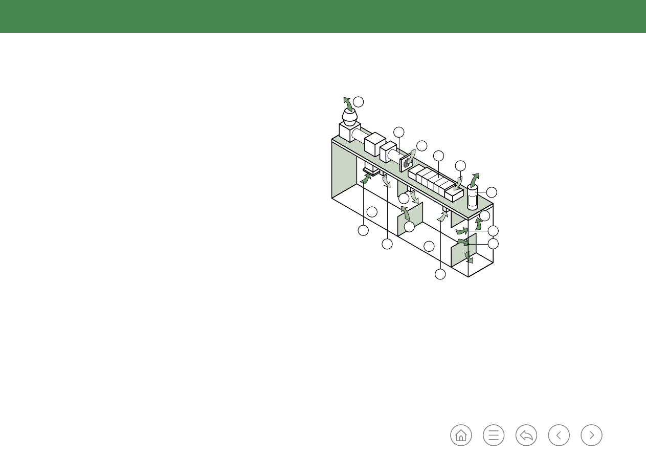
NOTE: An example of restaurant and kitchen air balancing is shown in Figure H.5.

Figure H.5 

Example of restaurant and kitchen air balancing

Key

01: Kitchen exhaust (3,000 l/s) 

02: Dedicated outdoor air  

03: Outdoor air (2,400 l/s)  

04: Roof terminal unit  

05: Outdoor air (1,000 l/s)  

06: Toilet exhaust  

07: Kitchen exhaust (3,000 l/s)  

08: Supply air (2,400 l/s)  

09: Supply air (3,300 l/s) 

10: Return air (2,300 l/s)  

11: Toilet exhaust (250 l/s)  

12: Transfer air (250 l/s)  

13: Exfiltration (150 l/s)  

14: Kitchen (negatively pressurised)  

15: Transfer air (600 l/s) 

16: Dining area (positively pressurised) 

Dubai Building Code

Part H: Indoor environment

H 33

Commercial kitchen replacement air design shall conform to Sections 6.2, 6.3  

and 7 of ASHRAE 154:2016, and to DW/172.

The make-up air shall not reduce the effectiveness of the exhaust system. Make-up 

air shall be provided by gravity or mechanical means or both. Mechanical make-up air 

systems shall be automatically controlled to start and operate simultaneously with 

the exhaust system.
The temperature differential between make-up air and the air in the conditioned 

space shall not exceed 6 ºC.

H.4.12.16  Dust, stock and refuse conveying systems 

Collectors and separators involving such systems as centrifugal separators,  

bag filter systems and similar devices, and associated supports shall be constructed 

of non-combustible materials and shall be located on the exterior of the building  

or structure. A collector or separator shall not be located within 3 m of combustible 

construction or an unprotected wall or floor opening, unless the collector is provided 

with a metal vent pipe that extends 9.1 m above the highest part of any roof.
Collectors such as “Point of Use” collectors, close extraction weld fume collectors, 

spray finishing booths, stationary grinding tables, sanding booths, and integrated 


or machine-mounted collectors may be installed indoors provided that the 

installation is in accordance with the applicable NFPA standards. These standards 

include, but are not limited to, NFPA 33, NFPA 61, NFPA 69, NFPA 70, NFPA 91, 

NFPA 499, and NFPA 654.

Collectors in independent exhaust systems handling combustible dusts may  

be installed indoors provided that such collectors are installed in compliance  

with the applicable NFPA standards mentioned above.

A delivery pipe from a cyclone collector shall not convey refuse directly into the 

firebox of a boiler, furnace, dutch oven, refuse burner, incinerator or other appliance.

An exhaust system shall discharge to the outside of the building either directly by 

flue or indirectly through the bin or vault into which the system discharges except 

where the contaminants have been removed. Exhaust system discharge may be 

recirculated provided that all of the following criteria are met: 
a) 

the solid particulate has been removed at an efficiency of not less than 99.9% 


at 10 μm (0.01 mm);

b) 

vapour concentrations are less than 25% of the lower flammable limit; and 

c)  approved equipment is used to monitor the vapour concentration. 
The outlet of an open-air exhaust terminal shall be protected with an approved metal 

or other non-combustible screen to prevent the entry of sparks.
A safety or explosion relief vent shall be provided on all systems that convey 

combustible refuse or stock of an explosive nature.

H.4.12.17  Combustion air

Solid fuel-burning appliances shall be provided with combustion air in accordance 

with the appliance manufacturer’s installation instructions. Oil-fired appliances shall 

be provided with combustion air in accordance with NFPA 31.
Combustion and dilution air for gas-fired appliances (other than fireplace stoves and 

direct-vent appliances) shall be in accordance with the requirements given in Ch. 7  

of the ASHRAE HVAC systems and equipment handbook 

[Ref. H.22]

 and in  

NFPA 54.

Dubai Building Code

Part H: Indoor environment

H 34

H.4.12.18  Chimneys and vents

H.4.12.18.1 General 

Every fuel burning appliance shall discharge the products of combustion to a vent, 

factory-built chimney or masonry chimney. The chimney or vent shall be designed for 

the type of appliance being vented.

Oil-fired appliances shall be vented in accordance with NFPA 31. Gas-fired appliances 

shall be vented in accordance with NFPA 54.
Venting systems shall be designed and constructed to develop a positive flow 

adequate to convey all combustion products to the outside atmosphere.

H.4.12.18.2 Vents

All vent systems shall be approved by the Authority. Vents shall be tested in 

accordance with UL 641.

Vent systems shall be sized, installed and terminated in accordance with the vent  

and appliance manufacturer’s installation instructions. Vents shall terminate with  

an approved cap in accordance with the vent manufacturer’s installation instructions.
Double wall vents shall terminate not less than 610 mm above the highest point of 

the roof penetration and not less than 610 mm higher than any portion of a building 

within 3,050 mm.
Venting systems of direct-vent appliances shall be installed in accordance with  

the appliance and the vent manufacturer’s instructions.

The support of all portions of vents shall be sufficient for the design and weight 


of the materials employed.
Where vents pass through insulated assemblies, an insulation shield shall be installed 

to provide clearance between the vent and the insulation material. 

H.4.12.18.3 Connectors

Connectors shall be used to connect appliances to the vertical chimney or vent, 

except where the chimney or vent is attached directly to the appliance.
Connectors shall be located entirely within the room in which the connecting 

appliance is located.

The connector shall not be smaller than the size of the flue collar supplied by the 

manufacturer of the appliance. Where the appliance has more than one flue outlet, 

and in the absence of specific instructions from the manufacturer, the connector 

area shall be not less than the combined area of the flue outlets for which it acts as a 

common connector.

H.4.12.18.4 Factory-built chimneys

Factory-built chimneys shall be approved by the Authority and shall be installed and 

terminated in accordance with the manufacturer’s installation instructions. 
Chimneys for use with open combustion chamber appliances installed in buildings 

other than dwelling units shall meet the requirements of UL 103 and shall be marked 

“Building Heating Appliance Chimney”.

H.4.12.18.5 Metal chimneys

Metal chimneys shall be constructed and installed in accordance with NFPA 211.

H.4.12.19 

Explosion control

Buildings with potential explosion hazards shall be provided with ventilation for 

explosion control as required by Ch. 10 of UAE FLSC 

[Ref. H.1]

. Explosion control 

systems shall be designed and installed in accordance with Ch. 10 of UAE FLSC 


[Ref. H.1]

Dubai Building Code

Part H: Indoor environment

H 35

H.4.13  Hydronic systems 

H.4.13.1  General

This section applies to hydronic piping systems that are part of HVAC systems. 


They include steam, hot water, chilled water, steam condensate and ground source 

heat pump loop systems.
The design and installation of hydronic systems shall meet the requirements  

of the ASHRAE Fundamentals handbook 

[Ref. H.18]

.

H.4.13.2  Materials

The pipe material and associated pipeline equipment and fittings shall have the 

appropriate temperature and pressure rating for the system in which it is operating. 

They shall be suitable for the fluid or gas conveyed.
Hydronic pipe material shall conform to the relevant ASTM standards 


(see Ch. 22 of the ASHRAE Fundamentals handbook 

[Ref. H.18]

).

H.4.13.3  Pipe joints and connections

Pipe joints and connections shall be suitable for the pressure of the hydronic system. 

H.4.13.4  Valves

Shut-off valves shall be installed in hydronic piping systems in order to enable the 

isolation of all piping equipment. 

NOTE: Further details are given in Ch.22 of the ASHRAE Fundamentals 


handbook 

[Ref. H.18]

.

H.4.13.5  Pipe installation

Pipes, valves, fittings and connections shall be installed in accordance with the 

conditions of approval.

Hydronic piping systems shall be designed and installed to permit the system to be 

drained.

Openings for pipe penetrations in walls, floors or ceilings shall be larger than the 

penetrating pipe. Openings through concrete or masonry building elements shall be 

sleeved. The annular space surrounding pipe penetrations within fire rated walls or 

floors shall be protected in accordance with Section 3, Ch. 1 of UAE FLSC 

[Ref. H.1]

.

A hydronic piping system shall not be in direct contact with building materials that 

cause the piping material to degrade or corrode, or that interfere with the operation 

of the system.
Piping shall be installed to prevent detrimental strains and stresses in the pipe. 

Provisions shall be made to protect piping from damage resulting from expansion, 

contraction and structural settlement. Piping shall be installed to avoid structural 

stresses or strains within building components.

Pipe shall be supported in accordance with Ch. 22 of the ASHRAE Fundamentals 

handbook 

[Ref. H.18]

.

The flash point of transfer fluid in a hydronic piping system shall be not less than 


28 °C above the maximum system operating temperature. The transfer fluid shall be 

compatible with the make-up water supplied to the system. 

NOTE: Further guidance is given in the ASHRAE Fundamentals handbook 

[Ref. H.18]

.

Dubai Building Code

Part H: Indoor environment

H 36

H.4.13.6  Pipe design

Hydronic piping design and sizing shall follow the guidelines within the ASHRAE 

Fundamentals handbook 

[Ref. H.18]

.

For heating and chilled water services the following design criteria shall be applied.

a)  Pressure drop shall not exceed 250 Pa/m for all pipe sizes.
b)  Maximum pipe velocity shall not exceed 1.2 m/s for pipe sizes of 50 mm and 

smaller, and 2.5 m/s for pipe sizes of 65 mm and larger.

c)  Minimum pipe velocity shall be not less than 0.45 m/s.

The above criteria shall be reviewed against the ASHRAE Fundamentals handbook 

[Ref. H.18]

 based on the particular installation and anticipated operating hours.

Piping to be embedded in concrete shall be pressure tested prior to pouring concrete.
During pouring, the pipe shall be maintained at the proposed operating pressure. 

Joints of pipe or tubing that are embedded in a portion of the building, such as 

concrete or plaster, shall meet the following requirements.
1)  Steel pipe shall be welded by electrical arc or oxygen/acetylene method.
2) 

Copper tubing shall be joined by brazing with filler metals having a melting point 

of not less than 538 °C.

3)  Polybutylene pipe and tubing shall be installed in continuous lengths or shall be 

joined by heat fusion.

H.4.13.7  Pumped hydronic systems

Hydronic cooling or heating systems shall include pressure independent two-way 

control valves. 
Expansion tanks and air separators shall be sized correctly. 
Pump motors and pump seal cooling shall be designed for a variable speed operation 

range of 15 to 50 Hz (300 rpm to 1,450 rpm). Pumps shall be selected to handle 

105% of design flow to allow for possible flow increases in the presence of low 

Delta-T condition.

The mechanical efficiency of the pump shall be not less than 85%. The electric 

efficiency of the pump motor shall be not less than 95%. 
The variable speed drive efficiency shall be not less than:

a) 

97% at 50 Hz (1,450 rpm);

b) 

95% at 35 Hz (1,000 rpm);

c) 

90% at 25 Hz (725 rpm); and

d) 

85% at 15 Hz (300 rpm).

H.4.13.8  Pressure vessels

All pressure vessels shall be in accordance with the ASME Boiler and pressure 

vessel code 

[Ref. H.23]

. They shall bear the label of an approved agency and shall be 

installed in accordance with the manufacturer’s installation instructions.

Dubai Building Code

Part H: Indoor environment

H 37

H.4.13.9  Boilers

H.4.13.9.1  General

Oil-fired boilers and their control systems shall be in accordance with UL 726. 

Electric boilers and their control systems shall be listed and labelled in accordance 

with UL 834. 

Boilers shall be designed and constructed and installed in accordance with the 

requirements of ASME CSD-1 and, as applicable, Sections I or IV of the ASME Boiler 

and pressure vessel code 

[Ref. H.23]

, or NFPA 85.

Boilers shall be installed in accordance with the manufacturer’s instructions. 

Operating instructions shall be permanently attached to the boiler, to avoid 

misplacement. Boilers shall have all controls set, adjusted and tested by the installer. 

The manufacturer’s rating data and the nameplate shall be attached to the boiler.

Boilers shall be mounted on floors of non-combustible construction.
Hot water and steam boilers shall have all operating and safety controls set and 

operationally tested by the installing Contractor. A complete control diagram and 

boiler operating instructions shall be provided by the installer for each installation.

H.4.13.9.2  Boiler connections

Every boiler or modular boiler shall have a shut-off valve in the supply and return 

piping. For multiple boiler or multiple modular boiler installations, each boiler or 

modular boiler shall have individual shut-off valves in the supply and return piping.

H.4.13.9.3  Safety and pressure relief valves and controls 

All steam boilers shall be protected with a safety valve. Hot water boilers shall be 

protected with a safety relief valve.
All pressure vessels shall be protected with a pressure relief valve or pressure-limiting 

device as required by the manufacturer’s installation instructions for the pressure 

vessel.
Safety and safety relief valves shall be approved by the Authority and shall have a 

minimum rated capacity for the equipment or appliances served. Safety and safety 

relief valves shall be set at a maximum of the nameplate pressure rating of the boiler 

or pressure vessel.

H.4.13.9.4  Boiler low-water cut-off

All steam and hot water boilers shall be protected with a low-water cut-off control.
The low-water cut-off shall automatically stop the combustion operation of the 

appliance when the water drops below the lowest safe water level as established by 

the manufacturer.

H.4.13.9.5  Steam boiler blow-off

Every steam boiler shall be equipped with a quick-opening blow-off valve. The valve 

shall be installed in the opening provided on the boiler. 

The size of the valve shall be either as specified by the boiler manufacturer or 

determined by the size of the valve opening.

H.4.13.9.6  Hot water boiler expansion tank

An expansion tank shall be installed in every hot water system. For multiple boiler 

installations, at least one expansion tank shall be provided. Expansion tanks shall 

be of the closed or open type. Tanks shall be rated for the pressure of the hot water 

system.

Dubai Building Code

Part H: Indoor environment

H 38

H.4.13.9.7  Gauges

Every hot water boiler shall have a pressure gauge and a temperature gauge, or 

a combination pressure and temperature gauge. The gauges shall indicate the 

temperature and pressure within the normal range of the system’s operation.

H.4.13.9.8  Testing

Hydronic piping systems, other than ground source heat pump loop systems, shall be 

tested hydrostatically at one and half times the maximum system design pressure, 

but not less than 689 kPa (100 psi). The duration of each test shall be not less than 

15 min. 
Ground source heat pump loop systems shall be tested before connection (header) 

trenches are backfilled. The assembled loop system shall be pressure tested with 

water at 689 kPa (100 psi) for 30 min with no observed leaks. Flow and pressure 

loss testing shall be performed, and the actual flow rates and pressure drops shall 

be compared to the calculated design values. If actual flowrate or pressure drop 

values differ from calculated design values by more than 10%, the problem shall be 

identified and corrected. 

Upon completion of the assembly and installation of boilers and pressure vessels, 

acceptance tests shall be conducted in accordance with the ASME Boiler and 

pressure vessel code 

[Ref. H.23]

H.4.13.9.9  Flushing, cleaning and water treatment

Before the system is operated, all water piping shall be flushed, chemically cleaned 

and treated following the guidelines in the ASHRAE HVAC applications handbook 

[Ref. H.17]

.

H.4.13.10  Refrigeration

H.4.13.10.1 General 

The design, construction and installation of refrigeration systems shall meet the 

requirements of the ASHRAE Refrigeration handbook 

[Ref. H.24]

 and ASHRAE 15, 

including:
a)  system requirements;
b) 

refrigerant types and classifications;

c)  system application requirements;
d)  machinery room requirements;
e)  refrigerant piping installation and materials; and
f)  testing.

H.4.13.10.2 Refrigerant and ozone depletion management 

Refrigerants with zero ozone depletion potential or with global warming potential 

less than 100 shall be used, unless the equipment contains less than 0.23 kg of 

refrigerant. 

Dubai Building Code

Part H: Indoor environment

H 39

H.4.14  HVAC systems controls and metering

H.4.14.1  Controls for HVAC systems 

HVAC systems shall be equipped with efficient controls to reduce energy 

consumption, in accordance with ASHRAE 90.1. 

Control systems shall meet the following requirements.
a)  Control systems shall be divided into sub-zones with independent controls for 

each building zones. Controls for each sub-zone may vary based on the zone’s 

exposure to sun or cooling load levels or by nature of usage. 

b)  All independent control areas shall be able to: 

1)  control temperature; and
2)  turn off the systems when the building or the controlled part of the building is 

not occupied. 

c)  Central systems shall operate only when required by zonal control systems. 

H.4.14.2 

Building management system (BMS)

Buildings having a cooling load of 1,000 kW, or a gross area of 5,000 m

2

 or greater, 

shall have a BMS capable of ensuring that the building’s systems operate as designed 

and as required during all operating conditions. The system shall provide full control 

and monitoring of system operations, apart from diagnostic reporting. 

The system shall control the chiller plant and HVAC equipment as a minimum, 

and record energy and water consumption. It shall also monitor and record the 

performance of these items. 

BMS systems shall be configured to optimize energy usage.

H.4.14.3  H.4.14.3 Control systems for hotel rooms 

Hotel guest rooms shall incorporate automatic control systems that can turn off the 

lighting, air-conditioning and power when the room is not occupied. 
Each guest room should also incorporate an automatic control system that can turn 

off the air-conditioning when a balcony door or window is kept open. 
Outdoor air ventilation shall be provided so that rooms can be kept well-ventilated 

and under positive pressure during unoccupied periods. The ventilation shall be 

demand-controlled and capable of being activated by occupancy sensor or light 

switch. It shall be electrically interlocked.

H.4.14.4  Air-conditioning metering 

In buildings supplied by a central air-conditioning source (such as a chiller plant 

or district cooling), or where cooling energy is delivered individually to several 

consumers, smart meters approved by the Authority shall be installed to measure 

and record chilled water supply to air-conditioning units. The meters shall provide 

accurate records of consumption, which shall be determined as follows.
a)  Smart energy meters designed to measure the supply of chilled water shall be 

installed for each dwelling unit, office or tenant. The measuring device shall 

measure the water flow and supply and return temperatures to determine the 

temperature differential for calculating the amount of cooling energy consumed.

b)  Where a BMS is installed, the smart metering shall be connected to allow real 

time profiling and management of energy consumption.

c) 

Smart meters used shall be specifically designed for the measurement of chilled 

water and not for hot water.

d)  All smart meters shall be capable of remote data access and shall have data 

logging capability.

e)  Virtual meters using run-hours are not acceptable as sub-meters.
The meter readings and actual consumption details shall only be for energy 

measurement, demand management and cost allocation purposes. 

Dubai Building Code

Part H: Indoor environment

H 40

H.4.15  Fuel oil piping and storage

H.4.15.1  General 

The design and installation of fuel oil piping systems, and the storage of fuel oil, shall 

be in accordance with Ch. 13 of UAE FLSC 

[Ref. H.1]

, Ch. 22 of the  

ASHRAE Fundamentals handbook 

[Ref. H.18]

, and NFPA 31.

H.4.15.2  Materials

Piping materials shall conform to the following standards:
a)  brass pipe: ASTM B43;
b)  brass tubing: ASTM B135;
c)  copper or copper-alloy pipe: ASTM B42, ASTM B302;
d) 

copper or copper-alloy tubing: (type K, L or M) ASTM B75, ASTM B88, 


ASTM B280;

e)  non-metallic pipe: ASTM D2996;
f)  steel pipe: ASTM A53, ASTM A106; and
g)  steel tubing: ASTM A254, ASTM A539.
Piping materials shall be rated for the operating temperatures and pressures of the 

system. They shall be compatible with the type of liquid to be conveyed in the pipes.

H.4.15.3  Joints and connections

Joints and connections shall be of a type approved for fuel oil piping systems.
Allowance shall be made for expansion, contraction, jarring and vibration. Piping 

other than tubing, connected to underground tanks, except straight fill lines and test 

wells, shall be provided with flexible connectors, or otherwise arranged to permit the 

tanks to settle without impairing the tightness of the piping connections.

H.4.15.4  Piping support

Pipe hangers and supports shall have sufficient strength to withstand all anticipated 

static and specified dynamic loading conditions associated with the intended use. 

Pipe hangers and supports that are in direct contact with piping shall be of approved 

materials that are compatible with the piping and that will not promote galvanic 

action.

Hangers and anchors shall be attached to the building construction in an approved 

manner. The spacing between piping supports shall be not less than the minimum 

specified in ANSI MSS SP-69.

Dubai Building Code

Part H: Indoor environment

H 41

H.4.16 

Specific appliances and equipment

H.4.16.1 

Gas-fired appliances

Gas-fired appliances shall be approved, designed, installed and constructed in 

accordance with NFPA 54 and Ch.11 in UAE FLSC 

[Ref. H.1]

.

H.4.16.2  Fireplace stoves and room heaters

Stoves and solid fuel-type room heaters shall be approved by the Authority. They 

shall be installed in accordance with the manufacturer’s installation instructions. 

Fireplace stoves shall be tested in accordance with UL 737. Solid fuel-type room 

heaters shall be tested in accordance with UL 1482. 
Fireplace inserts shall be approved by the Authority in accordance with 


UL 1482. They shall be installed in accordance with the manufacturer’s installation 

instructions.

H.4.16.3 

Cooling towers, evaporative condensers and fluid coolers

A cooling tower used in conjunction with an air-conditioning appliance shall be 

installed in accordance with the manufacturer’s installation instructions and the 

requirements given in Ch. 40 of the ASHRAE HVAC systems and equipment 

handbook 

[Ref. H.22]

.

Cooling towers, evaporative condensers and fluid coolers shall be located such as to 

prevent the discharge vapour plumes from entering occupied spaces. They shall be 

readily accessible for maintenance and repair. Plume discharges shall be not less than 

1.5 m above or 6.1 m away from any ventilation inlet to a building.

The separation distance between cooling tower exhaust and external ventilation air 

intakes or other building openings shall be in accordance with ASHRAE 62.1:2019. 

The minimum separation distance shall be calculated based on the wind direction and 

the location of outdoor air intake as described in Clause 5.5.1(b) and Appendix B: 

B1.2, B1.3 and B2.2 of ASHRAE 62.1:2019.

Cooling towers shall be selected to achieve the minimum energy performance 

requirements given in ASHRAE 90.1. All cooling towers shall be Cooling Technology 

Institute certified and shall be selected at 32.0 °C wet-bulb temperature and cooling 

tower approach between 2 °C to 3 °C.

H.4.16.4  Infrared radiant heaters

Infrared radiant heaters shall be fixed in a position that is free of fuel and electric 

supply lines. Heaters shall be installed with clearances from combustible material in 

accordance with the manufacturer’s installation instructions and the  

ASHRAE Fundamentals handbook 

[Ref. H.18]

.

H.4.16.5  Sauna heaters

Sauna heaters shall be installed in accordance with UL 875 and the manufacturer’s 

installation instructions.

H.4.16.6  Engine and gas turbine-powered equipment and appliances

The installation of liquid-fuelled stationary internal combustion engines and gas 

turbines, including exhaust, fuel storage and piping, shall meet the requirements of 

NFPA 37. Stationary engine generator assemblies shall meet the requirements of 


UL 2200.

Permanently installed equipment and appliances powered by internal combustion 

engines and turbines shall be installed in accordance with the manufacturer’s 

installation instructions and NFPA 37. 

Dubai Building Code

Part H: Indoor environment

H 42

H.4.16.7  Pool and spa heaters

Pool and spa heaters shall be installed in accordance with the manufacturer’s 

installation instructions.

Oil-fired pool and spa heaters shall be tested in accordance with UL 726. Electric pool 

and spa heaters shall be tested in accordance with UL 1261.

H.4.16.8  Cooking appliances

Cooking appliances that are designed for permanent installation (including ranges, 

ovens, stoves, broilers, grills, fryers, griddles and barbecues) shall be approved by the 

Authority and relevant UL Code, and installed in accordance with the manufacturer’s 

installation instructions. 

NOTE: Further guidance is given in the ASHRAE Fundamentals handbook 

[Ref. H.18]

.

H.4.16.9  Conversion burners

The installation of conversion burners shall conform to ANSI Z21.8.

H.4.16.10  Unit heaters

Unit heaters shall be installed in accordance with the listing and the manufacturer’s 

installation instructions. Oil-fired unit heaters shall be tested in accordance with 


UL 731.

Suspended-type unit heaters shall be supported by elements that are designed and 

constructed to accommodate the weight and dynamic loads. Hangers and brackets 

shall be of non-combustible material. Suspended-type oil-fired unit heaters shall be 

installed in accordance with NFPA 31. 

H.4.16.11  Stationary fuel cell power systems

Stationary fuel cell power systems having a power output not exceeding 10 MW shall 

be tested in accordance with ANSI/CSA FC 1 and installed in accordance with the 

manufacturer’s installation instructions and NFPA 853.

Central battery systems for emergency lighting shall also conform to Ch. 6 of the 

UAE FLSC 

[Ref. H.1]

.

H.4.16.12  Gaseous hydrogen systems

The installation of gaseous hydrogen systems shall be in accordance with the 

applicable requirements of NFPA 2. 

H.4.16.13  Radiant heating systems

Electric radiant heating systems selection shall be approved by the Authority 

and shall be installed in accordance with the manufacturer’s instructions and the 

ASHRAE Fundamentals handbook 

[Ref. H.18]

.

Clearances for radiant heating panels to any wiring, outlet boxes and junction boxes 

used for installing electrical devices or mounting luminaires shall be in accordance 

with NFPA 70. 

H.4.16.14  Evaporative cooling equipment

Evaporative cooling equipment shall be installed in accordance with the 

manufacturer’s instructions and the ASHRAE Fundamentals handbook

 [Ref. H.18]

H.4.16.15  High volume large diameter fans

High volume large diameter fan selection shall meet the requirements of the 

ASHRAE Fundamentals handbook 

[Ref. H.18]

. The fans shall be tested in accordance 

with ANSI/AMCA 230, labelled in accordance with UL 507 and installed in 

accordance with the manufacturer’s instructions.
 

Dubai Building Code

Part H: Indoor environment

H 43

H.5 

Water supplies

H.5.1 

General

This section covers all occupancies except healthcare and low-rise residential 

dwellings (see 

Part K

).

The requirements for healthcare buildings, and all relevant codes and standards, are 

identified in the DHA Regulations 

[Ref. H.2 to Ref. H.11]

 and DHA Health facility 

guidelines 

[Ref. H.12 to Ref. H.16]

.

This section sets out the minimum requirements and basis of design for the water 

services systems within a building. It also includes minimum sustainability criteria.

For systems or applications not covered by this section, the requirements and 

recommendations in the following documents shall be met: 
a)  BS EN 806;
b)  BS EN 8558;
c) 

HSE Approved Code of Practice L8 

[Ref. H.25]

 and associated technical guidance 

documents 

[Ref. H.26 to Ref. H.28]

d) 

HSG272 

[Ref. H.29]

 and HSG220 

[Ref. H.30]

; and

e) 

Water Supply (Water Fittings) Regulations 

[Ref. H.31]

H.5.2 

Water conservation and reuse 

H.5.2.1 

Compliance methods 

There are two compliance routes for water use. 
a) 

Elemental method: All buildings shall conform to H.5.2.2. 

b)  Performance method: A calculation method may be employed for a building which 

might not meet the elemental requirements for water-efficient fixtures detailed in 

H.5.2.2. 

The performance method shall use supporting calculations to compare the annual 

water consumption of the proposed building with that of a reference building which 

meets the elemental requirements of H.5.2.2. The reference building shall be equal in 

shape, size and operational patterns to the proposed building. 
Compliance will be demonstrated if the calculated annual water consumption of the 

proposed building is equal to or lower than the annual water consumption of the 

reference building. 

H.5.2.2 

Water-efficient fittings 

The following water-efficient fittings shall be used: 

a) 

fixtures with a flow rate less than or equal to the flow rates shown in Table H.5;

b) 

dual flush toilets;

c)  automatic (proximity detection) or push-button faucets in all public facilities; 
d)  cisterns serving single or multiple urinals in public, commercial and industrial 

buildings with manual or automatic flush controls that operate based on usage 

patterns. Only sanitary flushing shall be possible in the event of building closure 

or shutdown (including overnight). 

Faucets installed for specialized application may be exempted from meeting the flow 

rates, subject to Authority approval.

Dubai Building Code

Part H: Indoor environment

H 44

H.5.2.5 

Water-efficient irrigation 

Exterior landscaping (including green roofs) shall be irrigated using non-potable 

water (see H.5.4.6 for irrigation system examples), or by drip or subsoil water delivery 

systems. 

All irrigation systems shall incorporate backflow prevention devices if they are 

connected to a potable water source in any location. The backflow prevention devices 

shall be installed in line with the manufacturer’s requirements. 

H.5.2.6 

Water metering

H.5.2.6.1  Main meters

Dubai Electricity and Water Authority (DEWA) main meters shall be installed to 

measure and record the water demand and consumption of a building in accordance 

with 

G.9

.

H.5.2.6.2  Sub-meters

Each individual tenancy in a building shall have a DEWA sub-meter installed which is 

connected to a building main meter.
Sub-meters shall also be installed to record consumption data for internal and 

external (e.g. irrigation) water uses, for buildings having:
a)  a cooling load of 1 MW or greater; and/or
b)  a gross area of 5,000 m

2

 or greater.

Where a BMS is installed, metering shall be integrated into the system to allow real-

time profiling and management of water demand and consumption.

Virtual meters using run-hours shall not be used as sub-meters.
The sub-meters should be used for demand management and cost allocation 

purposes.

Fixture type  

Maximum flow rate

Showerheads

8 l/min

Hand washbasins

6 l/min

Kitchen sinks

7 l/min

Dual flush toilets

6 l full flush
3 l part flush

Urinal

2.4 l in non-public facilities 

1 l per flush or waterless in public facilities 

Table H.5  Maximum flow rate 

H.5.2.3 

Condensate drainage 

Condensate water produced by air-conditioning equipment shall be collected and 

disposed of appropriately. Condensate collection pans and drainage pipes shall be 

installed to provide proper drainage and to prevent any stagnant water. An air break 

of not less than 25 mm shall be provided between the condensate piping and the 

wastewater pipe. If the condensate water is not reused, it shall be discharged into the 

wastewater system through a properly sized water trap. 

H.5.2.4 

Condensate reuse 

Where the cooling load is greater than 350 kW, condensate water shall be recovered 

and reused from all of the following:
a)  air-conditioning equipment;
b)  air handling units; and
c)  equipment handling a mixture of return air and outside air, where the outside air 

is not preconditioned.

NOTE: The condensate water can be reused for irrigation, toilet flushing, or other 


on-site purposes where it will not come into direct contact with the human body.  

The condensate water can also be reused for heat recovery (see H.4.8.2).

Dubai Building Code

Part H: Indoor environment

H 45

H.5.2.7 

Wastewater reuse 

If a system is installed for the collection and reuse of greywater produced within the 

building, or for the use of treated sewage effluent (TSE) from an external source, the 

following requirements shall be met. 
a)  The building shall be dual-plumbed for the collection and recycled use of 

greywater. Any pipes which transport greywater shall be colour-coded differently 

from pipes that are used for potable water and be labelled “Not suitable for 

drinking”. 

b)  There shall be an air break of not less than 25 mm between any potable water 

sources and greywater collection systems. 

c)  Greywater shall not be used for purposes where it will come into direct contact 

with the human body. It shall be treated to the standard required by the 

Authority. 

Commercial car washing facilities shall recover and reuse at least 50% of their 

wastewater.
All wastewater reuse systems shall incorporate sampling points to enable water 

quality testing to be undertaken. 

H.5.2.8 

Cooling tower water supply 

Potable water supplied by DEWA shall not be used for heat rejection purposes. 

Where cooling towers are used, treated sewage effluent (TSE), seawater or recycled 

water shall be used to meet the water demand for all heat rejection purposes. 

Secondary water sources shall be approved by DEWA. 

A separate totalising meter shall be fitted on the water supply line to the individual 

cooling towers. A daily log of water use shall also be kept. 
Water treatment plant will be required to remove impurities from the cooling tower 

feed water and the circulatory water. Leaving cooling tower water untreated can lead 

to organic growth, fouling, and corrosion of the system. This reduces the efficiency 

and service life of the cooling tower plant. 
The type of water treatment system required depends on a number of  

factors including:
a)  type of cooling tower;
b)  quality of water feed required;
c)  cooling tower manufacturer’s requirements;
d)  chemistry of make-up and circulation water;
e)  whether or not blowdown will be treated for reuse in the cooling tower; and
f)  type of heat exchanger.

Typically, water treatment systems shall include filtration and ultrafiltration, ion 

exchange/softening, chemical addition of inhibitors and biocides and an automated 

monitoring system. The water treatment system shall regulate and control the levels 

of alkalinity, chlorides, hardness, iron levels, organic matter, silica, sulphates, total 

dissolved solids and total suspended solids in the system. 

Dubai Building Code

Part H: Indoor environment

H 46

The cooling water system shall not contain dead legs or sections where debris  

and biofilms might accumulate.
The cooling tower shall be fitted with drift eliminators to minimize the release 


of water droplets.
The cooling water system should be easily and safely accessible for cleaning, 

maintenance and disinfecting. 
The operation and maintenance of water systems serving a cooling tower shall be 

designed in accordance with HSE Approved Code of Practice L8 

[Ref. H.25]

H.5.3 

Sustainable water heating system

Central or decentralized hot water systems shall be configured utilizing a sustainable 

hot water heating technology, such as solar hot water, except in buildings where: 
a)  such a hot water system would be impractical due to tenancy, metering, and 

pipework distribution constraints; or 

b)  hot water generation utilizing local point-of-use electric water heaters would 

provide a more energy-efficient design solution.

The percentage heating contribution from the solar hot water heating system 

depends on the occupancy and estimated hot water usage profile. The system 

designer shall target 75% of the total hot water daily demand being produced by 

the solar hot water system. To reduce system standing losses, all hot water storage 

vessels and distribution pipework shall be insulated.

H.5.4 

Cold water services 

H.5.4.1 

Cold water distribution

Cold water shall be supplied to the following sanitary fittings: 

a) 

Water closet flushing;

b)  washbasins;
c)  sinks;
d)  showers;
e)  maintenance areas, workshops and back of house areas;
f)  cleaners’ sinks; and
g)  bib tap points.
Where municipal water system pressures are inadequate to serve the building, a 

pumped water supply system shall be provided to deliver water to sanitary fittings at 

all building levels. 
The booster pump set shall be connected to a water storage tank. The booster set 

shall provide a pressurized supply of cold water to all cold water outlets and hot 

water plants.
The booster pumps should be multistage, variable speed pumps rather than a duty/

standby single pump system. This approach provides a longer system life with higher 

energy efficiencies, as well as providing a wider range of system flow rates for the 

facility.

NOTE: Depending on the occupancy type and resiliency strategy required, the 

booster pumps might need to be connected to the building emergency power supply.

The pumped cold water distribution strategy shall be determined by the height of the 

building. For high-rise buildings, intermediate water plant rooms might be required at 

certain floor levels to provide a system pressure break.

Dubai Building Code

Part H: Indoor environment

H 47

Cold water systems should be maintained, where possible, at a temperature below  

20 °C. The water should reach a temperature of no more than 20 °C within 2 min  

at the outlets.
All booster pumps shall have an accumulator vessel and incorporate automatic 

controls to ensure even pump wear and prevent system stagnation.

For all buildings, water meter rooms, water meter and isolation valve locations shall 

conform to DEWA Regulations 

[Ref. H.32]

.

Water check meters shall be installed on all water services connections to mechanical 

plant to monitor water consumption. 
All parts of the cold-water system, including storage tanks and pipework, shall be 

designed to avoid water stagnation and ensuring flow through all parts of the system. 

Dead legs in the cold-water systems shall be avoided.
The cold water distribution system shall be designed in accordance with the relevant 

parts of the Water Supply (Water Fittings) Regulations 

[Ref. H.31]

, BS EN 806 and 

BS EN 8558.

H.5.4.2 

Cooled water systems

In buildings where there is a requirement for a cooled water supply (15 °C to 20 °C), 

this can be achieved via the installation of a heat exchanger connected to the building 

chilled water system. The heat exchanger is connected to the final cooled water 

storage tank that serves this system. Cooled water can be utilized to serve wash hand 

basins, sinks, baths, showers and shatafs. Cooled water systems (see Figure H.6) are 

often required in healthcare buildings, hotels and sports facilities. In buildings where 

a chilled water system is not available, a cooled water system could be achieved by 

connection to heat pump.

Cooled water systems shall be served from a separate dedicated system including 

water tanks, pumps, water treatment and pipework distribution system. All system 

components shall be clearly labelled to prevent the risk of cross connection to other 

building water distribution systems. 

NOTE: Water that does not require cooling needs greater maintenance for the 

purposes of water quality and Legionella protection. 

Figure H.6 

Cooled water system schematic arrangement

Key

01: Cold water storage tank 

02: Cold water supply 

03: Plate heat exchanger 

04: To domestic cold water 

services

01

04

03

02

Dubai Building Code

Part H: Indoor environment

H 48

04

02

05

01

08

13

12

02

11

07

10

09

03

06

Key

01: Aerated shower head 

02: Spray taps  

03: Waterless/air flush urinal  

04: Greywater controls 

05: Low volume cistern 

06: Dual flush toilet 

07: Low water appliances 

08: Rainwater treatment  

09: Rainwater storage  

10: Rainwater harvesting controls 

11: Water meter 

12: Greywater treatment 

13: Greywater storage tank 

H.5.4.3 

Water recycling systems

Water recycling systems installed for the flushing of water closets or landscape 

irrigation (see Figure H.7) shall be served from separate dedicated plant that 

includes water tanks, pumps, water treatment and associated pipework distribution 

system. All system components shall be clearly labelled to prevent the risk of cross 

connection to other building water distribution systems. 

Figure H.7 

Water recycling

H.5.4.4 

Laboratory buildings

The cold water supply to laboratory appliances and laboratory hot water plant shall 

be served from separate dedicated plant that includes water tanks, pumps, water 

treatment and associated pipework distribution system. All system components shall 

be clearly labelled to prevent the risk of cross-connection to other building water 

distribution systems. 

H.5.4.5 

Swimming pool cold water supply

A cold water supply shall be provided to serve the pool filtration and chemical water 

treatment plant of a swimming pool. 
The cold water supply that serves the pool water treatment system shall be fed from 

a dedicated cold water break tank to isolate the chemical treatment plant completely 

from the building’s cold water supply. A booster pump set shall be connected to 

the break tank to provide a pressurized supply of cold water to the water treatment 

equipment.

The cold water break tank and booster pump set shall be located in the pool filtration 

plant room. The pool filtration shall be designed by the pool filtration specialist. 

NOTE: The objective of the pool water treatment system is to provide a hygienic, 

safe, comfortable and pleasant environment both for the bathers and spectators in 

the pool hall. This is to be achieved under anticipated bathing load levels.

Dubai Building Code

Part H: Indoor environment

H 49

H.5.4.6 

Irrigation water supply

When a supply of water for the irrigation of lawned, planted areas and green roofs is 

required, the system shall be supplied from a recycled water system. Suitable recycled 

water systems include:
a)  greywater recycling systems; and
b)  condensate reuse systems.
Water disinfection shall be provided for above-ground sprinkler irrigation systems 

that create an aerosol of water droplets. 

NOTE 1: Disinfection of the water supply is not required for subsurface landscape 

irrigation systems.

NOTE 2: Dispersal disinfection filtration systems provide an effective means of 

treatment for water irrigation systems. 

The irrigation system shall be served from the water recycling plant or via a separate 

dedicated plant that includes a storage tank, pumps, filtration and water treatment 

plant. A backflow protection device shall be provided at point of connection to each 

irrigation supply. 
The irrigation water supply shall be fed from a dedicated pipework distribution 

system. Isolation and drain valves shall be provided to enable the system to be easily 

maintained.
All system irrigation system components shall be clearly labelled to prevent the risk 

of cross-connection to other building water distribution systems.

Dubai Building Code

Part H: Indoor environment

H 50

Figure H.8 

Alternative cold water supply system arrangements

Key

01: Cold water storage tank 

02: Cold water booster pump set

01

01

01

02

01

02

01

02

02

01

H.5.5 

Potable water storage tanks 

H.5.5.1 

General

Potable water storage shall be provided in the building, to protect the building 

against interruptions to the incoming mains supplies and to enable water supply 

pressures to be safely maintained.

H.5.5.2 

Water tank locations

NOTE: It is common in Dubai for buildings to incorporate two potable water storage 

tanks (not including fire suppression water storage), with one tank located at the 

incoming main (basement or ground floor) and one tank at roof level. This strategy 

is permitted, but the popularity of pressure boosting systems has enabled cold 

water storage at roof level to be omitted (see Figure H.8). The location of cold-water 

storage tanks is also influenced by the height of the building. For high-rise buildings, 

intermediate water plant rooms might be required to provide a system pressure 

break.

A risk assessment shall be carried out to determine the best location for the potable 

water tanks. The assessment shall take into account building spatial constraints, and 

access and maintenance. If there is a risk of flooding, the potable water tanks shall 

not be placed in areas of flooding risk such as the basement or at ground floor level.

Water tanks shall be positioned as far as possible from drainage network lines, 

manholes, septic tanks and cesspits. In all cases, drainage pipelines shall not run 

above or next to above- or below-ground water tanks.
DEWA shall have access to any part of the building to conduct an inspection of the 

water supply tanks, to verify compliance with public health conditions and associated 

technical specifications. 

Dubai Building Code

Part H: Indoor environment

H 51

User category

Consumption rates (l/cap./day)

Day clinic (per medical practitioner) including visitors

300 - 450

Club house/recreation

100

Commercial buildings

60-100

Entertainment & leisure/theater

10-60

Events

10-50

Guardhouse

60-75

Headquarters

60-80

Hotels (per employee)

60-80

Hotels (per guest)

200-300

Laboratory

60-80

Labour accommodation

80-150

Local plaza/retail/town center

60-82

Logistic, academic & business center

60-75

Manufacturing/mineral

60-80

Medical (per bed)

350-450

Table H.6 

DEWA reference per capita consumption rates

H.5.5.3 

Water storage tank sizing

The capacity of domestic water supply tanks shall be calculated based on the actual 

demand of the building occupants. As a minimum, water tanks shall be sized based 

on 24 h demand from all water connections except firefighting, and shall be not less 

than 1 m

3

. Water tanks for labour accommodation shall be sized for 48 h demand. 

Table H.6 gives water consumption rates in accordance with DEWA transmission 

planning guidelines 

[Ref. H.36]

. The maximum water consumption rates in each 

range should not be used unless justified based on project requirements.

User category

Consumption rates (l/cap./day)

Mixed used commercial

60-80

Mixed used residential

250-350

Mosques

10 - 60

Nursery/child care centre

50-70

Offices

45-60

Public amenities

10 - 50

Residential buildings (flat)

200-300

Restaurant (per meal)

10-15 l/d per meal

Schools/university

40-60

Shops

45-60

Theatre

10-50

Villas

250-350

Visitors

14-40

Industrial (workshops/machinery/warehouse, etc.)

60-80

Dubai Building Code

Part H: Indoor environment

H 52

H.5.5.4 

Water tank construction

Domestic water tanks shall be manufactured from a material that does not rust or 

corrode. The tank material shall not: 
a)  adversely affect the nature (e.g. colour, taste or odour) or chemical properties  

of the water;

b)  be affected by either temperature or humidity;
c)  be impervious to light; or 
d)  cause any harmful effect to human health.
The tank shall be free from sharp corners that could accumulate dirt, microbes  

or prevent effective periodic cleaning.
The maximum height of reinforced concrete tanks shall be calculated by a  

Structural Engineer.
The height of pre-insulated glass-reinforced plastic (GRP) tanks shall not exceed 

more than 3 m, with water levels not exceeding 2.5 m and free board not less than 

0.5 m.
Cold water storage tanks shall be arranged in one of the following two ways:
1) 

divided into two equal compartments (50/50 configuration as shown in 


Figure H.9). This type of arrangement allows for one part of the tank to be 

cleaned, disinfected, serviced, repaired, inspected, etc. while the other is in 

operation. This means that a water supply pipe needs to be supplied to each 

part of the tank, as set out in local requirements. To ensure that the water flow 

is provided when required, and that each tank section is provided with an equal 

volume of flow, a water meter shall be installed on the supply to each ball float 

or chain valve; or

2) 

provided as two separate tanks that are installed in a parallel configuration. 

For both arrangements, the connecting pipework and valves shall achieve a balanced 

throughput of water through each tank or tank section, avoiding deadlegs that can 

lead to water stagnation.
Domestic water supply tanks shall be provided with lockable manholes. The 

dimensions of the manhole openings shall be sufficient to allow a person to access 

the tank safely for cleaning. Openings shall be located away from public circulation 

areas and sources of contamination.

Figure H.9 

Sectional cold water storage tank arrangement

Dubai Building Code

Part H: Indoor environment

H 53

In each water tank (or water tank section when divided tanks are used), the following 

components shall be provided:
i)  an isolation valve at the inlet and outlet of the tank division;
ii)  a valve strainer at the outlet of each tank division;
iii)  drain connection at the bottom of each tank. The invert of the drain shall  

be located to fully drain that division of the tank;

iv) 

overflow pipe from each division of the tank;

v) 

overflow warning pipe with insect protection screen of 0.65 mm mesh. 


The screen area shall be capable of passing the same amount of water  

as the overflow or warning pipe;

vi)  an external and internal access ladder; and
vii)  a vent pipe with a corrosion resistant air inlet mesh.

In circumstances where it might be difficult to install an overflow or a warning pipe 

to a drain line, an audible warning alarm shall be installed to inform the building 

maintenance team of a tank overflow occurrence.

Water tanks that are installed above ground shall be constructed from pre-insulated 

GRP. Tanks shall be installed in a conditioned space that is free from contamination 

and shall not be exposed to the external Dubai climate. 

Sectional GRP tanks shall be specified with externally flanged connections (base and 

sides) to simplify tank cleaning and sterilization.
There shall be a 1 m free space around all sides and above the top of the GRP tank 

for equipment maintenance. 
Raw water tanks can be constructed out of concrete and can be buried below ground, 

or they can be located within a conditioned room. All concrete tanks shall be lined 

with a suitable GRP coating or liner.

Tanks shall be cleaned and sterilized after completion of work and prior to the actual 

use of the tank. All cold water storage tanks shall incorporate a laboratory testing 

certificate stating its suitability for storing drinking water in accordance with DEWA 

requirements 

[Ref. H.32]

H.5.5.5 

Tank pump room 

The pump room shall be of sufficient size to enable operation, maintenance and 

repair of the various pumps that connect to the tank. Each pump set shall be installed 

on a reinforced concrete base.

H.5.5.6 

Firefighting water tanks

The firefighting water tank and pump connection arrangements shall conform to 


Ch. 9 of UAE FLSC 

[Ref. H.1]

Firefighting water tanks shall be located next to or below the fire pump room, 

depending upon the pump type selected. They shall conform to Table 1.9, Ch. 1 of 

UAE FLSC 

[Ref. H.1]

The firefighting water tank area shall have adequate drainage, and an arrangement 

such that an overfilling tank does not flood the area and the pump room, in 

accordance with Table 9.3, Ch. 9. of UAE FLSC 

[Ref. H.1]

. The pump room and floor 

corridors shall be provided with a drainage facility to drain the dripped and leaked 

water or water flooded during firefighting operations. 
A centralized firefighting water tank to serve multiple buildings in a development is 

permitted provided that the buildings are owned by one entity and the maintenance 

of the system is managed and controlled as part of the common area. The size of the 

tank shall be designed for more than one fire event simultaneously, to be agreed 


with DCD.

A mechanical floor shall be provided every 90 m in super high-rise buildings to 

accommodate the firefighting pumps and tanks required by Section 4.2, Ch. 9 of 


UAE FLSC 

[Ref. H.1]

.

Dubai Building Code

Part H: Indoor environment

H 54

H.5.5.7 

Combined firefighting and water storage

Where water tanks are also used for firefighting purposes, the water storage capacity 

shall be increased to include firefighting water storage capacity and the system shall 

be designed to facilitate regular turnover of the cold water storage volume in the 

tank. 
The tank and pump connection arrangements shall conform to Ch. 9 of  

UAE FLSC 

[Ref. H.1]

The fire pump test line shall not discharge back into the tank.

H.5.6 

Water treatment

H.5.6.1 

Treatment against microbiological bacteria growth

A proper and effective method shall be implemented to control microbiological 

bacteria growth in building water systems, cooling towers, and internal and external 

water features. 
One of the following control methods shall be used:
a)  pasteurization; 
b)  chemical treatment (biocides, chlorine, etc);
c)  silver copper ionization;
d) 

filtration systems.  

The choice depends on the building, the water systems it serves, the source of the 

incoming water supply, and the capital and on-going maintenance costs.
The designer shall formulate a strategy to maintain water quality and minimize the 

risk of Legionella bacteria for each manufactured water system from the point of 

supply to point of use. The suitability of the materials used in the construction of the 

manufactured water system shall not adversely affect water quality.

Water systems shall not use materials that aid microbial growth.
Any cooling water system, including its make-up water tanks, shall be provided with a 

suitable automatically controlled water treatment system (e.g. an automatic biocide-

dosing device) for management of corrosion, scaling, fouling and microbial growth. All 

such treatment systems should work effectively at all times when the water cooling 

system is in operation.
All water features that have a water storage volume of over 1,000 l and that create a 

water spray or aerosol shall be designed, installed, operated, treated and maintained 

to minimize the risk of Legionella bacteria or microbiological bacteria growth in 

accordance with:
1)  latest DM guidelines, if any;
2) 

Guidelines for the control of Legionella in water systems 

[Ref. H.33]

;

3)  Private swimming pools safety guidelines 

[Ref. H.34]

;

4)  Public swimming pools safety guidelines 

[Ref. H.35]

; and

5) 

HSE Approved Code of Practice L8 

[Ref. H.25]

 and associated technical 

guidance documents 

[Ref. H.26 to Ref. H.30]

.

This includes, but is not limited to cooling towers, evaporative condensers,  

hot and cold water systems, warm water systems, evaporative air coolers, spas,  

water features, fountains, misters, etc.

Dubai Building Code

Part H: Indoor environment

H 55

H.5.6.2 

Water softening

Water softening shall be provided in areas where the quality of the incoming water 

supply is not suitable for its intended use. 

NOTE 1: The high levels of calcium and magnesium salts in hard water areas result in 

scale deposits in the system’s equipment and pipework, which in turn reduce the flow 

and efficiency of the system and increase the surface area of biofilm.

NOTE 2: Water softening might be required to serve the following equipment within 

some buildings:
a)  water treatment plant;
b)  steam boilers;
c)  laundry areas;
d)  kitchen areas; and
e)  hot water systems.

Softening of the cold-water supply to the hot water distribution system should be 

provided where necessary to reduce the risk of scale being deposited at the base of 

the calorifier and heating coils

The chemical composition of the incoming water shall be investigated at the early 

stages of design. A decision shall be made on the basis of this investigation as to 

whether water softening is required.

H.5.7 

Servicing and isolation valves

The water servicing distribution pipework shall incorporate service valves on all items 

of plant and sources of supply to allow for isolation to facilitate maintenance.  

As a minimum, branch isolation valves shall be provided on branches and risers  

at the connection to the main distribution system.

Isolation valves, non-return valves, flushing and injection points shall be positioned 


in suitable locations to allow for the sterilization of the whole system or individual 

zones during maintenance works.
Quarter turn isolation valves shall be provided on the water supply to all sanitary 

fittings to aid repair and maintenance.

All water servicing valves shall be positioned in an accessible location that permits 

maintenance and replacement of the valves without damage to wall, ceiling or floor 

finishes.

H.5.8 

Backflow protection

The water systems shall be designed and installed in such a way as to reduce the risk 

of contaminating the cold water supplies. In particular, the requirements of the Water 

Supply (Water Fittings) Regulations 

[Ref. H.31]

 shall be met, and the appropriate 

classification of fluid category backflow protection shall be provided.

Where required to prevent cross-contamination, the water services system shall  

be protected by the use of break tanks or air gaps, meeting the correct fluid category 

classification, as an integral part of the plant and equipment served from the water 

services system. This protection shall be provided in all areas of the building.

Dubai Building Code

Part H: Indoor environment

H 56

H.5.9 

Controls and monitoring

To provide early warning of problems within the system, the system shall include a 

means of monitoring:
a)  incoming mains temperature;
b)  water tank storage temperatures; and
c)  water temperatures at the furthest hot and cold water outlets (sentinel).
All temperature monitoring points in the water service systems shall be linked to the 

BMS.

H.5.10  Hot water services

Hot water shall be supplied to: 

a)  washbasins;
b)  sinks;
c)  showers;
d)  maintenance areas, workshops and back of house services areas; and
e)  cleaners’ sinks.

The hot water system may be configured as: 

1) 

a centralized system – a hot water system that serves the building from central 

plant; 

2) 

decentralized systems – where several hot water systems are served from their 

own plant; and 

3) 

a point-of-use hot water system – where hot water is generated local to the 

sanitary fitting or appliance.

NOTE 1: The chosen type of hot water system depends on several factors including 

occupancy type, building usage, building opening hours, building energy, hot water 

generation strategy and system installation and maintenance costs. A typical hot 

water system with return configuration is shown in Figure H.10.

Figure H.10  Typical domestic hot water return configuration

Key

01: Thermal balancing valve

02: Secondary circulation pump 

03: Water heater 

01

03

02

Dubai Building Code

Part H: Indoor environment

H 57

Hot water may be generated using direct or indirect heating methods including:

i)  electrical hot water generation (direct);
ii)  fuel-burning hot water generation (indirect, including boiler/steam);
iii)  solar hot water generation (utilizing a secondary source of direct or indirect heat 

generation); and

iv)  heat pump system.
Where hot water is stored, the water storage temperature shall be kept at not less 

than 60 °C to prevent bacterial growth within the stagnant water. The water shall 

reach a temperature of 50 °C within 1 min at the outlets.

NOTE 2: Duplicate hot water plant might be required to ensure that hot water can be 

supplied during periods of plant maintenance. This requirement is dependent upon 

several factors, including the occupancy type and building opening hours. 

A pumped hot water return shall be provided, unless electrical trace heating tape is 

used. The hot water return shall be designed to maintain distribution temperatures 

between 50 °C to 55 °C. The hot water return system shall include thermal balancing 

valves for all hot water sub-circuits. 
Warm water systems are typically found in care facilities such as early childhood 

centres, primary schools and secondary schools. Heated water stored in warm water 

systems shall be maintained at a temperature of not less than 60 °C. In order to 

safeguard against scalding, thermostatic mixing valves shall be provided to prevent 

hot water that is delivered to the outlets of sanitary fixtures, used primarily for 

personal hygiene purposes, from exceeding 45 °C.

All parts of the hot-water system, including storage tanks, water heaters and 

pipework, shall be designed to avoid water stagnation and ensuring flow through all 

parts of the system. Dead legs in the hot-water systems shall be avoided.

Temperature stratification shall be avoided in heaters and storage containers by the 

installation of a stirring or mixing device. The hot water distribution system shall be 

designed to the relevant parts of the Water Supply (Water Fittings) Regulations 


[Ref. H.31]

, BS EN 806 and BS EN 8558.

Thermostatic mixing valves shall be installed on all hot water outlets that are used 

for handwashing or bathing, including those in Table H.7. Thermostatic mixing valves 

shall conform to HSE Approved Code of Practice L8 

[Ref. H.25]

.

Sanitary fitting

Maximum recommended temperature (°C)

Shower and hair washing

41

Washbasin

38 to 41

Baths

44

Table H.7  Sanitary fitting hot water outlet temperatures

Dubai Building Code

Part H: Indoor environment

H 58

H.5.11  Water services system installation requirements

Water services distribution pipework shall be sized to meet the system demands 

based on the number of fittings and the equipment connected to it.

Pipe velocities shall be restricted to approximately 1.5 m/s to maintain system 

longevity, minimize noise generation and limit pressure waves.
Interior hot and cold-water pipework shall be insulated in accordance with BS 5422.
Pressure reducing valves shall be installed to enable safe water discharge pressures 

at all sanitary fittings and kitchen appliances.

Surge protection valves shall be installed at the top of all water services risers.  

The system shall also incorporate water hammer arrestors.
The cold-water supply to all water closet ablution hoses shall incorporate a vacuum 

breaker.
Drain valves shall be provided at all system low points. Air vents shall be installed  

at all system high points.

Water supply pressures at sanitary fitting terminal outlets shall be limited 


to 1.5 bar to ensure the safe operation of these fittings.

Automatic water supply shut-off valves shall be provided on water distribution 

pipework serving areas of the building that might be partially or intermittently 

occupied. Automatic shut-off provisions may be utilized, in conjunction with 

proximity sensors or leak detection systems, to help reduce water consumption  

and mitigate the risk of leaks that otherwise might go unnoticed and cause damage 

to the building. The precise measures that are provided shall be determined 

according to the occupancy type. Water heaters shall be certified and approved by 

the responsible authority.

All water supply pipework and fittings shall be approved by either the Water 

Regulations Advisory Scheme (

www.wrasapprovals.co.uk/

) or the Water Research 

council (

www.wrcplc.co.uk/wrc-approved

TM

).

H.5.12  Provisions for future connection

Capped off water services connections shall be provided to all building areas that 

require future fit-out. 

NOTE: These connections might require sub-metering to enable the building Owner 

to charge the tenant for the volume water they consume.

Wherever practicable, water services connections shall be configured such that 

they do not create a deadleg. Where pipework routing makes this configuration 

impracticable, water service connections shall be terminated with an automatic 

flushing valve to enable water turnover through each connection.

H.5.13  Interfaces for BMS and automatic controls

The water services design shall provide volt-free contacts on all plant and equipment 

for monitoring/control purposes via BMS.

Dubai Building Code

Part H: Indoor environment

H 59

The surface of sanitary fittings (such as toilets, urinals and wash basins) shall 


be of a material that is easy to clean and maintain. 

All sanitary fittings shall be provided with a water trap. If the water trap forms part 

of the sanitary appliance, the fitting shall be removable. All other water traps shall be 

fitted directly after the sanitary appliance and shall be removable or fitted with 


a rodding eye. 

All sanitary fitting tap flow rates, and water closet and urinal cistern flush volumes, 

shall conform to Table H.8.

H.6 

Drainage

H.6.1 

General

This section covers all occupancies except healthcare and low-rise residential 

dwellings (see 

Part K

).

The requirements for healthcare buildings, and all relevant codes and standards, are 

identified within the DHA Regulations 

[Ref. H.2 to Ref. H.11]

 and  

DHA Health facility guidelines 

[Ref. H.12 to Ref. H.16]

.

This section sets out the minimum requirements and basis of design for the above- 

and below-ground drainage systems within a building and up to 1.5 m beyond the 

site boundary. 

For systems or applications not covered within this section, the requirements in 


BS EN 12056 and BS EN 752 shall be met.

H.6.2 

Sanitary plumbing system

H.6.2.1 

General

A sanitary plumbing system shall be provided to all domestic sanitary fittings and 

kitchen appliances. The sanitary plumbing system shall:
a) 

convey and collect drainage flows to sewer infrastructure, cesspools, septic tanks 

or holding tanks;

b)  minimize the risk of blockage or leakage;
c)  prevent foul air from the drainage system entering the building during normal 

system usage; and

d)  provide access provisions to clean and maintain the system.

Sanitary fitting type 

Maximum flow rate/flush volume

Shower heads

8 l/m

Hand wash basins

6 l/m

Kitchen sinks

7 l/m

Dual flush water closets

6 l full flush
3 l part flush

Urinals

2.4 l in non-public facilities

1 l per flush or waterless in public buildings

Table H.8  Maximum sanitary fitting flow rates/flush volumes

Dubai Building Code

Part H: Indoor environment

H 60

H.6.2.2 

Sanitation system disposal

The sanitation system shall be designed to collect and convey soil and waste flows 


by gravity to the public drainage network. The sanitation systems shall be designed  

in accordance with BS EN 12056.

Sanitation pipework and ventilation pipework shall be configured to control pressure 

fluctuations that might occur in the system. Sanitary fitting water traps shall be 

maintained during normal system working conditions. Primary ventilated and 

secondary ventilated discharge stack arrangements may be utilized for this purpose. 

The discharge stack arrangement shall be determined according to the building 

height, the grouping of sanitary fittings within the building, and any other relevant 

factors.
All building discharge stacks shall terminate externally to vent to atmosphere  

(see Figure H.11).
For tall buildings, branch pipework connections located directly above the base 


of a discharge stack shall be configured such that soil and waste flows from the 


upper floor levels do not adversely affect the connecting sanitary appliance water 

traps. To achieve this, one of the following requirements shall be met, depending  

on the building height (see Figure H.11).

a) 

For buildings of less than 20 storeys in height, sanitary fittings located one storey 

level above the base of a discharge stack shall not be connected to any vertical 

stack that drains the upper floor levels of the building.

b) 

For buildings greater than 20 storeys in height, sanitary fittings located 


two storey levels above the base of a discharge stack shall not be connected  

to any vertical stack that drains the upper floor levels of the building.

Figure H.11  Base of discharge stack branch connection arrangements (© Chartered Institute of Plumbing & 

Heating Engineering (CIPHE). The CIPHE cannot be held responsible for any errors or omissions related to the 

information included)

Key

01: Vent cowl

02: Discharge stack

03: Manhole

G

1

2

3

4

5

20

G

1

2

3

4

5

R

21

R

02

01

03

Dubai Building Code

Part H: Indoor environment

H 61

Figure H.12 

Greywater sanitary plumbing connection detail

Key

01: Washbasin

02: Bidet

03: Water closet

04: Bath/shower

01

02

03

04

Where condensate recycling is proposed from mechanical plant, separate discharge 

stacks shall be provided to collect condensate flows.
For laboratory buildings, separate discharge stacks shall be provided to drain 

laboratory appliances such as lab sinks and fume cupboards.

H.6.2.3 

Drainage from mechanical plant

Gravity drainage connections shall be provided from water services pressure relief 

and valve test lines. The connection shall be made indirectly into the sanitation 

system, either via a deep sealed trapped tundish, or to, or over, a floor gully. 

All air-conditioning units and balcony drains shall be connected to the sanitation 

system. The connection shall be made indirectly into a waste stack, either via a deep 

sealed trapped tundish, or to, or over, a floor gully. Flexible polyethylene pipes shall 

not be used for air-conditioning unit condensate drain pipework.

H.6.2.4 

Floor drains

Floor drains (see Figure H.13) shall be installed in all building areas containing wet 

sanitary fittings or appliances (including kitchens, toilets, showers, cleaners’ rooms 

and ablution areas).

Floor drains shall also be provided in mechanical plant rooms, waste rooms and 

garages, for plant drainage and for cleaning and washdown. 

All floor drain body and grating materials shall be specified to suit the floor finishes 

within which they are installed and the imposed traffic loads to which they are 

expected to be subject. A waterproof seal shall be achieved between the floor finish 

and the edge of floor grating to prevent the migration of water at this junction.
Floor drains shall be constructed of a material that will not be degraded by the 

discharge they have been installed to receive.

Where greywater recycling is proposed within a building, separate discharge stacks 

shall be provided to drain greywater appliances such as showers, hand wash basins 

and baths (see Figure H.12). For most occupancies, wastewater flows from kitchen 

appliances should not be recycled. 

Dubai Building Code

Part H: Indoor environment

H 62

03

02

03

03

01

Figure H.13  Typical floor gully body and grating details

In order to prevent trap seal evaporation, all floor drains shall be configured to 

receive wastewater flows from a sanitary fitting or condensate connection from an 

air-conditioning unit. Where this is not practicable, automatic drain trap primer shall 

be installed. A floor gully with a back inlet connection shall be utilized to receive the 

waste pipe connections from these fittings. 
All floor drains shall have a water seal at least 75 mm deep. Waste pipe connections 

from bidets or urinals shall connect directly to a discharge stack, not a  

floor drain (see Figure H.14).
The waste system from one floor drain to another floor drain shall not be directly 

connected.

Figure H.14  Floor drain with back inlet connection detail

Key

01: To drainage stack

02: Floor gully

03: Sanitary fixture

Dubai Building Code

Part H: Indoor environment

H 63

H.6.2.5 

Ventilation pipework

Vent pipes from manholes, vertical discharge stacks 

and vent pipes shall be positioned at least 3 m 

horizontally from any opening into the building and any 

mechanical plant air inlet. Such vent pipes shall extend 

at least 2 m above the roof level (see Figure H.15). All 

discharge stacks and vent pipes shall be fitted with a 


vent cowl.

Figure H.15 

Vent pipe location constraints

Key

01: Roof level 

02: Vent cowl 

03: Stack vent 

3.0 m

2.0 m

03

04

02

01

Ventilation pipework from drainage sumps, grease 

traps, oil interceptors and sand interceptors shall vent 

to atmosphere separately, to lower the risk of cross-

contamination between each system.

To help control pressure fluctuations 


(see Figure H.16) that naturally occur within drainage 

systems, air admittance valves (AAVs) and passive 

air pressure attenuators (PAPAs) may be used as an 

alternative to installing secondary ventilation pipework. 

Where this approach is adopted, design calculations 

shall be submitted to the Authority for approval.

All AAV and PAPA fittings shall be sized and installed 

in accordance with the specified valve manufacturer’s 

requirements, and shall conform to BS EN 12056 

and BS EN 12380. All valve termination locations 

shall permit ease of access for maintenance and 

replacement.
Wherever practicable, all drainage stacks that utilize 

AAV or PAPA fittings shall terminate externally. Where 

drainage stacks are proposed to terminate internally, 

the designer shall provide technical justification for this 

approach for approval by  

the Authority.

Key

01: Prior to stack termination, pressure falls below atmosphere 
02: Throughout the length of the stack, negative pressures continue 

to increase due to friction and the introduction of connecting branch 

flows, which can also create local positive pressure fluctuations 

03: Internal stack pressures gradually increase towards the base of 

the stack; at the base of the stack, pressure exceeds atmospheric

03

01

02

Figure H.16  Drainage pressure fluctuations 

04: Opening into the building 

(e.g. windows, doors and air 

intakes)


Content      ..     19      20      21      22     ..