Dubai Universal Design Code (2017) - page 3
2. Design of handrails and grab bars
Handrails and grab bars shall have an elliptical profile of 50 mm width and 40 mm
depth, or thereabout, or have a circular profile of not less than 30-35 mm or not more
than 50 mm.
The handrail or grab bar shall be located to provide a space within a range of 30 mm to
60 mm from an adjacent wall or other obstructions.
The handrail or grab bar shall be supported ventrally from below, with no less than 50
mm between the underside of the handrail and the top surface of the support.
There shall be a minimum of 600 mm clear space above the handrail or grab bar.
The surface of the handrail shall be slip resistant and contrasting at least LRV 30 to the
backg0round.
11.2.8. Signage
1. Doors
All accessible tramcar doors shall be clearly marked both inside and outside of a vehicle
with the international symbol of access, unless they all meet clear width requirements.
The symbol shall be placed on or beside the door at a height of 1100 mm to 1400 mm
from the ground surface (outside symbol) and from the floor surface of the train (inside
symbol).
2. Designated seats and wheelchair space
All designated seats shall be clearly marked for its purpose.
The wheelchair space shall be clearly marked with the international symbol of access.
11.2.9. Onboard travel information
1. Multi-media information
All information shall be provided in at least audio and visual formats, tactile or haptic as
appropriate. Information shall be given about the route number, station number,
destination, next stop and, if applicable, transfer connections. Automatic information
shall be turned on all the time. Travel information shall not be combined with
commercial advertisements or announcements.
200
2. Route and destinations signs
On each vehicle, the route and destination shall be clearly displayed in the front and
back and on both sides of the tramcar.
3. Route map
There shall be a map showing the route of the vehicle. The map shall be posted on the
wall or on the wall close to the ceiling inside the vehicle, the map should be clear
enough and color contrasted with its surroundings. An additional route map can be
presented on the digital display. It is recommended that, if possible according to the
vehicle’s layout, the map could be tactile and with raised text or icons.
4. Audio announcement system
Audio information shall be given for emergency and evacuation messages and travel
information, e.g. next and upcoming stops, transfer connections to other modes of
transport, delays, cancellations, etc.
Where provided, oral/audio information shall be consistent with essential visual
information being displayed.
Oral/audio information can be given in synthetic or by a human voice - recorded or in
real time.
All audio information shall be easy to understand, clear and without echo. Sound level
should be self-adjustable.
An audio system shall be clearly audible and complemented with a hearing
augmentation system. The information shall have a minimum RASTI level of 0,5 in all
areas. The audible message shall be adjusted to 15 dB(A) above surrounding noise
level.
An induction loop should be installed for people using hearing aids and a sign posted.
An audio announcement shall be made for people waiting at the platform, e.g. to
announce the route number and direction of the vehicle.
5. Electronic text displays
Screens and displays of moving texts providing onboard travel information shall be
visible from all seats. The minimum height from the floor surface shall be 2100 mm to
the bottom of the display.
201
Electronic displays shall be of as high resolution as possible. The front glass shall be
anti-reflective.
It is preferable that the electronic display is tilted or is fitted with a glass that permits
reading of the text within an angle of 30º, which is the maximum angle for a comfortable
tilt of the head.
Letters and symbols shall be presented with light color on a dark backg0round at LRV 30.
White text on black, or dark blue is preferable. The use of red, and green shall be
avoided for persons with color blindness.
Screen fonts shall be specially designed for the display using them - the letter type shall
be san serif.
When using scrolling text, it shall preferably be horizontal and not vertical. Latin text
shall scroll right to left and Arabic text left to right.
Looping or scrolling text shall have a speed not exceed 6 characters per second.
11.2.10. Lighting & illumination
1. Lighting
There shall be sufficient light to safely board, alight and move inside a vehicle.
2. Illumination
The lighting shall be even and non-glare.
The luminance shall be 100 lux outside a vehicle at the entrance doors.
The luminance shall be 50 lux in the aisle from the accessible door/doors to the
designated seats and at the designated wheelchair space.
11.2.11. Service animals, smoking, food and allergens
1. Service Animals
Space shall be provided for service animals out of the pedestrian path but appropriately
close to their owner.
2. Smoking is forbidden on al tramcars, platforms and terminals
3. No food consumption shall be allowed in tram cars.
202
4. Cleaning products should not leave a residual odor
5. Allergy considerations shall be observed
11.2.12. Infrastructure interface
The interface of the train with the platform shall comply with the following:
1. A straight line platform for the whole length of the train.
2. The platform screen doors at full height
3. Tactile and high contrast warning strips along the length of the platform edge facing
the train.
4. A horizontal gap between the train and the platform not to exceed 50 mm
5. A vertical gap not to exceed 15 mm
6. “Watch the Gap” sign on the platform at all door entrances and on and train doors.
11.2.13. Emergency and evacuation
Emergency and evacuation information shall be provided in audio and visuals format in
real time.
Staff training and drills shall be provided for emergency and evacuation situations to
assist person with mobility and sensory impairments.
203
12. Marine vessels
There is a difference in the capacity, level of service, frequency and technology
between the passenger vessels operated by RTA. Single deck ferries are fully equipped
and travel over longer times and distances. Abras operate on shorter distances and
travel times. Water taxis provide service on demand only.
Ferry Dubai has a dual base (Catamaran Low Wash), an air-conditioned interior, and
comfortable seating for 100 passengers (84 seats as economy class, 14 seats as
business class and 2 seats for people with functional limitations). The ferry is fitted with
three LCD and DVD monitors, three toilets (for men, women and persons with
disabilities), and a kiosk for selling gift items and snacks. Ferry Dubai extends 32
meters in length and 7.2 meters in width, and has a designed speed of up to 24 knots
per hour. Each boat weighs around 20 tons and is fitted with twin diesel engines of 450
hp.
The new AC Abra has wooden seats for 20 passengers, with an enclosed cabin, with air
conditioning and LCD monitors. There are no spaces for persons using mobility devices.
The AC Abra has a single-base low-wash fibreglass body, and two eco-friendly engines
powered by high-octane gasoline that produces minimal gas emissions. Measuring 10
metres in length and 3.4 metres in width, it conforms to the highest standards of security
and safety worldwide. It has a robust hull ensuring high safety levels, and easy driving
offering 360-degree vision with the possibility of side movement and smooth
manoeuvring.
12.1. Considerations
For children, seniors, parents with strollers, persons with baggage and persons with
mobility devices, the major obstacles for the marine mode are the horizontal and vertical
gaps between the vessel and the berth. Except for the ferry, the steps to the cabin and
the door width present an issue for users of mobility devices. Passengers using mobility
devices require boarding and securement systems. Next-stop announcements, transfer
information; safety, emergency and evacuation/rescue instructions in multiple formats
throughout the vessel are required to make the trip safe, secure and stress-free for all
passengers.
Access to marine vessels shall be universal and apply to the dimensions and
maneuvering characteristics of all persons using mobility aids, luggage, prams/ strollers,
service animals, persons with vision, hearing and cognitive and other disabilities.
204
12.2. Embarking and disembarking
12.2.1. Gangway/ramp
1.
A gangway shall be used for embarking and disembarking from the berth and to and
from the vessel.
2.
Gangway shall have a maximum gradient of 8%, measured from the vessel or berth
surface to the gangway’s intersection with the berth surface or vessel landing deck.
3.
The width of the gangway should be appropriate to the vessel infrastructure and
shall guarantee a free of obstacles passage of at least 900 mm.
4.
The gangway/ramp interface with the berth surface and the vessel landing deck
should be leveled and not exceed a vertical gap of 15 mm chamfered.
5.
A gangway/ramp run with a rise greater than 150 mm should have handrails on both
sides and be of a uniform height above the floor. The handrail should extend
horizontally at least 300 mm beyond the top and bottom of the gangway/ramp and
return to the wall, or post. There should be an upper and lower handrail on each
side of the gangway/ramp. The upper handrail should be 875-925 mm and a lower
handrail 600-750 mm above the gangway/ramp surface to the top of the handrail.
Handrails shall have a circular section with an outside diameter of 30 to 40 mm.
6.
Handrails shall have at least a reflectance contrast of 30 LRV points.
7.
Detectable warning surfaces shall be designed and installed according to the
requirements set on Section B of this Code.
8.
The full run of the gangway/ramp including all landings should be evenly illuminated
to at least 100 lux at all interior and exterior gangway/ramps and landings.
9.
The gangway/ramp shall have an anti-slip and non-reflective surface.
12.3. Onboard circulation and facilities
12.3.1. Ferry
1. Wheelchair spaces
2 wheelchair positions shall be provided onboard a ferry, each with a floor space of 865
mm x 1400 mm to manoeuver in and out of the location.
205
A forward-facing securement with two tie-down straps at the front and two at the rear
shall be applied to each wheelchair.
For safety reasons, any wheelchair or scooter must be anchored to the vessel’s floor.
Onboard staff prior to departure shall perform this.
An independent occupant restraint shall be applied to secure the passenger in the
wheelchair.
Each wheelchair space shall have a call button to alert the driver, mounted on the wall
or on the horizontal grab bar at a height of 750 mm - 1000 mm from the floor. The call
button shall be operated by touch.
If the space for the wheelchair user is not occupied by persons using a mobility aid or a
stroller, luggage can be stored in this location unless the vessel has a designated space
for luggage.
Flip seats may be made available in wheelchair spaces when a wheelchair user does
not occupy these positions.
2. Onboard information
Announcements to passengers about delays, schedule changes, and on-board services
should by provided visually and verbally in English and Arabic by the operator while
onboard the vessel. Pen and paper should be made available at all points of contact
between carrier staff and passengers in order to facilitate communication.
Audio announcements of the same nature shall be provided in English and Arabic.
Noise level should not exceed 70dB(A) to avoid speech interference.
For foreigners who do not speak the local languages, either multi-language
announcements or symbols and pictograms for information shall be used.
Advanced technologies shall be considered that interface between operator
announcements and personal communication devices (e.g. phones/tablets) via
Bluetooth or similar systems for real time audio and text display.
3. Handrails
Handrails shall be installed at all onboard circulation routes and facilities used by
passengers, including those using a wheelchair.
206
Handrails should be rounded and free of any sharp or abrasive element. They should
have an exterior diameter of 30 - 40 mm. They should not have any obstructions that
could break a handhold.
Handrails should be color contrasted from their surrounding area.
Handrails should also return to the wall, floor or post in a smooth curve or have a tactile
cue at the end. The method used should be consistent throughout the vessel.
4. Corridors and Passageways
Corridors and passageways on a ferry shall have minimum clear headroom of 2100 mm
from the floor. They should also have a minimum clear width that is manoeuvrable by a
person in a wheelchair and not reduced by protruding fixed objects. ("Wheelchair"
means a passenger owned wheelchair that requires a minimum clear floor area of 865
mm by 1420 mm to accommodate a wheelchair and its occupant and a minimum clear
turning space of 1500 mm in diameter).
Vertical level changes shall provide ramped access with a slope ratio not greater than
8%, an anti-slip surface, a minimum width of 900 mm and color contrasting handrails on
both sides.
5. Floors
Floor surfaces on a ferry should be slip-resistant and glare free as far as practicable. If
carpeting is used on a ferry, it should be securely attached. It should have a short pile
and a firm under pad or no under pad at all.
6. Doorways and Doors
Doorways on a ferry should be a minimum of 850 mm wide.
Full length/height glass doors or windows should be marked with colour contrasting
decals. Doors to cabins, washrooms and other enclosed spaces, which have no other
exit doors, should not be equipped with deadbolts.
If door sills are necessary, they should be at maximum height of 15mm they should be
bevelled or ramped on a permanent or movable basis and should present a contrasting
strip with a reflectance contrast of at least 50 LRV points.
Door handles, pulls, latches, locks and other operational devices should be operable
with the elbow. They should be mounted at a height of 1200 mm from the floor that
permits use by a person in a wheelchair and be colour contrasted from their surrounding
207
area. If sliding doors are used, these operational devices should be exposed and usable
from both sides when in a fully open position.
Crewmembers should be available to assist passengers with the use of watertight
doors.
7. Counters
If counters for serving the public are provided on a ferry, they should have at least one
section that is of a height of 780 mm. This section should not have any obstructions that
could impede verbal or visual communications between the person and the counter
personnel.
Counter surfaces should have a non-glare finish and be color contrasted from their
surrounding area.
Counters should be equipped with inductive loop systems and a sign posted.
8. Alarms
If a ferry is equipped with an alarm system, the system should be visual and audible
and, when activated, display continuously in all public places.
Visual alarms should be a flashing light that is strategically placed and significantly
brighter than the ambient light. Flashing lights are considered harmful to people who
have seizures if there is a frequency of five to thirty flashes per second.
9. Cafeterias
At least 10% of the tables in a cafeteria shall follow the criteria for accessible chairs and
tables.
There should be some tables free of fixed seating.
The cafeteria should connect to an accessible route.
10. Washrooms
Washroom layouts shall be accessible according to Section B of this Code.
Especially on moving vessels it is very important to prevent water spills as these
increases the risk of slipping. A pavement over 45 PTV shall be installed in potentially
wet areas.
208
11. Emergencies and Evacuations
Safety announcements shall be made in visual and audio format in case of emergencies
and evacuations. Staff should be trained and have drills to assist passengers with
functional limitations.
12. Seating
Priority seating for seniors, pregnant women, users of mobility devices (canes, crutches)
shall be located near the entry and exit points.
Family seating in a more secluded area (to avoid noise from kids) and for women may
be desirable.
Sitting surfaces, especially those of aisle-facing seats, shall be covered by materials
with a coefficient of friction sufficient to prevent passengers from sliding back and forth
during sudden movements.
The seat profile shall be ergonomically contoured. Bench seats shall be provided for
large/obese persons without armrests between seats.
13. Lighting
When the access area is open, 30 lux of illumination as measured on the step tread or
gangway/ramp platform shall be provided.
All vessel areas shall have outside lights that illuminate when the access is open and
provide at least 10 lux of illumination on the berth/ramp surface for a distance of 1000
mm perpendicular to the bottom step tread or gangway/ramp outer edge. These light(s)
shall be shielded to protect the eyes of entering and exiting passengers.
14. Service Animals
Space shall be provided for service animals out of the pedestrian path but appropriately
close to their owner.
15. Smoking is forbidden on all vessels, platforms and in terminals.
16. No food consumption shall be allowed in Ferries, outside of the cafeteria.
17. Cleaning products should not leave a residual odor.
18. Allergy considerations shall be observed on all vessels.
209
In the event of a passenger identifying his/her allergies to the staff, staff shall make a
public announcement for other passengers to observe the allergy condition. A buffer
zone shall be allowed for passengers with allergies to be separated from source of
allergens.
12.3.2. Heritage Abra
Heritage Abras are wooden open-air vessels with a canopy, a landing deck and wooden
seats.
1. Gangways/ramps shall be provided to bridge the horizontal and vertical gaps
between the vessel and the berth.
2. On the rear deck the existing seating shall be removed to make room for two side-
by-side accessible locations.
3. A forward facing securement shall be provided for each wheelchair position.
4. Staff shall be responsible to attach and detach the securement system and be
trained on how to do so.
5. Visual and audio onboard announcement and safety displays shall be provided
within the vicinity of the wheelchair travelers.
6. Handrails shall be provided on both sides of the stairs leading from the deck to the
lower seating deck.
7. Emergency and evacuation procedures shall be provided in real time in audio and
visual display.
12.3.3. AC Abra
AC Abras are the new generation of Abras with an enclosed air-conditioned cabin.
1. Gangways/ramps shall be provided to bridge the horizontal and vertical gaps
between the vessel and the berth.
2. The door from the landing deck to the cabin shall be 850 mm wide.
3. A ramp with a slope of 8% shall lead from the landing deck to the enclosed cabin.
The width of the gangway should be the appropriate to the vessel infrastructure and
shall guarantee a passage free of obstacles passage of at least 900 mm.
210
4.
2 wheelchair positions shall be provided in the cabin with a floor space of 865 mm
by 1420 mm.
5. A forward facing securement shall be provided for each wheelchair position.
6. Staff shall be responsible to attach and detach the securement systems.
7. Visual and audio onboard announcement and safety displays shall be provided
within the vicinity of the wheelchair travelers.
8. Emergency and evacuation procedures shall be provided in real time in audio and
visual display.
12.3.4. Water taxi
Water taxis are enclosed cabin vessels and are available by demand through online
reservations.
1. Gangways/ramps shall be provided to bridge the horizontal and vertical gaps
between the vessel and the berth.
2. The door from the landing deck to the cabin shall be 850 mm wide.
3. Door thresholds shall not exceed a height of 15 mm otherwise a bridge plate shall
be used.
4.
2 accessible locations shall be provided in the cabin with a floor space of 865 mm
by 1420 mm.
5. A forward facing securement shall be provided for each wheelchair position.
6. Staff shall be responsible to attach and detach the securement systems.
7. Visual and audio onboard announcement and printed safety manuals and displays
shall be provided within the vicinity of the wheelchair travelers.
8. Emergency and evacuation procedures shall be provided in real time in audio and
visual display.
211
12.4. Group travel
12.4.1. Group vessel
A single level vessel shall be equipped with the following features:
1. Gangway/ramps at service doors.
2. Flip seats to make room for additional wheelchair spaces.
3. At least 4 forward-facing wheelchair securement systems.
4. Onboard information system.
12.5. Vessel infrastructure interfaces
12.5.1. Gangways
Gangways connecting the building and/or the berth shall conform to the following
requirements:
1. Be at least 2000mm wide with handrails on each side.
2. There should be an upper and lower handrail on each side of the gangway. The
upper handrail should be 875-925 mm and a lower handrail 600-750 mm above the
gangway surface to the top of the handrail. Handrails shall have a circular section
with an outside diameter of 30 to 40 mm.
3. Surfaces shall be non-slip and non-reflective with a warning strip in contrasting color
at each end of the gangway of 300 mm wide across the width of the gangway.
4. When intersecting with the berth surface a beveled edge of maximum 15 mm in
height shall be provided.
212
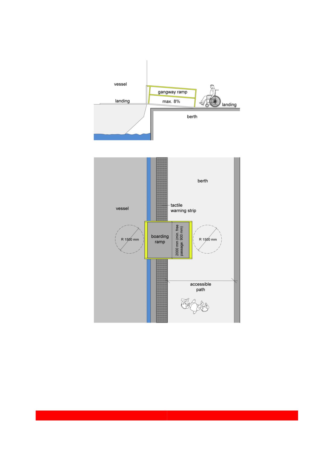
Figure 116. Access for marine vessel
213
12.5.2. Landside ramps
Landside ramps connecting the building with the berth shall be according to Section B
of this Code.
As a minimum, the berth should have a paved, slip-resistant surface with a sign post
indicating the vessel route. The front edge of the paved surface should have a bright
colored strip. If the berth is not leveled with the vessel, a gangway shall be provided.
Seating shall be provided for passengers to wait and rest.
A cover shall be provided to protect passengers from the weather.
12.5.3. Stations
Marine stations should have a minimum of a sheltered structure with a roof and
protected sides. Station buildings shall be accessible as per Section B of this Code.
A bench should provide seating with provisions for obese persons and pregnant women
without armrests in between seats, but with armrests at the end of the bench. A space
for a wheelchair/scooter should be 865 mm x 1400 mm.
A large print schedule and a route map should be displayed.
Transparent sides/windows should be provided for safety during day times, as well as
for safety by night with interior and exterior lighting.
A “Help” phone should be available for information and safety. A text option should be
available for people who are deaf.
Ticketing counters should have a section accessible for persons using wheelchairs at
the height of 780 mm. and shall have an induction loop for person with hearing aids.
Accessible washrooms shall be provided according to Section B of this Code.
Floors shall be non-slip and non-glare.
Schedules shall be provided in audio and visual displays.
214
13. School Buses
13.1. Considerations
A variety of vehicles are suitable to be used for accessible school transportation. This
includes low floor 10 meters long regular coaches, low floor 6.7 meters long medium
size buses, and low floor accessible taxis.
The school shall establish responsibility for the provision of services with the school bus
operator. A special dispatch center shall coordinate scheduling and coordinate with
parents in case of cancellations, emergencies and extreme weather. The use of the Nol
card for students with functional limitations shall be implemented with a discount fare.
For students with functional limitations, in particular those with mobility impairments,
transportation to and from school present a major obstacle due to the lack of accessible
school bus vehicles. As an alternative, accessible taxis can be used.
Drivers shall be trained for hands-on instruction on how to achieve effective securement
and occupant restraint.
The major obstacles for the school bus mode are the horizontal and vertical gaps
between the vehicle and the road. Students using walkers and wheelchairs require
boarding and securement systems. On board safety, emergency and evacuation/rescue
instructions in multiple formats throughout the vehicle are required to make the trip safe,
secure and stress-free for all students.
Access to an accessible school bus shall be universal and apply to the dimensions and
maneuvering characteristics of all persons using mobility aids, luggage, prams/ strollers,
service animals, including persons with vision, hearing and cognitive disabilities.
13.2. Boarding and alighting
13.2.1. Vehicle type
Accessible school buses shall have a front and center low floor section with kneeling
capability.
13.2.2. Doors
The door opening control shall be placed on the outside of the accessible door at a
maximum height of 1200 mm from the bus floor, and be operated by touch.
215
Clear horizontal door openings shall be a minimum of 850 mm, to accommodate
students with powered and non-powered mobility aids. This applies to single and
multiple leaf doors.
Handrails with contrasting colors shall be positioned on each side inside the door when
it is open, without interfering with the clear width of 850 mm of the door.
Audible warnings shall be provided to announce the opening and closing of vehicle
doors, which will be especially helpful for students who are blind or have reduced vision.
All students’ benefit from this assistance.
13.3. Ramp
In order to board the bus, a powered ramp shall be positioned at the door for the
students with functional limitations and those using a mobility aid board the bus.
Power operated ramps (sliding or swing-out) shall have interlock devices (only operable
when vehicle brakes are applied), emergency override, and supervised operation by the
driver.
The driver from his position shall operate the powered ramp.
The driver shall be trained to operate the securement system and the ramp.
An audio warning signal shall be applied for deploying and retrieving the ramp.
Ramps shall have a maximum gradient of 8% measured from the sidewalk level to the
ramp’s intersection with the floor of the bus for unassisted boarding.
The ramp width shall be a minimum of 900 mm.
The ramp shall have guards on each side, 50 mm in height with high contrasting colors.
The payload shall be 350 kg.
The ramp surface shall have an anti-slip surface.
13.4. Onboard circulation
13.4.1. Aisle width
The aisle width throughout the low floor sections of the bus shall be a minimum of 850
mm clear of protruding obstacles.
216
13.4.2. Wheelchair maneuvering spaces
Pathways for mobility devices, from the entrance door to the wheelchair location shall
be 850 mm wide.
A clear circle of 1500 mm shall be provided for the wheelchair to maneuver in and out of
the wheelchair station.
13.4.3. Handholds/ stanchions
Interior handrails and stanchions shall be located to permit sufficient turning and
maneuvering space for mobility aids to reach a securement location from the ramp.
These handrails and stanchions shall allow for safe boarding and alighting, provide
seating and standing assistance, and allow for easy circulation throughout the vehicle
for students with functional limitations. Handrails and grab bars shall have at each end a
tactile or Braille application for students who are blind.
Students with functional limitations shall be able to grasp handrails from outside the
vehicle to assist in the boarding process.
Handrails shall be between 30 mm and 40 mm in diameter, have corner radii of 3 mm or
greater, and have a clearance for knuckles of at least 35 mm from the nearest surface.
Where ramps are located at the front entrance, stanchions shall be located in such a
way as not to interfere or impede the wheelchair footrests.
13.4.4. Floor surface
The floor surface shall be covered with non-slip, non-reflective material.
Floor pattern design can be used for directional guidance or for designated space e.g.
mobility devices and luggage placement areas.
13.5. Seating
13.5.1. Wheelchair spaces
Each large bus over 6.7 m shall have at least four wheelchair positions to accommodate
students using a wheelchair/scooter.
Each wheelchair position shall have a clear length along the longitudinal axis of the bus
of 1400 mm and a clear width of 865 mm.
217
Side facing flip seats along the bus wall in the wheelchair position can be used when no
wheelchair student is occupying the location. These seats shall be of the bench type to
accommodate obese students. The seats shall always be in the up position and not
interfere with the clear width for the wheelchair of 800 mm. These seats shall not be
designated as Priority seats.
13.5.2. Securements
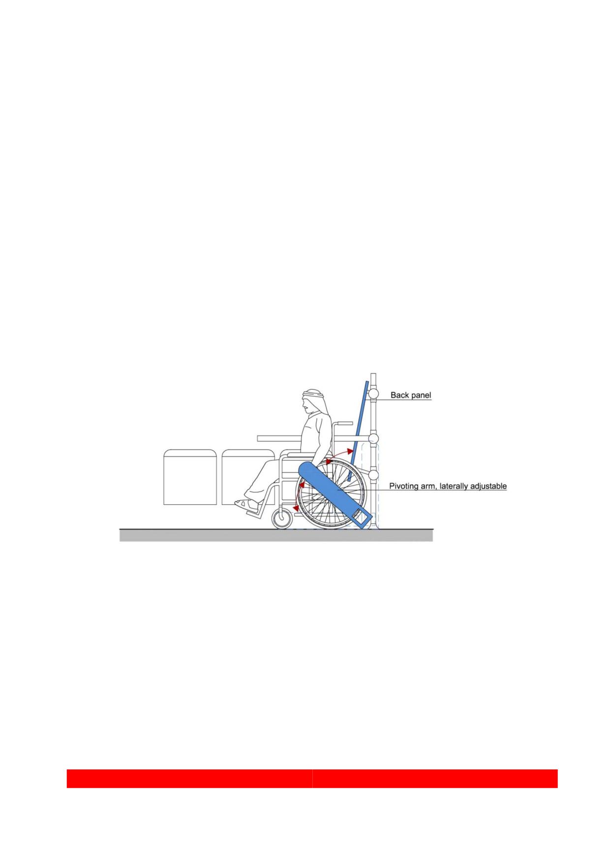
Each wheelchair position shall be fitted with a rear-facing securement system, where
the wheelchair and the occupant face the rear of the vehicle. The rear-facing system
shall be provided with a padded back panel and have the following dimensions:
Height of panel from floor to bottom edge: 350-480 mm
Height of panel from floor to top edge: 1300 mm min
Width of panel: between 250 mm and 400 mm
Figure 117. Rear-facing securement with pivoting aisle arm - securement technology for
low transportation in buses and rail
The back panel shall withstand a decelerating force of 3 g. The rear-facing securement
shall have a pivoting aisle arm, which is also laterally adjustable to accommodate
different wheelchair types and prevent them from moving longitudinally and laterally.
The vehicle shall be fitted with a horizontal handrail along the longitudinal side of 750
mm - 1000 mm from the floor, not to exceed the mobility aid space by more than 90
mm, and have a diameter of 30 mm - 40 mm with a clear knuckle space of 35 mm
between any part of the vehicle and the handrail. Handrails and grab bars shall have at
each end a tactile or Braille application for students who are blind.
218
The wheelchair position shall have a call button to alert the driver, mounted on the bus
wall or on the horizontal grab bar at a height of 750 mm - 1000 mm from the floor. The
call button shall be operated by touch.
13.5.3. Stop announcements
A Next Stop audio and text display shall be provided to be visible from their position.
13.5.4. Priority seating for non-school use
This will only be required if the RTA or a private school bus is used for other purposes.
At least two priority seats shall be located close to the driver and entrance door. The
seats shall be reserved for persons who have mobility, sensory or cognitive disabilities
and seniors. Hip-to-knee room shall be no less than 675 mm in front of the seat in a
forward-facing position.
Each priority seat or mobility aid position shall be equipped with stanchions, handholds,
or handrails.
Each bus shall contain sign(s), which indicate that certain seats are priority seats for
seniors and persons with functional limitations. Other passengers shall make such seats
available to those who wish to use them. Priority seats shall not be located in the area
of the wheelchair station.
13.5.5. Seat surfaces
Sitting surfaces, especially those of aisle-facing seats, shall be covered by materials
with a coefficient of friction sufficient to prevent students from sliding back and forth
during sudden starts and stops.
The seat profile shall be ergonomically contoured.
Bench seats shall be provided for large/obese students without armrests between seats.
There shall be a compartment for bags and storage for canes and crutches, provided
that it neither obstructs students’ movement nor falls on students in cases of a sudden
stop, accidents or during the normal bus movement.
13.5.6. Specifications of seats and bus interior
The number of seats specified by the manufacturing company shall be adhered to, and
no collapsible middle seats to be used.
219
The side hand rests; arm support, and any other solid materials shall be removed from
the back side of seats.
The two doors of the bus shall be fitted with handrails to assist in the boarding process.
The driver shall control the door opening and closing mechanism, and electronic control
is preferred.
13.6. Illumination, lighting, signage
13.6.1. Lighting
When the vehicle door is opened, 30 lux of illumination as measured on the step tread
or ramp platform shall be provided.
All vehicle doorways shall have outside lights that illuminate when the door is opened
and provides at least 10 lux of illumination on the street surface for a distance of 1000
mm perpendicular to the bottom step tread or ramp outer edge. These light(s) shall be
shielded to protect the eyes of students coming in or out.
13.6.2. Visual elements
Reflectance values over 30 LRV points shall be used for signage and for tactile
warnings at folding seats. Specific colors shall be selected for students who are
colorblind and may only see red and green as gray.
Uniform signage shall be provided for all students, who may not be able to read text.
13.7. Onboard information and safety
13.7.1. Alternative formats
Audio, text and sign language displays and inductive loop systems for information shall
be used to address the needs of students, deaf/heard of hearing, blind/vision-impaired
and cognitively impaired.
Noise level inside the bus shall not exceed 70dB(A) to avoid speech interference.
Technologies shall be considered to interface between driver announcements and
personal communication devices (e.g. phones/tablets) via Bluetooth or similar systems
for real time audio and text display.
220
13.7.2. Emergencies and evacuations
Clearly posted evacuation and emergency warnings and instruction, in 14-point print, in
electronic text, and in video formats with sign language shall be provided in the vehicle.
Safety announcements shall be made in visual and audio format in case of emergencies
and evacuations. For students with hearing impairments, inductive loop shall be
installed within the vehicle.
Safety drills shall be conducted at least twice a year, involving students with functional
limitations.
13.7.3. Bus safety standards
All seats shall have elevated backrests of at least 710 mm high. The distance between
seats shall not be less than 640 mm and the size of the seat shall not be less than 400
mm (a single seat) and 900 mm (double seats). Triple-seats are prohibited in school
buses.
All seats shall be padded from all sides and made from shock-absorbing & fireproof
pads.
13.8. Service animals, smoking and allergens
13.8.1. Service animals
Space shall be provided for service animals out of harm’s way close to their patron.
13.8.2. Food & smoking, allergens
Food consumption and smoking is forbidden on all school buses.
Allergy considerations shall be observed
In the event of a passenger identifying his/her allergies to the driver, he should make an
announcement to the other passengers to observe the allergy condition. He should then
set up a buffer zone.
221
13.9. Group travel
13.9.1. Group vehicle
A single level coach shall be equipped with the following features:
Ramps at service doors.
Side facing flip seats on both sides of the low floor sections of the bus.
4 rear-facing wheelchair securement systems, 2 on each side.
222
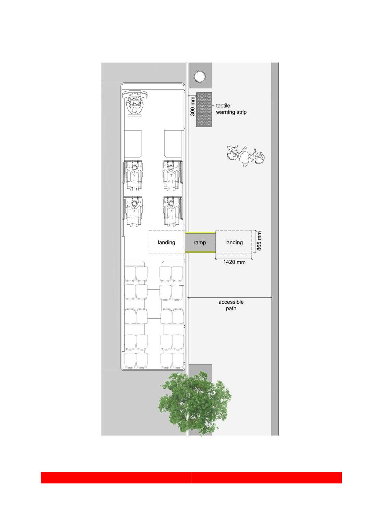
Figure 118. School bus layout and interface with infrastructure
223
13.9.2. Conductors or attendants
There shall be a team of two-person staff (conductors or attendants) to assist in
deploying securement systems, and to act as safety monitors (Ref. Item 10).
Training of staff performing the above duties is mandatory.
13.10.Vehicle infrastructure interfaces
13.10.1. Stops
As a minimum, stops shall have a paved, non-slip surface. On public bus stops, the
front edge of the paved surface shall have a bright colored strip. If the sidewalk is not
leveled with the road, a curb cut shall be provided. Stops shall be located in an area
with cover/shade to protect against weather elements.
13.10.2. Shelters
Bus shelters shall consist of a minimum sheltered structure with a roof and protected
sides. The platform surface shall be flat, level, slip-resistant and solid.
A bench shall provide seating with provisions for obese students without armrests in
between seats, but with armrests at both ends of the bench. A space for a
wheelchair/scooter shall be 900 mm x 1500 mm to enter, turn and exit.
There shall be a minimum depth of 2700 mm from the curb for a wheelchair/scooter to
board a vehicle over a ramp (Fig. 24).
Along the front edge of the platform shall be a tactile warning surface with color
contrast, aligned to the place where the bus door shall be when parked.
Transparent sides/windows shall be provided for safety during day times, as well as for
safety by night with interior and exterior lighting.
A “Help Line” phone shall be available to provide information and help, with text
capabilities.
224
14. Accessible taxis
14.1. Considerations
The present supply of 7 accessible taxis is severely lagging behind the demand. It
resulted in long waiting time of an hour or more. This will be exacerbated by the
anticipated increased demand by visitors for EXPO 2020. There is also a need to
provide accessible taxis for intercity service. The major technical and customer service
obstacles are the dated technology of present accessible taxis, a lift- equipped rear
boarding system with limited headroom for the user. With only one space for wheelchair
per vehicle, it prevents two persons in wheelchairs, e.g. a couple, travelling together in
the same vehicle. Although it is mandatory to use the wheelchair securement system,
some users refuse its use. In the case of female passengers, a male driver would be
unable to help with the boarding process or the tied down of securement belts due to
social cultural considerations. A female driver is required to service female clients with
disabilities.
Onboard information and communication alternatives for sensory-impaired passengers
should be provided as well as fare payment options. Fare payment methods should
account for persons with limited agility and vision. The use of Nol cards has recently
been introduced to facilitate fare payments. Designated pick-up and drop-off places
should be made available to facilitate seamless interface.
Access to an accessible taxi shall be universal and apply to the dimensions and
maneuvering characteristics of all persons using mobility aids, luggage, prams/ strollers,
service animals, persons with vision, hearing and cognitive disabilities.
New technologies shall recognize the development of driverless cars, and in the case of
accessible taxis they can be automatically driven but will always need a driver to assist
passengers with disabilities.
14.2. Boarding and alighting
14.2.1. Vehicle
Accessible taxis shall have a low floor and accessible doors on both sides with ramps
that should be used where possible to accommodate the full height of a large person in
a wheelchair with clear headroom, and persons with strollers.
The international symbol of access shall be placed on the side passenger door and rear
window.
225
Raised taxi registration numbers are to be placed on the exterior passenger doors.
Low floor taxis with side doors facilitate easier boarding from curb level with less ramp
gradients than rear door taxis that board from the road level and require a longer ramp.
The vehicle shall be equipped with a Body Fluid/Spill Kit and a First Aid Kit.
14.2.2. Vehicle capacity
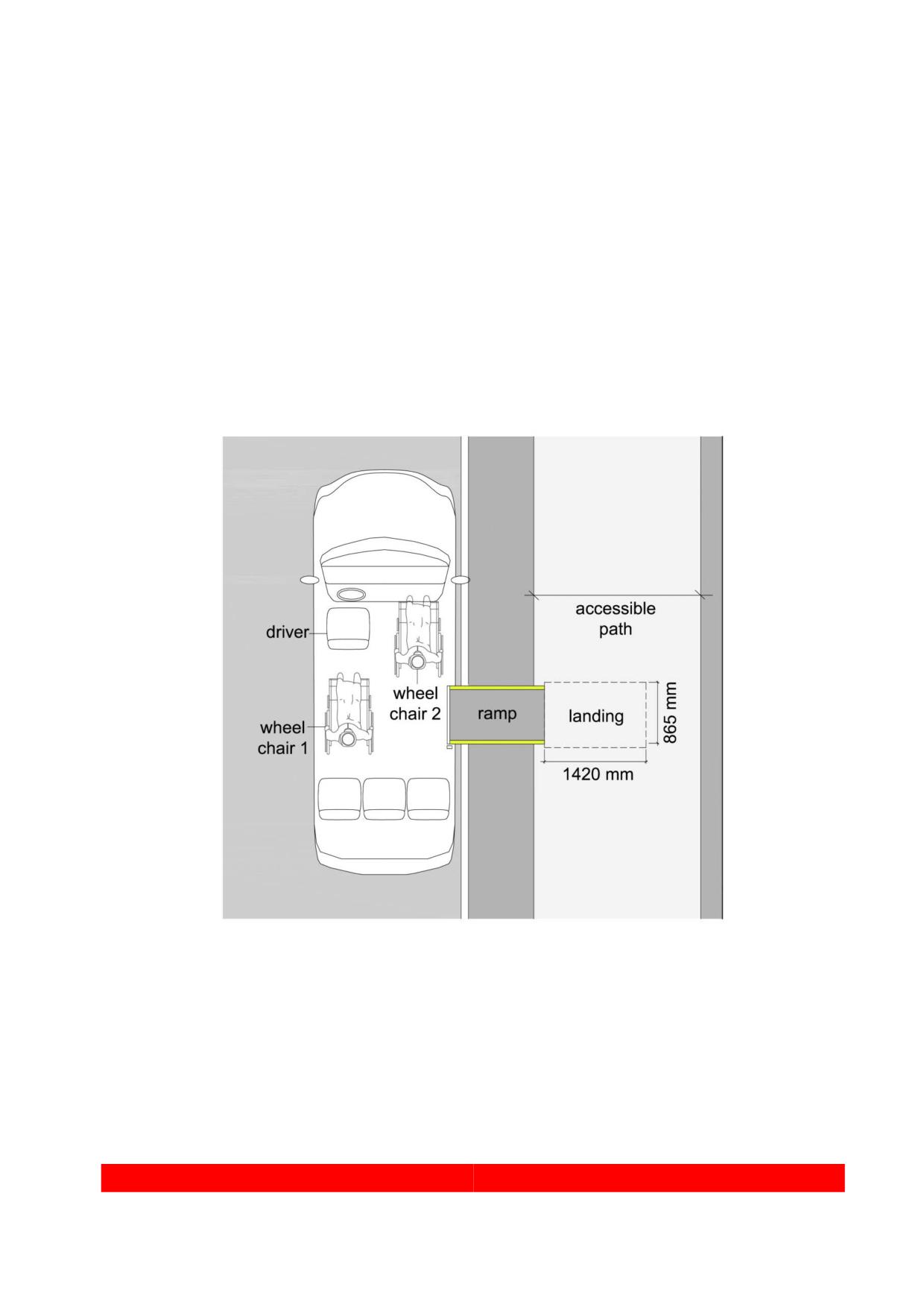
The accessible taxi shall have the capacity of carrying at least 2 persons in a
wheelchair, and provide additional regular seats.
Figure 119. Accessible Taxi lay-out for two passengers in wheelchairs
14.2.3. Doors
Clear horizontal door openings shall be a minimum of 810 mm.
Handrails with contrasting colors shall be positioned on each side inside when door is
open, without interfering with the clear width of 810 mm of the door.
226
Doors must have an unobstructed vertical height of at least 1500 mm.
14.2.4. Ramp
A manual or power-assisted boarding device shall be available at any accessible
entrance to a taxi that has a vertical rise exceeding 12 mm or a horizontal gap
exceeding 40 mm.
A ramp shall be positioned at the door for persons with functional limitations and those
using a wheelchair to board/alight the taxi.
Manual or power operated ramps (sliding or swing-out) shall have interlock devices
(only operable when the vehicle brakes are applied), emergency override, and
supervised operation by the driver.
The driver shall operate the ramp.
An audio warning signal shall be applied for deploying and retrieving the ramp.
Ramps shall have a maximum gradient of 8% measured from a level ground surface to
the ramp’s intersection with the floor of the taxi. The ramp width shall be a minimum of
900 mm.
The ramp shall have guards on each side, 50 mm in height with high contrasting colors.
The payload shall be 350 kg.
The ramp shall have an anti-slip surface.
The ramp shall be firmly attached to the vehicle so that it is not subject to displacement
when loading or unloading a heavy mobility device and that no gap between the vehicle
and ramp exceeds 15 mm.
The ramp shall be stowed in such as manner as not to pose a hazard to passengers or
impinge on passenger’s mobility device.
14.2.5. Handrails and grab bars
Handrails and grab bars shall be provided at the entrance of the vehicle which allows
people to grasp them from the outside the vehicle while boarding, and to continue using
them throughout the boarding and alighting process.
227
14.2.6. Driver’s role
The driver shall be responsible for the safe operation of the ramp, as well as for the
deployment and detachment of the wheelchair securement and passenger occupant
restraint system.
The transportation provider should ensure that the driver provide routine
boarding/alighting assistance to passengers with disabilities when required in
accordance with Islamic custom without jeopardizing the health and safety for both
parties. This includes assisting the passenger in a wheelchair into the securement
position or transferring the passenger from a wheelchair into a seat.
The transportation provider should ensure that drivers do not request the assistance of
other persons, other than personal care attendants, for routine boarding/alighting
assistance for a passenger with a disability except upon the requests or consents of the
said passenger.
All drivers should be trained in disability awareness and on how to properly secure a
person in a wheelchair
14.2.7. Wheelchair space
A minimum floor space of 760 mm in width and 1500 mm in length including the space
for front and rear straps shall be provided for each wheelchair space.
A clear turning circle of 1500 mm shall be provided for the wheelchair to enter and exit
to and from its position.
14.2.8. Wheelchair securement
A forward facing securement shall be available for each wheelchair position, consisting
of 2 front and 2 rear straps connected to the vehicle floor.
228
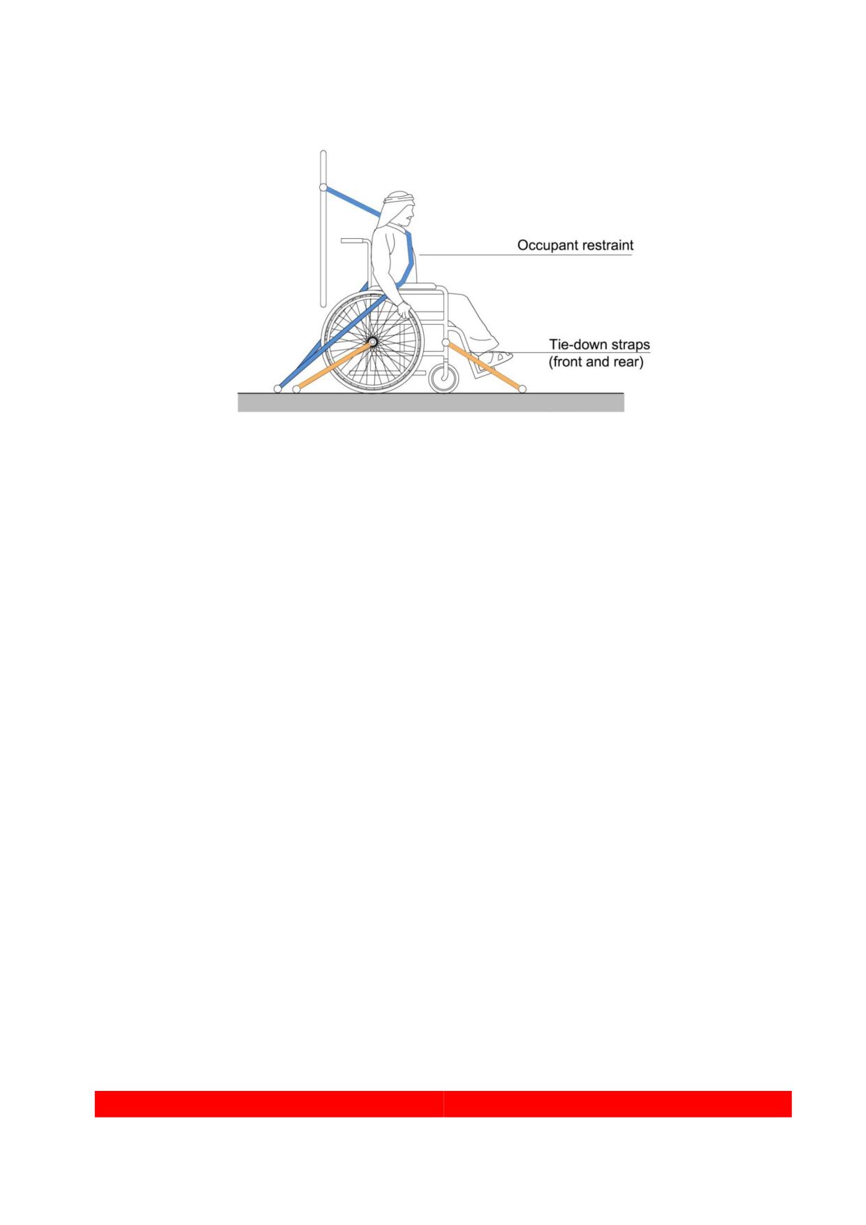
Figure 120. Forward facing securement with occupant restraint
An occupant restraint system for the person in the wheelchair shall be applied,
consisting of a three-point belt and lap system, separately anchored to the floor and wall
of the vehicle.
14.2.9. Floor surfaces
All floor surfaces where passengers walk and at the securement locations shall have
slip-resistant surfaces.
The floor of the wheelchair space is to be flat and level.
14.2.10. Fare structure & payment
Rates and communication or emergency information notices should be clearly posted
for persons with sensory impairments and foreigners.
For passengers with sensory, cognitive-impairments, foreigners and illiterate persons,
the transportation provider should provide alternative means of communicating fare
information, such as talking meters, and onboard induction loop systems. Fare display
should be in text and audio format. The vehicle should be equipped with a printer for the
issuance of receipts.
Pen and paper should be made available at all points of contact between the driver and
passengers in order to facilitate communication.
229
Prepaid proximity cards with discounts for persons with functional limitations - The RTA
Nol cards - that require less hand dexterity and benefit persons with limited mobility
could be used.
Discounted Nol cards for visitors with functional limitations shall be available at the
Emirate’s entry points, especially in view of the upcoming EXPO 2020.
14.2.11. Pick-up and drop off points
Where a passenger is unable to board/alight at a designated accessible stop because
of a temporary barrier, the transportation provider should ensure that the driver allows
passengers to board/alight at the next available safe location. This is especially
important in unpaved areas.
14.2.12. Emergency and evacuation
Clearly posted evacuation and emergency warnings and instruction, in large print and
should be provided in the vehicle.
14.2.13. Service animals, food, smoking
The following types of service animals shall be transported with their patrons.
1. Guide dogs trained by a guide dog organization
2. Hearing dogs
3. Comfort animals
Smoking and food consumption are forbidden in all accessible taxis.
14.2.14. Vehicle interfaces with stops and stands
Designated stops and stands for accessible taxis shall be available at major trip
generators, e.g., Metro, Tram, Bus, Marine stations, shopping malls, places of worship,
hospitals, government buildings, universities, etc.
Accessible taxi stands and stops should have at least a signpost with a telephone
number, fare structure and street name. Stops should have a paved, slip-resistant
surface. The front edge of the paved surface should have a bright colored band. If not
leveled with the road, a curb cut should provide access for disabled and elderly
persons. Stops shall be covered against sun and heat and include a bench for seating.
230
14.2.15. Door lighting
Vehicle doors in which a ramp is installed shall have outside light(s), which when the
door is opened, provide at least 10 lux of illumination on the street surface for a distance
of 1 meter perpendicular to the ramp. Such light shall be shielded to protect the eyes of
entering and exciting passengers.
Illumination is to be provided from the top of the door or depending on the configuration.
231
232
Section D
Wayfinding
233

Section D - Wayfinding
Previous sections of this Code have already covered the aspects related to the
identification of the accessible path and the prevention of risks by means of tactile
warning pavements and obstacle identification.
In this section the process of wayfinding is addressed.
Wayfinding encompasses all of the ways in which people orient themselves in physical
space and navigate from place to place. When there is a well-designed wayfinding
system, people shall be able to understand their environment. This provides users with
a sense of control and reduces anxiety, fear and stress.
Wayfinding can be particularly challenging for some people with disabilities. For
example, someone who is deaf or hard of hearing will rely on visual information but may
not be able to hear someone providing directions. Someone who is blind will not be
able to see a directory, but if it is in a predictable location and has information in a tactile
format, they can read it and they will use sound and even smell to gather more
information about their environment.
It is important to provide wayfinding information in a variety of different formats as
visual, auditory, olfactory and physically. All people use different forms of information
gathering to find their way to their destination but this is especially important for people
with disabilities.
From the user perspective, the wayfinding process involves four stages:
Wayfinding process
1 Orientation
Is the attempt to determine one’s own location in a
concrete space in relation to the chosen destination
2 Route decision
Is the selection of a course of direction to the destination
3 Route monitoring
Is checking to make sure that the selected route is
heading towards to the destination.
4 Destination recognition
Is when the destination is recognized
Table 11. Wayfinding process
234
14.3. General aspects
Considering the diversity of the population visual, acoustic and tactile references shall
be used to guide a person to avoid risks and to reduce confusion.
Signs with texts and symbols, visual references, tactile information like high-embossed
characters or Braille text are the elements that shall be used.
Although technological means like smartphone Apps can be a very valuable tool to
assist in the wayfinding process, these are not described in this Code.
The elements to be used to assist a person in the wayfinding process shall guarantee
that:
1. Every person, even a person with low vision, can easily identify in which part of
the city or building they are in at a concrete moment, without walking more than
70 meters in open spaces and 30 meters inside buildings.
2. All park entrances shall display the main facilities in a visual and tactile map.
3. All business and administration buildings shall display the name of the building in
the façade and a provide a directory in the hall listing the companies or services
contained in the facility.
4. In buildings, orientation signs to the exit, toilet and other services shall be present
at any corridor intersection at every 30 meters.
5. All door frames shall provide information about the service provided in the space.
From a design point of view, the following general design requirements shall be taken
into account:
1. Avoid visual clutter due to inappropriately designed or located signage and other
elements in the environment.
2. Communicate the environment’s identity clearly and consistently through the
design of graphic elements to increase the users’ recognition and sense of
confidence in the signage system during navigation.
3. Signage information on a sign should be kept to the minimum and organised with
hierarchy, without duplication. Complex information should be broken down,
beginning with general information and moving towards more specific
information.
235
4. Colour coding should be used to differentiate zones or hierarchies of text
messages. Colours that create confusion in case of colour blindness should be
avoided.
5. Standardised nomenclature should be adopted to organise information in similar
environments.
6. Signage should be positioned at key decision-making points on the path of
movement. It should be positioned over the path of travel at a height well above
head level in high pedestrian traffic areas, but in a manner that a person in a
wheelchair or a child can see it easily. Signage should be positioned to avoid
shaded areas and glare.
7. Letters, numbers, symbols and pictographs should be glare-free and presented
in high reflectance contrast.
8. Illuminated signs where the text is light on a dark backg0round shall be avoided.
9. Printed characters shall be placed on top, centred (where there is only one word)
and aligned to the left (when there is more than one word).
10. When both Arabic and English languages are used, being Arabic being the
primary language texts shall be aligned to the right.
11. Braille characters will be located at the bottom left, at a minimum distance of 10
mm and a maximum of 30 mm from the left side and bottom of the sign.
Accessibility pictograms shall follow the ISO 7000: 2004 standard.
12. Safety and evacuation pictograms in workplaces and public places shall follow
the ISO 3864-1: 2002 international standard.
13. If signage is supplemented with Braille, it should be located at the bottom of the
sign and presented in Grade One Braille that meets the standards in English.
14. Wayfinding signage is classified into the following categories according to the
wayfinding processes required for the users:
236
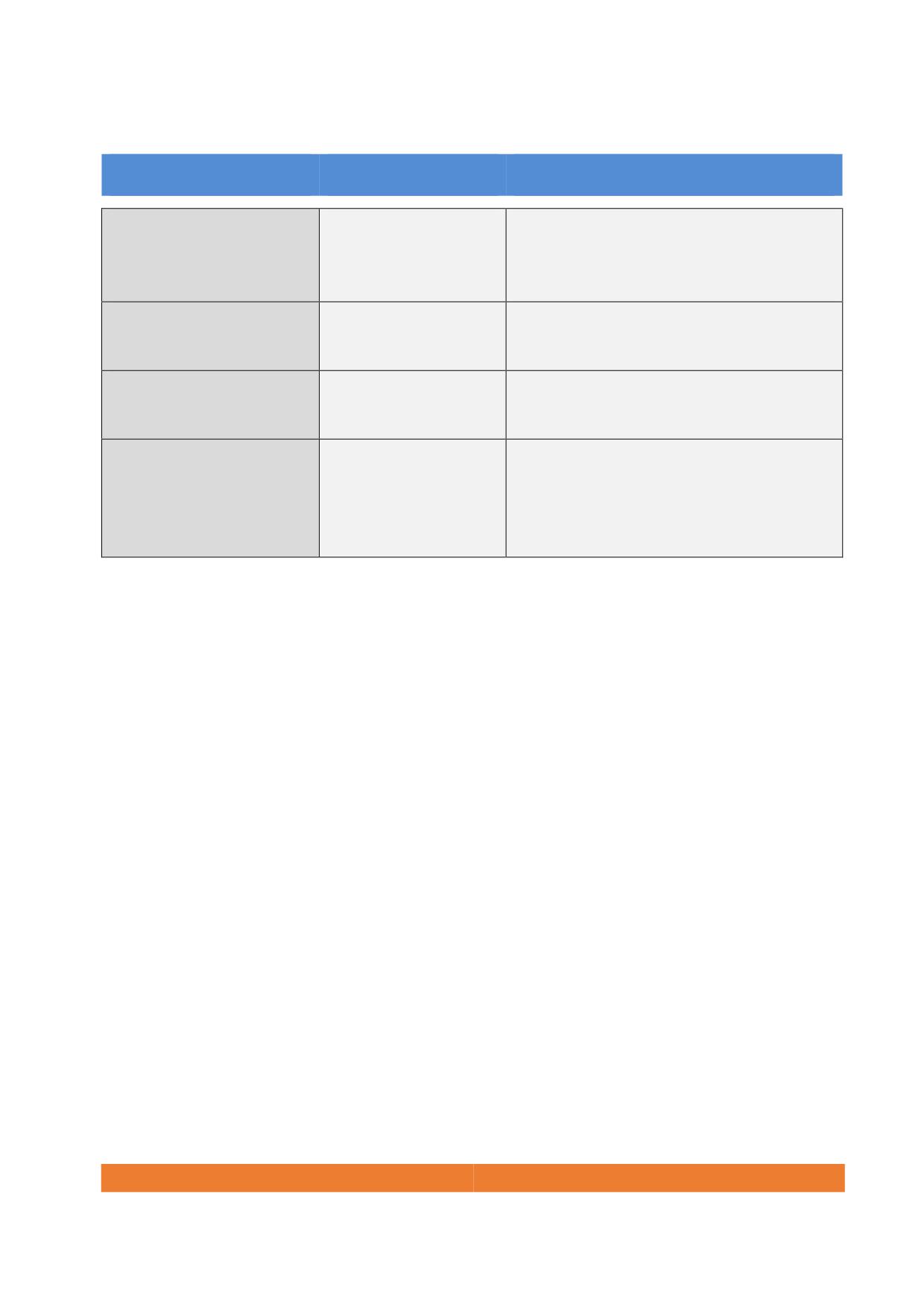
Wayfinding processes
Sign type
Use of the sign
Orientation
Information sign
Indicates specific locations within an
environment, helping in
understanding.
Route decision and
Directional sign
Guide users through the environment
monitoring
to their destination.
Recognition
Identity sign
Display necessary information for
users to identify a place.
Advice
Advisory sign
Draw attention to objects, situations or
behaviours that may affect the well
being and convenience of users or
operations in the environment.
Table 12. Sign types according to wayfinding processes
14.4. Information signs
Information signs are meant to inform the user about their own position relating to their
destination. Therefore, it is necessary that:
At any street corner the name of the street in both Arabic and English shall be posted.
• Information about the nearest means of public transport and the distance to them
shall be displayed at least at every second street corner
• A map of the community containing the main services within this community and
a map showing the position of the community in relation with the city shall be
displayed in all bus shelters, metros, tramways and ferry stations.
• Information displaying the nearest exit, nearest toilets and the distance to them
shall be displayed at least every 70 meters in all parks.
• All maps presented in open spaces shall be designed with the North in the upper
part and displaying a North symbol.
• Maps and directories shall be mounted in entrances to help visitors to navigate.
• Maps shall be easy to understand, without too much information and they shall
use contrasted colours and symbols.
237
14.4.1. Tactile maps
Tactile maps that offer embossed visual information and acoustic information should be
provided when required. Acoustic information shall also be provided when possible.
14.4.1.1. General features
Tactile maps shall include only essential information: location of services and paths and
position of elements such as information, main services, toilets, etc.
Concepts used should be easy to understand.
Graphic plane representation (lines, surfaces) should be defined through embossment,
textures and colour contrasts.
The signs and lettering of the map shall be represented taking into account contrast
between fonts and backg0round colours. The font size shall be at least 20 mm in a sans
serif type font. Furthermore, the information shall be represented in Braille.
The maximum dimensions of horizontal fixed tactile maps will be of 800 mm x 450 mm.
The symbols should be clearly differentiated (form, colour and texture) and shall be
easily associated with their representation.
For complex maps buttons providing oral information shall be provided.
14.4.1.2. Location of tactile maps
When a tactile map is provided, it will be located within the accessible path and its
location shall be indicated with a tactile orientation and warning surface. It should be in
a well-lit area. Obstacles in front shall be avoided such as glass protections.
When they are mounted in busy public places, they shall include sound information.
In large buildings and open spaces for public use (parks, beaches), they shall be
located at the main entrance area, near the door, on the right side, within 1000 mm. In a
building with more than one floor, it shall be located near the stairs or the elevator.
When fixed to a vertical surface, it shall be centred between 1250 mm and 1750 mm
above the floor. On horizontal or inclined surfaces, the height shall be between 900 mm
and 1200 mm from the floor and the inclination will be between 30º and 45º from the
horizontal level.
238
14.4.2. Digital screens
Screens should be matt and with a wide angle of vision and provide a good contrast. In
all instances, screens must fulfil the following criteria:
Whenever installed in walls, screens should be located at a height between 1700 mm
and 2000 mm without interfering with the accessible path with a slight inclination (15º-
30º). They should be visible from a minimum distance of 1000 mm, applying the
requirements of size and contrast specified in this Section.
An interaction space shall be provided in front of the screen.
14.5. Directional signs
Directional signs shall give information to the users how to reach their destination.
14.5.1. Directional arrows in directional signs
An acceptable arrow design shall have the shaft longer than the header stem.
Moreover, the thickness shall be the same in all arrow lines and header lines shall have
an angle of 45 degrees.
Figure 121. Example of a good arrow design
The table 13 shows the different arrow typologies allowed depending on the direction
they point to and the arrow alignment on the sign. Furthermore, the table shows the
hierarchy of arrows from the top to the bottom of a sign.
239
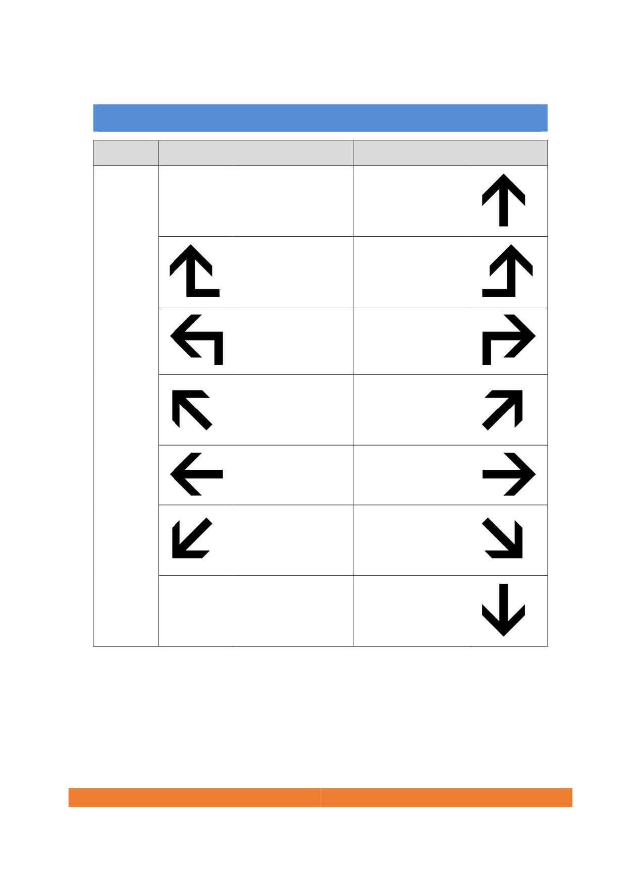
Arrow alignment, typology and hierarchy
Hierarchy
Arrows to be aligned on the left
Arrows to be aligned on the right
Top of
Straight up
the sign
To the left, then
To the right, then
ahead
ahead
Ahead, then to the
Ahead, then to the
left
right
Go up on the left
Go up on the right
Turn left
Turn right
Go down on the
Go down on the
left
right
Bottom of
Go down ahead
the sign
Table 13. Arrow alignment, typology and hierarchy
240
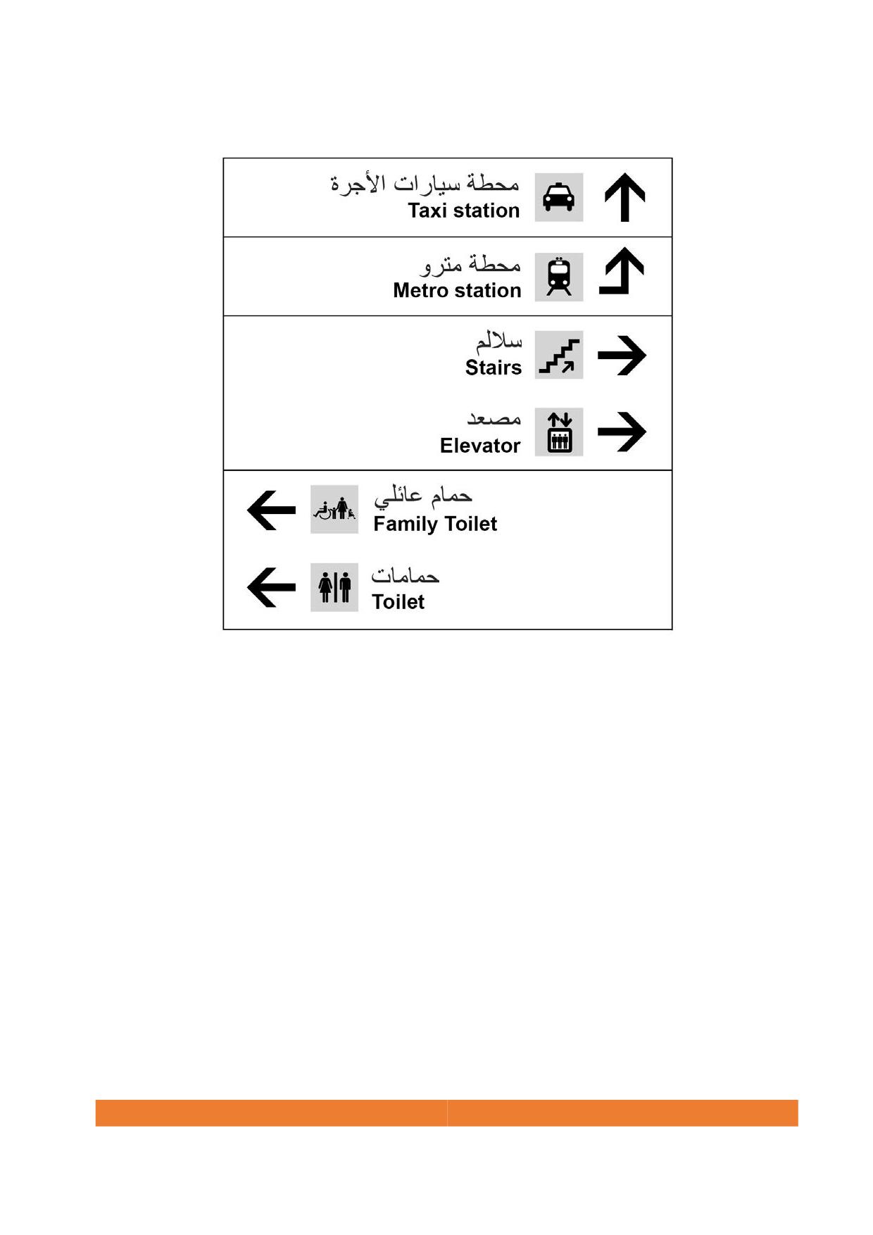
Figure 122. Example of a directional signs with the correct alignment and hierarchy of
arrows
14.5.2. Tactile wayfinding
Tactile wayfinding is very useful for people with low vision and people who are blind if
they use a white cane.
Tactile references include walls, façades, doors and changes of texture in pavements
and differences between tiles and grass.
241
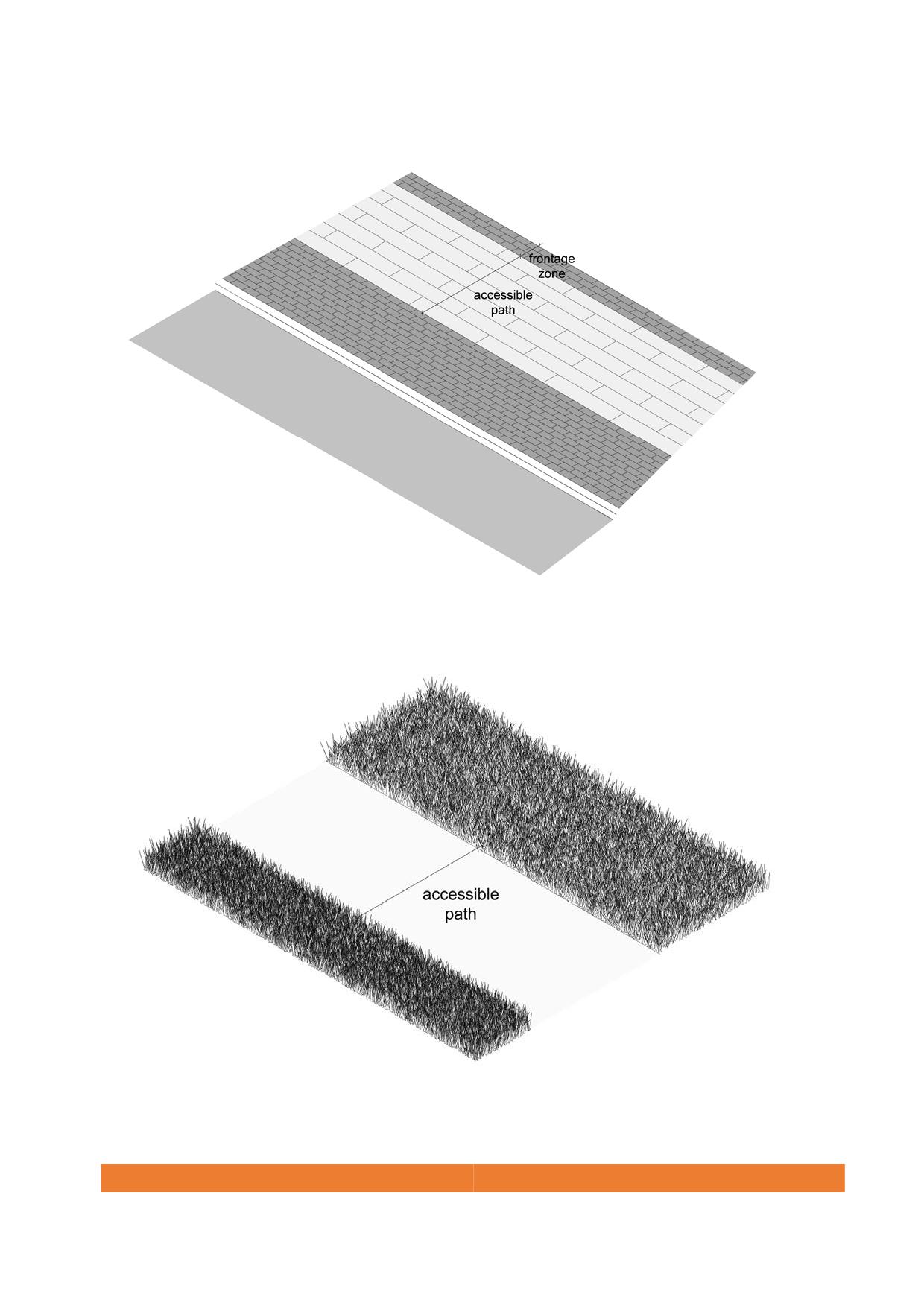
Figure 123. Accessible path pavements with different textures from the surrounding
pavement
Figure 124. Accessible path pavement with a different texture than the grass
242
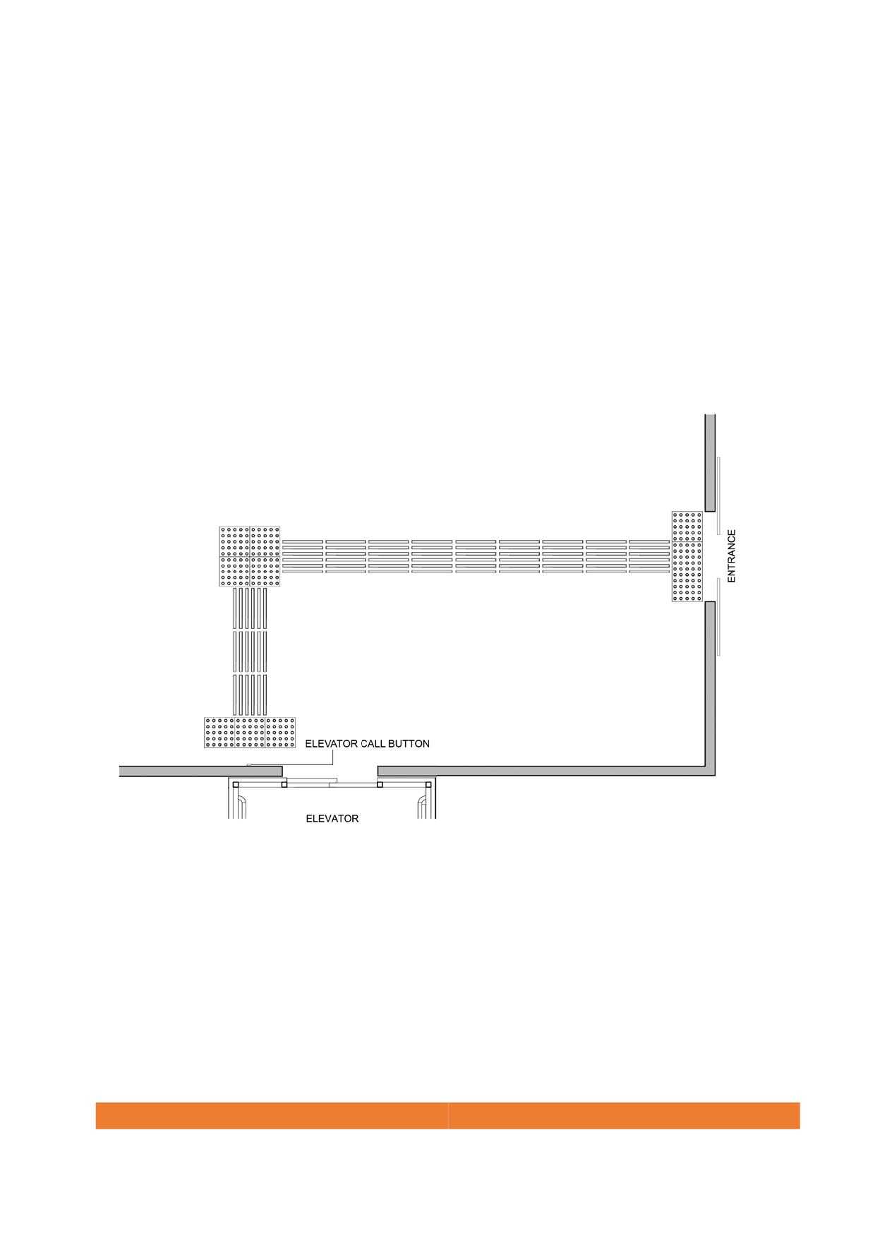
When differences in surface treatments are missing, a guiding tactile pavement as
described in Section B shall be provided.
Guiding surfaces pavements are compulsory in:
• Open squares without defined walking paths.
• Metro, tramway and ferry networks.
• From building entrances to information desks or receptions in administration
buildings.
Figure 125. Use of tactile pavement
Where public transportation is provided, guiding tactile surfaces shall start at the
entrance and be continued to all accessible services. The surfaces indicate the walking
route. Warning tactile surfaces shall be in place at any direction change, at any level
change and in front of all the services provided.
243
14.6. Identity signs
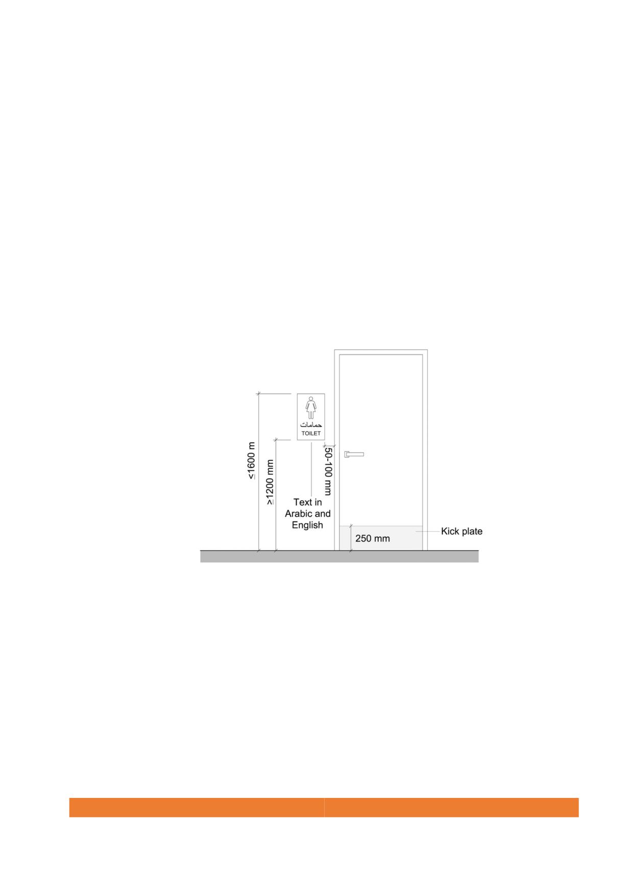
Identity signs are meant to identify a destination. Therefore, is it necessary that:
• All fenced open spaces like parks, golf courses or hotels shall display their name
at the entrance door.
• All building façades shall display the name of the building as well as the Makani
number.
• All doorframes shall present information on the service(s) available in the space.
Embossed standardized pictograms and text with contrasted colour must be
used to identify the different services. Signage must be mounted at a height
between 1200 mm and 1600 mm on the left of the door.
Figure 126. Doors signage
14.7. Advisory signs
Advisory signs shall be mounted to indicate safety procedures such as fire escape
routes, no smoking areas and other regulatory information.
Advisory signs shall also be placed at rest areas, lifts, access points, etc., to inform
users about giving priority or give way to others (such as the elderly, people with prams,
pregnant women and persons with disabilities).
244
14.8. Colour and contrast
Colour contrast between text and its backg0round shall have a clear reflectance contrast
of at least 50 LRV.
14.9. Typography
1.
In public spaces internationally recognizable icons and signs are preferred instead of
text.
2.
All relevant textual information will be provided both in Arabic and English. When
numerals are used at least English numerals will be displayed.
3.
Sans-serif fonts as Arial, Tahoma, Verdana, Avenir and Avenir Heavy shall be used.
4.
Within a sign, not more than 2 typefaces should be used.
5.
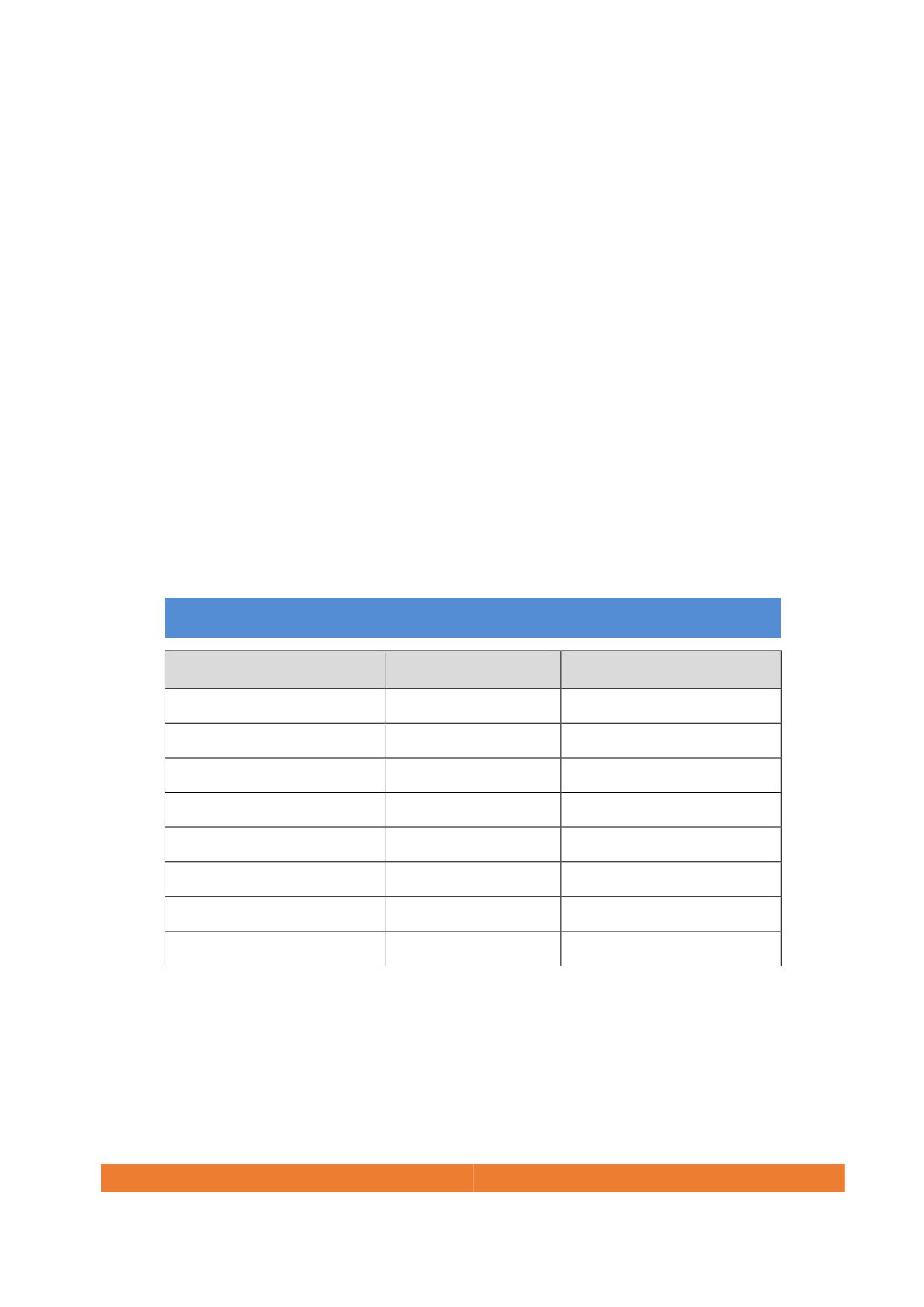
The distance at which a person can read the sign has to be taken into account
adjusting the font size according to the following table:
Signs font size according to reading distance
Reading distance
Minimum size
Recommended size
≥50 meters
170 mm
200 mm
20 meters
140 mm
180 mm
5 meters
70 mm
140 mm
4 meters
56 mm
110 mm
3 meters
42 mm
84 mm
2 meters
28 mm
56 mm
1 meter
14 mm
28 mm
0.5 meters
7 mm
14 mm
Table 14. Accessible text according to reading distances
6.
Signs should present chromatic contrast against their backg0round where it is located
and between the texts or icons and the sign backg0round, avoiding reflections.
7.
Only long texts should be aligned to the left in Latin languages and to the right in
Arabic language.
245
8. For short texts, tactile format following the criteria explained in section 1.10. must be
used when the sign is located in the hand interaction space (in vertical parameters,
between 1250 mm and 1750 mm and in horizontal parameters, between 900 mm
and 1250 mm).
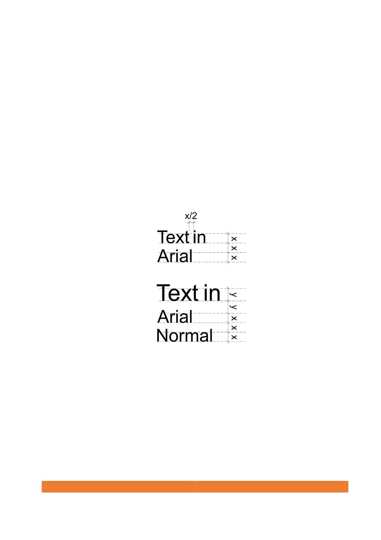
14.9.1. Layout and line spacing
Layout and line spacing shall fulfil the following criteria:
1. Line spacing shall be identical to the height of the lowercase letters.
2. When more than one letter size is used, the larger text height should be referenced
to determine the line spacing between different letter sizes.
3. Word spacing shall be a maximum of 0.5 times the height of the lower-case letters.
Figure 127. Line and word spacing
14.10.
Symbols
1. Accessibility pictograms and symbols shall follow the ISO 7000: 2004 standard.
2. Standard symbols can be used independently or combined with text messages,
where appropriate. Text messages may facilitate the understanding of less well-
established symbols.
246
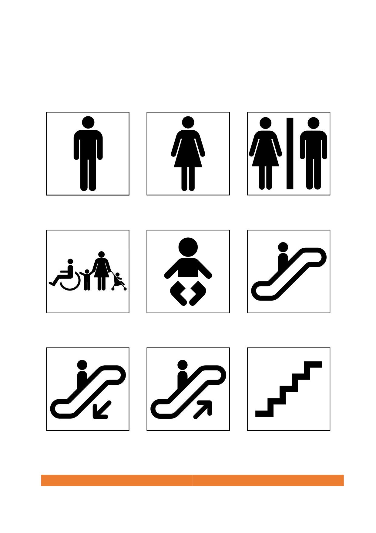
3. For short text messages, symbols shall be placed as a prefix to the description in
text.
4. Examples of symbols that should be use:
1. Male toilet
2. Female toilet
3. Toilet
4. Family toilet
5. Nursery
6. Escalator
7. Escalator down
8. Escalator up
9. Stairs
247
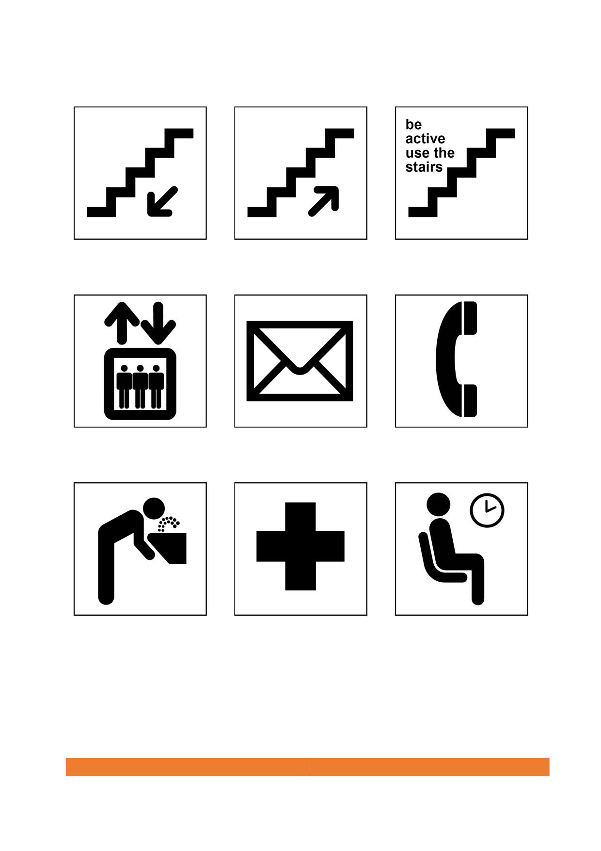
10. Stairs down
11. Stairs up
12. Stair with message
13. Elevator
14. Post Office
15. Telephone
16. Drinking Fountain
17. First Aid
18. Waiting Area
248
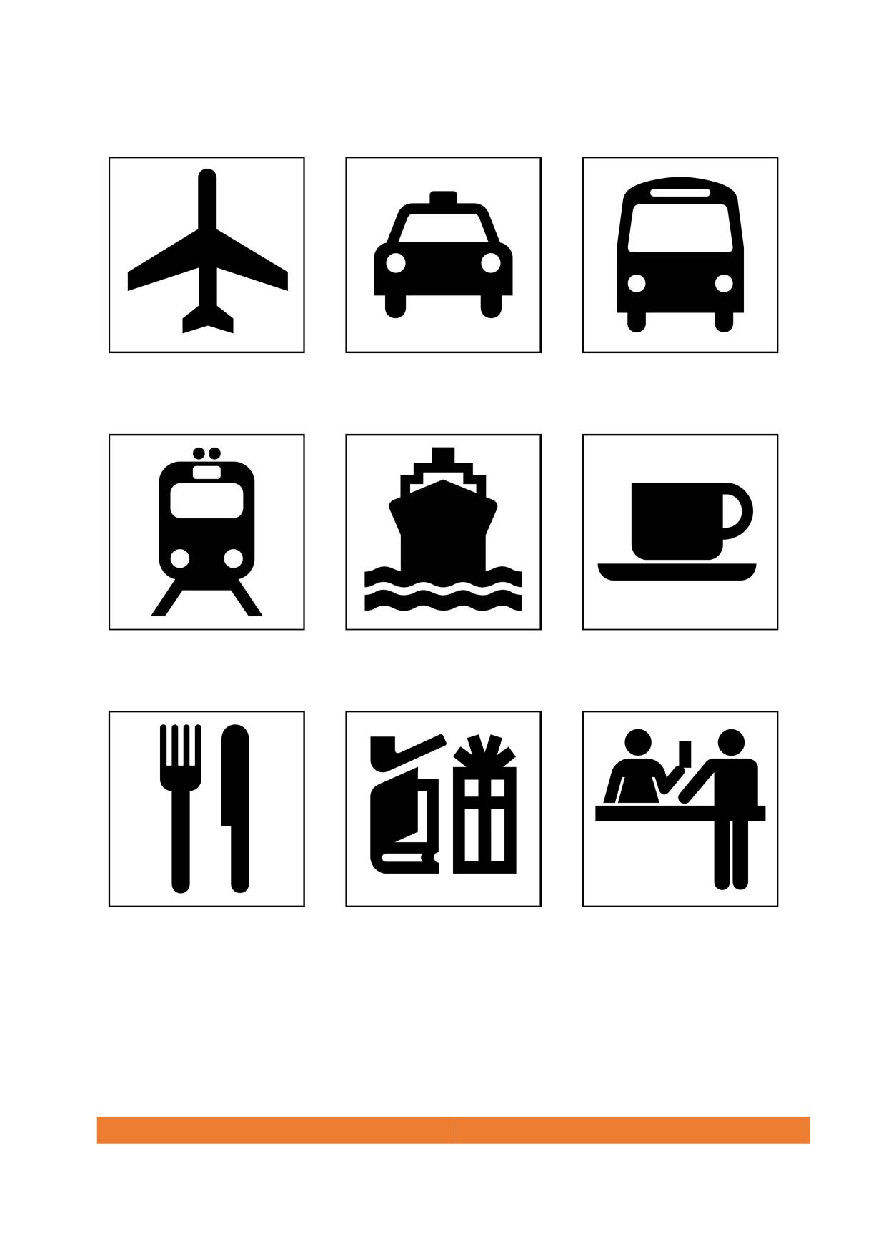
19. Airport
20. Taxi
21. Bus
22. Metro
23. Water transportation
24. Coffee Shop
25. Restaurant
26. Shopping
27. Ticket Purchase
249
14.11.
High embossment
1. Tactile signage should be used, letters, numbers, symbols and pictographs should
be raised at least 0.8 mm and should be between 16 mm and 50 mm high. If a tactile
sign is mounted on a wall, its center should be at a height of 1500 mm ±25 mm
above the floor.
2. Long messages should be avoided for reading of letters and symbols in high
embossment.
3. It should be used for rooms or spaces identification signs. These signs preferably
represent a single icon or character; for example, the number of an elevator floor,
restrooms icon, etc.
4. High embossment letters shall be in upper case.
5. The tactile signs must be in high embossment and not engraved.
6. Symbol height shall not be less than 30 mm. The embossment thickness will be of
between 2 mm and 5 mm for letters and of 2 mm for symbols.
14.12.
Braille
Although a minority of people with visual impairments use Braille, it is a good design
practice to include this form of writing in signage following the criteria of this Code.
250
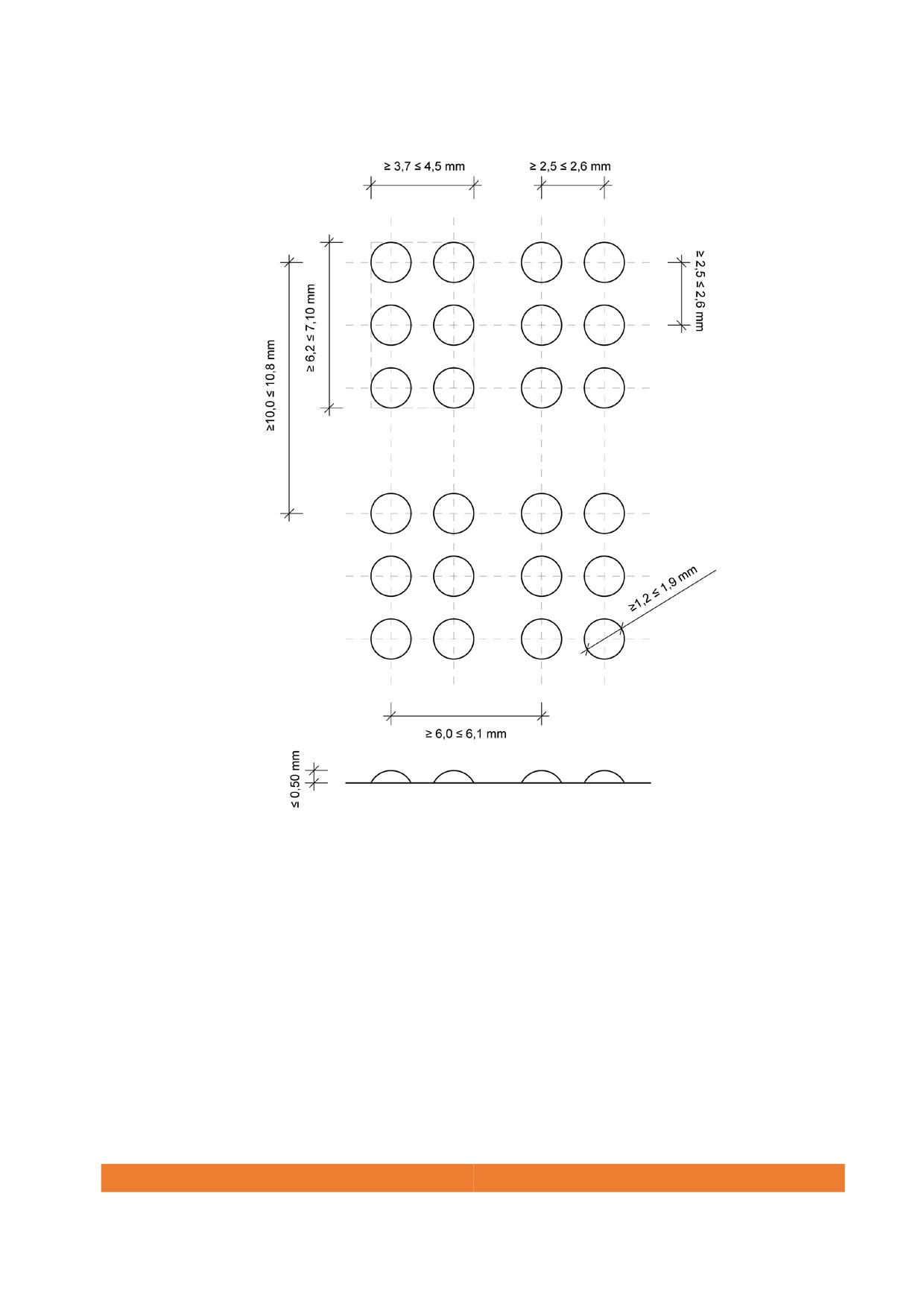
Figure 128. Dimensions of Braille
14.13.
Position
1. Signs shall be mounted out of the accessible path and must not interfere with clear
headroom along the entire path of at least 2200 mm.
2. Place signs in consistent, predictable locations. Standardise the position of the same
family of signs in the same areas of the environment.
3. Signs shall be well illuminated at all times. Lighting and sun should not produce
shadows or glare on the signs. For signs that are illuminated externally by ambient
lighting, the preferred graphics is a dark colour against a light-coloured backg0round.
251
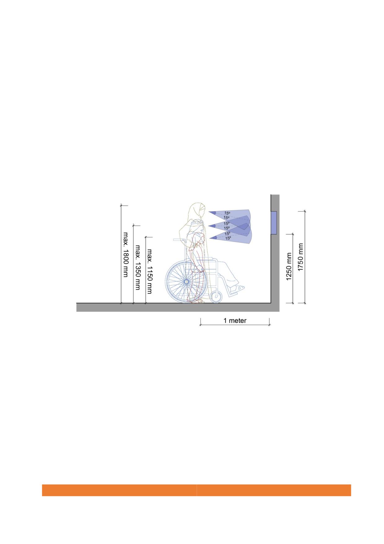
4. Avoid the backg0rounds of signs in strong visual textures or that are reflective.
5. Obstacles between signs and the observers shall be avoided.
6. Signs in walls must be centred at a height of 1600 mm and the upper edge to a
maximum height of 1750 mm above the ground. If mainly children use a space, a
second level shall be installed, placing the second sign at a maximum height of 1250
mm.
7. When the sign is mounted on a horizontal or inclined plane, inclination should be of
between 30º and 45º from the horizontal level.
Figure 129. Vertical visual reach - close distance
252
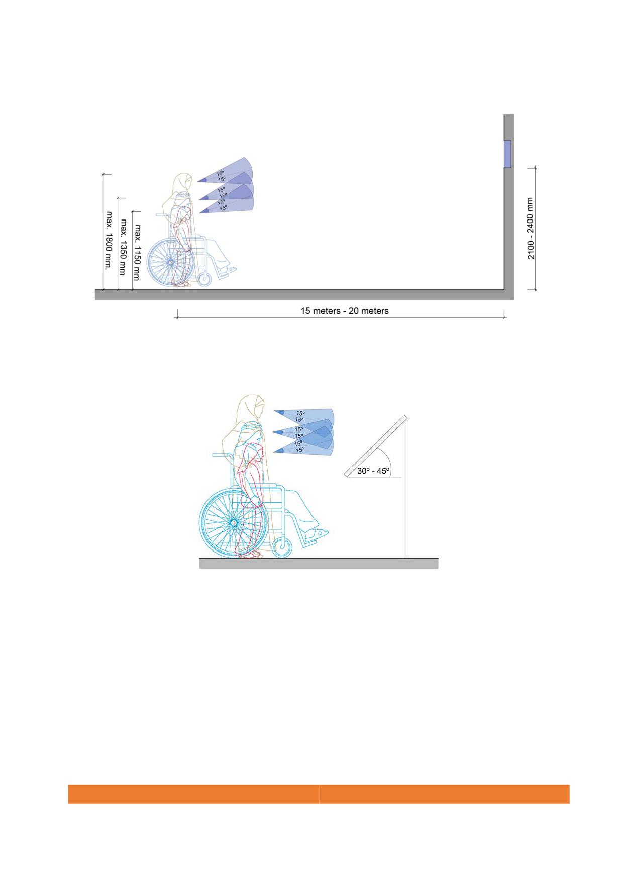
Figure 130. Vertical visual reach - far distance
Figure 131. Inclined sign and tactile maps
8. Directional signs on a long route should be repeated sequentially starting from the
decision-making point/junction, with a maximum spacing of 30 m. They serve as
confirmation signs and repeater signs along the route.
253
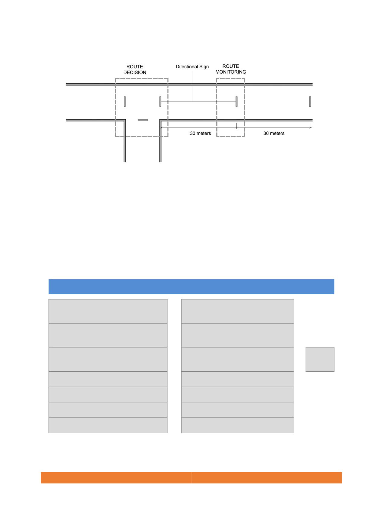
Figure 132. Position of signs during the navigation
14.14.
Combination of communication processes
To ensure an accessible communication process, a combination of different
communication channels must be provided depending on the environment or service.
The communication must include at least two of the three channels of communication:
acoustic, visual and tactile.
A number of possible valid combinations of an accessible communication process are
displayed in the table below:
Combination of communication channels
Alphabetical and symbolic writing
Tactile references / guiding
+
tactile pavement
Alphabetical and symbolic writing
Alphabetical and symbolic
+
embossed writing
Alphabetical and symbolic writing
Alphabetical and symbolic
+
+
Braille
embossed writing
Alphabetical and symbolic writing
+
Oral information
Alphabetical writing
+
Braille
Light signal
+
Simultaneous sound signal
Oral Communication
+
Sign language/written text
Table 15. Accessible communication combinations
254

Annexes
255
Annex 1 - Licensing procedures
14.15.
Accessible path drawings
Building projects shall include a floor plan drawing providing evidence that all
dimensional requirements are fulfilled.
In this drawing the following information shall be clearly illustrated:
• The passage width, doors and manoeuvring dimensions.
• The situation of the building stairs, elevators and toilets.
• The distance between the furthest point from the facilities and the facilities
indicated on the preceding point. This distance shall be drawn on the floor plan
and the distance shall be calculated and written.
14.16.
Way finding drawings
Building projects shall include a floor plan drawing providing evidences of way finding
coherence and continuity.
In this drawing the following information shall be clearly illustrated:
• All directional signs with the text, colours and symbols. Moreover, the signs
location shall be indicated.
• The situation of the building’s main different facilities, including stairs and
elevators, toilets, offices, stores… The directional signs shall be coherent with
the facilities location.
256
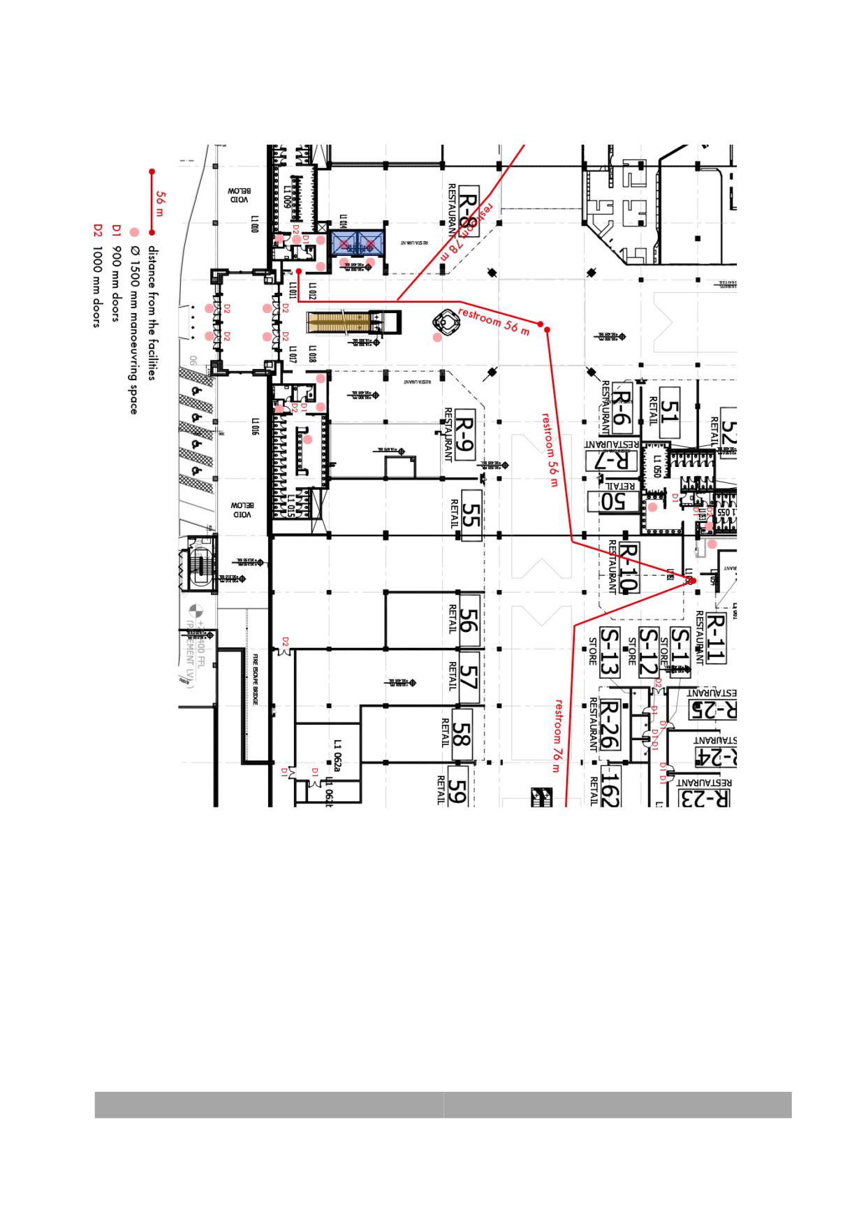
Figure 133. Example of accessible path drawing
257
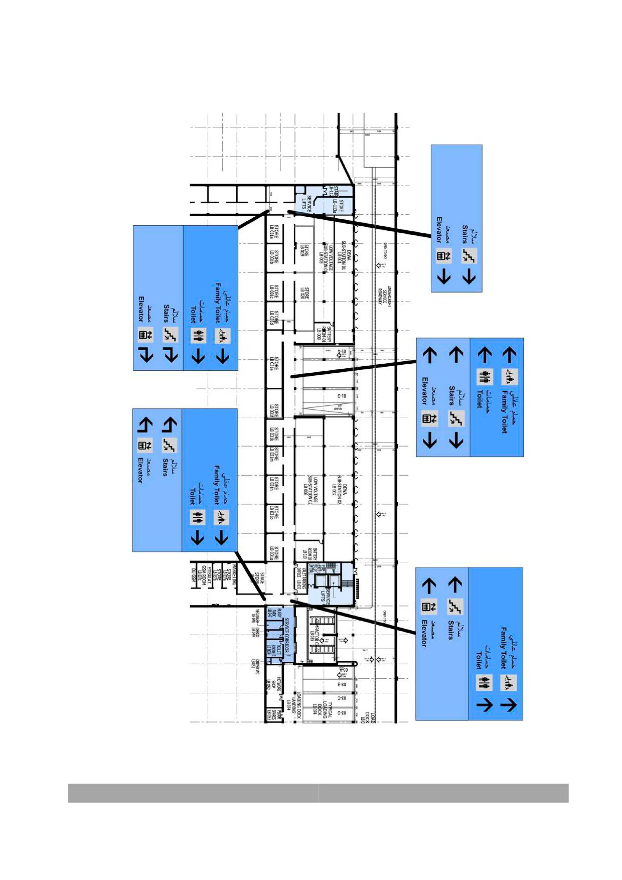
Figure 134. Example of accessible wayfinding drawing
258
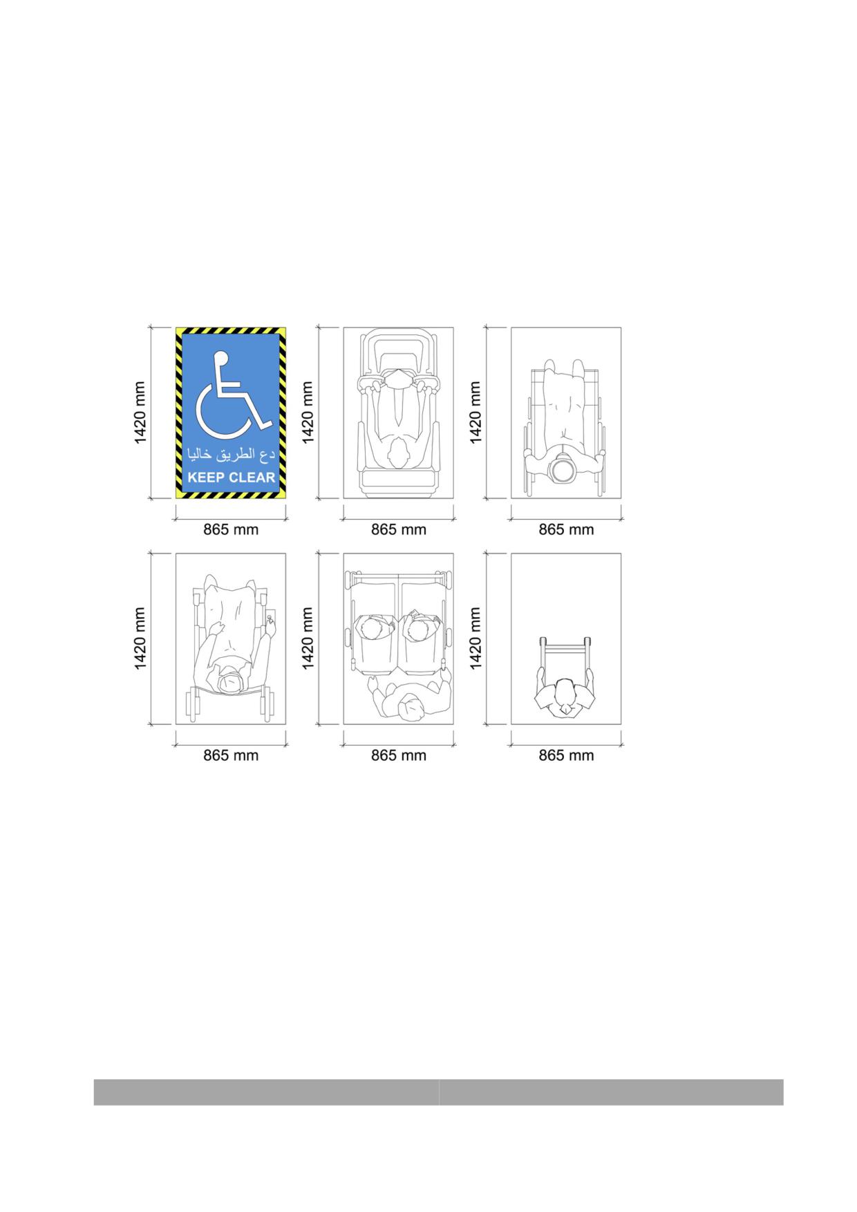
Annex 2 - Anthropometrics
The drawings below present population’s extreme dimensions that are considered for
this Code and certain functional aspects that shall be also considered when designing.
14.17.Interaction area
Figure 135. Extreme horizontal dimensions
259
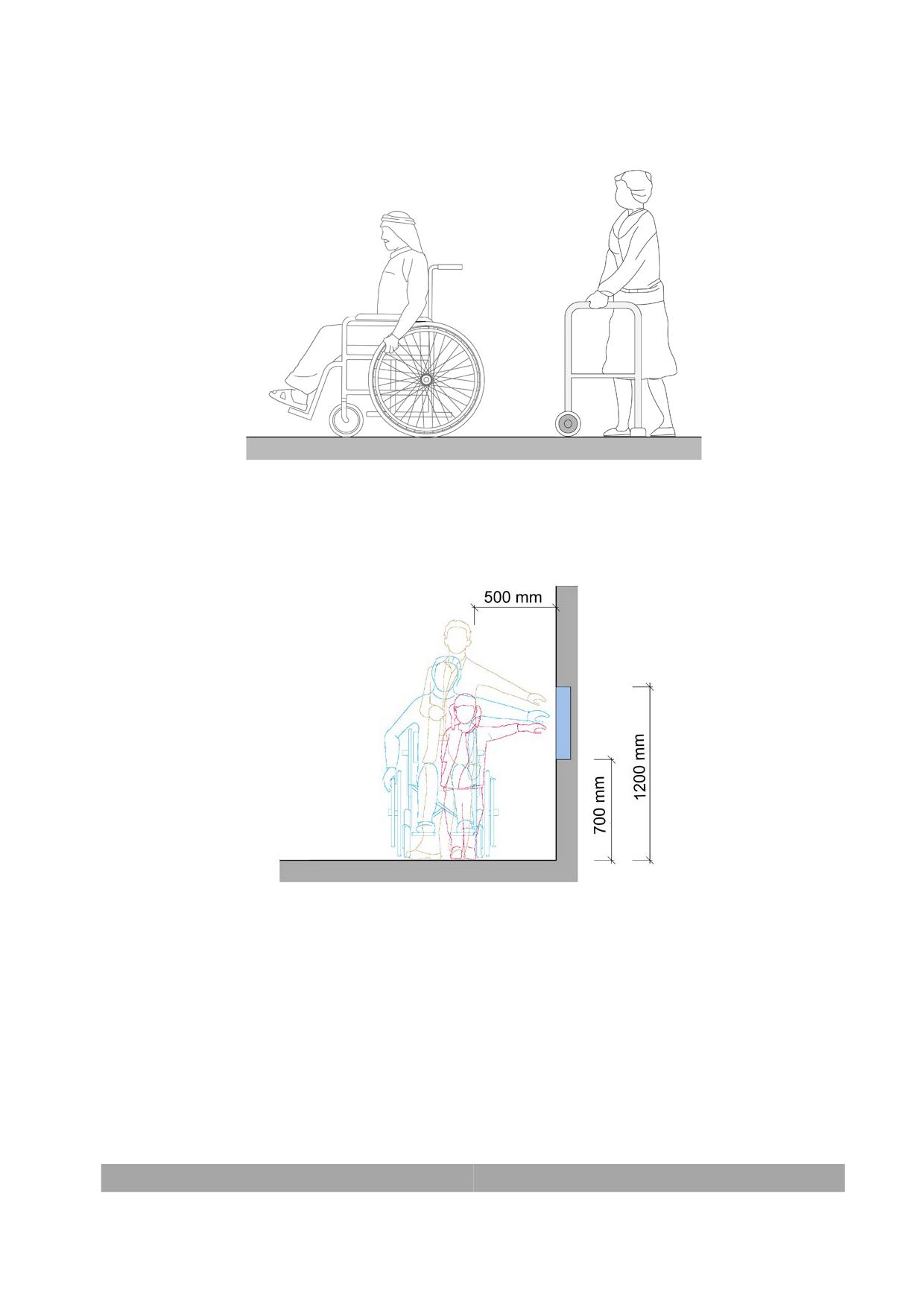
Figure 136. Elevation of a wheelchair and a walker user
14.18.Vertical reach
Figure 137. Vertical reach
260
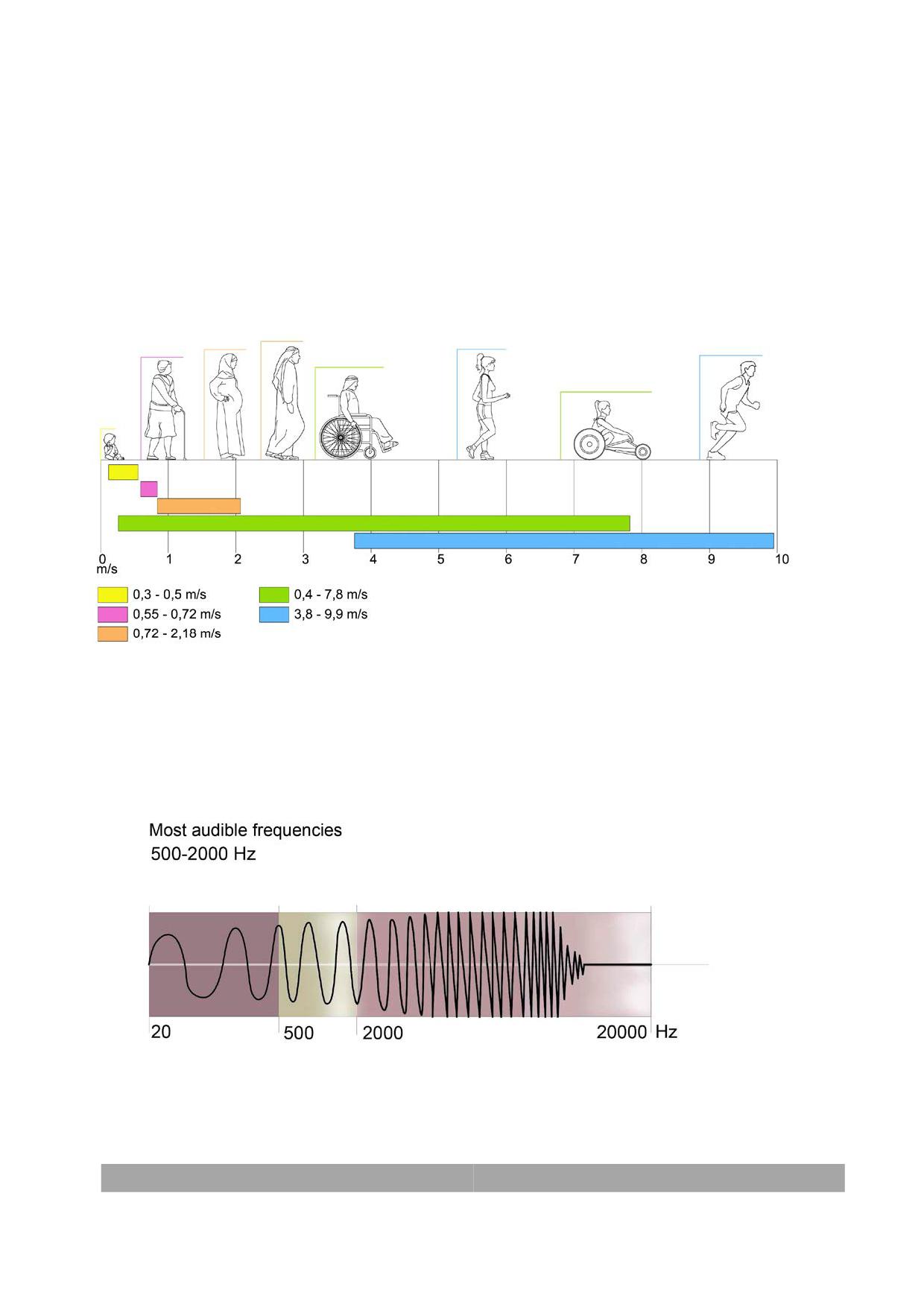
14.19.Walking and running speed
To be aware of walking and running speeds is relevant when designing parks and
streets.
Especially relevant is to consider people walking slowly when defining the green time for
pedestrians in traffic lights.
Figure 138. Usual walking, rolling and running speeds
Audible communication in the range of 500-2.000 Hz should be favoured in acoustic
signals, alarms and voice messages in Public Announcement Systems.
Figure 139. Audible frequencies
261
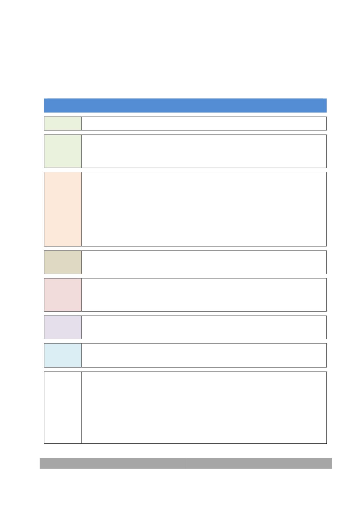
Annex 3 - Required accessibility in each
building type
Legend
UA
Universally Accessible
UA*
When the building is built in a floodable zone the entrances of the
building can have a change in level from the exterior floor level. In this
exceptional case the entrances solutions may be permitted.
UA/P
Only for small new and existing buildings: paths can be smaller
respecting the Tolerance Limits and is permitted interaction space only in
one side in the toilet.
Only for retrofitting existing buildings: The building facility shall be
Universally Accessible; however, if the Universal Accessibility level is
technically or economically impossible exceptions can be accepted
respecting the Tolerance Limits.
C
Convertible. Presents dimensions that allow transform the house or
apartment to reach at least the Permissible level in a future at a low cost.
UA/PM
The facility shall follow the Paralympics Committee requirements as long
as these requirements are greater than the Dubai Universal Accessibility
Code requirements. If not the facility shall be Universally Accessible.
TA/FT
Tactile maps are required and accessible toilets outside toilets blocks are
not accepted as family toilets.
FT/F
Additional to the Universal Accessible toilets a Family toilet and a feeding
room are requested.
All*
All industrial buildings and laboratories areas except:
- The ones that handle oil and gas, refinery industry, chemicals, toxic
materials and potential explosive compounds.
- Areas with activities that require a “gowning regime”.
- Production areas with heavy machinery.
- Areas for warehousing and storage.
262
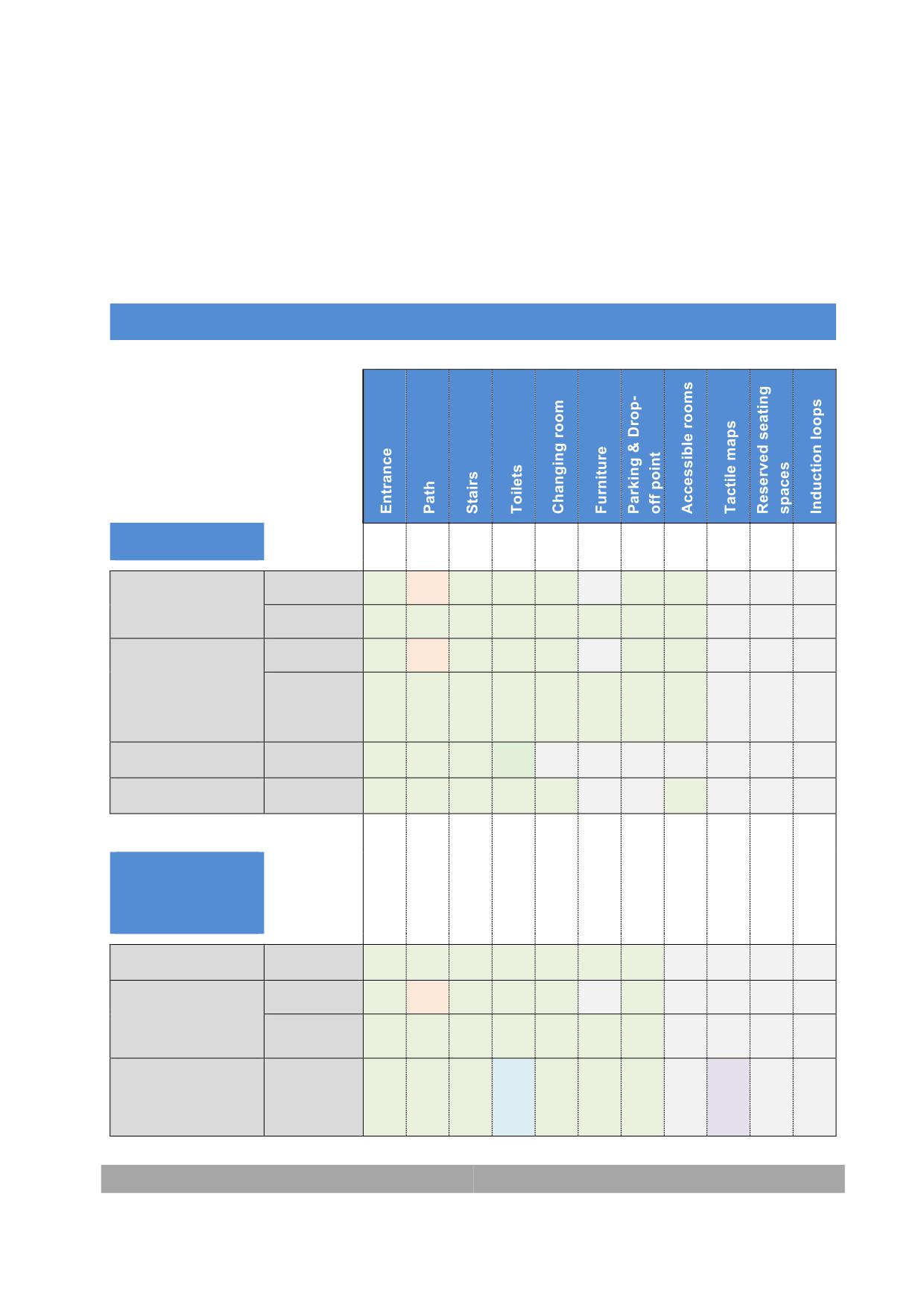
14.20.
Required accessibility provisions for new buildings
For buildings and facilities built with a permit to build issued after the date of entry into
force of the Code and for any modification, extension or change of use project the
following table applies.
MINIMUM LEVELS OF ACCESSIBILITY FOR NEW BUILDINGS
Hotels
Hotels & motels
≤ 50 beds
UA*
UA/P
UA
UA
UA
UA
UA
> 50 beds
UA*
UA
UA
UA
UA
UA
UA
UA
Students
≤ 50 seats
UA*
UA/P
UA
UA
UA
UA
UA
residences in
> 50 seats
educational
UA*
UA
UA
UA
UA
UA
UA
UA
buildings
Labour camps
All
UA*
UA
UA
UA
Prisons
All
UA*
UA
UA
UA
UA
UA
Commercial,
restaurants and
cafeterias
Markets
All
UA*
UA
UA
UA
UA
UA
UA
Shops, bank
≤ 500 m2
UA*
UA/P
UA
UA
UA
UA
offices, beauty
> 500 m2
UA*
UA
UA
UA
UA
UA
UA
salons and similar
Commercial
All
centres >10.000
UA*
UA
UA
FT/F
UA
UA
UA
TA/FT
m2
263
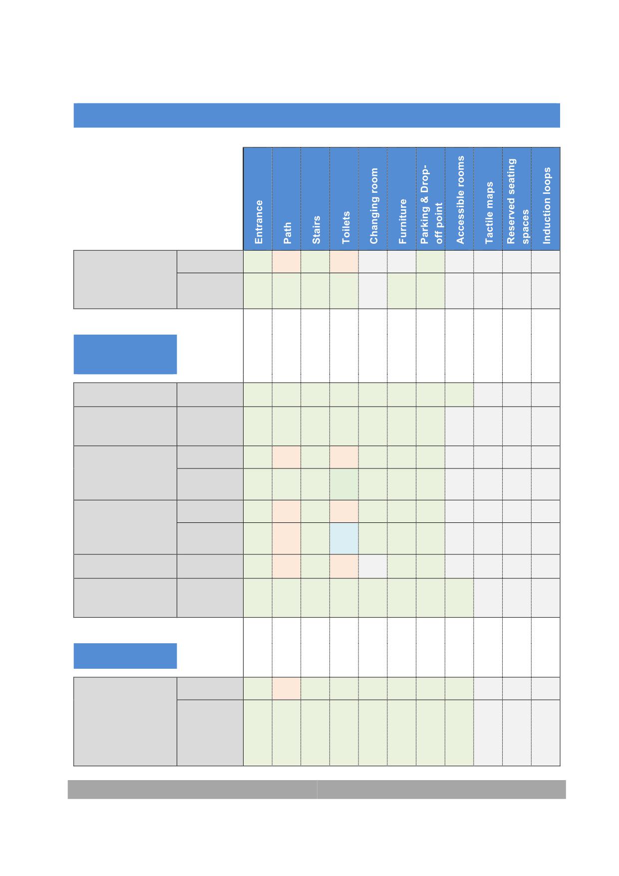
MINIMUM LEVELS OF ACCESSIBILITY FOR NEW BUILDINGS
Cafes and
≤ 50 seats
UA*
UA/P
UA
UA/P
UA
Restaurants
> 50 seats
UA*
UA
UA
UA
UA
UA
Healthcare
facilities
Hospitals & Clinics
All
UA*
UA
UA
UA
UA
UA
UA
UA
Ambulatory health
All
UA*
UA
UA
UA
UA
UA
UA
centres
Doctors’ private
≤100 m2
UA*
UA/P
UA
UA/P
UA
UA
UA
offices and dental
> 100 m2
UA*
UA
UA
UA
UA
UA
UA
clinics
Health services:
≤ 1000 m2
UA*
UA/P
UA
UA/P
UA
UA
UA
optics,
> 1000 m2
UA*
UA/P
UA
FT/F
UA
UA
UA
orthopaedics...
Pharmacy
All
UA*
UA/P
UA
UA/P
UA
UA
Social-health
All
UA*
UA
UA
UA
UA
UA
UA
UA
centres
Social
Residential and
≤ 25 seats
UA*
UA/P
UA
UA
UA
UA
UA
UA
day centres for the
> 25 seats
elderly and people
UA*
UA
UA
UA
UA
UA
UA
UA
with disability
264
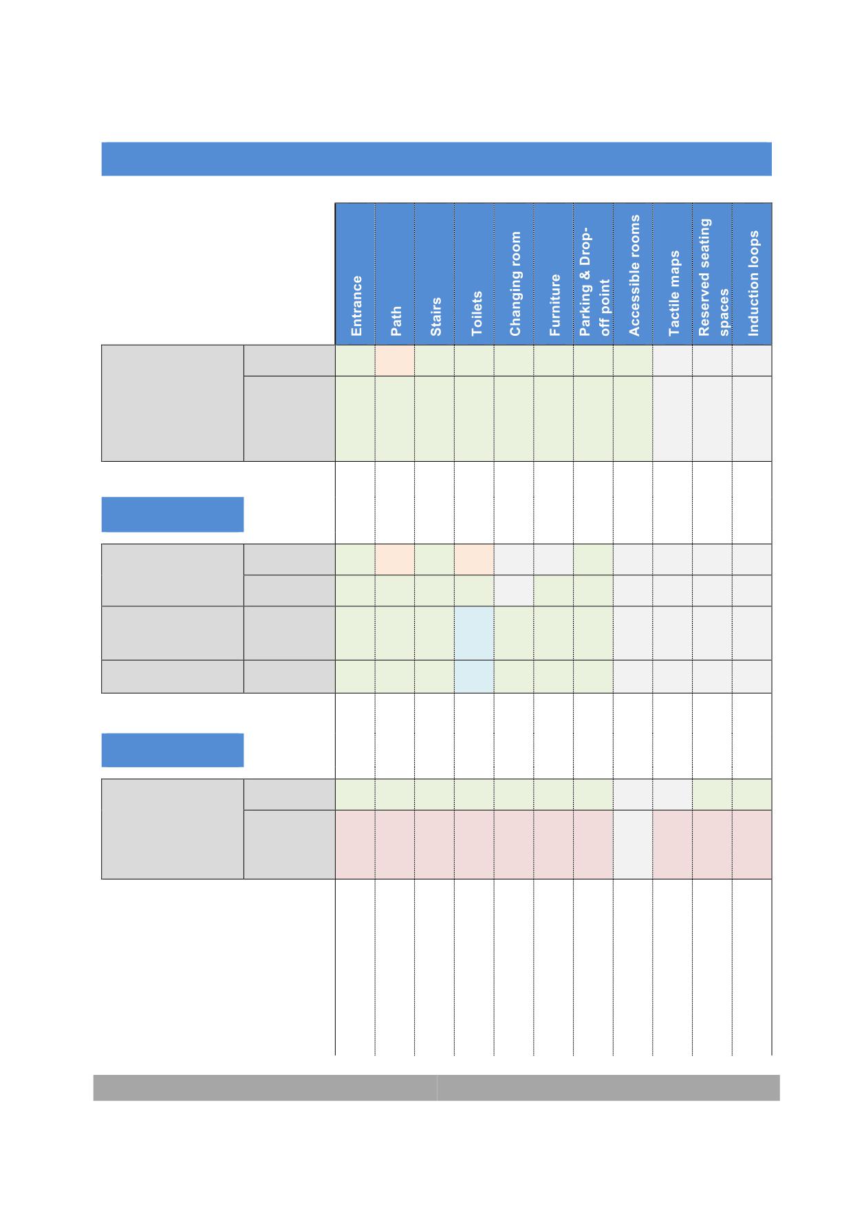
MINIMUM LEVELS OF ACCESSIBILITY FOR NEW BUILDINGS
Other residential
≤ 25 seats
UA*
UA/P
UA
UA
UA
UA
UA
UA
and day centres,
> 25 seats
therapeutic
UA*
UA
UA
UA
UA
UA
UA
UA
communities,
assisted homes
Recreation
Function halls
≤ 50 seats
UA*
UA/P
UA
UA/P
UA
> 50 seats
UA*
UA
UA
UA
UA
UA
Amusement parks
All
UA*
UA
UA
FT/F
UA
UA
UA
and theme parks
Leisure centres
All
UA*
UA
UA
FT/F
UA
UA
UA
Sport facilities
Sport centers
All
UA*
UA
UA
UA
UA
UA
UA
UA
UA
For
UA/
UA/
UA/
UA/
UA/
UA/
UA/
UA/
UA/
UA/
international
PC
PC
PC
PC
PC
PC
PC
PC
PC
PC
competitions
265
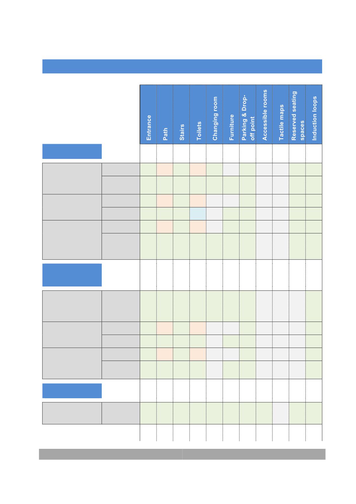
MINIMUM LEVELS OF ACCESSIBILITY FOR NEW BUILDINGS
Cultural
Libraries, civic
≤ 100 m2
UA*
UA/P
UA
UA/P
UA
UA
UA
UA
centers and
> 100 m2
UA*
UA
UA
UA
UA
UA
UA
UA
UA
exhibition rooms
Museums
≤ 1000 m2
UA*
UA/P
UA
UA/P
UA
UA
UA
> 1000 m2
UA*
UA
UA
FT/F
UA
UA
UA
UA
Theatres,
≤ 50 seats
UA*
UA/P
UA
UA/P
UA
UA
UA
UA
cinemas,
> 50 seats
conference rooms
UA*
UA
UA
UA
UA
UA
UA
UA
UA
and auditoriums
Public
Administration
Public
All
administration
UA*
UA
UA
UA
UA
UA
UA
UA
buildings
Public utilities
≤ 100 m2
UA*
UA/P
UA
UA/P
UA
UA
companies offices
> 100 m2
UA*
UA
UA
UA
UA
UA
UA
Public offices and
≤ 500 m2
UA*
UA/P
UA
UA/P
UA
UA
professional
> 500 m2
UA*
UA
UA
UA
UA
UA
UA
offices
Education
Educational
All
UA*
UA
UA
UA
UA
UA
UA
UA
UA
UA
buildings
266
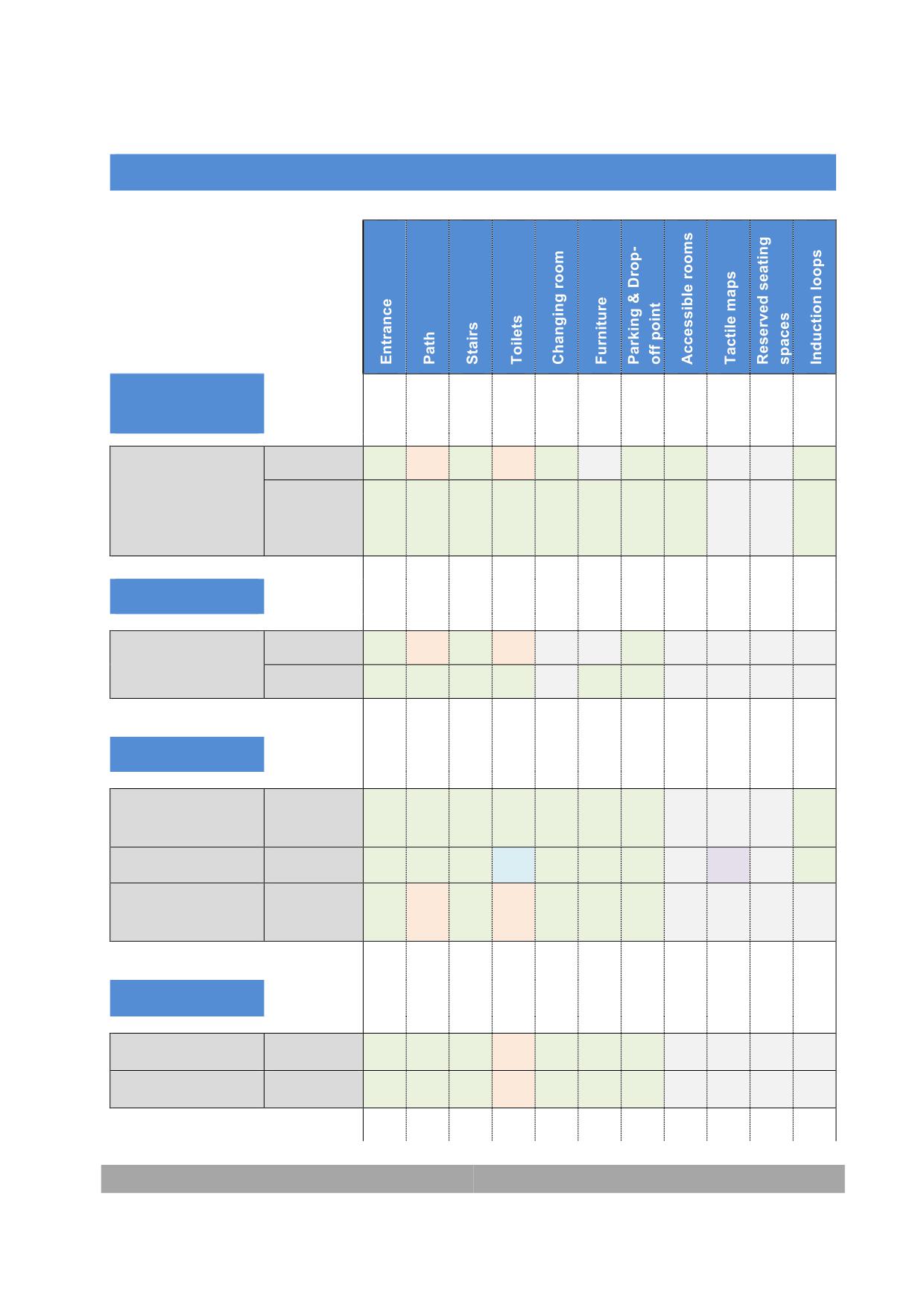
MINIMUM LEVELS OF ACCESSIBILITY FOR NEW BUILDINGS
Religious
facilities
Mosques and
≤ 50 seats
UA*
UA/P
UA
UA/P
UA
UA
UA
UA
other religious
> 50 seats
buildings
UA*
UA
UA
UA
UA
UA
UA
UA
UA
Parking
Garage and
≤ 50 spots
UA*
UA/P
UA
UA/P
UA
parking
> 50 spots
UA*
UA
UA
UA
UA
UA
Transportation
Rail transport
All
UA*
UA
UA
UA
UA
UA
UA
UA
station
Airports
All
UA*
UA
UA
FT/F
UA
UA
UA
TA/FT
UA
Service areas and
All
UA*
UA/P
UA
UA/P
UA
UA
UA
petrol stations
Other uses
All*
UA
UA
UA/P
UA
UA
UA
Industrial
UA*
All*
UA
UA
UA/P
UA
UA
UA
Laboratories
UA*
267
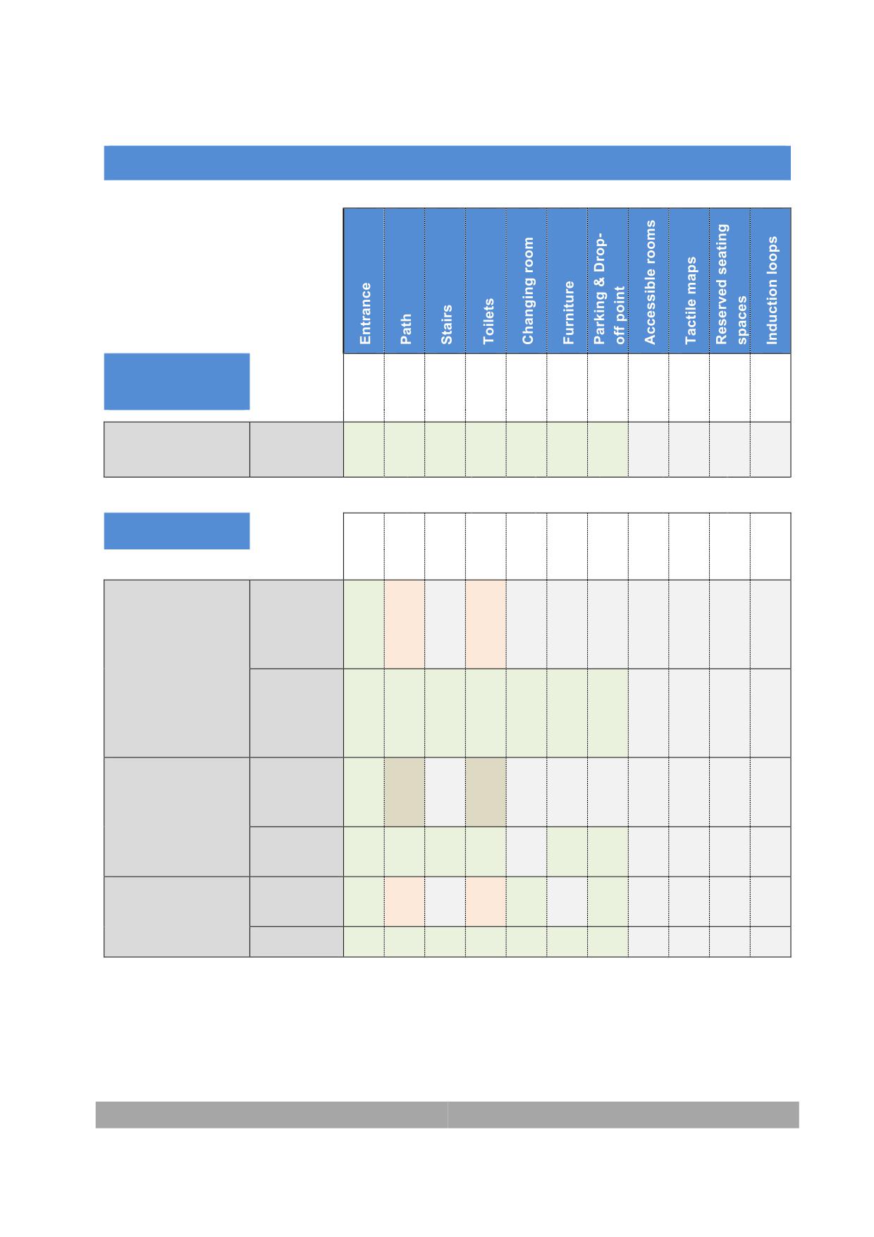
MINIMUM LEVELS OF ACCESSIBILITY FOR NEW BUILDINGS
Undefined use
buildings
Undefined use
All
UA*
UA
UA
UA
UA
UA
UA
buildings
Residential
Common
Without
circulation areas
universally
UA*
UA/P
UA/P
accessible
housing
With
universally
UA*
UA
UA
UA
UA
UA
UA
accessible
housing
Inside housing
Non
universally
UA*
C
C
accessible
Universally
UA*
UA
UA
UA
UA
UA
accessible
Other common
500 to 1000
UA*
UA/P
UA/P
UA
UA
areas
m2
> 1000 m2
UA*
UA
UA
UA
UA
UA
UA
268
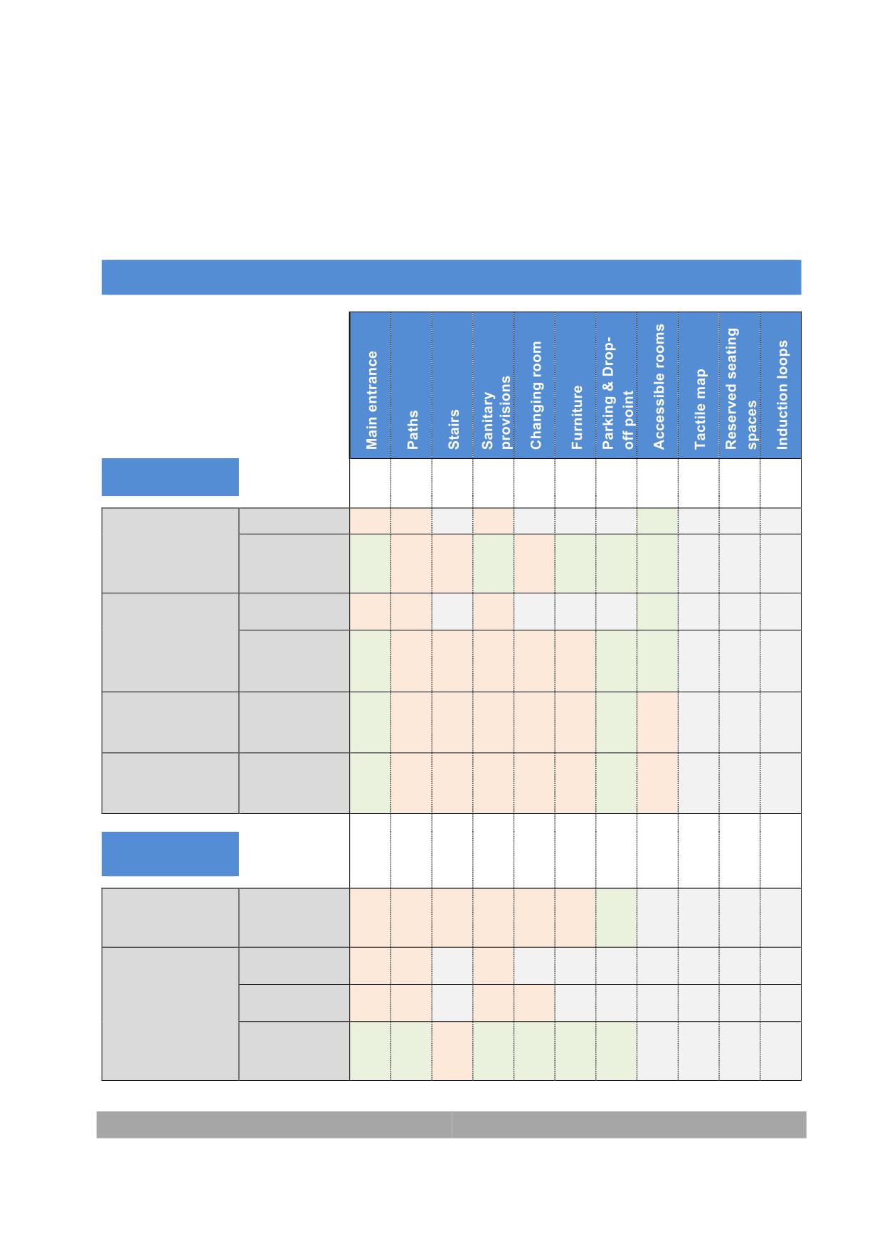
14.21.
Required accessibility provisions for existing buildings
For buildings and facilities built with a permit to build issued before the date of entry into
force of the Code the following table applies.
MINIMUM LEVELS OF ACCESSIBILITY FOR EXISTING BUILDINGS
Residential
Hotels & motels
≤ 50 beds
UA/P
UA/P
UA/P
UA
> 50 beds
UA*
UA/P
UA/P
UA
UA/P
UA
UA
UA
Students
≤ 50 seats
UA/P
UA/P
UA/P
UA
residences in
educational
> 50 seats
UA*
UA/P
UA/P
UA/P
UA/P
UA/P
UA
UA
buildings
Labour camps
All
UA*
UA/P
UA/P
UA/P
UA/P
UA/P
UA
UA/P
UA*
UA
UA
UA
UA
UA
Prisons
All
Commercial
Markets
All
UA/P
UA/P
UA/P
UA/P
UA/P
UA/P
UA
Shops, bank
≤ 100 m2
UA/P
UA/P
UA/P
offices, beauty
100 to 500 m2
UA/P
UA/P
UA/P
UA/P
salons and
similar
> 500 m2
UA*
UA
UA/P
UA
UA
UA
UA
269
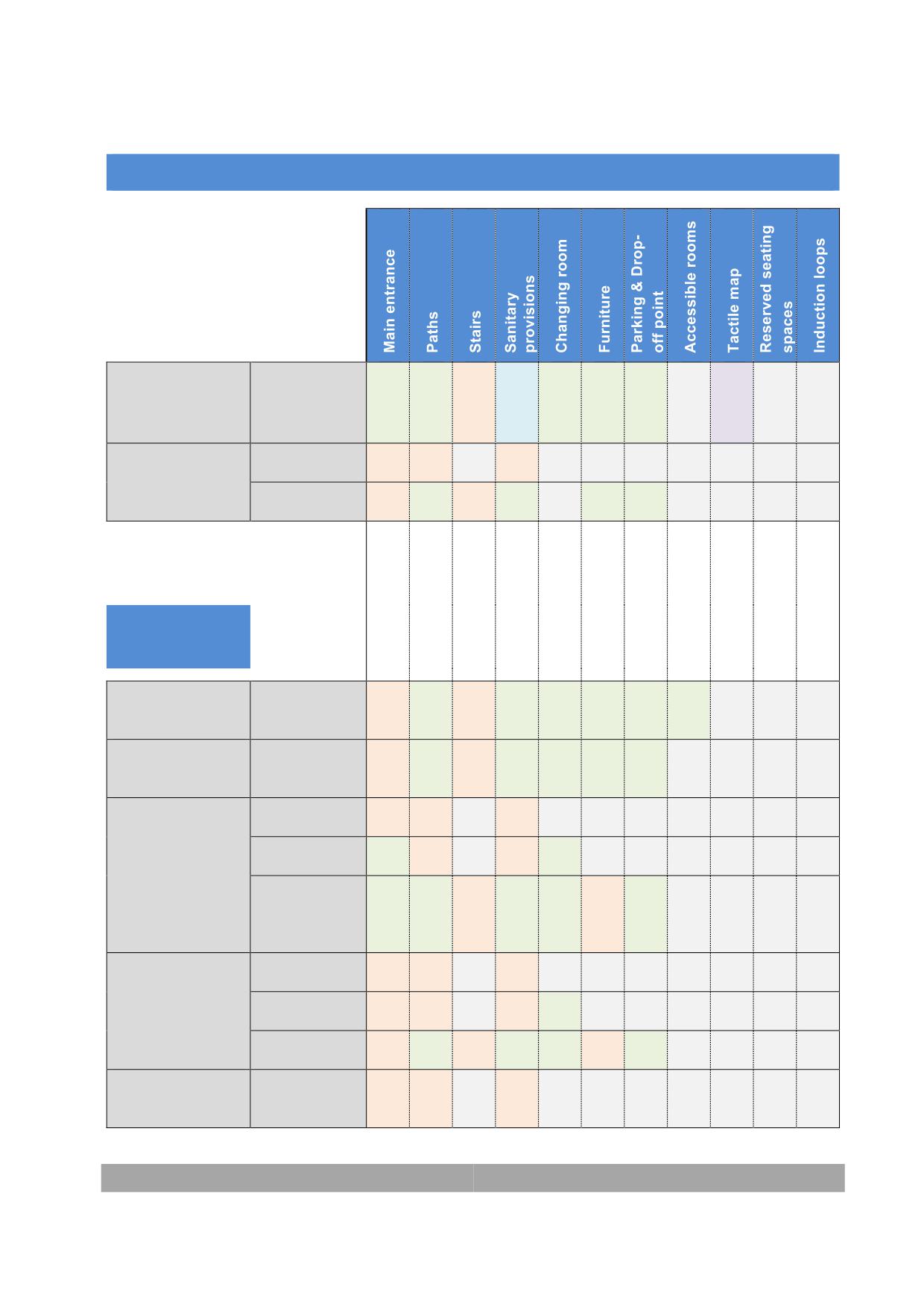
MINIMUM LEVELS OF ACCESSIBILITY FOR EXISTING BUILDINGS
Commercial
All
centres > 10.000
UA*
UA
UA/P
FT/F
UA
UA
UA
TA/FT
m2
Cafes and
≤ 100 seats
UA/P
UA/P
UA/P
Restaurants
> 100 seats
UA/P
UA
UA/P
UA
UA
UA
Healthcare
facilities
Hospitals &
All
UA/P
UA
UA/P
UA
UA
UA
UA
UA
Clinics
Ambulatory
All
UA/P
UA
UA/P
UA
UA
UA
UA
health centres
Doctors’ private
≤ 100 m2
UA/P
UA/P
UA/P
offices and
100 to 500 m2
UA/P
UA/P
UA/P
UA
dental clinics
Health services:
> 500 m2
optics,
UA/P
UA
UA/P
UA
UA
UA/P
UA
orthopaedics...
≤ 100 m2
UA/P
UA/P
UA/P
Health services:
optics,
100 to 500 m2
UA/P
UA/P
UA/P
UA
orthopaedics...
> 500 m2
UA/P
UA
UA/P
UA
UA
UA/P
UA
Pharmacy
Hospitals &
All
UA/P
UA/P
UA/P
Clinics
270
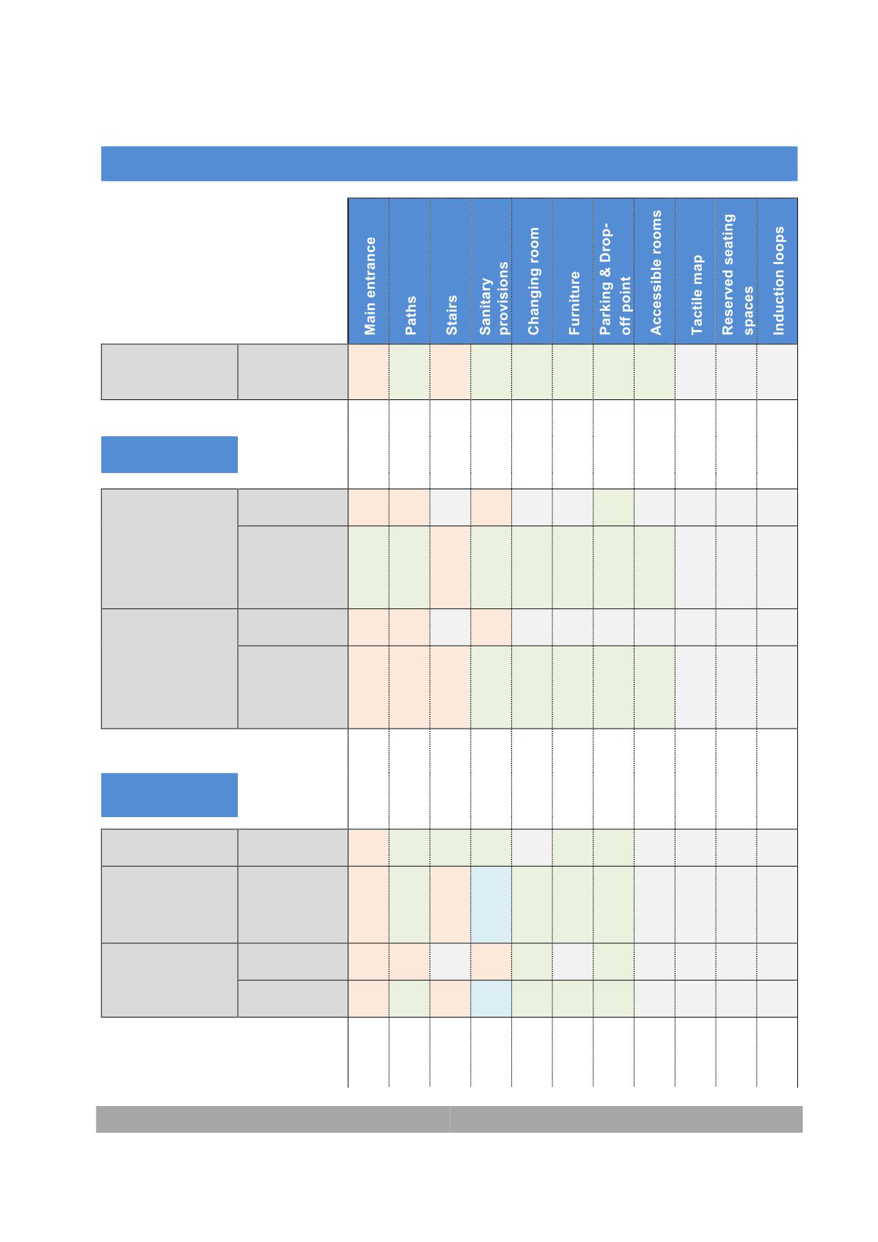
MINIMUM LEVELS OF ACCESSIBILITY FOR EXISTING BUILDINGS
Ambulatory
All
UA/P
UA
UA/P
UA
UA
UA
UA
UA
health centres
Social
Residential and
≤ 25 seats
UA/P
UA/P
UA/P
UA
day centres for
> 25 seats
the elderly and
UA*
UA
UA/P
UA
UA
UA
UA
UA
people with
disability
Other residential
25 to 50 seats
UA/P
UA/P
UA/P
and day centres,
> 50 seats
therapeutic
communities,
UA/P
UA/P
UA/P
UA
UA
UA
UA
UA
assisted homes
Recreation
Function Halls
> 50 seats
UA/P
UA
UA
UA
UA
UA
Amusement
All
parks and theme
UA/P
UA
UA/P
FT/F
UA
UA
UA
parks
Leisure centres
≤ 500 m2
UA/P
UA/P
UA/P
UA
> 500 m2
UA/P
UA
UA/P
FT/F
UA
UA
UA
271
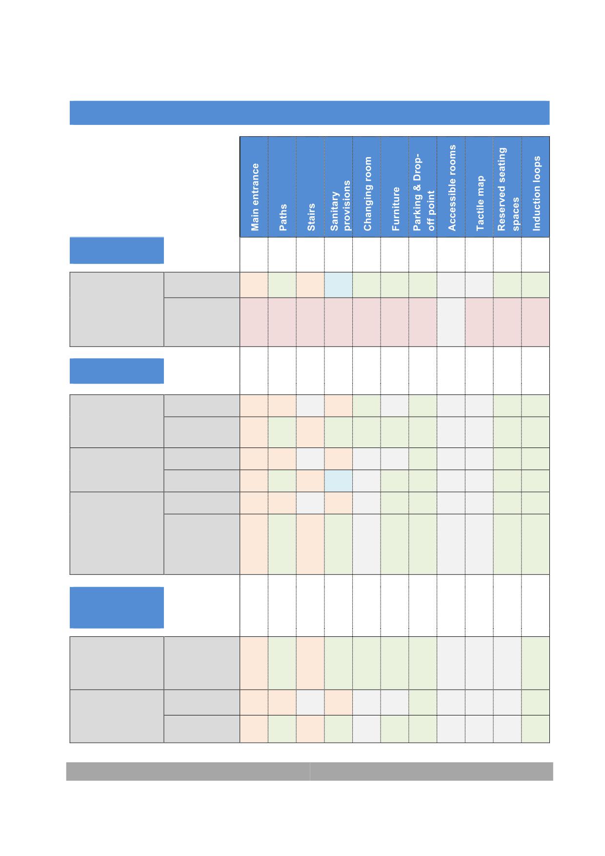
MINIMUM LEVELS OF ACCESSIBILITY FOR EXISTING BUILDINGS
Sport facilities
Sport centres
All
UA/P
UA
UA/P
FT/F
UA
UA
UA
UA
UA
For
UA/
UA/
UA/
UA/
UA/
UA/
UA/
UA/
UA/
UA/
international
PC
PC
PC
PC
PC
PC
PC
PC
PC
PC
competitions
Cultural
Libraries, civic
≤ 200 m2
UA/P
UA/P
UA/P
UA
UA
UA
centres and
> 200 m2
UA/P
UA
UA/P
UA
UA
UA
UA
UA
exhibition rooms
Museums
≤ 200 m2
UA/P
UA/P
UA/P
UA
UA
> 200 m2
UA/P
UA
UA/P
FT/F
UA
UA
UA
UA
Theatres,
≤ 50 seats
UA/P
UA/P
UA/P
UA
UA
UA
cinemas,
> 50 seats
conference
UA/P
UA
UA/P
UA
UA
UA
UA
UA
rooms and
auditoriums
Public
Administration
Public
All
administration
UA/P
UA
UA/P
UA
UA
UA
UA
UA
buildings
Public utilities
≤ 200 m2
UA/P
UA/P
UA/P
UA
UA
companies
> 200 m2
UA/P
UA
UA/P
UA
UA
UA
UA
offices
272
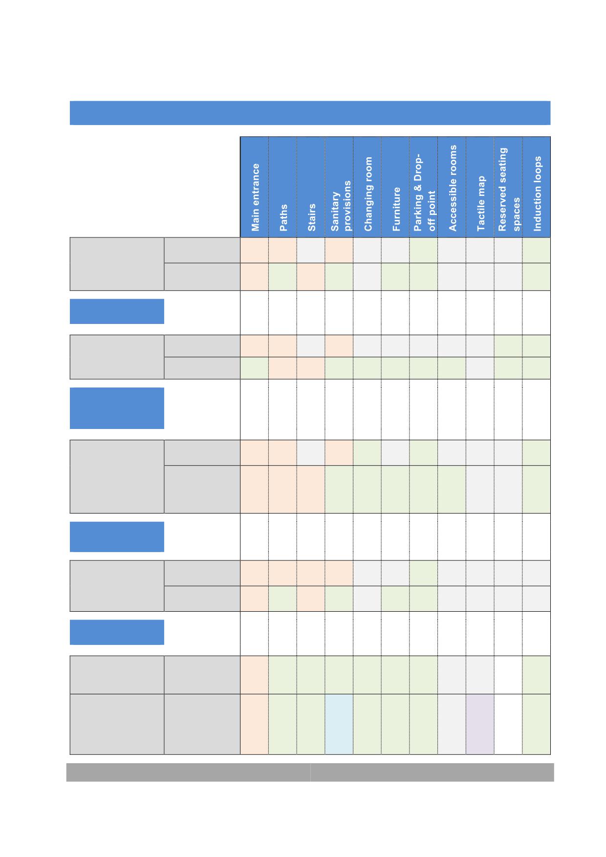
MINIMUM LEVELS OF ACCESSIBILITY FOR EXISTING BUILDINGS
Public offices
≤ 500 m2
UA/P
UA/P
UA/P
UA
UA
and professional
> 500 m2
UA/P
UA
UA/P
UA
UA
UA
UA
offices
Education
Educational
100 to 500 m2
UA/P
UA/P
UA/P
UA
UA
buildings
> 500 m2
UA*
UA/P
UA/P
UA
UA
UA
UA
UA
UA
UA
Religious
facilities
Mosques & other
≤ 50 seats
UA/P
UA/P
UA/P
UA
UA
UA
Religious
> 50 seats
buildings
UA/P
UA/P
UA/P
UA
UA
UA
UA
UA
UA
Parking
Garage and
10 to 70 spots
UA/P
UA/P
UA/P
UA/P
UA
parking
> 70 spots
UA/P
UA
UA/P
UA
UA
UA
Transport
Rail transport
All
UA/P
UA
UA
UA
UA
UA
UA
UA
station
Airports
All
UA/P
UA
UA
FT/F
UA
UA
UA
TA/FT
UA
273
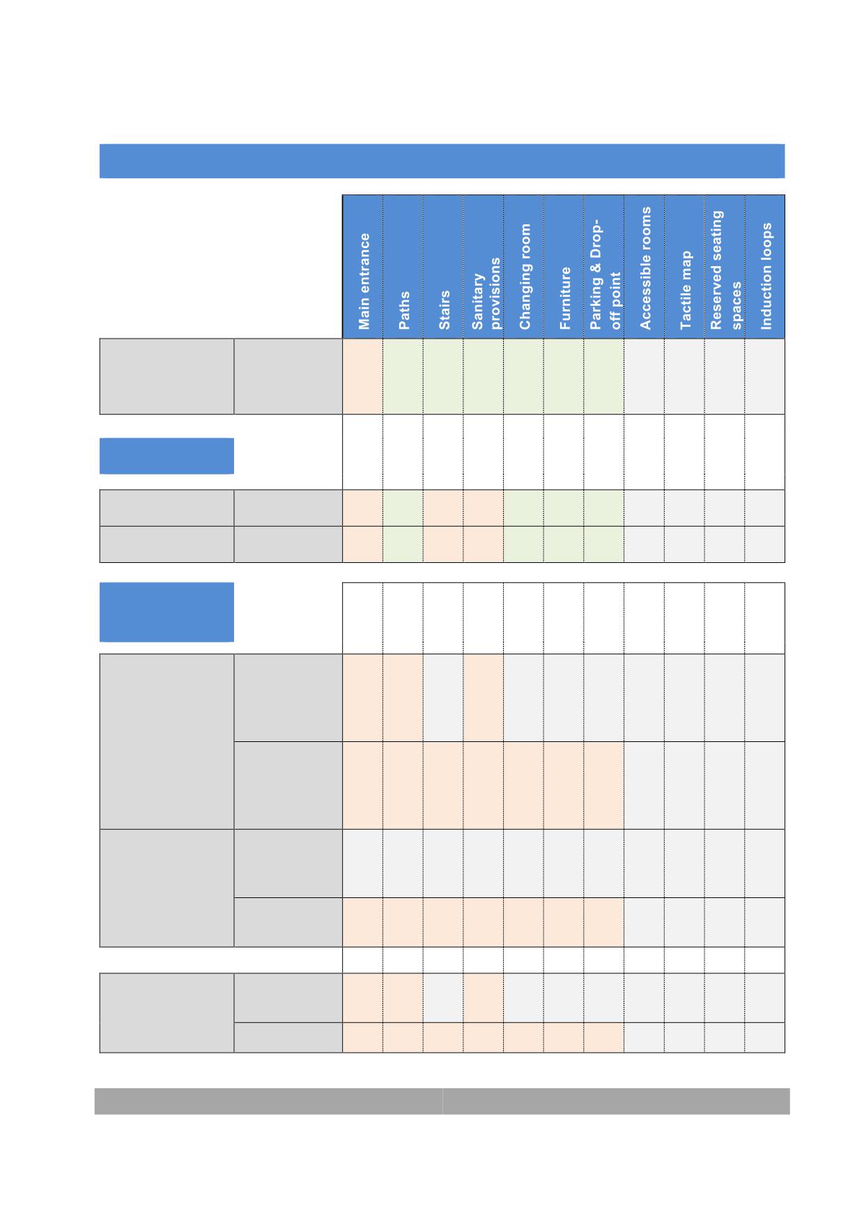
MINIMUM LEVELS OF ACCESSIBILITY FOR EXISTING BUILDINGS
Service areas
All
and petrol
UA/P
UA
UA
UA
UA
UA
UA
stations
Other uses
All*
UA/P
UA
UA/P
UA/P
UA
UA
UA
Industries
All*
UA/P
UA
UA/P
UA/P
UA
UA
UA
Laboratories
Residential
private
Common areas
Without
in residential
universally
UA/P
UA/P
UA/P
accessible
buildings
housing
With
universally
UA/P
UA/P
UA/P
UA/P
UA/P
UA/P
UA/P
accessible
housing
Inside housing
Non
universally
accessible
Universally
UA/P
UA/P
UA/P
UA/P
UA/P
UA/P
UA/P
accessible
Others (except
500 to 1000
UA/P
UA/P
UA/P
restricted use)
m2
> 1000 m2
UA/P
UA/P
UA/P
UA/P
UA/P
UA/P
UA/P
274

Accessibility Checklist
275
15. Accessibility checklist
Accessibility Checklist Rating
Do not accept the project if any of the tick box is empty
To be
filled by
inspector
1. YES answered to all applicable questions
█
2. Accessible path drawing attached
█
3. Wayfinding drawing attached
█
276
Accessible path of travel
Facility/Building …………………………….
Sheet Number ………
Space/Floor …………………….…………..
Observations
Enough width - more than 2000 mm and
with no obstacle reducing it to less than
1200 mm.
Linear and continued
Intersections clearly visible with signs
or lights
Gradient ≤ 5%
Clear headroom ≥ 2200 mm
Absence of uneven surfaces -
irregularities ≤ 5 mm
Absence of protruding objects - No
object protruding into the pedestrian path
more than 100 mm and furniture comply
detection cone rule.
Illumination level ≥ 10 lux
No drain grids on accessible path or
accessible crossings
Free of obstacles and located between
the building’s façade and the furniture
zone
Parking entrance do not modify the
slope or width of the accessible path
Curb height between 100 mm and 150
mm
Cross slope gradient ≤ 2%
277

Accessible path of travel
Facility/Building…………………………….
Sheet Number ………
Space/Floor …………………….…………..
Observations
Pedestrian bridges with ramps or
elevators
278
Floor surfaces
Facility/Building …………………………….
Sheet Number ………
Space/Floor …………………….…………..
Observations
Slip resistance (PTV) comply:
- Level and inclined with ≤ 5%
dry areas indoor - Between 15
and 35
- Inclined < 5% dry areas indoor
≥ 35
- Level and inclined with ≤ 5%
wet areas and outdoor -
Between 35 and 45
- Inclined < 5% wet areas and
outdoor ≥ 45
- Street pavement, swimming
pools and showers ≥ 45
Ground pavement without loose
elements
Rugs and carpets are firmly fixed and
do not increase the strength required
to roll over a ceramic pavement by ≥
25%
Without rounded edges and excessive
joints
Not producing glare
With reflectance contrast of at least 30
points LRV
Lighting in floor not produces glare
and excessive heat
279
Floor surfaces
Facility/Building…………………………….
Sheet Number ………
Space/Floor …………………….…………..
Observations
Absence of utility covers on the path
or with height less of 5 mm
Absence of drain grids on the path or
with holes smaller than 15 mm
Change in level ≤ 5 mm with ≤ 25%
gradient slope
Longitudinal grate openings with
perpendicular orientation to the
pedestrians’ direction of travel
For distance between lower edge of a
tree and the façade ≤ 2000 mm, tree
grate with walkable surface
280
Level changes
Facility/Building …………………………….
Sheet Number ………
Space/Floor …………………….…………..
Observations
Guardrails
Absence of unprotected level changes
- guardrails for heights ≥ 500 mm
Height ≥ 1100 mm
With sufficient strength and stiffness
to withstand a force of 3 kN/m
No climbable
Openings ≤ 100 mm
With a continuous base ≥ 100 mm
Ramps
Only when a change in level with
gradients ≤ 5% are not possible
Gradients slope ≤ 8%
Cross fall gradient ≥ 2%
Run length ≤ 10 meters
Run width 1000 mm between handrails
No curved ramps
Landings at the beginning and end of
every run - surface 1500 mm x 1500 mm
Level landings or ≤ 2%
281
Level changes
Facility/Building…………………………….
Sheet Number ………
Space/Floor …………………….…………..
Observations
Ramps
Corridors in landings with no less than
1200 mm width
Doors at ≥ 1500 mm from start of each
ramp run
Stairs
With an alternative elevator
Steps rises between 150 - 176 mm
Steps stair treads between 300 - 340
mm
Steps rise (R) and Treat (T) fulfil:
650 mm < 2R + T < 700 mm
No open risers or discontinued treads
Steps with nosing ≤ 25 mm
30 mm from the step edge shall
present a reflectance contrast of 30
LRV
Steps with same height with a ± 4 mm
tolerance
Stair flights steps number between 3
and 12
Usable width ≥ 1200 mm
Illumination at top and bottom ≥ 200lux
282
Level changes
Facility/Building…………………………….
Sheet Number ………
Space/Floor …………………….…………..
Observations
Stairs
Landing with same width of stair and a
length ≥ 1200 mm
Empty space with height < 2200 mm
under the stair is protected
Handrails
300 mm horizontal extension at its
ends
Presence of intermediate handrail for
stairs larger than 2400 mm
Height of 900 mm
Additional handrail at a height between
650 - 750 mm
Circular section of 30 - 40 mm
separated from the wall ≥ 40 mm
Contrast of 30 LRV against its
backg0round
Elevators
Present in buildings with more than
one floor
Dimensions shall comply:
One door - 1200 x 1500 mm
Two opposing doors - 1200 x 1500 mm
Two doors in 90° - 1500 x 1500 mm
Automatic doors with a width of 900
mm and colour contrast against walls
283
Level changes
Facility/Building…………………………….
Sheet Number ………
Space/Floor …………………….…………..
Observations
Elevators
Manoeuvring space of 1500 x 1500 mm
in front the elevator access
Elevator calling buttons height
between 900 - 1200 mm
A mirror inside the cabin on the wall
opposite to the door
Inside the cabin, two handrails at a
height of 900 mm ± 100 mm
Inside the cabin, buttons height
between 900 - 1200 mm with Braille
The ground floor button raised ≥ 3 mm
with a green line
Buttons provide two-channel feedback
Phone number of the alarm centre
indicated
CCTV orIintercom
Light on the ceiling with 100 lux
In panoramic elevators, an opaque wall
or corner is provided
Automatic reopening of doors
If various options of vertical
communication, elevator is signalised
284
Level changes
Facility/Building…………………………….
Sheet Number ………
Space/Floor …………………….…………..
Observations
Lift Platforms
Dimensions of the cabin on min. 900 x
1500 mm
Manoeuvring space of 1500 x 1500 mm
in front the lift access
Calling button height between 700 -
1200 mm
Doors width of 900 mm
Cabin with side protections
Inside the cabin, two handrails at a
height of 900 mm ± 100 mm
Inside the cabin, continuous pressure
buttons
If open cabin - travel height of 2000
mm in public buildings and 3000 mm in
private housing
If full cabin - travel height of 4000 mm
285
Doors, Windows, Switches and Glass Surfaces
Facility/Building …………………………….
Sheet Number ………
Space/Floor …………………….…………..
Observations
Lift Platforms
Have a free passage width ≥ 900 mm
Opening mechanism height between
900 - 1200 mm
Lever systems separated from the
door ≥ 40 mm
Sliding doors with vertical fixed bars
Force to open the door ≤ 25 N
Swinging door open 90°
If revolving door with alternative
Dimensions of manoeuvring spaces
comply:
On pull side - 600 mm space
adjacent to the leading edge
and 1500 x 1500 mm space
On push side - 300 mm
space adjacent to the leading
edge and 1200 x 1200 mm
space
Sliding doors - 300 mm space
adjacent to the leading edge
and 1200 x 1200 mm space
Clear spaces without obstructions of
other doors
286
Doors, Windows, Switches and Glass Surfaces
Facility/Building…………………………….
Sheet Number ………
Space/Floor …………………….…………..
Observations
Windows
Without projections ≤ 2200 mm into the
pedestrian area
Opening mechanisms not require wrist
turning
Glazing at minimum of 900 mm height
With guardrails if window opening <
1200 mm
Switches
Located between 900 - 1200 mm
height and located ≥ 600 mm from any
corner
Switch plates with contrast of 30 LRV
against its backg0round
Switches can be activated with the
elbow
Glass surfaces
Presence of two horizontal bands of
100 mm high with contrast of 50 LRV
First horizontal band height between
1400 - 1600 mm
Second horizontal band height
between 850 - 1000 mm
287
Toilets and Ablution Areas
Facility/Building …………………………….
Sheet Number ………
Space/Floor …………………………………
Observations
Glass surfaces
Furniture have a reflectance contrast of at
least 30 points LRV
Toilet appliances height between 900 -
1200 mm
Toilet appliances automatically activated
or operable with the elbow
Latch operable with the elbow installed
between 900 - 1200 mm
Coat hanger between 1100 - 1400 mm
If 2 or more urinals, 1 with usable height
at 400 mm and with grab bars
In each toilet block a baby changing
board is provided
Pendulum Test Value (PTV) ≥ 45
With sinks in a row, 1 is accessible
Sink clearance space ≥ 700 mm high ≥
250 mm deep.
Usable sink surface height between 800 -
850 mm
288
Toilets and Ablution Areas
Facility/Building…………………………….
Sheet Number ………
Space/Floor…………………………………
Observations
Flushing systems are operated by
pressure or with a flush handle
Faucets shall be operated by pressure
with a lever handle or with a sensor
Distance to the faucet shall be less than
600 mm and vertical between 700 mm and
1200 mm.
Lower edge of mirror 900 mm height
Accessible toilets
1 accessible toilet for each gender in
every floor or 1 independent accessible
toilet for both genders
1 accessible toilet within a 150 m distance
from any part of the building
Corridors width in toilets, showers,
lockers spaces of 1200 m
Manoeuvring turning space diameter of
1500 mm in circulations
Manoeuvring space diameter of 1500 mm
inside the toilet
Lateral interaction space on both sides of
the toilet or on one side if symmetrical
units
Door open outwards or is sliding
289
Toilets and Ablution Areas
Facility/Building…………………………….
Sheet Number ………
Space/Floor…………………………………
Observations
Accessible toilets
Door with horizontal 300 mm grab bar
placed between 900 - 1000 mm at 300 mm
from the hinge side
Latch operable with the elbow installed
between 900 - 1200 mm
Coat hanger between 1100 - 1400 mm
Grab bars in accessible toilets
Separation from the wall ≥ 45 mm
Withstand a force of 1 kN in any direction
Circular diameter between 30 - 40 mm
Horizontal bars height between 700 - 750
mm. Support length of 700 mm
Bars mounted in the transfer space must
be foldable
With two transfer areas, distance between
both grab bars 670 mm and 700 mm
With one transfer area, horizontal bars
mounted in wall 300 mm from the sanitary
edge
With vertical bar
Toilet height between 450 - 500 mm
290
Toilets and Ablution Areas
Facility/Building…………………………….
Sheet Number ………
Space/Floor…………………………………
Observations
Showers
Shower floor surface flush
Water evacuation slope ≤ 4%
Dimensions at least 865 x 1200 mm and a
seat of at least 400 x 400 mm
Seat located at a height between 450 - 500
mm and separated from the wall between
150 - 200 mm
Horizontal bar length 800 mm and height
of 700 - 750 mm
Vertical bar length of 800 mm in the
lateral wall of the shower seat at a height
of 800 mm
Distance between seat bars between 670 -
700 mm
Family toilets
1 family toilet within 300 m distance from
any part of the building
Full family toilets
With a folding adult changing board
Second sink at a height of 500 mm
Manoeuvring turning space of at least
2000 mm
With a urinal with usable height of 400
mm
291
Toilets and Ablution Areas
Facility/Building…………………………….
Sheet Number ………
Space/Floor…………………………………
Observations
Feeding rooms
1 feeding rooms within 300 m distance
from any part of the building
Surface:
≥ 7 sq. meters for individual
≥ 10 sq. meters for dual
With ventilation system
Furniture with reflectance contrast with
the walls of ≥ 30 points LRV
Ablution areas
1 accessible ablution unit provided
Electronic or sensor faucets
1 accessible ablution unit linked to an
accessible path. The closest from the
entrance
Two horizontal bars at a height between
700 - 800 mm
Accessories at a height between 700 -
1200 mm
Provides bidet shower system, soap and
paper
Approaching free space of 1200 mm
292
Toilets and Ablution Areas
Facility/Building…………………………….
Sheet Number ………
Space/Floor…………………………………
Observations
Ablution areas
The approaching free space with contrast
≥ 30 points LRV
293
Furniture
Facility/Building …………………………….
Sheet Number ………
Space/Floor …………………….…………..
Observations
Without sharp edges, protruding objects,
burning surfaces. With contrasting
colour. Made with non-toxic material
Tables
Height of 800 mm
Clear room of 680 mm high and 480 mm
deep
Tables without integrated seats
Chairs and Benches
Seat height of 430 mm with a ± 30 mm
tolerance
Seat depth between 400 - 450 mm
With backrest. Backrest height between
400 - 460 mm
It has armrests
At least in one side has lateral interaction
space
Urban spaces and parks - benches every
100 meters
In big buildings - benches or other seat
types every 50 meters
294
Furniture
Facility/Building…………………………….
Sheet Number ………
Space/Floor …………………….…………..
Observations
Drinking fountains
Two fountains with different heights
Frontal and lateral approach
If manual button height between 700 -
1200 mm
Water between 600 mm and 850 mm ± 50
mm
With bottle filler
Trash bins
Located outside the accessible path
With a lateral space of interaction
Trash bin opening height ≤ 900 mm
Trash bins every 50 meters
When fixed to the walls protrude ≤ 250
mm
Vending machines and ATM’s
One frontal or lateral interaction
Floor surface is smooth, non-slippery
with a gradient ≤ 2%
Screen and keyboard are visible from a
point located 1000 mm above the floor
Control buttons between 400 - 1200 mm
and ≥ 600 mm from any corner
295
Furniture
Facility/Building…………………………….
Sheet Number ………
Space/Floor …………………….…………..
Observations
Vending machines and ATM’s
Control buttons with high embossed text
and Braille
Card slot height between 800 - 1200 mm
Visual and acoustic system
Audio information
CCTV Intercom
Slots are wide and have a funnel effect
Bollards, planters, telephone booths and other furniture elements
Outside the accessible path
Punctual obstacles do not reduce
accessible path ≤ 1200mm
296
Provisions for Public Spaces
Facility/Building …………………………….
Sheet Number ………
Space/Floor …………………….…………..
Observations
Furniture and signals are aligned and
don’t invade the accessible path
If there is a cycling paths it’s between
urban furniture and curb
Pedestrian crossings are preceded by
tactile warnings
For pedestrian streets, areas between
buildings are level
Shaded zones are provided at least
every 50 m
Street names are displayed at any
crossing
There are information signs about the
nearest public transport, public toilets
and interest points
There information panels every two
crossings
There are toilets at least every 400 m
Traffic signals have sound signals
When required, pick-up and drop-off
areas are provided
297
Curb Ramps and Prohibition of accessible path alteration
Facility/Building …………………………….
Sheet Number ………
Space/Floor …………………………………
Observations
Running gradient ≤ 8%
Width = pedestrian crossing width ≥
2000 mm
Present a warning tactile pavement at
300 mm from the edge
Curb ramp edge level of the road
Colour and texture = accessible path
Pendulum Test Value (PTV) ≥ 45
Cross steep gradient ≤ 2%
Not invading accessible path
If there is a step in its lateral edge, it is
protected by urban furniture
Curb ramps are aligned
Prohibition of accessible path
alteration
No modification of accessible path for
parking entrances
Parking doors don’t obstruct an
accessible path
298
Intersections
Facility/Building …………………………….
Sheet Number ………
Space/Floor …………………….…………..
Observations
Intersections with raised pedestrian crossing
Width ≥ 2000 mm
Longitudinal gradient of road ≤ 15%
Marked in all its width
With tactile warning surface
Level roadway
With aligned curb ramps
Intermediate islands
Length ≥ 1500 mm
Pavement same as accessible path
and with warning pavement surfaces
Guardrails, dwarf walls or protections
in offset islands
299