Dubai Universal Design Code (2017) - page 1

Dubai Universal Design Code
1
Section A - General Provisions
14
1.
Introduction
14
2.
Structure of this Code
15
2.1.
Beneficiaries of Universal Accessibility
16
3.
Scope
17
3.1.
Scoping requirements
18
3.2.
Existing buildings and facilities
18
3.3.
Transport
19
4.
Definitions
20
Section B - Accessible Built Environment
26
5.
Common accessible elements for outdoor and indoor areas
26
5.1.
Accessible path of travel
26
5.2.
Floor surfaces
29
5.3.
Tactile Surfaces
32
5.4.
Protruding objects
35
5.5.
Interaction space
38
5.6.
Changes in level and guardrails
40
5.7.
Ramps
42
5.7.1.
Ramp runs
42
5.7.2.
Landings
43
5.8.
Stairs
47
5.8.1.
Steps
47
5.8.2.
Stair flights
48
5.8.3.
Landings
49
5.9.
Handrails
51
5.10.
Elevators
53
5.10.1.
Lifts and lift platforms
56
5.11.
Escalators, travellators and mechanical ramps
58
5.12.
Doors
58
5.12.1.
Manoeuvring spaces at doors
60
2
5.12.2.
Two doors in a series
62
5.13.
Power-assisted doors
64
5.14.
Windows and window hardware
64
5.15.
Switches
65
5.16.
Glass surfaces
65
5.17.
Accessible toilets
66
5.18.
Urinals
67
5.18.1.
Floor surfaces
68
5.18.2.
Sinks
69
5.18.3.
Controls and accessories
70
5.19.
Accessible toilet stalls
70
5.19.1.
Doors
72
5.19.2.
Grab bars for toilet seats
73
5.20.
Accessible showers
75
5.21.
Family toilets
76
5.21.1.
Full Family toilets
76
5.22.
Feeding rooms
78
5.23.
Ablution areas
81
5.24.
Furniture and other equipment
83
5.24.1.
Tables
83
5.24.2.
Chairs and Benches
84
5.24.3.
Drinking fountains
85
5.24.4.
Trash bins
87
5.24.5.
Vending machines and ATM’s
88
5.24.6.
Bollards, planters, telephone booths and other furniture elements
90
6.
Public Spaces
91
6.1.
Provisions for public spaces
91
6.2.
Street design options
93
6.3.
Curb Ramps
102
6.3.1.
Types of curb ramps
103
3
6.4.
Prohibition of accessible path alterations
106
6.5.
Intersections
109
6.6.
Intersections with raised pedestrian crossing
109
6.7.
Level roadway
110
6.8.
Intermediate islands
111
6.9.
Intersections in shared streets
114
6.10.
Accessible pedestrian signals
114
6.11.
Shaded areas
115
6.12.
Pick-up and drop-off areas
115
6.13.
Accessible parking bays and access to parking lots
115
6.14.
Bicycle parking
119
6.15.
Mailboxes, parking meters, garbage and recycling containers
119
6.16.
Restaurant terraces
120
6.17.
Scaffolding, trenches and other construction works
123
6.17.1.
Scaffolding
125
6.18.
Bus shelters
127
6.19.
Bus signposts
128
6.20.
Requirements for parks, beaches and natural spaces
128
6.20.1.
Access to the water
130
6.20.2.
Outdoor showers
131
6.21.
Playgrounds
132
6.22.
Commercial Kiosk
133
7.
Buildings
134
7.1.
Entrances
134
7.2.
Access control barriers
137
7.3.
Counters and reception areas
137
7.4.
Internal corridors
139
7.5.
Alarms and means of egress
140
7.6.
Gender equality
141
7.7.
Storage facilities
141
4
7.8.
Accessible dressing or change rooms
142
7.9.
First aid facilities
142
7.10.
Balconies
142
7.11.
Acoustics
143
7.12.
Hearing enhancement systems
144
7.13.
Auditorium seating spaces
144
7.13.1.
Stages and backstage
146
7.14.
Swimming Pools
147
7.15.
Mosques and prayer rooms
149
7.16.
Other temples and praying rooms
149
7.17.
Accessible hotel rooms
149
7.18.
Dining rooms
154
7.19.
Housing
155
7.19.1.
Required accessibility in existing residential buildings
155
7.19.2.
Required accessibility in new housing buildings
156
7.20.
Health and social care buildings
157
7.21.
Recreation buildings and amusement parks
158
7.22.
Cultural buildings, libraries, museums and exhibition rooms
159
7.23.
Theatres, cinemas, conference rooms and auditoriums
159
7.24.
Public administration buildings
160
7.25.
Education buildings
160
7.26.
Garage and parking buildings
161
7.27.
Industries and laboratories
161
7.28.
Undefined use buildings
162
7.29.
Facilities for service animals
162
7.30.
Accessible emergency provisions
163
Section C - Accessible Transport
166
8.
Planning before the trip
166
8.1.
Accessible websites
166
8.2.
Apps for accessibility
166
5
8.3.
Maps
167
8.4.
Terms of carriage
167
8.5.
Fare structure & ticketing
167
8.6.
During the trip - in station
168
8.6.1.
Signage
168
8.6.2.
Ticketing & fare structure information
168
8.6.3.
Seating
168
8.6.4.
Emergencies and evacuations
168
8.6.5.
Staff assistance and help line
169
8.6.6.
Voice guidance systems
169
8.7.
During the trip - In vehicle information
169
8.7.1.
Next stop announcements
169
8.7.2.
Direction of travel
170
8.7.3.
Emergencies and evacuations
170
8.8.
Exiting to destination
170
8.8.1.
Signage
170
8.8.2.
Baggage
171
8.8.3.
Staff assistance & help line
171
9.
Urban buses
172
9.1.
Considerations
172
9.2.
Boarding
172
9.2.1.
Doors
172
9.2.2.
Ramp
173
9.2.3.
Parking
173
9.3.
Onboard circulations
174
9.3.1.
Aisle width
174
9.3.2.
Wheelchair maneuvering spaces
174
9.3.3.
Handholds/ stanchions
174
9.3.4.
Floor surfaces
174
9.3.5.
Onboard fare payment
175
6
9.4.
Seating
175
9.4.1.
Wheelchair spaces
175
9.4.2.
Securements
175
9.4.3.
Stop announcements
176
9.4.4.
Priority seating
176
9.4.5.
Family and gender seating
177
9.4.6.
Seat surfaces
177
9.5.
Illumination, lighting, signage
177
9.5.1.
Lighting
177
9.5.2.
Visual elements
177
9.5.3.
Colour coding
178
9.6.
Onboard passenger information
178
9.6.1.
Alternative formats
178
9.6.2.
Emergencies and evacuations
178
9.6.3.
Bus arrival systems
179
9.7.
Service animals and allergens
179
9.7.1.
Service animals
179
9.7.2.
Food, smoking & allergens
179
9.8.
Group travel
179
9.8.1.
Group vehicles
179
9.9.
Vehicle infrastructure interfaces
180
9.10.
Stops
180
9.10.1.
Shelter
180
10.
Metro Trains
184
10.1.
Considerations
184
10.2.
Boarding and alighting
184
10.2.1.
Gaps of train
184
10.2.2.
Doors
184
10.2.3.
Designated seats
185
10.2.4.
Wheelchair space
187
7
10.2.5. Floor
188
10.2.6. Handrails and grab bars
188
10.2.7. Signage
189
10.2.8. Onboard travel information
190
10.2.9. Service animals, food consumption, smoking and allergens
192
10.2.10. Lighting & illumination
192
10.2.11. Infrastructure interface
192
10.2.12. Emergency and evacuation
193
11.
Trams
194
11.1. Considerations
194
11.2. Boarding
194
11.2.1. Gaps of tram
194
11.2.2. Doors
195
11.2.3. Boarding Equipment
196
11.2.4. Designated seats
197
11.2.5. Wheelchair space
198
11.2.6. Floor
198
11.2.7. Handrails and grab bars
199
11.2.8. Signage
200
11.2.9. Onboard travel information
200
11.2.10. Lighting & illumination
202
11.2.11. Service animals, smoking, food and allergens
202
11.2.12. Infrastructure interface
203
11.2.13. Emergency and evacuation
203
12.
Marine vessels
204
12.1. Considerations
204
12.2. Embarking and disembarking
205
12.2.1. Gangway/ramp
205
12.3. Onboard circulation and facilities
205
12.3.1. Ferry
205
8
12.3.2.
Heritage Abra
210
12.3.3.
AC Abra
210
12.3.4.
Water taxi
211
12.4.
Group travel
212
12.4.1.
Group vessel
212
12.5.
Vessel infrastructure interfaces
212
12.5.1.
Gangways
212
12.5.2.
Landside ramps
214
12.5.3.
Stations
214
13.
School Buses
215
13.1.
Considerations
215
13.2.
Boarding and alighting
215
13.2.1.
Vehicle type
215
13.2.2.
Doors
215
13.3.
Ramp
216
13.4.
Onboard circulation
216
13.4.1.
Aisle width
216
13.4.2.
Wheelchair maneuvering spaces
217
13.4.3.
Handholds/ stanchions
217
13.4.4.
Floor surface
217
13.5.
Seating
217
13.5.1.
Wheelchair spaces
217
13.5.2.
Securements
218
13.5.3.
Stop announcements
219
13.5.4.
Priority seating for non-school use
219
13.5.5.
Seat surfaces
219
13.5.6.
Specifications of seats and bus interior
219
13.6.
Illumination, lighting, signage
220
13.6.1.
Lighting
220
13.6.2.
Visual elements
220
9
13.7. Onboard information and safety
220
13.7.1. Alternative formats
220
13.7.2. Emergencies and evacuations
221
13.7.3. Bus safety standards
221
13.8. Service animals, smoking and allergens
221
13.8.1. Service animals
221
13.8.2. Food & smoking, allergens
221
13.9. Group travel
222
13.9.1. Group vehicle
222
13.9.2. Conductors or attendants
224
13.10. Vehicle infrastructure interfaces
224
13.10.1. Stops
224
13.10.2. Shelters
224
14.
Accessible taxis
225
14.1. Considerations
225
14.2. Boarding and alighting
225
14.2.1. Vehicle
225
14.2.2. Vehicle capacity
226
14.2.3. Doors
226
14.2.4. Ramp
227
14.2.5. Handrails and grab bars
227
14.2.6. Driver’s role
228
14.2.7. Wheelchair space
228
14.2.8. Wheelchair securement
228
14.2.9. Floor surfaces
229
14.2.10. Fare structure & payment
229
14.2.11. Pick-up and drop off points
230
14.2.12. Emergency and evacuation
230
14.2.13. Service animals, food, smoking
230
14.2.14. Vehicle interfaces with stops and stands
230
10
14.2.15. Door lighting
231
Section D - Wayfinding
234
14.3. General aspects
235
14.4. Information signs
237
14.4.1. Tactile maps
238
14.4.2. Digital screens
239
14.5. Directional signs
239
14.5.1. Directional arrows in directional signs
239
14.5.2. Tactile wayfinding
241
14.6. Identity signs
244
14.7. Advisory signs
244
14.8. Colour and contrast
245
14.9. Typography
245
14.9.1. Layout and line spacing
246
14.10. Symbols
246
14.11. High embossment
250
14.12. Braille
250
14.13. Position
251
14.14. Combination of communication processes
254
Annex 1 - Licensing procedures
256
14.15. Accessible path drawings
256
14.16. Way finding drawings
256
Annex 2 - Anthropometrics
259
14.17. Interaction area
259
14.18. Vertical reach
260
14.19. Walking and running speed
261
Annex 3 - Required accessibility in each building type
262
14.20. Required accessibility provisions for new buildings
263
14.21. Required accessibility provisions for existing buildings
269
15.
Accessibility checklist
276
11
15.1. Assessment methods for the parameters requested in the Code
318
15.1.1. Pavements
318
15.1.2. Lighting
318
15.1.3. Reflectance
318
15.1.4. Carpet resistance
318
15.1.5. Strength required
318
15.1.6. Bars and handrails resistance
318
Tables and figures list
320
Tables 320
Figures 320
Bibliography
326
Abbreviations
329
12
Section A
General Provisions
13
Section A - General Provisions
1. Introduction
The purpose of the Dubai Universal Design Code is to define how the built environment
and transportation systems in the Emirate shall be designed, constructed and managed
to enable one to approach, enter, use, egress from and evacuate independently, in an
equitable and dignified manner, to the greatest extent possible, in line with the Universal
Design concept.
The requirements in this Code cover a wide range of human abilities, embracing all
aspect of life. The requirements of this Code shall be applied at the earliest possible
stage in the design process.
In some instances, parameters in this Code are quite specific; in others, they include
dimensional ranges. Where dimensions and/or measurements are stated, they are
subject to tolerances. Dimensional ranges are intended to provide some flexibility of
design solutions.
14
2. Structure of this Code
This Code is organized in 4 Sections and 3 Annexes:
1. Section A - General Provisions
General provisions contain scope, definitions and general provision for both accessibility
domains: built environment and mobility.
2. Section B - Accessible Built Environment
Accessible built environment contains requirements for common accessibility elements,
specific requirements in public spaces and buildings and provision for specific building
types.
3. Section C - Accessible Transportation
Accessible transportation contains accessibility provisions for all Dubai’s transport
modes.
4. Section D - Wayfinding
Wayfinding requirements for exterior and indoor environments.
5. Annex 1
Annex 1 contains the required accessibility in each building type.
6. Annex 2
Annex 2 contains the licensing procedures and checklist.
7. Annex 3
Annex 3 contains anthropometrics measurements.
15
2.1. Beneficiaries of Universal Accessibility
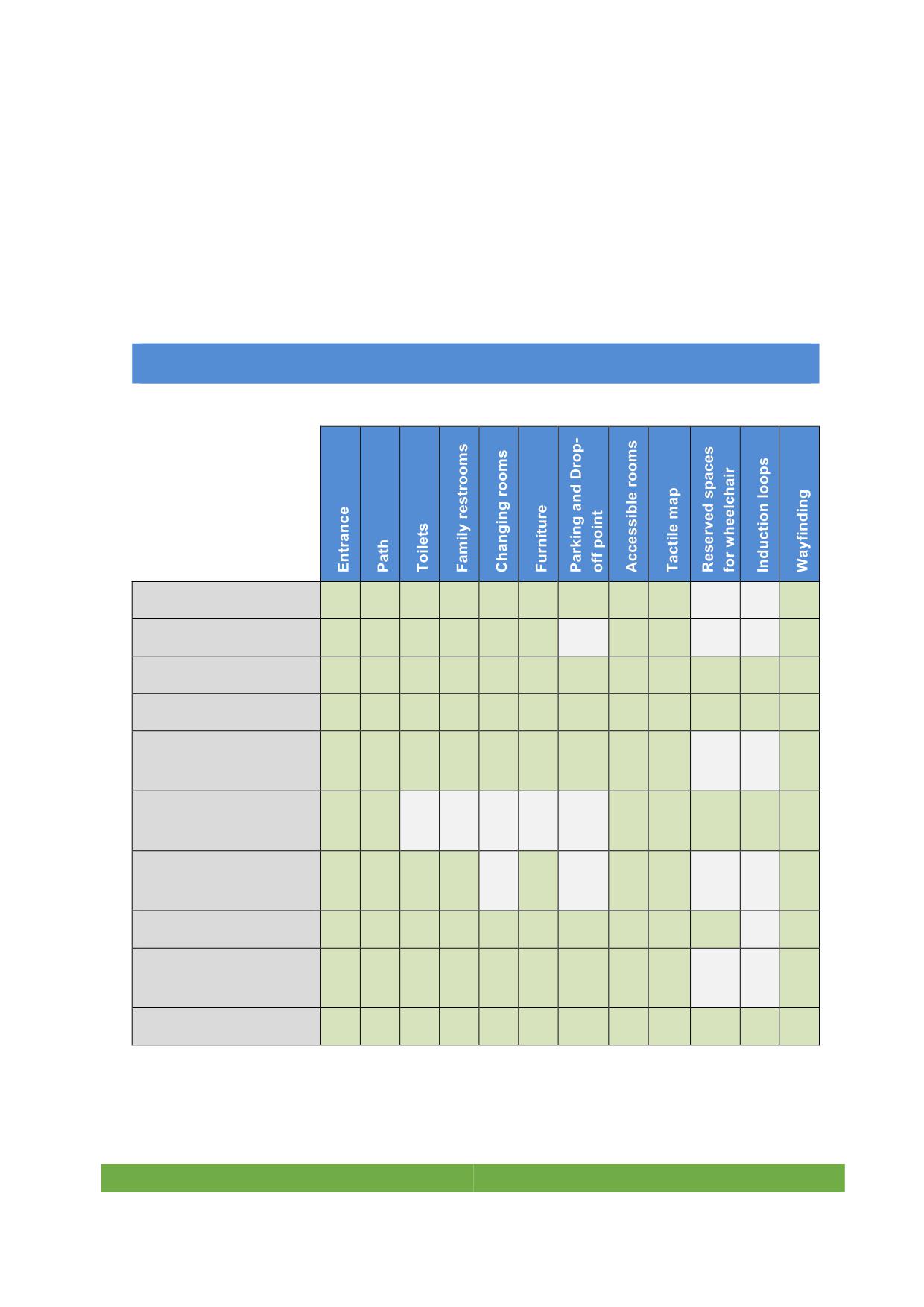
The following table displays the population groups benefiting from accessible provisions
when the requirements of this Code are followed. The green colour indicates
population groups that will enjoy more comfort while “X” indicates those to whom the
improvement is directly addressed.
LEVEL OF PERFORMANCE ACCORDING TO USERS
Universal Accessible Solutions
Children
X
X
X
Pregnant woman
X
Elderly people
X
X
Families
X
X
X
X
X
X
People with visual
X
X
X
X
X
impairment
People with hearing
X
X
X
impairment
People with
X
X
intellectual impairment
Mobility device users
X
X
X
X
X
X
X
X
X
X
Ambulant disabled
X
X
X
X
people
Tourist
X
X
Table 1. Level of performance according to users
16
3. Scope
This Code specifies a range of requirements for many of the elements of construction,
assemblies, components, vehicles and fittings that comprise the built environment and
transport services.
These requirements relate to the external environment, such as public open spaces, as
well as access to buildings, to circulation within buildings, to egress from buildings, as
well as public transport system’s vehicles, elements, stations and equipment.
The requirements are to be applied during the design, construction, renovations, and
alteration of sites, facilities, buildings, and elements of the built environment and
transportation systems, to the extent required by regulations issued by the Emirate of
Dubai under Law No. 2.
This Code does not apply to individual dwellings, only to common parts of multi-
occupancy residential buildings. However, it includes a section addressing requirements
for new convertible housing.
Nothing in these requirements prevents the use of designs, products, or technologies as
alternatives to those prescribed, provided they result in substantially equivalent or
greater accessibility and usability.
The dimensions stated in this Code are primarily based on adults, but it includes
specifications that address the requirements that should suit children and people with
different heights. If a facility is primarily to serve children, dimensions and other
provisions should be adjusted to make them suitable for children.
Dimensions are given in metric units. All dimensions in figures are given in meters or
millimetres and are measured to the centreline, unless otherwise specified.
The purpose of Section C, Accessible Transport, is to give guidance when creating
transportation systems that support equitable access and ease of travelling for all
persons regardless of their social, economic, physical, sensory or cognitive capacity.
Section C focuses on issues of Universal Accessibility and usability for persons with
functional limitations and should be used together with the other sections of this Code.
Section D, Wayfinding, establishes the minimum requirements for providing information
for orientation and navigating the public realm and buildings.
17
3.1. Scoping requirements
All areas of newly designed and newly constructed buildings and facilities and altered
portions of existing buildings and facilities shall comply with these requirements.
Where a site, building, facility, room, or space contains more than one use, each portion
shall comply with the applicable requirements for that use.
Temporary buildings and facilities provided for public use should also comply with this
Code.
Where public access is permitted during construction or maintenance of a facility, the
requirements of this Code shall be respected to provide safe and equitable use for
everyone.
3.2. Existing buildings and facilities
The accessibility conditions of the buildings shall be assessed and the owner shall
present to the authorities a proposal for adapting the building to the requirements for
existing buildings contained in the Dubai Universal Design Code within three years after
its publication.
Additions and alterations to existing buildings or facilities shall comply with this Code.
Each addition to an existing building or facility shall comply with the requirements for
new construction. Where existing elements or spaces are altered, each altered element
or space shall comply with the applicable requirements of this Code.
An alteration that decreases or has the effect of decreasing the accessibility of a
building or facility below the requirements for new construction at the time of the
alteration is prohibited.
Maintenance of all facilities, including public and private buildings, as well as
transportation facilities, shall guarantee accessibility continuity.
Buildings listed for their cultural interest or catalogued for their particular historical and
artistic value remain exempt from applying the accessibility requirements when they
contradict the preservation regulations of Dubai. However, they still need to incorporate
as many elements as possible to maximize accessibility conditions.
When a building is built in a flood zone the entrances of the building can have a change
in level from the exterior ground level.
18
Sports facilities shall follow the Paralympics Committee’s requirements, as long as
these requirements are greater than the Dubai Universal Design Code requirements.
Urban general planning and urban project developments shall ensure the accessibility
continuum with surrounding elements and areas, according to the criteria set in this
Code.
3.3. Transport
New vehicle procurement, retrofitting of existing vehicles, stations and stops including
rail, bus, marine vessel, school bus and accessible taxis shall have accessible features
meeting the technical and design requirements in the Code. The scope of this Code
does not cover air, intercity bus or intercity rail travel.
19
4. Definitions
1. Accessible path of travel
Allows a continuous and barrier free movement, with the combination of built elements
that guarantee anyone can enter, move, use, exit, orient themselves and communicate
autonomously and comfortably both in the public space, and around and inside the
buildings.
2. Accessibility
Accessibility include eases of independent approach, entry, evacuation, and/or use of a
building and its services and facilities, by all of the building’s potential users, regardless
of disability, age or gender with an assurance of individual health, safety and welfare
during the course of those activities.
3. Built Environment
External and internal environments and any element, component or fitting that is
commissioned, designed, constructed and managed for use by people.
4. Clear headroom
Free unobstructed vertical space to allow proper and safe passage.
5. Clear width
Free unobstructed space for access through a doorway, passage, stair, ramp, walkway,
etc.
6. Colour Blindness
The most common form of colour blindness is red/green deficiencies in which shades of
grey are generally detected in place of red and green. This should be considered when
using colour coding or coloured text.
7. Curb Ramp
Construction in the form of an inclined plane that makes it possible to pass from street
level to a higher accessible pedestrian path.
20
8. Functional limitations
Functional limitations are restrictions in performing fundamental physical and mental
actions used in daily life such as mobility (physical) or memory (mental).
9. Gangway
An inclined solid structure to connect a building or a vessel with a berth, with handrails
at each side.
10. Handrail
Component of a stair or of a ramp or other building component that provides guidance,
balance and support.
11. Headroom
Clear vertical space above one’s head, as in a vehicle or room.
12. Interaction space
The interaction space is the space required by a person to interact with another person,
furniture, appliance, machine or another item.
13. Kneeling
When a vehicle is lowered at a boarding/disembarking location to reduce the vertical
gap between the entry/exit point to the vehicle and the boarding platform or ground
level.
14. Landing
Platform or part of a floor structure at the end of a flight of stairs or a ramp or at the
entrance to a car lift.
15. Light Reflectance Value (LRV)
The proportion of visible light reflected by a surface at all wavelengths and directions
when illuminated by a light source. LRV is also known as the luminance reflectance
factor. The LRV is expressed on a scale of 0 to 100, with a value of 0 for pure black and
a value of 100 for pure white.
16. Luminance
The amount of light emitted from a surface or source in any given direction.
21
17. Maneuvering area
Minimum three-dimensional spaces within which it is feasible to complete a maneuver
to gain access to a specific facility, component or fitting, in particular while using a
wheelchair or a walking aid.
18. Mobility aid
A device that is used by persons with functional limitations to assist walking. Examples
include canes, arm crutches, and walkers. Within this Code the term “wheelchair” is
used to include manual wheelchairs, sports chairs, electric powered wheelchairs and
mobility scooters, unless otherwise stated.
19. Mobility device
A manual or motorized device to be used by persons with functional limitations in their
mobility. Examples include manual and sports wheelchairs, electric powered
wheelchairs, and three and four-wheeled mobility scooters.
20. Nosing
Projecting front edge of a tread or landing that can be rounded, chamfered or otherwise
shaped.
21. Operable with the elbow
This expression is frequently used in this Code. It is used as an abbreviated explanation
of the manual operations that can be executed:
• With one hand only
• Without wrist turning
• Without finger grip
• Not requiring very precise psychomotor skills
• With low strength requirements
22. PTV
Pendulum Test Value. This parameter provides information about the slipperiness of a
floor surface. Many floor manufacturers provide this value in the technical specifications
of their products. Pendulum Test Value (or sometimes BPN, British Pendulum Number,
or even SRV, Slip Resistance Value). The standard EN 13036-4 determines the test
methods.
22
23. Ramp
An inclined solid flat plane structure that is steeper than 5 % from the horizontal.
Depending on the length it shall include an intermediate landing, which makes it
possible to pass from one level to another.
24. Rise
Vertical distance between the upper horizontal surfaces of two consecutive treads, or of
a landing and the next treads above or below it, or of a flight between consecutive
landings.
25. Riser
Vertical component of a step between a tread or a landing and the tread or a landing
above or below it.
26. Reflectance
Measure of light reflected in a given direction by a surface and which is expressed in a
unit term from 0 to 100 scale, respectively, that represents a grey scale progression
from the notional extremes of total light absorption (black) to total light reflection (white).
27. Service animal
Any guide dog, signal dog, or other animal individually trained to work or perform tasks
for an individual with a disability, including, but not limited to, guiding individuals with
impaired vision, alerting individuals with impaired hearing to intruders or sounds,
providing minimal protection or rescue work, pulling a wheelchair, or fetching dropped
items. Service animals shall be identified with a certification.
28. Shall
It is mandatory to do it.
29. Should
It is recommended to do it.
30. Visual contrast
Visual perception between one element of a building and another
23
31. Wayfinding
Descriptive of a system whereby appropriate information is provided to assist a person
to pass through the built environment towards a specific destination. Wayfinding
includes orienting oneself, knowing one’s destination, following the best route,
recognizing one’s destination and finding one’s way back out. People who are blind or
who have a vision impairment benefit from tactile information to facilitate wayfinding.
24
Section B
Accessible Built Environment
25
Section B - Accessible Built Environment
5. Common accessible elements for outdoor and
indoor areas
5.1. Accessible path of travel
Accessible paths of travel shall present the following characteristics:
1.
The width of the path free of obstacles should be enough to allow all pedestrians
foreseen in all directions; considering 1000 mm per each simultaneous pedestrian. It
shall be always more than 2000 mm and no one obstacle can reduce it to less than
1200 mm.
2.
The accessible path shall be linear and continued, while avoiding direction changes
between pedestrian crossings.
3.
All intersections shall be clearly visible and defined with safety and traffic control
elements such as signs or lights. Pedestrian crossings shall be clearly distinguished
from the road with contrasted colour marks.
4.
In pedestrian crossings, when there is a height change, curb cuts shall be provided
following the requirements of section 6.3.
5.
The maximum permitted gradient for a running slope in accessible paths is 5%.
6.
The clear headroom along the entire path shall be at least 2200 mm.
7.
Uneven surfaces in accessible paths should be avoided and the maximum height of
any irregularity shall be 5 mm.
8.
The accessible path shall not have dangerous unprotected level changes.
Unevenness, gaps and openings with a height difference greater than 500 mm
should have guardrails.
9.
Accessible paths shall be free of protruding objects like vegetation, furniture and
signs.
26
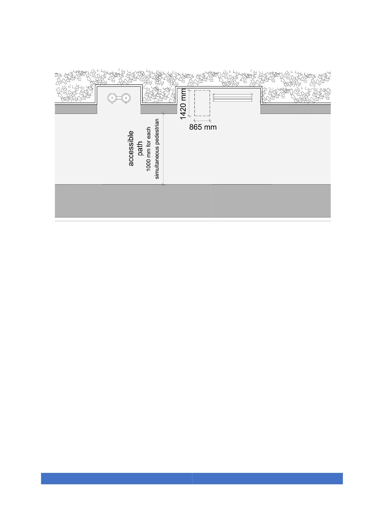
Figure 1. Accessible path of travel free of obstacles
10. Accessible elements such as paths, crossing, stairs, etc., shall have a luminance of
at least 100 lux. All lighting changes along an accessible path shall be gradual to
prevent glare.
11. Drain grids shall never be within the accessible path or the accessible pedestrian
crossing.
12. In outdoor areas, accessible paths shall be free of obstacles and located between
the buildings facade and the furniture zone adjacent to the curb.
13. Parking entrances shall not modify the slope or the width of the accessible path.
14. The curb height shall be between 100 mm and 150 mm.
15. Utility covers should be avoided in accessible walking paths. When placing utility
covers out of the accessible path is impossible, the maximum height difference shall
be 5 mm. When placing drain grids out of the accessible path is impossible, the
maximum dimensions of the holes shall be 15 mm.
16. Standing water should be avoided with a cross slope up to 2%.
17. If there is a pedestrian bridge along an accessible path of travel it shall provide a
ramp or an elevator and shall be shaded.
27
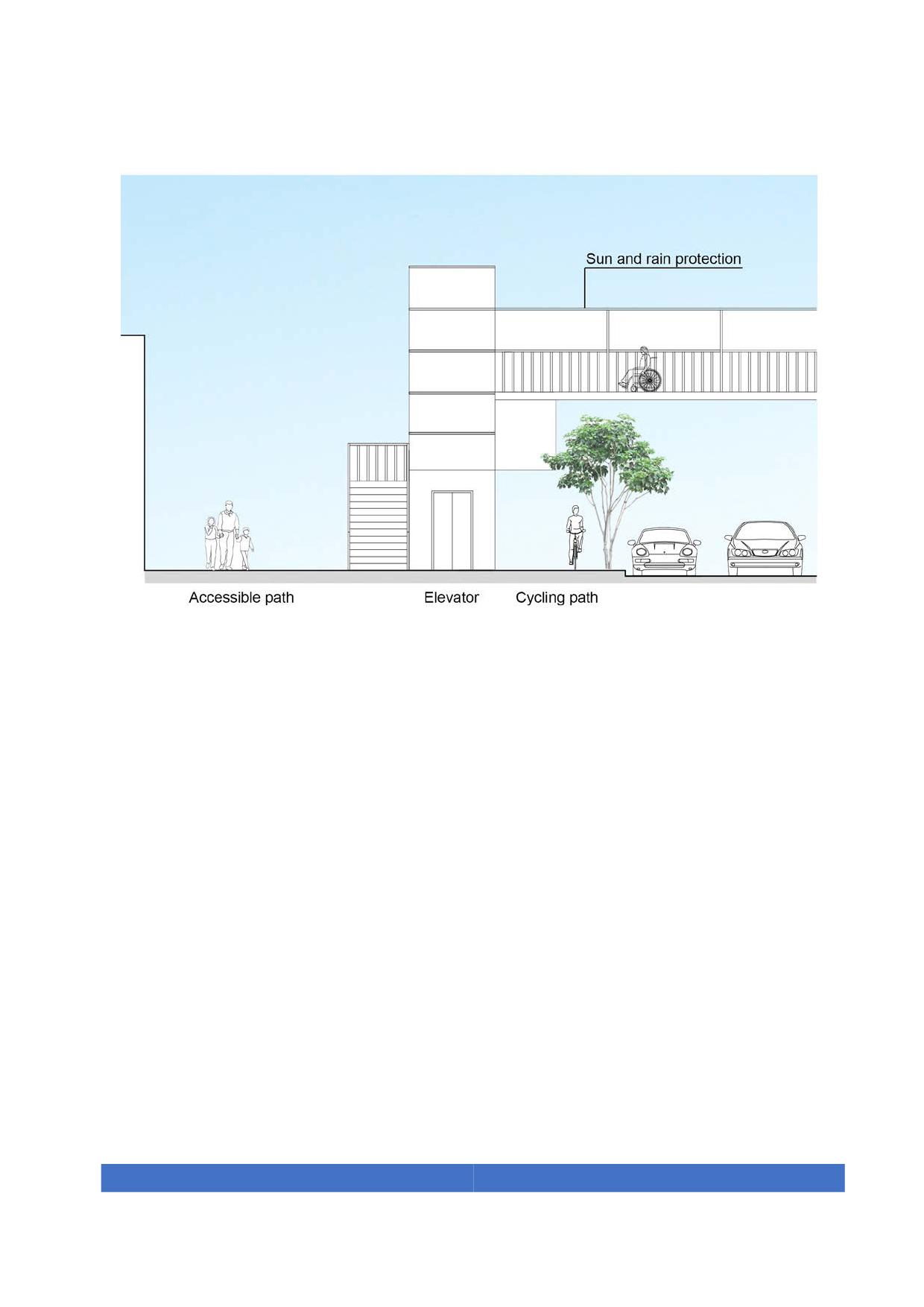
Figure 2. Example of a bridge with elevator
28
5.2. Floor surfaces
Slip resistance is a requirement in making pavements and surfaces accessible.
Paving in accessible paths shall meet the following conditions:
1. Slip resistance
Levels of slip resistance have to fulfil the requirements outlined in table 2.
Pavement Slip resistance
Floor pavement slopes
Pendulum Test Value (PTV)
Dry areas indoor
Level surface
Between 15 and 35
Inclined surfaces with slopes less than 5%
Inclined surfaces with 5% slopes or greater
35 or more
Wet areas and outdoor
Level surface
Between 35 and 45
Inclined surfaces with slopes less than 5%
Inclined surfaces with 5% slopes or greater
45 or more
Streets pavement, swimming pools and
45 or more
showers
Table 2. Pavement slip resistance
2. Pendulum Test Value (PTV) should to be calculated using the pendulum technique.
The above table shows slip resistance values for accessible pedestrian walking.
3. Pavement surfaces shall be firm, smooth, stable, and slip resistant.
4. Tiles presenting rounded edges and excessive joints shall be avoided in accessible
paths to prevent wheel vibration, tripping and noise.
29
5. The ground pavement cannot have loose elements and must allow for movement or
dragging.
6. Rugs and carpets shall be firmly fixed to the floor and shall allow easy movement for
wheelchair users.
7. Floor pavement shall not produce glare.
8. The pavement shall present reflectance contrast with the surrounding pavement of
at least 30 points LRV (Light Reflectance Value), or by an easily perceptible (by the
foot or the cane) texture difference. These pavements can present less contrast if
they are separated by a pavement strip of at least 300 mm presenting the required
contrast or by an easily perceptible texture difference.
9. Lighting installed in floors is not permitted if it produces glare in the area of
accessible paths.
10. Lighting installed in floors shall not produce heat.
11. Imperfections or irregularities in the floor surface that imply a level difference of more
than 5 mm or holes of more than 15 mm diameter are not allowed. These level
differences can be generated due to the material selection or because of a lack of
maintenance. This especially includes manhole covers grids and grills installed in
public spaces.
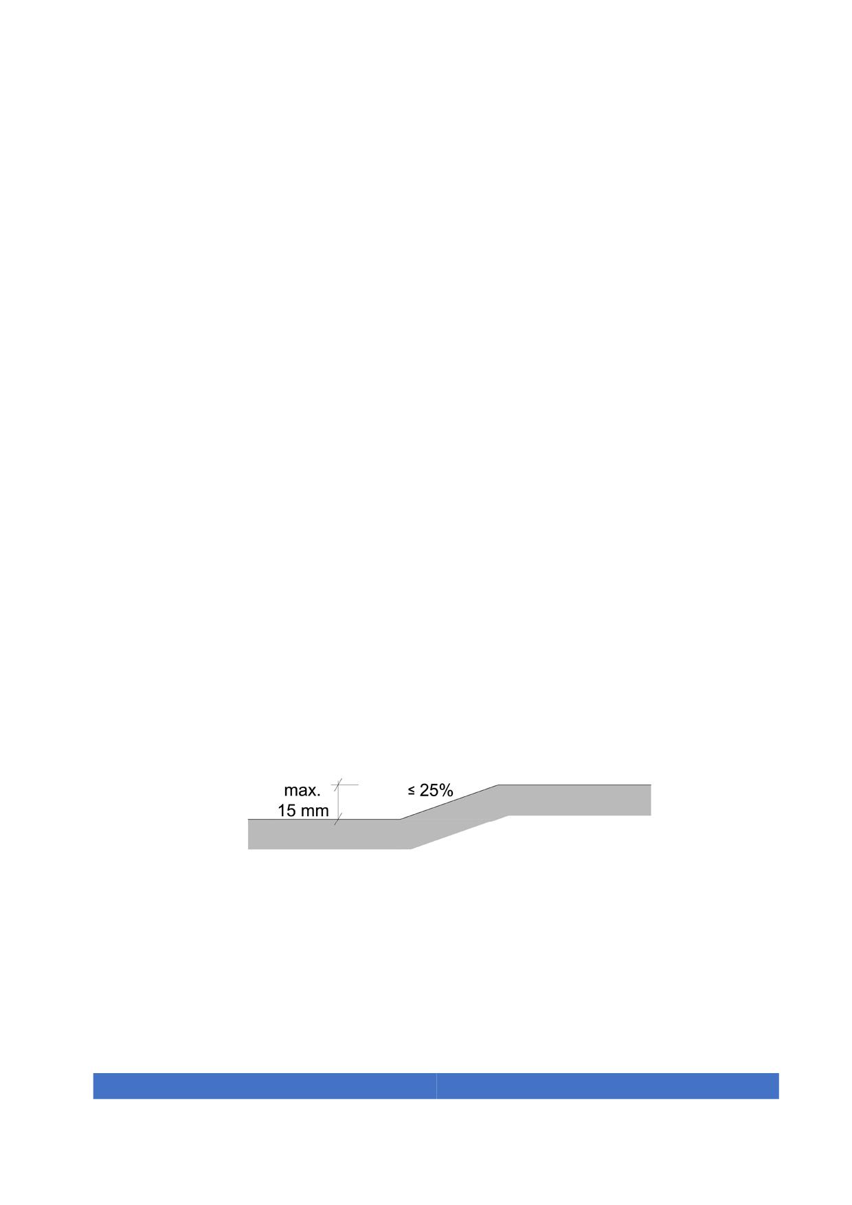
12. Changes in level of maximum 15 mm should be designed with a 25% maximum
gradient slope.
Figure 3. Maximum gradient slope for changes in level of at most 15 mm
13. When grate openings are longitudinal, they should have a perpendicular orientation
to the pedestrians’ direction of travel.
30
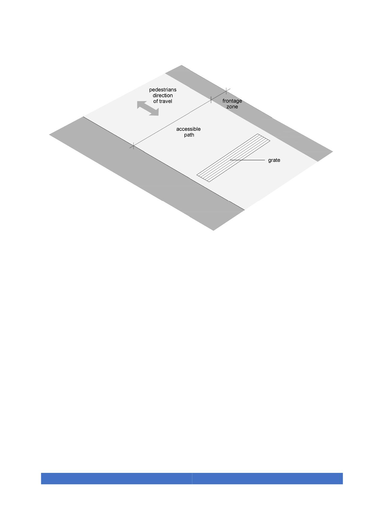
Figure 4. Grate with perpendicular orientation
14. It is not permissible to install grates on the lower level of the pedestrian crossing
curb cuts.
15. Trees adjacent to an accessible path shall be protected with walkable grates,
especially when its location is less than 2000 mm to a building façade.
31
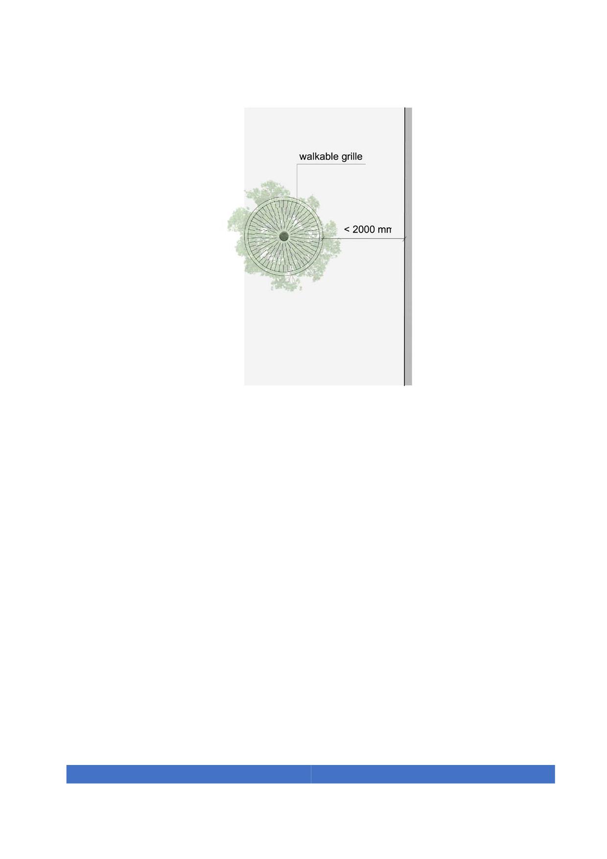
Figure 5. Walkable grille in tree grate
5.3. Tactile Surfaces
Tactile pavements are textured surfaces with contrasted colour that are perceptible and
identifiable by feel or cane or residual functional vision that warns or informs people with
visual disabilities.
Tactile pavements shall have a reflectance contrast with the surrounding pavement of at
least 50 points LRV and the height or depth of this pavement cannot be greater than 4
mm.
Tactile pavements must be installed according to the following criteria:
1. Detectable warning surface: used as a warning of upcoming level changes or
obstacles on the course of travel. Warning pavement shall be constructed of
truncated cones arranged in a square grid or diagonal rows and installed with bands
oriented in the crosswise direction of the course of travel. It must be installed along
the entire width of the element and not less than 300 mm from the beginning of the
dangerous element. The warning surface shall have a width between 300 mm and
400m.
32
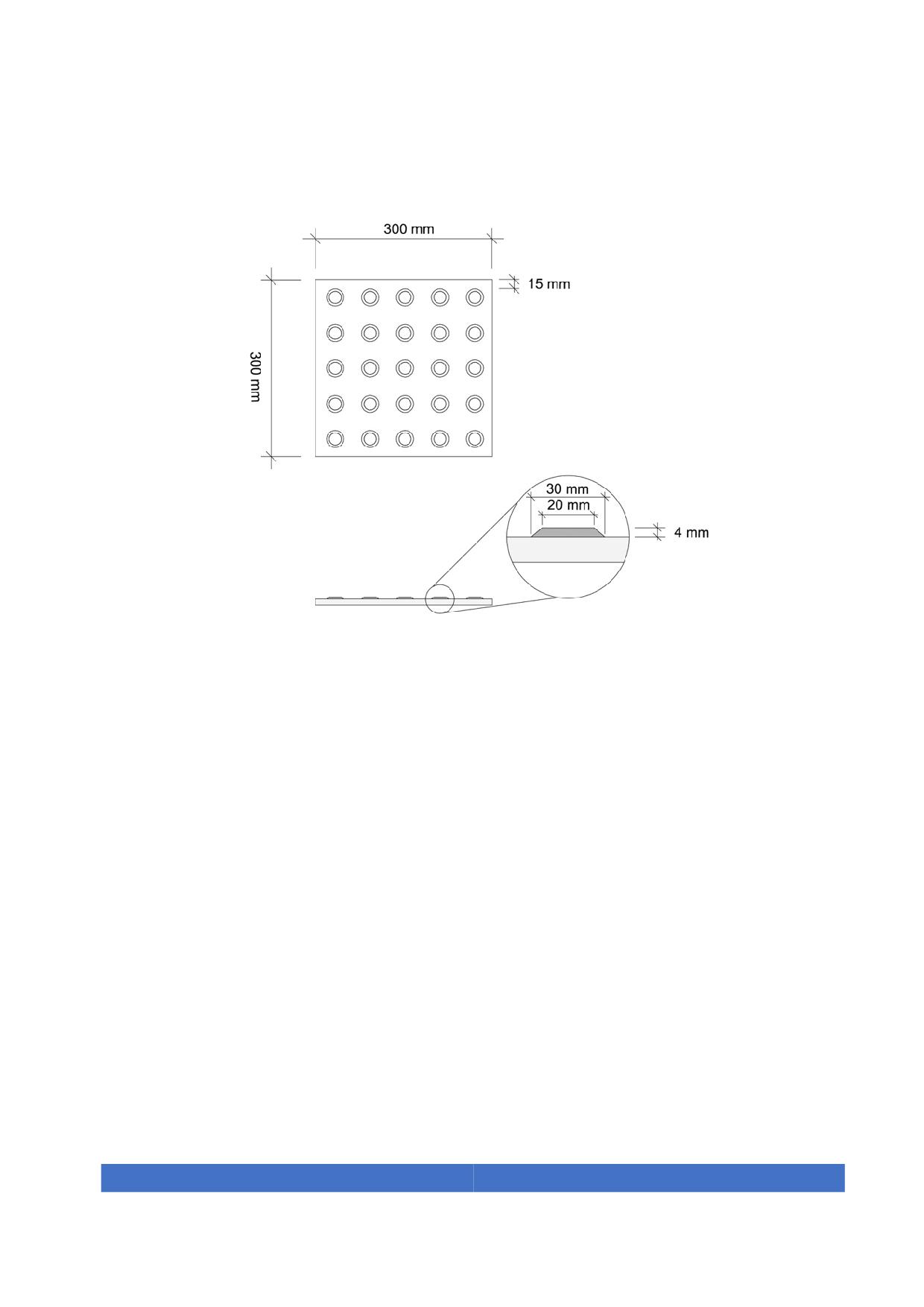
Figure 6. Warning pavement dimensions
The most common elements where warnings are required include stairs, ramps, rail and
port platform borders, and unprotected changes in level among others.
2. Tactile guiding surfaces: this element is used as a directional sign to assist the
independent mobility of people with visual disabilities. Guiding patterns should be
constructed of flat-topped elongated bars. Bars must be oriented in the direction of
the course of travel.
The tactile guiding surface shall have a minimum width of 400 mm. The distance among
longitudinal stripes can’t exceed 32 mm.
33
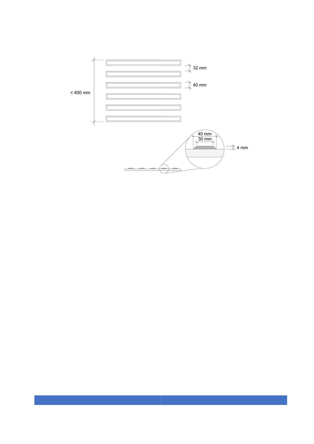
Figure 7. Guiding pavement dimensions
34
5.4. Protruding objects
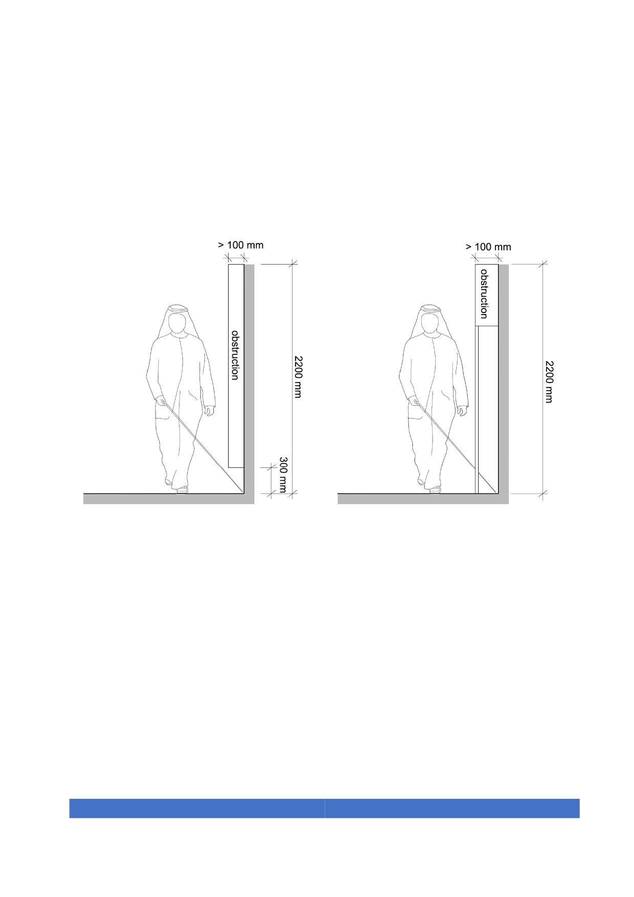
Objects shall not protrude into the pedestrian path more than 100 mm.
In case of elements protruding more than 100 mm from façades, posts or other
elements, the protruding edge shall extend to the floor or be at least 300 mm above the
floor, according to the illustration below.
Figure 8. Lateral protruding object limits
For all furniture the detection cone rule shall be followed. The detection cone is an
imaginary shape that describes the obstacles to be detected by blind persons with a
white cane.
The cone has a base of 500 mm diameter located 300 mm above the ground level. The
apex of this cone is located at a height of 900 mm height above the ground. The values
of the cone are shown in table 3.
Detection cone diameters depend on the height (above floor level) of the object.
35

Detection cone diameter depending on the height (from the floor level)
Height
Diameter Ø
900 mm
50 mm
800 mm
80 mm
700 mm
160 mm
600 mm
250 mm
500 mm
340 mm
400 mm
420 mm
300 mm
500 mm
Table 3. Parametric values of the detection cone
Depending on their height, bollards or similar elements that are located near an
accessible path shall have a diameter equal to or greater than the values specified in
the table above.
36
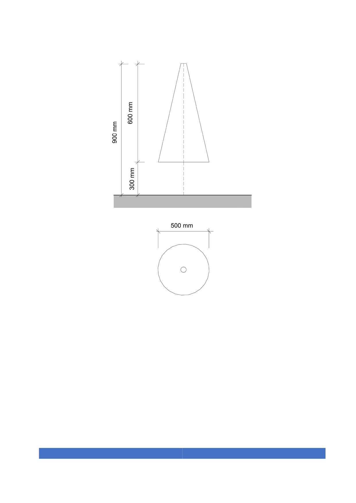
Figure 9. Dimensions of the imaginary detection cone
37
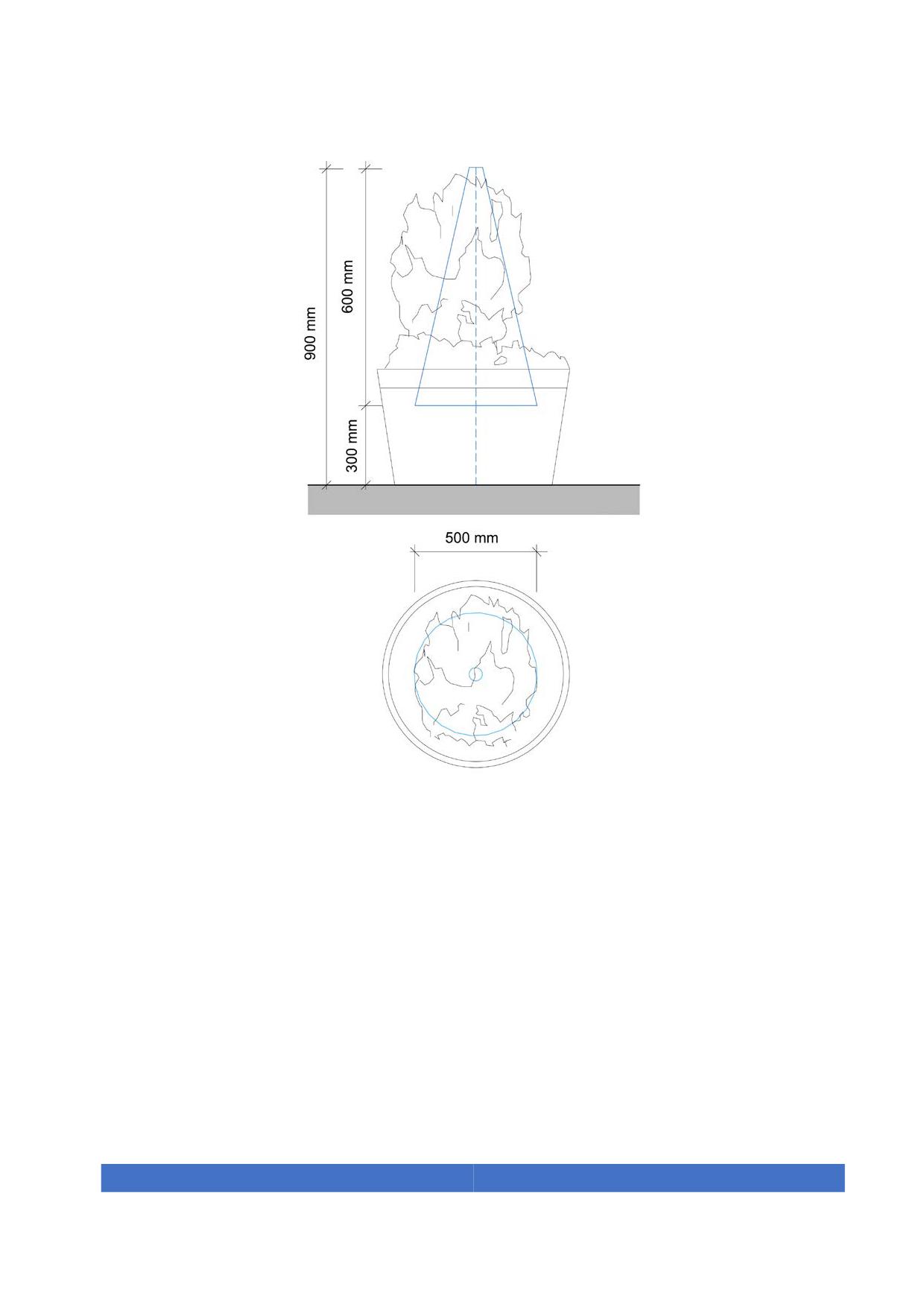
Figure 10. Example of a planter that correctly exceeds the imaginary detection cone.
5.5. Interaction space
The interaction space is the space required by a person to interact with another person,
furniture, appliance, machine or another element.
This space is also used by a person to transfer from a wheelchair to a seat or a toilet or
to park a pram.
The interaction space shall not invade the accessible path. The interaction space can
be frontal or lateral.
38
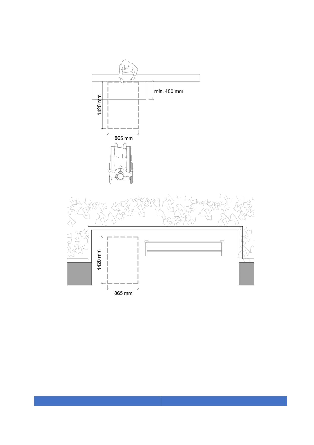
Figure 11. Interaction spaces in front of a desk and beside a bench
The interaction space dimensions are 865 mm x 1420 mm.
39

When objects protrude into the interaction space, like shoes in a praying room entrance,
paper bin in the toilet’s lateral approach space, or other similar cases, the interaction
space can be marked with a carpet or painting as shown in the following illustration:
Figure 12. KEEP CLEAR area
5.6. Changes in level and guardrails
Guardrails must be at least 1100 mm height. This parameter is measured vertically from
the ground level, to the highest point of the guardrail.
The guardrails must have sufficient strength and stiffness to withstand a horizontal
uniformly distributed force of 3.0 kN/m.
The guardrails cannot be easily climbable.
Openings on guardrails shall not allow a 100 mm diameter sphere to pass through.
When guardrails are installed to protect slopes, they must have a continuous base in
their entire length from the floor surface to a minimum height of 100 mm.
40
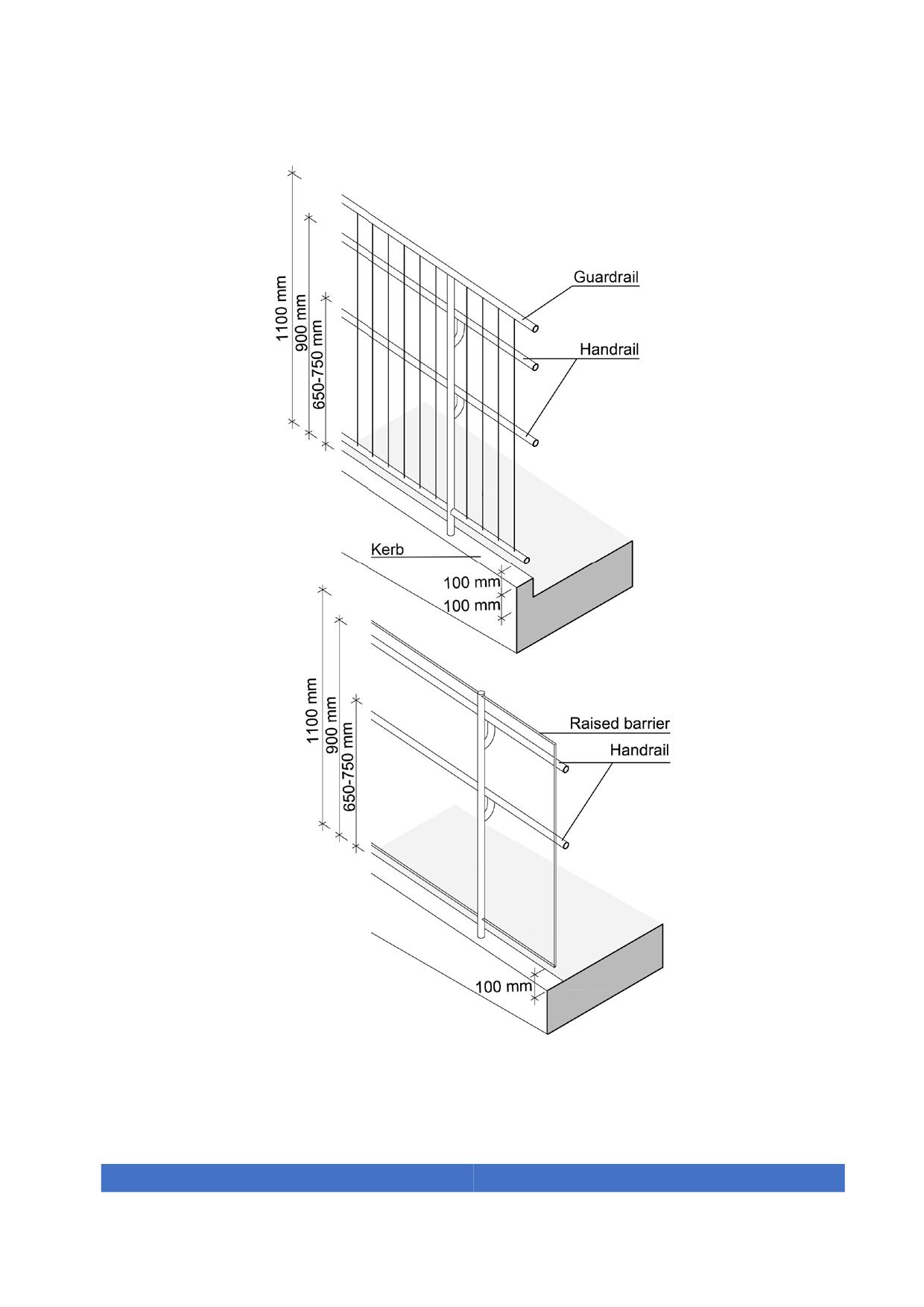
Figure 13. Section of guardrails with and without glass
41
5.7. Ramps
Ramps should be used when a change in level has a gradient greater than 5%.
The maximum slope is 8% or 1:12.
The maximum cross fall gradient is 2%.
The slope of a ramp must meet the following specifications:
Maximum Rise
Slope
Length between landings
Recommended
Maximum
Recommended
Maximum
1500 mm
5,1% - 6%
8%
7 meters
10 meters
1000 mm
≤ 7%
8%
5 meters
7 meters
500 mm
≤ 8%
8%
2 meters
5 meters
Table 4. Ramp rises
5.7.1.
Ramp runs
Ramp runs shall fulfil the following requirements:
1. The maximum length is 10 meters between landings.
2. The beginning and the end of each ramp run shall have a warning surface following
the requirements of section 5.3.
3. The run usable width shall be 1000 mm.
4. Ramp widths shall be free of obstacles. The usable width of 1000 mm is measured
between the handrails. If the ramp is open, it shall have an outside edge protection
or a lateral protection element of at least 100 mm in height.
5. Curved ramps are not permitted.
42
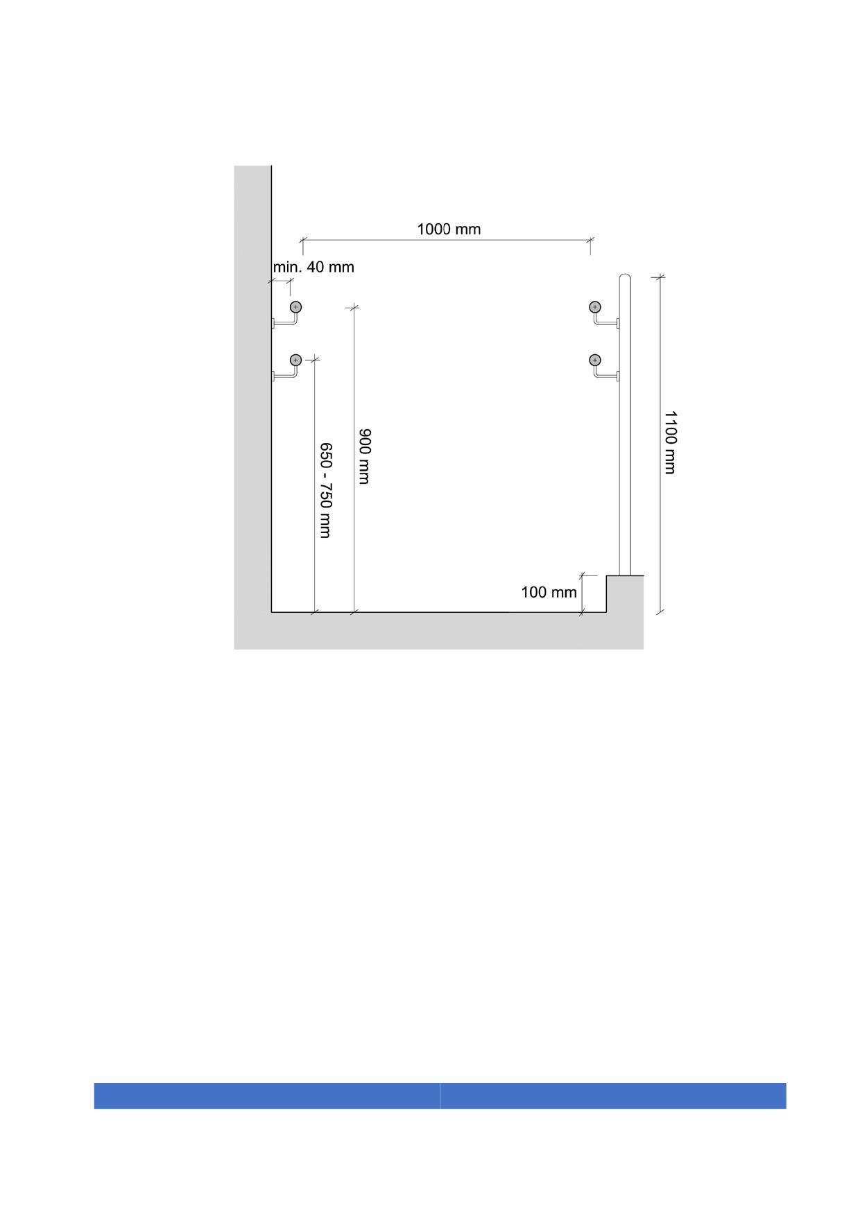
Figure 14. Transversal section of a ramp
5.7.2.
Landings
Landings shall fulfil the following requirements:
1. There are level landings required at the beginning and at the end of every ramp run.
These landings shall have a minimum surface of 1500 mm x 1500 mm.
2. Landings should be level with less than 2% slope in the course of travel and
crosswise directions.
3. Corridors located in landings shall have no less than 1200 mm width.
4. Doors shall be located at least 1500 mm away from the start or end of each ramp
run.
43
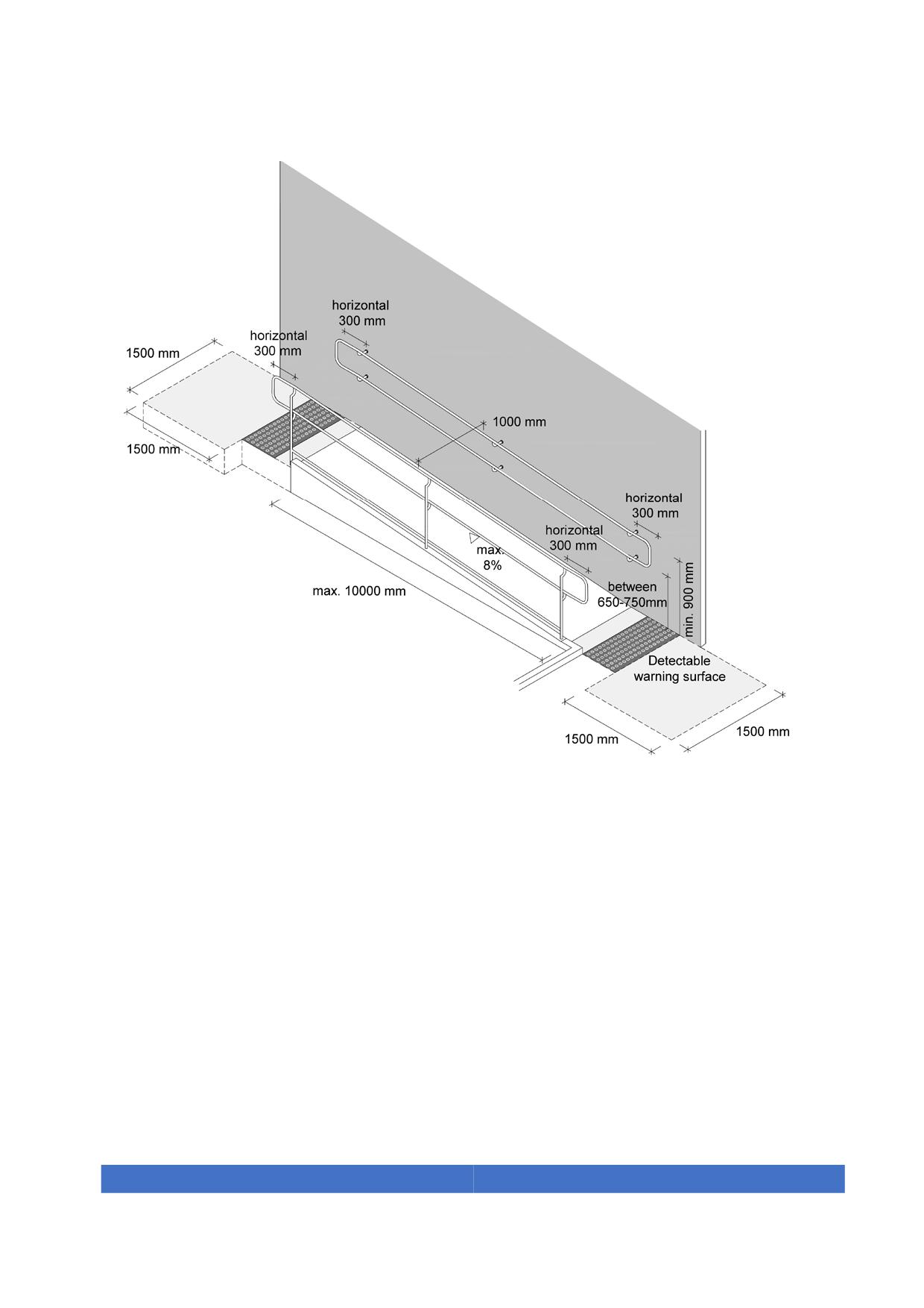
Figure 15. Maximum rise and length for ramps with details of handrails required and
different alternatives for handrail ends
44
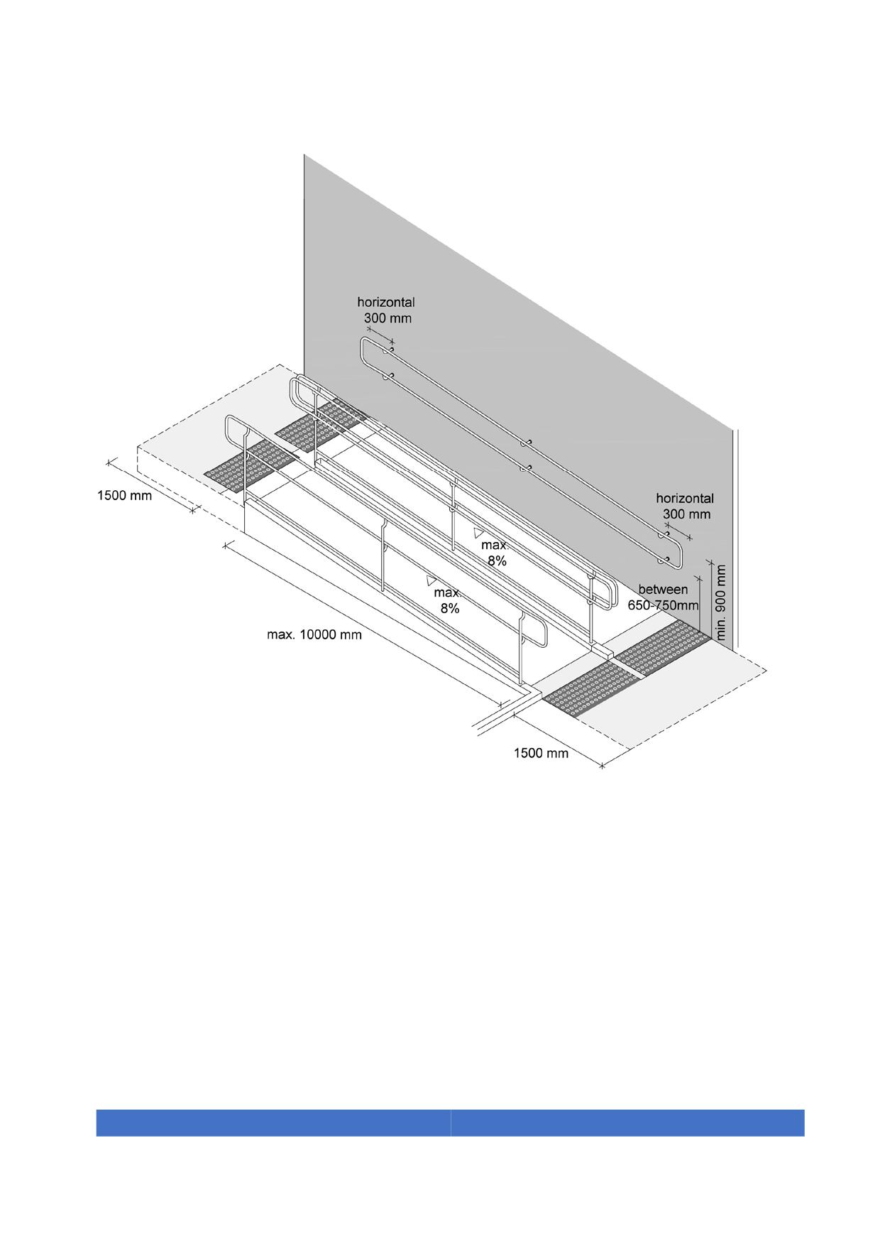
Figure 16. Example of a ramp with an intermediate handrail
45
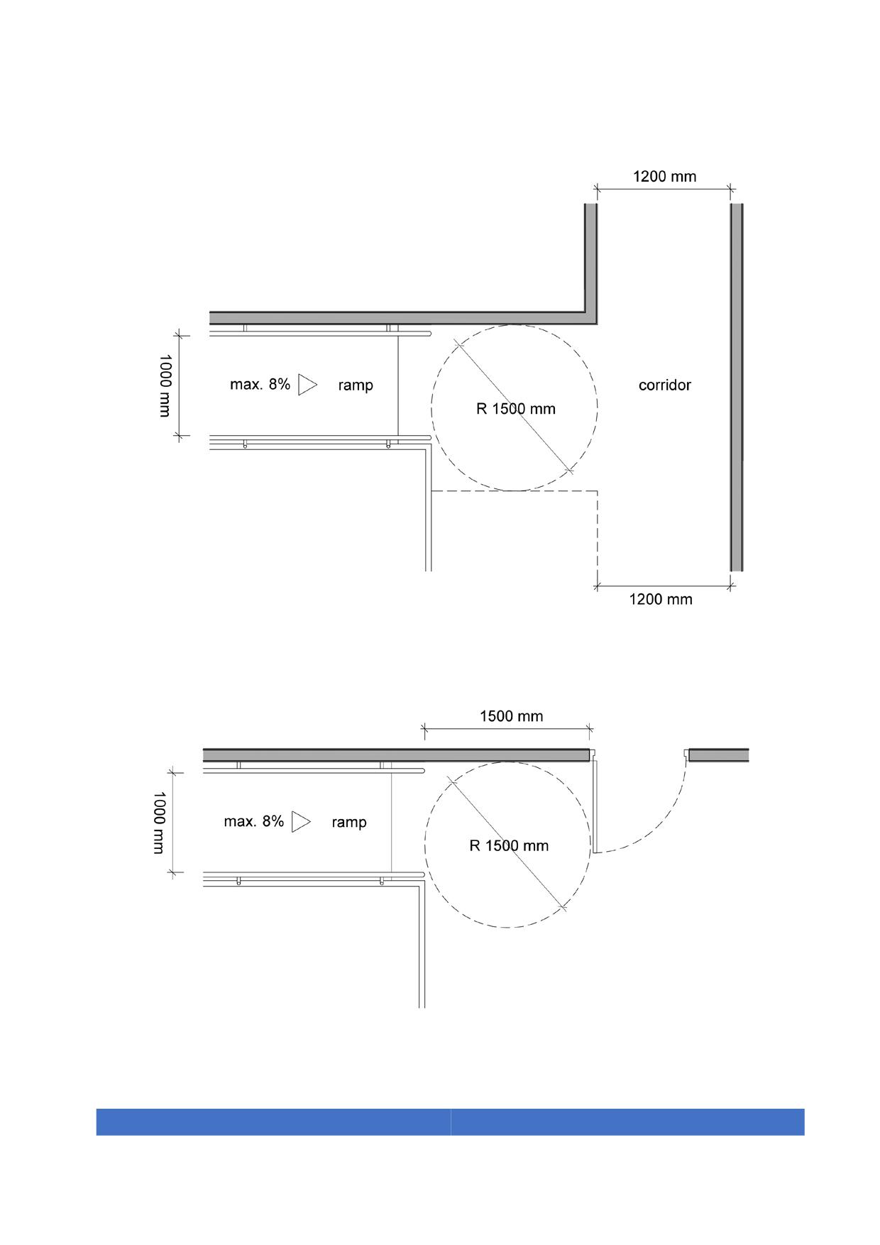
Figure 17. Dimension of corridors in landings
Figure 18. Door location near ramps
46
5.8. Stairs
Stairs should include as many accessible elements as possible.
5.8.1.
Steps
Steps shall the following characteristics:
1. Rises shall have a maximum height between 150 mm and 176 mm.
2. In straight flights, the dimension of the stair tread must be between 300 mm and 340
mm.
3. The rise R and tread T must meet the following relation: 650 mm < 2R + T < 700
mm.
4. Curved stairs should be avoided.
5. No open risers or discontinued treads are allowed.
Figure 19. Open risers are not permitted
6. The run of a step is the dimension measured from the edge of the nosing of a tread
to the vertical projection of the nosing of the next step.
47
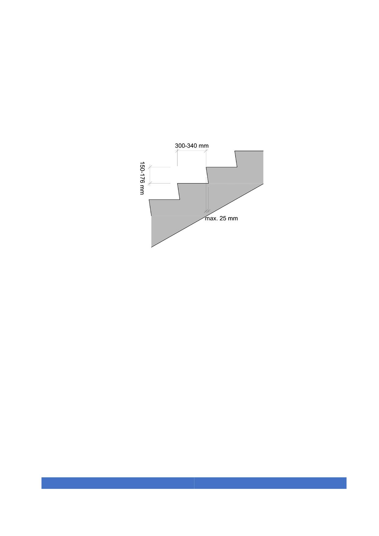
7. The projection of a step nosing over the tread below shall be avoided, and if present,
it shall be at a maximum of 25 mm.
8. At least 30 mm from the step edge shall present a reflectance contrast of at least 30
LRV points against the step surface.
9. In a staircase, all the steps shall have the same height with a tolerance of ± 4 mm.
Figure 20. Step nosing is not advisable and is limited up to 25 mm
5.8.2.
Stair flights
Each stair flight must meet the following characteristics:
1. A warning surface as per section 5.3 shall be provided at the beginning and the end
of each stair flight.
2. Each flight shall have between 3 steps and maximum of 12.
3. The usable width of the flight shall be at least 1200 mm.
4. The width of stairs should be free of obstacles overhead, particularly the underside
of the stairs themselves. The minimum usable width is measured between walls or
guardrails, without deducting the space occupied by the handrails as long as they do
not protrude from the walls or guardrails more than 120 mm.
5. Illumination at the top and bottom and along of the flight should be, at least 200 lux.
48
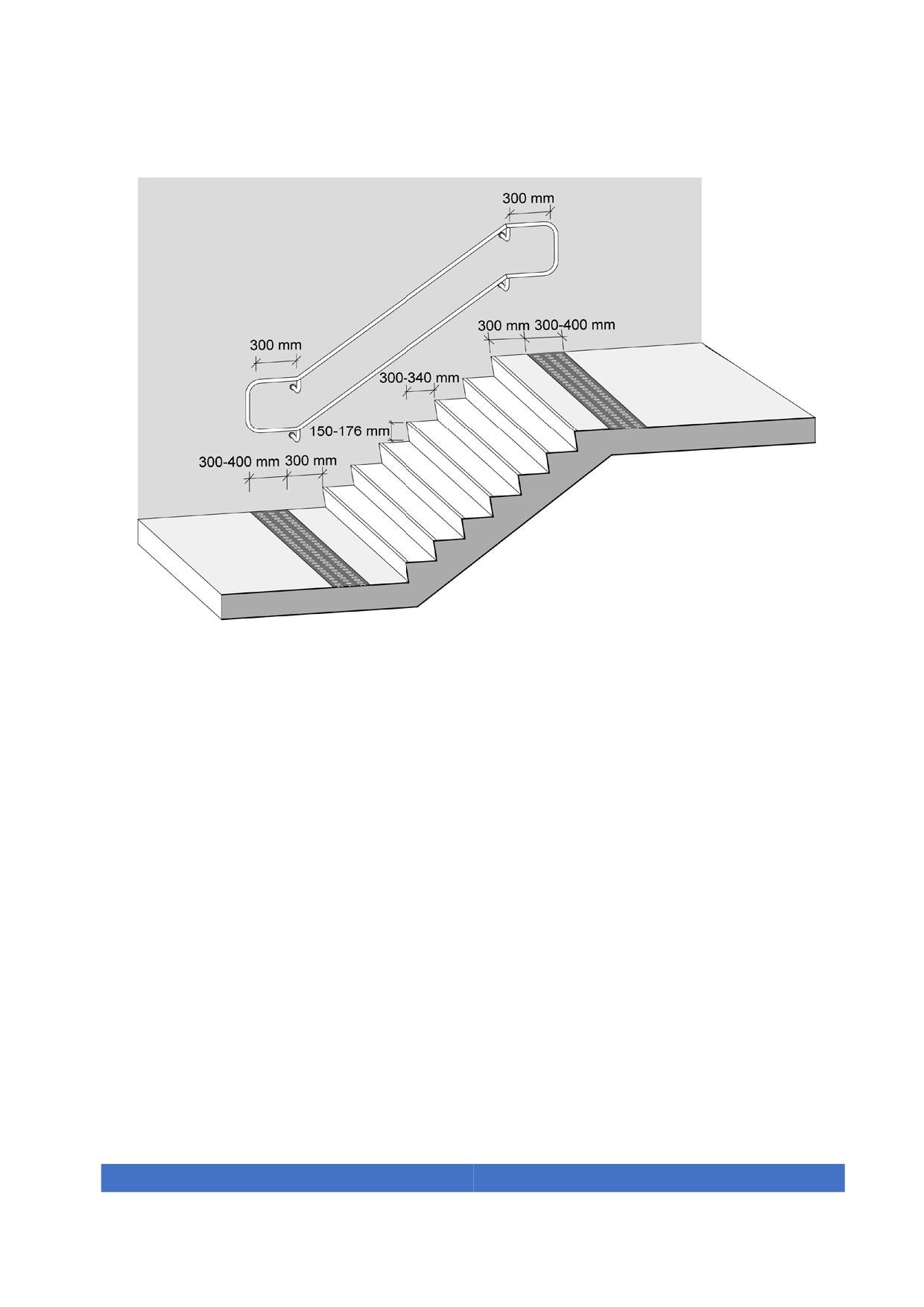
Figure 21. Section of a stair
5.8.3.
Landings
Each stair landing must meet the following characteristics:
1. Landings located between stairs flights in the same direction should maintain at least
the same stair width and have a minimum length of 1200 mm.
2. When there is a directional change between two flights, the width of the landing shall
not be reduced. This width must be free of obstacles and free from any door
opening.
49
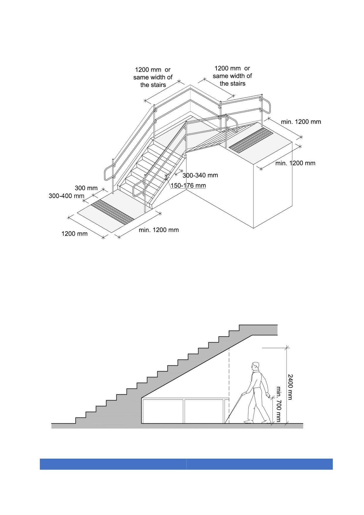
Figure 22. Stair with landings
All open spaces lower than 2400 mm under a stair shall be protected with a handrail or
fixed equivalent element to protect people from the overhead hazard, according to the
figure below.
Figure 23. Spaces under stairs shall be protected
50
5.9. Handrails
Stair and ramp handrails must meet the following characteristics:
1. Stairs and ramps with a change in level greater than 500 mm must have continuous
handrails on both sides with a 300 mm horizontal extension at its ends. Any of the
three solutions displayed in the figure 15 can be applied.
2. When the stair widths are greater than 2100 mm an additional intermediate handrail
should be installed. The width between intermediate handrails should be at most
2100 mm.
3. In ramps, the distance between the handrails shall be 1000 mm as displayed in
figure 14.
4. The handrail should be mounted at a height of 900 mm. An additional handrail shall
be provided at a height between 650 mm and 750 mm.
5. The handrails must be safely secured. Handrails must have an anatomical design
that allows adjustment to the hand with a circular section of 30 mm to 40 mm
diameter or an equivalent gripping surface. Handrails must be separated from the
wall surface at least 40 mm. The handrail section and its mounting system should
not interfere with the continuous gripping surface.
6. Handrails must have a contrasted reflectance of at least 30 points LRV against its
backg0round.
7. All handrail materials exposed to sun radiation shall not reach temperatures that
may damage the users.
51
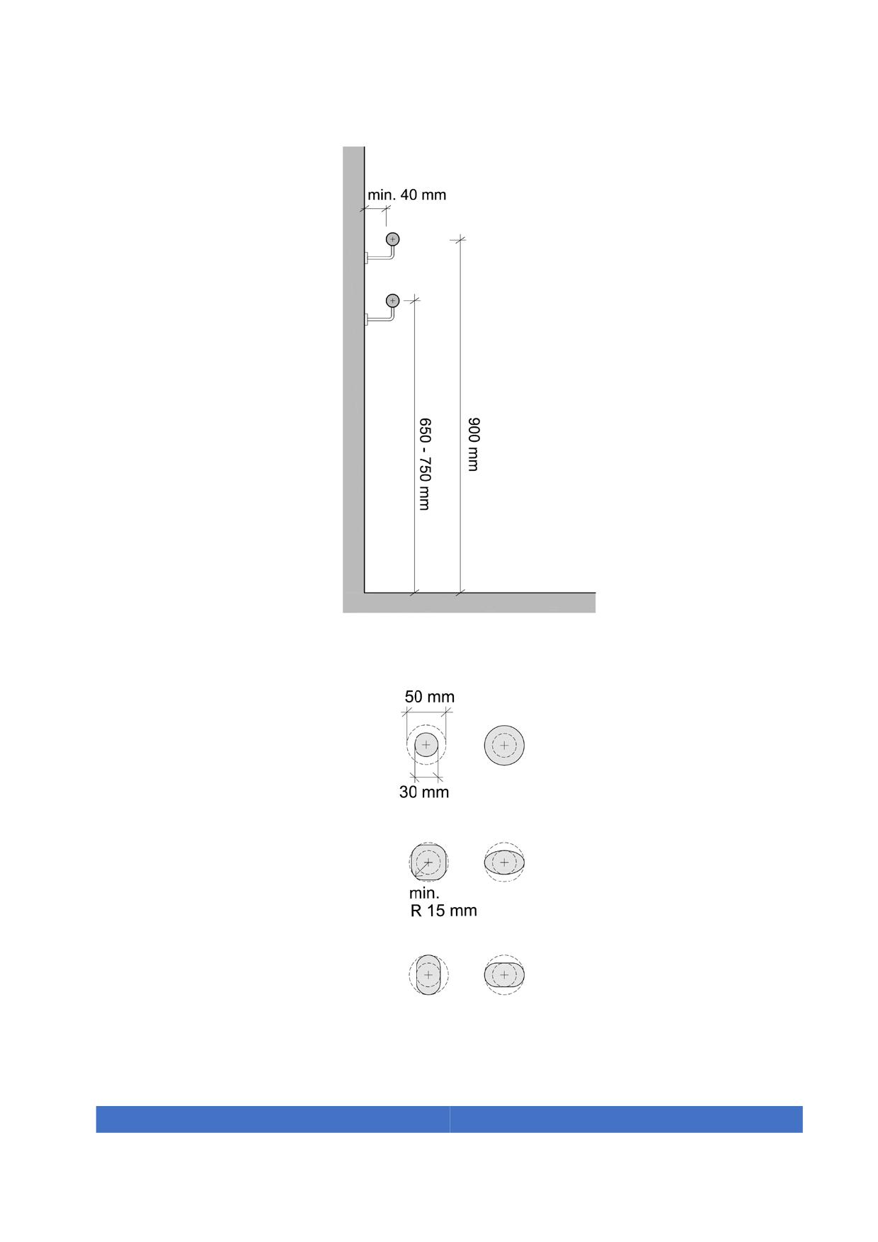
Figure 24. Dimensions of handrails
Figure 25. Examples of accessible handrail profile
52
5.10. Elevators
Elevators placed in public areas must be accessible from the ground floor.
An elevator, lift or platform should be provided in every building with more than one
floor.
The requirements to be fulfilled by an accessible elevator are:
1. The dimensions should be appropriate for the intended number of users and in all
instances equal to or bigger than the specified minimum dimensions of the cabin.
2. Depending on the number and position of the doors, dimensions are shown in the
following table:
Dimensions of the cabin (wide x deep)
Minimum
Recommended
One door cabin
1200 mm x 1500 mm
1500 mm x 1500 mm
Cabin with two opposing doors
1200 mm x 1500 mm
1500 mm x 1500 mm
Cabin with two doors in 90° angle
1500 mm x 1500 mm
2000 mm x 2000 mm
Table 5. Dimensions of elevator cabins in public areas
3. The elevator doors of the floor and the cabin must be automatic, have a minimum
width of 900 mm, minimum height of 2000 mm, and present colour contrast against
the walls.
4. In front of the elevator access door and in front of the hall call button there should be
a minimum clear manoeuvring space of 1500 mm x 1500 mm.
5. Elevator call buttons shall be located at a height between 900 mm and 1200 mm.
6. Floor indicators shall be located at a height of 1830 mm.
7. A mirror shall be placed inside the elevator on the wall opposite to the door, from the
handrail height upward, covering the full back panel.
8. At least two handrails shall be placed at a height of 900 mm ± 100 mm from the
floor.
53
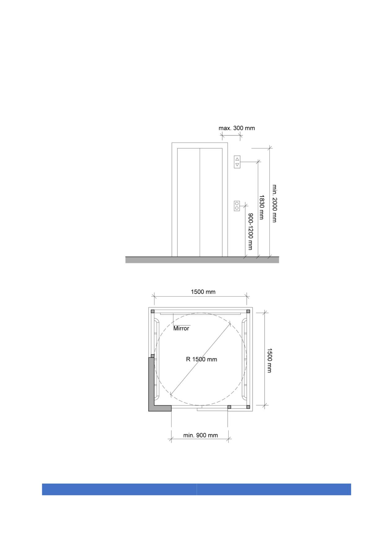
9. Braille and tactile signage shall be provided on the door jamb at a height of 1500
mm.
10. Audible signals shall sound when each floor is reached or an audible voice
announcement
Figure 26. Elevator recommended dimensions for interior dimensions and door
54
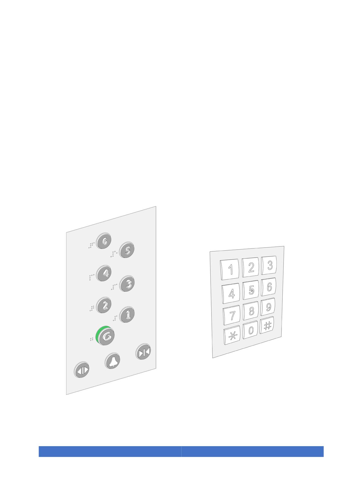
11. Buttons shall be located at a height between 900 mm and 1200 mm. They shall
present high-embossed European numerals. Braille numerals shall be located on the
left lower side of each button.
12. For elevators serving a large number of floors, a keypad shall be installed at a
maximum height of 1200 mm to ensure that all floors can be called.
13. The button to reach the exit floor (usually ground floor) shall be raised at least 3 mm
from the other buttons and be circled with a green line at least 2 mm wide.
14. Call buttons in each floor can contain icons instead of digits in tactile and colour
contrasted against the backg0round.
15. Buttons shall always provide a two-channel feedback when pressed: visual and
acoustic or visual and tactile. Touch buttons and touch screens are not permitted.
Figure 27. Example of buttons path
Figure 28. Example of a keypad with
raised dot in number 5 key
55
16. It must have a sign (graphic and tactile) indicating the phone number of the alarm
centre and the appropriate number to report an emergency.
17. To allow deaf users to communicate in an emergency the installation company must
guarantee one of the following options:
• A CCTV Intercom.
• A means of sending and receiving emergency SMS from inside the cab by
maintaining the necessary network coverage or through an alternative system.
18. Lights should be installed only on the ceiling to provide a uniform illumination of a
minimum of 100 lux.
19. In panoramic elevators a full height opaque wall or corner section of 800 mm wide
shall be provided.
20. Doors shall open automatically and shall remain opened at least 3 seconds.
21. If there is a user in the doorway, the door shall automatically reopen and shall not
produce a force greater than 135 N. Sensors should be at two levels to ensure that it
detects lower items.
22. Whenever there are various options of vertical circulation there shall be a sign
indicating the direction to the accessible elevator.
5.10.1. Lifts and lift platforms
A vertical lift platform must fulfil the following requirements:
1. The lift platform must have dimensions that allow its use by a wheelchair user.
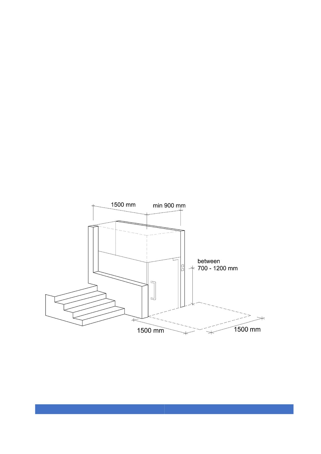
2. The surface of the platform has a free space of 900 mm x 1500 mm (width x length).
3. Access to the platform areas shall be free of obstacles in every landing of 1500 mm
x 1500 mm.
4. A lateral space of interaction in front of the lift-calling button shall be at a height
between 700 mm and 1200 mm.
5. The platform’s entrance or exit shall have minimum 900 mm width and be free of
obstacles.
6. It must have side protection separating users from the walls of the lift platform shaft.
56
7. Inside the platform cabin, at least two handrails shall be placed at a height of 900
mm ± 100 mm from the floor.
8. The control buttons design shall be accessible. They shall have a continuous
pressure button operation and shall be operable with the elbow.
9. There should be an additional external control for the platform that could be used by
authorized personnel when necessary.
10. If the cabin is open, with walls only reaching halfway up the cabin, the maximum
allowed travel height is 2000 mm in public buildings and 3000 mm in private
housing.
11. If the platform lift is a full cabin model the maximum allowed travel height is 4000
mm.
Figure 29. Lift platform dimensions
57
5.11. Escalators, travellators and mechanical ramps
Travellators are considered complementary elements of accessible pedestrian paths
and shall have the following requirements:
1. The moving surface shall present a maximum gradient of ≤5%.
2. The beginning and the end of travellators shall present a contrasting pavement with
the surroundings.
3. The direction of travel shall be marked.
4. It is recommended to install an audio system indicating the start and end of these
devices.
Escalators and mechanical ramps are not considered part of the accessible path.
Whenever provided they shall be accompanied by a non-mechanical accessible
alternative route or an elevator that leads to the different levels.
5.12. Doors
Doors connected to accessible paths must meet the following requirements:
1. Automatic doors are preferred for public building entrances and high pedestrian
traffic areas.
2. Doors should have a free passage width of minimum 900 mm. This free passage
must be measured between the face of the door and the face of the doorstop with
the door open at 90°.
3. Opening and closing mechanisms shall be placed between 900 mm and 1200 mm in
height and shall be easy to grasp and use. Pressure mechanisms or levers shall be
easy to operate with the elbow or be automatic.
58
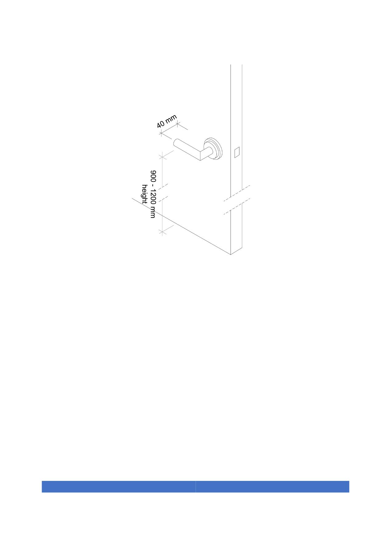
Figure 30. Door handle
4. If lever systems are provided, they must be separated from the door body by at least
40 mm.
5. Round knobs are not allowed.
6. For sliding doors, a vertical fixed bar shall be provided to open the door.
7. The opening space of a door shall not invade the manoeuvring spaces and the
accessible paths.
8. Doors shall be level.
9. The force required to open a door shall be a maximum of 25 N.
10. A swinging doors leaf shall be able to open at 90 °.
11. Doorstoppers shall be provided to prevent the door from hitting and damaging the
wall.
59
12. Where there are two or more door leaves at least one of the leaves of the door must
be able to be considered an accessible door according to the above specifications.
13. In high use areas kick plates of at least 250 mm high are recommended.
14. If there is a revolving door, an alternative door shall be provided.
5.12.1. Manoeuvring spaces at doors
One-way swinging doors shall have a manoeuvring clear space on both sides.
The dimensions of these spaces shall fulfil the following requirements:
1. On the pull side, a minimum space of 600 mm adjacent to the leading edge of the
door with a minimum clear floor space of 1500 mm x 1500 mm shall be provided.
2. On the push side, a minimum space of 300 mm adjacent to the leading edge of the
door with a minimum clear floor space of 1200 mm x 1200 mm shall be provided.
3. In sliding doors, a minimum space of 300 mm adjacent to the leading edge of the
door with a minimum clear floor space of 1200 mm x 1200 mm in both sides shall be
provided.
4. Clear floor space shall not be obstructed by other swinging doors and they shall be
free of obstacles.
60
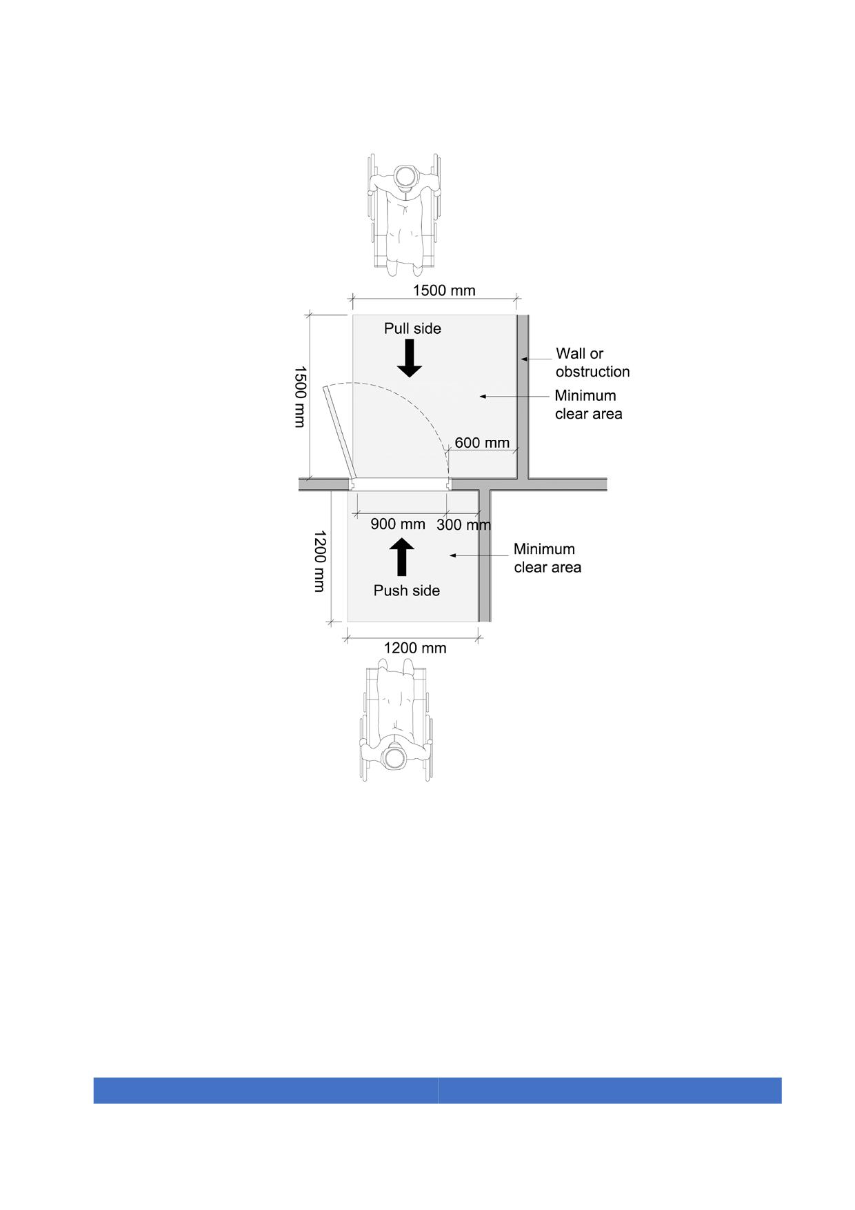
Figure 31. Minimum manoeuvring space in front of one push side swinging doors
61

Figure 32. Minimum manoeuvring spaces in front of both-side push swinging doors and
sliding doors
5.12.2.
Two doors in a series
When two doors are installed in a series, they shall have a minimum space of 1200 mm
between them plus the width of the door swinging into that space.
62
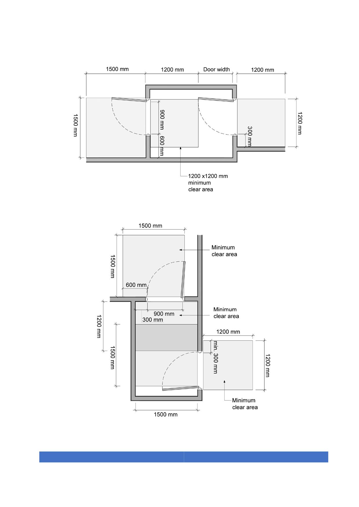
Figure 33. Minimum manoeuvring space for two aligned doors in a series
Figure 34. Minimum manoeuvring space for two angled doors in a series
63
5.13. Power-assisted doors
A motion detector or a floor-pad sensor and one that is manually activated by pushing a
control can automatically activate power-assisted doors.
Automatic doors are preferable, being sliding doors they are most convenient to use
and do not require guardrails for door-swing protection.
Power-assisted swinging doors shall:
• Take 3 s or more to move from a closed to a fully open position;
• Remain fully open for a minimum of 5 s;
• Require a force of not more than 66 N to stop door movement.
5.14. Windows and window hardware
Windows and window hardware shall fulfil the following requirements:
1. Opening windows either in facades, internal or external corridors, shall not project
into pedestrian areas below a height of 2200 mm.
2. Pressure mechanisms or levers shall not require wrist turning, and should be easy to
manipulate with one hand, elbow or automatically operated.
3. Whenever possible, prioritize natural light and air.
4. In order to provide exterior vision to children people with short stature and
wheelchair users the glazing should be no higher than 900 mm from the floor.
Guardrail protection shall be provided if windows can be opened lower than 1200
mm in order to prevent falls.
64
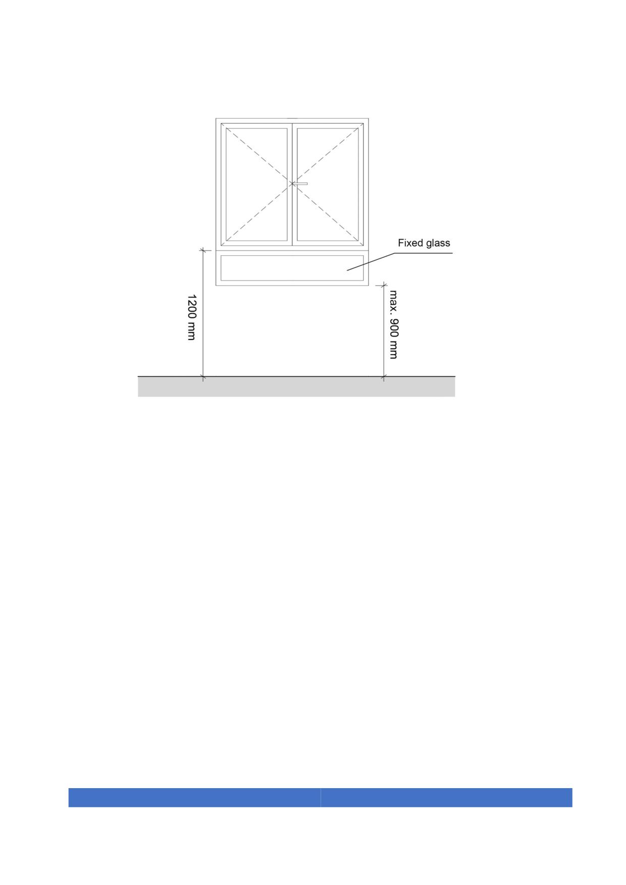
Figure 35. Window at 1200 mm with fixed glass at 900 mm from the floor
5.15. Switches
Switch controls and electric outlets shall be installed between 900 mm and 1200 mm
height and be located a minimum of 600mm from any corner.
The switch plate shall present at least a contrast of 30 points LRV in relation with the
surrounding wall.
It shall be possible to activate it with an elbow.
5.16. Glass surfaces
All glass surfaces that could be confused with doors or openings, as well as the glass
doors that do not have elements that can be identified, such as frames or handles, shall
contain visual elements that guarantee its detection.
The marks shall consist of two horizontal bands, each at least 100 mm high, and shall
have a reflectance contrast with the glass backg0round of at least 30 points LRV (Light
Reflectance Value).
65
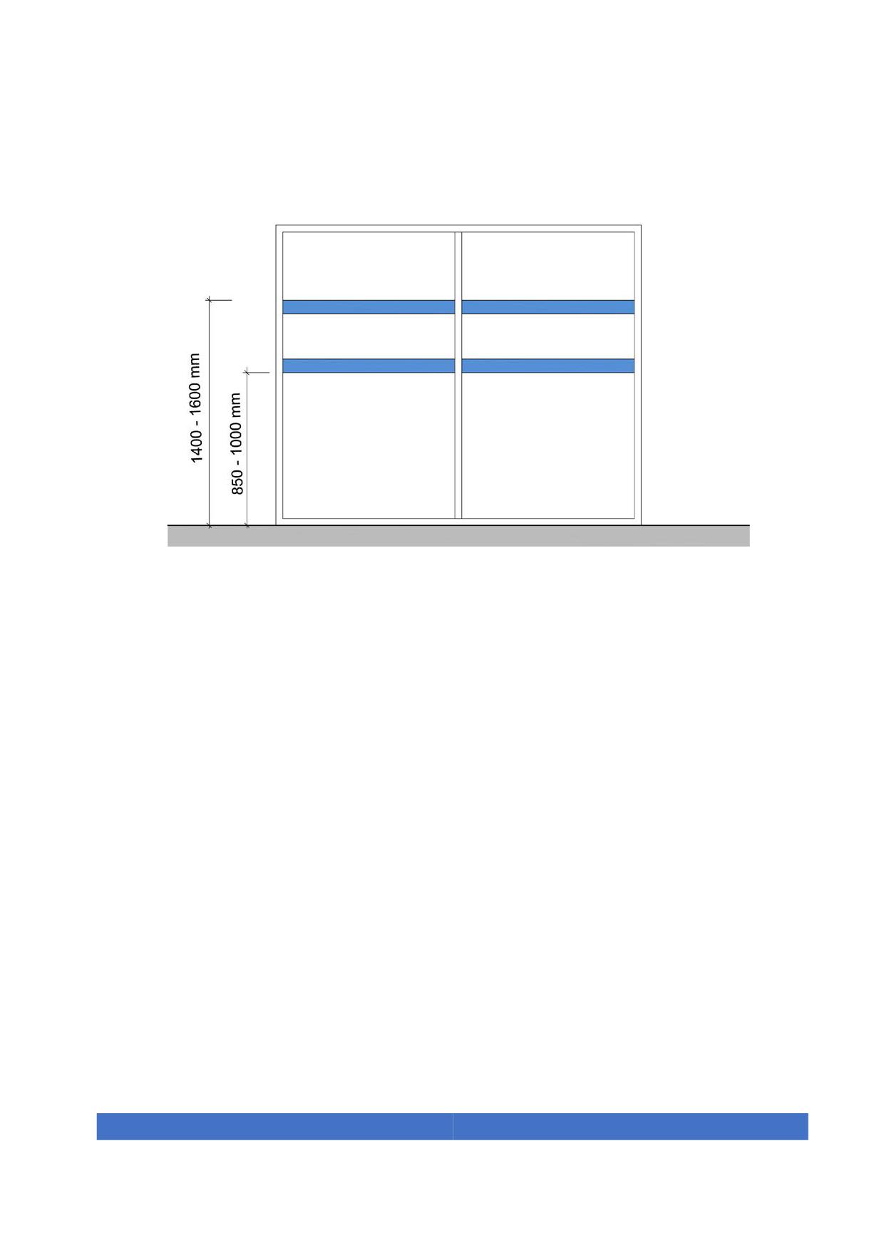
The upper band shall be affixed at a height between 1400 mm and 1600 mm and the
lower band affixed at a height between 850 mm and 1000 mm above the floor.
Figure 36. Glass marks
It is not necessary to mark the glass surfaces with contrasted bands in the following
cases:
1. In glass surfaces of less than 500 mm in width.
2. The highest point of the glass surface is less than 850 mm.
3. If it has other opaque elements between 850 mm and 1700 mm occupying its entire
width.
4. If it has other types of marks (logo, artistic illustrations, etc.) that occupy 50% of the
area between 850 mm and 1700 mm without empty spaces bigger than 500 mm
wide.
5. Glass surfaces with fixed elements in front of it that block the entire approaching
space.
5.17. Accessible toilets
All public facilities and new public mobile or fixed toilets installed in parks, gardens,
squares, streets, exhibitions, fairs, concerts, and in outdoor public spaces and buildings
for public use shall have at least one accessible toilet for each gender and in every bank
66
of toilets, or 1 toilets for male and females within a 150 meters distance from any part of
the building.
If only one toilet for each gender is provided, then it must be accessible. Accessible
toilets shall fulfil the following requirements:
1. The door should have a clear width of 900 mm and comply with Doors section of this
Code.
2. Furniture shall have a reflectance contrast with the walls of at least 30 points LRV
(Light Reflectance Value).
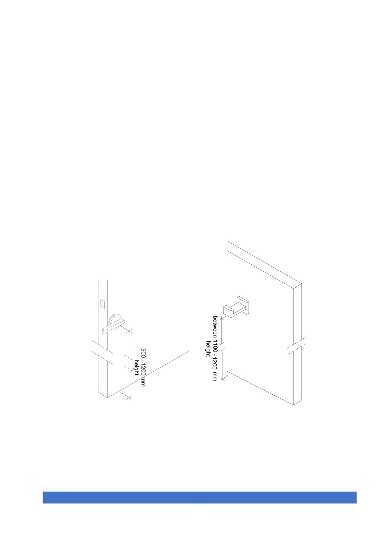
3. Every cabin door shall be provided with a latch operable with the elbow installed
between 900 and 1200 mm and a coat hanger installed between 1100 and 1200
mm.
4. Each toilet block for both genders shall include a baby changing table duly marked.
Figure 37. Cabin latch example
Figure 38. Door hanger
5.18. Urinals
At least one accessible urinal shall be provided wherever urinals are located.
Urinals that reach the floor and therefore are designed for all male heights are
67
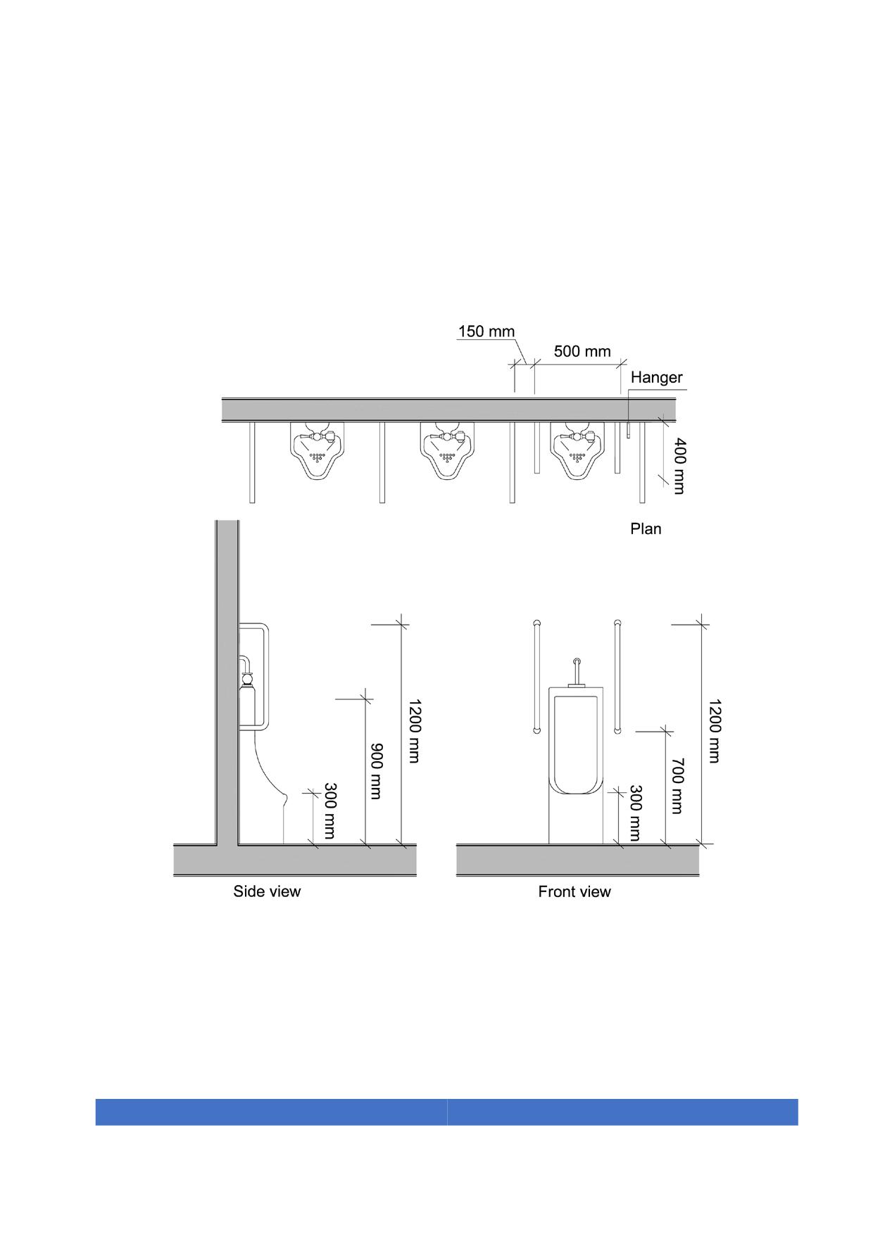
preferred. The bottom lip should be at a maximum height of 300 mm.
Grab bars shall be provided on both sides of the urinal mounted vertically with the
centreline at 1000 mm high and 380 - 450 mm from the centreline of the urinal.
Where privacy screens are provided there should be a clearance of 920 mm.
Figure 39. Urinal dimensions and grab bars
5.18.1.
Floor surfaces
Public toilet shall have non-slippery floor surfaces.
68
Pendulum Test Value (PTV) must be greater than 45 and shall fulfil the requirements of
section 5.2. Pendulum technique must consider both shoed and barefoot users.
5.18.2.
Sinks
Sinks shall meet the following requirements:
1. Sinks shall not be the pedestal type and shall have clear knee space below.
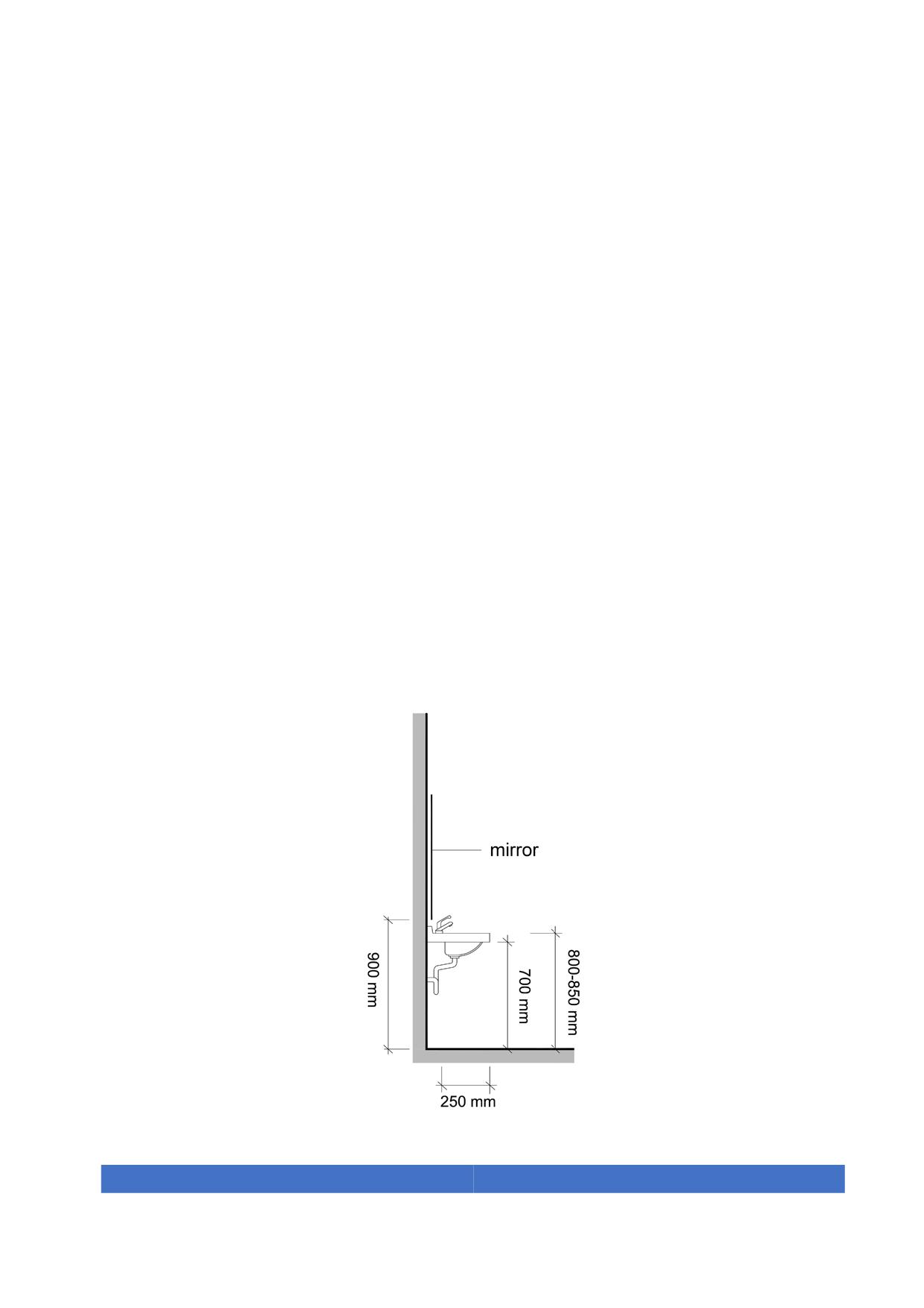
Dimensions of this clearance space are minimum 700 mm high and 250 mm deep,
from the faucet to the edge. The usable surface height shall be between 800 mm
and 850 mm.
2. When sinks are in a row at least one shall be possible to use with all the
accessories.
3. Faucets shall be operated by pressure with a lever handle or with a sensor. Turning
or pressure systems that require great effort to be operated are not allowed.
4. The distance from the sink edge to the faucet shall be less than 600 mm and its
height from the floor shall be between 900 mm and 1200 mm. The lower edge of the
mirror shall be mounted at a 900 mm height or less.
5. The pipes under the sink should be recessed.
Figure 40. Dimensions for sinks
69
5.18.3.
Controls and accessories
All controls and accessories shall meet the following requirements:
1. Flushing systems are operated by pressure or with a flush handle. Controls shall
have a large surface and are operable with only one hand or elbow.
2. Controls and accessories such as soap dispensers or dryers among others, shall be
mounted at a height between 700 mm and 1200 mm.
5.19. Accessible toilet stalls
Accessible toilet stalls can be located both inside the toilet blocks provided for each
gender or outside the blocks. Family toilets should be located outside of the block of
toilets. According to the tables of Annex 2 this is only allowed in certain types of
buildings.
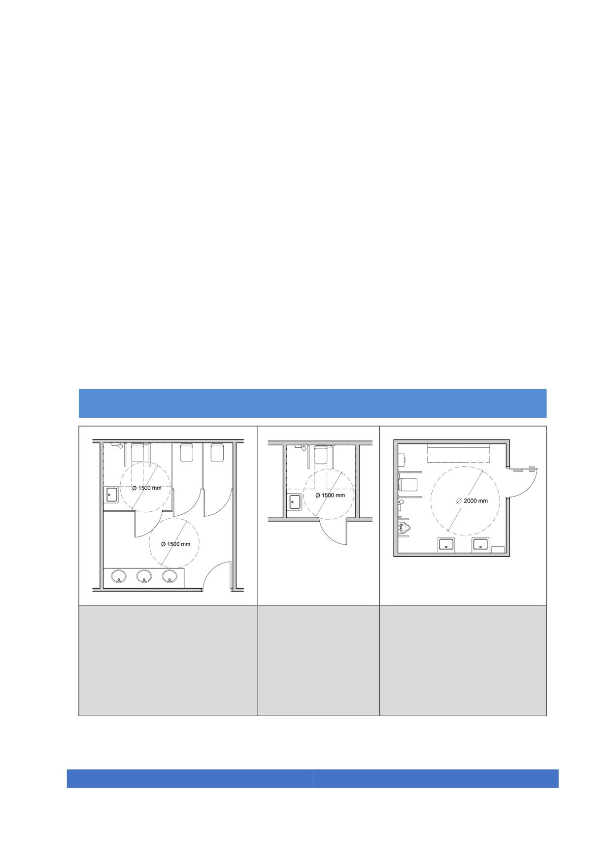
Types of toilets
Accessible toilet within a toilet
Detached
Full Family Toilet
block
accessible toilet
that can be used as
family toilet in
certain building
types
Table 6. Types of toilets
70
The number of accessible toilets shall follow the table 7.
NUMBER OF ACCESSIBLE TOILETS
Use of the Building,
Minimum Number of Toilets
establishment or area
Any public use
1 Accessible toilets for each gender should be
provided in every floor being at least 10% of the
total number of toilets in every block or 1
independent accessible toilet for both genders
1 accessible toilet within a 150 meters distance
from any part of the building
Table 7. Number of Accessible Toilets
The following table indicates the minimum dimensional parameters required for
accessible toilets:
Minimum dimensions for accessible toilets
Dimensions of circulation spaces
Corridor widths in toilets, showers, lockers spaces, etc.
1200 mm
Manoeuvring turning space diameter
1500 mm
Accessible toilets and cubicles conditions
Manoeuvring space diameter between 0 and 700 mm height
1500 mm
free of obstacles
Lateral interaction space
On both sides
Table 8. Minimum dimensional parameters for accessible toilets
71
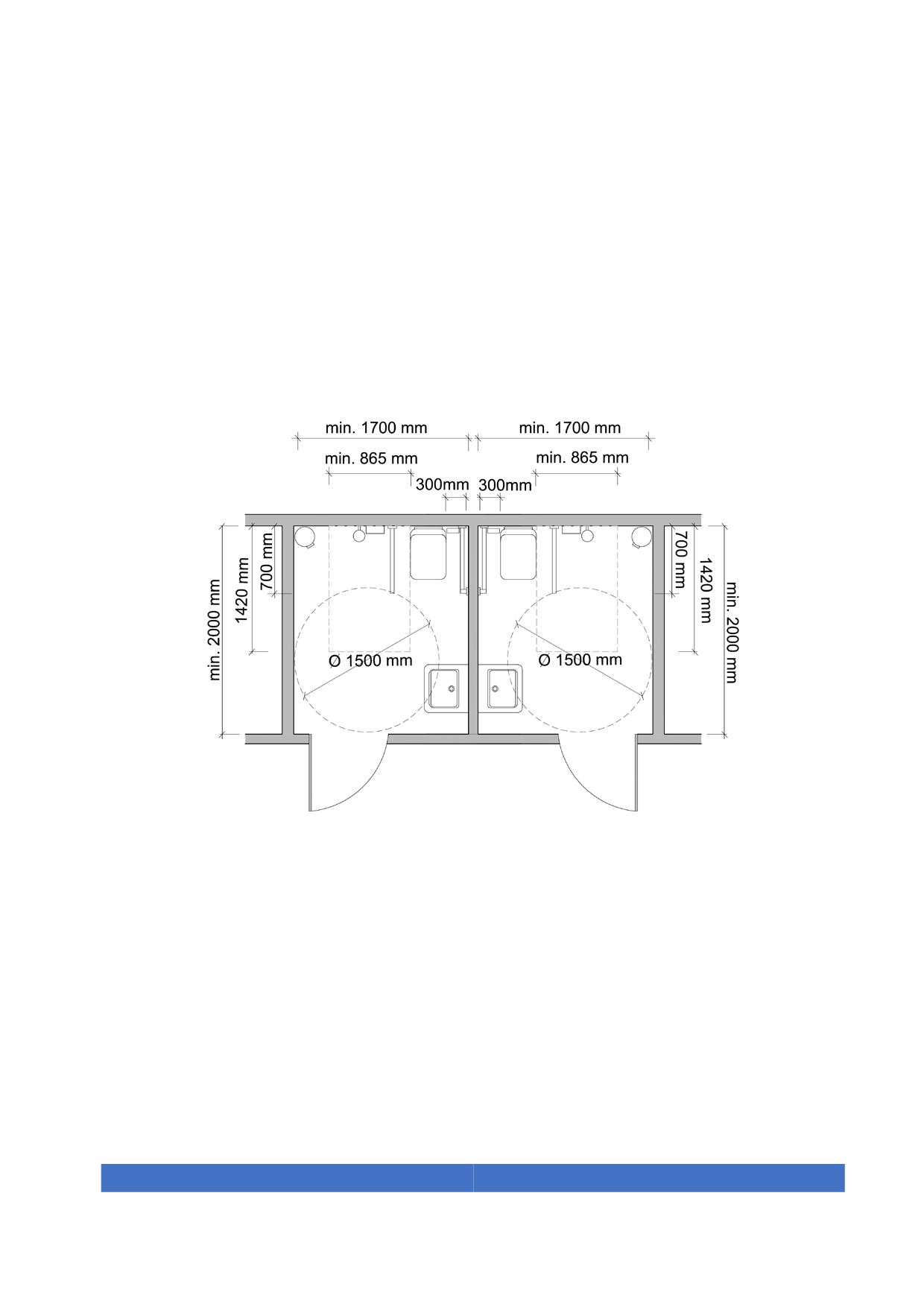
Accessible toilets shall fulfil the following requirements:
1. There is a lateral interaction area on both sides of the toilet and beside the shower if
one is provided. The requirement of lateral transfer space on both sides of the toilet
in accessible restrooms can be substituted by only one if in the same block there are
symmetrical units.
2. Shall provide grab bars as describe in section 5.17.2.
3. A changing table shall be provided in all accessible toilet rooms.
Figure 41. Symmetrical toilets may substitute interaction space on both sides
5.19.1. Doors
Doors must meet the following requirements:
1. Fulfil the door criteria set out in section 5.12.
2. Open outwards or be sliding.
3. A horizontal handle bar with a length of 300 mm shall be placed at a height between
900 mm and 1000 mm at 300 mm from the hinge side on the inside of the door and
by the latch side on the outside of the door.
72
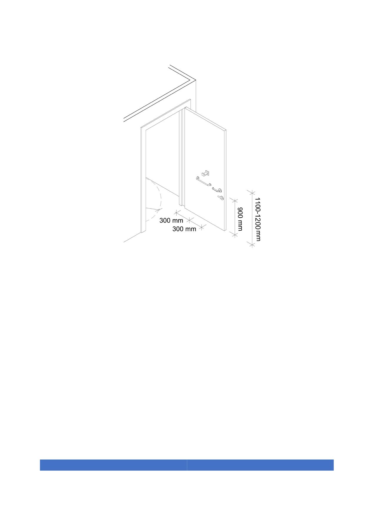
Figure 42. Required toilet door accessories
4. It shall be possible to use the door latch with an elbow.
5. It shall include a coat hanger installed between 1100 mm and 1200 mm.
5.19.2. Grab bars for toilet seats
Grab bars shall meet the following requirements:
1. Grab bars are stable and are separated from the wall a minimum of 45 mm. It must
withstand a force of 1 kN in any direction and have a circular diameter between 30
mm and 40 mm.
2. The transfer horizontal grab bars are mounted at a height between 700 mm and 750
mm and have a support length of 700 mm. The bars mounted in the transfer space
must be foldable.
3. The distance between both grab bars installed on both sides of the toilet shall be
between 670 mm and 700 mm.
4. The toilet seat height shall be located between 450 mm and 500 mm.
73
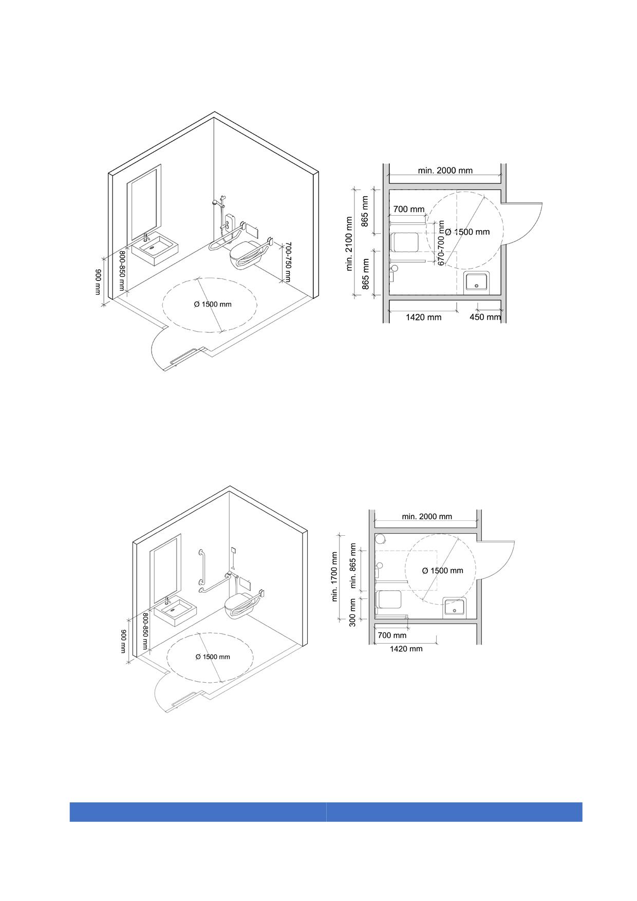
Figure 43. Transfer area on both sides of the toilet
5. In case of toilets with only one transfer area, a horizontal bar shall be mounted at
300 mm from the sanitary toilet edge with a minimum length of 700 mm and are
mounted between 700 mm and 750 mm from floor level.
Figure 44. Minimal dimensions for toilets with only one interaction area when permitted
74
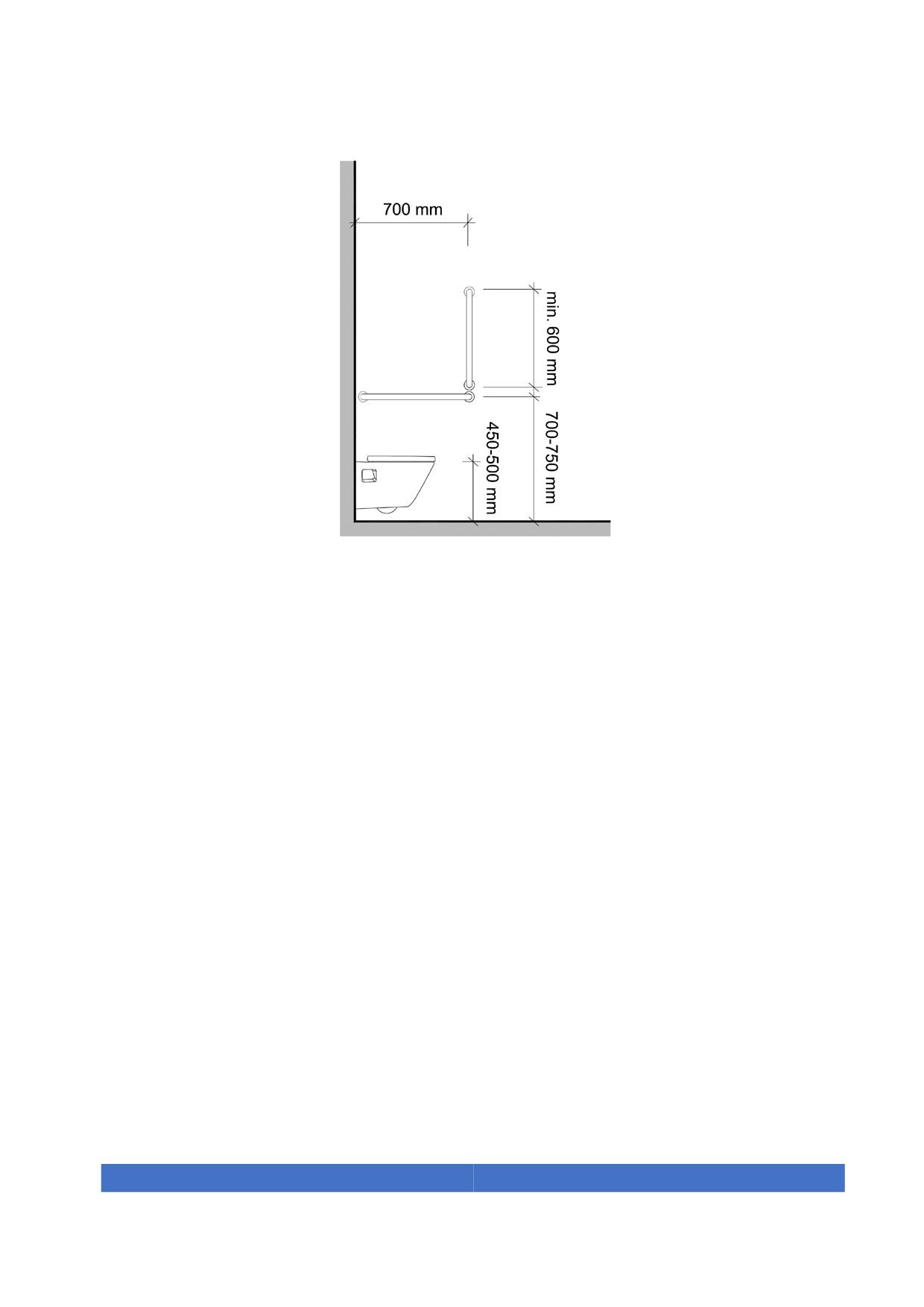
Figure 45. Fixed bars positions
6. An additional vertical bar with the dimensions of the above drawing shall also be
installed.
5.20. Accessible showers
Where showers are provided, at least one shall be accessible
Showers shall meet the following requirements:
1. The shower floor surface shall be flush with the level of the surrounding area. The
maximum slope for water evacuation is 4%.
2. If a shower is provided it shall have a minimum dimension of 865 mm x 1200 mm
and have a seat of at least 400 mm x 400 mm. This seat shall be located at a height
between 450mm and 500 mm from the floor and be separated from the wall between
150 mm and 200 mm. The seat shall be free of sharp edges. Adjustable height
seats are preferred; especially in hotels and residences.
3. Accessible showers shall have a horizontal grab bar to assist in transferring and a
vertical one for support. The horizontal bar shall have a length of 800 mm and be
mounted at a height of 700 mm to 750 mm from the floor level in the wall beside the
shower seat. The vertical bar with a length of 800 mm shall be installed in the lateral
75
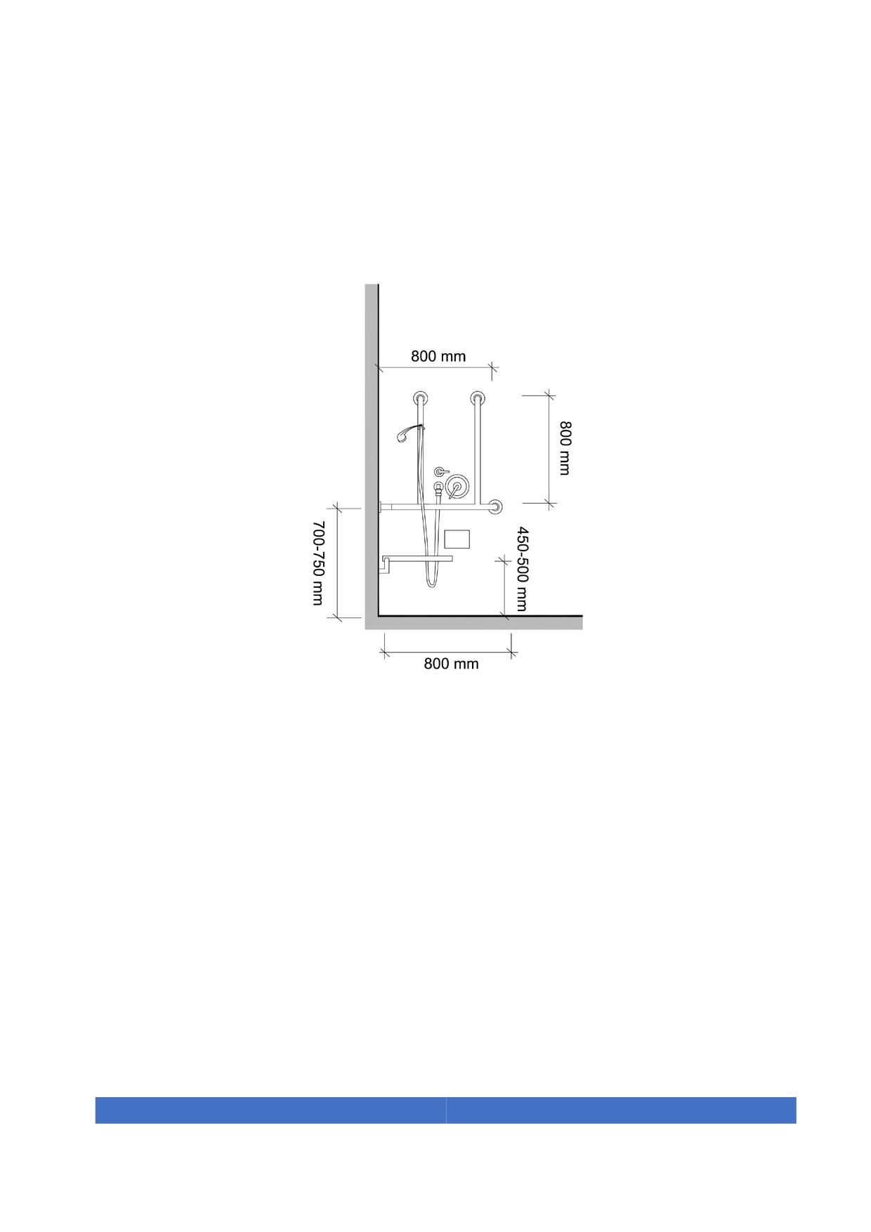
wall of the shower seat at a height of 800 mm. The distance between both bars
installed on both sides of the shower seat shall be between 670 mm and 700 mm.
4. Alternative systems such as bath chairs with the same features can be provided.
5. Controls should be within 500 mm of the seat.
Figure 46. Bars dimensions in showers
5.21. Family toilets
It is recommended 1 family toilet for each block of toilets. At least 1 family toilet within
300 m distance from any part of the building shall be provided.
5.21.1. Full Family toilets
Full family toilets shall be provided in:
• Shopping malls
• Amusement parks and theme parks
• Leisure centres
• Airports
76
A full family toilet is considered accessible when it meets the requirements specified for
accessible toilets and following these specifications:
1. Has a folding adult changing board for adults without interfering with any of the
approaching manoeuvring and transfer spaces to the toilet and the sink. The board
usable area shall be at a height of 500 mm from the floor.
2. It provides a second sink at a height of 500 mm from the floor.
3. There is a clear manoeuvring turning space of at least 2000 mm diameter free of
obstacles.
4. In addition to the toilet, a urinal shall be provided with a usable height of 400 mm.
5. An emergency call button shall be provided.
77
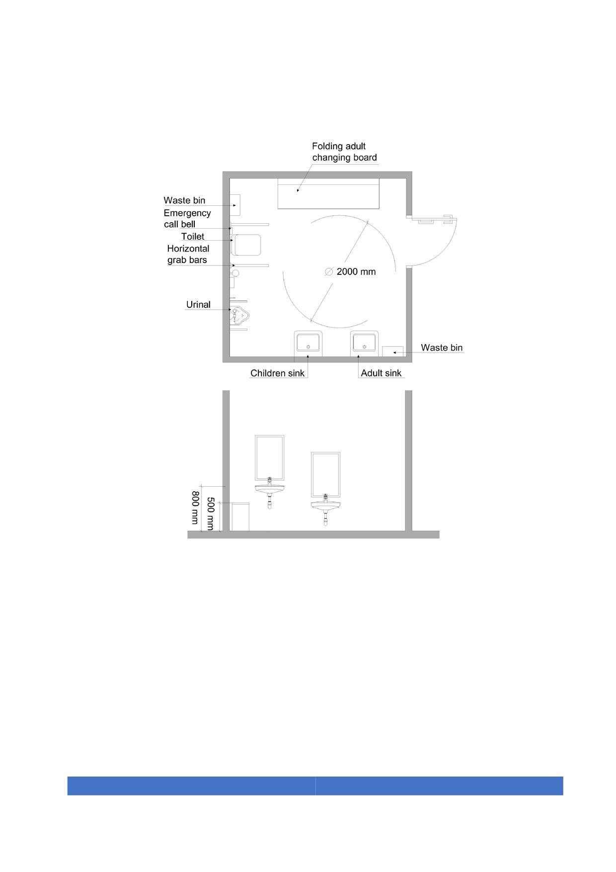
Figure 47. Example of full family restroom
5.22. Feeding rooms
Feeding rooms shall be provided in:
• Shopping malls
• Amusement parks and theme parks
• Leisure centres
• Airports
78
It is recommended that 1 feeding room be provided for each block of toilets. At least 1
feeding room within 300 m distance from any part of the building shall be provided.
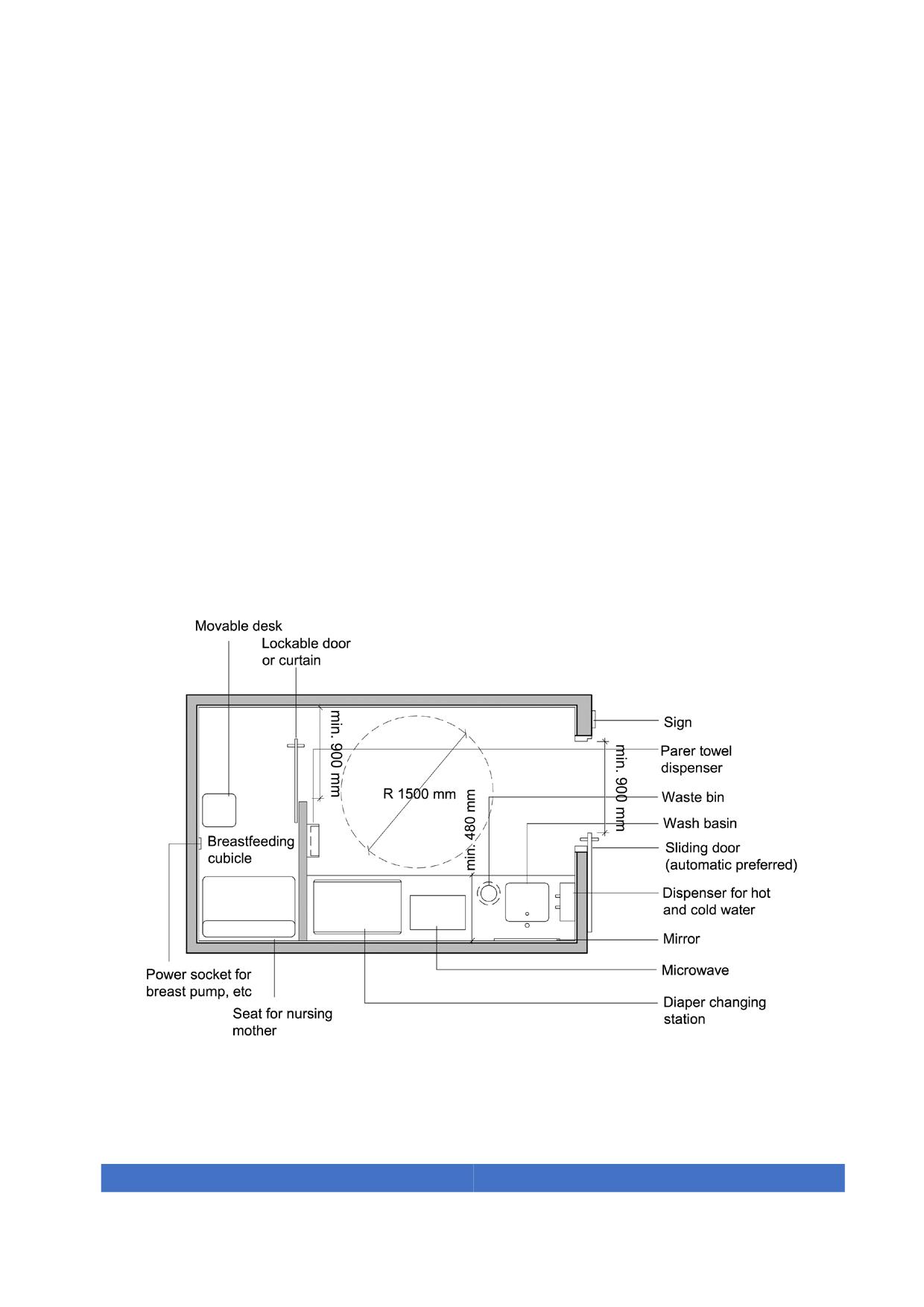
A feeding room shall meet the following requirements:
1. Its surface shall be at least 7 sq. meters for individual feeding rooms and 10 sq.
meters for dual feeding rooms.
2. Its design has to ensure an ease of movement with a pram and a child on the arms.
3. It shall have proper ventilation for any smell generated by the diaper waste bins as
well as proper place for the diaper waste bins.
4. Furniture shall have a reflectance contrast with the walls of at least 30 points LRV
(Light Reflectance Value).
All elements and appliances described in the drawing shall be provided although not
necessarily with the same distribution.
Figure 48. Example of individual feeding room - plan
79
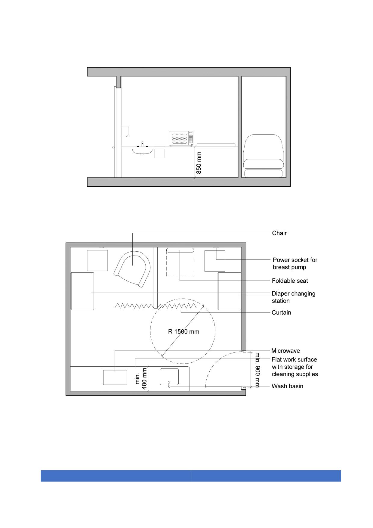
Figure 49. Example of individual feeding room - front view
Figure 50. Example of dual feeding room - plan
80
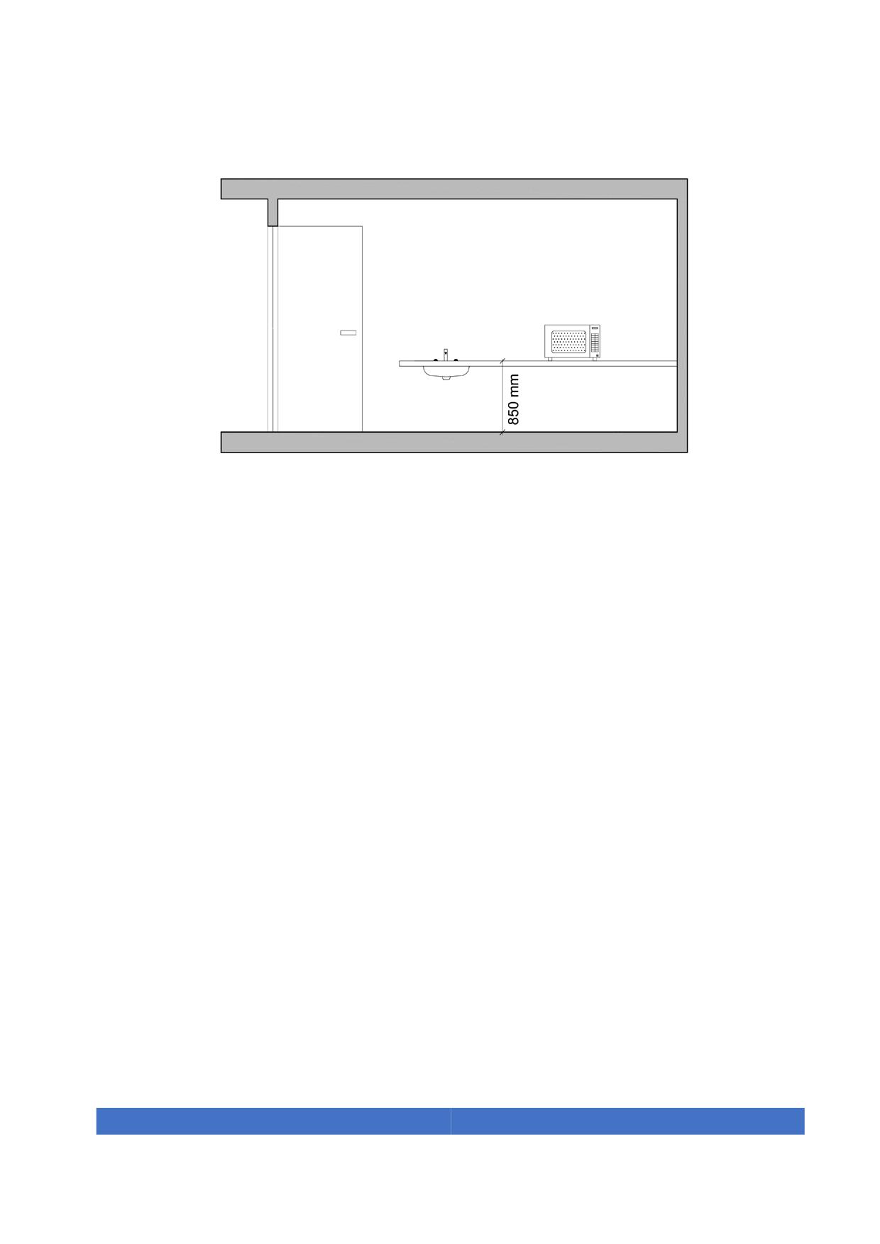
Figure 51. Example of dual feeding room - front view
5.23. Ablution areas
At least one accessible ablution unit shall be available in each ablution room.
Electronic or sensor faucets shall be installed in ablution areas to facilitate its use and to
reduce water waste.
In addition to the dimensions and characteristics of the accessible sink described in
section 5.17, ablution units shall meet the following requirements:
1. It shall be linked to an accessible path and shall be the closest to the entrance door.
2. Two horizontal grab bars, one in each side of the sink, shall be mounted at a height
between 700 mm and 800 mm and have a support length, equal to the length of the
sink.
3. A bidet shower system, soap and paper dispensers shall be mounted near the sink.
All accessories of toilets, including the bidet shower should be mounted at a height
between 700 mm and 1200 mm.
4. An approaching free space of 1200 mm width shall be provided. The pavement of
this interaction space shall have a reflectance contrast with the surrounding
pavement of at least 30 points LRV (Light Reflectance Value).
81
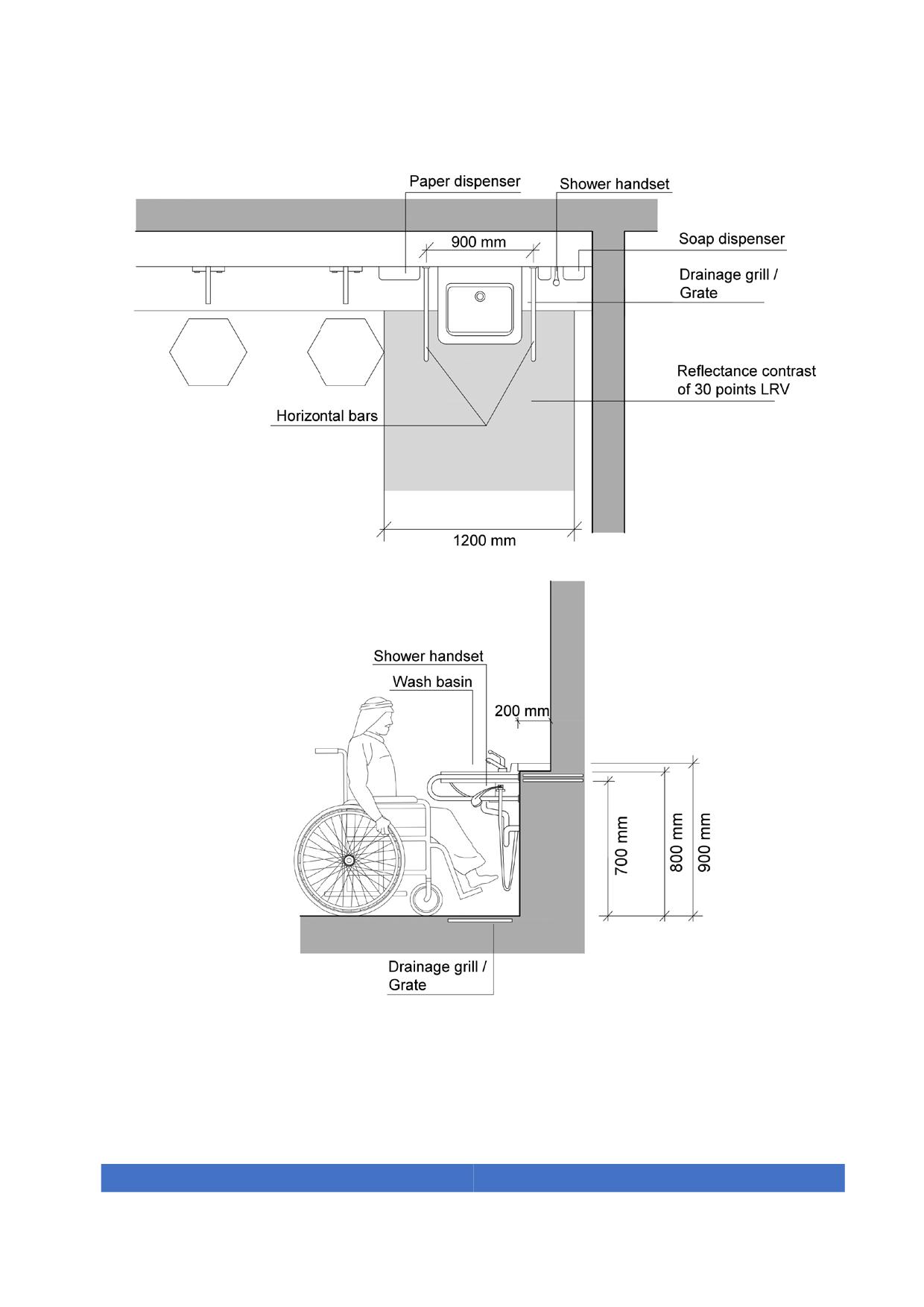
Figure 52. Free area and sink and accessories dimensions in ablution rooms
82
5.24. Furniture and other equipment
All furniture shall avoid sharp edges, protruding objects or burning surfaces and shall be
visually contrasted with their backg0round.
For surfaces that shall be touched, materials that retain heat from sun radiation shall be
avoided.
Furniture shall be made with non-toxic material.
All accessible furniture shall be connected to an accessible path.
5.24.1. Tables
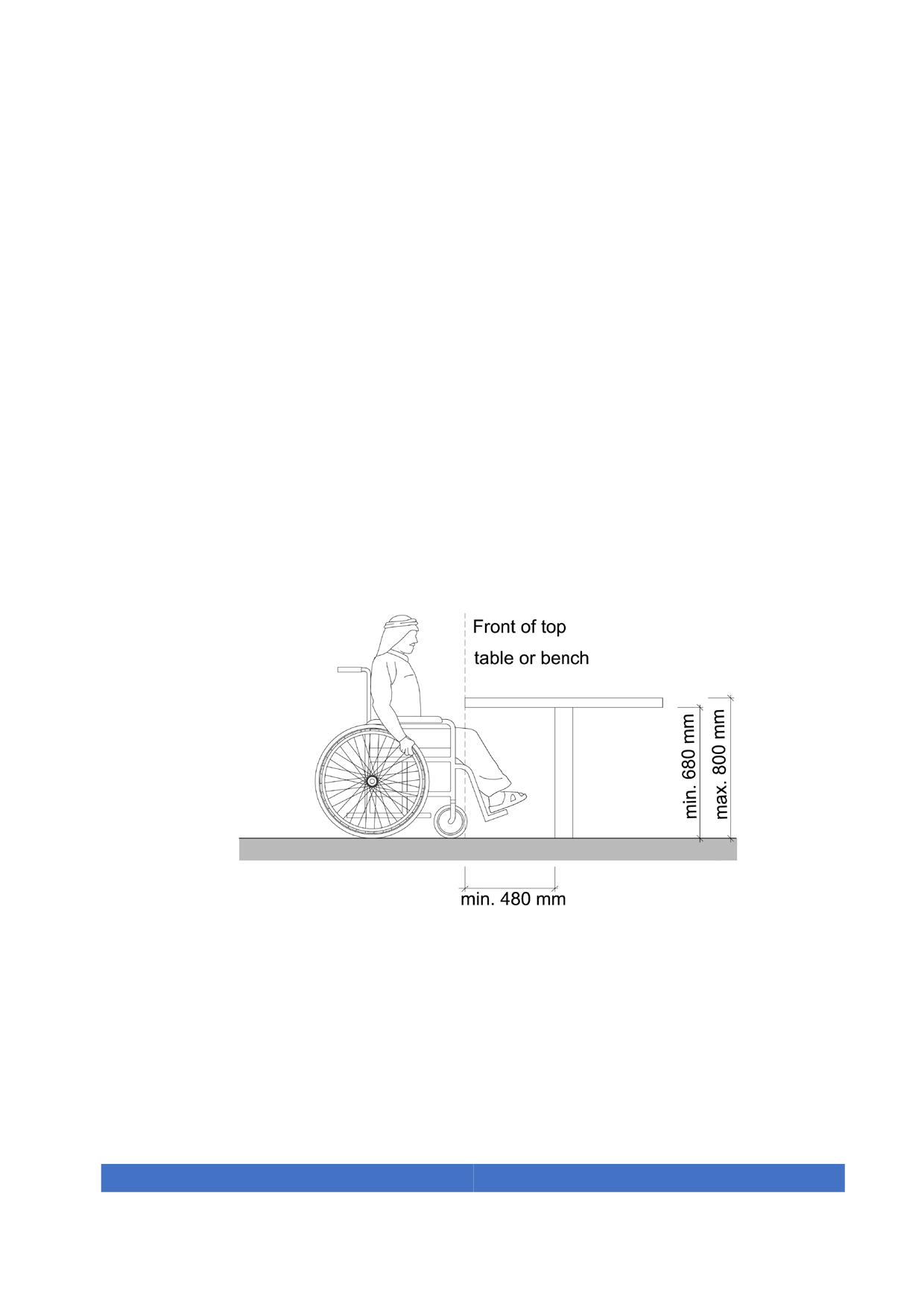
Tables shall fulfil the following requirements:
1. Tables shall not be higher than 800 mm with have a minimum clear room for leg
space of 680 mm high and 480 mm deep.
Figure 53. Table dimensions
2. Tables with integrated seats should be avoided.
83
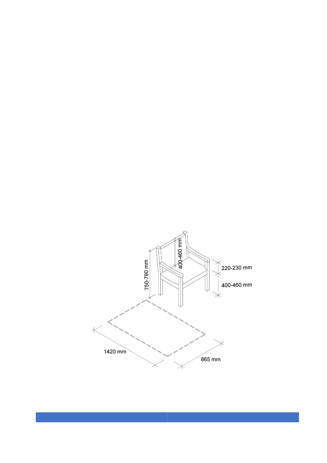
5.24.2. Chairs and Benches
Accessible chairs and benches must fulfil the following requirements:
1. The seat height shall be 430 mm with a ± 30 mm tolerance.
2. The seat depth shall be between 400 mm and 450 mm.
3. It has a backrest and its height shall be between 400 mm and 460 mm.
4. Some seats should have armrests.
5. It has on one side a lateral interaction space out of the accessible path.
Given the diversity and dispersion of users, it is recommended to provide furniture with
standing support, in combination with benches of varied height.
In urban spaces and parks benches shall be places at least every 100 meters while in
big buildings like shopping malls or airports benches or other seat types shall be
provided every 50 meters.
Figure. 54. Chair dimensions
84
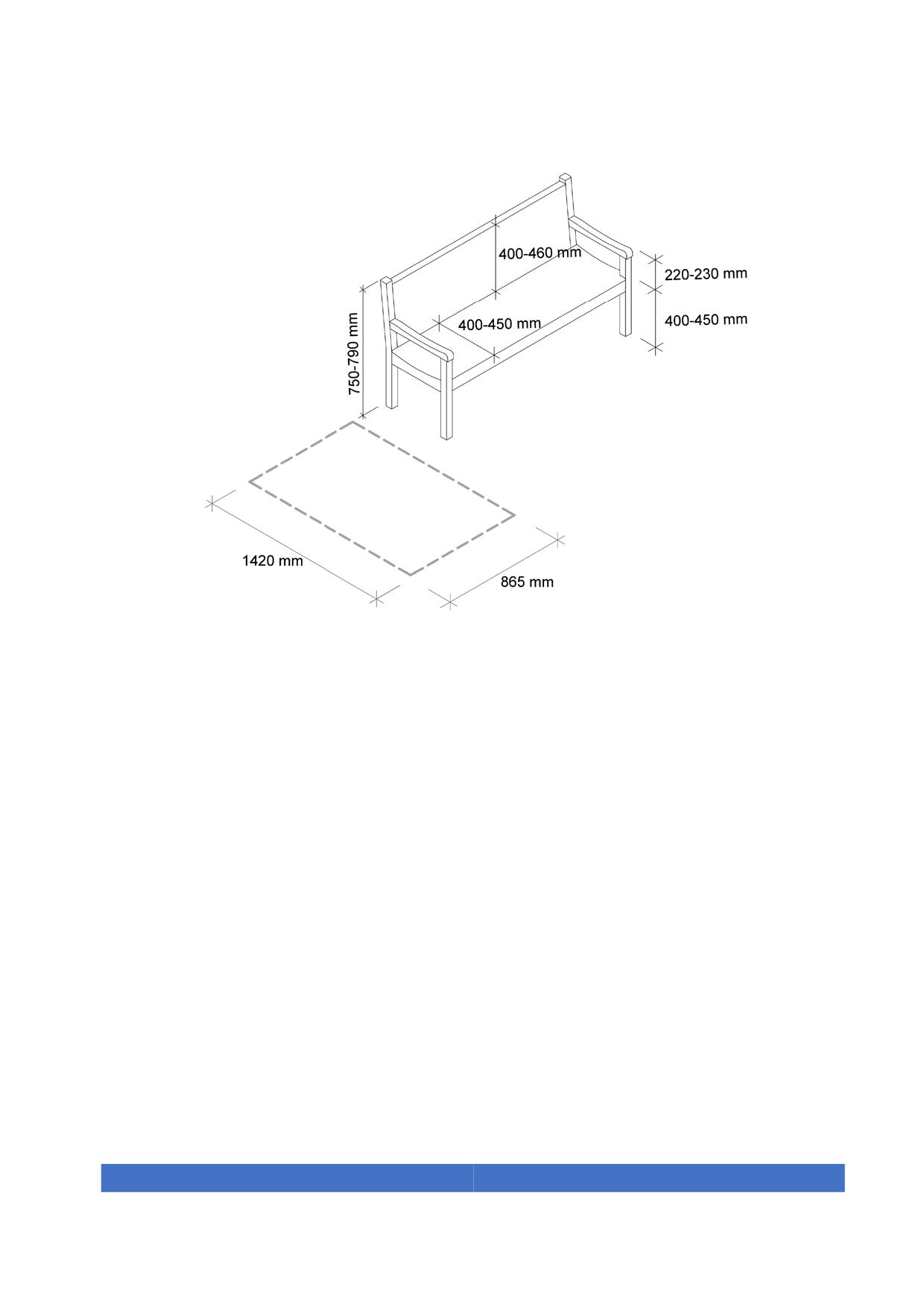
Figure 55. Bench with lateral interaction area
5.24.3. Drinking fountains
Drinking fountains in urban spaces and buildings must meet the following requirements:
1. Two fountains with different heights shall be provided, one no higher than 915 mm
above the floor for the accessible unit.
2. Drinking fountains shall allow its use through frontal approach.
3. If the push button is manual, it shall be at a height of between 700 mm and 1200 mm
and have an accessible mechanism that is easy to operate.
4. Water should be attainable at a height of between 600 mm and 850 mm ± 50 mm,
and near to the approaching space. The design has to prevent the user from getting
wet during use.
5. Drinking fountains should provide bottle fillers.
6. Drinking fountains should be located in an alcove where possible to ensure that it is
not a protrusion hazard.
85
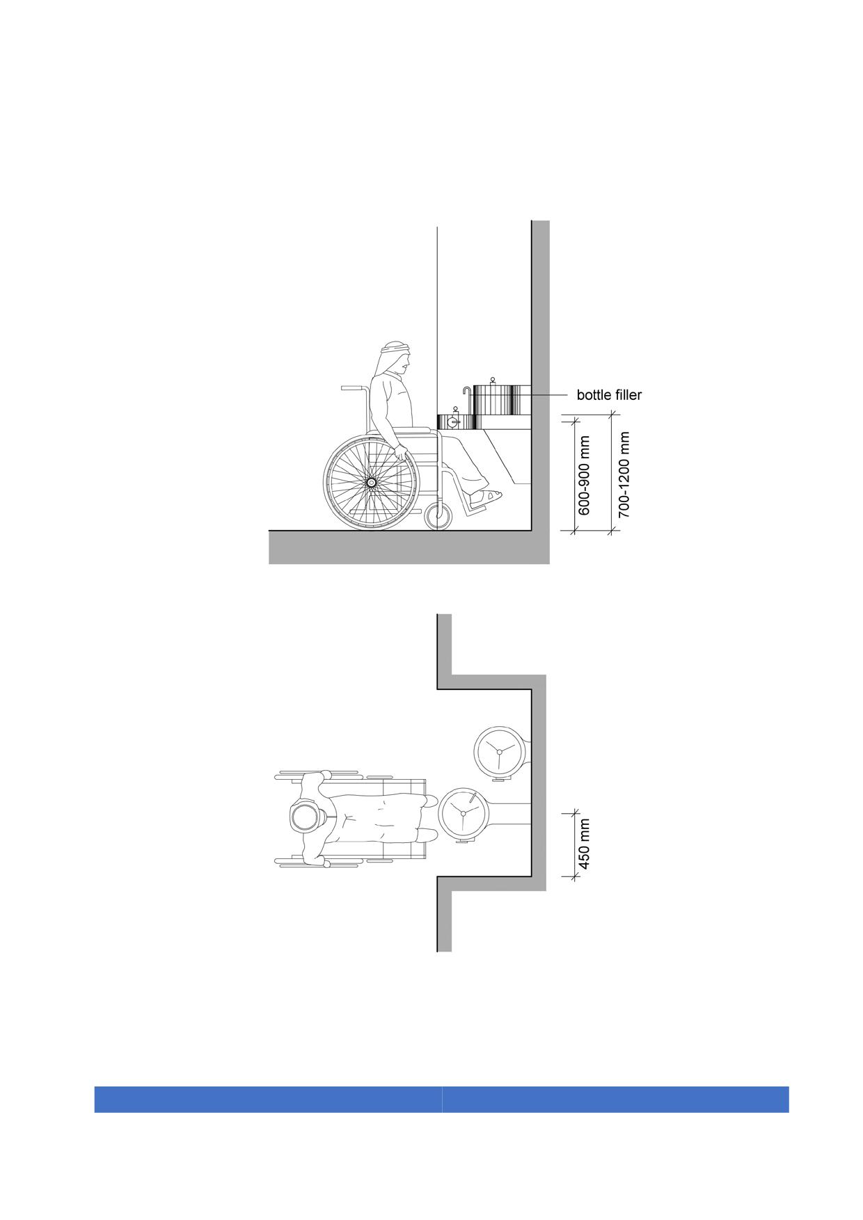
7. Drinking fountains should be installed against a contrasting backg0round to increase
visibility.
Figure 56. Drinking fountain dimensions
86
5.24.4. Trash bins
Accessible trash bins shall meet the following criteria:
1. They shall be located outside of the accessible path.
2. They shall have a lateral space of interaction. This space can overlay the associated
path.
3. Whenever possible it be located besides pedestrian crossings.
4. The trash bin opening shall be placed at a maximum height of 900 mm.
5. Trash bins shall be distributed in the space in a way that any person can find a trash
bin in 50 meters around.
6. Opening mechanisms shall be operable with an elbow.
7. Signage shall be well contrasted.
87
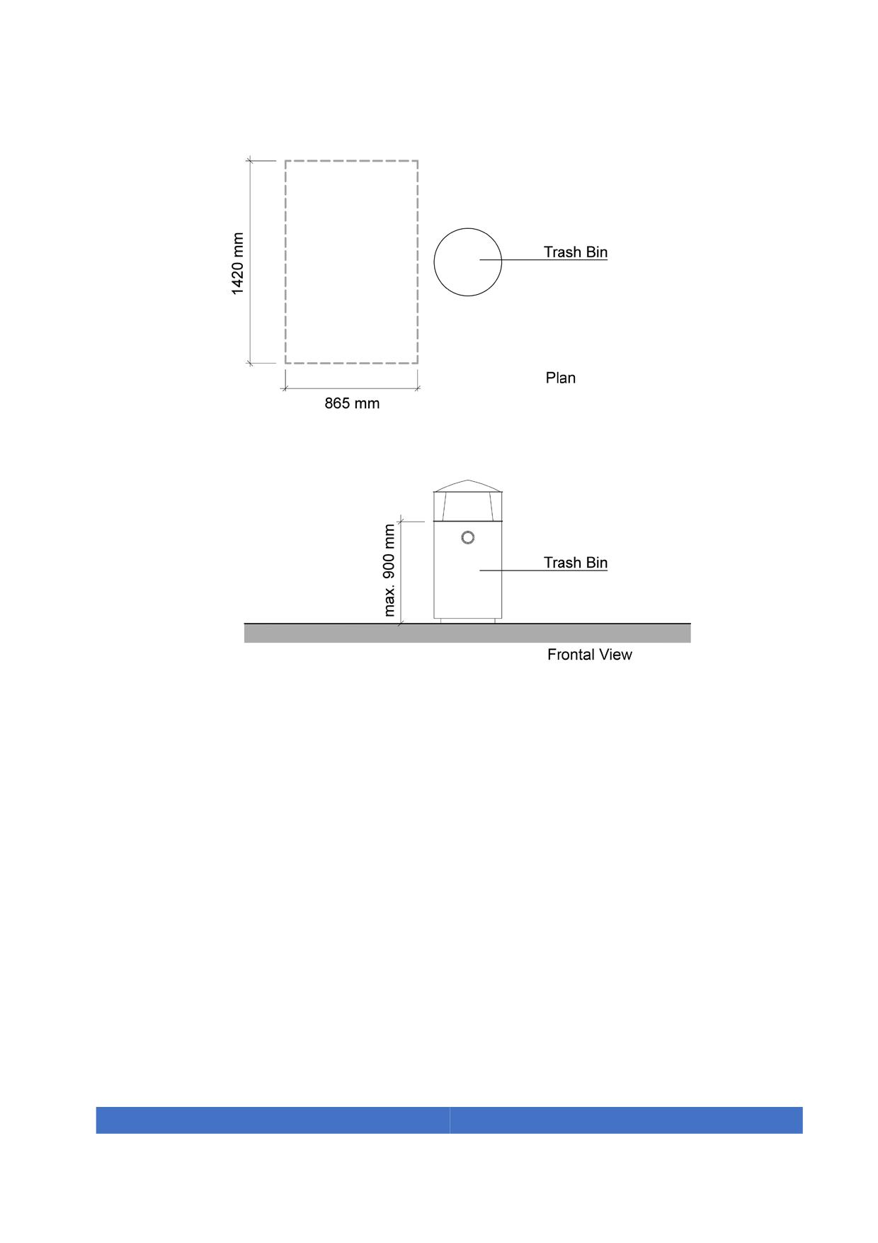
Figure 57. Example of a trash bin
5.24.5. Vending machines and ATM’s
Vending machines and ATMs are considered accessible when they fulfil the following
conditions:
1. There is at least one frontal or lateral interaction space ensuring privacy. The floor
surface is smooth and non-slippery with a gradient of no more than 2%.
88
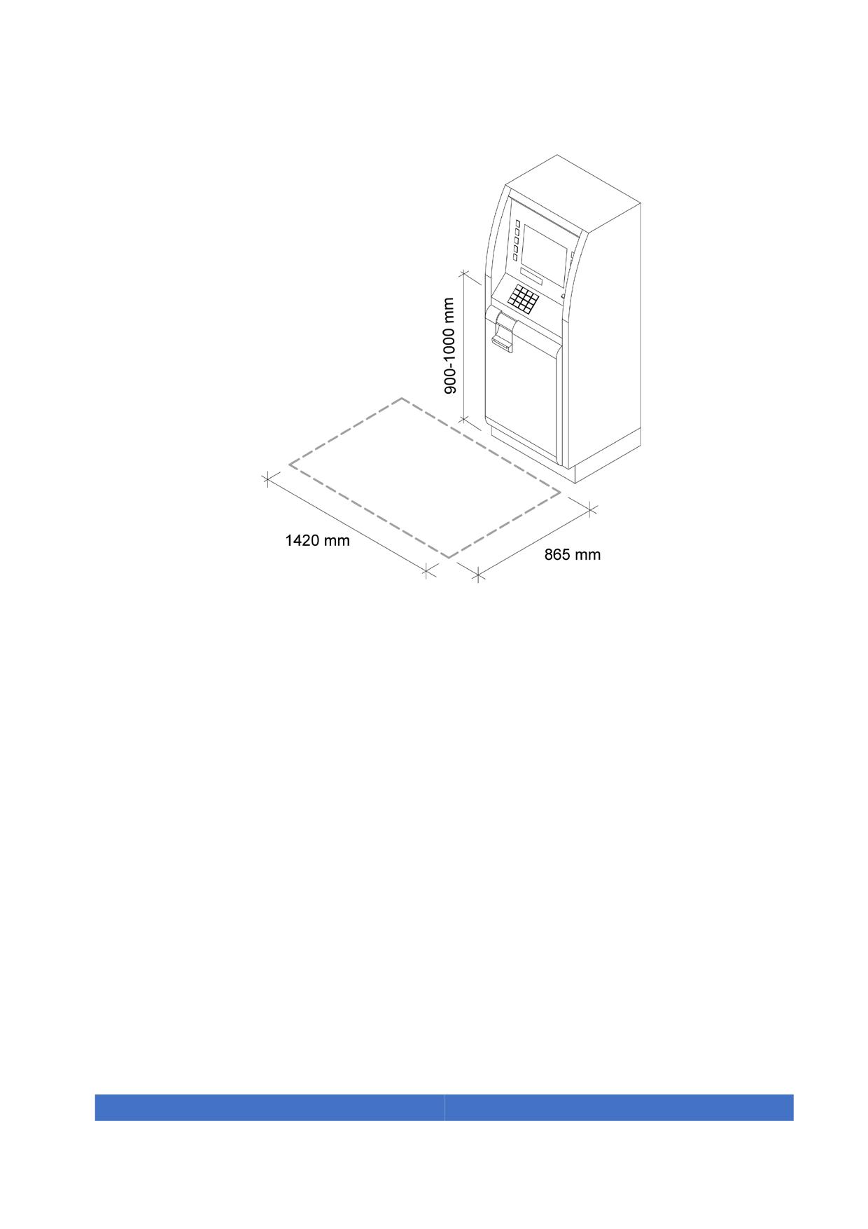
Figure 58. Lateral interaction space in ATM
2. If the vending machine protrudes from the vertical wall, edges must extend to the
floor in all its plane projection.
3. Screen and keyboard are visible from a point located 1000 mm above the floor.
There are no reflections or glare.
4. Direct illumination of the screen has to be avoided.
5. All interaction and control buttons, as well as containers for shipment of products,
must be placed at a height between 400 mm and 1200 mm (preferred between 900
mm to 1000 mm) from the floor and must be separated at least 600 mm from any
corner.
6. Control buttons shall present high embossed text and Braille.
89
7. When bank, identification or validation cards have to be used, the device must meet
the following requirements:
• The card slot is located at a height between 800 mm and 1200 mm from the floor
level and is bevelled to facilitate its introduction.
• It has contrasted colour with the backg0round surface. Tactile symbols and
graphics that represent the card inserting direction must be included.
• It must have a visual and acoustic system to indicate validation of access to the
service and to alert in case of forgetting card or money.
• It shall provide audio for all information.
8. In the case of transport ticket vending machines or ATMs a CCTV Intercom shall be
provided if personnel assistance is not available.
9. The slots are wide and have a funnel effect that facilitates the insertion of coins or
cards.
In all instances, there shall be sufficient dimensions to collect products issued or to
retrieve the card.
5.24.6. Bollards, planters, telephone booths and other furniture
elements
Temporary and permanent installations, bollards, planters, telephone booths or any
facility box shall be located outside the accessible path.
When this is not possible, the object shall present a clear reflectance contrast of at least
30 LRV points with the surrounding pavement. It shall have a geometry following the
requirements of the detection cone in section 5.4.
Bollards, planters, telephone booths and other furniture elements shall not reduce the
accessible travel path to less than 1200mm.
90
6. Public Spaces
6.1. Provisions for public spaces
The provisions of this chapter are applicable to streets in which at least 20% of the
frontage is built and also in parks, beaches and open spaces for public use, including
their facilities, services and urban furniture.
A street, park, open space or a beach is considered for public use when:
• It is part of the public environment and is designed for public use.
• It is part of a privately owned property but is used by public.
• It is part of privately owned property but is subject to a public easement.
• It is likely to be used by the public, either free or for a fee.
Public spaces shall meet the following requirements:
1. All urban furniture and signage shall be aligned without interfering with the
accessible path. All urban elements and furniture related to this path should
follow the design requirements of this Code.
2. In case of cycling paths on the sidewalk they shall be located between the urban
furniture and the curb.
3. A tactile warning pavement as described in section 5.3 shall precede any
pedestrian crossing.
4. In case of a crossing at a lower level the maximum permitted curb cut gradient is
8%.
5. Traffic lights with buttons at accessible pedestrian crossings shall follow the
design criteria described in section 6.10 and provide visual and acoustic
information.
6. Existing public streets and accessible paths in open spaces with running
gradients greater than 5% are allowed due to topographic conditions only, where
there is a technical impossibility to modify the existing gradient. In all instances it
must adopt all other technical requirements that are applicable, according to this
Code.
91
7. When the street is exclusively or mainly designed for pedestrians all areas
between buildings or lots shall be level. In these cases, the path shall present the
described characteristics and all kinds of vehicles shall have their speed limited
to 10 Km/h. A physical speed-calming element shall be installed at all entrances
to the area.
8. Benches or places to sit shall be designed according to section 5.22.2. In the
exterior environment, they shall be placed in the urban furniture zone at least
every 100 m. In large buildings like shopping malls, they shall be placed out of
the accessible path at least every 50 m. Benches with and without arms should
be provided to accommodate people of various sizes.
9. Shaded zones shall be provided at least every 50 m. Fully shaded walking
zones can be achieved by means of a retracted façades or pergolas.
10. Street names shall be displayed at all crossing following the specifications of
section D for information panels. Additionally, it is recommended to provide this
information by audio via an accessible mobile application.
11. Information about the location of the nearest public transport, public toilets and
interest points within the community shall be installed at least every two
crossings following the requirements of section D for information panels.
Additionally, it is recommended to provide this information by audio via an
accessible mobile application.
12. Public toilets should be installed near the accessible walking path, if there are no
toilets for public use within 400 m.
13. Bus shelters, signals, fountains and other urban furniture installed in the vicinity
shall follow the design criteria contained in this Code.
14. When a cycling path cannot be installed in a separate strip between the urban
furniture area and the curb, it is permissible to locate it between the urban
furniture area and the accessible pedestrian path. They should be divided by a
pavement strip of at least 300 mm width with a contrast of at least 30 points LRV
(Light Reflectance Value) or by an easily perceptible texture change.
15. In accessible paths in the vicinity of park entrances, along the public beaches,
near tourist attraction points, in shopping malls and in other places considered
appropriate, electric mobility devices chargers with an interaction space shall be
installed.
92
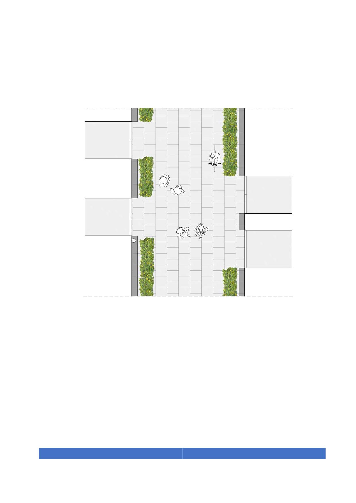
6.2. Street design options
This chapter describes the different types of options for street design that guarantee an
appropriate and comfortable accessible path.
Figure 59. Street at the same level where pedestrians have preference and vehicles
speed, if allowed is limited to 10Km/h
Only streets with sections bigger than 2000mm can be used as a pedestrian path.
93
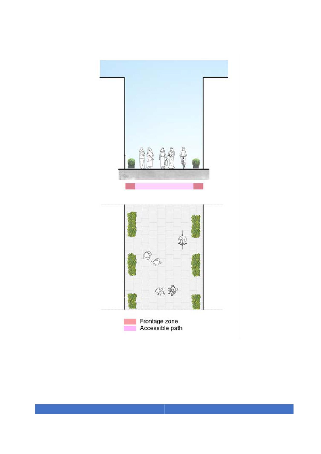
Figure 60. Standard section of a Sikka
Sikkas are excellent opportunities to create pedestrian spaces free of motor vehicles or,
at least where pedestrians have priority.
94
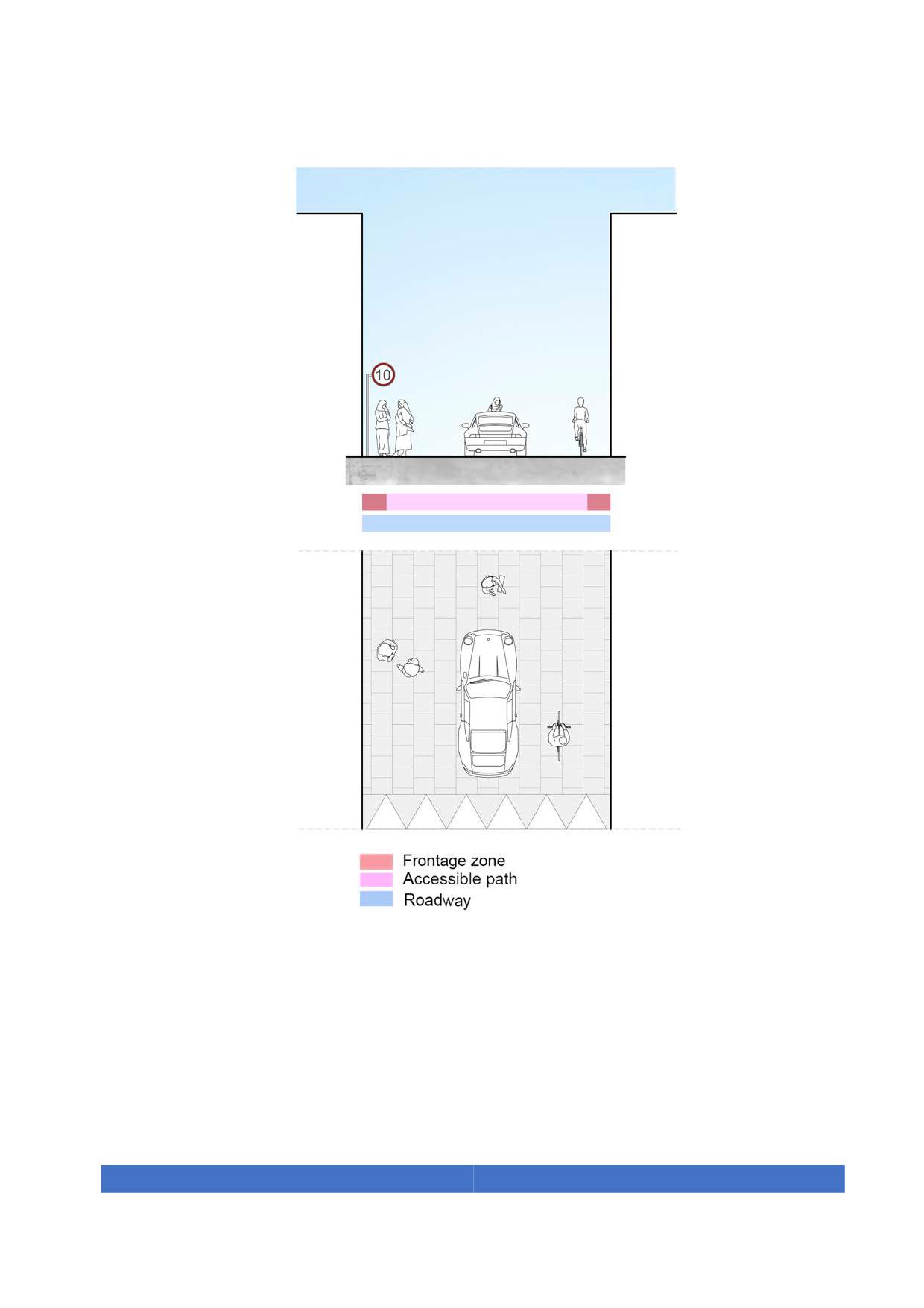
Figure 61. Standard section of a shared street
In the case of shared streets at the same level where motor vehicles are allowed the
street section shall be at least 4000 mm wide and the speed limited to 10 Km/h.
95
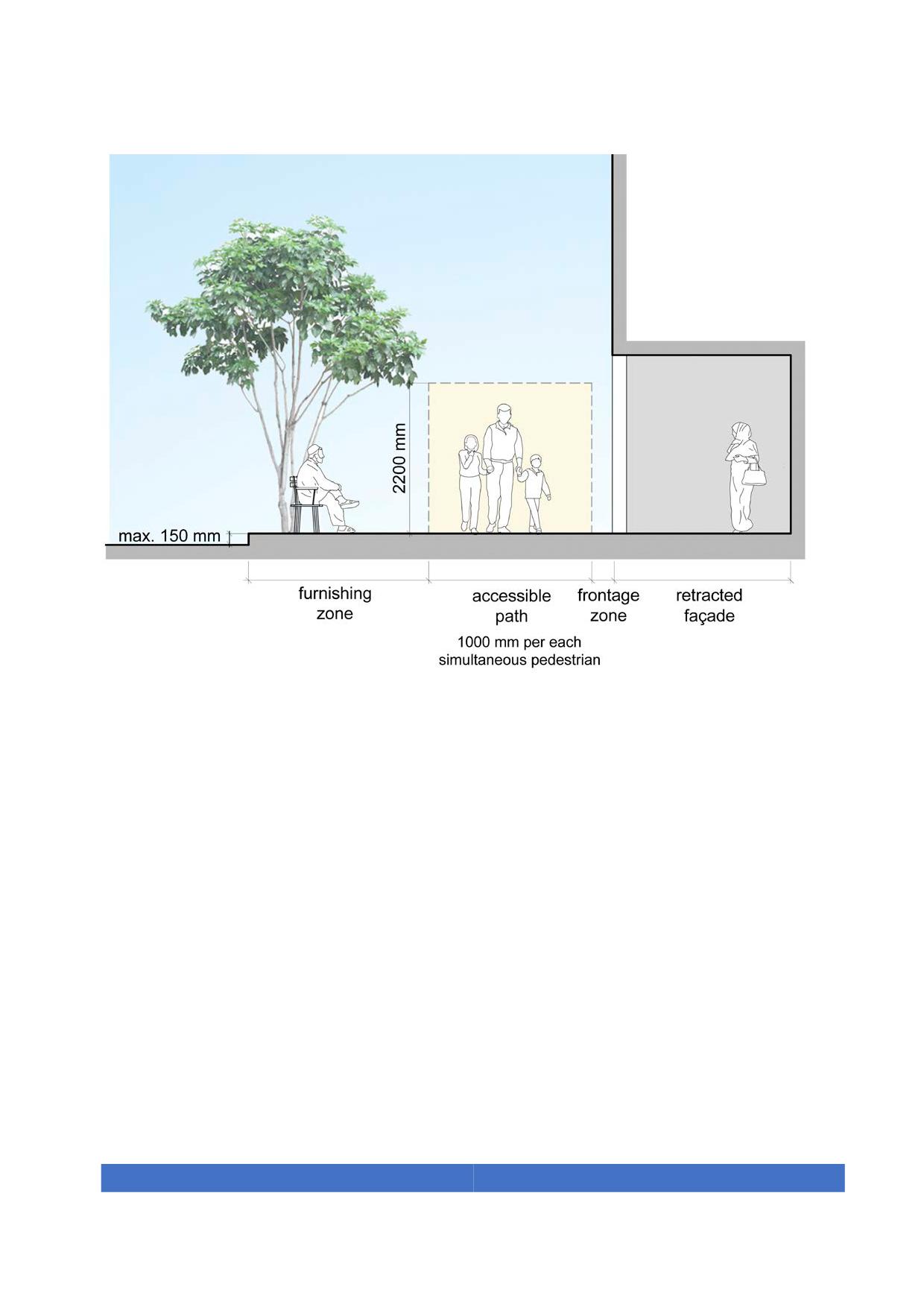
Figure 62. Section of a sidewalk with recessed façade
The design of the sidewalks shall guarantee a travel path with a minimum width of
2000mm although the planners should determine the width according to its
foreseen use.
Retracted façades are also very convenient to provide shade areas to pedestrians.
96
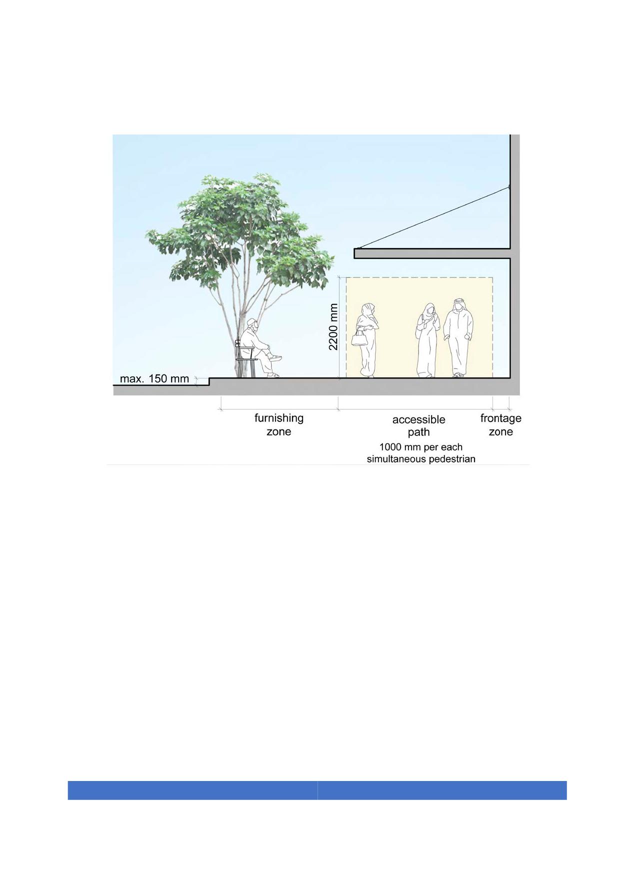
Figure 63. Section of a sidewalk with a pergola
When buildings do not provide retracted façades, pergolas can provide comfortable
shaded areas.
97
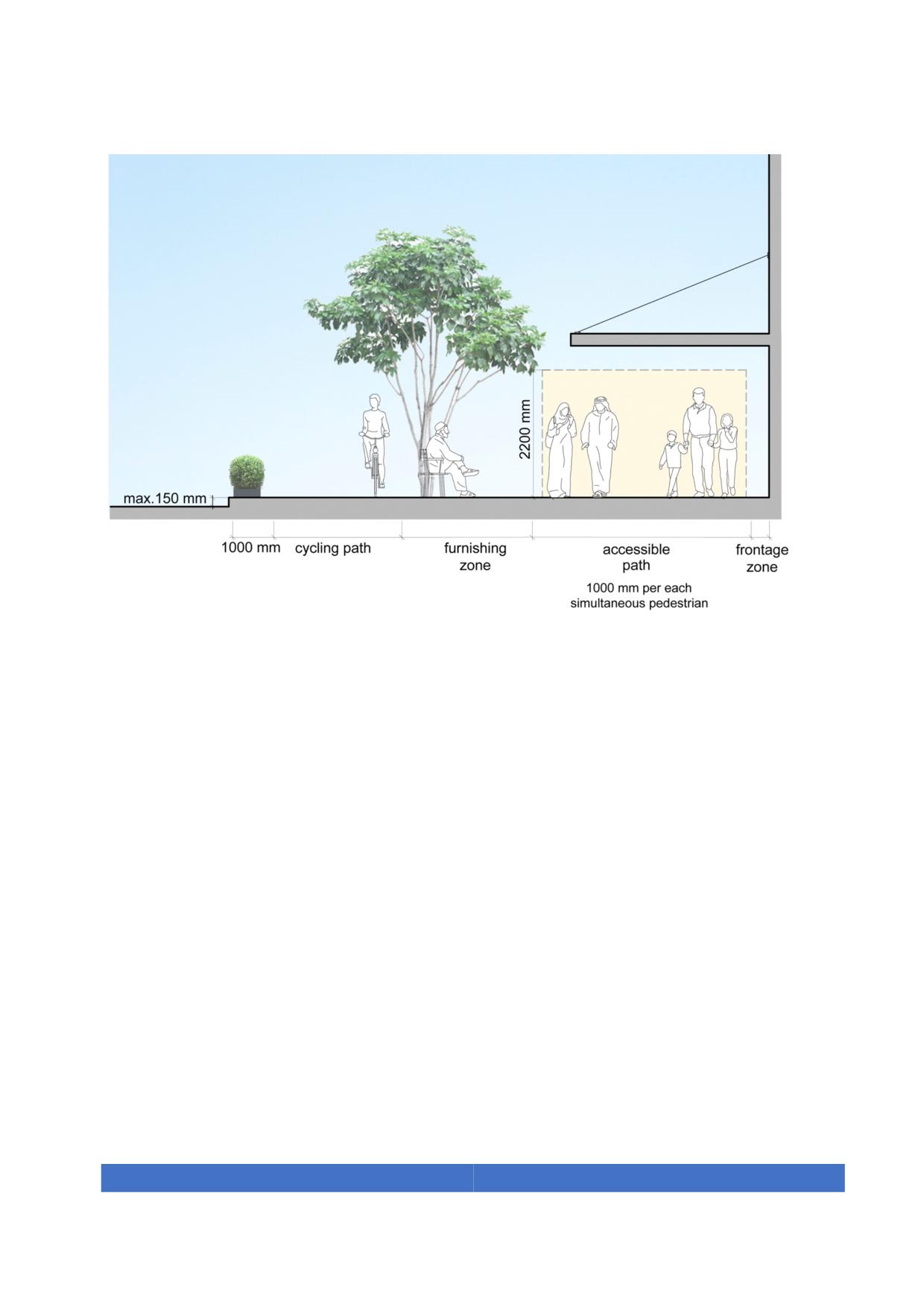
Figure 64. Section of a sidewalk with a cycle path
In new streets cycling lines shall be installed between the urban furniture section and
the curb.
The distance between the cycling line and the parking bay or traffic shall be at least
1000 mm.
The criteria described shall be applied to all street sections that can be found in Dubai
as per the examples below.
98
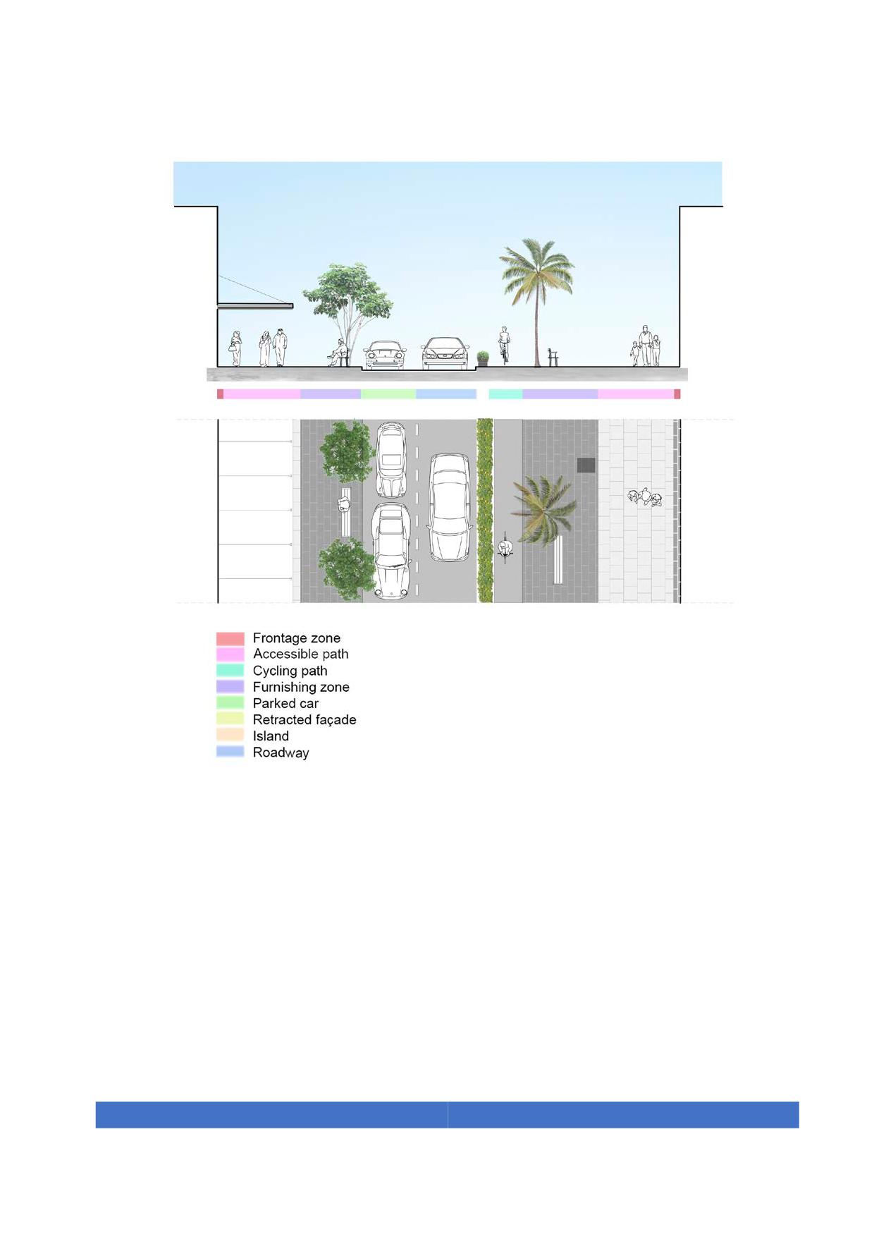
Figure 65. Standard section of a one-way street with a cycling path in one direction
99
//////////////////////////////////////////