Dubai Universal Design Code (2017) - page 2
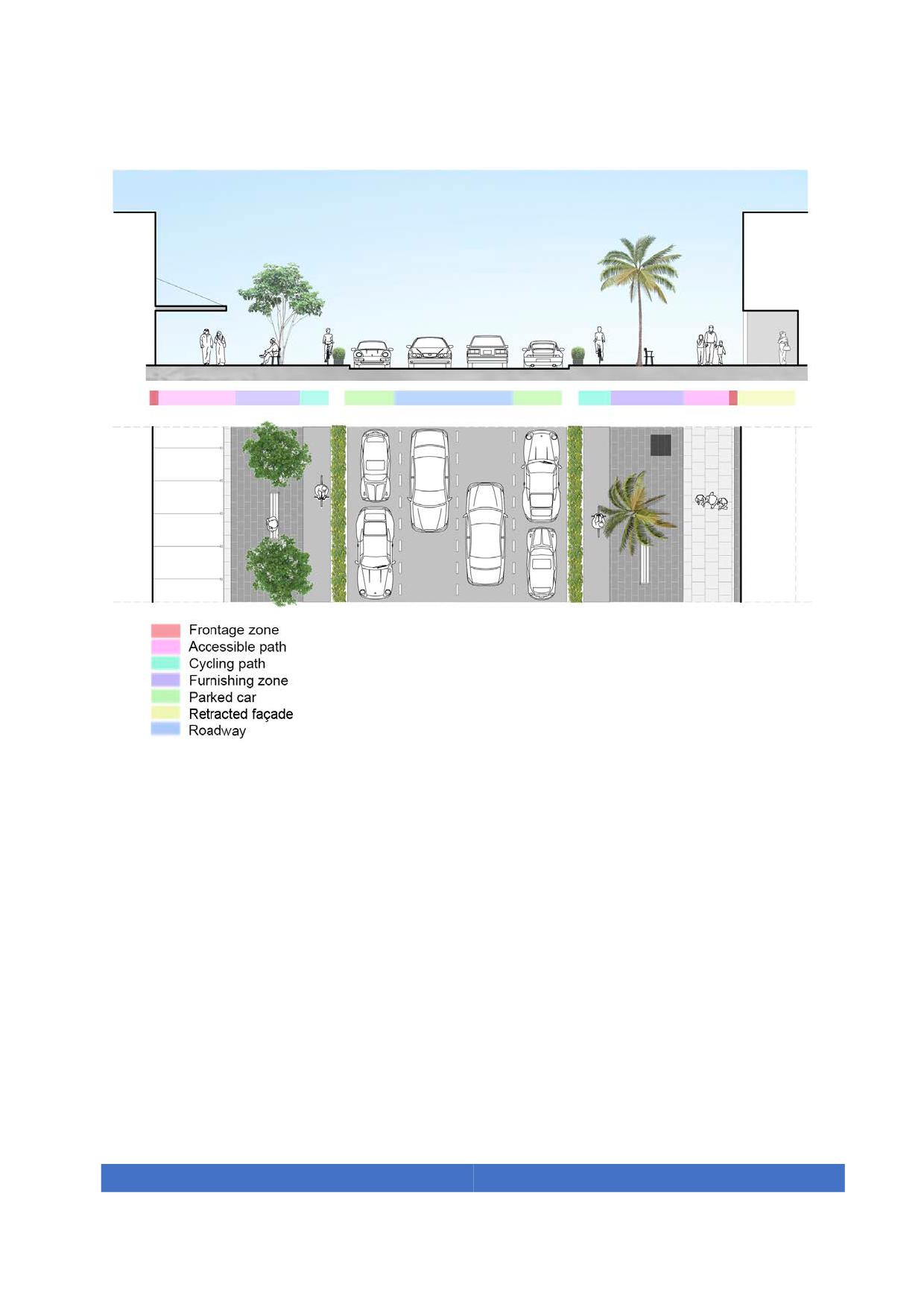
Figure 66. Standard section of a two-way street with cycling paths in both directions
100
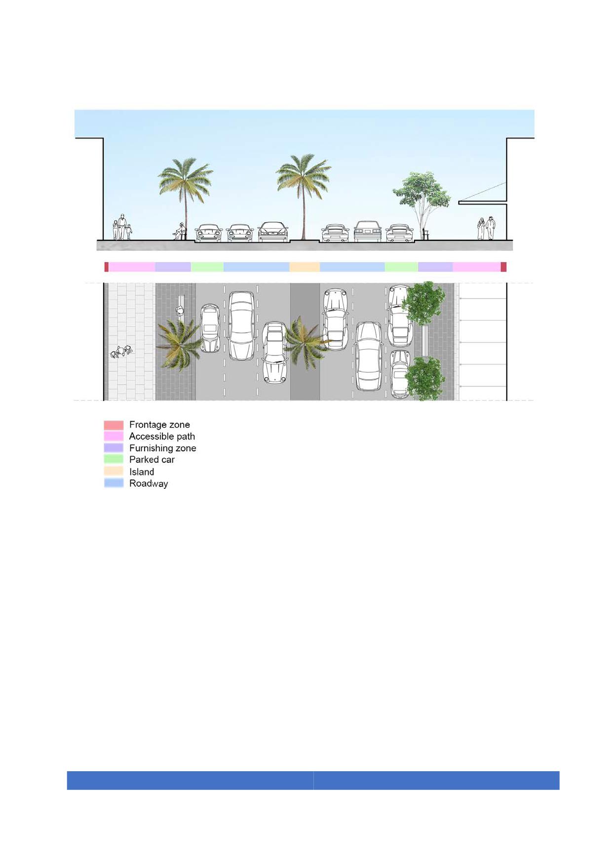
Figure 67. Standard section of a two-way street with an intermediate island
101
6.3. Curb Ramps
Curb ramps are elements of an accessible pedestrian path that connect different levels
through inclined planes, usually between the roadway and the sidewalk.
Curb ramps, regardless of type must meet the following criteria:
1.
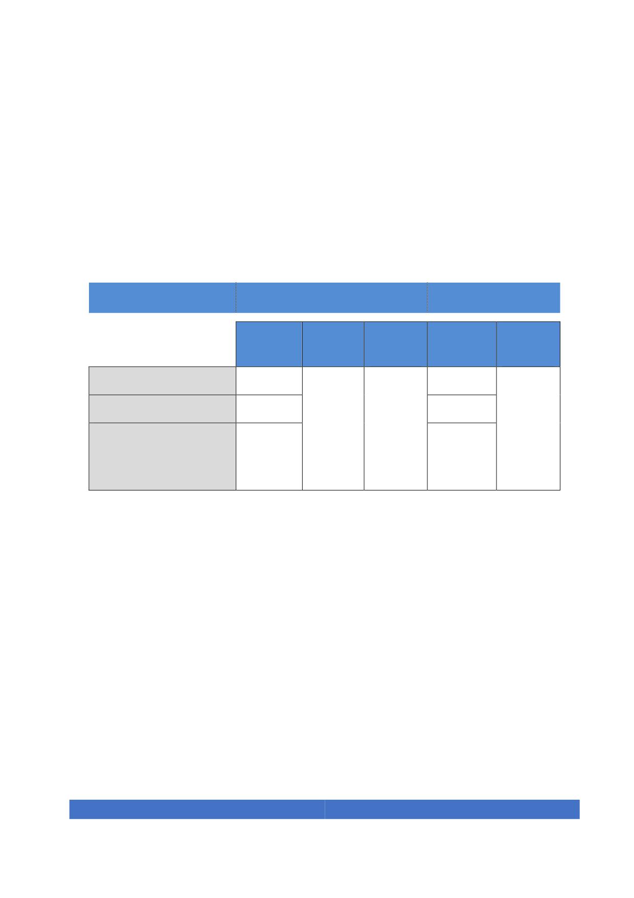
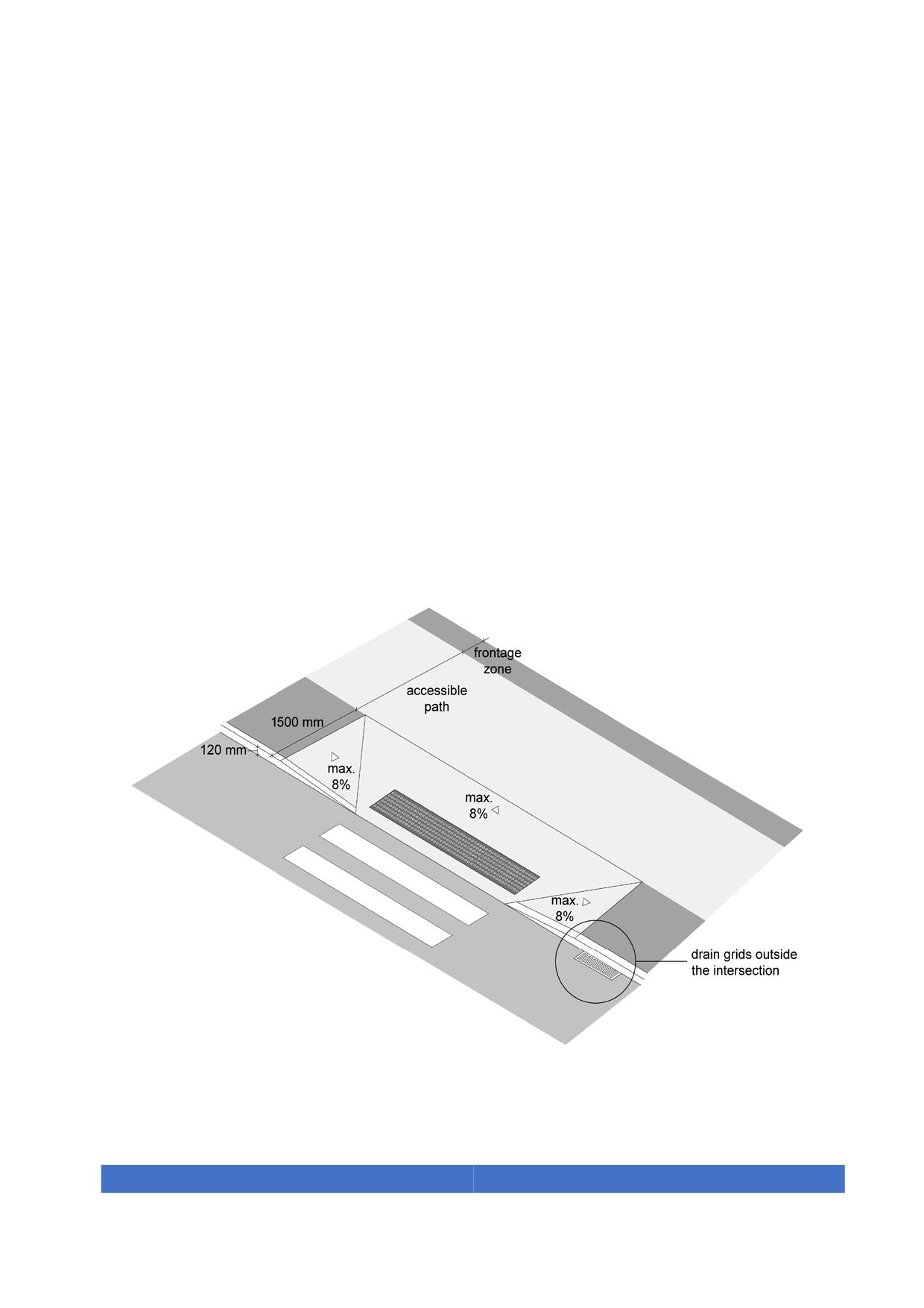
The running gradient maximum is 8%. Depending on the height of the sidewalk the
length will vary following table 9. The curb height shall be between 100 mm and 150
mm.
Sidewalk height
Central passage dimensions
Flared sides
Max.
Max.
Length
Width
Length
gradient
gradient
100 mm
1250 mm
1250 mm
Equal to
150 mm
1875 mm
1875 mm
crossing
8%
8%
200 mm
painting
(only for existing
2500 mm
>2,00m
2500 mm
sidewalks)
Table 9. Dimensions and gradients of curb ramps
2.
The total width of curb ramps in pedestrian crossings is the same as the accessible
pedestrian path and never less than 2000 mm with no interruptions by any obstacle
or any raised pavement. In accessible parking places or drop-off zones, curb ramps
should have a minimum width of 1200 mm or the width of the lateral aisle.
3.
Except for curb ramps in parking places, curb ramps shall have a warning tactile
pavement at 300 mm from the edge.
4.
Curb ramp edge surfaces have to be completely level with the road.
5.
The colour and texture of the curb ramp shall be identical to the accessible
pedestrian path.
6.
Slip resistance value shall be higher than 45 PTV, as indicated in section 5.2.
7.
The maximum cross slope gradient maximum is 2%.
102
8. Curb ramps must not interfere with the accessible path.
9. When the curb ramp design causes a step in its lateral edges, this level change
should be protected by some element or urban furniture.
10. Curb ramps located on both sides of a street must be aligned.
11. Drain grids shall never be within the accessible pedestrian crossings.
6.3.1.
Types of curb ramps
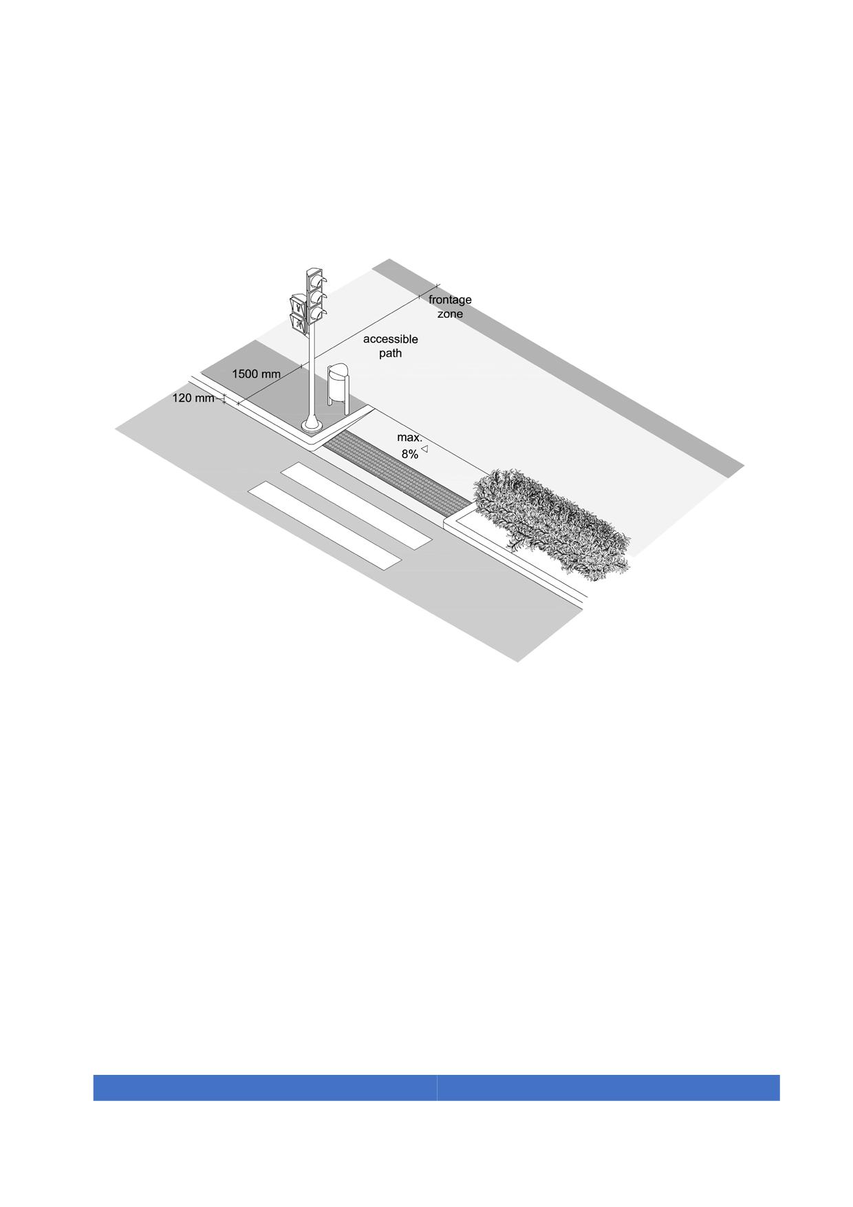
1. Curb ramps with flared sides
Curb ramps with flared sides are comprised of three slopes.
All gradients shall be a maximum of 8%. This type of curb ramp is preferred.
Exceptionally, flared sides of ramps located in parking and drop off areas can have
higher cross gradient slopes, but never more than 12%.
Figure 68. Example of flared side curb cuts
103
2. Returned curb ramps types
Returned curb ramps are comprised of a single slope placed longitudinally from the
crossing direction, creating two different levels of variable heights on its sides.
Figure 69. Example of returned curb cut
3. Curb ramps in curb extensions
This type is appropriate when the sidewalk is narrow. Extensions in the street corners
can be created to reduce the pedestrian crossing distance.
104
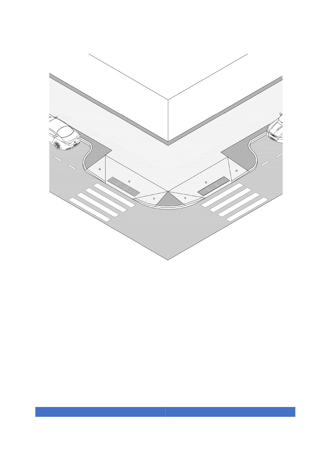
Figure 70. Example of curbs ramp extensions
4. Lowered sidewalk curb ramps
When the sidewalk width is too narrow to use the other curb cut types, lowered sidewalk
curb ramps should be implemented.
This curb ramp is comprised of two running slopes that lower the sidewalk’s full width to
the roadway level. A landing of minimum 2000 mm long should be provided between
the two slopes. The border level with the roadway shall include a tactile warning
pavement.
This is the only curb ramp that can obstruct the pedestrian path.
105
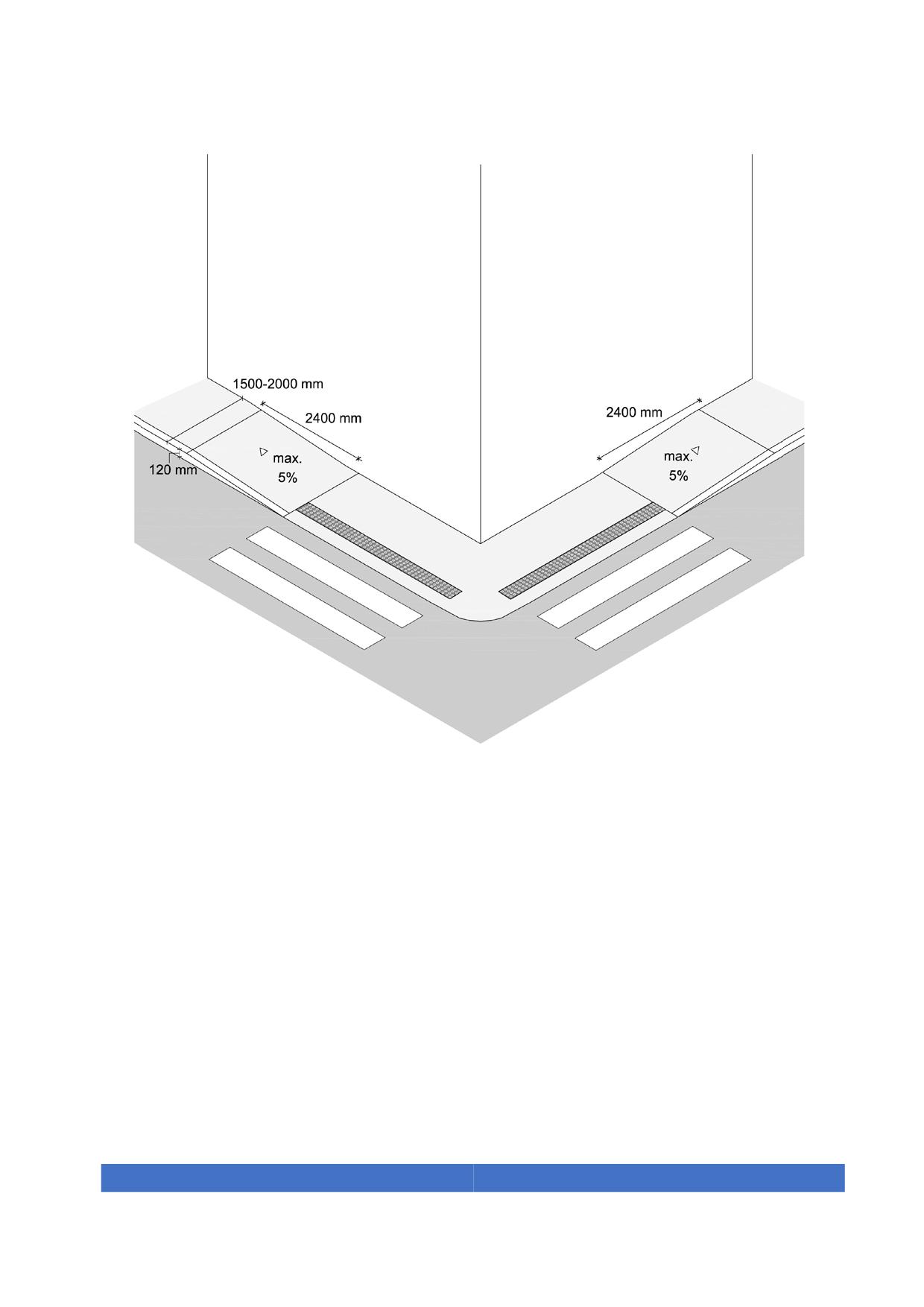
Figure 71. Example of depressed curb cut in a corner
6.4. Prohibition of accessible path alterations
The level difference between the sidewalk and the vehicle’s access to parking should be
solved preferably inside the building or lot.
Provisional or added ramps and steps shall not affect the shape or invade the
accessible pedestrian path.
Parking or garage doors shall not obstruct an accessible pedestrian path.
106
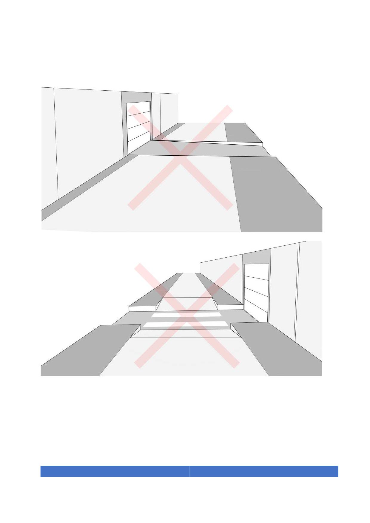
Figure 72. Incorrect solutions to provide access to garages
107
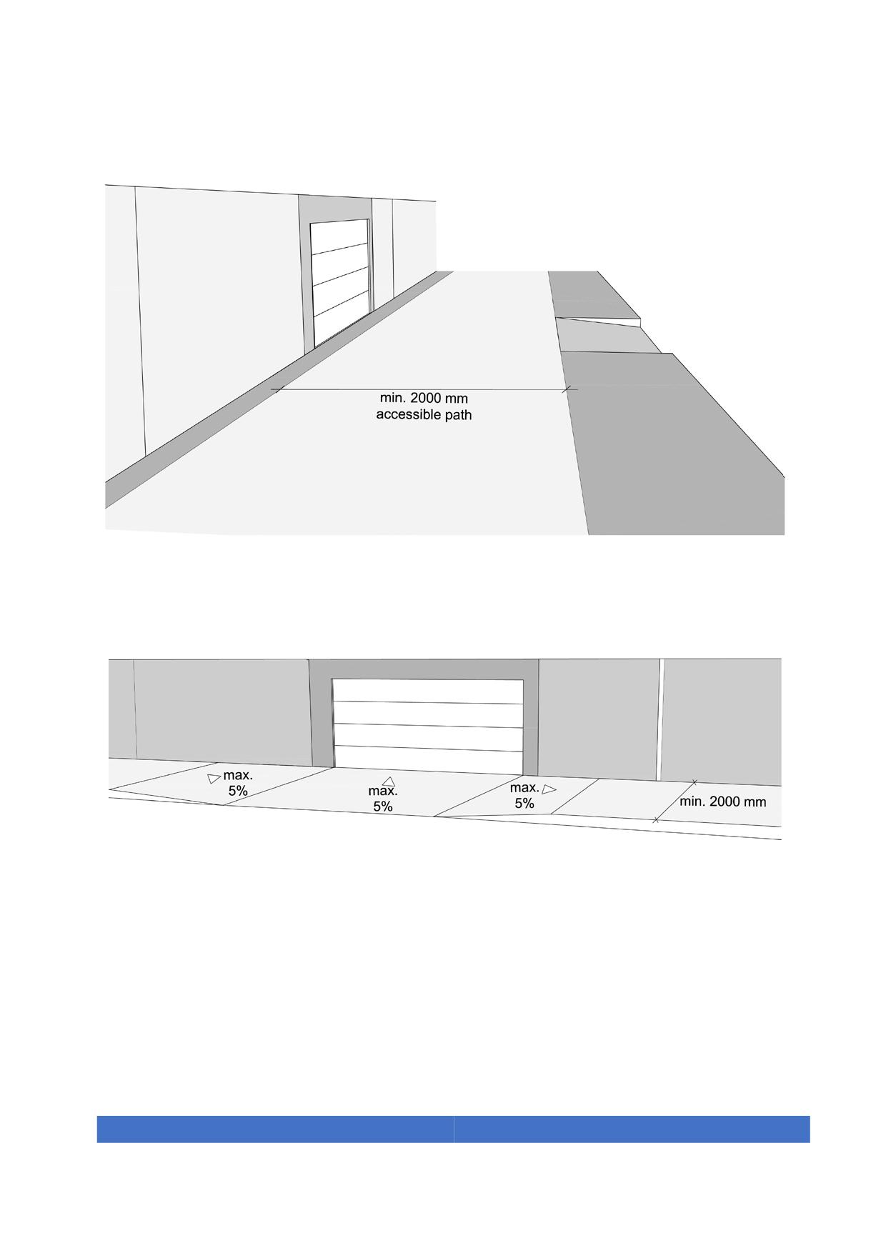
Figure 73. Possible solution to provide access to garages
Figure 74. Slight depression of sidewalk is only allowed when this is the only alternative
108
6.5. Intersections
All intersections between pedestrian paths and roadways must be accessible in order to
allow passage to all users, regardless of their functional limitations.
The pavement colour and texture of the surface that connects the accessible path to the
crossing shall be identical to the pedestrian path.
If there are traffic lights at the pedestrian crossings, they should meet the specifications
of section 6.10.
6.6. Intersections with raised pedestrian crossing
The sidewalk shall maintain a continuous surface without lowering to the roadway level
during the crossing. Pedestrians should not experience any changes in ground level
during the crossing of the intersection.
This intersection is considered accessible when it fulfils the following requirements:
1. The total width of the continuous raised surface above the roadway is:
• At least 7000 mm when there are bus lanes or coaches or their passage is
expected in the roadway.
• The same crosswalk width or at least 2000 mm from the roadway ramp, without
being interrupted by any obstacle or any pavement rising.
2. The surface height shall be between 100 mm and 150 mm above the road, and the
longitudinal gradient of the roadway ramp cannot exceed more than 15%.
3. The crosswalk is marked on the raised surface for all its width.
4. The sidewalk edge of the pedestrian crossing should be marked with a strip of tactile
warning surface. This tactile warning surface has to run the width of the pedestrian
path and has to fulfil the requirements established in section 5.2.
5. Roadway water evacuation solutions should be resolved without causing a level
change, a step or a gap across the crosswalk.
109
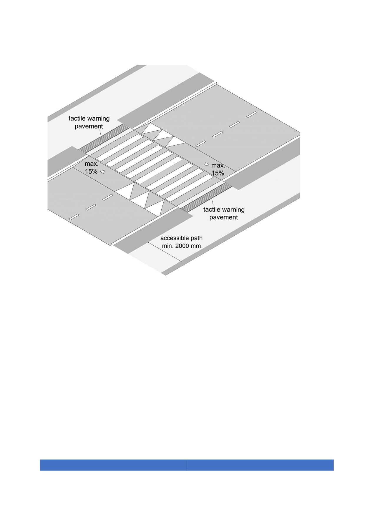
Figure 75. Example of a raised pedestrian crossing
6.7. Level roadway
The roadway shall maintain a continuous surface without a rise in level to the sidewalk.
Pedestrians must go through two level changes during the crossing.
This intersection is considered accessible when it fulfils the following requirements:
1. There is a curb ramp at each end of the pedestrian crossing to connect the sidewalk
and the roadway. The curb ramps on each end shall be aligned. These curb ramps
have to fulfil the requirements of section 6.3.
2. The sidewalk edge of the pedestrian crossing should be marked with a strip of tactile
warning pavement. This tactile pavement should run all the width of the pedestrian
path and should fulfil the requirements of section 5.2.
110
3. If the intersection crosses a tramline, it shall not cause any unevenness or
irregularity in the crosswalk, except for the longitudinal opening of the railway rails,
which should be the minimum that is allowed by the transport system. At the
crossing there must be a clear reflectance contrast of at least 50 LRV points
between the railway tracks and the rest of the pavement, and 300 mm wide
detectable warning pavement in both ends.
6.8. Intermediate islands
A pedestrian speed of 0,6 m/s should be used to assess the crossing speed of
pedestrians. If the time to cross the crosswalk is not enough due to the street’s length,
an intermediate island should be provided.
The intermediate islands should fulfil the following requirements:
1. The length of the island shall be at least 1500 mm.
2. The island pavement should be the same colour as the pedestrian path. Both island
edges should be marked with detectable warning pavement at least 300 mm wide
and the same width as the pedestrian crossing.
When two traffic directions are separated by an intermediate island and have different
green cycles, pedestrians should be required to wait in the central island for the green
light and guardrails shall be placed to guarantee that pedestrians stop in the island.
The offset intermediate islands should fulfil the following requirements:
1. The entrance and exit of the pedestrian crossing at the intermediate island shall be
misaligned.
2. The path between the entrance and the exit shall be protected on both sides with
guardrails, dwarf walls or other protection elements.
3. The island pavement should be the same colour as the pedestrian path. Both
island’s edges should be marked with detectable warning pavement of at least 300
mm wide and the same width as the pedestrian path.
111
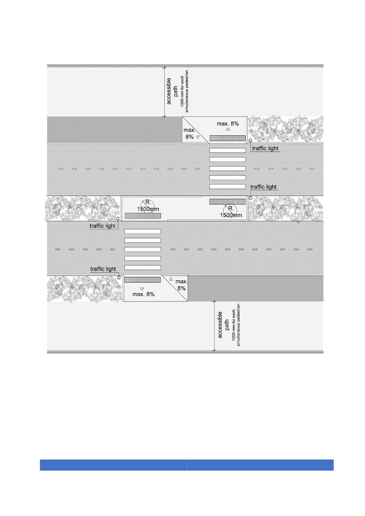
Figure 76. Offset intermediate island
112
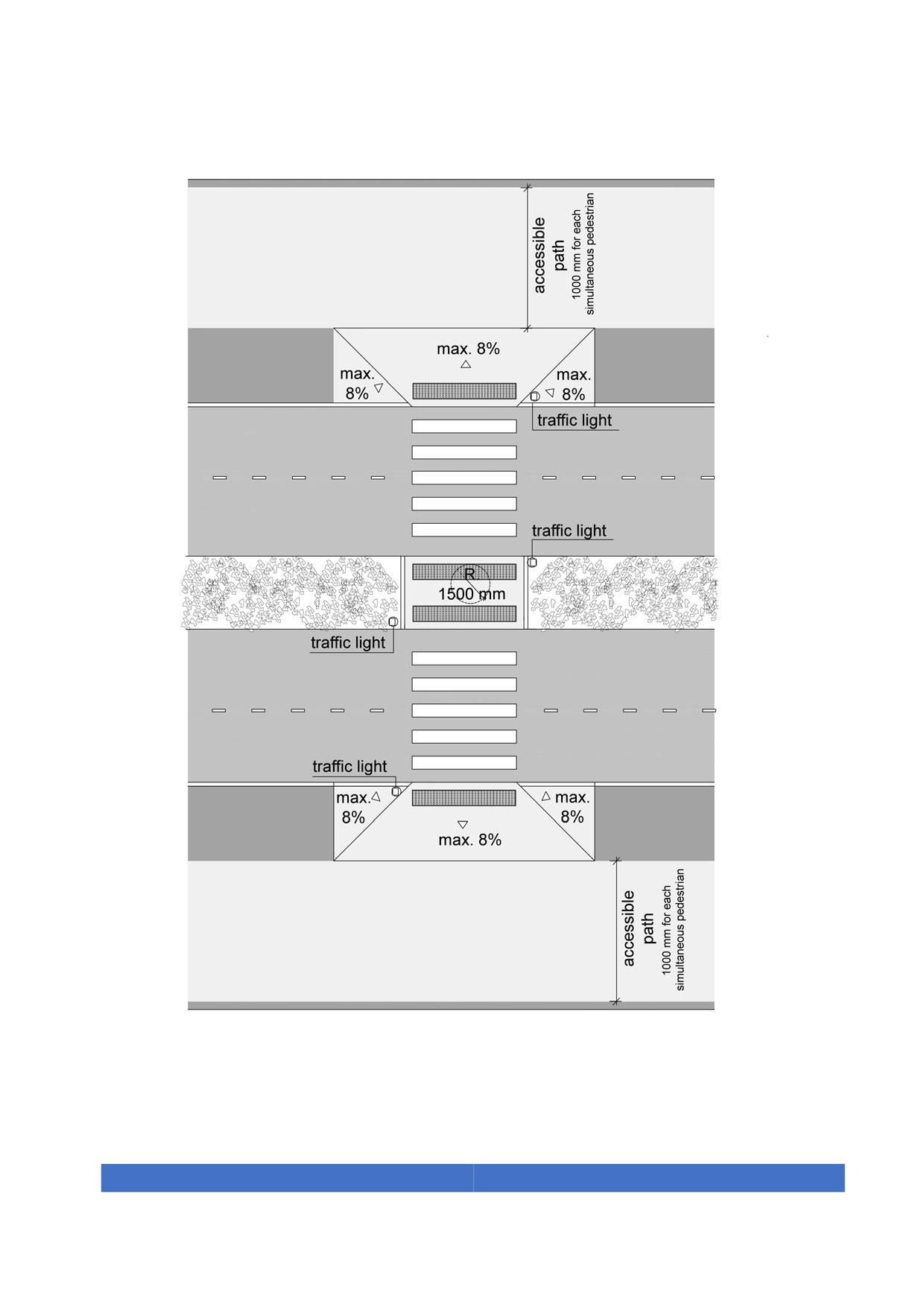
Figure 77. Aligned intermediate island
113
6.9. Intersections in shared streets
Neither pedestrians nor vehicles experience any changes in ground level during the
passage of the crossing.
It is considered an accessible intersection when:
1. Pedestrians can cross the street at any designated crossing point.
2. If a tramline crosses a shared street, it shall not create any unevenness or
irregularity in the crossing, except for the longitudinal opening of railway rails, which
should be the minimum that is allowed by the transport system. At the crossing,
there shall be a clear reflectance contrast of at least 50 LRV points between the
railway tracks and the rest of the pavement 300 mm wide detectable warnings shall
be located at the beginning and at the end.
6.10. Accessible pedestrian signals
In addition to the visual traffic signals, accessible pedestrian signals on the accessible
pedestrian crossing shall have three types of sound signals that fulfil the following
requirements:
1. Activation acoustic signals: it is activated by user demand by touching the area
around the traffic light button or by a mobile application that links the user’s phone
with the traffic light. It identifies the exact location of the transmitter signal and the
location of the pedestrian crossing. This signal informs the user of the activation of
the pedestrian crossing signal in the next passage cycle. It should be of short
duration, with eight tones in two rounds.
2. Pedestrian crossing signals: automatically emitted during the pedestrian crossing
cycle and maintained throughout the cycle. It has a distinctive tone, slow and
intermittent.
3. Pedestrian signals for final crossing: it matches the final flashing green light cycle
and informs of the imminent finishing crossing time. It has a distinctive tone, fast and
intermittent.
4. The sound shall be set to ensure the crossing time of the traffic light cycle, taking
into account a maximum pedestrians’ speed of 0,6 m/s. If this requirement cannot be
fulfilled, it is mandatory to provide intermediate islands. These islands shall have
traffic lights with their own systems of visual and acoustic signals.
114
Pedestrian Crossing Signals on public streets shall meet the following criteria:
1. Users with visual disabilities must be able to activate the acoustic signal of the traffic
light using a smart phone application.
2. The pedestrian signal pushbutton shall be mounted at a height between 900 mm
and 1200 mm and should be accessible with tactile characters. It must meet the
criteria of strength and ergonomic shape to be operated with the elbow.
6.11. Shaded areas
The provision of continuous shaded paths is encouraged and at minimum-shaded areas
shall be provided every 50 m in streets and squares. Each second area shall be
provided with seating places and adequate space for wheelchair users without invading
the accessible path. Shaded areas shall be provided by trees, pergolas and retracted
façades.
6.12. Pick-up and drop-off areas
Pick-up and drop-off areas for taxis and private cars shall include curb ramps similar to
those at accessible parking places.
Drop-off areas shall be provided in front of administration buildings, health care
services, shopping malls, hotels, parks, transport buildings, theatres and cinemas and
amusement parks.
6.13. Accessible parking bays and access to parking lots
Public or private parking areas associated with a public street, open space or building
shall have accessible parking places for holders of accessible parking stickers issued by
any jurisdiction.
The number of accessible parking places shall follow table 10.
115
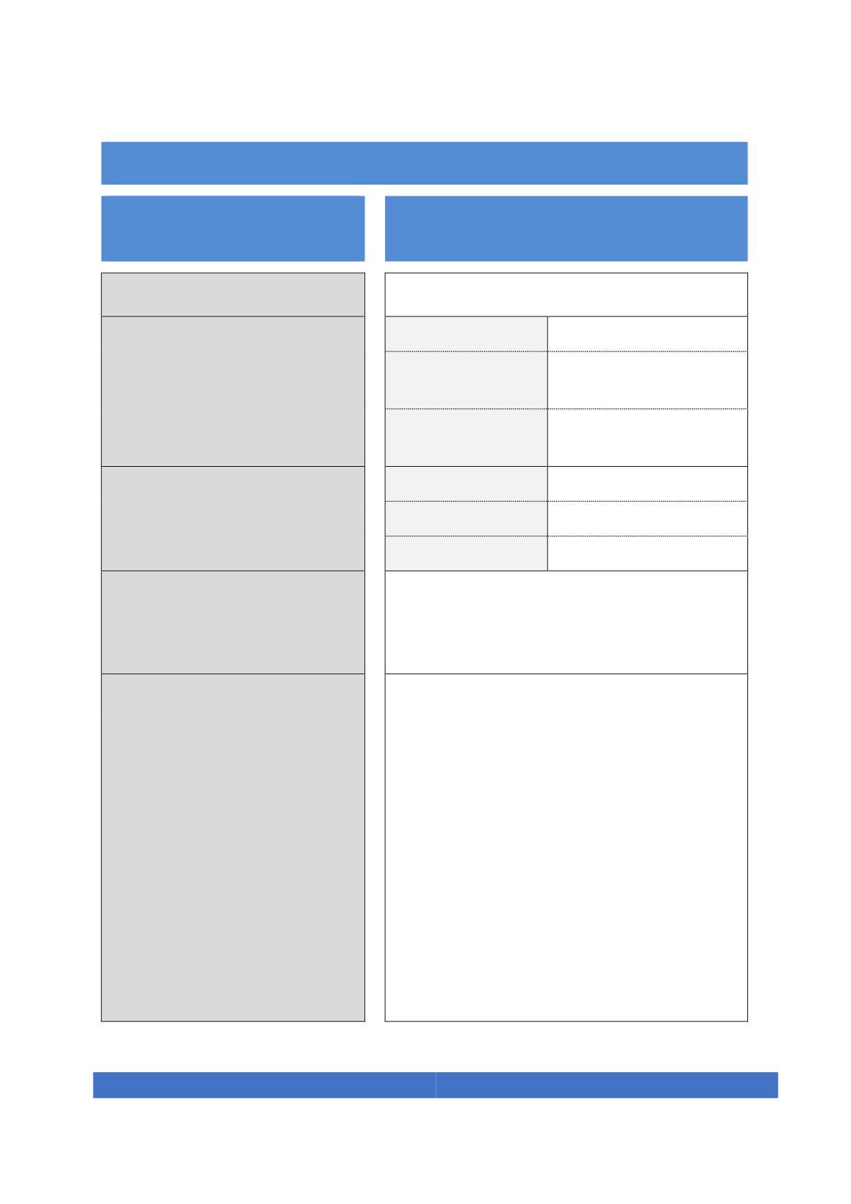
ACCESSIBLE PARKING PLACES
Use of the Building,
Minimum Number of Accessible Places
establishment or area
Residential
1 every 33 places
≤ 200 spots
1 every 33 places
Public Parking
1 more every 100
201 to 1000 spots
places
1 more every 200
> 1000 spots
places
10 to 200 spots
1 every 50 places
Others
201 to 1000 spots
1 more every 100 places
> 1000 spots
1 more every 200 places
Buildings with reserved seating
space for wheelchair users
1 every 2 reserved seating spaces for
such us cinemas, sport
wheelchair user
facilities and others.
Buildings and open spaces
without parking facilities but
with the following uses:
- Administration headquarters
- Hospitals
2 bays in the public areas. These
- Education buildings
placesshould be as close as possible to the
entrance of the building.
- Sport facilities
- Beaches with accessible
paths
- Rehabilitation and day care
centres
- Clinics
Table 10. Number of accessible parking places
116
Accessible parking places shall meet the following technical requirements:
1. Accessible parking places should be located as near as possible to facilities such as:
hospitals, clinics, schools, museums, cinemas, theatres, cultural centres and
shopping malls and near access to beaches, parks, gardens and squares.
2. They shall be located as close as possible and no more than 50 meters from the
building entrance. They should be located next to an accessible pedestrian path, to
ensure access to the sidewalk from the road or they should provide an accessible
curb ramp exclusively for each accessible parking place. A single curb ramp may be
shared by two parking places.
3. The minimum dimensions for the accessible parking place shall be 2600 mm x 5500
mm for angled parking schemes and 2600 mm x 6000 mm for parking places along
the sidewalk. For cases where accessible vans park frequently, the dimensions
should be adapted to the vehicle size.
4. Accessible parking places shall have a lateral access aisle to allow for approach and
transfer from the driver’s side for angled parking schemes, and a rear access aisle if
parking places are along a sidewalk. These access aisles shall be at least 1200 mm
wide. They shall connect to an accessible path.
5. They shall be properly marked with the international symbol of access, painted on
the ground and on a signpost. This sign should be easily visible from the driving
position and mounted at a height of 2200 mm.
117
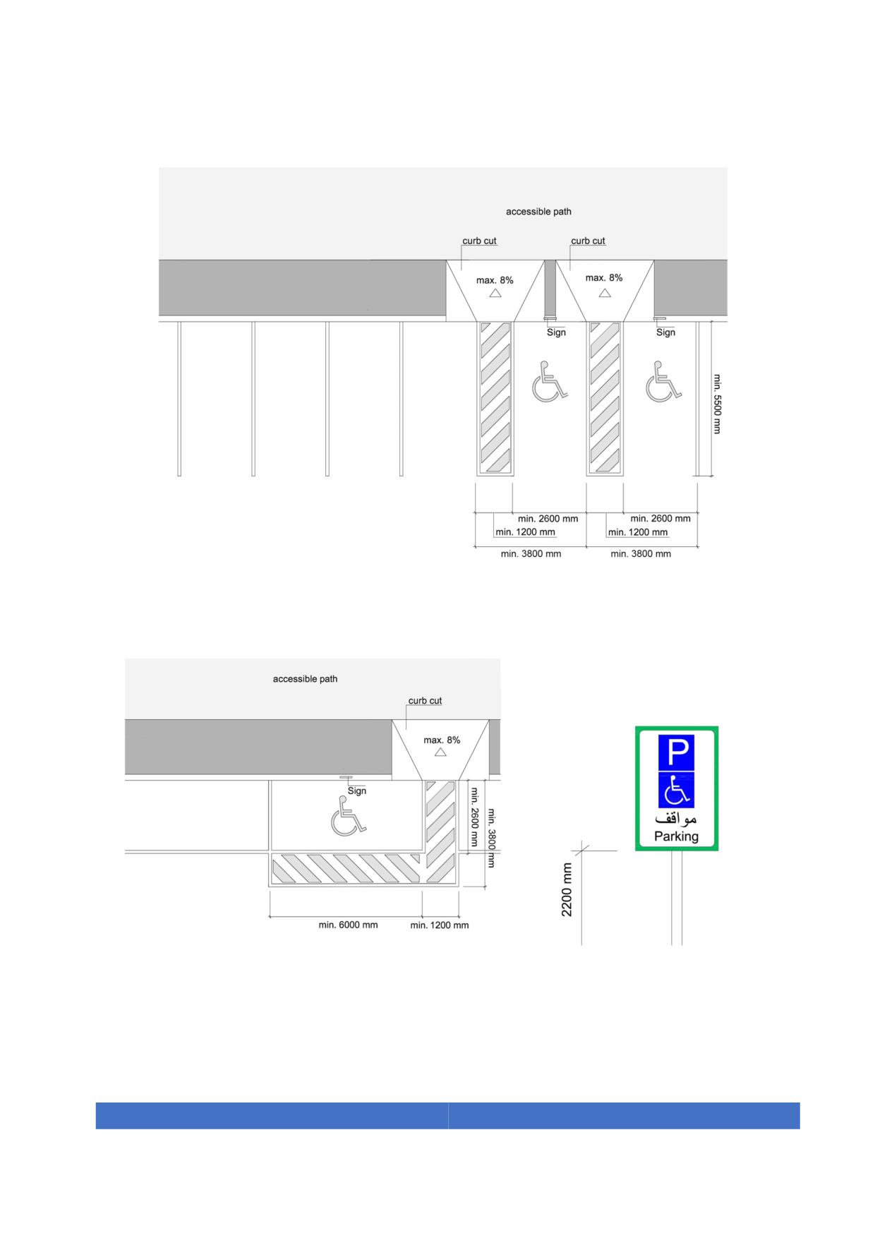
Figure 78. Example of accessible parking places with lateral aisle
Figure 79. Example of an accessible parking place along the sidewalk with sign on post
118
6.14. Bicycle parking
Cycle parking located in public urban environments shall fulfil the following
requirements:
1. They shall be located both close to entrances of public transport stations and to
building entrances and near the pedestrian paths.
2. They should be installed at ground level without obstacles like stairs or steep slopes.
3. They shall be installed in the furnishing zone between the accessible path and the
cycling path. They shall always be located out of the accessible path.
6.15. Mailboxes, parking meters, garbage and recycling containers
To ensure compliance with accessibility provisions the criteria listed below shall be
fulfilled:
1. These shall provide a frontal or lateral interaction space that shall fulfil the
requirements of section 5.5.
2. All interaction mechanisms must be accessible and be located at a height between
700 mm and 1200 mm.
3. At least one of the accessible garbage containers shall be operable by use of one
hand and with a force less than 25 N.
119
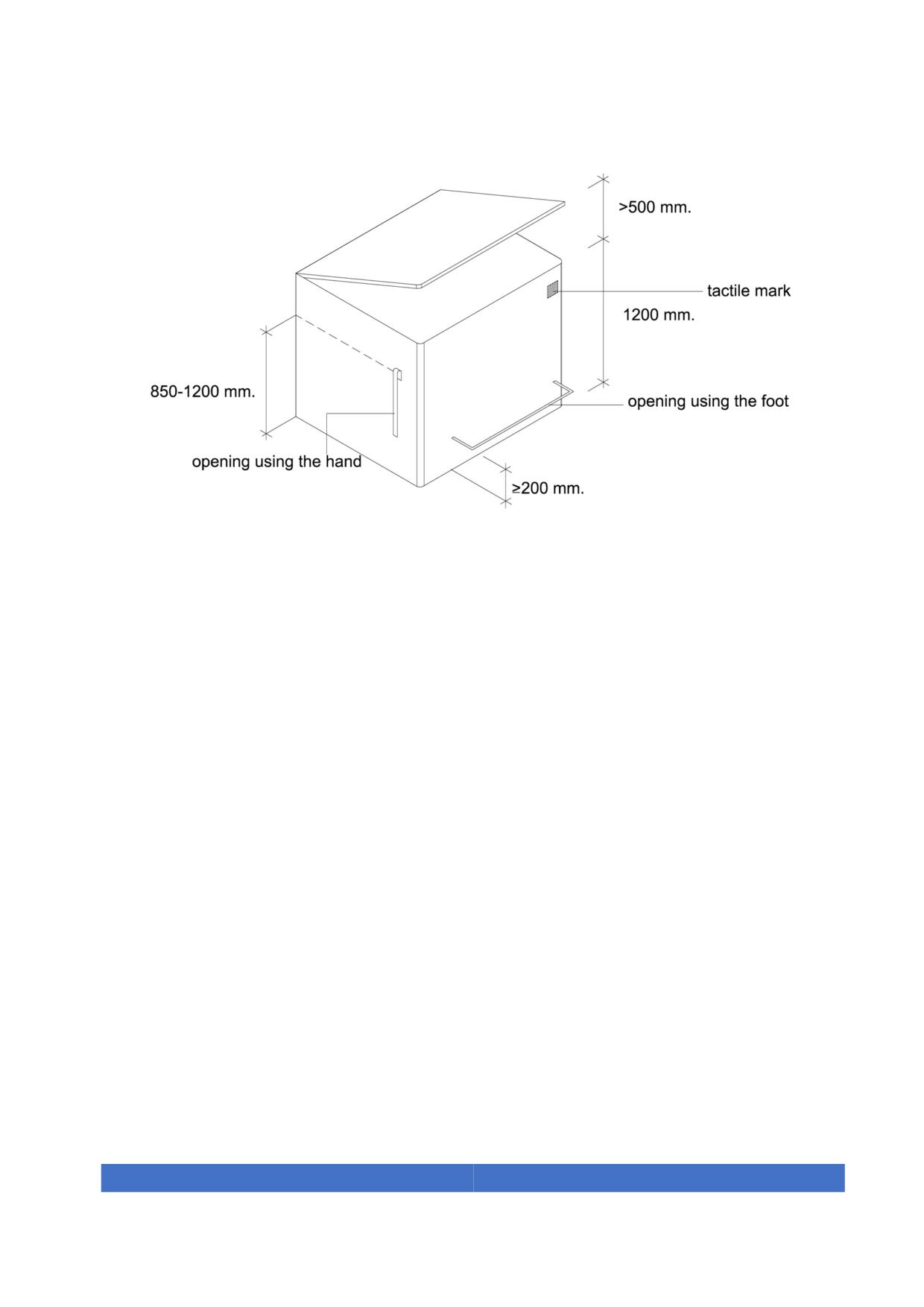
Figure 80. Example of an accessible garbage container
6.16. Restaurant terraces
Temporary facilities and signs located on sidewalks, squares and outdoor spaces such
as terraces or signs for cafes and restaurants shall meet the following criteria:
1. They should not invade the accessible path and they shall not invade the headroom
clearance.
2. They shall not interrupt the guidance element (façades, walls, guardrails...) without
providing an alternative.
3. In case of interruption of the accessible path, the perimeter of the terrace shall be
protected by a continuous element, except in the access areas, with a minimum
height of 900 mm. This element must be easily detectable by people with visual
disabilities.
4. The clear width required for accessible paths may be increased depending on the
expected flow of pedestrians in the area but shall never be less than 2000 mm.
5. In the case where terraces are installed near the vehicles traffic bollards or other
rigid obstacles they shall be installed every 1200 mm.
120
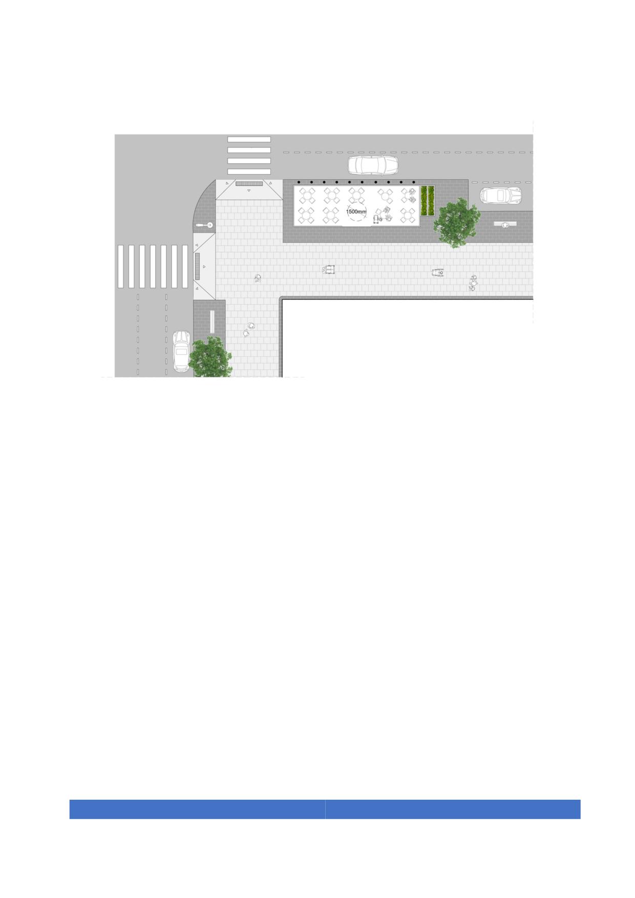
Figure 81. Terraces should be placed in the furniture zone of the sidewalk. Parking
places can be integrated into the terrace
121
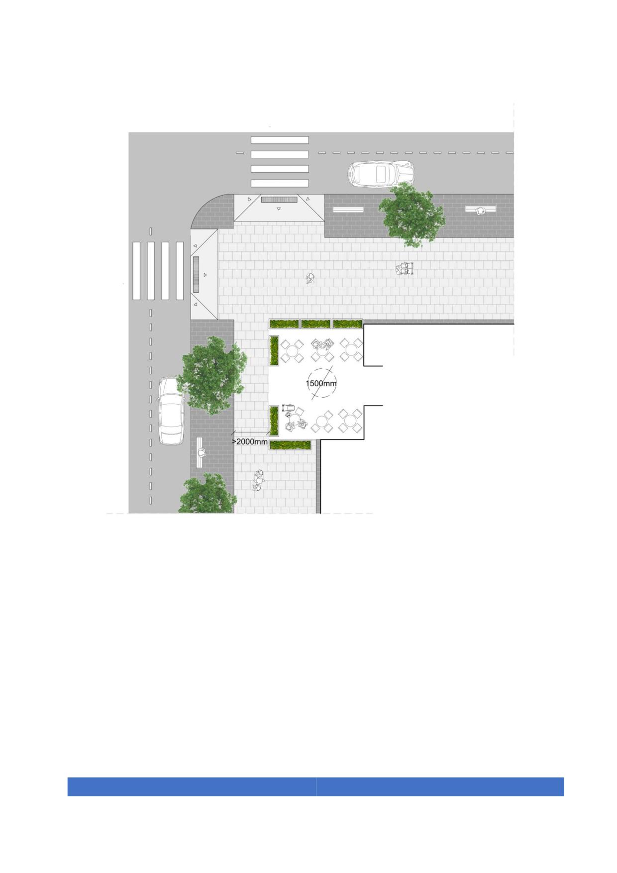
Figure 82. Terrace exceptionally invading the walking path but protected by a fence and
leaving at least 2000 mm of clear walkway
122
6.17. Scaffolding, trenches and other construction works
No public or private work can lessen, permanently or temporally, the conditions of
accessibility established in this Code.
Trenches and construction work in public spaces shall fulfil the following conditions:
1. They shall be protected with stable and solid fencing and protection elements
that prevent people falling into the trenches or construction site.
2. People with visual disabilities shall be able to detect them easily; therefore, all
protective and warning elements shall have a detectable edge at a maximum
height of 680 mm.
3. Warning lights and audible signals shall be provided to alert people of the
construction site at night.
4. An alternative path in the opposite sidewalk or even creating an alternative
itinerary along other street shall be provided if it is not possible to allow a free
passage, with the same conditions as those described for the scaffolding section.
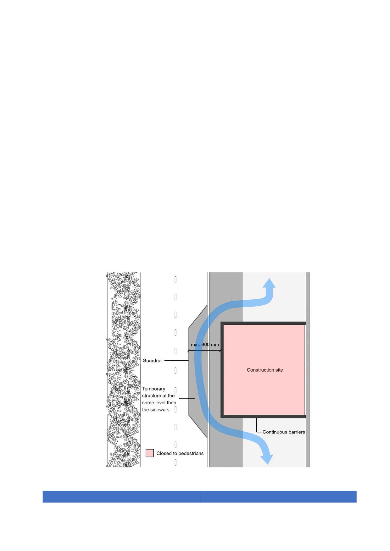
Figure 83. Alternative path in the same sidewalk
123
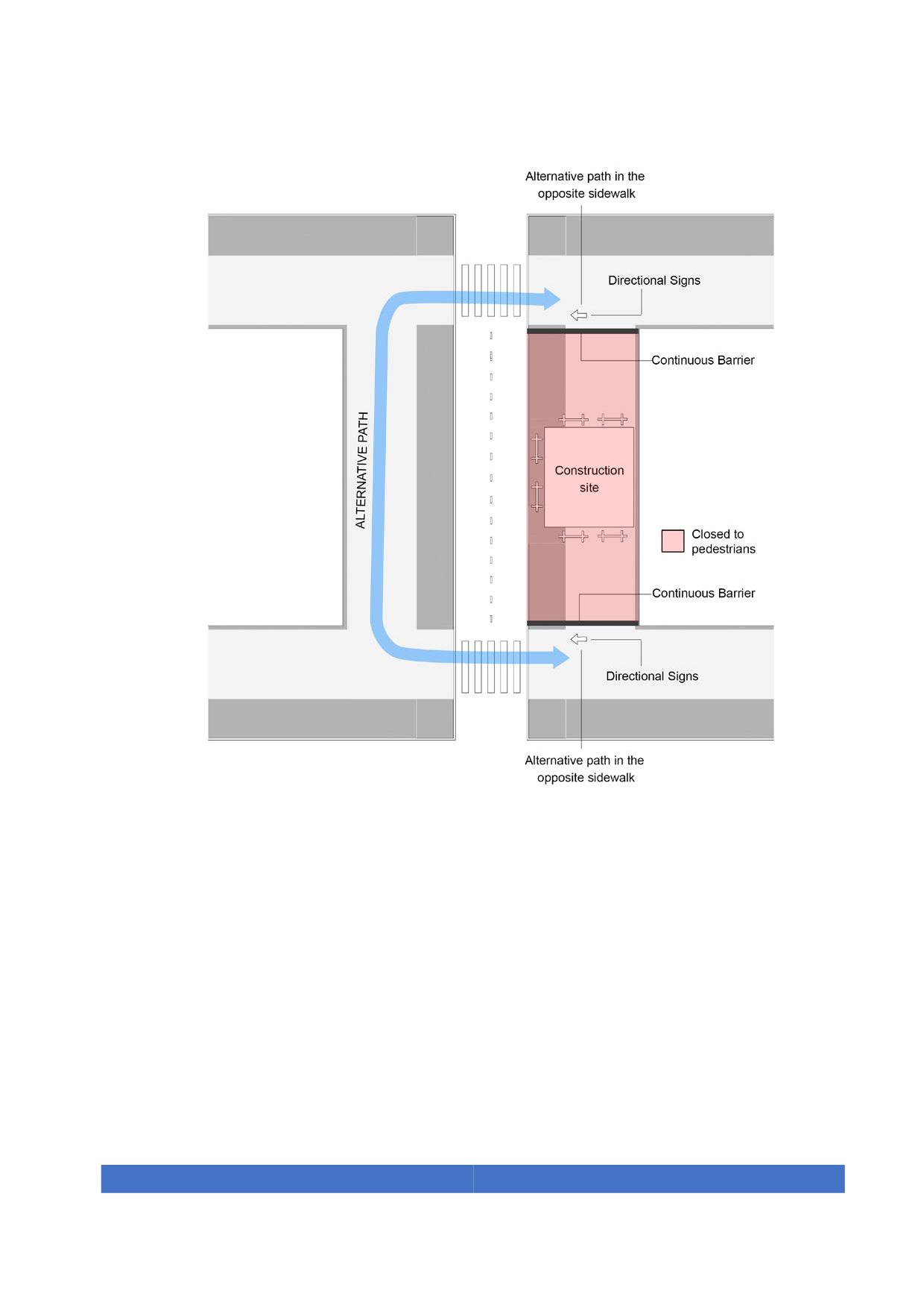
Figure 84. Alternative path in the opposite sidewalk
5. Accessible pedestrian paths shall not be obstructed during specific operations of
loading, unloading and material supply.
6. Where material and debris generated by the construction have to be stored on
the road, it shall be clearly marked and protected to ensure that it does not
constitute a danger for pedestrians or vehicles.
7. In the case of pedestrians walking over trenches protected with metal plates, the
metal structures shall have a minimum width of 900 mm, with guardrails on both
sides. Guardrails must follow the requirements of section 5.5. These metal plates
must provide a stable surface and be level with the surrounding surface.
124
6.17.1. Scaffolding
The following general criteria shall be fulfilled:
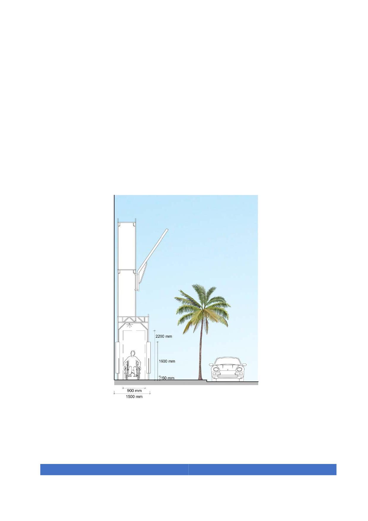
1. The temporary or alternative path shall have a minimum width of 900 mm and
headroom of 2200 mm, free of obstacles. Where there are changes in direction, the
minimum dimensions shall be 1500 mm x 1500 mm.
2. When the width of the sidewalk does not allow the installation of scaffolding, an
additional walking surface beside the sidewalk shall be provided.
3. If the road does not allow this solution the passage under the scaffolding shall be
closed and an alternative path shall be provided.
Figure 85. Alternative path under the scaffolding - frontal view
125
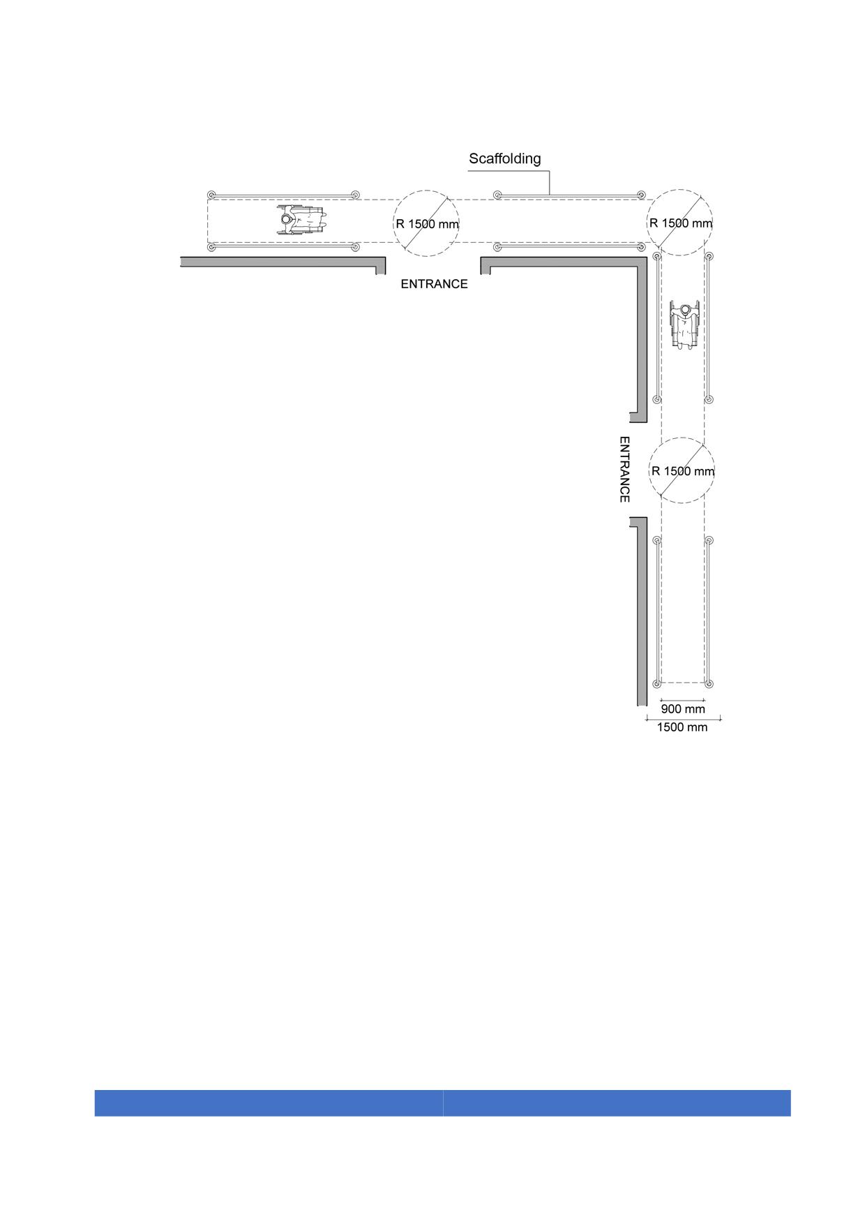
Figure 86. Alternative path under the scaffolding - plan
126
6.18. Bus shelters
A bus shelter is considered accessible when it fulfils the technical conditions specified
below:
1.
The location of the shelter does not invade the accessible pedestrian path, public
space or transportation platform.
2.
There is a path free of protruding and overhead obstacles on both sides. The path
must have a minimum width of 1200 mm.
3.
It shall be possible to manoeuvre inside the bus shelter providing a 1500 mm
diameter area, free of obstacles without interfering with any of the vehicles
manoeuvring or approaching.
4.
The minimum height of the shelter shall be not less than 2200 mm.
5.
There shall be no obstacle between the space covered by the bus shelter and the
transport vehicle.
6.
If any of the walls are glazed, they shall be marked as indicated in section 5.15.
7.
Bus shelters shall provide at least one fixed bench with the following characteristics:
• The seat height is between 430 mm ± 30 mm.
• The seat depth is between 400 mm and 450 mm.
• The backrest with a height of at least 400 mm and with armrest on one of its
ends.
8.
It shall have at least one standing support, located at a height between 700 mm and
750 mm, and separated at least 200 mm from the wall or vertical closure.
9.
It shall have a minimum average illumination of 50 lux measured at the ground level
during the service hours, and a minimum value of 100 lux at the boarding time.
10. The boarding area platform shall have a detectable warning surface as described in
section 5.3.
127
6.19. Bus signposts
A signpost shall be provided at each bus shelter. The bus signposts shall not obstruct
the accessible path.
The signpost shall be designed with the following requirements:
1. The sign is located above 2200 mm of height.
2. There are no elements that protrude below the 2200 mm height.
3. The bus information shall be provided in an area between 1200 mm and 1600 mm.
4. There is a bus line identification number with characters with a minimum height of
140 mm contrasted with the backg0round. It shall also be tactile.
5. An information number and website should be posted.
6.20. Requirements for parks, beaches and natural spaces
Benches or places to sit in parks shall be designed according to the provision of this
Code.
Information about the nearest public accessible toilets and interest points within the park
or beach shall be installed at least in every path intersection, following the parameters
for information panels described in section D.
Public accessible toilets shall be installed near the accessible path.
Supplementary paths can be used at beaches and natural landscapes where walking
would be difficult.
A temporary path is considered accessible when it meets the following technical
requirements:
1. It has a width of 1500 mm free of obstacles.
2. Whenever the natural slope of the terrain allows it, a path’s running gradient shall
not be greater than 5% and the cross-fall gradients shall not be greater than 2%.
3. It is constructed of material that has a heat transmission coefficient that allows
walking barefoot over them.
128
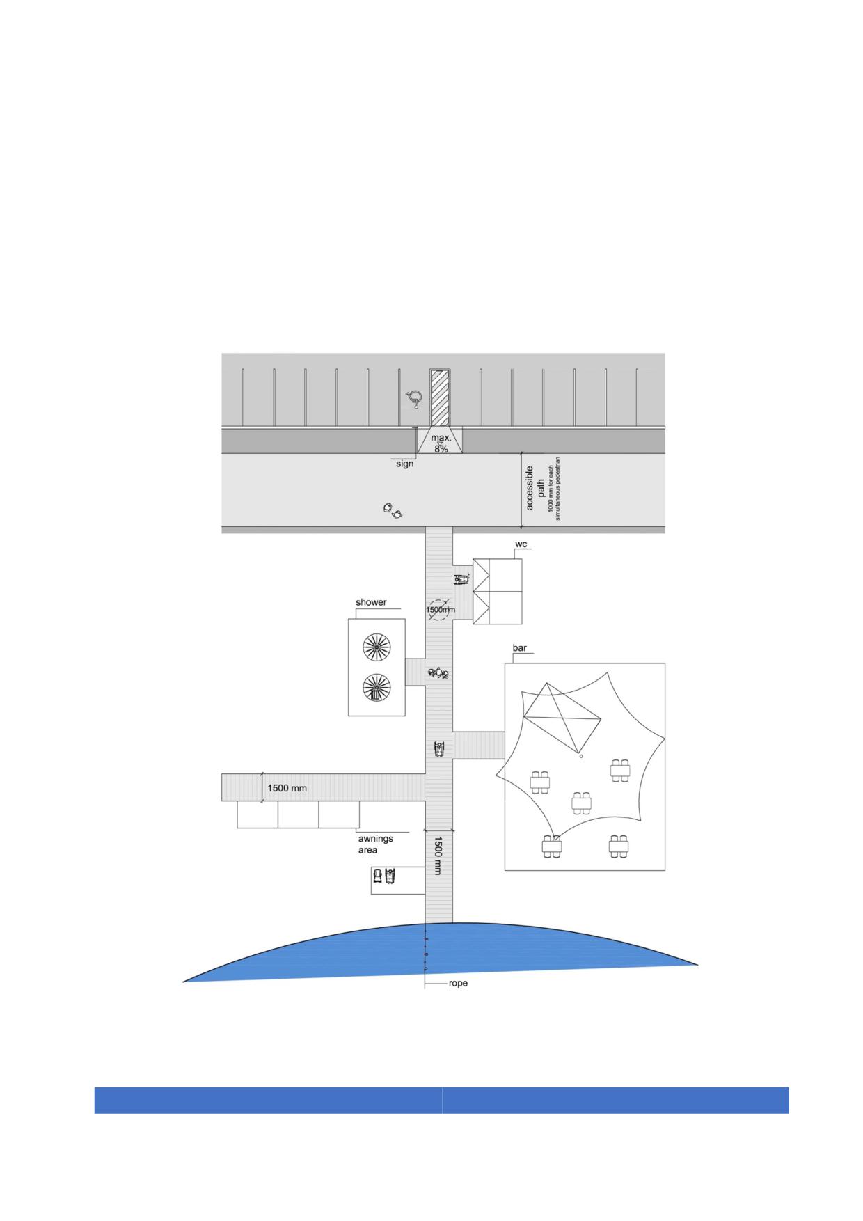
4. Supplementary paths shall reach as close as possible to the water’s edge.
5. There should be at least one accessible unit of each utility, such as toilets,
lounges, beach coffees and restaurants, showers, changing rooms, furniture,
emergency services among others. These utilities should be installed as close as
possible to each other and shall be connected by an accessible path. Access to
them shall also be via an accessible path from the beach’s access and from the
accessible path to the water's edge.
Figure 87. Path schemes connecting all beach services
129
6.20.1. Access to the water
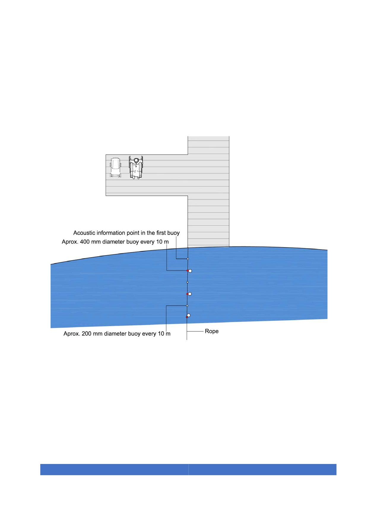
In the case of lakes and sea, there shall be a rope to help users in the accessible point
of access into the water. This rope remains floating and its length is adapted to the
specific conditions of each swimming area.
Figure 88. Orientation rope. Length will vary depending on water conditions
130
6.20.2. Outdoor showers
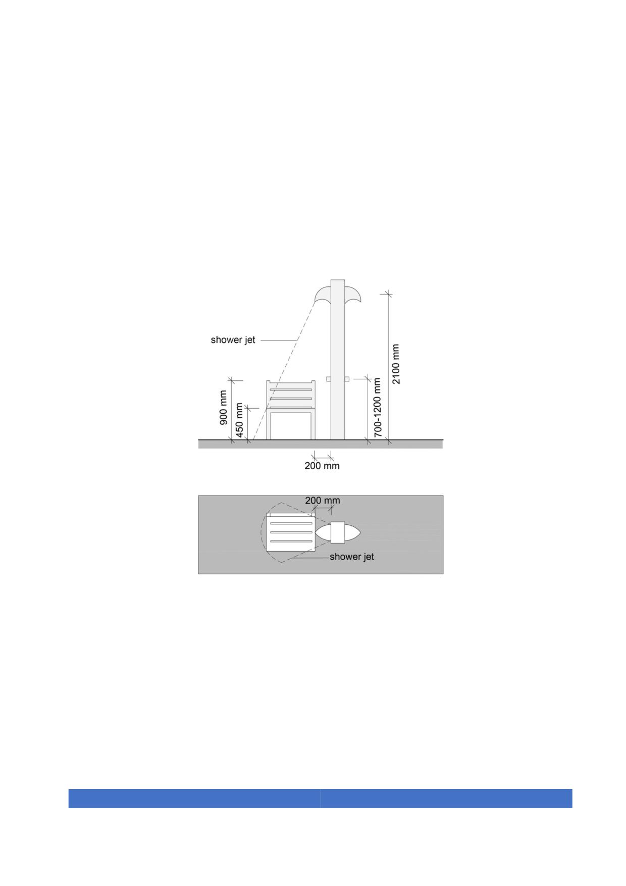
Outdoor accessible showers shall be provided at accessible beaches and swimming
pools. These shall be linked via an accessible path and interaction space. They shall be
at least 1800 mm in width and shall be provided with a bench without arms.
Shower controls shall be a button placed between 700 mm and 1200 mm and be
possible to be activated with the elbow.
Figure 89. Outdoor shower
131
6.21. Playgrounds
Playgrounds that offer a variety of different types of play options (visual, auditory and
tactile) should be provided. A playground is considered accessible when it fulfils the
following conditions:
1. It meets the basic requirements relating to accessibility of fixed accessible urban
furniture.
2. Playground surfaces shall consist of rubber or compacted sand.
3. The surface of the children play area shall be smooth & firm and free from any
sharp objects, projections etc., in order to avoid injury to the children.
4. All children regardless their functional limitations, and according to the age group
for which the playground is intended, shall enjoy and use, at least, 50% of
individual and group expected activities.
5. All materials exposed to sun radiation shall not reach temperatures that may
damage the users.
6. Materials used to design children's games; especially the sliding ones, shall not
contain plastics or metals that produce electrostatic discharges that may
deprogram hearing aids. In any case, the existing playgrounds that produce this
effect must be marked with a symbol like the ISO with explanatory text or the
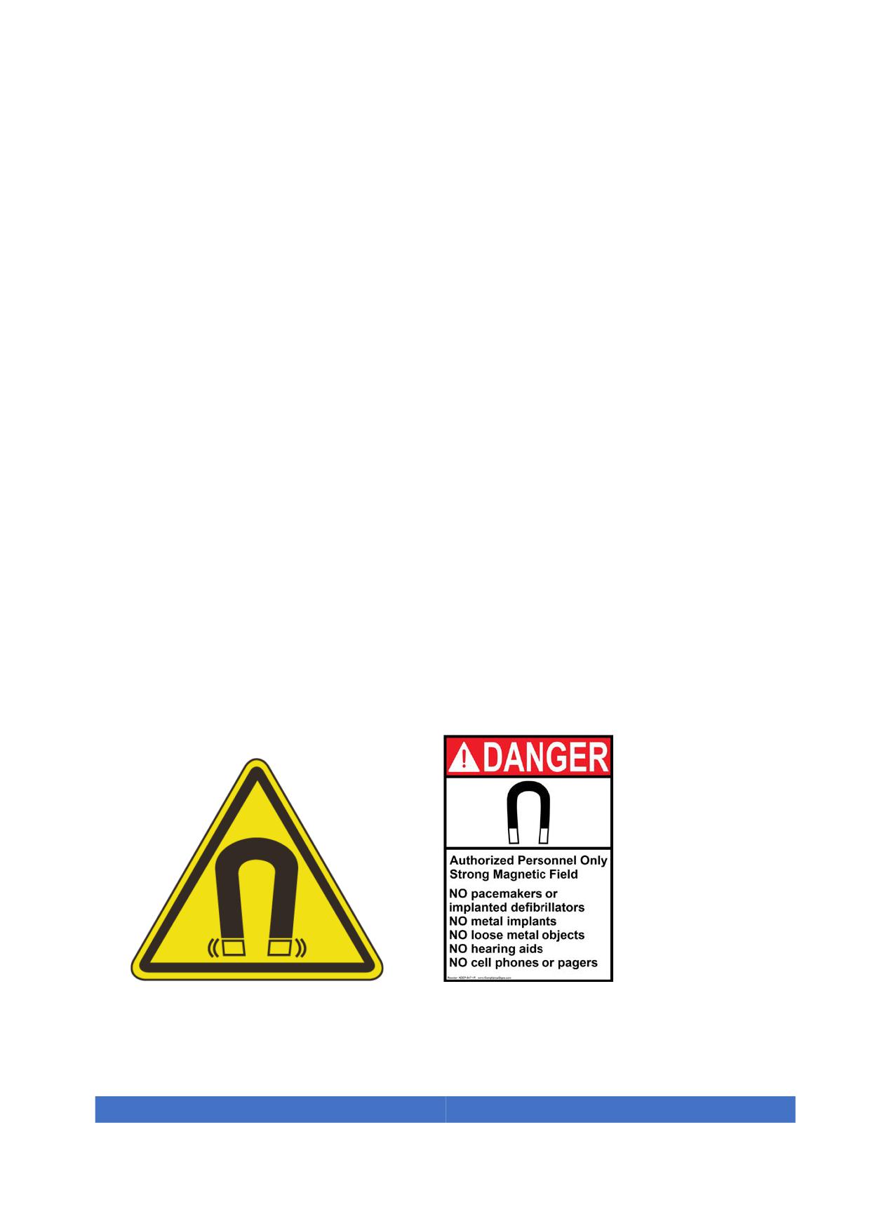
ANSI DANGER Strong Magnetic Field.
Figure 90. Example of ISO and ANSI magnetic warning signs
132
6.22. Commercial Kiosk
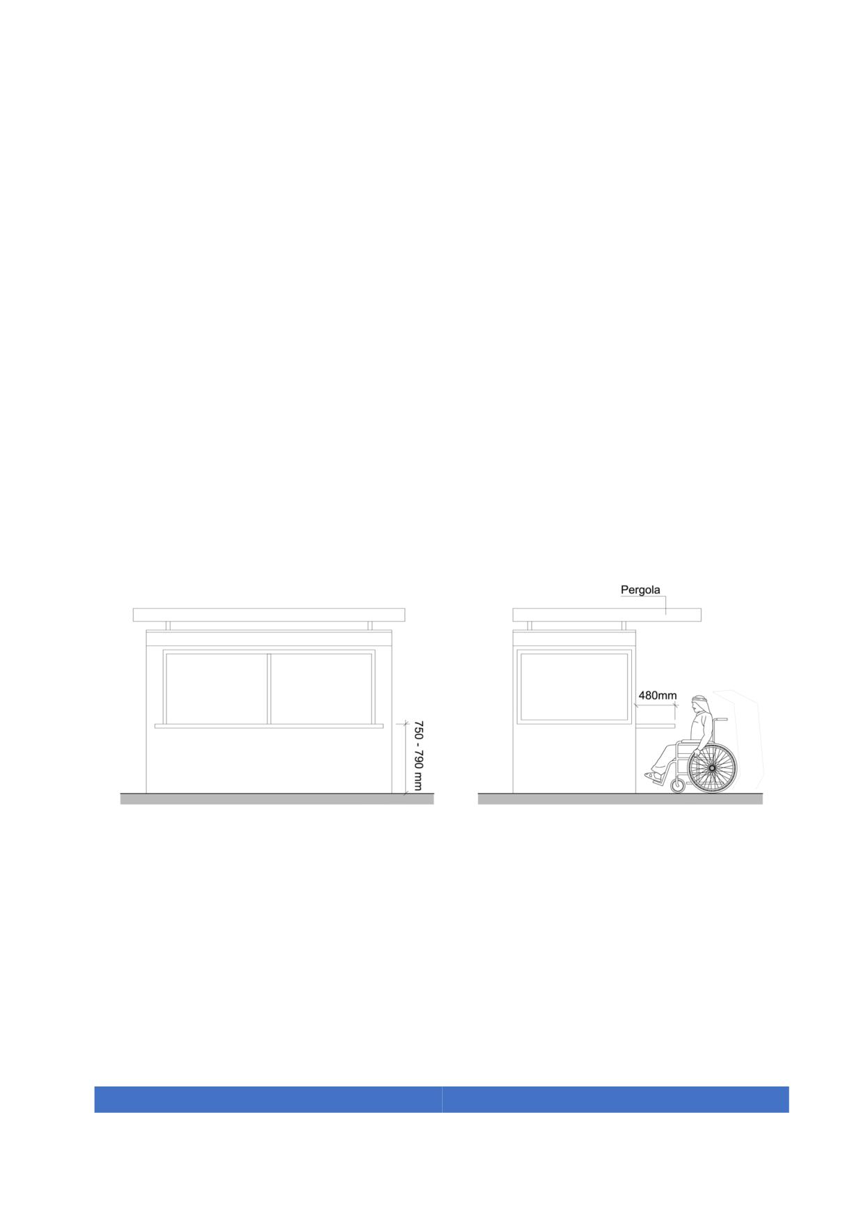
Commercial kiosks must meet the following:
1. It shall have a customer counter with a lateral or frontal interaction space.
2. Outdoors kiosks shall have a pergola in the front side.
3. This interaction space shall be linked to an accessible path.
4. It shall be equipped with a hearing enhancement system and a post indicating
such.
5. All controls shall be at a maximum height of 1200 mm.
6. All information shall be provided in audio and visual formats.
7. Visual information shall be well contrasted and in a minimum of 14 pt.
Figure 91. Example of an outdoors commercial kiosk
133
7. Buildings
All buildings shall comply with this Code. Whenever possible building façades should
be retracted in order to provide a shaded walking path.
7.1. Entrances
Entrances to buildings shall be located and oriented in such a way to ensure the
shortest distance for pedestrians between the buildings, parks and beach facilities and
public transportation modes.
An accessible path shall link the parking area, designated accessible parking zones and
the sidewalk to the main entrances of all building’s or facilities’.
The accessible path from the street or public space shall avoid stairs and ramps.
Gradients up to 2% are preferred, although up to 5% are acceptable to reach the main
entrance(s) at street level. If over 5% it should be designed as a ramp.
The accessible and inaccessible paths shall be marked with clear signage.
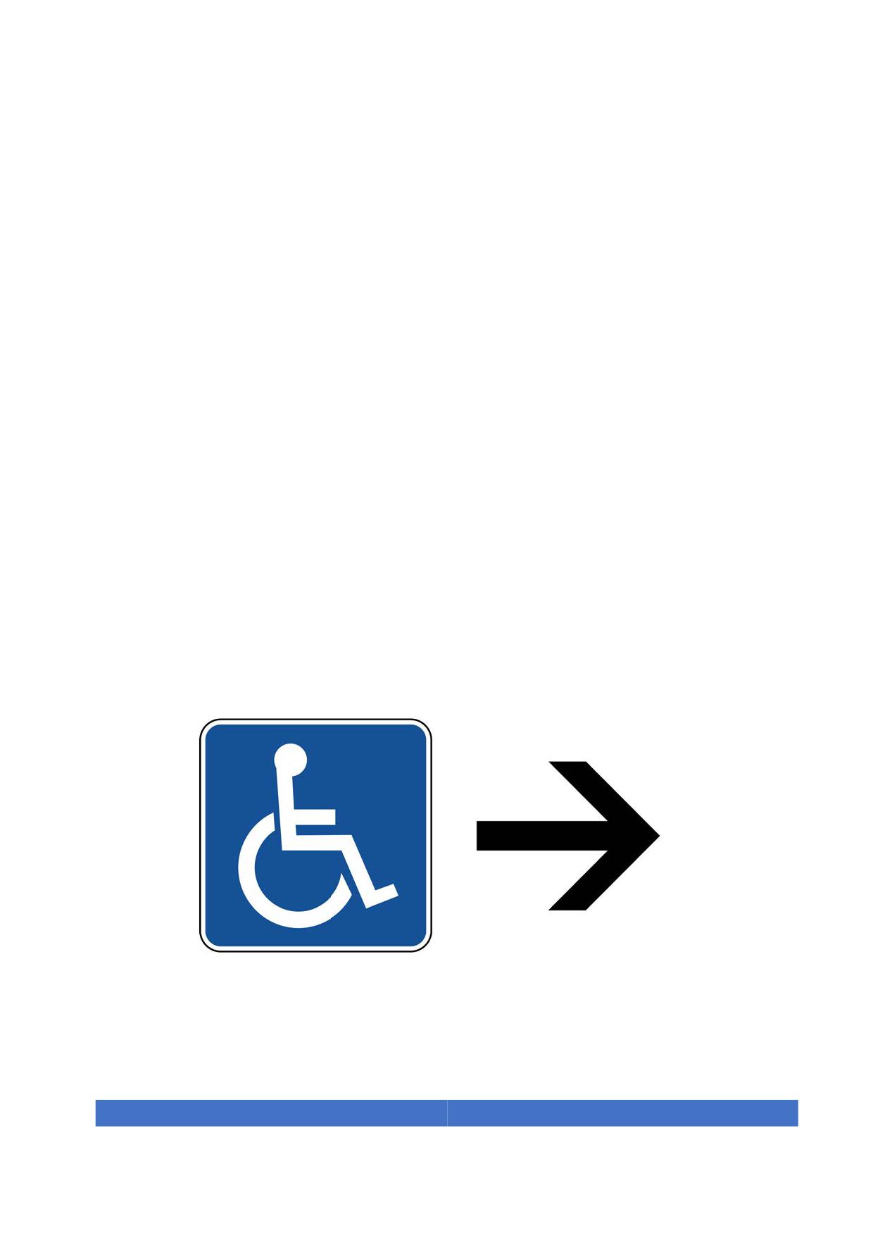
In existing buildings when the accessible door is not the main entrance door the
direction to the accessible entrance shall be marked with the International Symbol of
Access (ISA).
Figure 92. International Symbol of Access with directional arrow
134
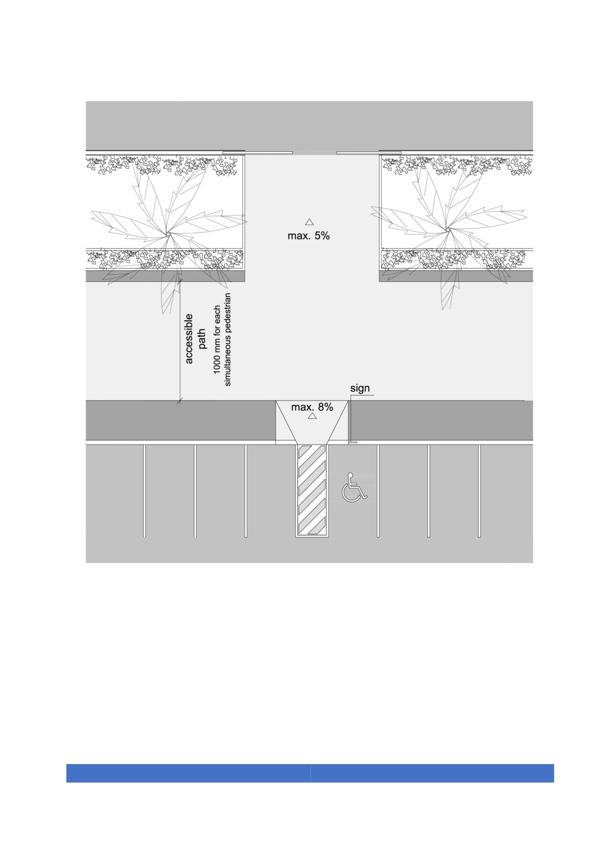
Figure 93. Direct access from parking area to building entrance
Each building entrance shall be provided with an identification number that shows the
exact address.
Near the main entrance(s) a directory as specified in section D shall display the main
departments and/or services provided in the building. This information may also be
provided by voice via a mobile application or via costumer service. An information
number and website should be posted.
135
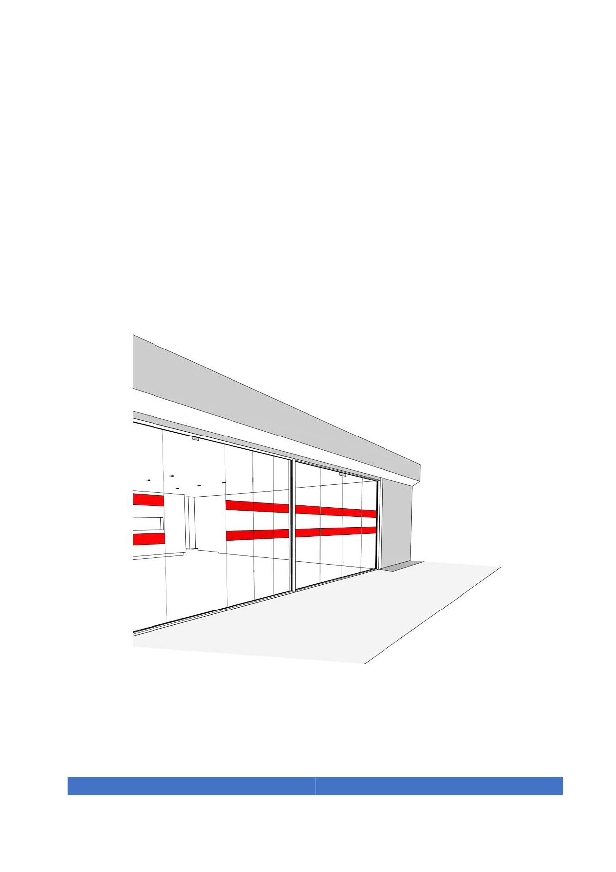
A reception desk visible from and near the entrance shall be provided in all public use
buildings.
All entrance doors must have a clear passage width adequate to the intended use of the
building and the expected number of users. Minimum dimensions are 900 mm width x
2100 mm height.
In case of revolving doors, an alternative door shall be provided,
Entrance doors shall be power assisted, according to the specification of the Doors
Section of this Code.
Doormats shall be levelled with the floor with a tolerance of ± 2 mm.
Figure 94. Building entrance
136
7.2. Access control barriers
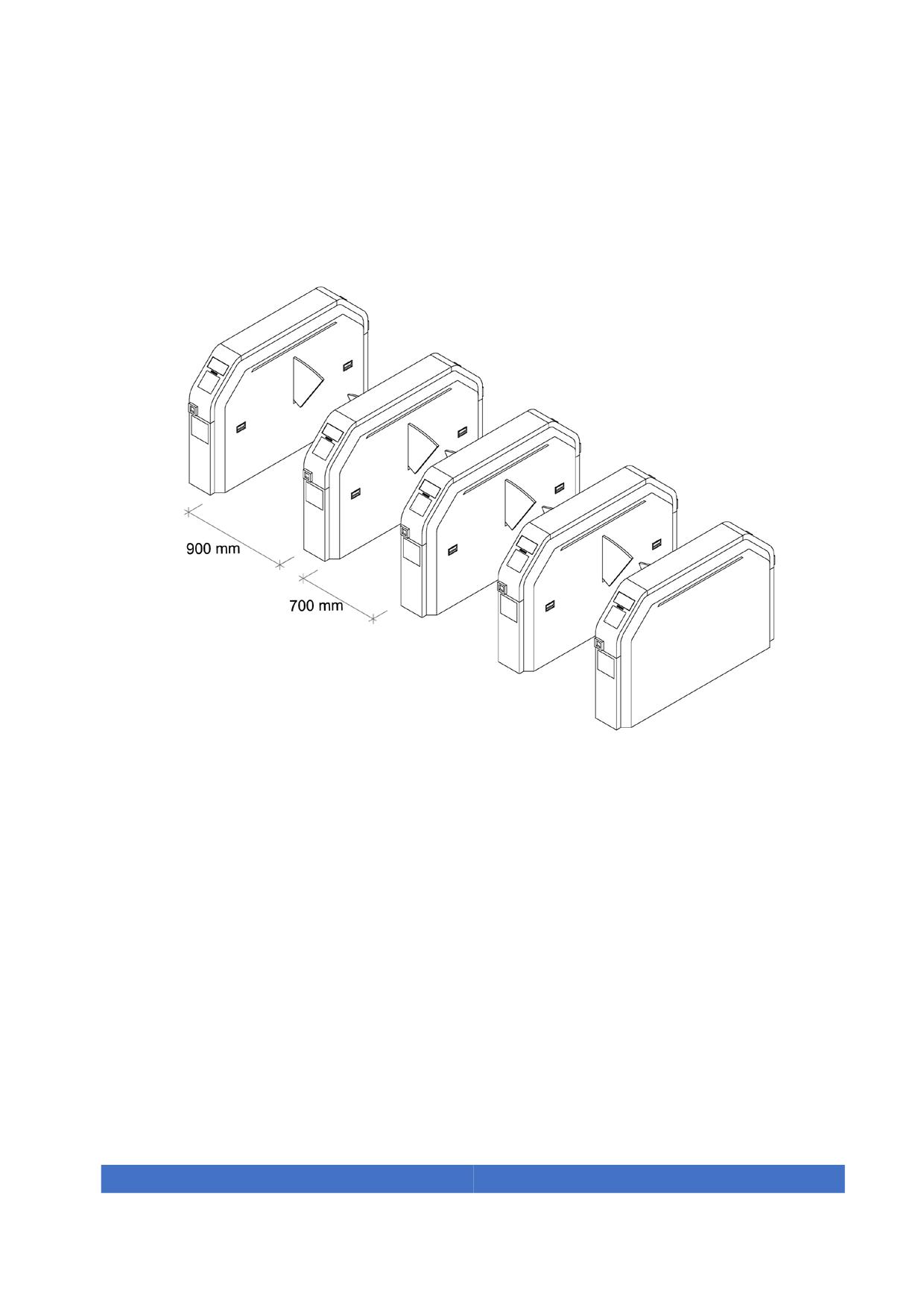
When applicable, barriers shall provide at least one entrance with a width of 900 mm.
Turnstiles is not permitted.
Figure 95. Access control barrier with at least one accessible gate
7.3. Counters and reception areas
Counters and reception areas shall provide:
1. Seating places and clear spaces to accommodate wheelchairs, scooters or strollers.
2. In reception areas enough seats for the foreseen waiting people shall be provided.
3. When providing sofas and additional regular chairs with a seat height of 430 mm
with +/- 30 mm tolerance and armrests shall be provided.
137
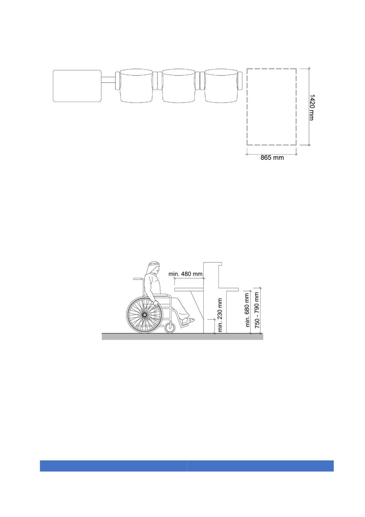
Figure 96. Seating Zone
4. Front desks shall provide a low counter between 750 mm and 790 mm and a high
counter between 950 mm and 1250 mm.
5. Under the desk board a space 680 mm height and 480 mm deep shall be provided.
These 480 mm can be included in the frontal interaction space of 1420 mm x 865
mm that shall be provided.
Figure 97. Front desk dimensions
138
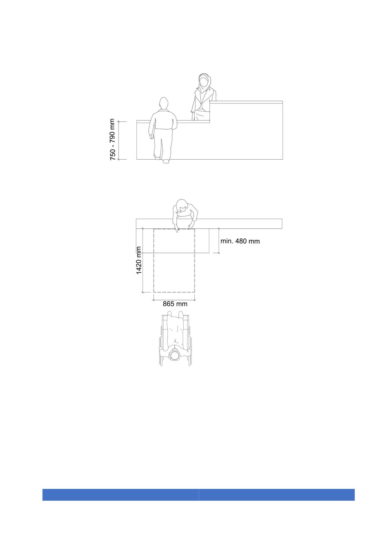
Figure 98. Front desk approaching space
7.4. Internal corridors
The width of corridors free of obstacles should be enough to allow all users passage in
both directions, according to the building’s use, considering a minimum of 1000 mm per
each simultaneous pedestrian.
Where there are direction changes (180º and 90º), the clear passage width shall allow a
manoeuvring turning space of 1500 mm diameter.
139
Floor surfaces shall be firm, smooth, stable, and level, without glare and slip resistant
avoiding vibration in wheels produced by excessive joints. Rugs and carpets should be
firmly fixed to the floor and not have a high pile.
The accessible pedestrian walking path shall present reflectance contrast with the
pavement not intended for walking of at least 30 points LRV (Light Reflectance Value)
and/or by an easily perceptible (by the foot or the cane) texture difference.
A tactile warning surface shall precede any sudden level change.
The average minimum illumination is 100 lux calculated at floor level, with a minimum
value of 60 lux.
7.5. Alarms and means of egress
Audio and visual emergency alarms shall be provided throughout the building. Visual
emergency alarms shall have a rate of 30 flashes per second. They shall be located in
places where all building occupants can see them, including toilets, accessible toilets
and family toilets. It is especially important to place visual alarms in locations where
someone might be alone.
The procedures for evacuating a building should be posted, including evacuation
procedures for persons with activity limitations.
Fire and life safety procedures should be posted in 14 pt san serif font.
Persons with activity limitations who are unable to evacuate independently may be
evacuated with the assistance of an evacuation device or evacuation chair. Fire safety
personnel can assist the person into the evacuation device and then take them down
the stairs to a safe area.
Evacuation devices should be provided on every floor over one storey. The devices
should be consistently located near the stairwell. Fire personnel should ensure that
people, including those with activity limitations, are trained on how to use evacuation
devices.
Fire protected elevators that can be used for evacuation are an alternative to the
evacuation device.
Evacuation procedures and training should be developed in conjunction with the Civil
Defence regulations.
140
7.6. Gender equality
In case of segregated use by gender of the building, the same level of accessibility will
be provided for both genders.
7.7. Storage facilities
The storage facility design shall take into consideration all the minimum spaces and
reachability recommended in Annex 3.
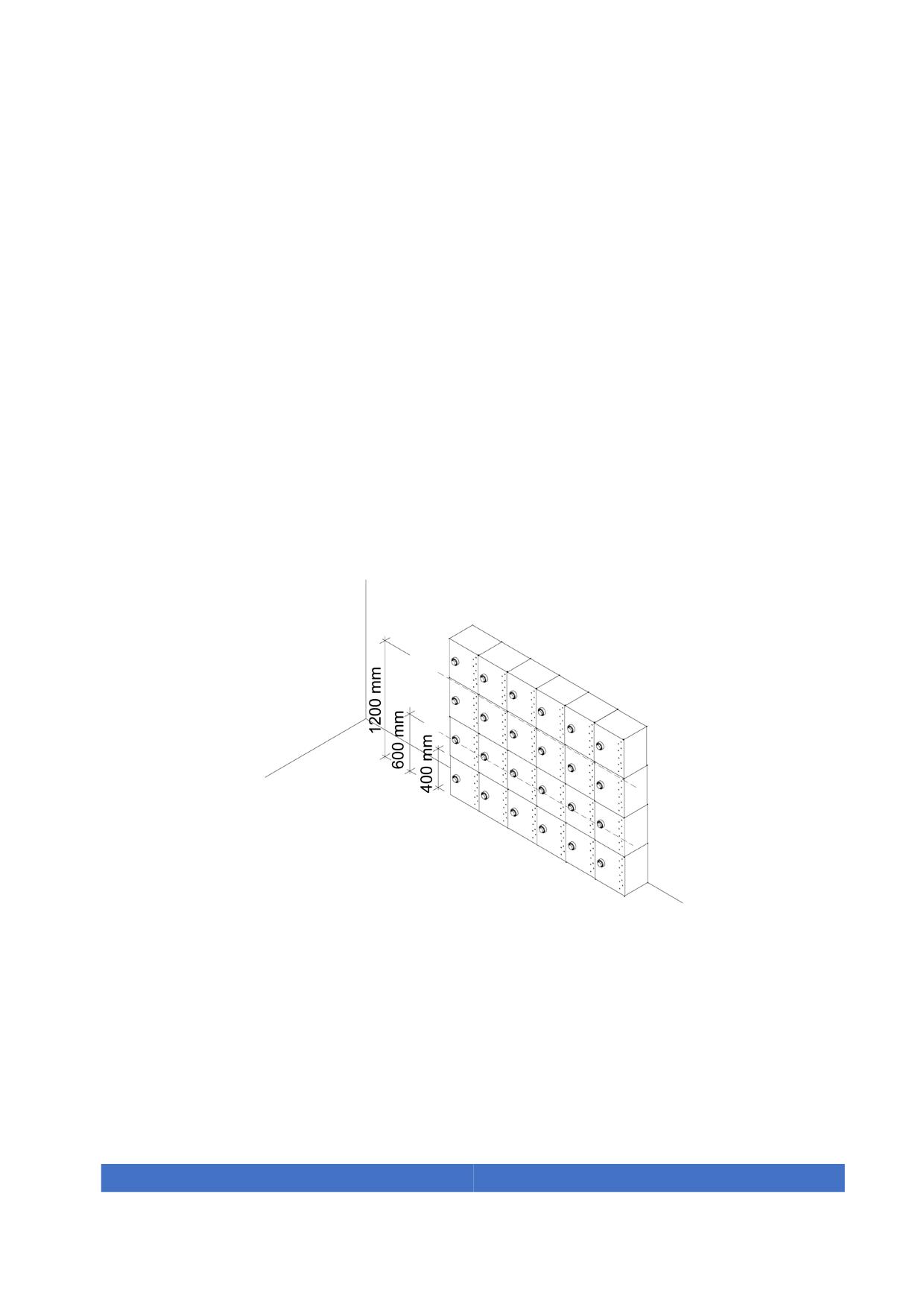
20% of shelves, boxes or lockers shall be within reaching distance for a wheelchair user
or people with short stature, between 600 mm and 1200 mm above the floor.
Lockers numbers should be well contrasted and tactile.
If benches are provided, they should be moveable.
Figure 99. 20% of boxes between 600 mm and 1200 mm
141
7.8. Accessible dressing or change rooms
A dressing or change room is considered accessible when it fulfils the following
conditions:
1. The interior corridors have a minimum width of 1000 mm. In direction changes, there
is a clear manoeuvring turning space of 1500 mm diameter outside of any opening
door space.
2. If there are lockers, the above provisions for storage facilities shall be respected.
3. Benches shall not obstruct access to lockers.
4. The approaching space for lockers, benches and furniture should have a minimum
width of 865 mm and should connect to the accessible path of travel.
5. If there are showers, at least one of every ten shall meet the criteria for accessible
showers described in this Code.
6. If there are toilets, 1 of every 10 shall be accessible.
7.9. First aid facilities
First aid facilities shall be provided with an accessible door and an accessible path to
the treatment area.
It shall contain a changing table usable for changing adults’ diapers if necessary.
7.10. Balconies
Terraces, verandas and balconies linked to accessible rooms or spaces shall be
accessible to all people including people with mobility limitations.
To ensure this requirement, they shall fulfil the following characteristics:
1. The door to the balcony shall provide at least an obstacle free width of 900 mm.
2. The balcony exterior and interior levels shall be the same.
3. Wherever it is possible the balcony doors shall be installed flush with the floor level.
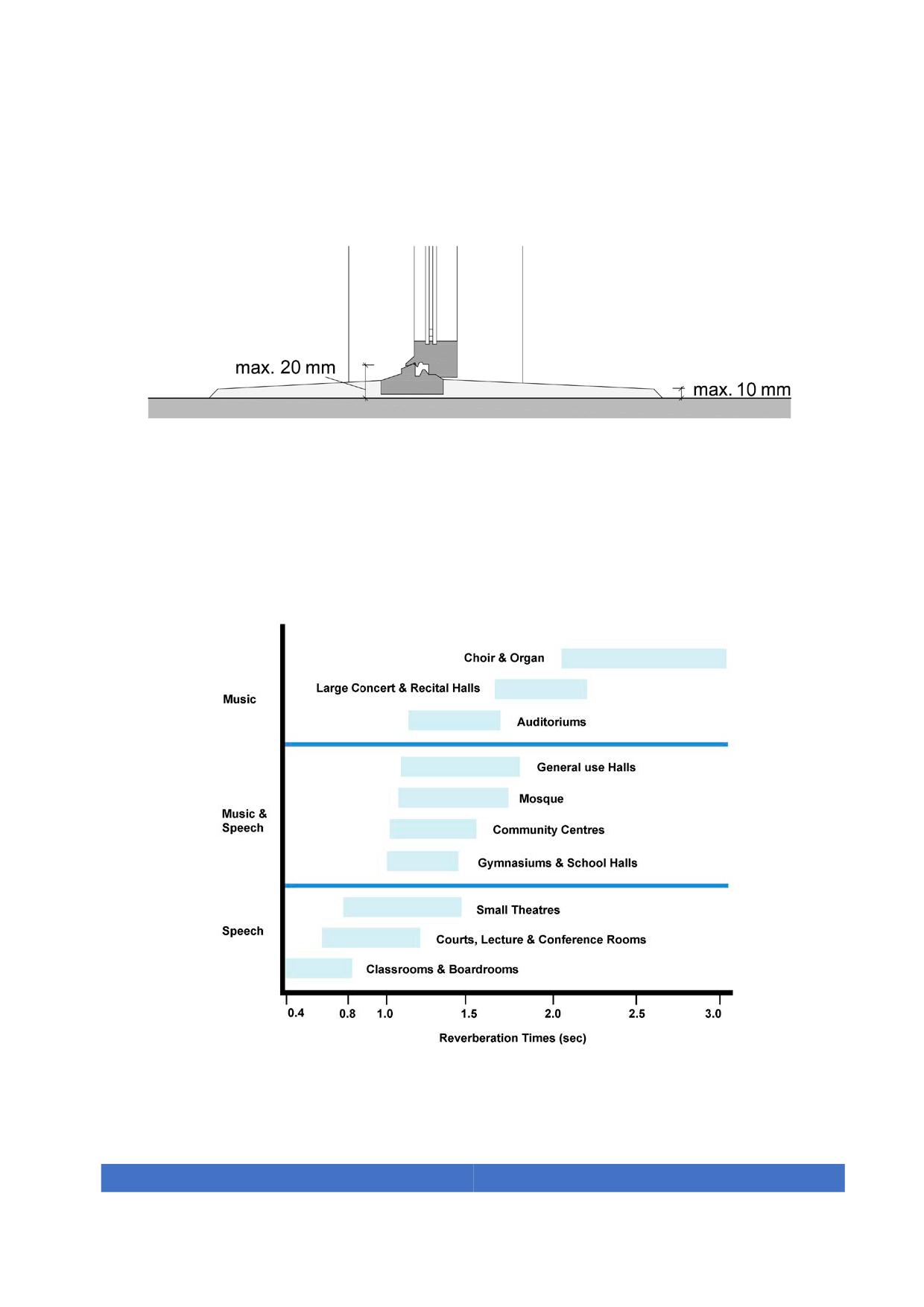
When a raised threshold is necessary it shall have a maximum height of 20 mm and
be bevelled down to a height of 10 mm chamfered.
142
4. The minimum dimensions of the balcony shall be 1500 mm x 1500 mm.
5. Walking surfaces shall be slip resistant and follow the requirements of section 5.2.
Figure 100. Maximum threshold rise
7.11. Acoustics
To ensure an adequate transmission of sound information in rooms, acoustic
reverberation levels shall fulfil the requirements of the following table:
Figure 101. Recommended reverberation times
143
Rooms shall be designed with sound absorbing surfaces to reduce the transference of
noise.
7.12. Hearing enhancement systems
A hearing enhancement system (such as an induction loop, FM or infrared) is required
to communicate with hard of hearing persons and shall be provided in the following
types of buildings: meeting rooms, auditoriums, service counters, theatres and concert
halls.
A hearing enhancement system enables sound signals to be transmitted to persons
using hearing aids without interference from backg0round noise or excessive
reverberation level.
In all meeting rooms of over 25 people, in all assembly areas and at service counters, a
hearing enhancement system shall be provided.
Hearing enhancement systems that operate using induction loops, infrared and radio
frequency are commonly used to provide enhanced level of sound.
Expert advice should be sought when selecting a hearing enhancement system
appropriate for the situation and purpose.
Where hearing enhancement systems are provided for persons with hearing
impairment, the international symbol of access for hearing loss shall be provided.
Hearing enhancement systems are compatible with language translation systems.
A sign should be posted indicating that the enhancement system is available.
7.13. Auditorium seating spaces
An auditorium seating space is considered accessible when it meets the following
requirements:
1. It is connected to an accessible path.
2. Accessible seating can be provided with either permanent or removable seating.
3. Level wheelchair spaces with dimensions shall be of at least 865 mm x 1420 mm
if approached frontally and 865 mm x 1500 mm if the approach is lateral shall be
provided.
144
4. A level manoeuvring space of 1500 mm x 1500 mm must connect to each
wheelchair space.
5. It shall be marked with the international symbol of access (ISA), whether as
permanent seating spaces or removable seating areas.
6. Both the surface of wheelchair spaces and the clear manoeuvring space are
level having a maximum longitudinal gradient of 1%.
7. For facilities with fixed seats, designated wheelchair spaces shall be arranged
into groups of 2. Each group of wheelchair spaces must have at least an equal
number of fixed seats.
8. If the designated wheelchair spaces include removable or foldable seats, the
conversion process shall be quick and easy.
9. Wheelchair spaces shall be provided in all auditorium-seating sections.
10. The number of reserved wheelchair spaces shall comply: 1 reserved wheelchair
space for every 50 seats or fraction thereof and beyond 500 seats, 1 more for
every 100 seats or fraction thereof.
11. In theatres, cinemas, conference rooms, auditoriums and all the facilities where
people are expected to sit or wait, it is recommended that some seats should
have a space for service animals near the owner.
12. A space at the front of the hall or room where a sign language interpreter can be
easily seen shall have an independent overhead light.
13. A sufficient number of designated accessible seats for people with hearing
impairments should be provided in front of the sign language interpreter.
14. Aisle seats and its adjacent shall have foldable armrests.
145
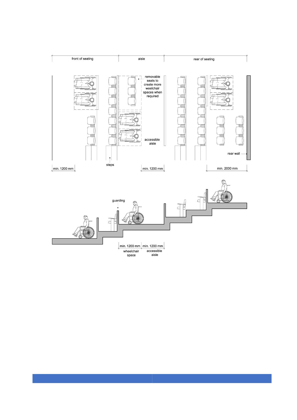
Figure 102. Example of reserved seating spaces in an auditorium
7.13.1. Stages and backstage
Stages shall be accessible to everyone via a ramp or lift. In an exceptional case a lift
platform can be provided to make the stage accessible. The lift shall fulfil the
requirements of section 5.10.1.
Buildings for public events with a capacity of over 100 spectators shall provide an
accessible backstage. This accessible backstage area shall also provide an accessible
toilet, including a shower, a change room and a space with an accessible mirror.
146
The path between the backstage and the stage shall comply with the requirements of
accessible paths.
7.14. Swimming Pools
Swimming pools and other bathing pools for public use shall have at least one
accessible means of entering the water and an accessible path linking the pool with the
facilities and the common areas.
For private use swimming pools like in condominiums the accessible provisions shall be
followed if a tenant requires it.
The floor surface of the swimming pool areas shall comply with the section 5.2.
If there is information messaging, the facility shall provide screens and loudspeakers,
and the information shall be provided in two alternate formats simultaneously. The
technical criteria of the messages displayed are described in section D.
If an accessible path for the entrance to the pool cannot be provided, a ramp or an
assisted elevation chair or hoist shall be implemented.
Other requirements:
-
Safety ladder
-
Underwater illumination if night use is foreseen.
-
Depth scale following the signs requirements presented in section D.
-
It should be connected to an accessible change room for each gender.
147
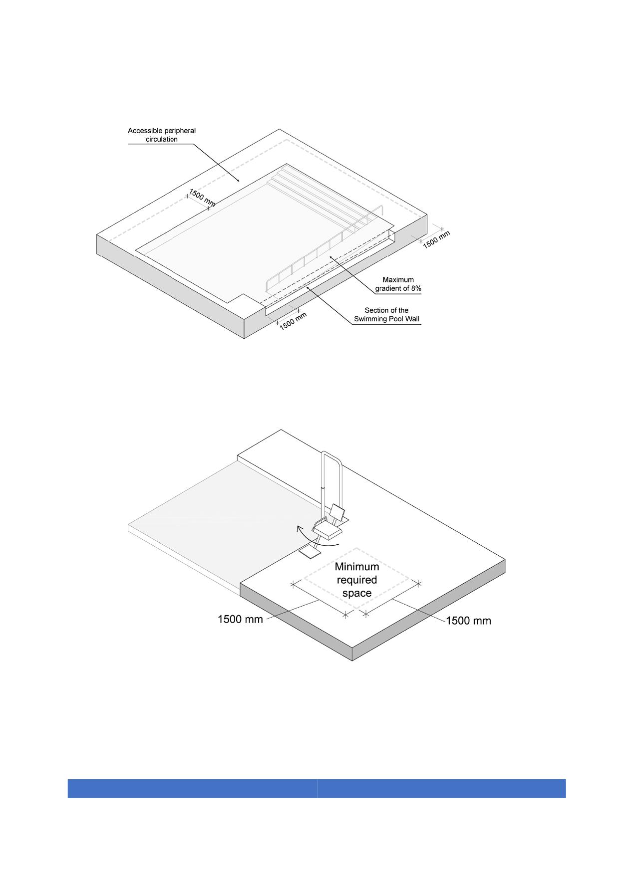
Figure 103. Swimming pool with access ramp
Figure 104. Swimming pool chair lift
148
7.15. Mosques and prayer rooms
Mosques and prayer room shall fulfil the following requirements:
1. An accessible path shall connect the public space with the building and the
different rooms among them. An accessible entrance shall be provided.
2. A clear area shall be provided at the entrance to prevent shoes from blocking the
accessible path. This shall be complemented with a KEEP CLEAR mat if the clear
entrance is not guaranteed.
3. Seats shall be provided at entrances and at other locations where people are
required to remove their shoes.
4. Seating should also be provided within the prayer hall to accommodate people who
cannot bend to pray.
5. The route to the designated area crossing the prayer hall’s carpeting shall have low
pile carpeting.
7.16. Other temples and praying rooms
These buildings and rooms shall guarantee the same accessibility requirements that
shall be observed in all public use buildings regarding circulation, lighting and
wayfinding in this Code.
7.17. Accessible hotel rooms
Hotels shall comply with all elements in this Code. Hotel rooms shall fulfil the following
requirements:
1. At least 10% of hotel rooms shall be accessible as well as all common spaces in
the hotel premises.
2. An accessible toilet with grab bars, an accessible shower and vanity shall be
provided in compliance with this Code.
3. Half of the accessible hotel rooms shall provide roll-in showers while the other
half shall provide bathtubs following the requirements of the drawings below. In
both cases an alarm string shall be provided.
4. The accessible rooms shall be provided with acoustic and visual fire alarms.
149
5. Controls shall be placed at a height between 700 mm to 1200 mm except for the
ones to be used from the bed. These should be placed comfortably in reach of
occupants. Electric outlets shall be provided at a height between 400 - 1000 mm.
6. A clear route shall be provided to the bed with a minimum clear space of 1500 x
1500 mm beside the bed.
7. The bed shall have a maximum height of 500 mm.
8. The accessible rooms shall be provided with acoustic and visual fire alarms as
well as an audible doorbell.
9. A dressing mirror where the user can see his or her reflexion from 250 mm to
2000 mm shall be provided.
10. Shelves and drawers shall be provided between 700mm to 1200 mm from the
floor, and whenever possible a clothes hanger should be placed at 1100 mm
from the floor.
11. A clear route shall be provided to the bed with a minimum clear space of 1500 x
1500 mm beside the bed out of any furniture.
12. A minimum of illumination of 200 lux shall be provided by at least one lighting
fixture in the room.
13. Connecting rooms shall have accessible doors.
14. A viewing device should be provided in the door at a height of between 800 mm
- 1000 mm.
15. Clothes hangers and hooks should be provided at a maximum height of 1100
mm.
16. There shall be no change in level or lip in the washroom, including at the shower.
17. Reception desks shall provide a lower counter to assist people of short stature
and people using wheelchairs. An approaching space in front of the reception
desk has to be provided for wheelchair users.
150
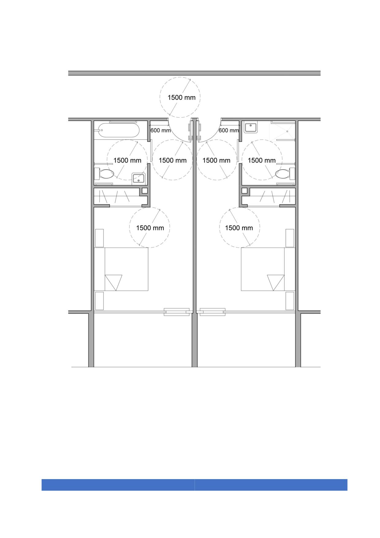
Figure 105. Example of two accessible rooms, one with roll-in shower and the other
with accessible bathtub
151
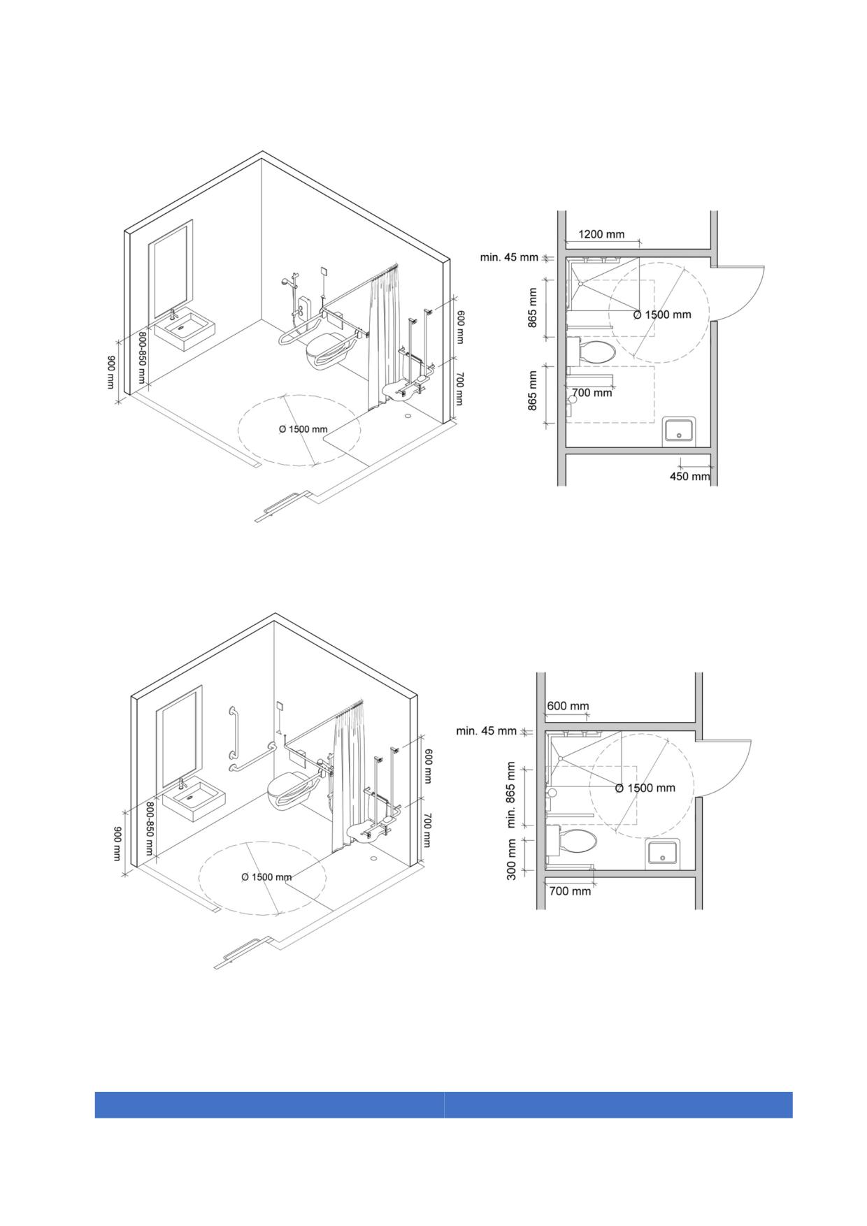
Figure 106. Example of toilet with approaching space in both sides and roll-in shower
Figure 107. Example of toilet with approaching space in one side and roll-in shower
152
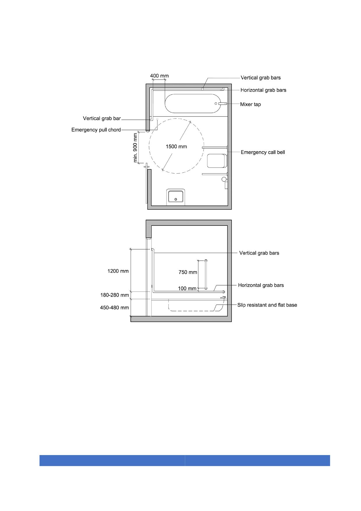
Figure 108. Accessible bathtub with bars’ dimensions
153
7.18. Dining rooms
Dining rooms shall fulfil the following requirements:
1. An accessible path of travel shall be provided to at least half of the dining areas.
2. Illumination of at least 100 lux shall be provided in at least 10% of the dining
room.
3. Sound reduction materials should be incorporated into dining rooms.
4. The floors, and walls shall be made of a smooth & washable material that is
easily cleaned and non-absorbent.
5. At least 10% of the tables shall comply with the dimensional criteria for tables
described in section 5.20 and shall be connected with an accessible path. At
least 900 mm of clear width shall be provided to reach of these tables.
6. Where self-service aisles or tables are provided, all food, condiments and cutlery
shall be located between 900 mm and 1200 mm from the floor.
7. A clear passage of a minimum of 900 mm should be provided to all food service
areas, condiments and utensils.
8. Space for children strollers and mobility devices shall be provided.
9. At least 10% of seats shall be movable.
154
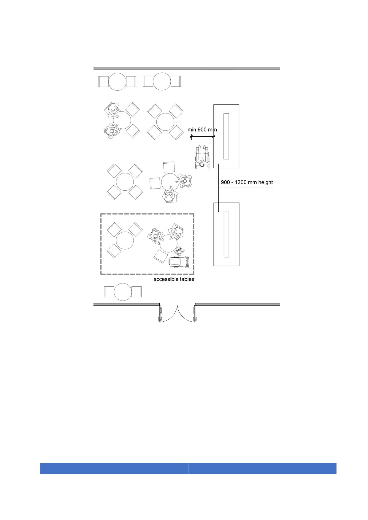
Figure 109. Example of an accessible dining room
7.19. Housing
7.19.1. Required accessibility in existing residential buildings
Multi-family buildings must have an accessible path for access to each of the
residences and between each of the residences.
There shall be a level entrance to all residences.
In residential buildings, a video doorbell shall be provided.
155
Multi-storey buildings shall have an elevator to create an accessible path from the
outside to the entrance of each residence.
7.19.2. Required accessibility in new housing buildings
The following dimensions and characteristics provides better quality of life for tenants
and allow a low-cost conversion of any house to be accessible in the future if one of the
tenants or family members has a disability.
These dimensions are compulsory for all new housing buildings:
1. The entrance and internals doors shall provide a free passage of at least 900 mm.
2. Wall mounted switches shall be between 900 mm and 1200 mm and be located a
minimum of 600 mm from any corner.
3. Corridor width shall be at least 1000 mm and 1500 mm in direction changes.
4. Manoeuvring space inside kitchen, bathroom, living room and one bedroom shall be
at least 1200 mm free of door openings and fixed elements, and 1500 mm where
turning is required.
5. The bathroom shall contain at least a bathtub or roll-in shower, sink and toilet.
6. In houses with more than one level, at least the kitchen, one bathroom and one
living room or bedroom shall be accessible from the entrance door.
7. Interior stairs width shall be at least 1100 mm wide.
156
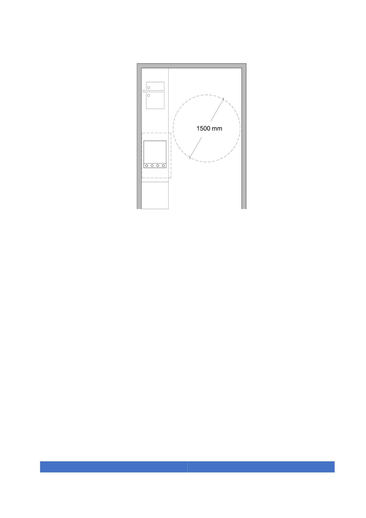
Figure 110. Manoeuvring space in an accessible level kitchen
In villas and apartments of two or more levels a vertical platform is allowed. See section
5.10.1.
7.20. Health and social care buildings
Health and social care buildings shall meet all requirements of this Code.
Large corridors and elevators in health and social care buildings shall fulfil the following
requirements:
1. Besides the general requirements mentioned in the different sections of this Code
regarding corridors and elevators, health and social care buildings’ horizontal and
vertical circulation should be designed to ease the movement of beds and gurneys.
2. This is particularly important at changes of directions and at access to rooms from
corridors, and in the dimensions of the elevator cabins. Elevator cabins with doors
on adjacent sides should be avoided.
3. Corridors shall have handrails in all their lengths, according to the criteria set in this
Code.
157
4. Protected sections by firewalls shall be provided according to Dubai Civil Defence
regulations:
• In order to ensure a safe evacuation of buildings in case of fire, different sectors
shall be separated with fire protection walls and doors.
• These sectors shall be designed with a sufficient fire resistance time, to keep the
users safe, while fire is extinguished or to evacuate the building.
5. All patient rooms in health and care buildings shall have an accessible toilet with
shower.
6. At least one accessible toilet room for each gender shall be provided in each
department or area.
7.21. Recreation buildings and amusement parks
In recreation buildings and amusements parks, the following requirements shall be
fulfilled:
1. Queue management shall be implemented:
• When queuing is required to enter or use a facility, a priority line shall be provided
for people with functional limitations.
• Moreover, when people are standing in line, signs and sound announcements
should inform them of the expected time to enter in the facility. Seating places
shall be provided for people that cannot stand in a line. The number of seats will
be defined according to the expected age and number of users.
2. When the nature of the facility requires seating places, an adequate number of
accessible seating spaces shall be provided. These seating spaces have to follow
the requirements of auditorium seating spaces in section 7.13.
3. Amusement facilities should ensure the equal use for a maximum number of people
to the highest extent possible.
4. In the case of providing different amusement facilities in the same recreational
building or amusement park, the majority of them shall be accessible for a large
number of users.
5. Depending on the facility dimensions, wheelchairs or other personal mobility devices
shall be available at the users’ disposal.
158
7.22. Cultural buildings, libraries, museums and exhibition rooms
Cultural building, libraries, museums and exhibitions shall comply with all components
of this Code.
The content in cultural buildings, libraries, museums and exhibition rooms shall fulfil the
following requirements:
1. Lights, smells, sounds, colours and other multi-sensorial elements can be used to
assist visitors of cultural buildings, museums and exhibition rooms as different users
can perceive information through different senses.
2. The exhibitions should be designed where exploration, discovery and enjoyment of
different sensorial experiences are provided.
3. In museums, exhibition rooms or in any cultural buildings where an exhibition is
displayed, audio guides should be provided to explain, guide and assist the visitor
during the exhibition and induction loops shall be provided when acoustic
information is provided.
4. Displays should visible at a maximum height of 1000 mm.
5. Signage shall be at least 14 pt and well illuminated.
7.23. Theatres, cinemas, conference rooms and auditoriums
Theatres, cinemas, conference rooms and auditoriums shall fulfil the following
requirements:
1. In the case of performances containing audio (cinema, opera, conferences, etc.),
subtitles and/or sign language should be provided for people with hearing
impairments.
2. In the case where the performance contains action (movies, theatre, opera, etc.), an
audio description system should be provided for people with visual impairments.
3. Accessible toilets should be located close to seating areas and in no case further
than 150 meters.
159

7.24. Public administration buildings
The area of the reception desk where the induction loop is installed shall be marked
with the hearing access logo. As shown in the drawing below the sign consists of an ear
with a line through it, accompanied by a ‘T’ in the lower right side of the sign.
Figure 111. Induction loop sign
7.25. Education buildings
Education buildings shall meet all requirements of this Code.
Education buildings shall fulfil the following requirements:
1. In school entrances an accessible path segregated from buses circulation shall be
provided.
2. There should be an accessible path from the bus yard to the school entrance.
3. Seats with different characteristics should be provided dependent on the students’
needs. Space flexibility shall be ensured to guarantee that places for wheelchair
users, left handed users, people of big body shapes and mobility, breathing or
communication accessories can be provided.
4. Seats at desks shall be removable and the dimensions of the table shall allow the
use of people using wheelchairs. Seats and tables shall follow the requirements and
dimensions of section 5.20.
160
5. In children’s schools and nurseries toilets and furniture with the appropriate height
shall be provided.
6. Students using assistive devices such as computers or optical character recognition
systems, among others, need electrical plugs near their seats. These electrical plugs
should be provided as close as possible to the person’s seat and the cables
between the device and the plug shall not obstruct the corridors.
7. The classrooms shall be well illuminated.
7.26. Garage and parking buildings
Garage and parking buildings shall fulfil the following requirements:
1. Wayfinding signs shall indicate the accessible parking places.
2. Wayfinding signs shall be provided at any directional change option inside the
parking, and should use the symbols and colours of each area and floor to help
people find their cars, toilets and exits.
3. Wayfinding and signage shall follow the communication accessibility criteria of
section D.
4. Floor painting contrasted 30 points of LRV with the vehicles path shall be provided to
identify the pedestrian paths.
5. In large parking areas with several pedestrian exits, accessible parking places
should be distributed near each exit. The distribution of accessible parking has to
ensure that all accessible parking spaces are not located in the same area and has
to guarantee short distances from the parking spaces to the pedestrian exits.
6. Wayfinding signs shall indicate the accessible parking places.
7. Accessible parking places shall follow the criteria of section 6.13.
7.27. Industries and laboratories
All industries and laboratory facilities where people with disabilities may work shall be
accessible and the working places adapted individually to each employee with a
functional limitation.
Work places must ensure that there are no disadvantages for people with disabilities in
the course of performing their daily duties.
161
7.28. Undefined use buildings
When designing a new building or part of a building with an undefined final use, the
architect or engineer should take into account the possible future use, possible
distribution changes or possible partitions of the building, guaranteeing that in all cases
accessibility requirements will be followed.
In addition to basic accessibility characteristics, building spaces should have the
possibility to be easily adapted to the needs of different users during the building’s
lifespan, particularly housing.
7.29. Facilities for service animals
The following recommendations should be considered in places where there is a
possibility of people with service animals:
1. In theatres, cinemas, conference rooms, auditoriums and all the facilities where
people are expected to sit or wait it is recommended that some seats should have a
space for a service animal near their owner.
2. In large buildings, such as shopping malls, leisure or entertainment facilities, and
mass transport facilities it is recommended to provide a relief facility for assistance
animals.
3. The relief areas shall not be directly connected to spaces used by persons but shall
be connected to the accessible path of travel.
4. The relief facility should have a minimum dimension of 3000 mm x 4000 mm and
should be surrounded by a 1200 mm high fence. The entrance should be easy to
operate and to find by a person with visual impairment. Moreover, the surface should
be concrete with a smooth finish to assist in cleaning, with a cross fall of 3,5 % to
assist in drainage.
5. It is recommended to provide a waste bin and a supply of plastic bags close to the
entrance.
6. The service animal facility should have an accessible sign saying “For Service
Animals only”.
The facility should be regularly cleaned and well maintained.
162
7.30. Accessible emergency provisions
Persons with disabilities shall be provided with an equal level of emergency protection
as others.
In addition to the accessibility provisions for buildings required in this Code, the
requirements for emergency and egress issued by Civil Defence shall be fulfilled.
163
164
Section C
Accessible Transport
165
Section C - Accessible Transport
8. Planning before the trip
Trip planning is the first step in the travel chain. Before starting a trip, a traveller needs
to acquire all the necessary information from origin (O) to destination (D) in order to
complete a timely, convenient, comfortable and safe journey in three stages:
• Before starting a trip
• During the trip, and
• Ending the trip (exit and arrival)
To meet the requirements of persons with functional limitations a variety of information
and communication shall be conveyed in various media: print in text or symbols, audio,
visual, haptic, touch and data conversion formats.
The necessary information includes identifying where to obtain information, reading the
information, identifying the travel route and mode of transport, the frequency and level
of service, the number of transfers encountered, the costs and method of fare payment,
baggage handling, security screening, and landmark identification.
Travel information is essential for all travellers, in particular for persons with vision,
hearing and intellectual disabilities. Alternative formats in audio, visual and tactile are
required to address their requirements.
8.1. Accessible websites
All websites that provide information to travellers shall comply with the international web
access AA level of W3C standards.
8.2. Apps for accessibility
1. Apps shall be easily usable by residents and visitors, for persons who are blind in
audio and tactile formats, with font enlargement for vision impaired; in text format for
persons who are deaf/hearing impaired, and in audio, symbol and text formats for
persons with intellectual impairments.
2. All applications that provide information to travellers shall comply with the
international web access AA level of W3C standards.
3. All applications shall be available in different languages and symbols.
166
4. Print shall be in large 14 pt sans serif fonts, and in Braille if required.
5. Telephones shall be accessible in audio, and be compatible with hearing aids. Text
options should be available for people who are deaf.
8.3. Maps
1. Maps shall be in high colour contrast, non-glare, with a minimum of 14 pt fonts and
sans serif characters.
2. Red and green colours shall be avoided.
8.4. Terms of carriage
Terms of carriage should include:
1. Size of parcel/luggage allowed on-board vehicles:
• First piece: Length 810 mm; Width 580 mm; Height 300 mm,
• Second piece: Length 550 mm; Width 380 mm; Height 200 mm.
2. Service animals and comfort animals are allowed.
3. Allergy considerations shall be observed.
4. Non-smoking policy shall be applied in all vehicles and stations.
5. No food consumption is allowed in vehicles.
6. Use of cell phone and other electronic devices (MP3, etc.) on-board vehicles and in
stations can be used only if the privacy of fellow passengers is observed.
8.5. Fare structure & ticketing
1. The universal accessible fare structure shall be based on a two for one fare policy,
and discount rates for travellers with disabilities.
2. The provider shall issue a certificate on eligibility.
3. The same discount rates shall apply to foreign visitors with disabilities.
167
4. A person should be able to purchase all fare products using distance based media
(e.g. web services).
8.6. During the trip - in station
In station information is important for all travellers in order to be able to navigate in a
seamless trip chain. The information required includes wayfinding, counter services, the
time of day, the identification of vehicles, the arrival and departure times at stops, the
location of washrooms, food services and the ticketing systems.
8.6.1.
Signage
Signage shall follow the provisions for wayfinding, Section D of this Code.
8.6.2.
Ticketing & fare structure information
1. Automatic ticketing machines shall be accessible for persons using wheelchairs and
mobility scooters, with all operating controls at a maximum height of 1200 mm from
the floor. Instructions shall be in audio (several languages), text, symbol and
pictogram display with tactile information for the location and identification of
controls. The ticket itself shall be printed in large print.
2. At least one staffed ticketing counters shall be at a height of 780 mm from the floor.
3. At least one counter should be equipped with an induction loop.
4. Fare structure information shall be displayed in large fonts, minimum 14 point sans
serif on printed material, indicating the two for one policy, discounts for visitors with
disabilities, their attendants, and obese travellers.
8.6.3.
Seating
Waiting seating shall be provided according to the provisions of Section B of this Code.
8.6.4.
Emergencies and evacuations
Emergency and evacuation alarms shall be available for persons who are blind in audio
format; and for persons who are deaf or hard of hearing in visual formats, e.g. strobe
lights and electronic text. Information on evacuation procedures should be posted in
large print. Additionally, information provided on evacuation procedures should be
posted.
168
8.6.5.
Staff assistance and help line
Staff assistance shall be available. There is no substitute for staff presence to assist
passengers in need of help or to intervene in crisis situations.
8.6.6.
Voice guidance systems
Voice guidance systems should be available in stations.
8.7. During the trip - In vehicle information
Information in visual and audio formats is required for on-board stop announcements,
direction of travel, the destination and emergency instructions in vehicles
8.7.1.
Next stop announcements
1.
Call buttons in high contrast colours and location shall be provided in all vehicles.
2.
Next stop announcements shall be provided in audio.
3.
Text format in Arabic and English language should be used.
4.
Visual information shall be left on the screen for at least twice the normal reading
rate. A display time of 10 to 20 seconds shall be used.
• Navigation of electronic information shall be clear and consistent.
• Icons: Icons shall be recognizable by all expected users. International symbols
shall be used where possible.
5.
Display Time/Scroll Rate on Electronic Media: Text shall be displayed in a fixed
manner if possible. If scrolling is used, information shall be left on the screen for at
least twice the normal reading time. Since a fixed time of about 10 seconds is likely
to avoid confusion, a display time of 10 to 20 seconds shall be used.
6.
Flicker Rate Pages shall be designed to avoid screen flickering of a frequency
greater than 2 Hz and lower than 55 Hz. Page elements that flicker at a rate of 2 to
55 cycles per second shall not be used in order to minimize the risk of optically
induced seizures.
7.
Audible messages should be adjusted to 15 dB(A) above surrounding noise level.
• Peak noise criteria shall be no more than 40 PNC.
• Signal to noise ratio shall be a minimum of +10 dB (S/N).
169
• The reverberation time shall be as low as possible, preferably less than 1
second.
• Noise level shall not exceed 72 dB(A) to avoid speech interference.
• Sound frequencies shall be between 500 and 3000 Hz, as the ear is most
sensitive in this range.
8. The announcement - audio and text - shall be capable of being received on one’s
cell phone.
9. An inductive loop system should transmit all audio information, and a sign posted.
8.7.2.
Direction of travel
A dynamic visual display shall be provided in order to allow one to follow the direction of
travel with station identification by name and in number.
8.7.3.
Emergencies and evacuations
Emergency and evacuation instructions shall be posted in vehicles in 14pt visual
formats both in Arabic and English, and be capable of being received on personal
communication devices, such as mobile phones, tablets, etc.
Information should include:
• The location of fire extinguisher.
• How to use the emergency tools (like axe to break the glass).
• How to manually open the door from the inside and outside.
• How to proceed in an emergency.
• How to proceed in an emergency for people who require assistance.
• Accessible egress routes shall be posted.
8.8. Exiting to destination
Information required includes the location of exits, time, location, instructions for transfer
and exiting, information kiosks, directional signage, baggage retrieval, security
screening, maps and landmarks.
8.8.1.
Signage
Directional signage shall be provided to exits, showing streets, buildings, and transfers
to other modes, with distance markers on walking distance in meters.
170
8.8.2.
Baggage
Directional signage to baggage retrieval, if applicable, shall be provided.
8.8.3.
Staff assistance & help line
1. A Help Line/post shall be available in shelters and stations.
171
9. Urban buses
Accessible urban buses are vehicles with a Gross Vehicle Weight Rating (GVWR) of at
least 7000 kg and are designed to provide transit service to accommodate both
ambulatory passengers and those using mobility aids. Urban buses in Dubai have a
partial low floor. The Road and Transport Authority, RTA, in Dubai uses single level
buses and coaches measuring from 10 to 13 meters in length, articulated buses up to
18 meters long width and bi-level (double decker) buses 14 meters long. Each bus has
an on-board fare validation system whereby a passenger taps the Nol card upon
entering and exiting. All buses are equipped with a manual ramp at the centre door and
are capable of kneeling. Buses use a rear-facing wheelchair securement system.
Capacities vary depending on the seating configuration and layout design.
9.1. Considerations
Step height and door widths on entering an urban bus are the biggest issues for
children, seniors, parents with strollers, persons with baggage and persons with mobility
impairments. In Dubai, due to social cultural consideration, there is a need to designate
sections for family and gender seating within the vehicle. Passengers using a
wheelchair require boarding and securement systems. Persons with functional
limitations, sensory and/or cognitive disabilities as well as frail seniors require priority
seating in close proximity to the driver for assistance and ease to disembark. Next-stop
announcements, transfer information near the front door, and emergency evacuation
instructions shall be provided in multiple formats throughout the bus to make the trip
safer, more secure and stress-free for all passengers.
Education, sensitization, and training of both operators and passengers on their
respective rights and responsibilities will contribute to making the Dubai transport
system a universally accessible and socially responsible model.
Access to a bus shall be universal and apply to the dimensions and manoeuvring
characteristics of all persons using mobility aids, luggage, prams/ strollers, service
animals, persons with vision, hearing and cognitive disabilities.
9.2. Boarding
9.2.1.
Doors
1. The door opening control shall be placed on the outside of the accessible door at a
height of 1200 mm from the bus floor, and be operated automatically or by touch.
172
2. Clear horizontal door openings shall be a minimum of 900 mm, to accommodate
persons with powered and non-powered mobility aids, persons with tandem prams,
and persons with large luggage. This applies to single and multiple leaf doors.
3. Handrails with contrasting colors shall be positioned on each side of the door inside
the bus when the door is open, without interfering with the clear width of 850 mm of
the door. Doors shall have color contrast with their surroundings. Doors shall
automatically open when detecting a person or obstacle in the doorway.
4. Audible warnings shall be provided to announce the opening and closing of vehicle
doors, which will be especially helpful for passengers who are blind or have reduced
vision. All passengers benefit from this assistance.
9.2.2.
Ramp
A ramp shall be positioned at the door for the passengers with functional limitations and
those using a wheelchair in order to board/alight the bus.
If the bus would be provided with power operated ramps (sliding or swing-out) they shall
comply with the following requirements:
1. Have interlock devices (only operable when vehicle brakes are applied), emergency
override, and supervised operation by the driver.
2. If the ramp is powered, it shall be operated by the driver from his position.
3. An audio warning signal shall be applied when deploying and retrieving the ramp.
4. Ramps shall have a maximum gradient of 1:12 measured from a level sidewalk
surface to the ramp’s intersection with the floor of the bus.
5. The ramp width shall be a minimum of 900 mm.
6. The payload shall be 350 kg.
7. The ramp shall have an anti-slip surface. The ramp shall have a raised lip of at least
50 mm along its sides to prevent people from wheeling off the ramp.
9.2.3.
Parking
Driver shall park the bus close to the curb not to exceed 700 mm, to enable the proper
deployment of the ramp.
173
9.3. Onboard circulations
9.3.1.
Aisle width
The aisle width leading to a wheelchair spaces throughout the low floor sections of the
bus shall be a minimum of 850 mm clear of protruding obstacles.
9.3.2.
Wheelchair maneuvering spaces
1. Pathways for mobility devices, from the entrance door to the wheelchair space shall
be a minimum of 850 mm wide.
2. A clear circle of 1500 mm shall be provided for the person using the wheelchair to
maneuver in and out of the wheelchair space.
9.3.3.
Handholds/ stanchions
1. Interior handrails and stanchions shall be located to permit sufficient turning and
maneuvering space for people using mobility devices to reach a securement location
from the lift or ramp. These handrails and stanchions shall allow for safe boarding
and alighting, provide seating and standing assistance, and allow for easy circulation
throughout the vehicle for persons with functional limitations.
2. To assist in the boarding process, persons with functional limitations shall be able to
grasp vertical handrails from outside the vehicle to assist the boarding process at a
height of 950 mm to 1200 mm.
3. Handrails shall be between 30 mm and 40 mm in diameter, have corner radii of 3
mm or greater, and have a clearance for knuckles of at least 35 mm from the
nearest surface.
4. Stanchions shall be located in such a way as to not interfere or impede wheelchair
footrests.
9.3.4.
Floor surfaces
1. Floor surfaces shall be covered with non-slip, non-reflective material.
2. The floor slipperiness shall follow the parameters defined in Section B.
3. Floor pattern designs can be used for directional guidance or for identifying
designated space e.g. mobility devices and luggage placement areas.
174
9.3.5.
Onboard fare payment
Onboard fare validation shall be by tapping the Nol card at the validation device when
entering and exiting the bus. The validation device shall be positioned at all entrance
and exit doors at a height not exceeding 1200 mm.
9.4. Seating
9.4.1.
Wheelchair spaces
1. Each bus shall have at least two positions to accommodate persons using a
wheelchair/scooter.
2. Each accessible wheelchair position shall have a clear length along the longitudinal
axis of the bus of 1500 mm and a clear width of 865 mm.
3. Side facing flip seats along the bus wall in the wheelchair space can be used when
no passenger using a wheelchair is occupying the location. The seats shall be of the
bench type to accommodate obese persons. The seats shall always be in the up
position and should not interfere with the clear width for the person using a
wheelchair of 865 mm. These seats shall not be designated as Priority seats.
9.4.2.
Securements
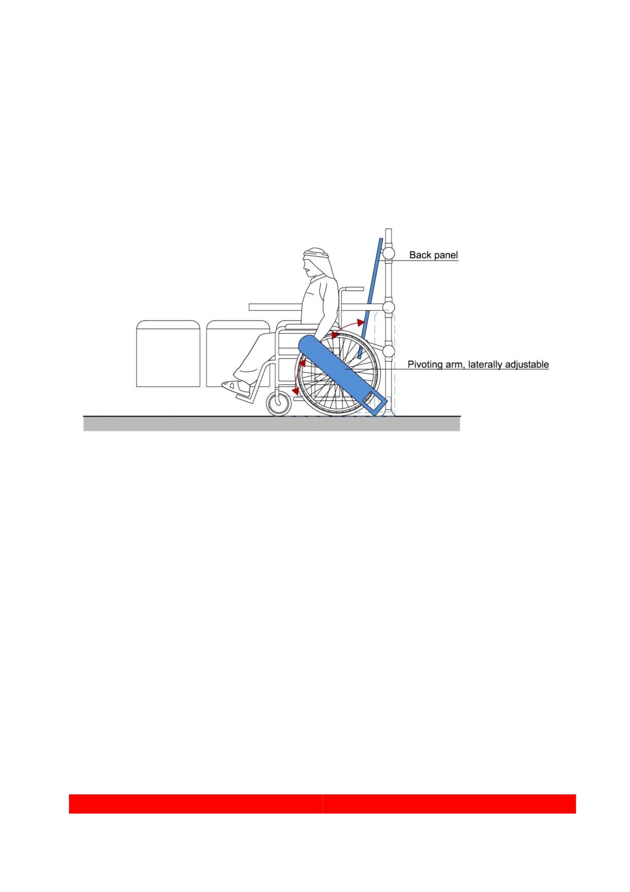
1. Each wheelchair space shall be fitted with a rear-facing system, where the
wheelchair and the occupant face the rear of the vehicle. The rear-facing system
shall be provided with a padded back panel with the following dimensions:
• Height from floor to bottom edge: 350-480 mm
• Height from floor to top edge: 1300 mm min
• Width: between 250 mm and 400 mm
• Back panel shall withstand a decelerating force of 3 g.
2. The rear-facing securement shall have a pivoting aisle arm, which is also laterally
adjustable to accommodate people using different wheelchair types and prevent
them from moving longitudinally and laterally.
3. The vehicle shall be fitted with a horizontal handrail along the longitudinal side of
750 mm - 1000 mm from the floor, not to exceed the wheelchair space by more than
90 mm, and have a diameter of 30 mm - 40 mm with a clear knuckle space of 35
mm between any part of the vehicle and the handrail.
175
4. The wheelchair space shall have a call button to alert the driver, mounted on the bus
wall or on the horizontal grab bar at a height of 750 mm - 1000 mm from the floor.
The call button shall be clearly labeled and provided in tactile format, high contrasted
characters and be operated by touch.
5. The driver shall be trained to operate the securement system and the ramp.
Figure 112. Rear-facing securement with pivoting aisle arm - securement technology for
low g transportation in buses and rail
9.4.3.
Stop announcements
For persons in seats that face the rear of the bus, a Next Stop text display shall be
provided to be visible from their position.
9.4.4.
Priority seating
1. At least one priority seat shall be located close to the driver and entrance door. The
seats shall be reserved for passengers who have mobility, sensory or cognitive
disabilities, and seniors. Hip-to-knee room shall be no less than 675 mm in front of
the seat in a forward-facing position.
2. Each priority seat and wheelchair space shall be equipped with stanchions,
handholds, or handrails.
3. Each bus shall post sign(s) to indicate that certain seats are designated priority
seats for seniors and persons with functional limitations. Other passengers shall
176
make such seats available to those who wish to use them. Priority seats shall not be
located in the area of the wheelchair space.
4. A sign following the criteria of Section D shall inform about seats priority.
9.4.5.
Family and gender seating
1. Appropriate separate and designated seating for family and gender separation shall
be provided according to local customs. Clear signage shall indicate the location(s).
2. Pregnant women, mothers with children, seniors and female passengers who have
mobility, sensory or cognitive disabilities shall have the option of being
accommodated separately in the section reserved for family seating.
9.4.6.
Seat surfaces
1. Sitting surfaces, especially those of aisle-facing seats, shall be covered by materials
with a coefficient of friction sufficient to prevent passengers from sliding back and
forth during sudden starts and stops.
2. The seat profile shall be ergonomically contoured. Bench seats shall be provided for
large/obese persons without armrests between the seats.
9.5. Illumination, lighting, signage
9.5.1.
Lighting
1. Adequate lighting shall be provided for those with reduced vision, and for the safety
and security of all passengers.
2. When the vehicle door is open, 30 lux of illumination as measured on the step tread
or ramp platform shall be provided.
3. All vehicle doorways shall have outside lights that illuminate when the door is open
and provide at least 10 lux of illumination on the street surface for a distance of 1000
mm perpendicular to the bottom step tread or ramp outer edge. These light(s) shall
be shielded to protect the eyes of entering and exiting passengers.
9.5.2.
Visual elements
1. Reflectance contrast of at least 30 points LRV shall be used for signage and for
station features such as railings, turnstiles, wide fare gates, tactile warnings at bus
177
entry gates, folding seats, and perch supports. Specific colors shall be selected for
persons who are colorblind and can only see red and green as gray.
2. Uniform signage shall be provided for everyone, including persons with cognitive
impairments, visitors, tourists, and others who may not be able to read text.
9.5.3.
Colour coding
The number of colors should be kept down to 5 and the number of datum per color
equal. The colors should be arranged so that information arranged adjacently is
always different colors.
Color shall be used consistently for the same functions.
9.6. Onboard passenger information
9.6.1.
Alternative formats
Alternative audio and text display and inductive loop systems for information shall be
used for next stop announcements, transfers and connections to address the
requirements of seniors, deaf/hard of hearing, blind/vision and persons with cognitive
impairments.
Noise level shall not exceed 70dB(A) to avoid hearing interference.
For foreigners who do not speak the local language(s), multi-language announcements,
and symbols/pictograms shall be used.
Advanced technologies shall be considered to interface between driver announcements
and personal communication devices (e.g. phones/tablets) via Bluetooth or similar
systems for real time audio and text display.
9.6.2.
Emergencies and evacuations
Clearly posted evacuation and emergency warnings and instruction, in large print, shall
be provided in the vehicle.
Safety announcements shall be made in visual and audio format in case of emergencies
and evacuations.
Staff training and drills shall be provided about emergency and evacuation situations to
assist persons with mobility and sensory impairments.
178
9.6.3.
Bus arrival systems
The number of the bus arriving and the route shall be shown in real time on monitors at
bus stations, shelters and stops.
The number of the bus arriving and the route should be available on Bluetooth on a
personal phone with audio.
9.7. Service animals and allergens
9.7.1.
Service animals
Space shall be provided for service animals out of the pedestrian path but appropriately
close to their owner.
9.7.2.
Food, smoking & allergens
No food or drink shall be allowed in the urban bus.
Smoking is forbidden in all buses.
Cleaning products should not leave a residual odor.
Allergy considerations shall be observed.
In the event of a passenger identifying his/her allergies to the driver, he should make an
announcement to the other passengers to observe the allergy condition. He should than
set up a buffer zone.
9.8. Group travel
9.8.1.
Group vehicles
A single level coach shall be equipped with the following features (Fig. 16):
Ramps at service doors.
Side facing flip seats on both sides of the low floor sections of the bus.
Four (4) rear-facing wheelchair securement systems, two (2) on each side.
179
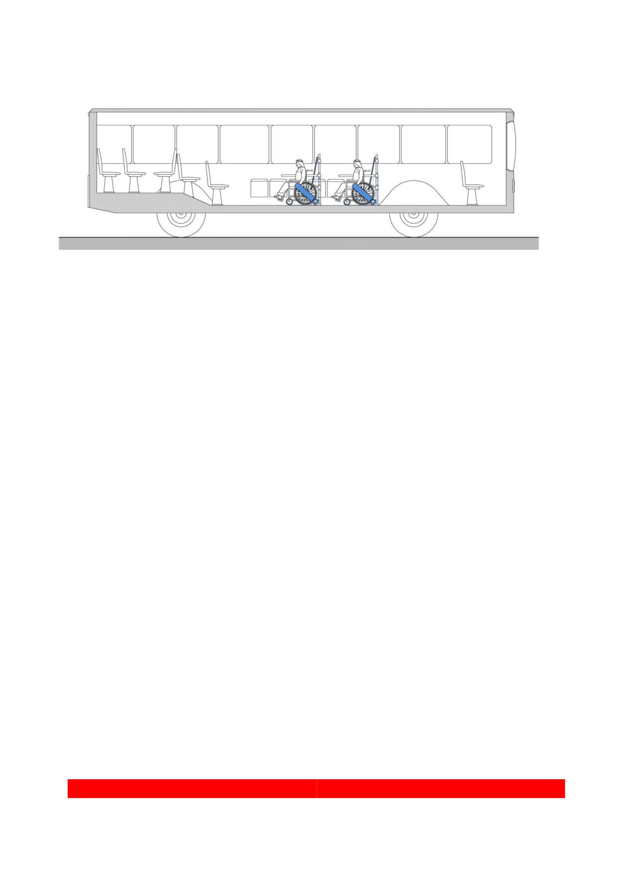
Figure 113. Bus layout for group travel with four wheelchair positions, two on each side
9.9. Vehicle infrastructure interfaces
9.10. Stops
As a minimum, stop locations shall have a level paved, slip-resistant surface with a
signpost indicating the vehicle route. The front edge of the paved surface shall have a
bright colored strip. If not leveled with the road, a curb cut shall provide access for
disabled and elderly persons. Stops shall include a bench for seating. A large print
schedule, route map, fares, and Help Line number shall be attached to the post. Stops
shall be located in an area with cover/shade to protect against sun and heat.
9.10.1. Shelter
Bus shelters shall consist of a minimum sheltered structure with a roof and protected
sides. The platform surface shall be flat, level, slip-resistant and solid.
A bench shall provide seating with provisions for obese persons and pregnant women
without armrests in between seats, but with armrests at both ends of the bench. A
space for a wheelchair/scooter shall be 865 mm x 1400 mm to enter, turn and exit.
The sidewalk shall have a minimum depth of 2700 mm from the curb for a
wheelchair/scooter to board a vehicle over a ramp.
180
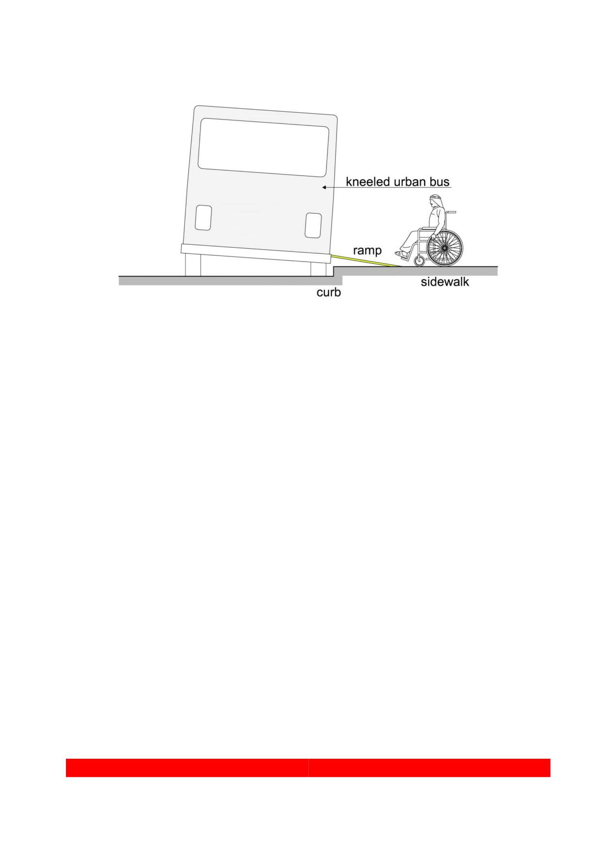
Figure 114. Ramp from curb to bus with landings
181
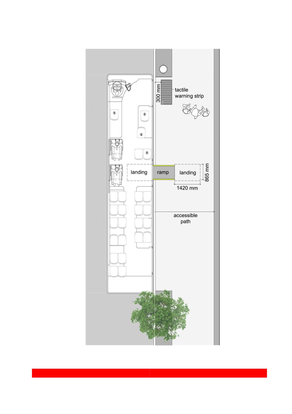
Figure 115. Bus interface with infrastructure
182
Along the front edge of the platform shall be a high contrast color-warning strip for
persons who are blind or have low vision.
A large print schedule and route map shall be shown.
Transparent sides/windows shall be provided for safety during day times, as well as for
safety at night with interior and exterior lighting.
A “Help Line” phone shall be available to provide information and help. The help line
phone shall be at a maximum height of 1100 mm, be color contrasted and should have
tactile and Braille controls. There should be an alternative means of communication for
people who are deaf in the form of a visual display.
183
10. Metro Trains
10.1. Considerations
Automatic door closings are the biggest issues for children, seniors, and parents with
strollers, persons with baggage and persons with mobility impairments, in particular at
rush hour with large crowds entering and exiting the cars.
In Dubai, due to social cultural consideration, there is a need to designate sections for
family and gender seating within the vehicle or in separate cars.
Next-stop announcements, a dynamic visual route display and announcements in audio
and text of the station number would improve information for visitors not familiar with the
local environments.
Consideration should be given to avoiding known allergens. Education, sensitization,
and training of both operators and passengers on their respective rights and
responsibilities will contribute to making the Dubai transport system a universally
accessible and socially responsible model.
Access to a Metro shall be universal and apply to the dimensions and maneuvering
characteristics of all persons using mobility aids, luggage, prams/ strollers, service
animals, persons with vision, hearing and cognitive and other disabilities.
10.2. Boarding and alighting
10.2.1. Gaps of train
There shall not be any significant gaps between the platform and the train to hinder
passengers using mobility devices from boarding and disembarking.
The low floor train car shall be level with the platform.
A horizontal gap between the train and the platform not to exceed 50 mm.
Vertical gap not to exceed 15 mm.
10.2.2. Doors
Doors leading into cars with designated seats or designated wheelchair space shall
have an obstacle free minimum clearance of 900 mm.
184
All doors shall be automatic. When a door is opening or closing there shall be an
acoustic and visual warning signal to alert/inform passengers.
When the car door is enabled for opening, a signal shall be given that is clearly visible
and audible to persons inside and outside the train. This acoustic alert signal shall
sound for a minimum of 5 seconds. This visual alert signal shall flicker during the same
period. When a door is automatically or remotely opened by the driver or member of the
train crew, the acoustic alert signal shall sound for a minimum 3 seconds from the
moment that the door starts to open. This visual alert signal shall flicker during the same
period.
When a door is automatically or remotely closed, or is about to operate, a signal shall
be given to persons inside and outside the train. The acoustic alert signal shall sound
for a minimum of 2 seconds before the door starts to close and shall be different in tone
to that used when the door is released. This visual alert signal shall flicker during the
same period. The signal shall continue while the door is closing.
The door, once opened, shall remain open for a period of not less than 5 seconds
before it closes.
Automatic doors shall incorporate devices that detect if any door is about to close on a
passenger. When a passenger is detected, the doors shall stop automatically and
remain open for a limited period of time. Sensors at two heights shall be provided to
avoid doors trapping persons using mobility devices or guide dogs.
Doors shall be contrast marked, at least LRV 30, to be easy to locate from the inside
and outside of the vehicle.
10.2.3. Designated seats
1. Number of designated seats
Not less than 10 percent of the fixed seats by train set or individual car and by class
shall be designated as priority seats for the use of persons with functional limitations.
These seats shall be designated by accessibility symbols.
2. Location
Designated seats shall be located close to an accessible door for boarding and
alighting.
185
3. Design:
Seats shall be at the height of 430 mm to 500 mm. The sitting area shall have a depth
of 400 mm to 450 mm and minimum width of 440 mm. The seats shall have backrests
and foldable armrests mounted on the aisle side.
There shall be an obstacle free head clearance of minimum 1860 mm above the floor
surface except on bi-level trains on which luggage racks are provided above the seats.
In such case, reduced headroom of 1520 mm is permitted for priority seats underneath
the luggage racks, provided that at least 50% of priority seats maintain headroom of
1860 mm.
There shall be an appropriate leg space in front of a seat. The minimum distance
between a backrest and the backrest at the seat in front shall be 680 mm and there
shall be an appropriate clear foot space under the seat in front.
There shall also be a clear space between the front edge of the seat cushion and the
vertical plane for the seat in front of a minimum of 230 mm.
Where facing priority seats are provided, the distance between the front edges of the
seat shall be a minimum of 600 mm.
Where facing priority seats are equipped with a table, there shall be a minimum clear
horizontal distance between the front edge of the seat cushion and the leading edge of
the table of at least 230 mm.
At least two designated seats shall have enough space to allow for accommodation of a
guide dog.
None of the designated seats shall be foldable.
Sitting surfaces, especially those of aisle-facing seats, shall be covered by materials
with a coefficient of friction sufficient to prevent passengers from sliding back and forth
during sudden starts and stops.
The seat profile shall be ergonomically contoured. Bench seats shall be provided for
large/obese persons without armrests between seats.
186
10.2.4. Wheelchair space
1. Location of wheelchair space
The designated wheelchair space shall be close to an accessible door in the low floor
area of the car.
To ensure stability, the wheelchair space shall always be positioned either facing
forward or with its back in the direction of travel.
Flip-up seats may be fitted in the wheelchair space longitudinally along the sidewall or
transversely at the opposite end from the designated wheelchair space or at the back
of the wheelchair space.
2. Design of wheelchair space
There shall be a designated floor space for wheelchairs with a minimum of 1400 mm
in length parallel to the side of the car. The minimum clear width of the space shall be
865 mm.
If there is a passenger seat facing the wheelchair space, the minimum distance shall
be not less than 300 mm between the designated space and the seat.
If there is a passenger seat with its back against the wheelchair space, or there is a
partition or a closed flip-up or foldable seat in front of a wheelchair space, the
minimum distance shall be not less than 200 mm between the designated space and
the seat.
There shall be an obstacle-free maneuvering space at a minimum of 1500 mm x 1500
mm to move from the entrance door to the designated space. The wheelchair space
may be part of the turning circle.
3. Wheelchair Securement
There is no requirement for securing a wheelchair onboard Metro cars according to
international best practices.
4. Alarm device/call button
The wheelchair space shall be fitted with an alarm device/call button to enable the
person in a wheelchair to call the operator/ staff for assistance in case of need.
187
The call button shall be placed within easy reach of the passenger in the wheelchair
and shall be operated by the palm of the hand or elbow.
Minimum dimension of the alarm device/call button shall be square (50 mm x 50 mm)
or round (diameter of 50 mm).
It shall be at a maximum height of 1100 mm.
Operation force for buttons shall be 2.5 N to 5.0 N. When the button is pushed, a
visible and audible signal shall be given as feedback upon activation.
10.2.5. Floor
1. Surface
Floor surfaces shall be firm, level, non-glare and slip resistant.
Inside the vehicle, the path to and position of external doorways shall clearly be marked
by contrasting floor patterns and color contrast, LRV 30.
2. Height difference
The floor surface shall be level for the entire set of train cars.
There shall not be any rise over 15 mm from the vestibule of a wheelchair accessible
exterior door to designated seats and wheelchair space except for a door threshold strip
not exceeding 15 mm in height and shall be chamfered.
10.2.6. Handrails and grab bars
1. Provision of handrails
Handrails and grab bars shall be provided at designated seats and by the wheelchair
space.
Handholds or vertical handrails or other items that can be used for personal stability,
while using the aisle, shall be provided on seat backs of all aisle-side seats unless the
seat touches the back of another seat facing in the opposite direction which is already
fitted with a handhold or touches a partition.
Handholds or other items that can be used for personal stability shall be positioned at a
height of between 800 mm and 1200 mm above the floor, shall not protrude into the
pathway and shall contrast with the seat.
188
In seating areas with fixed longitudinal seats, handrails shall be used for personal
stability. These handrails shall be at a maximum distance of 2000 mm apart, shall be
positioned at a height of between 800 mm and 1200 mm above the floor and shall color
contrast with the vehicle interior surroundings.
Any handrail fitted to a priority seat shall be movable to the extent required to permit
unrestricted access by a person to that seat or any other priority seat to which access
may be gained.
The handholds or other items shall not have sharp edges.
Handrails and grab bars should be color contrasted.
2. Design of handrails and grab bars
Handrails and grab bars shall have an elliptical profile of 50 mm width and 40 mm
depth, or thereabout, or have a circular profile of not less than 30-35 mm or not more
than 50 mm.
The handrail or grab bar shall be located to provide a space within a range of 30 mm to
60 mm from an adjacent wall or other obstructions.
The handrail or grab bar shall be supported vertically from below, with no less than 50
mm between the underside of the handrail and the top surface of the support.
There shall be a minimum of 600 mm clear space above the handrail or grab bar.
The surface of the handrail shall be slip resistant and contrasting at least LRV 30 to the
backg0round.
10.2.7. Signage
1. Doors
All accessible doors shall be clearly marked both inside and outside of a vehicle with the
international symbol for access, unless they all meet clear width requirements.
The symbol shall be placed on or beside the door at a height of 1100 mm to 1400 mm
from the ground surface (outside symbol) and from the floor surface of the train (inside
symbol).
189
2. Designated seats and wheelchair space
All designated seats shall be clearly marked for its purpose.
The wheelchair space shall be clearly marked with the international symbol of access.
10.2.8. Onboard travel information
1. Multi-media information
All information shall be provided at least in audio and visual formats, tactile or haptic as
appropriate. Information shall be given about the route number, station number,
destination, next stop and, if applicable, transfer connections. Automatic information
shall be turned on all the time. Travel information shall not be combined with
commercial ads or announcements.
2. Route and destinations signs
On each vehicle, the route and destination shall be clearly displayed in the front and
back and on both sides of the car.
3. Route map
There shall be a map showing the route of a vehicle. The map shall be posted on the
wall or on the wall close to the ceiling inside the vehicle, the map should be clear
enough and color contrasted with its surroundings. An additional route map can be
presented on the digital display. It is recommended that, if possible according to the
vehicle’s layout, the map could be tactile and with raised text or icons.
4. Audio announcement system
Audio information shall be given for emergency messages and travel information, e.g.
next and coming stops, transfer connections to other modes of transport, delays,
cancellations, etc.
Where provided, oral/audio information shall be consistent with essential visual
information being displayed.
Oral/audio information can be given in synthetic or by a human voice - recorded or in
real time.
All spoken information shall be easy to understand, clear and without echo.
190
An audio system shall be clearly audible and complemented with hearing enhancement
system. The information shall have a minimum RASTI level of 0,5 in all areas. The
audible message shall be adjusted to 15 dB(A) above surrounding noise level.
An induction loop should be installed.
An audio announcement shall be made for people waiting at the platform, e.g. to
announce route number and direction of the vehicle.
5. Electronic text displays
Screens and displays of moving texts providing onboard travel information shall be
visible from all seats. The minimum height from the floor surface shall be 2100 mm to
the bottom of the display.
Electronic displays shall be of as high resolution as possible. The front glass shall be
anti-reflective.
When displays are mounted at the minimum height of 2100 mm above floor surface, the
letters shall have a minimum height of 30 mm from a reading distance of 3000 mm.
It is preferable that the electronic display is tilted or is fitted with a glass that permits
reading of the text within an angle of 30º, which is the maximum angle for a comfortable
tilt of the head.
Letters and symbols shall be presented with light color on a dark backg0round at LRV 30.
White text on black, or dark blue is preferable. The use of red, and green shall be
avoided for persons with color blindness.
Screen fonts shall be specially designed for the display using them - letter type shall be
san serif.
When using scrolling text, it shall preferably be horizontal and not vertical. Latin text
shall scroll right to left and Arabic text left to right.
Audio information should have a self-adjusting volume depending on backg0round noise.
Sign Language interpretation for all audio information should be provided on a monitor.
Looping or scrolling text shall have a speed not to exceed 6 characters per second.
191
10.2.9. Service animals, food consumption, smoking and allergens
1. Service Animals
Space shall be provided for service animals out of the pedestrian path but appropriately
close to their owner.
2. Food Consumption
No food consumption shall be allowed in Metro cars.
3. Smoking is forbidden in all Metro cars
4. Cleaning products should not leave a residual odor
5. Allergy considerations shall be observed
10.2.10. Lighting & illumination
1. Lighting
There shall be sufficient light to safely board, alight and move inside a vehicle.
2. Illumination
The lighting shall be even and non-glare.
The luminance shall be 100 lux outside a vehicle at the entrance doors.
The luminance shall be 50 lux in the aisle from the accessible door/doors to the
designated seats and at the designated wheelchair space.
10.2.11. Infrastructure interface
The interface of the train with the platform shall comply with the following:
A straight-line platform for the whole length of the train.
Platform screen doors at full height.
A tactile and high contrast warning strip along the length of the platform edge facing the
train.
A horizontal gap between the train and the platform not to exceed 50 mm.
192
Vertical gap not to exceed 15 mm.
“Mind the Gap” sign on the platform at all door entrances and on train doors.
10.2.12. Emergency and evacuation
Emergency and evacuation information shall be provided in audio and visuals format in
real time.
Staff training and drills shall be provided for emergency and evacuation situations to
assist persons with mobility and sensory impairments.
193
11. Trams
11.1. Considerations
In Dubai, due to social cultural considerations, there is a need to designate sections for
family and gender seating within the vehicle.
Next-stop announcements, a dynamic visual route display and announcements in audio
and text of the station number would especially help visitors not familiar with the local
environments.
Education, sensitization, and training of both operators and passengers on their
respective rights and responsibilities will contribute to making the Dubai transport
system a universally accessible and socially responsible model.
Access to a tram shall be universal and apply to the dimensions and maneuvering
characteristics of all persons using mobility aids, luggage, prams/ strollers, service
animals, persons with vision, hearing and cognitive and other disabilities.
11.2. Boarding
11.2.1. Gaps of tram
There shall not be any significant gaps between the platform and the tramcars to hinder
passengers using mobility devices from boarding and disembarking. The low floor
tramcar shall be level with the platform.
The maximum gap between the doorsill of a car and the edge of a platform shall be:
•
75 mm measured horizontally
•
50 mm measured vertically
If a gap is wider than 75 mm, it shall be connected with a foldable bridge plate or a
ramp.
If a gap is higher than 50 mm, it shall be overcome with a ramp.
194
11.2.2. Doors
Doors leading into tramcars with designated seats or designated wheelchair space(s)
shall have an obstacle-free width of one single door of 900 mm. If a double door is
used, the obstacle free width of each door shall be 900 mm. The width may be reduced
by 100mm when measured between handholds.
All doors shall be automatic. When a door is opening or closing, there shall be an
acoustic and visual warning signal to alert/inform passengers.
When the car door is enabled for opening, a signal shall be given that is clearly visible
and audible to persons inside and outside the train. This acoustic alert signal shall
sound for a minimum of 5 seconds. This visual alert signal, e.g. a red light, shall flash
during the same period. When a door is automatically or remotely opened by the driver
or member of the train crew, the acoustic alert signal shall sound for a minimum 3
seconds from the moment that the door starts to open. This visual alert signal shall flash
during the same period.
When a door is automatically or remotely closed, or about to operate, a signal shall be
given to passengers inside and outside the train. The acoustic alert signal shall sound
for a minimum of 2 seconds before the door starts to close and shall be different in tone
to that used when the door is opened. This visual alert signal shall flash during the
same period. The signal shall continue while the door is closing.
The door, once opened, shall remain open for a period of not less than 5 seconds
before it closes.
Automatic doors shall incorporate devices that detect if any door is about to close on a
passenger. When a passenger is detected, the doors shall stop automatically and
remain open for a limited period of time. Sensors at two heights shall be provided to
avoid doors trapping persons using mobility devices or guide dogs.
Doors shall be color contrasted, at least LRV 30, in order to be easy to locate from the
inside and outside of the vehicle.
195
11.2.3. Boarding Equipment
1. Ramp
If there is a need for a ramp, it shall have the following features:
A ramp shall have a minimum width of 900 mm. It shall be provided with side guards of
50 mm high and color contrasted on both sides to prevent the passenger falling off the
ramp.
The gradient shall be maximum 8%.
A ramp shall have a payload of 350 kg.
Edges of a ramp shall be contrast marked with a 50 mm to 75 mm line along the entire
edges of the ramp and with contrast LRV 30 against the backg0round.
When a ramp is folding/sliding out or folding/sliding in there shall be acoustic and visual
warnings.
2. Buttons
There shall be a push-button to call the driver or crews’ attention when someone needs
to use the boarding equipment, to embark or disembark.
The stop request button shall be placed within reach of passengers in priority seats and
in the wheelchair space, and at a height above the floor surface with the central line of
the button at 700 mm to 1200 mm, preferable at 1100 mm, at the wheelchair space.
If push-buttons or other remote control devices are provided for the operation of doors,
these shall be placed at the inside and at the outside of the vehicle close to the
accessible door/doors or at the door, at a height with the central line of the button at 900
mm to 1200 mm, preferable at 1100 mm, above the ground surface (Fig. 1).
All push buttons shall be tactile and contrast marked LRV 30, and capable of being
operated with the palm of the hand or elbow.
The minimum dimension of a push button shall be square (50 mm x 50 mm) or round
(diameter 50 mm).
The operation force for buttons shall be 2.5 N to 5.0 N. When the button is pushed,
there shall be a visible and audible signal as feedback.
196
In the seat-free low floor area of the tramcar the central line of the button shall be at a
height of 900 mm to 1200 mm, preferably 1100 mm above the floor surface.
11.2.4. Designated seats
1. Number of designated seats
There shall be at least 4 seats designated for persons with functional limitations in each
tramcar. The seats shall be clearly marked. The space for the wheelchair shall be
marked with the international symbol of access.
2. Location
Designated seats shall be located close to an accessible door for boarding.
3. Design
Designated seats shall be at the height of 430 mm to 500 mm. The sitting area shall
have a depth of 400 mm to 450 mm and minimum width of 440 mm. The seats shall
have backrests and foldable armrests mounted on the aisle side.
There shall be an obstacle free head clearance of a minimum of 1300 mm above the
seat surface of a seat.
There shall be an appropriate leg space in front of a seat. The minimum distance
between a backrest and the backrest at the seat in front shall be 680 mm and there
shall be a clear foot space of 280 mm from front edge of seat under the seat in front.
At least one of the designated seats shall have an appropriate space to accommodate a
guide dog. Guide dogs come in various sizes and can range in length from 700 mm to
100 cm and in height from 450 mm to 600 mm.
None of the designated seats shall be foldable.
Sitting surfaces, especially those of aisle-facing seats, shall be covered by materials
with a coefficient of friction sufficient to prevent passengers from sliding back and forth
during sudden starts and stops.
The seat profile shall be ergonomically contoured. Bench seats shall be provided for
large/obese persons without armrests between seats.
197
11.2.5. Wheelchair space
There shall be at least one wheelchair space for a person using a wheelchair in each
car. The space shall be clearly marked with the international symbol of access.
1. Location of wheelchair space
The designated wheelchair space shall be close to an accessible door in the low floor
area of the car.
To ensure stability, the wheelchair space shall always be positioned either facing
forward or with its back in the direction of travel.
Passengers using wheelchairs shall be asked to apply the brakes of their device during
travel.
Flip-up seats may be fitted in the wheelchair space longitudinally along the sidewall or
transversely at the opposite end from the designated wheelchair space or at the back of
the wheelchair space.
2. Design of wheelchair space
There shall be a designated floor space for wheelchairs with a minimum of 1400 mm in
length parallel to the side of the car. The minimum width of the space shall be 865 mm.
There shall be an obstacle-free maneuvering space at a minimum of 1500 mm x 1500
mm to move from the entrance door to the designated space. The wheelchair space
may be part of the turning circle.
3. Wheelchair securement
There is no requirement for securing a wheelchair onboard tramcars according to
international best practices. If a rear-facing wheelchair position is used, the person in a
wheelchair shall back against the support panel.
11.2.6. Floor
1. Surface
Floor surfaces shall be firm, level, non-glare and slip resistant.
Inside the vehicle, the path to and position of external doorways shall be clearly marked
by contrasting floor patterns and color contrast of LRV 30.
198
2. Height difference
The floor surface shall be level for the entire set of tramcars.
There shall not be any internal step from the vestibule of a wheelchair accessible
exterior door to designated seats and the wheelchair space.
11.2.7. Handrails and grab bars
1. Provision of handrails
Handrails and grab bars shall be provided at designated seats and in the wheelchair
space.
Handholds or vertical handrails or other items that can be used for personal stability,
while using the aisle, shall be provided on seat backs of all aisle-side seats unless the
seat touches the back of another seat facing in the opposite direction which is already
fitted with a handhold or touches a partition.
Handholds or other items that can be used for personal stability shall be positioned at a
height of between 800 mm and 1200 mm above the floor. It shall not protrude into the
pathway and shall contrast with the seat.
In seating areas with fixed longitudinal seats, handrails shall be used for personal
stability. These handrails shall be at a maximum distance of 2000 mm apart, shall be
positioned at a height of between 800 mm and 1200 mm above the floor and shall
contrast with the vehicle interior surroundings.
Any handrail fitted to a priority seat shall be movable to the extent required to permit
unrestricted access by a person to that seat or any other priority seat to which access
may be gained.
The handholds or other items shall not have sharp edges.
Handrails and grab bars should be color contrasted.
199