Cat Lift Trucks. For use with K21/K25 and S4S Engine Service Manuals (2007) - page 3
NG SYSTEM
Structure and Function
1o
1
Steering System
10 -
1
Steering Gear
10 -
2
Steering Column
10 -
3
Disassembly and Reassembly
-
Disassembly and Reassembly of Piping
10 -
4
Removal and Installation of Steering Wheel and Steering Valve
10 -
5
1. Steering wheel
10 -
5
2. Steering valve
10 -
7
3. Tilt lock lever
10
7
Steering
Valve
1
-
8
Disassembly
10 -
8
Reassembly
10. 10
Troubleshooting
. 14
Data
. 15
STEERING SYSTEM
Structure and Function
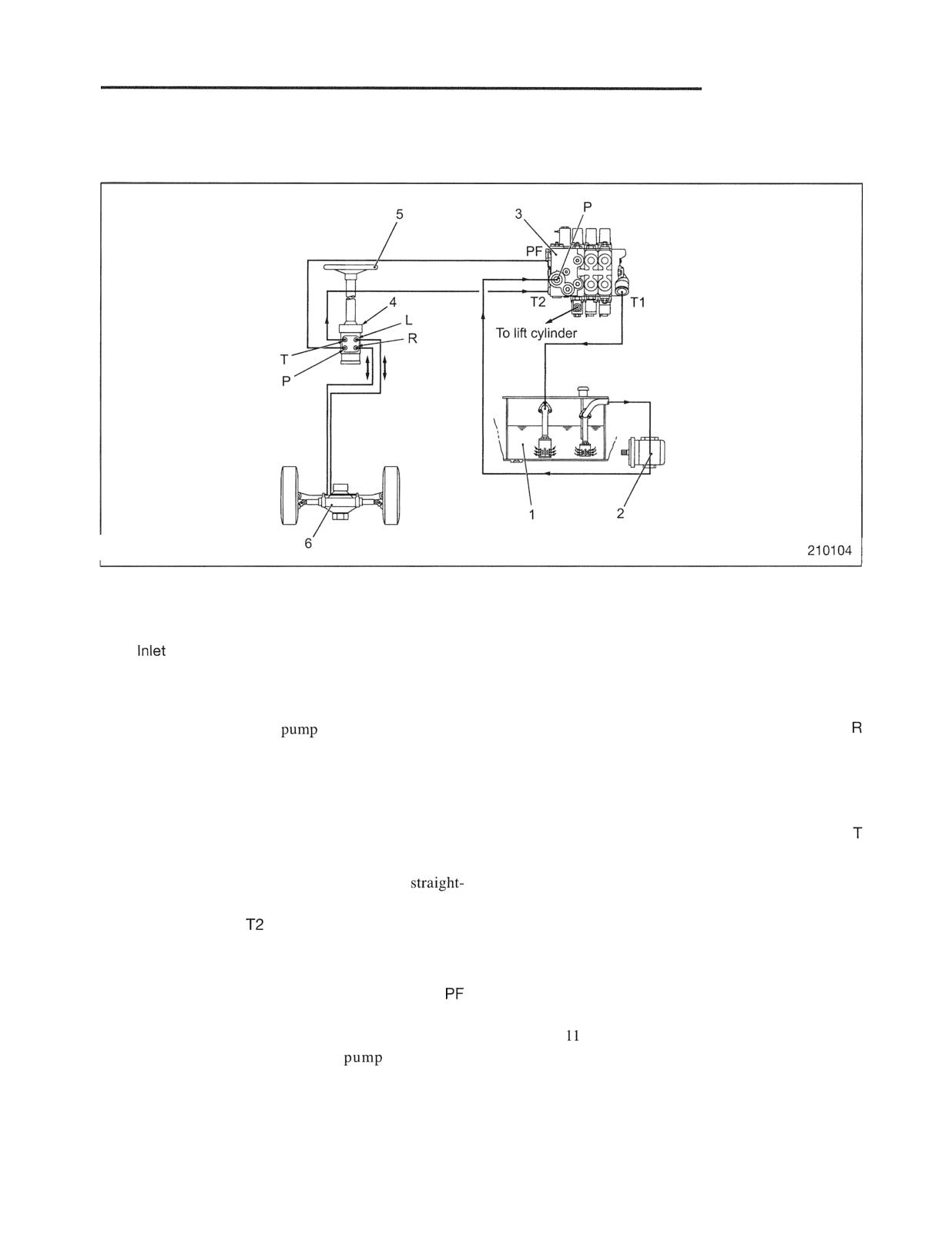
Steering System
Main Components
1 Hydraulic tank
4 Steering valve
2 Hydraulic pump (Gear pump)
5 Steering wheel
3
section of hydraulic control valve
6 Steering cylinder
(Including flow priority valve)
The steering system of this lift truck is full hydraulic.
The oil delivered from the Gerotor is directed to the left
The oil drawn by hydraulic
2 from hydraulic tank
or right chamber of steering cylinder through the L or
1 enters the inlet section of the hydraulic control valve
port, applying a pressure to the cylinder rod.
3 through the P port. There is built-in flow priority
Simultaneously, the spool-and-sleeve valve in the
valve in the inlet section. The function of the flow
steering valve 4 opens the return oil passage from the
priority valve is to deliver pressure oil preferentially to
chamber of the steering cylinder to the hydraulic tank
steering valve 4. From the PF port, the oil flows to the
1. (The return oil goes through the steering valve's
P port of the steering valve.
port and then the hydraulic control valve 3 to the
hydraulic tank 1 .)
When the steering wheel is not turned (in the
ahead position), the oil flows through the steering
Two actions of the steering cylinder piston, each of
valve's T port to the
port in the hydraulic control
which supplies and returns pressure oil, respectively,
valve's inlet section and then returns to hydraulic tank
extend the cylinder rod to the right or left. These
1.
actions turn the knuckle via the tie rod, steering rear
wheels.
When the steering wheel is turned, the oil from the
port enters the "Gerotor" passing through the P port
For the priority valve and the steering cylinder, refer to
and spool-and-sleeve valve in the steering valve 4.
"GROUP
HYDRAULIC SYSTEM" and "GROUP 8
(The Gerotor is a small trochoid
capable of
REAR AXLE," respectively.
delivering oil at a rate proportional to the number of
turns in which the steering wheel is turned.)
SYSTEM
Steering Gear
a,
c: Metering pump inlets
f: Metering pump outlets
c
8
9
2
1
7
1
2
5
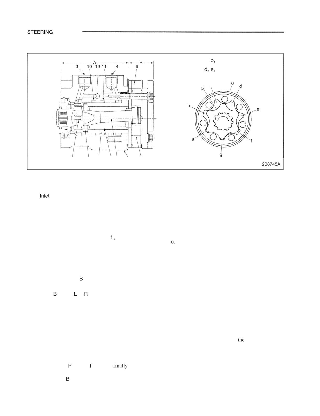
1 Spool
7 Drive shaft
A: Control section
2 Sleeve
8 Centering spring
B: Metering section
3 Outlet port (port T)
9 Pin
4
port (port P)
10 Left turn port (port L)
5 Rotor
11 Right turn port (port R)
6 Rotor ring
12 Housing
The steering valve consists of two sections: control
When the operator turns the steering wheel clockwise,
section A and metering section B.
the passage in the steering valve opens, allowing
pressure oil to flow through inlet port 4 into areas a, b,
Control section A includes spool
sleeve 2, and
and
housing 1 2 , constituting a rotary type directional
control valve. Spool 1 is spline-coupled to the steering
As rotor 5 turns together with the steering wheel, the oil
shaft. When spool 1 is turned, sleeve 2 rotates, opening
in areas d , e, and f is forced into the steering cylinder
the following passages to form a hydraulic circuit:
through right turn port 1 1 . When the steering wheel is
turned counterclockwise, oil flows in the direction
(1) A passage that allows oil to flow from inlet port 4
reverse to the above, entering the steering cylinder
to metering section
through left turn port 1 0.
(2) A passage that allows oil to flow from metering
Since the pressure oil from port 4 applies rotating force
section to port or
operator's effort on the steering wheel is
to rotor 5,
(3) A passage that allows the return oil from the
reduced.
steering cylinder to port T
Check valve 1 3 is normally pushed to the left direction
Metering section B is a trochoid-gear type, small
by pressure oil in the inlet port, blocking the bypass
hydraulic pump called "Gerotor" consisting of rotor
passage. When oil supply from the PF port of the
ring 6 and rotor 5.Spool 1 and rotor 5 are connected to
hydraulic valve stops for any reason, the bypass
each other with drive shaft 7. The rotor, therefore,
passage opens, allowing oil from
hydraulic tank to
turns in the same direction and at the same speed as the
flow to the metering section B. When the operator
steering wheel.
turns the steering wheel, the metering section acts as a
When the operator does not turn the steering wheel, the
complete manually-operated pump, causing oil to flow
oil flows from the port to port and
returns to
to the steering cylinder.
the hydraulic tank. The oil does not flow to the
metering section as it is blocked by the spool 1 and
sleeve 2.
10-2
STEERING SYSTEM
Steering Column
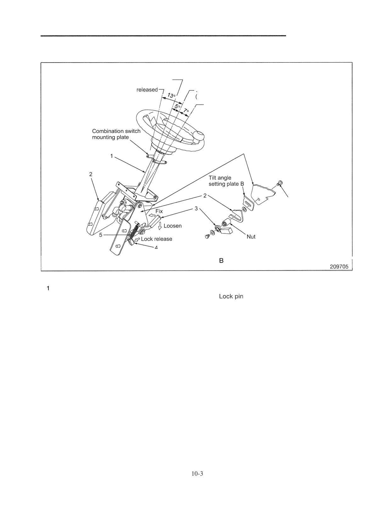
Column position when steering column
is tilted fully forward
Column position when lock is
Column neutral tilt position
inclination of 30 degrees to vertical line)
Column position when steering column is
tilted fully rearward
Steering column
mounting plate A
Bolt
When the tilt lever 3 is turned counterclockwise,
the plates A and are fixed between the bolt and
Main components
Steering column
4 Column lock lever
2 Bracket (secured to truck body)
5
3 Tilt lock lever
The steering column is tilt adjustable in the range of 5
degrees forward and 7 degrees rearward as shown in the
illustration.
For adjustment, lock the column lock lever 4 and then,
loosen the tilt lock lever 3 by turning it clockwise. Then,
tilt the steering column 1 to an adequate angle and turn the
tilt lock lever counterclockwise (pulling up) to lock.
The role of the column lock lever is to tilt the entire column
forward by a large amount for the convenience of getting
on and off, and of maintenance work. Push down the lock
lever to disengage the lock lever 4 from the lock pin 6 and
to tilt the steering column forward.
STEERING SYSTEM
Disassembly and Reassembly
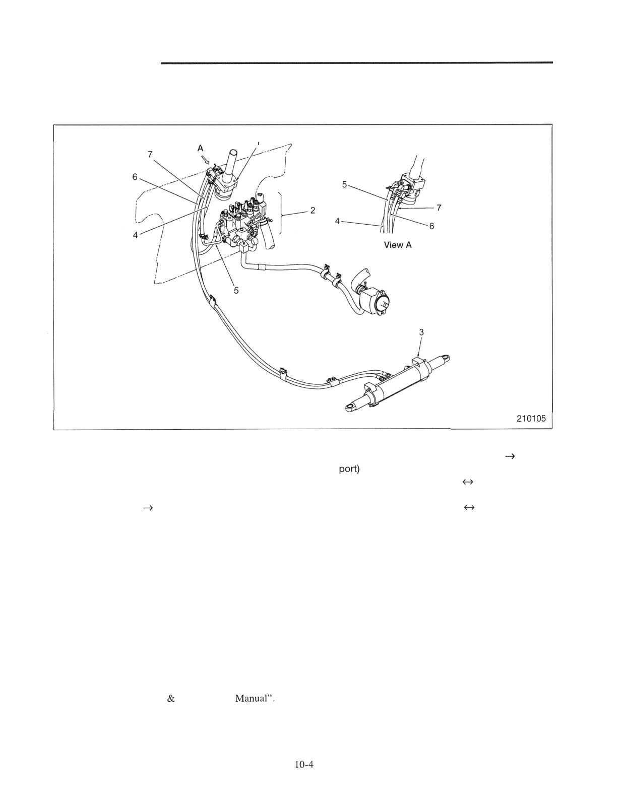
Disassembly and Reassembly of Piping
Main parts or devices
1 Steering valve
5 Hose and pipe (steering valve T port T2
2 Hydraulic control valve (The illustration shows
MC valve.)
6 Hose (steering valve L port
steering
3 Steering cylinder
cylinder)
4 Hose (PF port steering valve P port)
7 Hose (steering valve R port
steering
cylinder)
Suggestions for disassembly and reassembly
(1) The most important point in maintenance of the
(4) When removing or installing hoses, use a double
hydraulic system is to perform work in a clean
spanner as needed to prevent excessive force from
place and never allow abrasive foreign substance to
being applied to the matching fittings.
enter the system.
(5) Bleed air after reassembly. Air bleeding method is
(2) O-rings must be replaced, once disturbed.
as follows.
(3) Hoses (especially high-pressure section) of the
(a) Raise the rear tires by placing jack stands under
steering system are safety related parts. These
the truck body.
specially designed parts need to be replaced at
(b) While changing the engine revolution by
specific periods, regardless of the presence or
depressing the accelerator pedal, turn the
absence of damage. For replacement interval,
steering wheel lock-to-lock and relieve
follow the "Operation Maintenance
pressure to bleed air.
STEERING SYSTEM
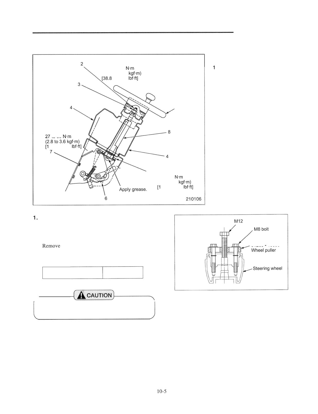
Removal and installation of Steering Wheel and Steering Valve
Disassembly sequence
Tightening torque:
52.6 to 65.3
Steering wheel
(5.36 to 6.48
2 Nut
to 46.8
3 Spring washer
4 Cover
5 Steering valve mounting bolt
6 Steering valve
1
7 Steering column assembly
mounting bolt
8 Steering column assembly
Tightening torque:
to 35
9.9 to 25.8
5 Tightening torque:
21 to 29
(2.1 to 3.0
5.5 to 21.4
Steering wheel
bolt
Removal
(1 ) Remove the horn button.
(2)
the steering wheel nut 2 and then, remove the
91268
10600
steering wheel 1 using a wheel puller.
Special tool needed
Wheel puller
91268 - 10600
209708
Wheel puller setting
When removing the steering wheel, do not tap
the top end of the steering shaft.
STEERING SYSTEM
Steering wheel
Horn switch contact
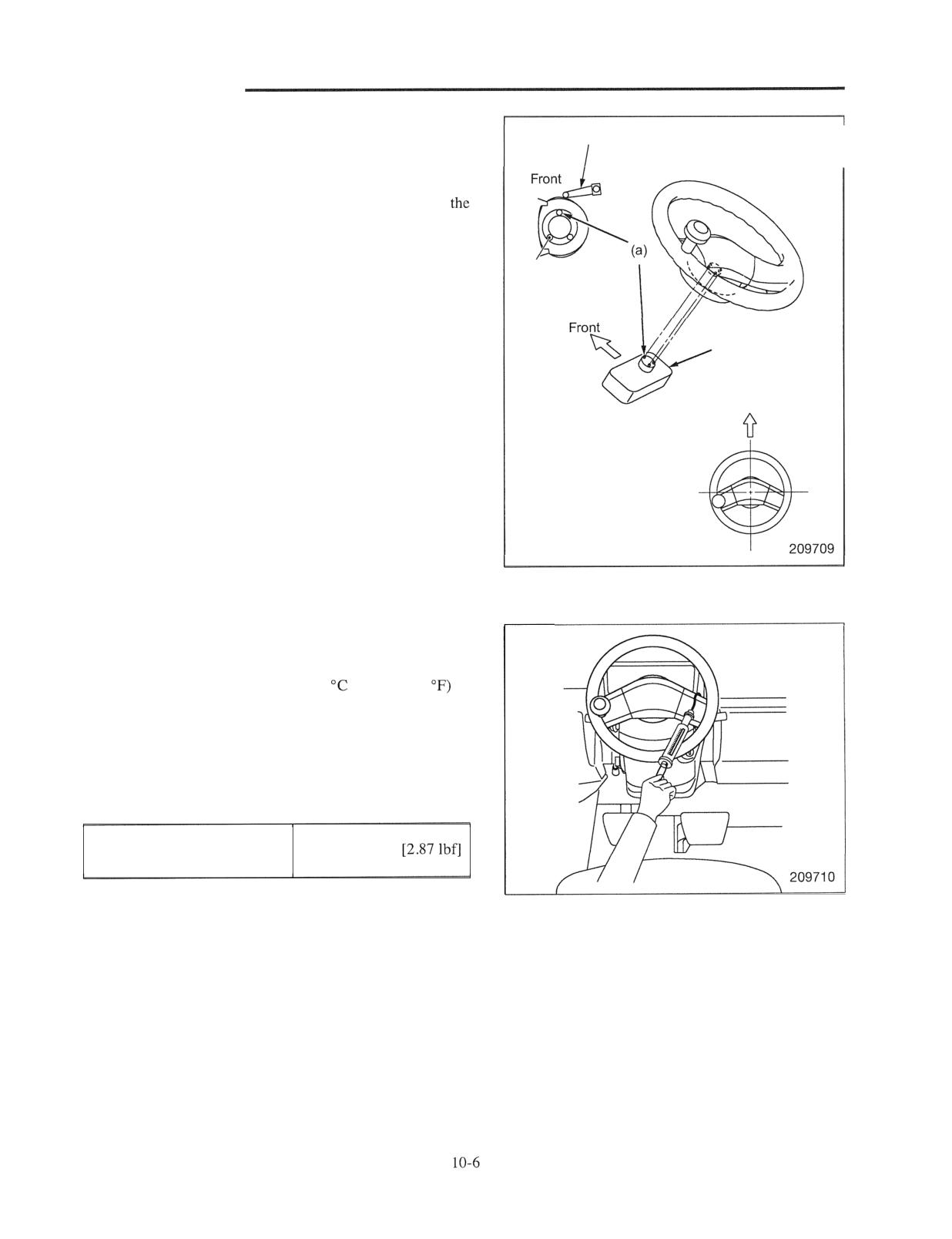
Installation
Install in the following sequence.
(1) Place the projection (a) on the steering sensor of
combination switch at the front as shown in the
illustration.
/
(2) Apply a light coating of grease to a sliding area of the
Projections form an
horn contact under the steering wheel boss.
isosceles triangle.
(3) Reassemble the steering wheel in a straight-ahead
position. (The projections of the combination switch fit
Combination switch
into the pits on the steering wheel.) Completely fit the
projections into the pits by turning the steering wheel
Forward
in the right and left directions several times.
(4) Before tightening the steering wheel nut, check that
automatic return of the combination switch functions.
(5) If automatic return does not function, repeat the
sequence (3) and (4) above.
(6) Tighten the steering wheel nut to the specified torque.
inspection after lnstallation
Steering effort
(1) Pull the hand brake lever.
(2) Run the engine to warm the hydraulic oil to an
operation temperature of 40 to 60
(104 to 140
(3) Attach a spring scale to the rim (or a spoke) of the
steering wheel, and measure the steering effort required
to turn the steering wheel clockwise or
counterclockwise from the straight-ahead position.
Steering effort
13 N (1.3 kgf)
(tangential force)
STEERING SYSTEM
2. Steering valve
Removal
Remove the cover 4 around the steering column.
Face the elbow right
downward to install.
(2) Disconnect four hoses connected to the steering valve.
Tightening torque of
(3) Remove the bolt 5 and then,
the steering valve
34 to 39
to
6.
to 28.8
Installation
Follow the sequence of disassembly in reverse, paying
attention to the following points.
(1) Apply grease to the serration area on the lower part of
the steering shaft.
(2) Tighten the mounting bolt to the specified torque.
(3) Be careful about the orientation when installing the
elbow on the steering valve. Tighten it to the specified
torque.
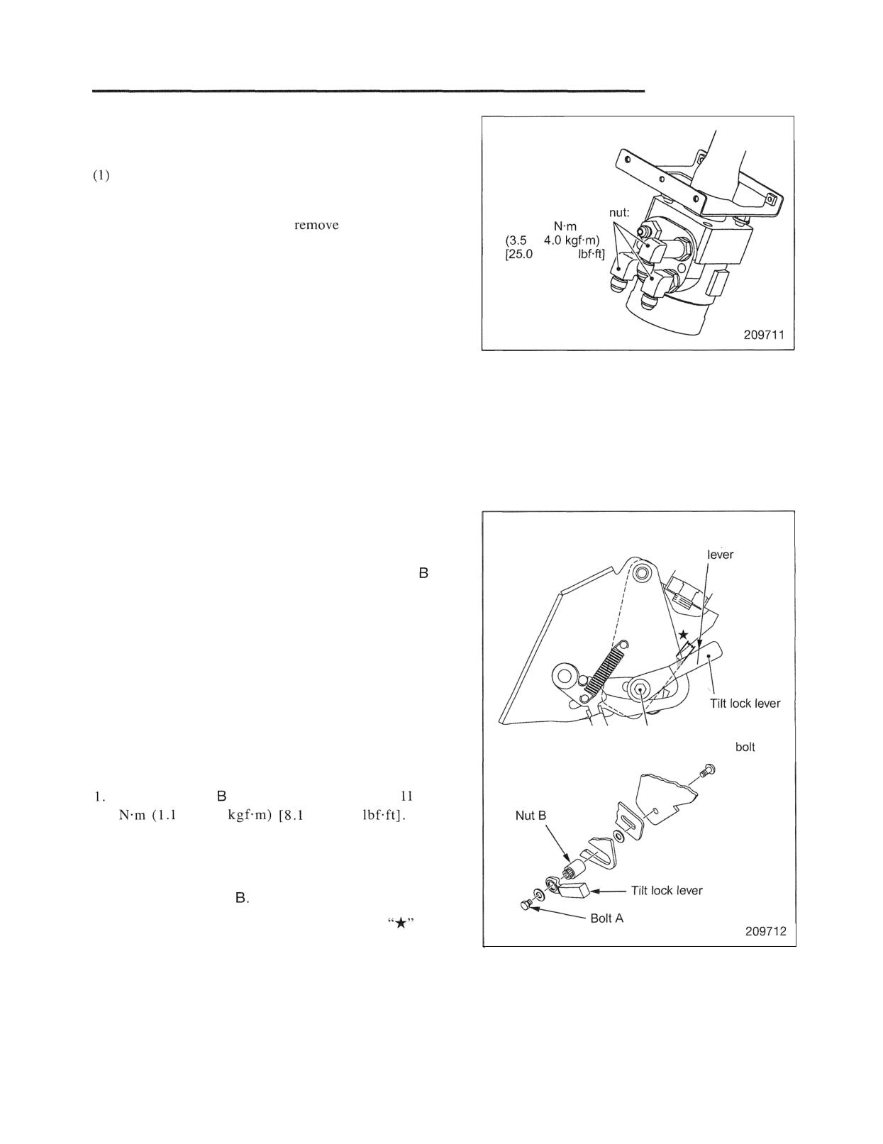
3. Tilt lock lever
Top face of
Disassembly
1. Put match marks on the tilt lock lever and the nut for
convenience of reassembly.
2. Remove the bolt A and then, remove the tilt lock cover.
Reassembly
When match marks put at the time of disassembly
disappear or when the lever is replaced with a new one,
install the lever in the following sequence. (The illustration
Lever mounting
on the right shows the layout of related parts when the tilt
position is neutral and the column lock lever is locked.)
Tighten the nut to the tightening torque of
to 15
to 1.5
to 11.1
(This
represents a lever-locked condition.)
2. Select the optimal position for the tilt lock lever in a
locked condition and fit the tilt lock lever into the
serration of the nut
The optimal position is in an area where the
notch
on the bracket and the top face of the lever cross each
other.
3. Tighten the bolt A.
4. Loosen the tilt lock lever and check that the bracket
slides in the entire tilting area without interfering with
other parts.
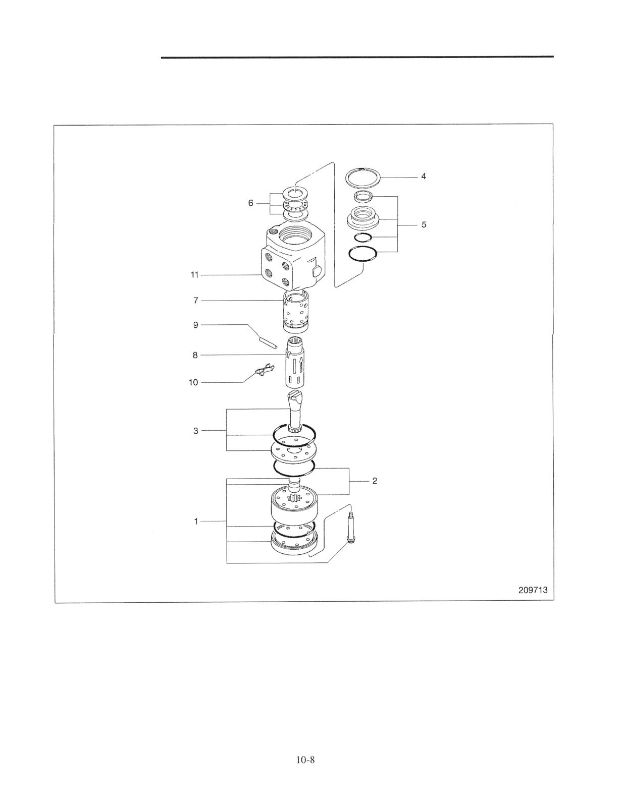
STEERING SYSTEM
Steering Valve
Disassembly
Sequence
1 End cap, Bolts, O-ring, Spacers
7 Control sleeve
2 "Gerotor" set, O-ring
8 Control spool
3 Drive shaft, Spacer plate, O-ring
9 Pin
4 Retaining ring
10 Centering springs
5 Seal gland bushing, O-ring, Oil seal, Dust seal
11 Long housing
6 Thrust needle, Race bearing
STEERING SYSTEM
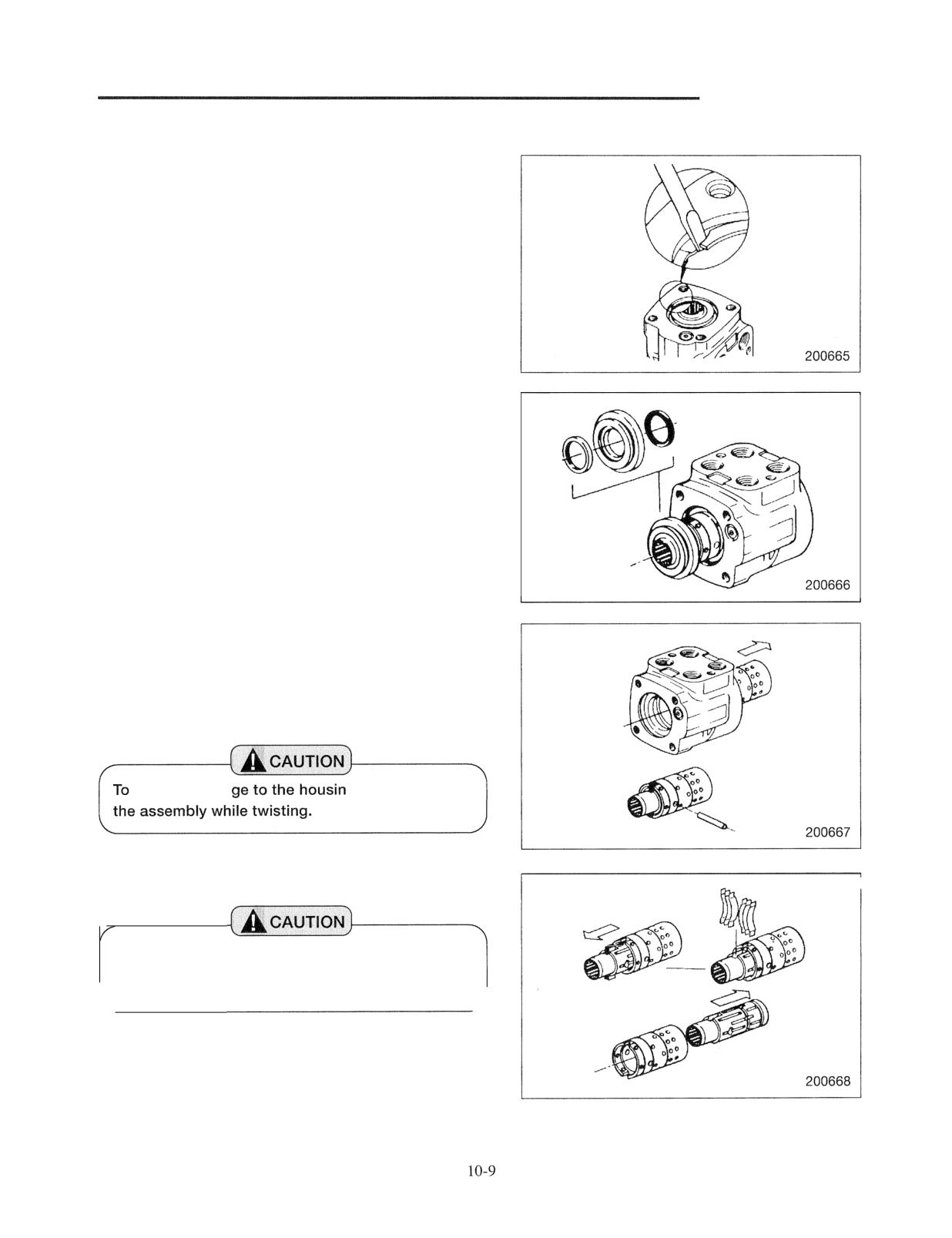
Suggestions for Disassembly
(1) Retaining ring removal
Remove the ring from the housing by prying its end out of
the groove. Do not damage the machined surface.
(2) Seal gland bushing removal
Position the control spool and control sleeve assembly so
that the pin is even with the center of the assembly.
Remove the gland bushing.
(3) Control spool and sleeve removal
Remove the control spool and sleeve assembly from the
housing by pulling it toward the end of the housing
opposite to the flange. Remove the pin from the
assembly.
prevent dama
g, slowly pull out
(4) Control spool and sleeve disassembly
Before removing the spool from the sleeve, put a
mark across the spool and sleeve so that the
spool can be installed in the same position.
Pull the control spool from the sleeve enough to permit
removal of the centering springs. Remove the centering
springs. Remove the spool from the sleeve by pulling it
toward the rear end of the sleeve while turning slowly.
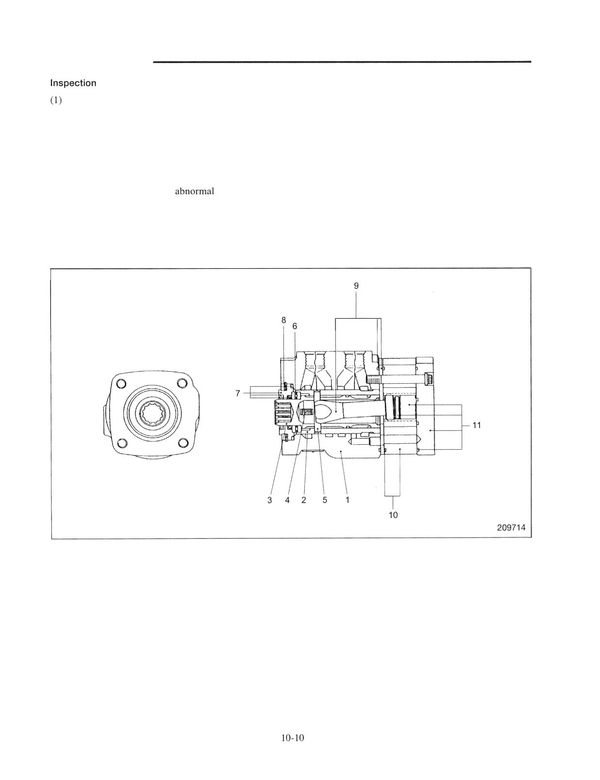
STEERING SYSTEM
after disassembly
Check sliding areas between the sleeve and the housing
and between the sleeve and the spool.
(a) Check for sliding movement in sub-assembly
condition.
(b) If any defective movement is found, check sliding
surfaces.
If any defect such as
wear, scratch, burr
or rust is found, replace the entire unit with a new
one.
Reassembly
Sequence
1 Long housing
7 Seal gland bushing, Oil seal, Dust seal, O-ring
2 Control sleeve
8 Retaining ring
3 Control spool
9 Drive shaft, Spacer plate, O-ring
4 Centering springs
10 "Gerotor" set, O-ring
5 Pin
11 End cap, O-ring, Spacer, Bolts
6 Thrust needle, Race bearings
SYSTEM
Perform the
(1) For damaged parts, prepare new parts for
(2) Clean all
parts, blow off foreign
substances with compressed air and dry them.
(3) Prepare new
for an O-ring seal and lip
Reassemble each part while applying a light
coating of oil to them.
(2) Apply grease to O-rings.
(3) Do not wear
gloves when reassembling.
Lint may enter the valve.
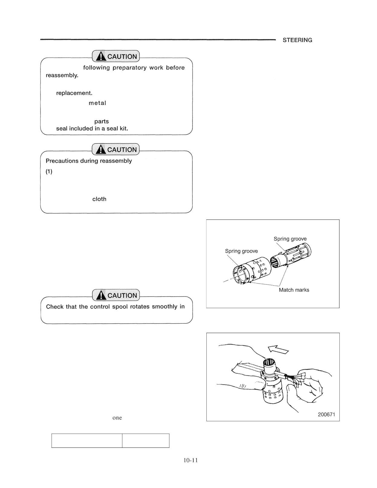
Suggestions for Reassembly
(1) Reassembly of control spool and sleeve
Check the direction in which the spring groove of the
sleeve is aligned with that of the spool and then, slide the
spool into the sleeve while twisting the spool.
If there are any match marks put at the time of disassembly
or marks put by a manufacturer, check such marks.
200670
the control sleeve.
(2) Installation of centering springs
Align the spring grooves of the spool-and-sleeve and stand
the spool-and-sleeve on a flat bench. Use the spring
inserting tool to install springs. Place each set of three
springs back to back and pinch six springs in the tool with
notches on both sides facing downward. See the
illustration on the right.
As shown in the illustration, push one end of the springs
with fingers and push the springs into the spool-and-sleeve
groove. In case there is no inserting tool, assemble the
springs by inserting them
by one and right and left
alternately.
Spring inserting tool
97157 - 00100
SYSTEM
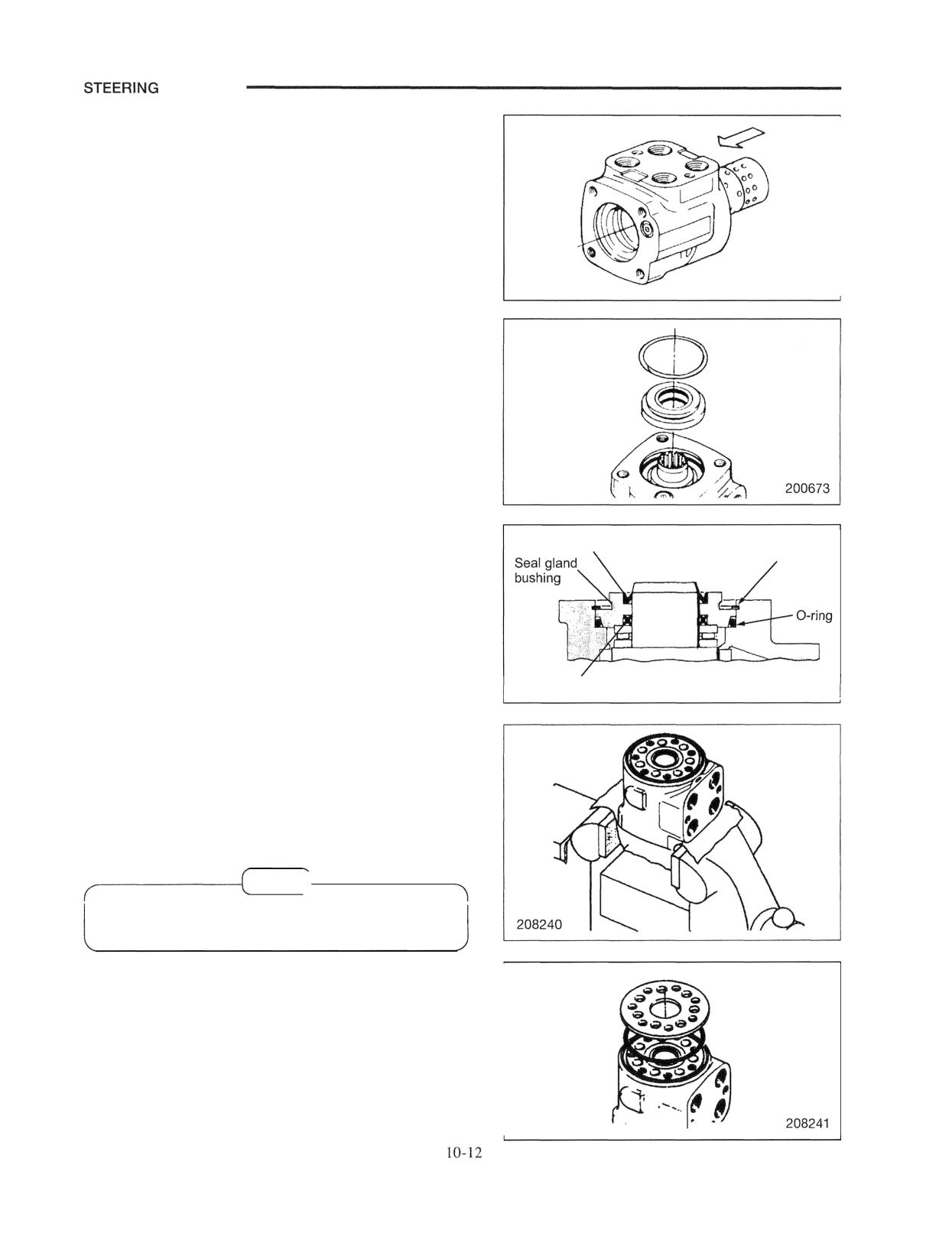
(3) Insertion of the control spool-and-sleeve assembly into
the housing
Insert the pin into the hole of the control spool-and-sleeve
assembly and align both ends of the pin with the outside
diameter of the sleeve. Insert the spool-and-sleevc
assembly into the housing from the rear (in the direction as
shown in the illustration).
Insert the spool-and-sleeve assembly while slowly twisting
it with the pin kept at a horizontal position. Insert the
spool-and-sleeve assembly until its rear edge face becomes
flush with the edge face of the housing. Do not insert any
further.
(4) Installation of thrust bearing
(5) Installation of seal gland bushing and seals
(a) Install the dust seal on the seal gland bushing to
place the flat side facing the bushing. Then install
the oil seal in the bushing.
(b) After installing the O-ring, fit the seal gland
bushing into the spool while turning the seal gland
Dust seal
Retaining ring
bushing. Drive the bushing into the specified
position by a plastic hammer. Check that the
bushing contacts the top face of the thrust bearing
race evenly.
Securely fit the retaining ring into the housing
groove.
Oil seal
209715
(6) Reassembling the spacer plate
(a) Clamp the housing in a vise equipped with soft
jaws or wrap the housing in a soft rag before
clamping the housing in the vise. Clamp lightly
over the flats of the flange. Do not over tighten the
vise jaws.
NOTE)
Check that the spool and sleeve are flush with or
slightly below the surface of the housing.
(b) Install the O-ring in the housing. Place the spacer
plate on the housing and align the bolt holes with
the tapped holes in the housing.
STEERING SYSTEM
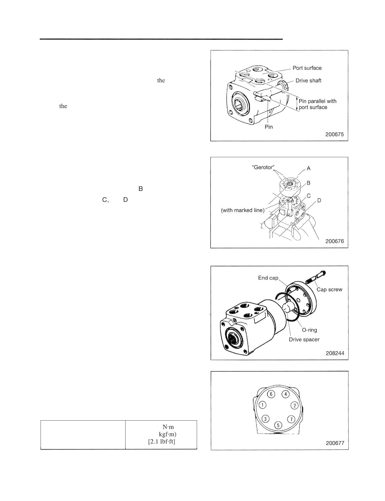
(7) Reassembling the drive shaft
Turn the control spool-and-sleeve assembly to make the
port surface of the housing parallel with the pin. Insert the
drive shaft to engage the pin in the yoke of
drive shaft.
To insure positioning in the following work process, draw a
line such as line B in the illustration right below on the end
face of
drive shaft spline with a felt-tip pen.
(8) Reassembling the gerotor set
Root of
Face the O-ring side of the rotor set toward the spacer plate
set star
side and fit the rotor set into the drive shaft by aligning the
Spacer plate,
root (line A) of the rotor set with line of the drive shaft.
Check that lines A, B,
and are in parallel with each
Drive shaft
other.
Align bolt holes of the "Gerotor" set with the drive shaft
and star kept engaged.
This procedure is important in determining the valve timing
of this unit.
(9) Reassembling the end cap
Install the drive spacer in the gerotor set. Install the O-ring
in the end cap. Install the end cap in the gerotor set and
align the holes.
Apply oil to bolt threads and tighten bolts evenly in the
sequence as shown in the illustration on the right. The
tightening torque is shown in the table below.
Install the steering shaft in the spool and check that the
spool turns smoothly.
28.4
Tightening torque of end cap
(2.9
mounting bolt
STEERING SYSTEM
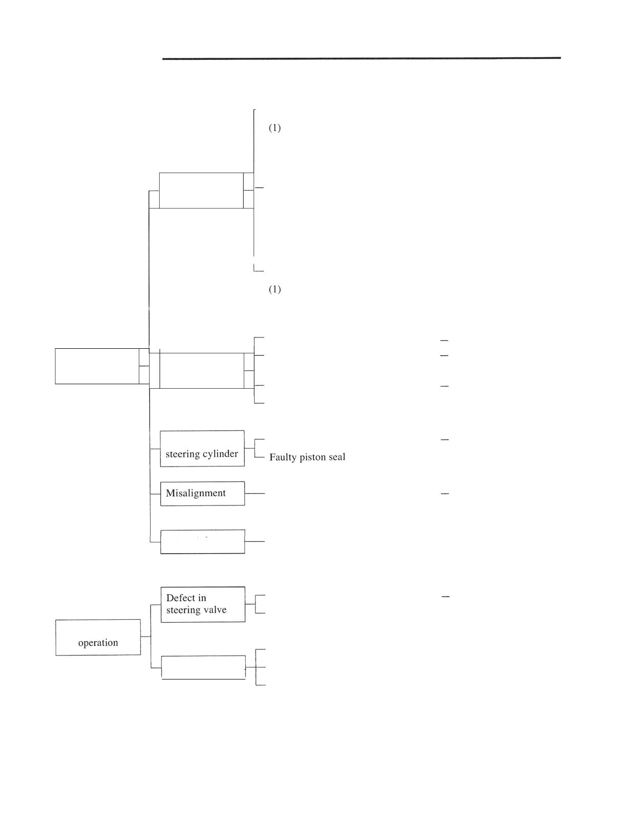
Troubleshooting
- No steering flow
Foreign materials clogged in spool -
Disassemble and clean.
pit
(2) Fatigued or damaged spring in the
- Replace spring.
spool
Defect in flow
Malfunction of relief valve
priority valve
(1) Low relief pressure
- Adjust relief pressure.
(2) Damaged valve seating surface
-
Replace valve assembly.
(3) Fatigued or damaged spring
- Replace springs and
adjust relief pressure.
Oil leak from relief valve
Damaged O-rings on the valve
- Replace O-rings.
body circumference
Clogging in "Gerotor"
Disassemble and clean.
Malfunction by spool seizure
Replace.
Stiff steering
Defect in
-
due to foreign material
wheel operation
steering valve
Damaged bearing
Replace.
Excessive tightening of end cap bolt
- Reassemble.
Repair or replace.
Defect in
Bent piston rod
- Replace.
Faulty installation of steering valve to
Readjust.
tilt column
Other defects
Flattened pipe
-
Replace.
Defect in
Seizure of spool or sleeve
Replace.
steering valve
Breakage of centering spring
- Replace.
Unstable steering
Trapped air
- Bleed.
Other defects
Flattened pipe
- Replace.
I
Faulty piston seal of steering cylinder
- Replace.
STEERING SYSTEM
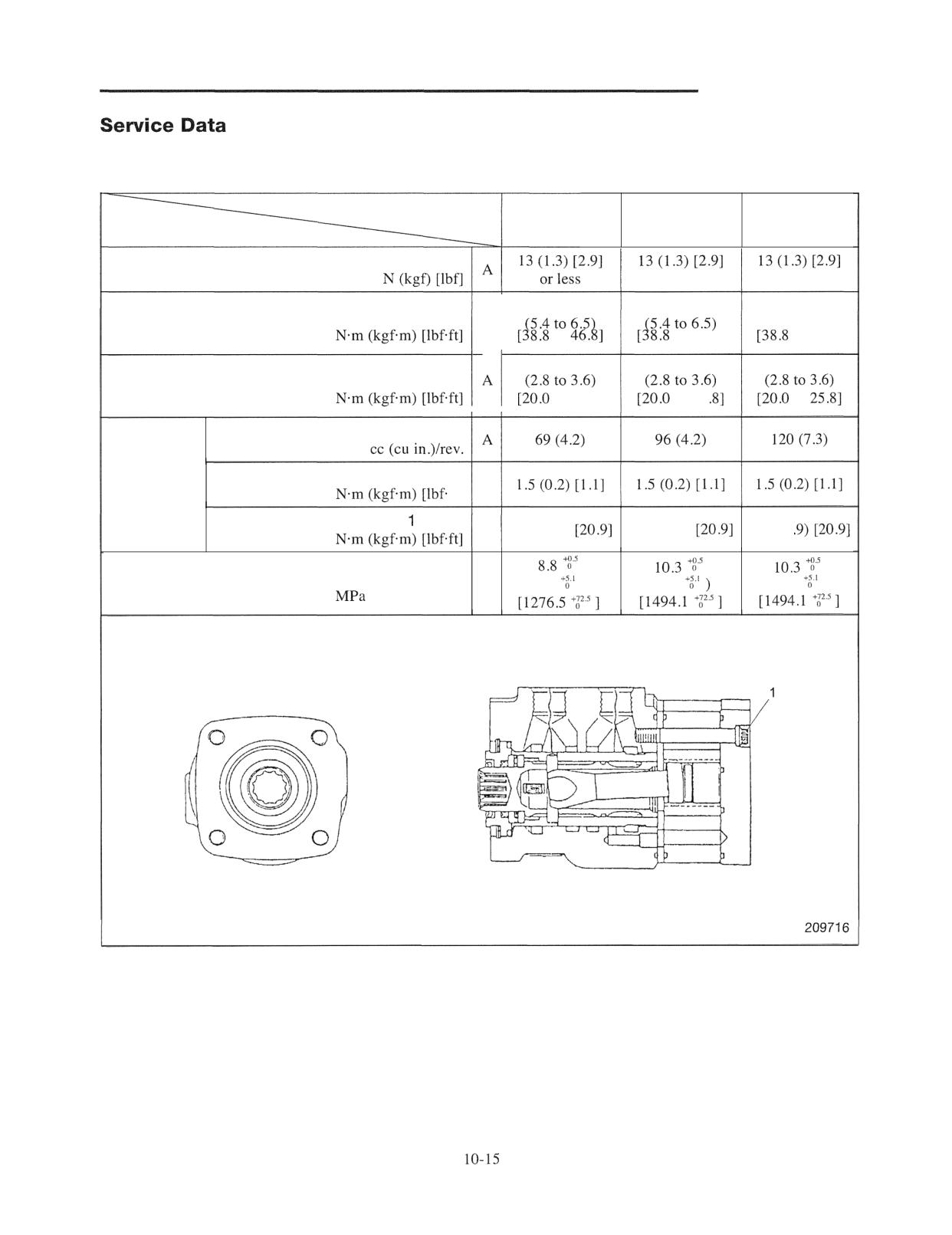
A: Standard value
Truck Models
1 ton class
2 ton class
3 ton class
Items
Steering effort (at steering wheel rim)
or less
or less
52.6 to 63.5
52.6 to 63.5
52.6 to 63.5
Tightening torque of steering wheel nuts
A
(5.4 to 6.5)
to
to 46.81
to 46.81
27 to 35
27 to 35
27 to 35
Tightening torque of steering bracket bolts
to 25.81
to 25
to
Displacement
Rotating torque in normal operation
Steering valve
A
ft]
Tightening torque of cap bolt
A
28 4 (29 )
28 4 (29 )
28.4 (2
Steering system relief valve set pressure
A
(90
)
(105
(105
)
(kgf/cm2) [psi]
SYSTEM
Structure and Functions
I
I
Outline
11
1
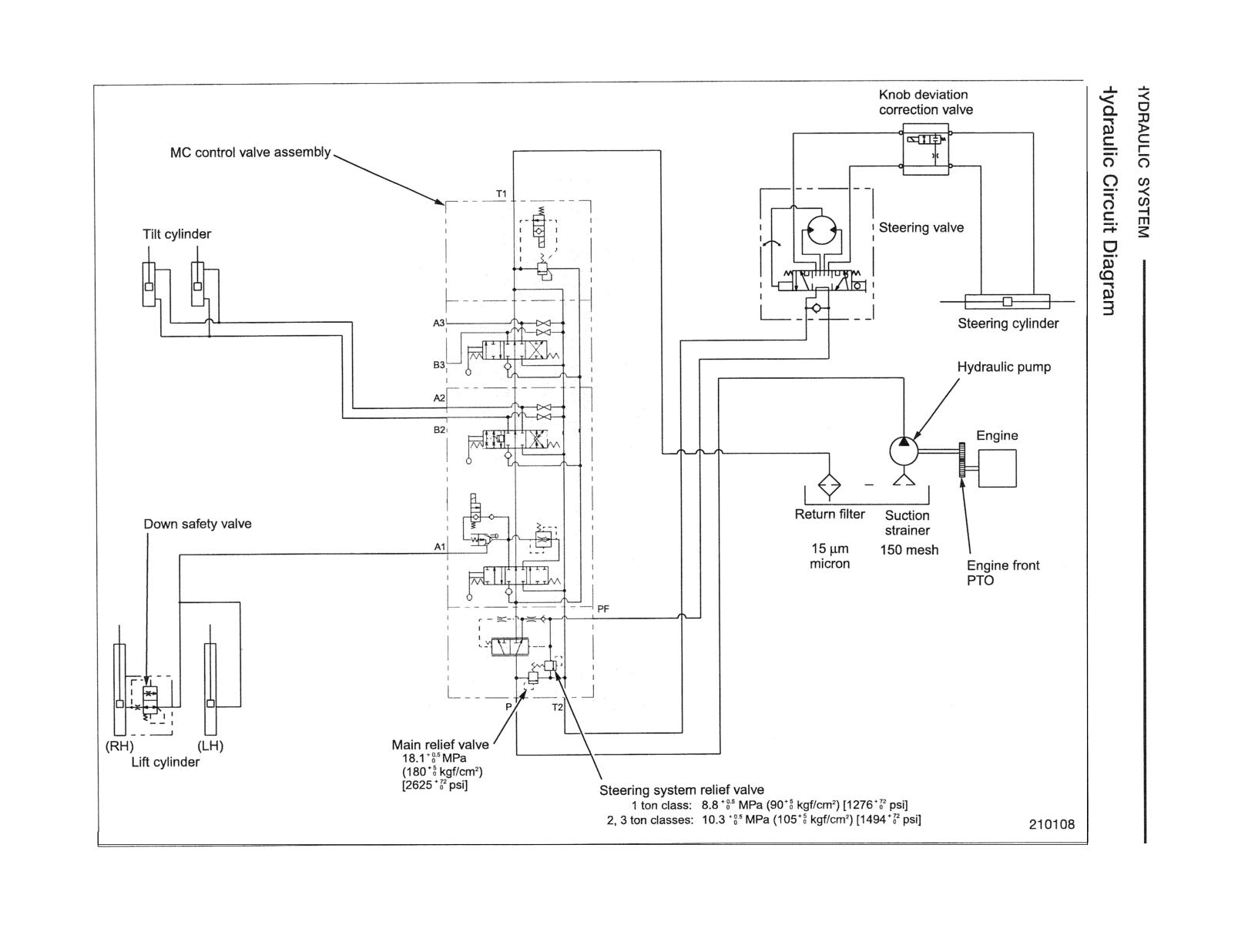
Hydraulic Circuit Diagram
11
2
Hydraulic Tank
11 -
3
Hydraulic Pump (Gear Pump)
11 -
4
Control Valve
11
5
Down Safety Valve
11 -
6
Lift Cylinder
11
7
Tilt Cylinder
11
13
Disassembly and Reassembly
14
Hydraulic Pump
11 - 14
Removal and Installation
11
14
Disassembly and Reassembly
11 - 15
Lift Cylinder
11 - 17
Removal and Installation
11 - 17
Disassembly and Reassembly
11 - 23
Tilt Cylinder
11 - 26
Removal and Installation
11
26
Disassembly and Reassembly
11 - 27
Flow Regulator Valve
11 - 29
Disassembly and Reassembly
.......................... 11 - 29
Piping
11 - 30
Suction Strainer and Return Filter
11 - 31
Removal and
11 - 31
Inspection and Adjustment
- 32
1. Hydraulic Tank
11 - 32
2. Control Valve
11 - 33
3. Descent Test
11
34
4. Forward Tilt Test
34
Troubleshooting
-
38
Control Valve
11 -- 43
HYDRAULIC SYSTEM
Structure and Functions
Outline
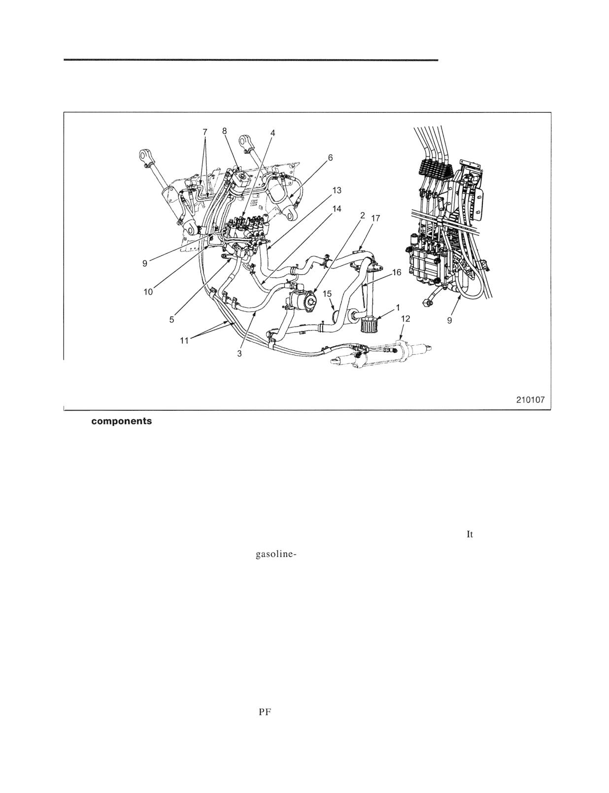
The illustrations show the load handling (pump motor) hydrauric system
on a 2 ton class truck with S4S diesel engine.
Main
1 Pump suction strainer:
10 Return line from steering valve
150 mesh metal strainer.
11 Oil feed line to steering valve
2 Hydraulic pump (gear pump):
12 Steering cylinder
A regular gear pump is directly coupled to the
13 Return line
engine PTO. See the "Hydraulic Pump" section
for details.
14 Line leading to top of lift cylinder piston:
This line is only installed in truck that have a lift
3 Hydraulic pump delivery hose:
cylinder with a return line.
is not installed in
The shape of this hose for the diesel-engine
trucks with 3.3 m (10.8 ft) or smaller lift. If this
models is different from that of the
line is not installed, the branching hole from
engine models, as the hydraulic pump locations of
return line 13 is closed with a blind plug.
these two models are different.
15 Return filter
4 Hydraulic control valve:
This cartridge-type filter should be replaced at
This valve has a built-in flow regulator valve.
every oil change.
5 Oil feed line to lift cylinder:
16 Level gauge
6 Tilt cylinder
17 Oil filter cap
7 Piping to tilt cylinder
8 Steering valve
9 Oil feed line to steering valve P port:
This line constitutes a part of the
flow
passage.
HYDRAULIC SYSTEM
Hydraulic Tank
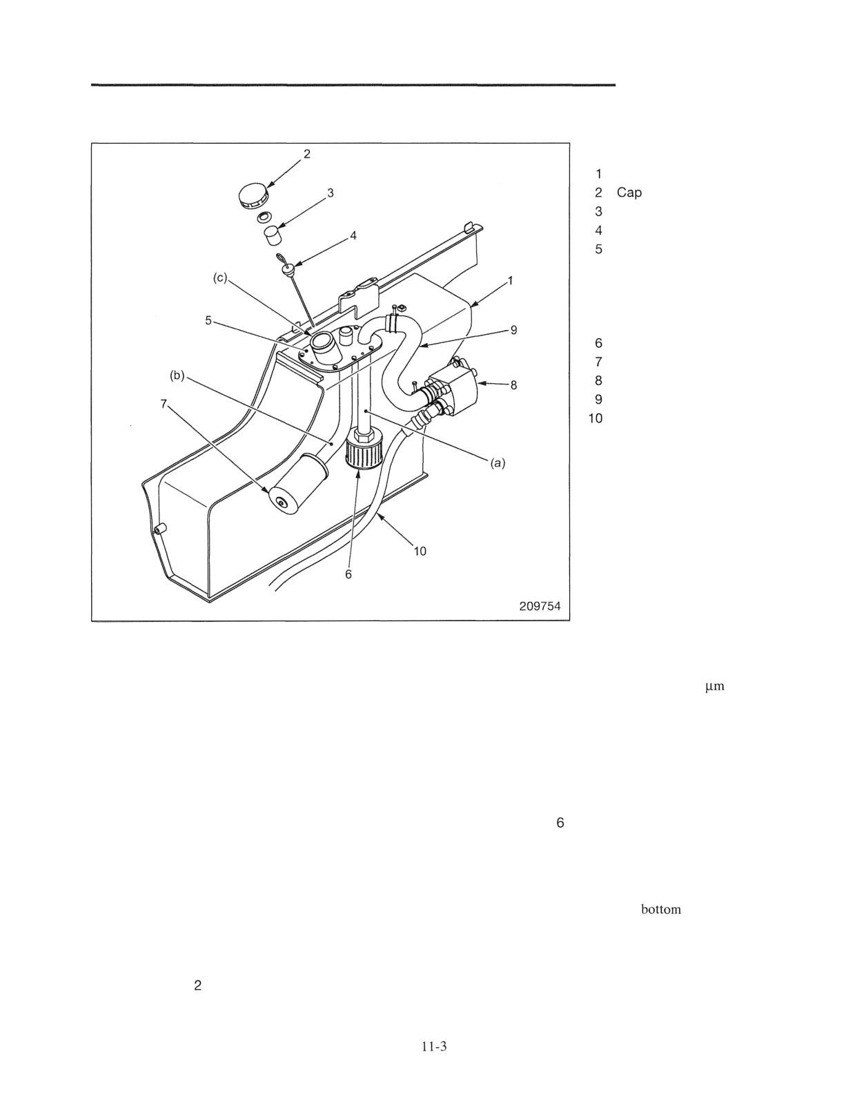
Main components
Hydraulic tank
Element
Level gauge
Tank cover
Parts welded to tank cover
(a) Suction pipe
(b) Pipe for return line
(c) Pipe for level gauge
Suction strainer
Return filter
Hydraulic pump
Pump suction line
Pump delivery line
The hydraulic tank is located in the center of the right
Return filter 7 is attached to the end of return pipe (b).
side of the frame and composes a part of the frame
The return filter is a cartridge type of 15
with an
structure.
integral relief valve. When the filter is clogged, the
relief valve activates and discharges unfiltered oil to the
Three pipes of (a),(b) and (c) are welded to tank cover
tank. Periodic replacement is important. In case of a
5 and to the end of each pipe are installed suction
new truck or a large-scale overhaul involving parts
strainer 6, return filter 7, level gauge 4 and cap 2.
replacement, replacement of the oil filter after the first
Therefore, parts in the tank can be taken out as an
month is recommended.
assembly if the tank cover is removed. Replacement of
the filter and cleaning of the strainer can be easily
Suction strainer of the pump is 150 mesh screen
carried out if tank cover 5 is removed.
gauze. When replacing oil, clean the suction strainer.
Level gauge 4 is inserted in pipe for a level gauge (c)
In case of a wet-type single disc clutch truck, the return
and the opening of pipe (c) is blocked with cap 2 with
oil line is installed to the side of the tank.
an element.
The drain plug is installed at the
of the tank.
Air moving in and out of the tank caused by fluctuation
of oil level in the tank during operation occurs through
two air holes provided on the side of cap 2. Element 3
assembled in cap is a filter to prevent outside polluted
air from entering the tank.
SYSTEM
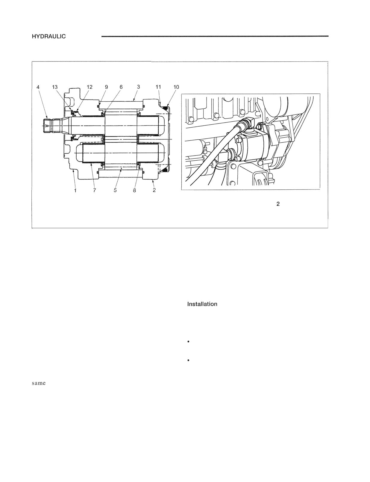
Hydraulic Pump (Gear Pump)
I
Pump installed on engine
(example: S4S diesel engine, ton class)
209755
1 Front cover
8 Gasket (shaped like 3)
2 Rear cover
9 Gasket
3 Body
10 Hexagon socket head bolt
4 Drive gear
11 Washer
5 Driven gear
12 Shaft seal
6 Side plate
13 Snap ring
7 Bushing
Type of pump
of pump
The pump in a standard truck is a single-gear pump as
The pump is directly installed to the engine front PTO,
shown in the above illustration.
but installed sides are reversed left to right for a
gasoline engine and a diesel engine.
A low-noise type pump is available as an option. This
low-noise type has reduced noises produced by
Gasoline engine: The pump is installed to the left side
discharge pressure pulsation by making backlash
viewed from the flywheel side.
between gears smaller, and thus leak amount between
Diesel engine: The pump is installed to the right side
gears smaller compared to a normal type. The
viewed from the flywheel side.
appearance and structure of the low-noise type are the
as those of the standard type except for the
Piping around pump
number of teeth.
As the installed location of the pump is different
between the gasoline engine and diesel engine, shapes
of the suction piping and delivery piping around the
pump are different.
HYDRAULIC SYSTEM
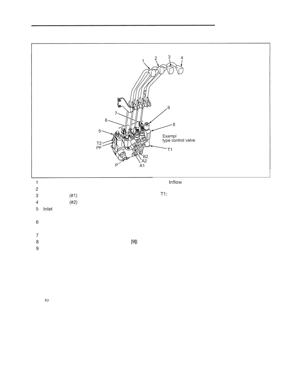
Control Valve
e of four-valve
210109
Lift control lever
P:
port of pump pressure oil
Tilt control lever
PF: Supply port of pressure oil to steering system
Return port to tank
Attachment
control lever
T2: Return port from steering system
Attachment
control lever
Al: Port to lift cylinder
cover section (with built-in flow priority
A2: Port to tilt cylinder rod
valve)
B2: Port to tilt cylinder head
Combination section (with built-in lift valve, tilt
valve and flow divider valve)
Attachment section
End section (with built-in unloader valve
Unloader valve (with solenoid)
Most parts of this hydraulic valve move mechanically.
When the operator moves the control levers (1 through
4), the spool valve moves up and down and supplies and
returns pressure oil to corresponding hydraulic cylinders.
For detailed structure and operation, and disassembly and
reassembly, refer to the "Control Valve" section (pages
11-43
11-58).
HYDRAULIC SYSTEM
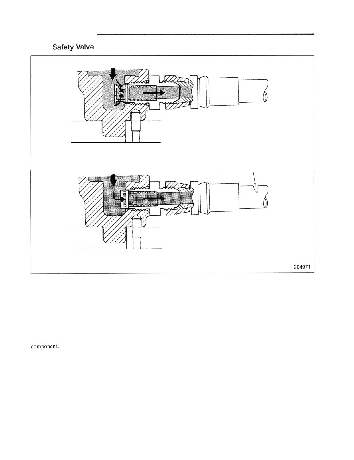
Down
I
When in normal condition
Broken area
When piping is broken
The down safety valve is located at the bottom of the
right lift cylinder.
This valve is a safety valve which regulates the flow of
oil to prevent the forks from moving down too quickly
if the piping between the lift cylinder and the flow
regulator valve is broken. Also if the flow of return oil
from the lift cylinder becomes excessive due to a
maladjusted regulator valve or a fault of another
HYDRAULIC SYSTEM
Lift Cylinder
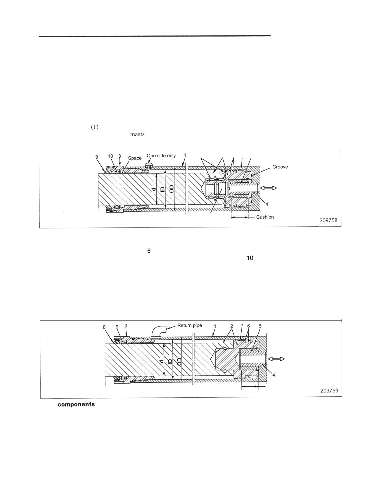
1. Second lift cylinder for simplex mast and triplex mast
There are two types for the above lift cylinder: one with a return pipe and the other without a return pipe. The
lift cylinder without a return pipe is provided with a check valve in the piston instead of a return pipe. This is
called an internal drain type cylinder.
Regardless of presence or absence of a return pipe, the bottom of the piston is provided with a cushion
mechanism for soft landing.
(1) Cylinder without a return pipe
Mast used:
Simplex mast with raised height of 3.4 m (11.2 ft) or less
(2) All triplex
Detail of inside
Groove
2
7
8
5
Inflow and
outflow of oil
6
stroke:
23 mm (0.91 in.)
Main components
1 Cylinder tube
5 Cushion bearing
8 Bushing
2 Piston rod assembly
Check valve
9 Wiper ring
3 Cylinder head
7 U-ring, Backup ring
X-ring
4 Pipe (integrated with cylinder
tube)
2. Cylinder with a return pipe
Mast used: Duplex mast with raised height of 3.5 m (11.5 ft) or higher
Detail of inside
Inflow and
outflow of oil
cushion stroke:
23 mm (0.91 in.)
Main
1 Cylinder tube
5 Cushion bearing
8 Wiper ring
2 Piston rod assembly
6 U-ring, Backup ring
9 U-ring
3 Cylinder head
7 Bushing
4 Pipe (integrated with cylinder
tube)
HYDRAULIC SYSTEM
Cylinder dimensions (The cylinder length and stroke vary depending on raised height )
Unit: mm (in.)
Model
1 ton class
2 ton class
3 ton class
3.5 m (11.5 ft) or higher
45 (1.77)
55 (2.16)
63 (2.48)
23 (0.91)
Yes
Triplex
45 (1.77)
55 (2.16)
63 (2.48)
23 (0.91)
No
Cushion mechanism when piston descends
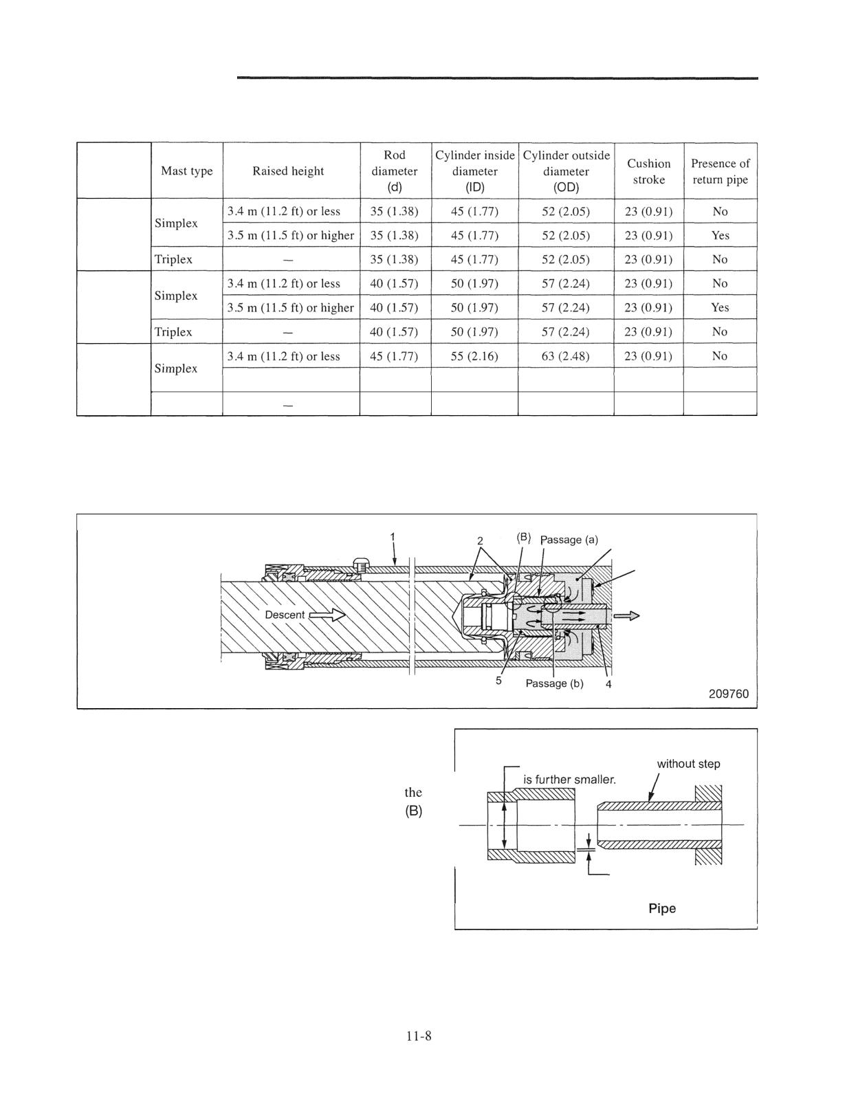
Action during piston descent
Entrapped oil (A)
Groove
Outflow
The above illustration shows a condition in which piston
Outside diameter
rod assembly 2 descends with its self weight and pipe 4
The inside diameter
and cushion bearing 5 are beginning to fit in. Cushion
bearing 5 is pushed upward by entrapped oil (A) and
piston and cushion bearing 5 make surface contact at
area. This blocks the passage (a). The only outflow
passage for entrapped oil (A) is clearance (b) between the
bore of cushion bearing 5 and the outside of pipe 4. This
Clearance of approx.
passage (a) becomes narrower as the piston descends
0.1 mm (0.004 in.)
further. Therefore, the descending speed of the piston
Cushion bearing
209761
becomes gradually slower and impulsive contact is
avoided.
Image of pipe and cushion bearing
HYDRAULIC SYSTEM
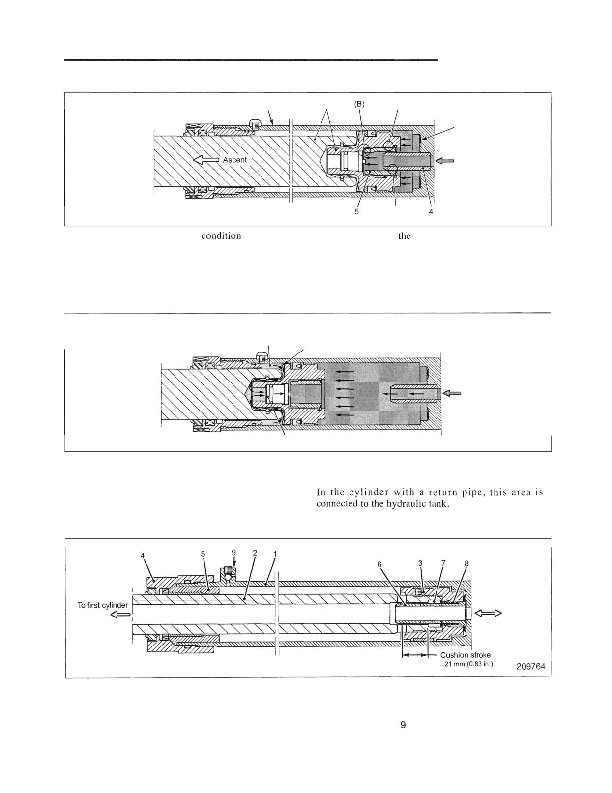
Action during piston ascent (initial stage)
1
2
Passage (a)
Groove
Inflow
Passage (b)
209762
The above illustration shows a
immediately
This action opens
(B) area, causing the passage (a)
after the piston rod assembly ascends. Oil that flows in
to open. Oil from the passage (a)and passage (b) which
acts on the center of the piston, ascending piston rod
opens from the beginning flows in the piston bottom,
assembly 2 slightly. At the same time, cushion bearing
acting on the entire bottom surface of the piston and
5 descends by being pushed by oil that flows in.
pushing piston rod assembly 2 upward.
Cylinder of internal drain type
Entrapped oil and air
(There normally tends to be
negative pressure in this area.)
Groove
\ Check valve
209763
The above illustration shows a condition in which the
and discharges oil and air to pressure oil (internal
piston rod assembly ascends to the vicinity of the
drain).
highest position. When pressure of oil and air
entrapped between the rod and cylinder exceeds the
set pressure of the check valve, the check valve opens
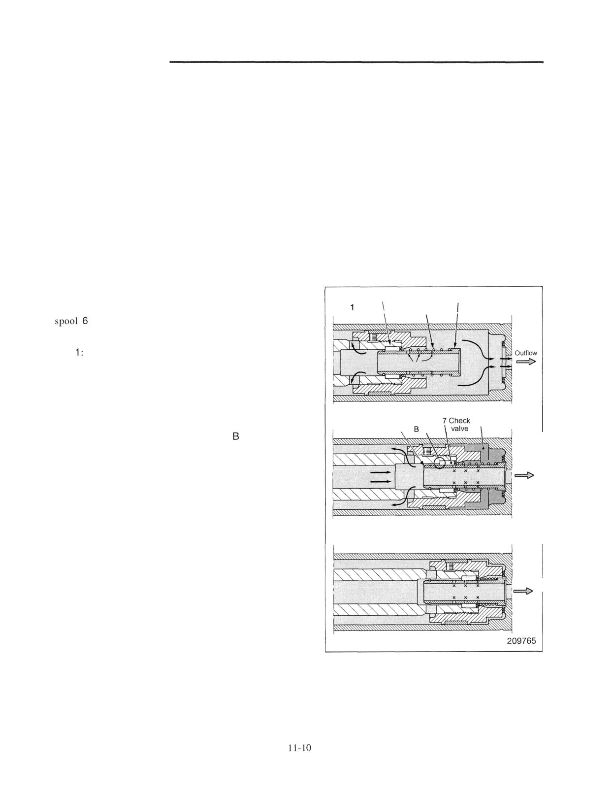
2. Second lift cylinder for duplex mast
Inflow and outflow
Main components
1 Cylinder tube
4 Holder
7 Check valve
2 Rod
5 Cylinder head
8 Spring
3 Piston
6 Cushion spool
Bleed valve
HYDRAULIC SYSTEM
Action
Pressure oil first flows through the hollow area inside
piston rod 2 and enters the first lift cylinder. As the inside
diameter of the first lift cylinder is larger than that of the
second lift cylinder, the first lift cylinder ascends first. The
second lift cylinder starts to ascend after the first lift
cylinder has completed ascent.
This cylinder is provided with a cushion mechanism which
prevents the piston bottom from impulsively contacting the
cylinder bottom during piston descent. (Refer to the
illustration below.)
Bleed valve 9 is a valve for bleeding air when the hydraulic
system is overhauled.
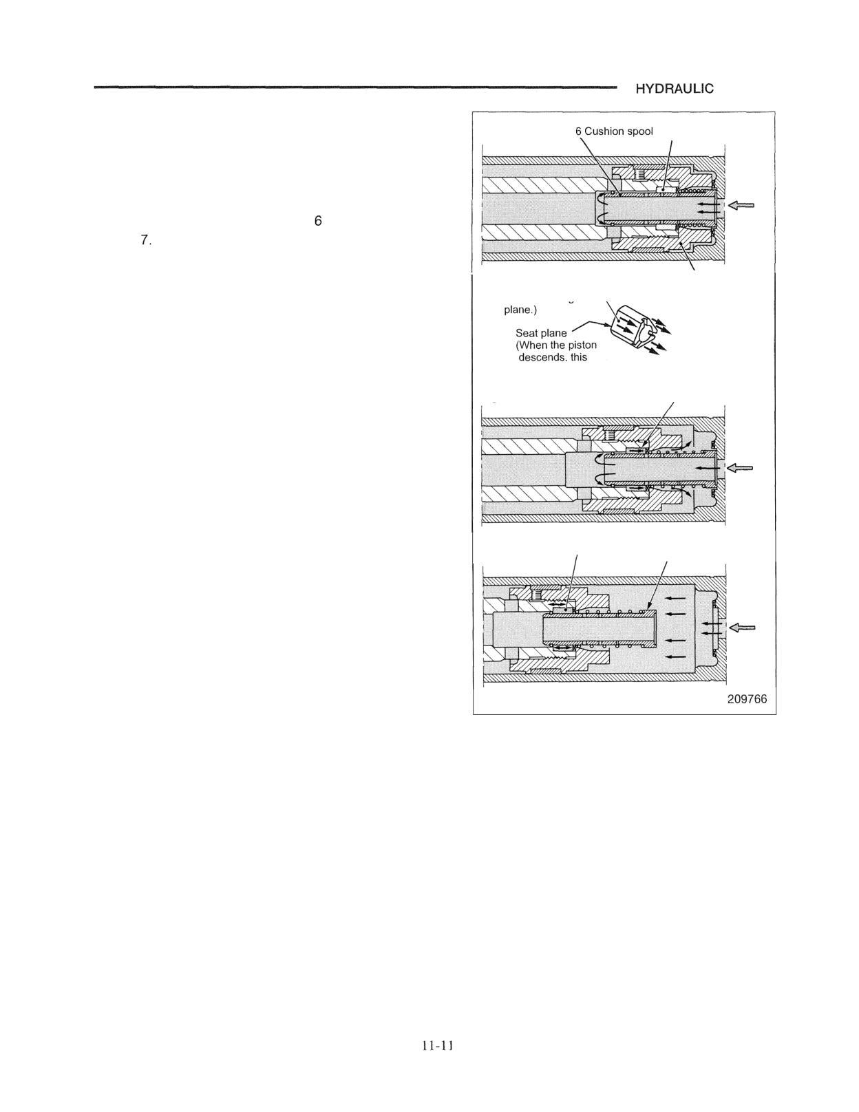
Action during piston descent
7 Check valve
6 Cushion spool
The illustration on the right explains movement of cushion
Fig.
8 Spring
when the piston descends. (To the right of the
illustration is the piston bottom.)
Fig. This illustration shows a condition in which
cushion spool 6 does not contact the cylinder
bottom. Cushion spool 6 extends out by spring 8.
Fig. 2: This illustration shows a condition in which
cushion spool 6 contacts the cylinder bottom and
6 Cushion spool
gets under check valve 7 slightly. The check valve
Fig. 2
Entrapped oil (A)
\
area
moves to the left, blocking the
area. Oil (A)
below the underside of the piston is discharged
through holes (two rows on the right) of cushion
Outflow
spool 6.
For the shape of the check valve, refer to the image
drawing on the following page.
Fig. 3: As the piston descends, cushion spool 6 gets under
check valve further. As a result, the number of
Fig. 3
holes through which oil can pass decreases and
discharge of entrapped oil (A) is restricted. The
descending speed of the piston becomes slower and
Outflow
impulsive contact is avoided.
SYSTEM
Action during piston ascent
Fig. 4
7 Check valve
The illustration on the right explains movement of the
check valve when the piston ascends.
Fig. 4: The illustration shows a condition immediately
Inflow
before piston ascent. Oil which flows through the
hollow area in cushion spool acts on check valve
Fig. 5: Pressure oil pushes check valve 7 to the right.
Pressure oil flows along the plane of the check
Initial stage of ascent
3 Piston
(Oil flows alona this
\
valve and flows to the underside of the piston. The
"triangular shape" of check valve 7 is designed to
Shape of
increase the initial inflow volume.
check valve
The piston starts to ascend.
plane seats.)
Fig. 6: The illustration shows a condition in which cushion
Fig. 5
7 Check valve
spool 6 has left the cylinder bottom and is
ascending.
Inflow
7 Check valve
6 Cushion spool
Fig. 6
I
Inflow
HYDRAULIC SYSTEM
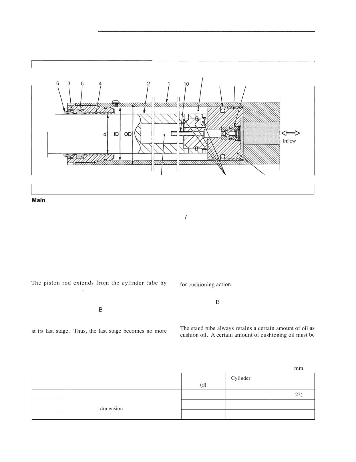
3. First cylinder for duplex mast and triplex mast
Detail of inside
Space (B) Cushion oil is filled in this area.
7
8
9
and
outflow
Air chamber (A)
Oil passage
Piston
I
I
209767
components
1 Cylinder tube assembly
6 Wiper-ring
2 Piston rod assembly
Seal ring assembly
3 Cylinder head
8 Slide ring
4 Bushing
9 Check valve
5 U-ring
10 Stand tube
Action
This cylinder, mounted on the center of the mast, acts
In the descending stroke of the piston rod, cushion oil
first during ascending stroke of the fork.
in air chamber A is sucked in space B. The air
chamber, stand tube, and check valve are related parts
pressure oil acting on the piston bottom. For
prevention of an impulsive approach of the piston and
Extra leaked oil which leaks from around the piston and
the cylinder head at the last stage of its ascent, cushion
enters space
returns from stand tube 1 0 to the
oil is always filled in space between the cylinder tube
cylinder bottom via check valve 9 at the last stage of
and the piston rod. When the piston rod ascends, it
cylinder ascending.
ascends while pushing out cushion oil to air chamber A
impulsive.
filled in the overhauled cylinder.
Cylinder dimensions (The cylinder length and stroke vary depending on raised height )
Unit:
(in.)
Rod diameter
inside
Cylinder outside
Truck model
Mast type
diameter (ID)
diameter (OD)
1 ton class
55 (2.16)
70 (2.76)
82 (3
Cylinders for the duplex mast and the triplex mast
2 ton class
55 (2.16)
75 (2.95)
86 (3.39)
are of the same
and same type.
3 ton class
65 (2.56)
90 (3.54)
105 (4.13)
HYDRAULIC SYSTEM
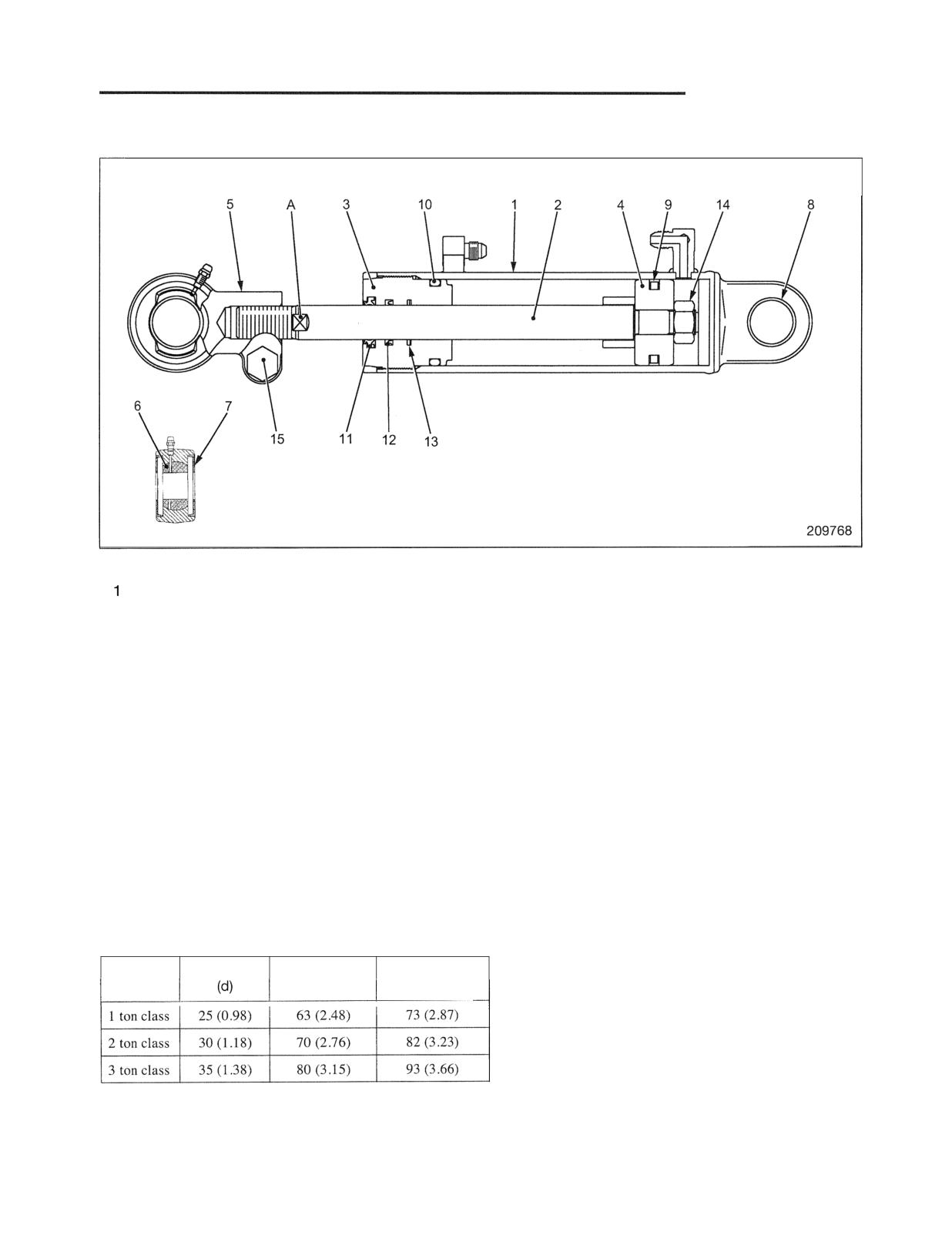
Tilt Cylinder
Main components
Cylinder
5 Socket
9 Piston seal
13 Buffer ring
2 Rod
6 Bearing
10 O-ring
14 Nut
3 Bushing guide
7 Seal
11 Dust seal
15 Clamp bolt
4 Piston
8 Bushing
12 Packing
The tilt cylinder is a double-acting type. To adjust right
and left imbalance of tilt angles when the mast is attached,
loosen the clamp bolt and turn the piston rod with a spanner
applied to its A area.
Seal 7 extends grease interval from the grease nipple.
Installation of this seal has extended grease interval to 500
service hours.
Cylinder dimensions (Cylinder length and stroke vary
depending on tilt angles of forward and backward tilt. )
Unit: mm (in.)
Truck
Rod diameter
Cylinder inside
Cylinder outside
model
diameter (ID)
diameter (OD)
I
I
I
HYDRAULIC SYSTEM
Disassembly and Reassembly
Hydraulic Pump
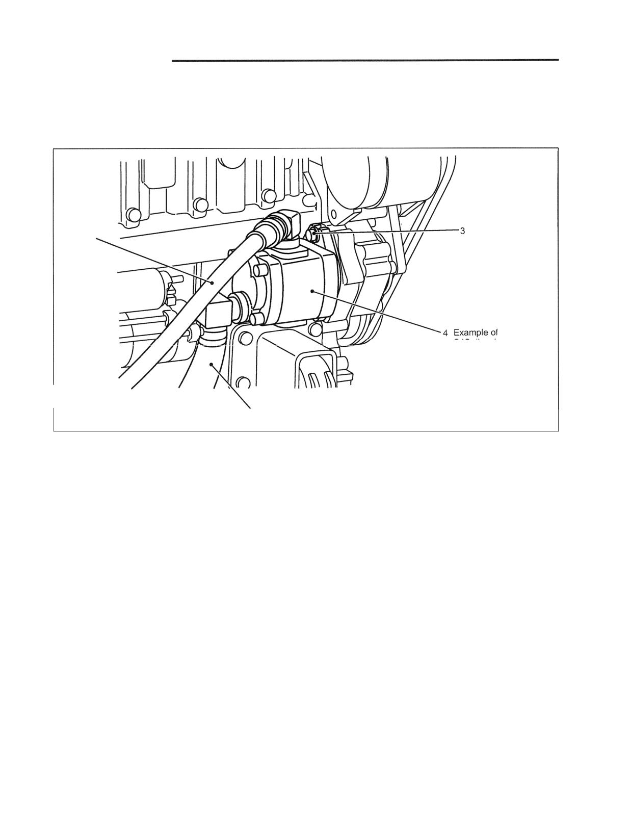
Removal and Installation
1
S4S diesel engine
2
209769
Sequence
1 Pump delivery hose
3 Pump mounting bolt
2 Pump suction hose
4 Pump
Suggestion for Removal
Installation
Precautions for removal:
To install, follow the reverse of removal sequence, and
do the following steps:
(1) The installed positions and sizes of the suction hose
and delivery hose differ by model.
(1) Apply grease to the spline of the pump shaft before
installation.
(2) Cover the pump and its surroundings with shop
cloths in preparation for spilled oil.
(2) Insert the gasket (diesel engine) or O-ring (gasoline
engine) between the pump and engine PTO.
(3) Take care not to allow foreign particles to enter the
pump and hose from detached parts.
(3) Perform test operation after installing the pump.
Refer to page 11-16.
HYDRAULIC SYSTEM
Disassembly and Reassembly
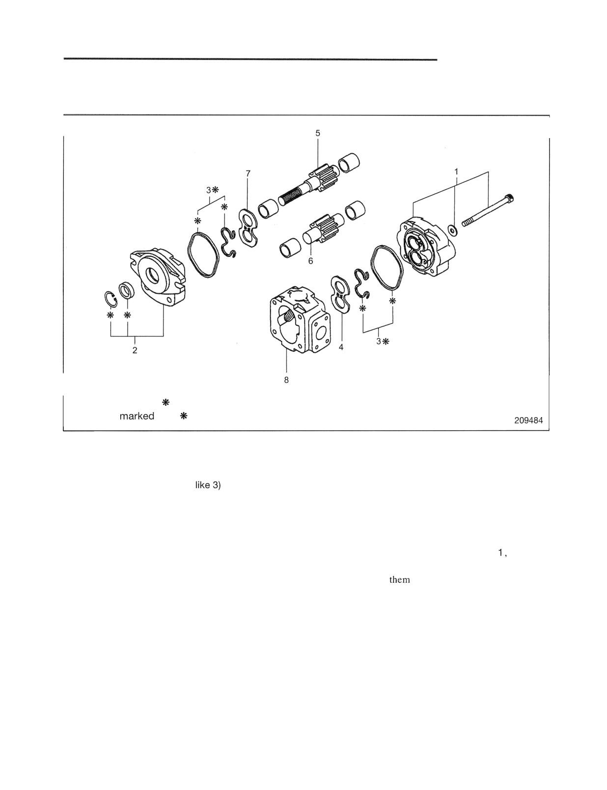
Disassembly
Parts marked with are components of the seal kit.
Parts not
with are non-deliverable parts.
Sequence
1 Rear cover, Bolt, Washer, Bushing
5 Drive gear
2 Front cover, Snap ring, Shaft seal, Bushing
6 Driven gear
3 Gasket, Gasket (shaped
7 Side plate
4 Side plate
8 Body
Note: (1) The hydraulic pump is to be overhauled by
Suggestions for Disassembly
the manufacturer. Where it has to be
(1) As front cover 2 and rear cover
made of
overhauled in field, be sure to follow the
aluminum alloy, get easily scratched, do not
suggestions for disassembly. Remember,
forcibly tap
with a hammer. Use a wooden
field overhauling will release the
hammer or plastic hammer.
manufacturer from any warranty claims.
(2) When disassembling, do not remove the body, gear
(2) Do not remove oil seal 2 and bushings
and bushing by forcibly tapping them with a
unless they are defective to require
hammer.
replacement.
(3) Place disassembled parts in orderly sequence.
Especially, do not mistake the relative position of
the gear and bushing side plate.
HYDRAULIC SYSTEM
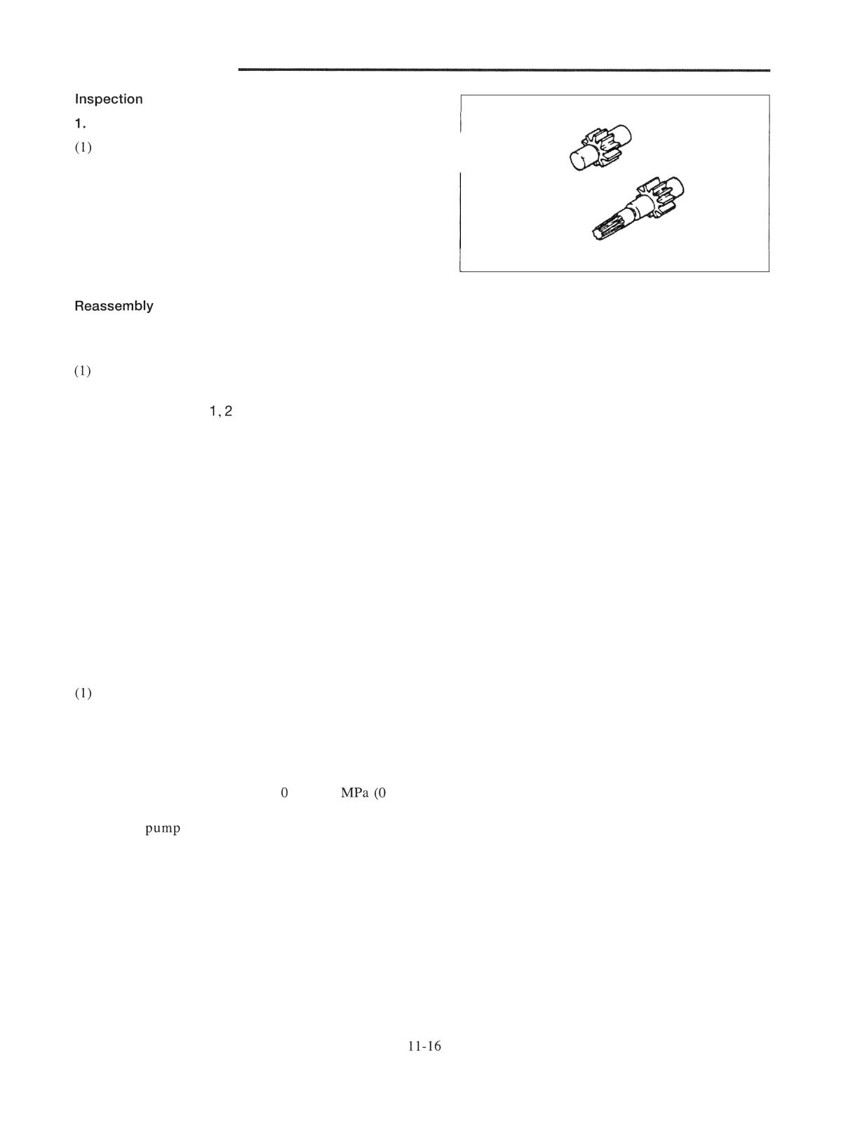
and Repair
Drive and driven gears
Check the gear teeth for wear, chipping or other
defects.
(2) Check the side faces of the gears for wear or damage.
(3) Check the shafts for wear or damage.
2. Covers, body and bushings
Check these parts for wear or damage.
200344
To reassemble, follow the reverse of disassembly sequence,
and do the following steps:
Replace the seal kit parts with new ones.
(2) Completely remove oil or grease on the mating
surfaces of covers
and body 8.
(3) Visually check all the parts for cleanliness and apply
hydraulic oil to the inside surface of the body before
reassembly.
(4) Apply grease to the lip of the shaft seal.
(5) Be careful not to give damage to the lip of shaft seal by
spline edges of drive gear 5.
(6) Tighten the bolts evenly and progressively.
(7) The pump is assembled properly if the pipe wrench
fitted on the pump shaft can be turned easily by hand.
Test operation
Perform test operation after installing the pump.
Check that the oil amount in the hydraulic tank is
sufficient.
(2) Attach a pressure gauge to the pump delivery hose.
Refer to page 11-33 "Main Relief Valve."
(3) Start the engine, raise the adjusting screw of the main
relief valve in sequence from to 18.1
to 180
kgf/cm2) [0 to 2625 psi], and check the temperature rise
of the
body by touching it by hand. If the
temperature rise of the pump body is substantial
compared to the oil temperature rise, disassemble again
for checking.
(4) Set the relief valve to the specified pressure.
(5) Measure the lifting speed of the fork under no load. If
the speed is to the specified value, the pump discharge
volume is normal.
(6) Check that the fork operates normally by raising and
lowering it under load.
HYDRAULIC SYSTEM
Lift Cylinder
Removal and Installation
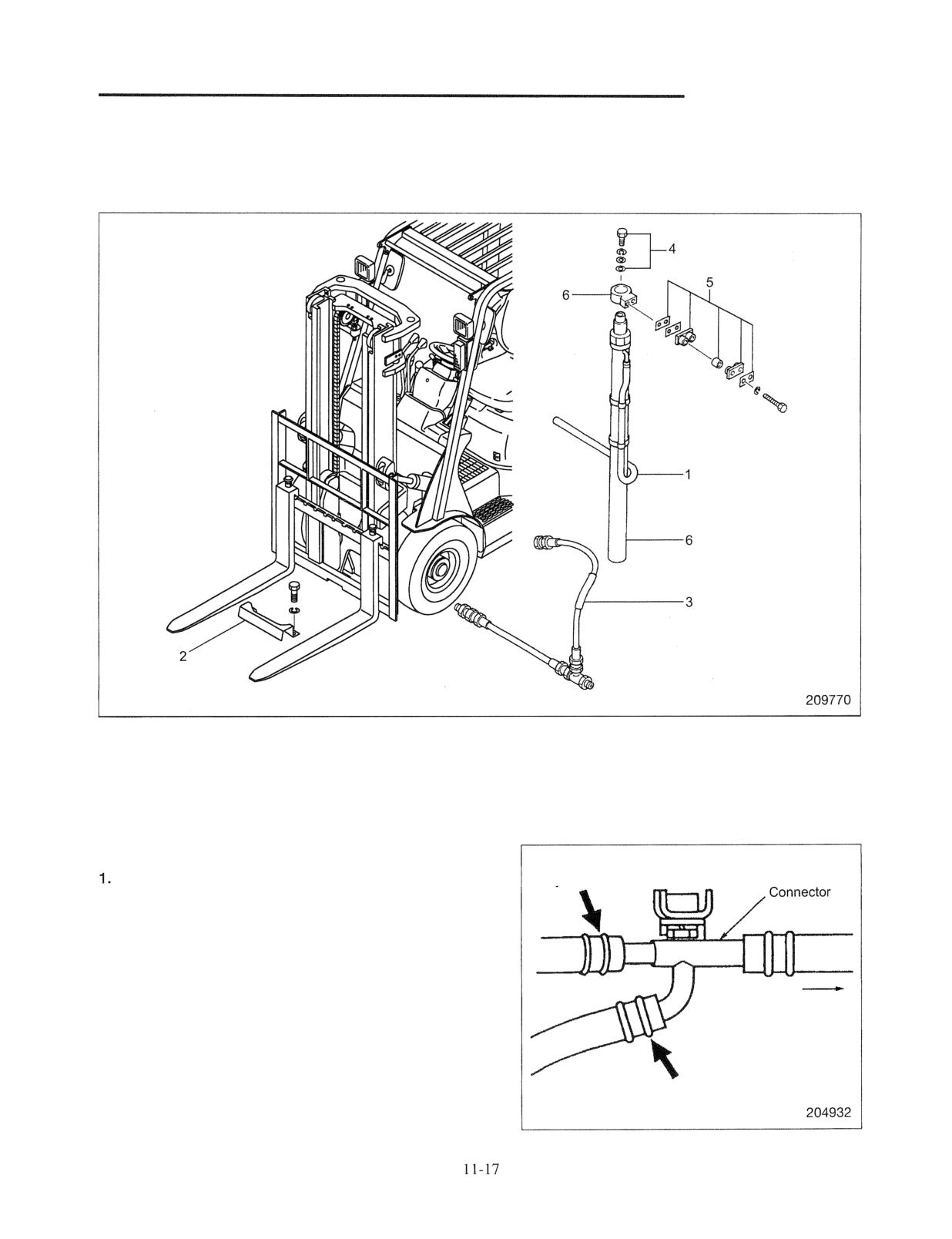
Simplex mast
Sequence
1 Hose guard
4 Set bolt, Shim
2 Return hose (if equipped)
5 Cylinder clamp (Cushion, Collar, Shim)
3 High-pressure hose
6 Lift cylinder, Bracket
Suggestions for Removal
From right-hand
Removal of hose guard
lift cylinder
Remove the hose guard from the front while the lift bracket
is placed at the bottom.
2. Removal of return hose (if equipped)
Start the engine, raise the lift bracket to the highest
To tank
position, and stop the engine. Then, remove return hoses
on the right and left cylinders from the connector.
Note: Place a drip pan below the connector to catch the oil.
From left-hand
lift cylinder
HYDRAULIC SYSTEM
3. Lowering of lift bracket
Gently operate the lift lever to lower the lift bracket.
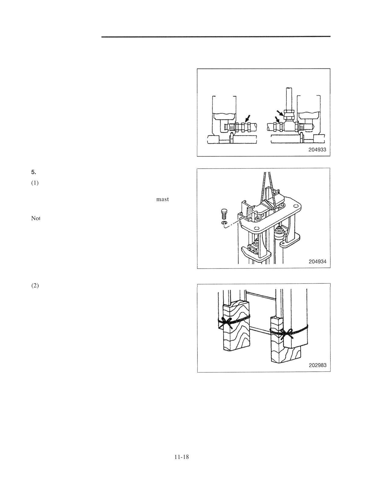
4. Disconnecting high-pressure hoses
Disconnect the high-pressure hoses at the joints indicated
Right-hand cylinder
Left-hand cylinder
by arrows. Use a drip pan to catch oil flowing out of the
hoses.
Removing set bolts
Remove the set bolt at the top of each lift cylinder. Lift
the inner mast to separate the cylinder rod ends. To lift
the inner mast, hitch a sling around the
with
protective rag.
:e: The rod end of either lift cylinder is shim adjusted
to eliminate the difference in stroke between the
cylinders. Before removing the set bolts, make a
record of the amount of shims fitted to each cylinder.
Tie wood blocks under the inner mast and detach the
sling. Use the blocks strong enough to support the
mast.
HYDRAULIC SYSTEM
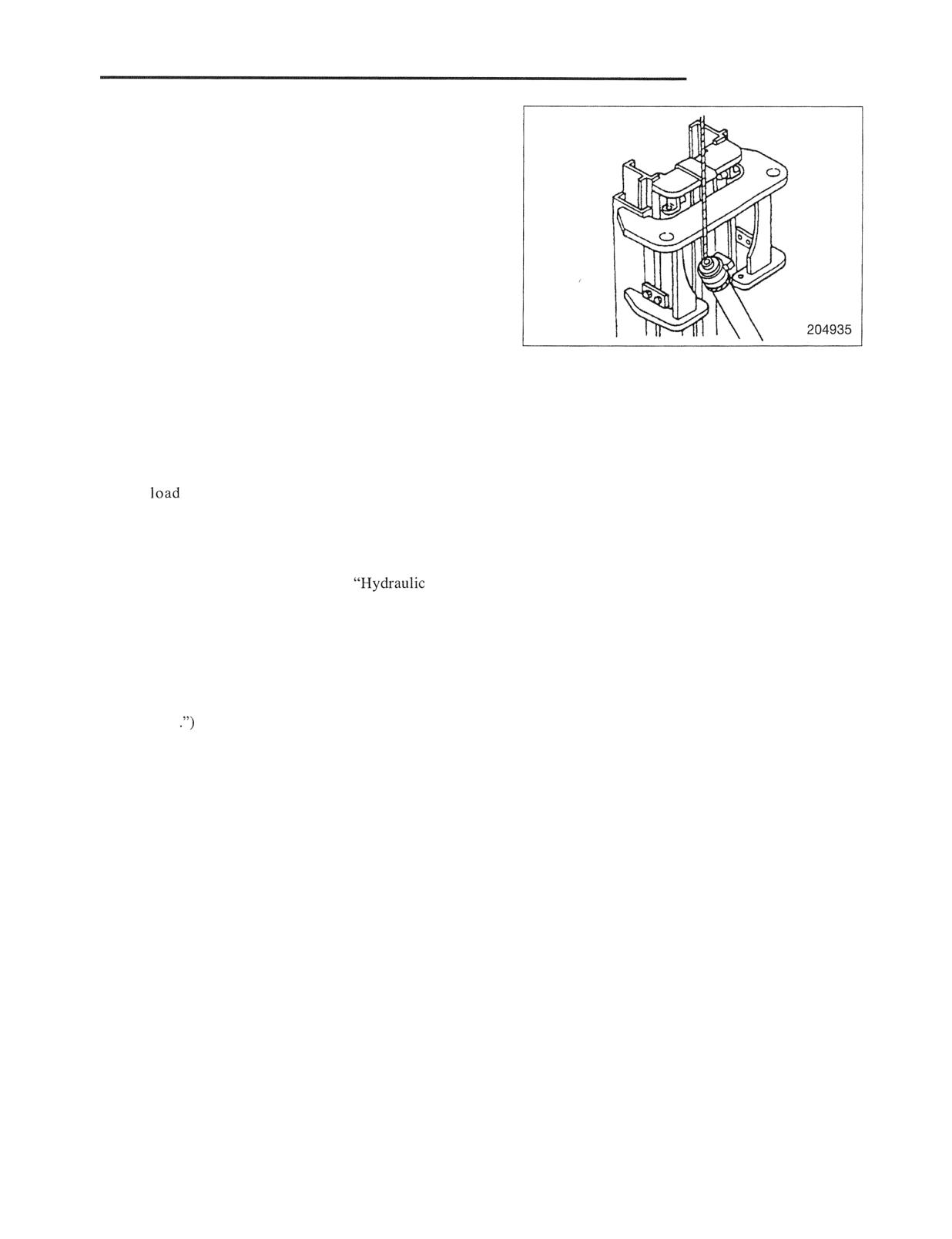
6. Removing lift cylinders
Attach a lifting sling before removing the cylinder clamp.
Lift the cylinder from the rear side of the mast, and remove
the cylinder.
Installation
To install, follow the reverse of removal sequence, and do
the following steps:
(1) Extend and retract the lift cylinders several times under
no
condition to bleed air out of the cylinder
circuits and to make sure that the cylinders moves
smoothly.
(2) Check the oil level in the hydraulic tank with an oil
level gauge. (Refer to the topics
Tank" in
the following section "Inspection and Adjustment.")
(3) Check the lift height.
(4) After the lift cylinders or piston rods have been
replaced, check for difference in stroke between the
two cylinders. (Refer to "GROUP 12 MAST AND
FORKS
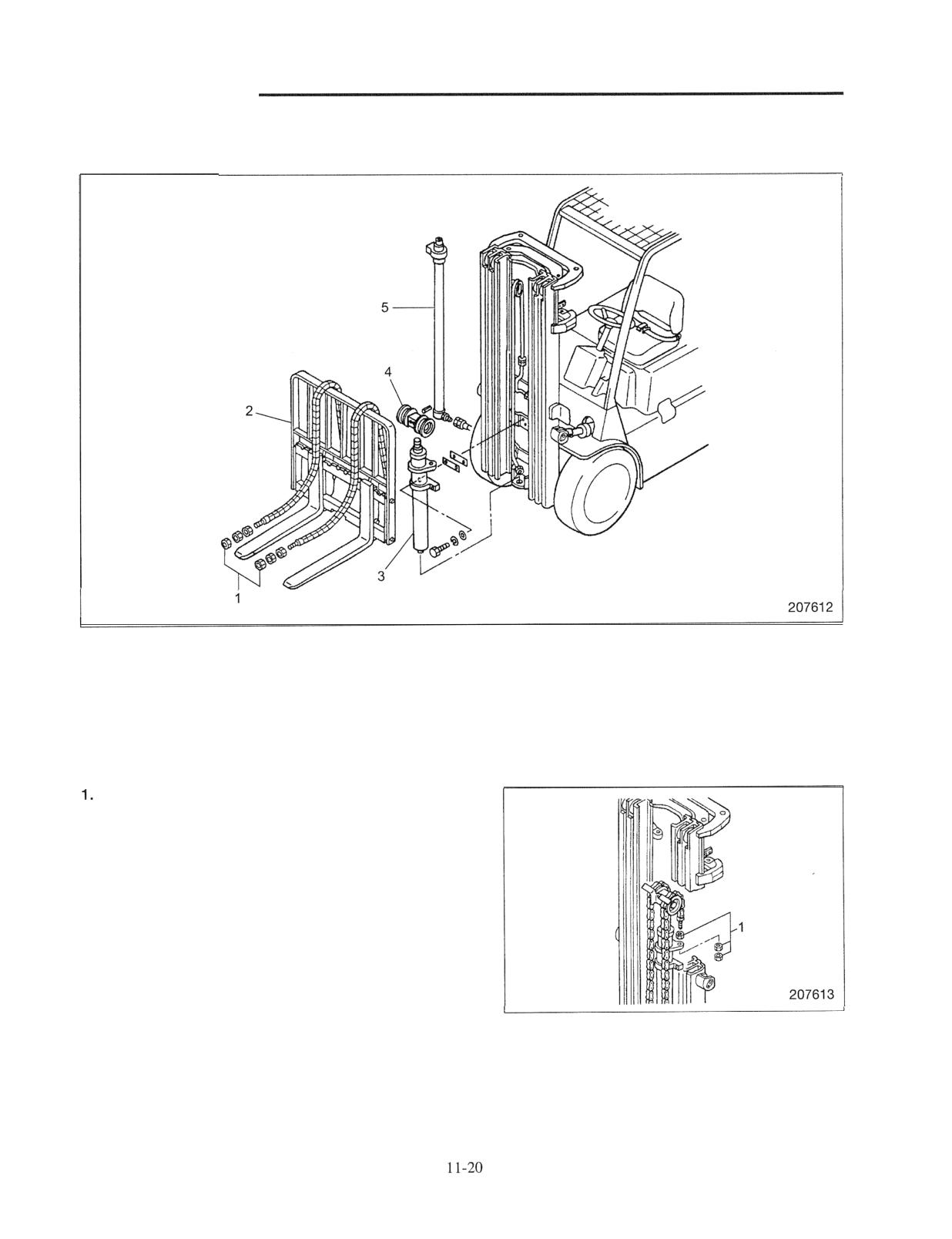
HYDRAULIC SYSTEM
Duplex and triplex mast removal
Note that the triplex mast is used as an example.
Sequence
1 Nuts
4 Chain wheel support assembly
2 Lift bracket assembly
5 Second lift cylinder
3 First lift cylinder
Suggestions for Removal
Removal lift bracket assembly
(1) Lower lift bracket assembly and place wood blocks
under the assembly. Tilt the mast forward, lower the
inner mast to the bottom, then remove nuts 1 from the
anchor bolts of the first lift chains.
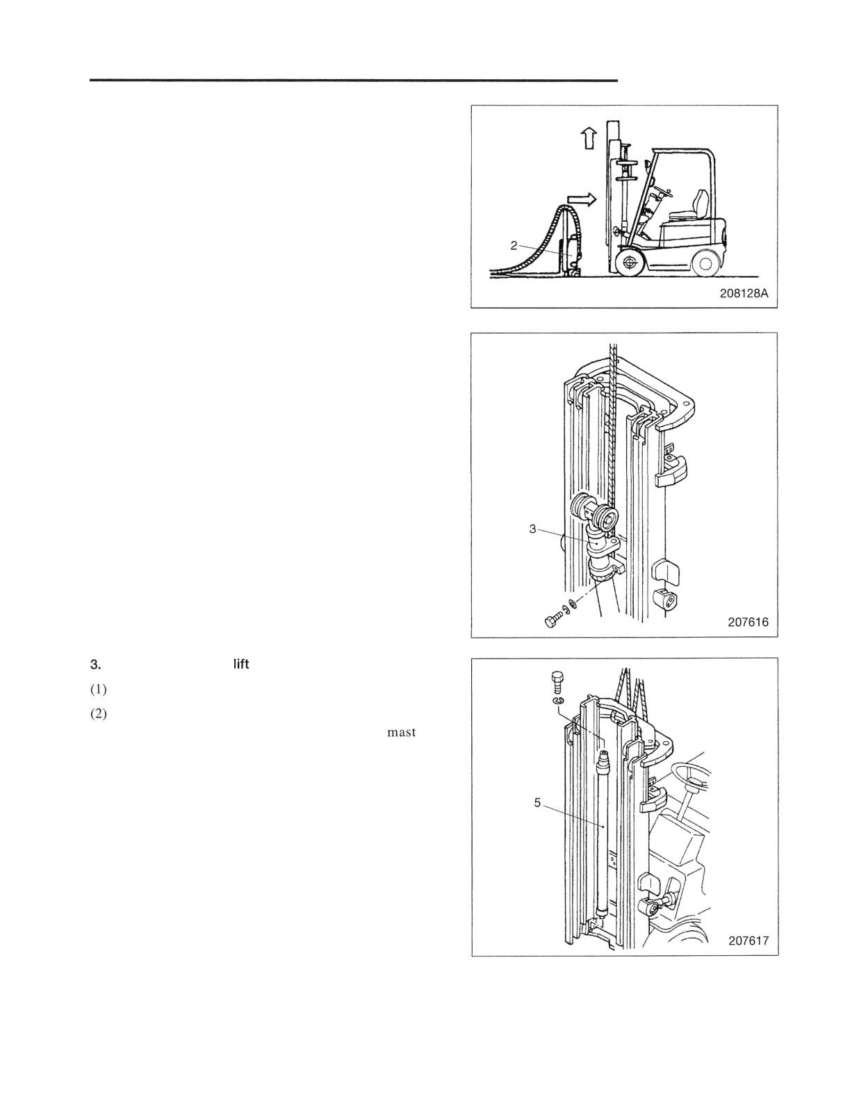
HYDRAULIC SYSTEM
(2) Position the mast upright. Raise the inner mast until
upper rollers 8 of the lift bracket become free. Then,
slowly move the truck in reverse to separate from lift
bracket 2.
2. Removing first lift cylinder
(1) Hitch a sling on the first lift cylinder 3, and suspend it
with a crane. Wind the rope securely to prevent
slipping.
(2) Remove lift cylinder connecting bolts and mounting
bolts, and gently remove the first lift cylinder 3.
Removing second
cylinders 5
Disconnect hoses from the second lift cylinders 5.
Remove stopper bolts at the upper sections of the
second lift cylinders 5, and lift the inner
for
duplex mast or middle mast for triplex mast
approximately 55 cm (21.67 in.) using slings.
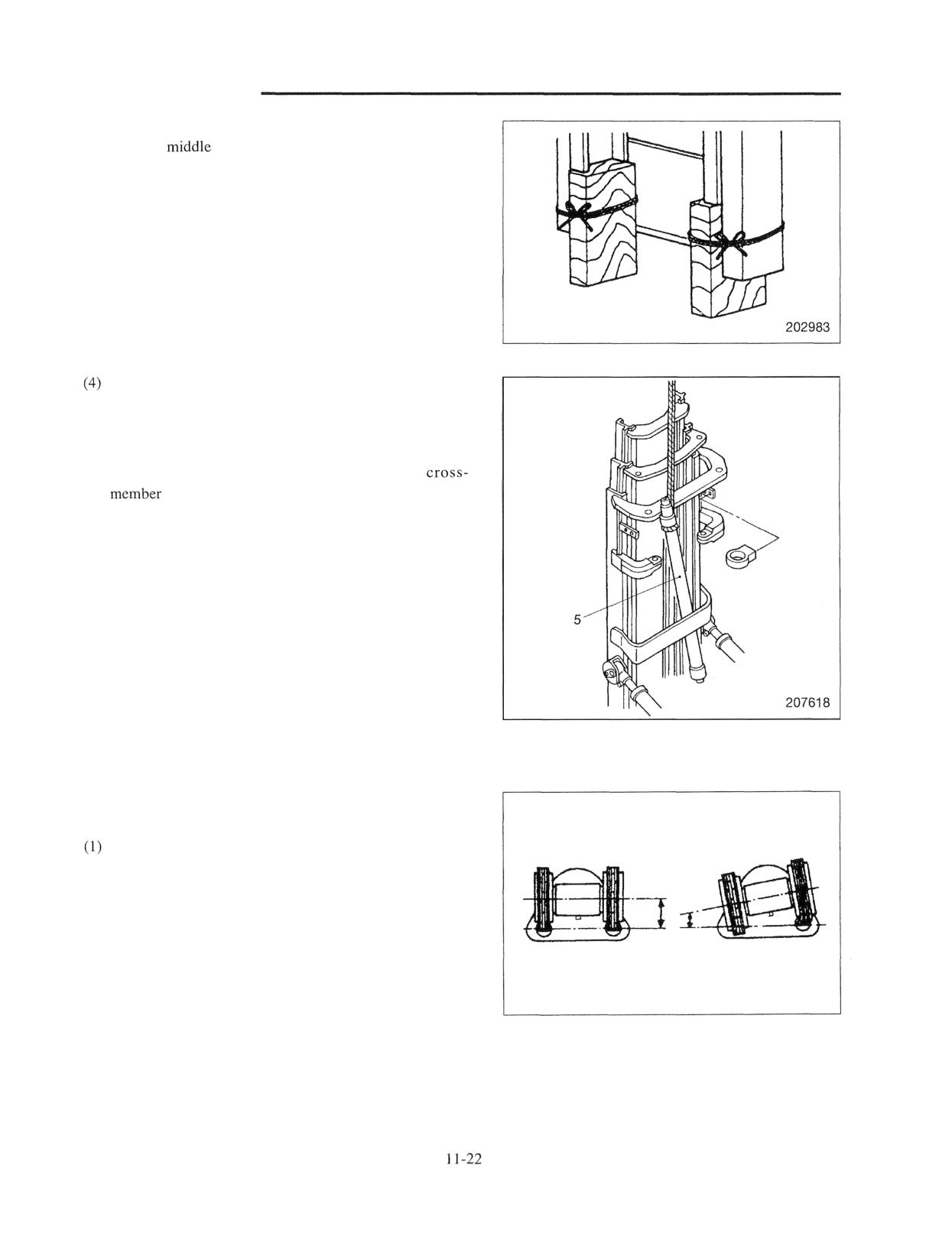
HYDRAULIC SYSTEM
(3) Place wood blocks under the inner mast (for duplex
mast) or
mast (for triplex mast).
Make sure the right and left wood blocks are the same
in height.
Hitch a sling to second lift cylinder 5 behind the mast,
remove cylinder clamp retaining bolts, and gently
remove second lift cylinder 5.
Wind the sling securely to the cylinder. The cylinder
cannot be lifted straight up since the mast
is located above the cylinder, Tilt the cylinder
and move it away from the cross-member to remove.
Be careful not have the hands caught between the
cylinder and mast.
Installation
To reinstall, follow the removal sequence in reverse, and do
the following steps:
Install chain wheel support assembly 4 parallel to a
line connecting the centers of chain anchor bolt holes
on first lift cylinder 3 to prevent chains from twisting.
(2) Adjust the chain tensions.
(Refer to "Chain Tension Inspection" on page 12-33.)
(3) Extend and retract the lift cylinders several times under
Good
Bad
no load condition to bleed air out of the cylinder
207638
circuits and to make sure that the cylinders move
smoothly.
(4) After proper operation is confirmed, check the oil
level.
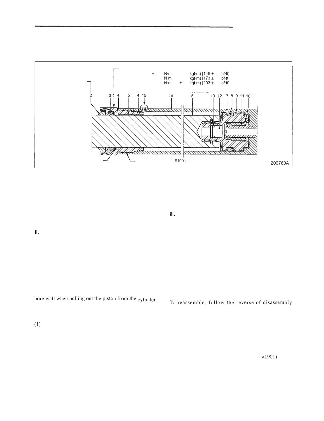
HYDRAULIC SYSTEM
Disassembly and Reassembly
1. Second cylinder for simplex mast and triplex mast
Disassembly
1
Tightening torque
1 ton class: 196
45.1
(20 1: 4.6
33
(M49 x 1.5)
2 ton class: 235 153.9
(24 1: 5.5
40
(M54 x 1.5)
Apply liquid packing to
3 ton class: 275 161.8
(28
6.3
46
(M59 x 1.5)
circumference when
pressing in.
Apply grease when assemblina
Seal in grease.
(Adhesion to
I
bushing is acceptable.)
Apply THREEBOND
when screwing in.
I
Sequence
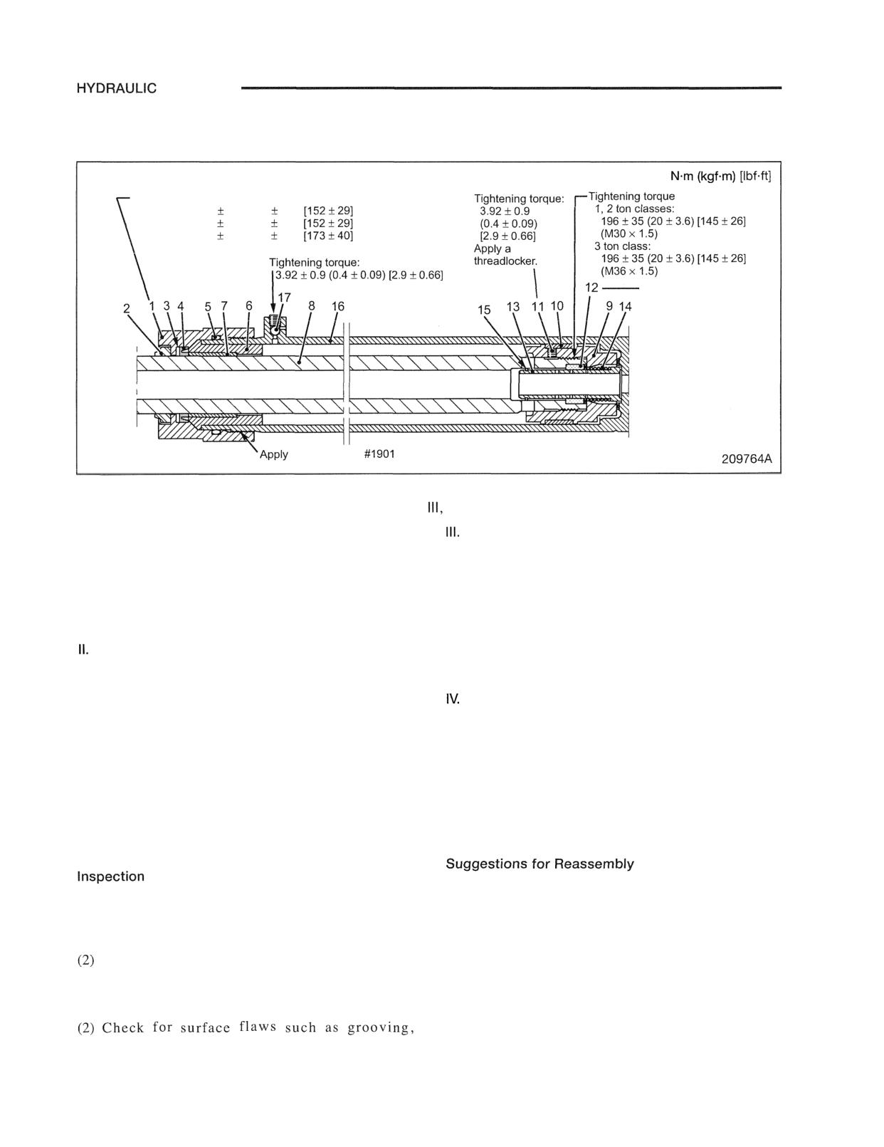
First, disassemble into the three parts of the following I to Ill, and then disassemble the three parts.
I.
Head sub-assembly
10 Snap ring
Consisting of the following parts, 1 thru 5.
11 Cushion bearing
1 Cylinder head
12 Check valve
2 Wiper ring
13 O-ring
3 X-ring
Cylinder tube sub-assembly
4 O-ring
Consisting of the following parts, 1 4 and 1 5.
5 Bushing
14 Cylinder tube assembly
Piston rod sub-assembly
15 Plug
Consisting of the following parts, 6 thru 13
6 Piston rod assembly
Note: The illustration shows a cylinder of the internal
7 Backup ring
drain type without a return pipe. For structure
8 U-ring
of the cylinder with a return pipe, refer to page
9 Bushing
11-7.
Suggestions for Disassembly
3. Rings and packings
Pulling out piston
(1) Check lips for damage, wear, or deterioration.
Be careful not to damage the piston seals and cylinder
Reassembly
Inspection after disassembly
sequence, and do the following steps:
1. Cylinder tube
(1) Clean the disassembled parts with high flash-point
solvent. Blow them dry with compressed air;
Check the bore wall for wear, grooving, scratching
however, this does not apply to rubber parts.
or rusting.
(2) Apply hydraulic oil to the bore surface of cylinder
(2) Check the welds for cracks or other defects.
and also to the piston seal, O-ring, backup ring,
2. Piston rod
buffer ring, packing and dust seal.
(1) Check the rod for deflection.
(3) Apply liquid gasket (THREEBOND
to the
(2) Check for surface flaws such as grooving,
thread.
scratching, rusting or wear.
Tighten to the specified torque using hook wrench.
SYSTEM
2. Second lift cylinder for duplex mast
Disassembly
Unit:
Tightening torque
1 ton class: 206
39.2 (21
4.0)
(M52 x 2)
2 ton class: 206
39.2 (21
4.0)
(M52 x 2)
3 ton class: 235
53.9 (24
5.5)
(M57 x 2)
Be careful of the direction
when installing. Face slit
toward spring side.
THREEBOND
when screwing in.
Sequence
First, disassemble into the three parts of the following I to
and then disassemble the three parts.
I. Holder sub-assembly
Piston rod sub-assembly
Consisting of the following parts, 1 thru 5.
Consisting of the following parts, 8 thru 15.
1 Holder
8 Rod
2 Wiper ring
9 Piston
3 Backup ring
10 Slide ring
4 U-ring
11 Set screw
5 O-ring
12 Check valve
Head sub-assembly
13 Cushion spool
Consisting of the following parts, 6 and 7.
14 Spring
6 Head
15 Snap ring
7 Bushing
Cylinder tube sub-assembly
Consisting of the following parts, 16 and 17
16 Tube assembly
17 Plug
Suggestions for Disassembly
3. Rings, packings and threads
Pulling out piston
(1) Check lips for damage, wear or deterioration.
Be careful not to damage the piston seals and cylinder
(2) Check threads for damage.
bore wall when pulling out the piston from the cylinder.
after disassembly
To reassemble, follow the reverse of disassembly
1. Cylinder tube
sequence, and do the following steps:
(1) Check the bore wall for wear, grooving, scratching
(1) Clean the disassembled parts with high flash-point
or rusting.
solvent. Blow them dry with compressed air;
however, this does not apply to rubber parts.
Check the welds for cracks or other defects.
(2) Apply hydraulic oil to the bore surface of cylinder
2. Piston rod
and also to the piston seal, O-ring, backup ring,
(1) Check the rod for deflection.
buffer ring, packing and dust seal.
(3) Tighten threads of important parts to the specified
scratching, rusting or wear.
torque as per the above illustration.
SYSTEM
3. First lift cylinder for duplex mast and triplex mast
Disassembly
Tightening torque
I ton class: 382
(39
(M75 x 2)
2 ton class: 422
(43
(M80 x 2)
3 ton class: 530
122
(54
12
90
(M95 x 2)
(0.4
r Tightening torque: 3.92
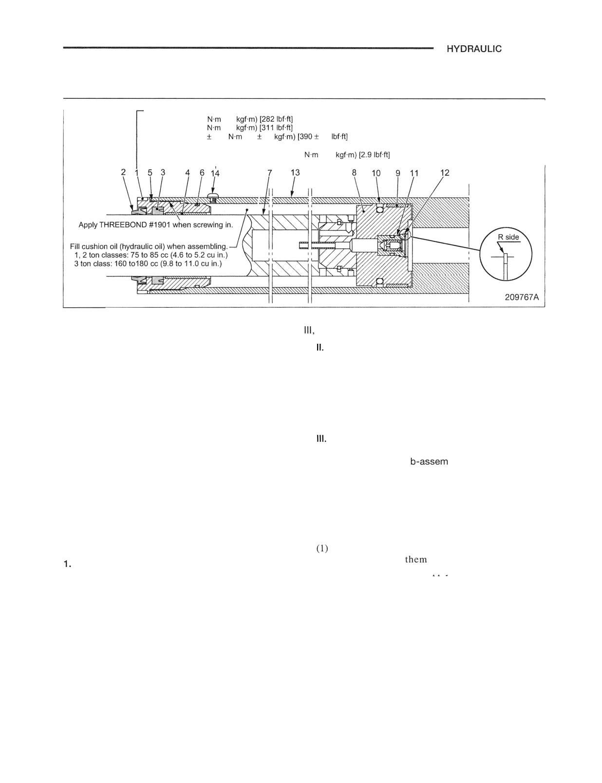
Sequence
First, disassemble into the three parts of the following I to
and then disassemble the three parts.
I. Cylinder head sub-assembly
Piston rod sub-assembly
Consisting of the following parts, 1 thru 6.
Consisting of the following parts, 7 thru 1 2.
1 Cylinder head
7 Rod
2 Wiper ring
8 Piston
3 U-ring
9 Slide ring
4 Bushing
10 Seal ring assembly
5 O-ring
11 Check valve
6 O-ring
12 Snap ring
Cylinder tube sub-assembly
Consisting of the following parts, 1 3 and 14.
13 Cylinder tube su
bly
14 Plug
Suggestions for Disassembly
Suggestions for Reassembly
Be careful not to damage the cylinder bore wall when
To reassemble, follow the reverse of disassembly
pulling out the piston rod from the cylinder.
sequence, and do the following steps:
Inspection after disassembly
Clean the disassembled parts with high flash-point
solvent. Blow
dry with compressed air;
Cylinder tube
however, this does not apply to rubber parts.
(1) Check the bore wall for wear, grooving, scratching
(2) Apply hydraulic oil to the bore surface of cylinder
or rusting.
and also to the piston seal, O-ring, backup ring,
(2) Check the welds for cracks or other defects.
buffer ring, packing and dust seal.
2. Piston rod
(3) Be careful of the direction when installing the snap
(I) Check the rod for deflection.
ring 12 of the check valve.
(2) Check for surface flaws such as grooving,
(4) Fill hydraulic oil as cushion oil in the space
scratching, rusting or wear.
between the tube and rod before reassembling the
cylinder head.
3. Rings, packings and threads
(5) Tighten threads of cylinder head 1 to the specified
(I) Check lips for damage, wear or deterioration.
torque as per the above illustration.
(2) Check threads for damage.
HYDRAULIC SYSTEM
Tilt Cylinder
Removal and Installation
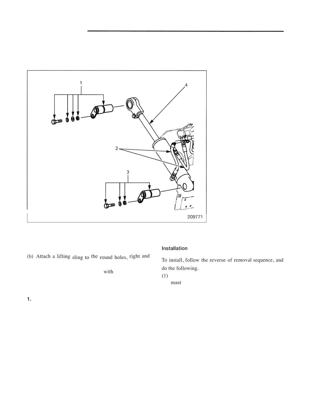
Removal
Sequence
1
Tilt cylinder pin
2
Hoses (2 pcs. per one
cylinder)
3 Tilt cylinder pin
4
Tilt cylinder
Start by:
3. Removing tilt cylinder
(a) Lower the forks to the bottom, and tilt the mast
Remove tilt cylinder pin 3, and remove the cylinder.
fully forward.
left, in the top cross-member of outer mast, and
support the weight of the mast
a hoist.
After installing tilt cylinders, check the balance of
tilting angle. Adjust if necessary. Refer to
Suggestions for Removal
"Tilt Angle Adjustment (all mast models)" on page
12-38.
Retracting piston rod
Remove tilt cylinder pin I , start the engine and retract
the piston rod fully, then stop the engine.
2. Disconnecting hoses
Disconnect hoses 2 from the cylinder at the connectors.
Use a drip pan to catch oil flowing out of the cylinder.
Attach caps to the connectors of the cylinder to protect
the threads of the connectors and to prevent oil from
flowing out of the cylinder when the cylinder is
removed.
HYDRAULIC SYSTEM
Disassembly and Reassembly
Disassembly
Tightening torque
1 ton class: 265
29
(27
3.0
95
21
2 ton class: 314
31
(32
3.2
23
3 ton class: 373
37
(38
3.7
27
After tightening nuts,
crimp two locations.
Tightening torque
1 ton class: 127
9.8
(13
[94
7.2
Tightening torque:
2 ton class: 235
19.6
(24
2.0
14.5
153 to 182
3 ton class: 392
25
(40
2.5
18.4
(16 to 19
13 to 134
209772
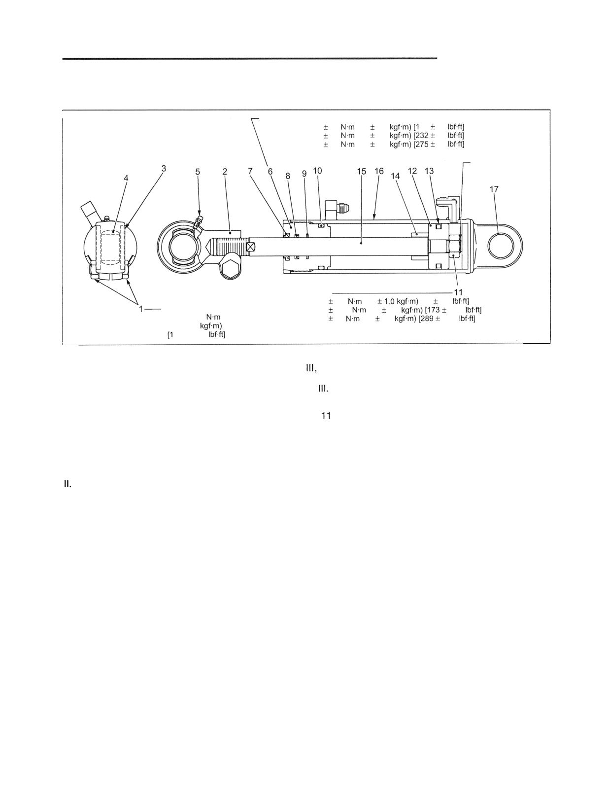
Sequence
First, disassemble into the three parts of the following I to
and then disassemble the three parts.
I. Tilt socket sub-assembly
Piston rod sub-assembly
Consisting of the following parts, 1 thru 5.
Consisting of the following parts, 11 thru 15.
1 Bolt, Nut
Nut
2 Tilt socket
12 Piston
3 Seal
13 Piston seal
4 Bearing
14 Spacer
5 Grease nipple
15 Rod
Guide bushing sub-assembly
IV. Cylinder sub-assembly
Consisting of the following parts, 6 thru 1 0,
Consisting of the following parts, 16 and 17.
6 Guide bushing
16 Cylinder assembly
7 Dust seal
17 Bushing
8 Packing
9 Buffer ring
10 O-ring
Note: (a) Before disassembly, make a record of the
dimension from the holder edge to the socket
edge when the rod is fully pushed in. The
record will be helpful for reassembly.
(b) Do not disassemble the tilt socket bearing
and cylinder tube bushing unless
abnormality, is found on inspection.
(c) DO not disassemble the piston and nuts
unless abnormality, is found on inspection.
HYDRAULIC SYSTEM
Suggestions for Disassembly
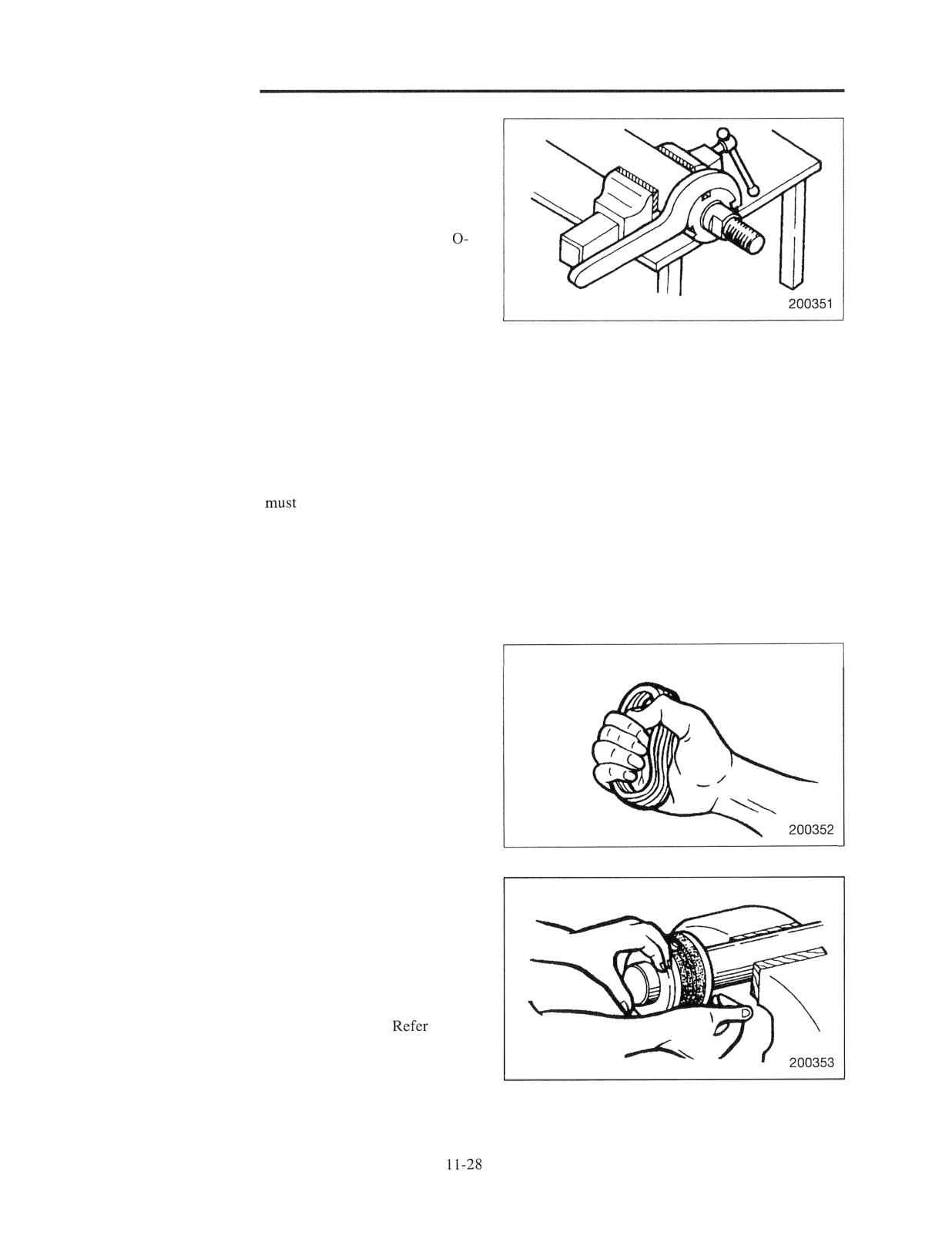
Removing bushing
(I) Wrap the cylinder with a rag, and clamp it in a vise.
Using a wrench, remove the bushing from the cylinder.
(2) When removing the bushing from the piston rod, be
careful not to rub damage the buffer ring, packing,
ring against the threads of the piston rod.
Inspection after disassembly
1. Cylinder tube
(I) Check the bore wall for wear, grooving, scratch marks
and rusting.
(2) Check the welds for cracks.
2. Piston rod
Check for surface flaws such as grooving, scratch marks,
rusting and wear. The rod
be replaced if its threads
show a sign of stripping or any other damage.
3. Rings and packing
(1) Check each ring and packing for damage or distortion.
(2) Also check for deterioration due to aging.
Precautions for reassembly of lift and tilt cylinders
(I) Carefully clean all parts to remove any foreign particle.
(2) Reassemble the cylinder in the reverse sequence of the
disassembling, apply hydraulic oil to the bore wall of
the cylinder tube, and also to sealing parts - O-rings,
piston seals, dust seals and packings. Pay attention to
the correct part arrangement.
(3) When clamping the cylinder tube in the vise , be
careful not to distort the tube.
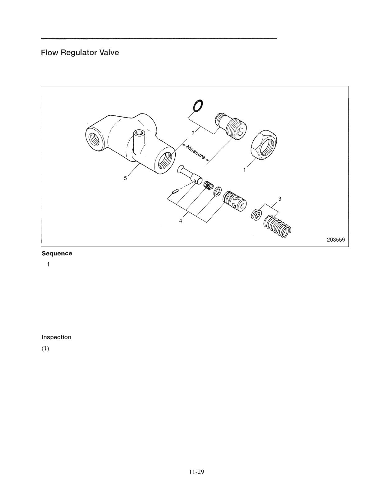
(4) Install the piston seal as follow:
(a) Before fitting the piston seal, squeeze it by hand
five or six times to soften it.
(b) Hold the piston in a vise, taking care not to damage
any part of the piston. Apply a thin coat of
hydraulic oil to the seal. Fit a portion of the seal to
the groove, and push the other portion into the
groove as shown.
(5) Tighten the thread to the specified torque.
to the
previous page for the torque.
HYDRAULIC SYSTEM
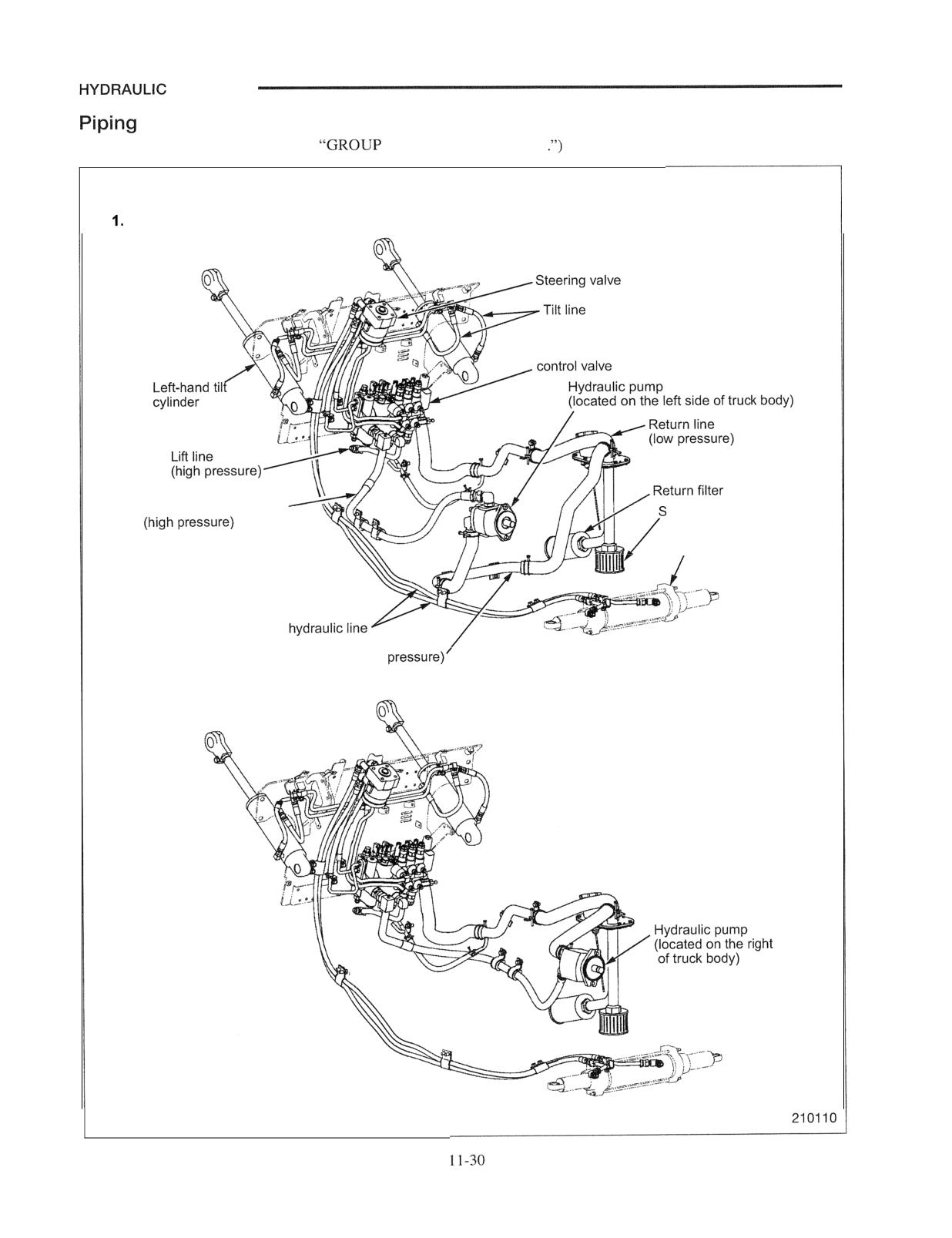
(Installed on trucks with FC control valve only)
Disassembly and Reassembly
Disassembly
Lock nut
4 Piston, Pin, Washer, Spring, Valve
2 Plug, O-ring
5 Valve body
3 Spring, Shims
Note: Before disassembling, measure the protrusion of the
plug. On assembling, adjust the protrusion as
before.
Check the spring for fatigue.
(2) Check the sliding and contact surfaces of valve and
piston for damage.
(3) Check the sliding surfaces of piston and valve body for
damage.
Note: Replace the flow regulator valve as an assembly if
any part is defective.
Reassembly
To reassemble, follow the reverse of disassembly sequence.
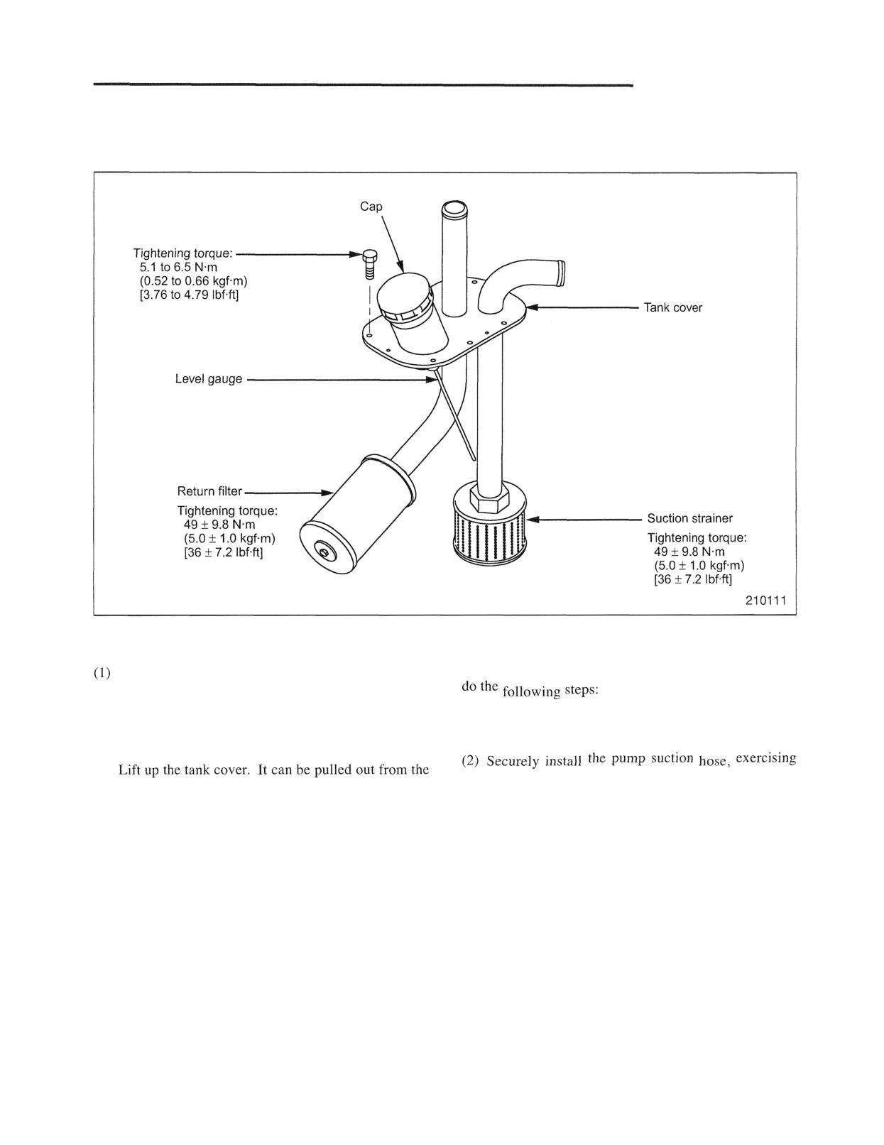
SYSTEM
(For piping around the mast, refer to
12 MAST AND FORKS
Piping for diesel-engine truck
Pump discharge oil line
uction strainer
Steering cylinder
Steering
Pump suction line (low
2. Piping for gasoline-engine truck
side
HYDRAULIC SYSTEM
Suction Strainer and Return Filter
Removal and Installation
Removal
Installation
Remove the suction hose from the pump.
To install, follow the reverse of removal sequence, and
(2) Remove the hose of the return line from the control
valve.
(1) Tighten the strainer and filter to the specified
torque.
(3) Remove all of tank cover mounting bolts.
(4)
care to avoid sucking in air.
tank as shown in the above illustration.
(5) Remove the suction strainer and return filter.
Inspection
(1) Clean the suction strainer.
(2) The return filter is a periodic replacement part.
Replace it when changing oil. In case of a new
truck or carrying out an overhaul, replace it after
the first month.
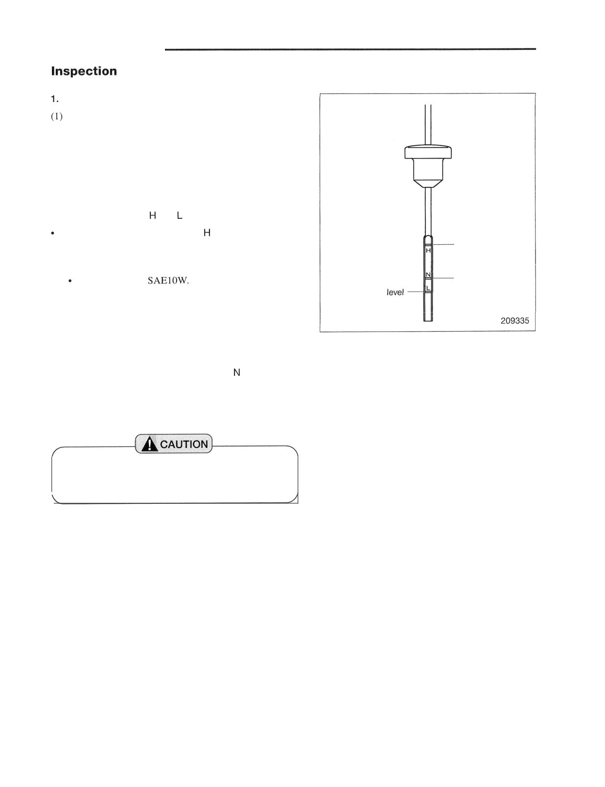
HYDRAULIC SYSTEM
and Adjustment
Hydraulic tank
Daily check of oil
Check oil for level, dirt and white turbidity (entry of air,
mixing of water).
(2) Adequate oil level during daily check
Check the oil level with the mast lowered.
Simplex mast: Between N and L level
Triplex mast: Between and level
The oil lcvcl must not exceed the level with any mast
and attachment when they are lowered.
Maximum level for
triplex mast
(3) Method of filling hydraulic tank with oil
Maximum level for
Use hydraulic oil
simplex mast
Minimum
(a) Fill the hydraulic tank with oil with the mast
lowered.
(b) Repeat ascent and descent of the mast a few times,
and then lower the mast.
(c) Check the oil level with a level gauge. The
maximum acceptable level is the level for the
simplex mast and the H level for the triplex mast.
If the level is low, replenish oil.
The oil level in the tank must not exceed the H
level with any combination of the mast and
attachment when the mast is lowered.
(4) Inspection of suction strainer
Check the suction strainer for damage and clogging. Clean
it if it is dirty.
(5) Inspection of return filter
Check the return filter for damage. As this part needs
periodic replacement, replace it when the replacement
interval is reached.
Refer to page 11-31 "Removal and Installation of Suction
Strainer and Return Filter."
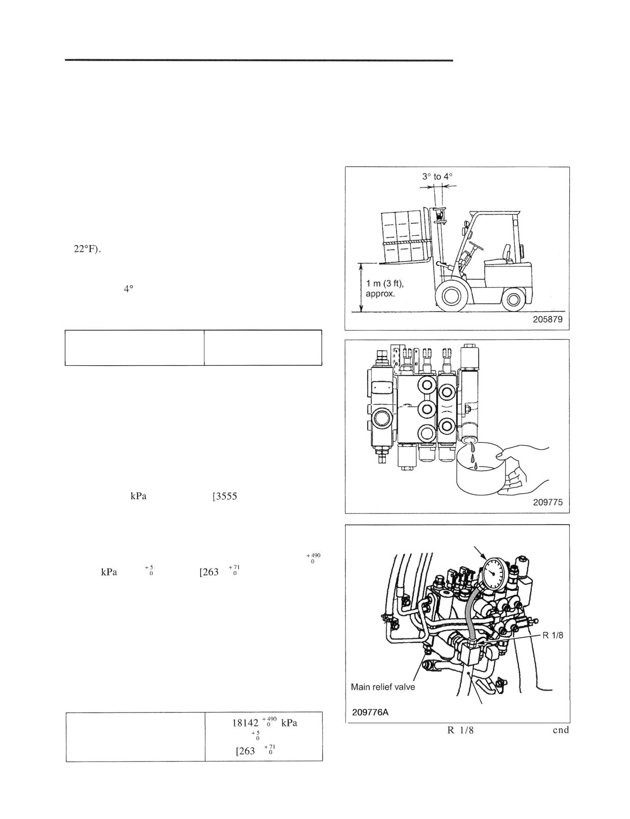
HYDRAULIC SYSTEM
2. Control Valve
(1) External leakage
(a) Check for oil leaks from the joint between adjacent
valve housings sealed by O-ring.
(b) Check for oil leaks from the screw connections.
(2) Internal leakage
It is not practical to check the control valve alone for
internal leakage. How to check the control valve in place
(under normal operating conditions) will be described.
The internal leakage to be checked includes leakages
occurring at the lift spool, tilt spool, tilt lock valve and
check valves at the oil temperature of approximately 50°C
(1
(a) Pick up a load equal to the rated capacity, and lift it
approximately 1 m (3 ft) high. Tilt the mast about
3" to forward, and stop the engine.
(b) Quickly disconnect the oil return hose, and start
collecting the oil coming out of this hose as shown.
Amount of oil collected for
20 cc (1.2 cu in.)
15 minutes
or less
(c) If the lift cylinders or tilt cylinders drift (the mast
tilts forward or the fork lowers) excessively in
spite of that the amount of oil collected for 15
minutes is less than 20 cc (1.2 cu in.), measure the
internal leakage of each cylinder.
(The
measurement is the assembly standard and not the
service limit.)
(3) Main Relief Valve
(a) Install a pressure gauge capable of measuring up to
25000
(250 kgf/cm2)
psi] to the delivery
hose connector. Use the gauge, connectors and
hose used for testing the gear pump.
(b) Start the engine and run it at the maximum speed.
Pressure gauge \
Move the tilt control lever to the backward tilt
position. If the pressure is relieved at 18142
(185
kgf/cm2)
1
psi] when the
tilt cylinders reach the end of their stroke, the main
relief valve setting is correct.
(c) If the setting is incorrect, loosen the lock nut of
adjusting screw and, while observing the pressure
gauge reading, slowly rotate the adjusting screw
until the gauge indicates the prescribed set value.
(d) While holding the adjusting screw, tighten the lock
nut to secure the adjusting screw.
(e) After securing the adjusting screw, recheck the
setting.
Pump delivery hose
Remove the plug of
from the metal
Main relief valve setting
(185
kgf/cm2)
fittings of the pump delivery hose and install a
1
psi]
pressure gauge.
11-33
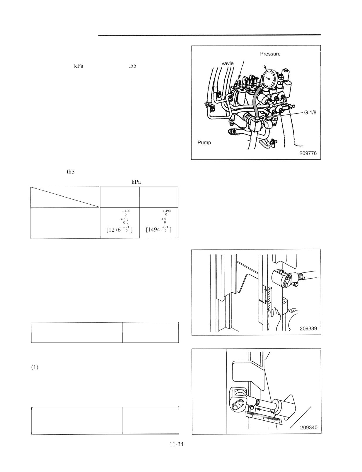
HYDRAULIC SYSTEM
(4) Adjustment of steering system relief valve
Steering system
gauge
(a) Attach a pressure gauge capable of measuring up
relief
\
to 25000
(250 kgf/cm2) [35
psi] to the pump
delivery hose connector (illustration on the right).
(b) Set the control lever to neutral.
(c) Start the engine and run it at the medium speed.
Turn the steering wheel to the extreme right or to
left to relieve oil in the steering system. The relief
pressure must be within the range in the table
below.
(d) If the relief pressure is outside the range, remove
delivery
the cap and turn the adjusting screw for
hose
adjustment.
(e) If the pressure is correct, tighten the lock nut and
check
relief pressure again.
Unit:
(kgf/cm2) [psi]
Truck Model
1 ton
2,3 ton
class
classes
Item
8800
10300
Set pressure of steering
(90
(105
)
system relief valve
3. Descent test
(1) Pick up a load equal to the rated capacity, place the
mast to a vertical position, lift the fork 1 to 1.5 m (3.3
to 4.9 ft), and stop the engine.
(2) Mark a reference line on the mast, and measure the
descent (retraction of the piston rods) for 15 minutes.
Divide the measured value by two to calculate the
retraction of piston rods.
Descent (retraction of piston rods)
50 mm (2 in.)
with rated load for 15 minutes
maximum
4. Forward tilt test
Pick up a load equal to the rated capacity, place the
mast to a vertical position, lift the fork about 50 cm (20
in.), and stop the engine.
(2) Measure the extension of tilt cylinder piston rod for 15
minutes.
Amount of forward tilt (extension
20 mm (0.8 in.)
of piston rods) with rated load for
maximum
15 minutes
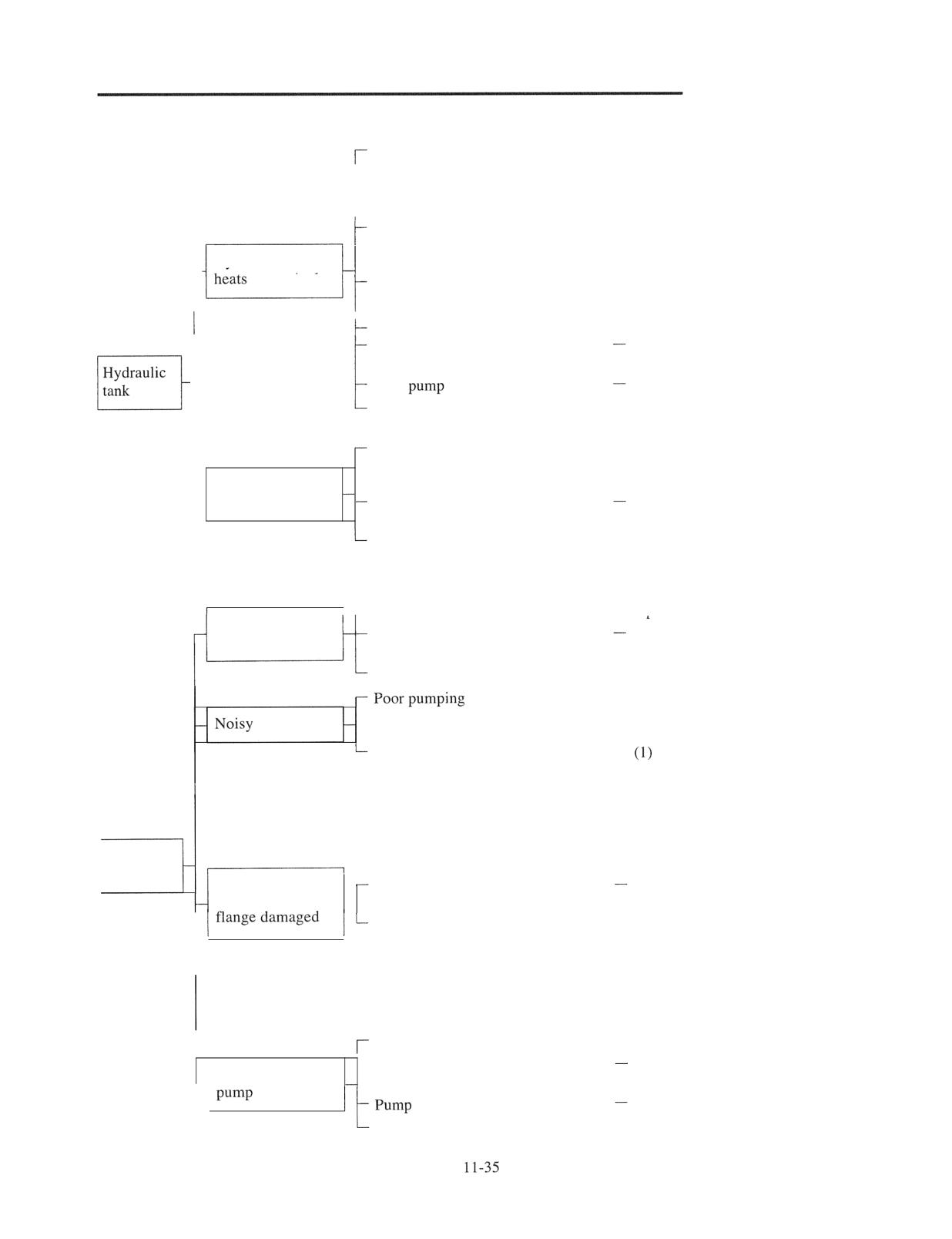
HYDRAULIC SYSTEM
Troubleshooting
Not enough oil in hydraulic tank
-
Refill.
Oil viscosity improper
-
Change upon referring to "Fuel
and Lubricant Specifications" on
page 13-13.
t
Overload
-
Check working conditions and, if
over-loaded, urge the operator to
Hydraulic tank
stay within the load limit.
Local overheating of oil line due to
-
Clean oil line.
a large restriction to flow
Relief valve adjustment improper
-
Readjust pressure setting.
Pressure drop due to fatigued or
Disassemble or replace and
broken springs
readjust pressure.
Hydraulic
Gear
worn
Replace pump.
-
Outlet pipe or tube flattened, or
Repair or replace.
restriction to flow
Shortage of oil due to a natural loss
-
Replenish oil upon referring to
"Fuel and Lubricant Specifications"
on page 13-13.
Cylinders move
too slow
Oil leakage due to damaged oil line
Repair or replace.
and seals
Oil viscosity too high
-
Replenish oil upon referring to
"Fuel and Lubricant Specifications"
on page 13-13.
Gear pump does not pump oil
-
Check pump and piping; repair or
,
r
rewlace.
Cylinders move
Oil leakage from oil line
Check oil for level and condition;
too slow
add or change oil.
Gear pump internally leaking
-
Replace pump.
- Replenish oil upon referring to
"Fuel and Lubricant Specifications"
on page 13-13.
Cavitation
-
Check suction pipe for any flat
portion or loose connection;
retighten or replace.
(2) Check shaft oil seal for
airtightness; replace pump.
(3) Check pump body for any
Gear pump
outside interference; repair.
Pump case, drive
Pressure too high
Replace pump. (Check to see if
gear or pump port
-
relief valve setting is correct.)
Distortion or damage due to external -
Replace pump.
strain or stress
(1) Check to see if return line is
blocked or restricted.
(2) Check to see if pipe
connections have been
externally strained or stressed.
Oil leakage past oil seal
- Replace shaft seal.
I
- Oil leakage past sliding surfaces of
Replace whole pump assembly.
Oil leakage from
drive shaft
securing bolts loose
Retighten. Replace if needed.
Degraded performance of sealing
-
Replace gasket.
inside pump
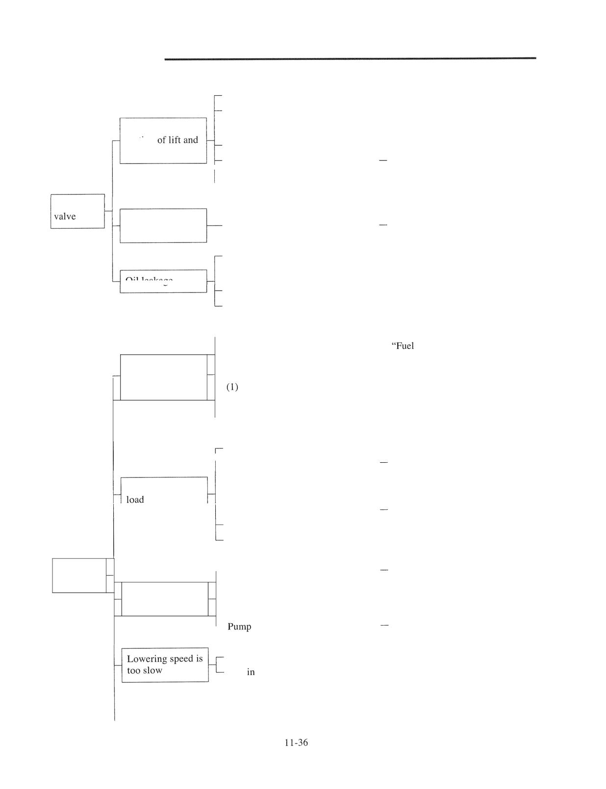
HYDRAULIC SYSTEM
Relief valve set pressure lowered
-
Readjust pressure.
Relief valve piston seizure
- Wash piston and check to see if it
moves smoothly; or replace whole
Slow or no
relief valve assembly.
O-ring on relief valve body damaged-
Replace O-ring.
tilt cylinders
Control lever installed loose,
Readjust.
resulting in not enough spool stroke
Abnormal oil temperature rise
-
Check control valve spool for
misalignment; repair or replace.
Control
Load descends or
Control valve internally leaking
Replace a leaky block assembly.
mast tilts forward
Oil leakage from spool ring cap
-
Replace O-ring; check spool for
flaws and if any, repair or replace a
leaky block assembly.
Oil leakage
Loose plug
-
Retighten plug.
O-ring damaged
-
Replace O-ring.
-
Not enough oil in hydraulic tank
-
Replenish oil upon referring to
and Lubricant Specifications"
on page 13-13.
Mast will not lift
- Relief valve out of order, because of:
or tilt forward or
backward
Seized main valve
-
Replace.
(2) Broken valve spring
- Replace.
-
Gear pump defective
- Replace.
Relief valve out of order, because of:
(1) Too low a relief valve setting
Readjust pressure.
(2) Defective plunger or poppet seat - Replace.
Will not lift rated
(3) Fatigued spring
-
Replace.
(4) Damaged O-ring in valve case
Replace.
Gear pump defective
-
Replace.
Piston seals worn or damaged
-
Replace.
Lift and tilt
- Engine speed too low
Adjust engine.
cylinders
-
Control lever installed loose,
- Adjust.
Lifting speed is
resulting in not enough spool stroke
too slow
-
Tank strainer clogged
-
Clean or replace.
-
not delivering enough oil
Repair or replace.
Sleeve seized in flow regulator valve- Repair.
Dirt flow regulator valve,
- Clean, repair system and replace
abnormal resistance to flow due to
defective hose.
flattened hose or local clogging
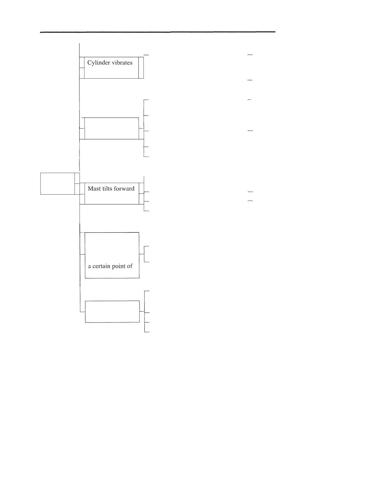
HYDRAULIC SYSTEM
Piston rod distorted
Repair or replace.
- Air trapped in oil circuit
- Bleed air by operating cylinder
when actuated
through full stroke.
- Not enough oil in hydraulic tank
Refill.
Control valve spool internally
- Replace a leaky block assembly.
leaking
Sliding (inside) surface of cylinder
- Repair or replace.
tube slightly grooved
Load descends
fast
Sliding (inside) surface of cylinder
Replace cylinder assembly.
tube badly grooved
Piston seals broken or distorted
-
Replace seal kit.
Oil leakage from piping
-
Repair or replace.
- Control valve spool internally
- Replace a leaky block assembly
Lift and tilt
leaking
cylinders
Foreign particles lodged in packing
Replace packing.
(drift)
Piston seals damaged
Replace seals.
Other abnormal distortion, oil
-
Repair or replace.
leakage from piping
Lift cylinders
descend or tilt
Sliding surface of cylinder tube
- Repair or replace.
cylinders tilt
badly grooved or rusted at one point
forward (drift) at
Cylinder tube distorted
stroke
-
Replace.
Foreign particles lodged between
-
Replace.
sealing members such as oil seals and
dust seals
Oil leakage at
bushing
Oil seals and dust seals grooved
-
Replace.
O-rings damaged
-
Replace O-rings.
Cylinder abnormally distorted
- Repair or replace.
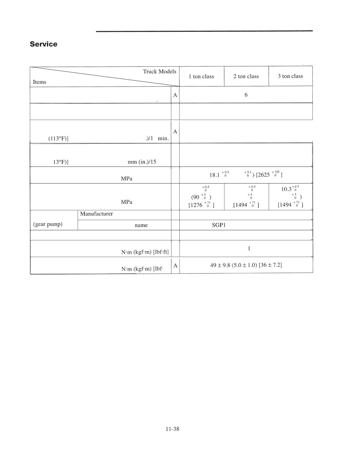
HYDRAULIC SYSTEM
Data
A: Standard value
Unit: mm (in.)
Forward tilt angle (standard truck with simplex mast)
degrees
Backward tilt angle (standard truck with simplex mast)
A
12
degrees
Lift cylinder descent amount (at rated load)
[Retracted length of rod, oil temperature at
50 (2) or less
45°C
mm (in
5
-
-
Tilt cylinder forward tilt amount (at rated load)
[Extended length of rod, oil temperature at
A
20 (0.8) or less
45°C (1
min.
Main relief valve setting
A
(185
(kgf/cm2) [psi]
8.8
10.3
Steering system relief valve setting
A
(105
)
(105
(kgf/cm2) [psi]
SHIMADZU CORPORATION
Hydraulic pump
Manufacturer's model
type single gear pump
Manufacturer of control valves
SHIMADZU CORPORATION
Tightening torque of return filter
A
49 1 9.8 (5.0 1 .O) [36 1 7.21
Tightening torque of suction strainer
ft]
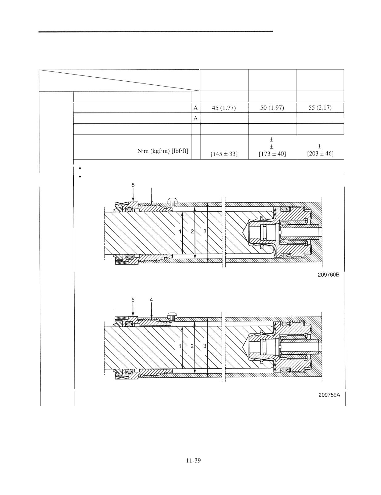
HYDRAULIC SYSTEM
A: Standard value
Unit: mm (in.)
Truck Models
1 ton class
2 ton class
3 ton class
Items
Rod outside diameter 1
A
35 (1.38)
40 (1.57)
45 (1.77)
Cylinder inside diameter 2
Cylinder outside diameter 3
52 (2.05)
57 (2.24)
63 (2.48)
Thread size of cylinder head 4
A
M49
M54
M59
1961 45.1
235
53.9
275 161.8
Tightening torque of cylinder head 5
A
(2014.6)
(24
5.5)
(28
6.3)
Simplex mast with raised height of 3.4 m (11.2 ft) or less
All triplex masts
4
Second
cylinder for
simplex
mast and
triplex mast
Simplex mast with raised height of 3.5 m (11.5 ft) or higher
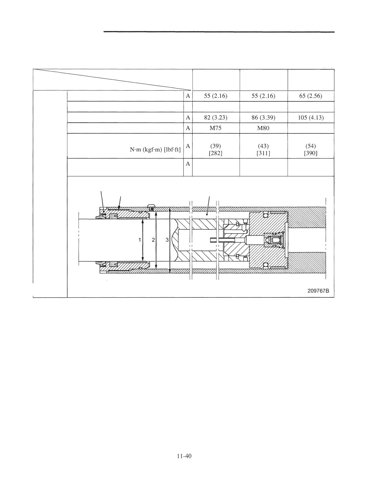
HYDRAULIC SYSTEM
A: Standard value
Unit: mm (in.)
Truck Models
1 ton class
2 ton class
3 ton class
Items
Rod outside diameter 1
Cylinder inside diameter 2
A
70 (2.76)
75 (2.95)
90 (3.54)
Cylinder outside diameter 3
Thread size of cylinder head 4
M95
382
422
530
Tightening torque of cylinder head 5
Sealed-in amount of cushion oil
75 to 85
75 to 85
160 to 180
cc (cu in.)
(4.6 to 5.2)
(4.6 to 5.2)
(9.8 to 11.O)
First
cylinder for
5
4
6
duplex
I
I
mast and
triplex mast
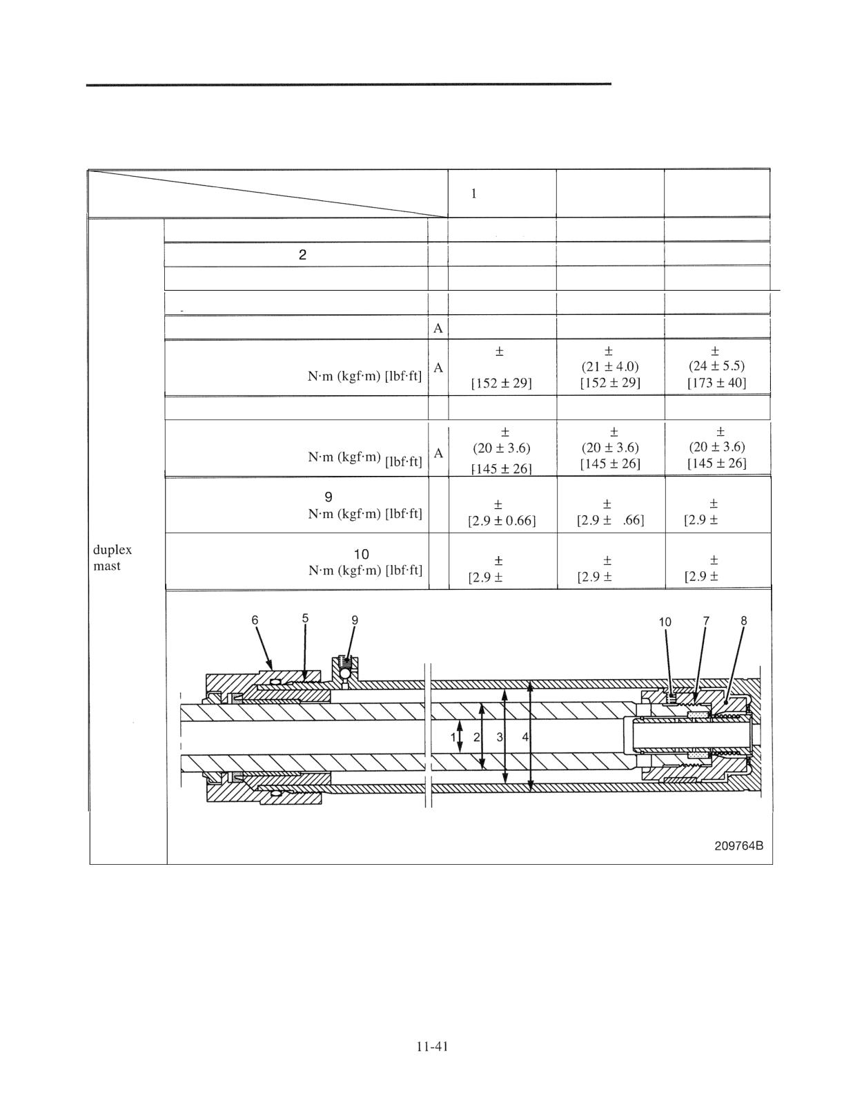
HYDRAULIC SYSTEM
A:
Standard value
Unit: mm (in.)
Truck Models
ton class
2 ton class
3 ton class
Items
Rod inside diameter 1
A
16 (0.63)
16 (0.63)
20 (0.79)
Rod outside diameter
A
32 (1.26)
35 (1.38)
40 (1.57)
Cylinder inside diameter 3
A
45 (1.77)
45 (1.77)
50 (1.97)
Cylinder outside diameter 4
A
53 (2.09)
53 (2.09)
60 (2.36)
Thread size of holder 5
M52
M52
M57
206
39.2
206
39.2
235
53.9
Tightening torque of holder 6
(2140)
Thread size of piston 7
A
M30
M33
M36
196
35
196
35
196
35
Tightening torque of piston 8
3.92
3.92
3.92
Tightening torque of plug
A
(0.4
0.09)
(0.4
0.09)
(0.4
0.09)
Second
0
0.661
cylinder for
3.92
3.92
3.92
Tightening torque of set screw
A
(0.4
0.09)
(0.4
0.09)
(0.4
0.09)
0.661
0.661
0.661
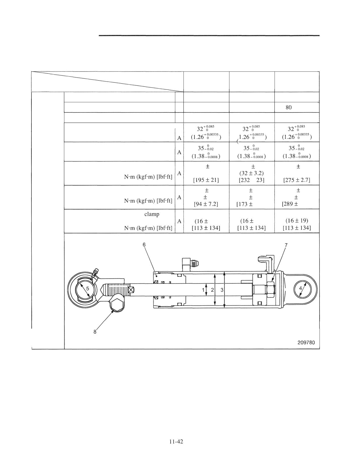
HYDRAULIC SYSTEM
A: Standard value
Unit: mm (in.)
Truck Models
1 ton class
2 ton class
3 ton class
Items
Rod outside diameter 1
A
25 (0.98)
30 (1.18)
35 (1.38)
Cylinder inside diameter 2
A
63 (2.48)
70 (2.76)
(3.15)
Cylinder outside diameter 3
A
73 (2.87)
82 (3.23)
93 (3.66)
Bushing inside diameter on head side 4
Bushing outside diameter on rod side 5
265
29
314
31
373
37
Tightening torque of guide bushing 6
(2713.0)
(38 13.7)
1
127
9.8
235
19.6
392
25
Tightening torque of nut 7
(13
1.0)
(24
2.0)
(40
2.5)
14.51
18.41
Tightening torque of tilt socket
153 to 182
153 to 182
153 to 182
Tilt
bolt 8
19)
19)
cylinder
HYDRAULIC SYSTEM
Control Valve
Structure and Operation
I I
Control Valve
I I
44
Hydraulic Circuit Diagram of Hydraulic Control Valve
I I
. 45
Cover Section
11
46
Lift Valve
11.
48
Tilt Valve
11 . 50
Unloader Valve
11
52
Removal and Installation
of Control Valve
Removal and
11 - 53
Disassembly and Reassembly
-
Valve of
Cover Section
11 - 54
Combination Section
11 - 55
End Cover Section
I1 - 57
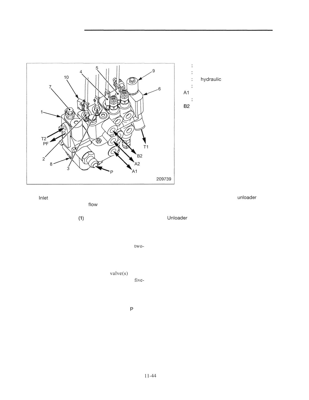
HYDRAULIC SYSTEM
Structure and Operation
Control Valve
P Pressure oil inflow port from pump
PF To steering control valve
Tl To
tank (return line)
T2 Return from steering control valve
: To lift cylinder
A2 To tilt cylinder rod end
: To tilt cylinder head end
Main valves
1
cover section (with built-in priority valve)
6 End cover section (with built-in
valve)
2 Lift valve (with built-in
regulator valve)
7 Steering system relief valve
3 Tilt valve
8 Main relief valve
4 Attachment valve
9
valve (with solenoid)
5 Attachment valve (2)
10 Lift lowering limit switch (if equipped)
The above illustration shows an external view of the
Lift valve 2 is a direction control valve which feeds and
four-valve type control valve. Any one of the
returns pressure oil to and from the lift cylinder. The
valve to five-valve type valves is installed on a truck
lift valve also has a built-in flow regulator valve.
depending on forklift specifications. The most basic
Tilt valve 3 feeds and returns pressure oil to and from
valve configuration is a two-valve type, combination of
the tilt cylinder which tilts the mast forward or
the lift and tilt. Adding attachment
to this
backward. The tilt lock valve is assembled in the main
combination is three-valve type, four-valve type or
spool to ensure safety when the mast is tilted forward.
valve type valve.
Attachment valves 4 and 5 are direction control valves
Inlet cover section 1 has a built-in priority valve. This
which feed pressure oil to actuators of the attachments.
valve is a flow divider valve which feeds a certain
End cover section 6 is provided with unloader valve 9.
amount of the total inflow volume from the port
This valve is linked with the seat switch, and is a
preferentially to the steering system and the extra flow
solenoid valve which closes the parallel feeder (high-
volume to the cargo-handling valve. In addition, the
pressure circuit) to hold pressure oil only when the seat
inlet cover section is provided with main relief valve 8
switch is ON.
and steering relief valve 7. Each of these valves limits
the maximum pressure to protect the system.
Lift valve 2 and tilt valve 3 are assembled adjacent to
the combination section.
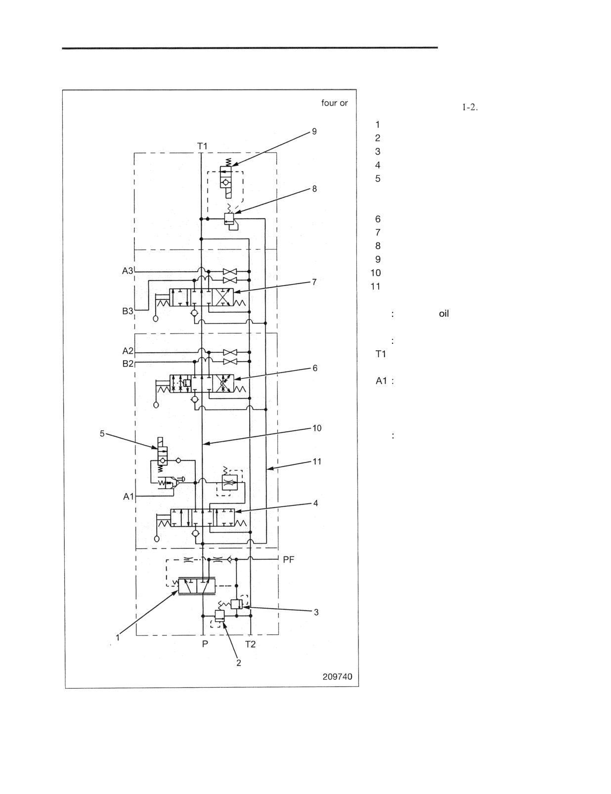
HYDRAULIC SYSTEM
Hydraulic Circuit Diagram of Hydraulic Control Valve
For the entire diagram of the hydraulic
This diagram is for the three-valve type control valve. For the
system, refer to page 1
five-valve type control valve, the attachment valve 7 is added.
Priority valve
Main relief valve
Steering system relief valve
Lift valve
Solenoid valve (operates in
conjunction with lift lowering
switch)
Tilt valve
Attachment valve
Unloader valve
Solenoid for unloader valve
Center bypass port
Parallel feeder
P Supplied from pump
PF : To steering valve
T2 Return from steering valve
: To hydraulic tank
To lift cylinder
A2 : To tilt cylinder rod end
B2 : To tilt cylinder head end
A3 : To actuator for attachment valve
B3 To actuator for attachment valve
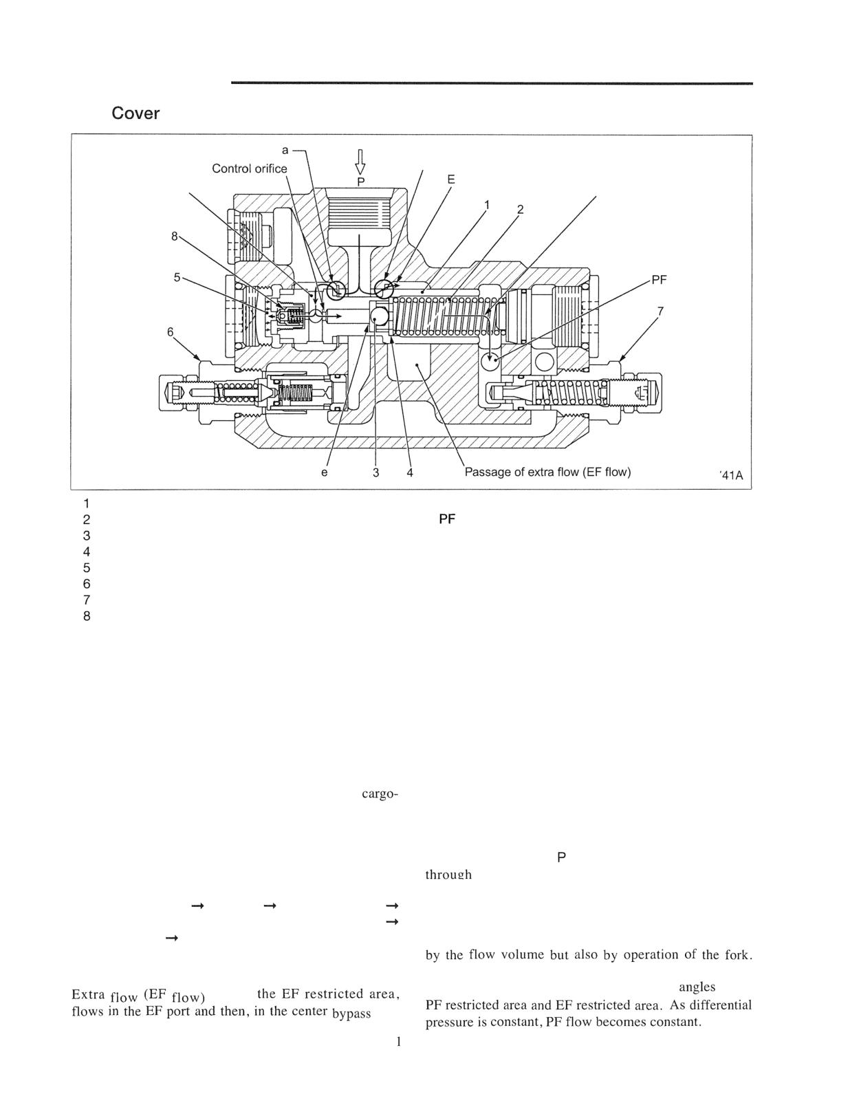
HYDRAULIC SYSTEM
Inlet
Section
PF restricted are
EF restricted area
xtra flow (EF flow)
Hole A
Priority flow (PF flow)
Ball check seat surfac
2097
Priority valve spool
P
: From hydraulic pump (pump port)
Spring
: To steering valve (priority port)
Ball check
EF : To cargo-handling valve (extra port)
Ball retainer
Damper chamber
Main relief valve
Steering system relief valve (PF relief valve)
Valve
The inlet section of control valve consists of main relief
When the flow volume flowing in the port P from the
valve 6, which limits the maximum pressure of the
pump increases, PF flow passing the control orifice is
hydraulic system, the priority valve, which feeds
going to increase. Then, differential pressure before and
pressure oil preferentially to the steering system, and
after the control orifice becomes greater.
steering system relief valve7, which limits the
On the left edge face of valve spool 1 acts hydraulic
maximum pressure of the supplied pressure oil.
pressure before the control orifice, namely pump
The priority valve is a flow divider valve which divides
pressure, and on the right edge face of the spool acts PF
supplied oil to a predetermined volume of priority flow
flow pressure. Therefore, when differential pressure
(PF flow) and extra flow (EF flow). PF flow and EF
becomes greater, the valve moves to the right, closes the
flow are supplied to the steering system and the
PF restricted area and opens the EF restricted area,
handling valves, respectively.
releasing extra flow to the EF port. As a result, PF flow
decreases and differential pressure also decreases. On
The above illustration shows a position of priority valve
the other hand, when the flow volume of pressure oil
spool 1 during operation (during pump rotation).
flowing in the port
decreases, PF flow flowing
The priority flow (PF flow) of pressure oil which flows
"
the control orifice decreases and differential
in the port P flows in the following sequence:
pressure also decreases. The spool moves to the left and
PF restricted area
Hole A
Control orifice
restricts extra flow. As a result, PF flow increases and
Groove between ball check 3 and ball retainer 4
differential pressure also increases. Differential
Spring chamber PF port.
pressure varies between extra flow and PF flow not only
This passage is always open and a certain volume of oil
is flowing toward the steering valve during operation.
Differential pressure before and after the control orifice,
however, can be kept constant by adjusting
of the
passes
port
of the load-handling valve.
1-46
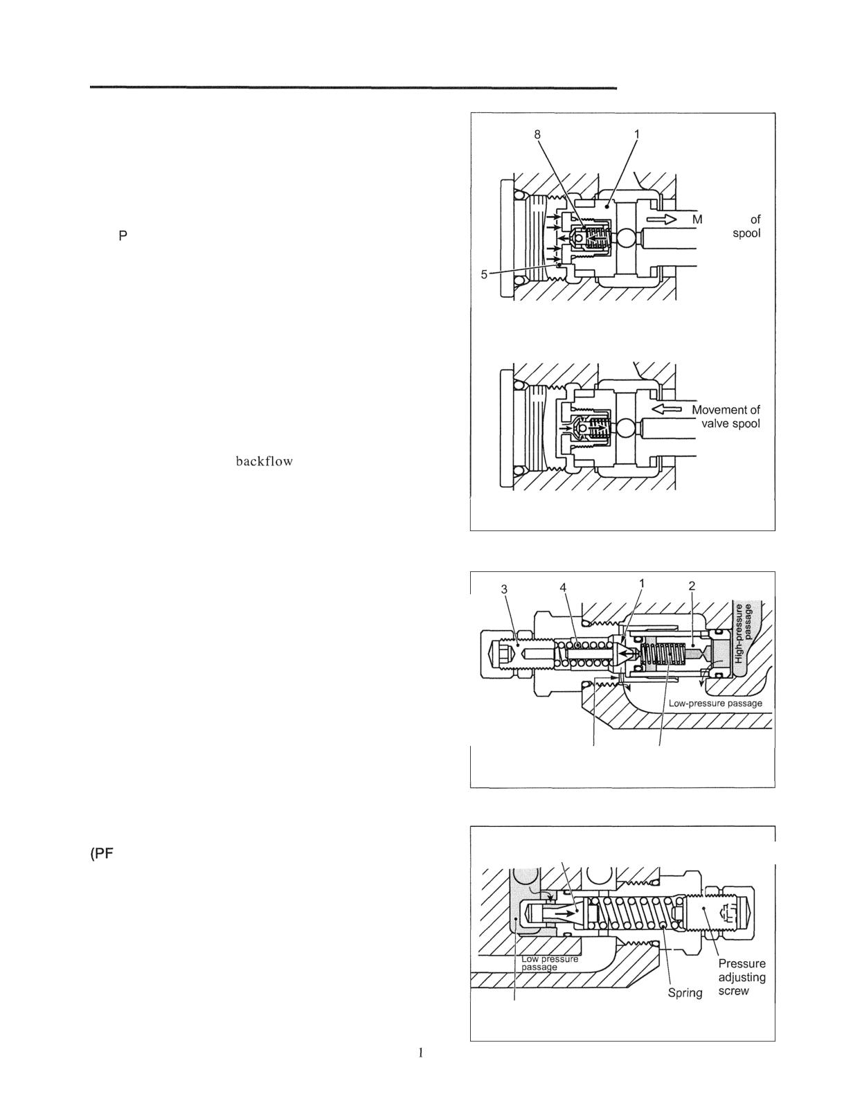
HYDRAULIC SYSTEM
Valve 8 is an orifice provided in oil inflow and outflow
passages of damper valve 5. This orifice diverts
preferentially PF flow in a stable condition (no occurrence
of surging) by controlling the moving speed of valve spool
1.
When extra flow (EF flow) is increased, pressure oil in the
ovement
valve
port flows in damper chamber 5. As the passage is the
orifice on the edge of valve 8 only, movement of valve
spool 1 is slow.
When PF flow is insufficient, it is necessary to increase PF
flow by quickly restricting the EF restricted area. For this,
When increasing extra flow
it is necessary to quickly discharge oil in damper chamber
5. As the orifice on the circumference as well as the orifice
on the valve edge is provided in the passage at this time,
the spool can move to the left quickly.
This action, when pressure of PF flow lowers, can prevent a
kickback phenomenon caused on the steering wheel.
Ball check 3 prevents
of PF flow. This is a
preventive measure for a kickback phenomenon.
When restricting extra flow
209742
Main Relief Valve
This valve is a relief valve with a pilot valve. When
pressure in the P port reaches the set value, poppet valve 1
is pushed to the left (in the illustration), leaving the seat.
Pilot oil in the spring chamber flows in the drain passage.
Then, dump valve 2 moves to the left, releasing a part or all
of main flow to the low-pressure passage. This is a safety
valve to protect the system. To adjust, turn adjusting screw
3 to change preload of spring 4.
Drain passage of
Spring chamber
pilot oil
209743
Steering System Relief Valve
Valve
relief valve)
\
This valve is a relief valve of direct-acting type, and acts
when the steering wheel is fully turned. This is a safety
valve to protect the system. To adjust, turn the adjusting
screw to change preload of the spring.
PF flow passage
209744
1-47
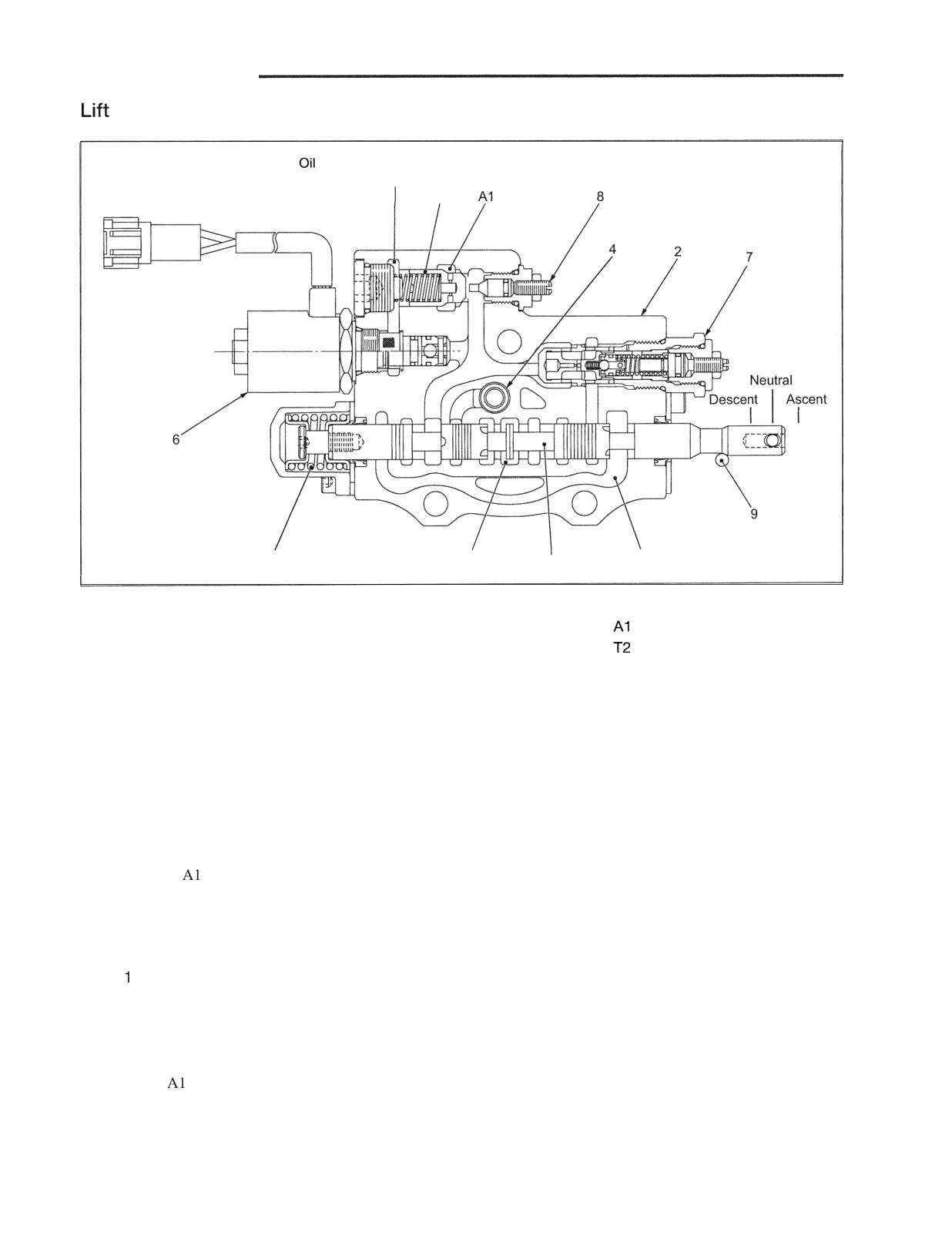
HYDRAULIC SYSTEM
Valve
passage for opening
load check valve
5
3
Center bypass port
1
T2
209745
Main components
1 Lift spool
6 Solenoid valve
: Lift cylinder port
2 Valve body
7 Flow regulator valve
: Tank port
3 Return spring
8 Shut-off valve
4 Check valve
9 Roller for lift lowering limit
5 Load check valve
switch
The above illustration shows the lift control valve when
spool 1 is at the "neutral position."
Neutral position:
Spool 1 is placed at the "neutral position" by return spring
3 and oil in the
port is blocked by load check valve 5.
As the center bypass port is open, pressure oil flows into
the tilt valve without being blocked.
Ascending position of lift cylinder:
Spool moves to the right (as in the above illustration) and
blocks the center bypass port. Pressure in the parallel
feeder (high-pressure passage) rises and pressure oil pushes
open check valve 4, reaching load check valve 5.
Furthermore, pressure oil pushes open load check valve 5,
flows in the
port and in the bottom of the lift cylinder
piston. And it pushes the cylinder rod upward.
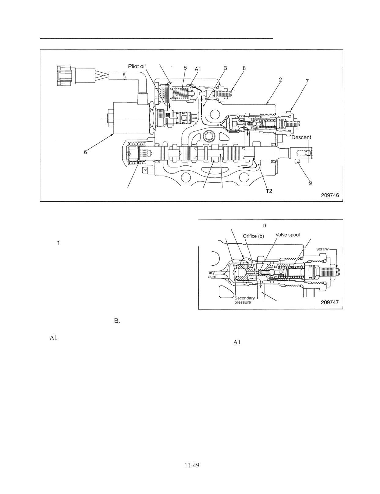
HYDRAULIC SYSTEM
Oil passage for opening load
check valve
Neutral
I
3
Center bypass port
I
Descending position of lift cylinder:
Action of flow regulator valve
The above illustration shows the lift control valve when
Restricted area
spool 1 is at "descending position."
Chamber C
Spring E
Spool
, pushed in body 2, is at the position as shown
Adjusting
in the illustration. The center bypass port is not
blocked. The secondary port of flow regulator valve 7
is open to the T2 port (return passage).
Prim
pres
When spool I is pushed in the body, roller 9 of the lift
lowering limit switch is pushed in, turning the switch
ON. The truck body controller (VCM-1) detects this
Secondary pressure
and feeds current to solenoid valve 6 to activate. When
the solenoid activates, pilot oil behind load check valve
The flow regulator valve keeps the maximum speed
5 is released to the passage
Thus, load check valve
constant during cylinder descent regardless of the load
5 moves to the left (in the illustration) by pressure of
weight on the fork.
the
port and oil in the A l port flows to the T2 port
Oil from the
port (primary pressure) passes through
via flow regulator valve 7.
the restricted area D and its pressure is reduced. This
Shut-off valve 8 forcibly opens load check valve 5 if
pressure-reduced oil (secondary pressure) flows to the
the load check valve does not automatically activate
chamber C through the orifice (b) and moves the valve
due to malfunction of solenoid 6 or any other reason.
spool to the right against the spring E, restricting the
Just loosen the lock nut and push in the screw.
restricted area D. The degree of this restriction is
greater as the primary pressure is higher. Thus, the
secondary pressure is made constant. If the secondary
pressure is constant, the outflow volume is constant.
The right part of this valve is a mechanism to stabilize
valve spool movement.
To adjust the flow volume, turn the adjusting screw.
However, do not adjust in field because it is difficult to
determine whether it is good or bad.
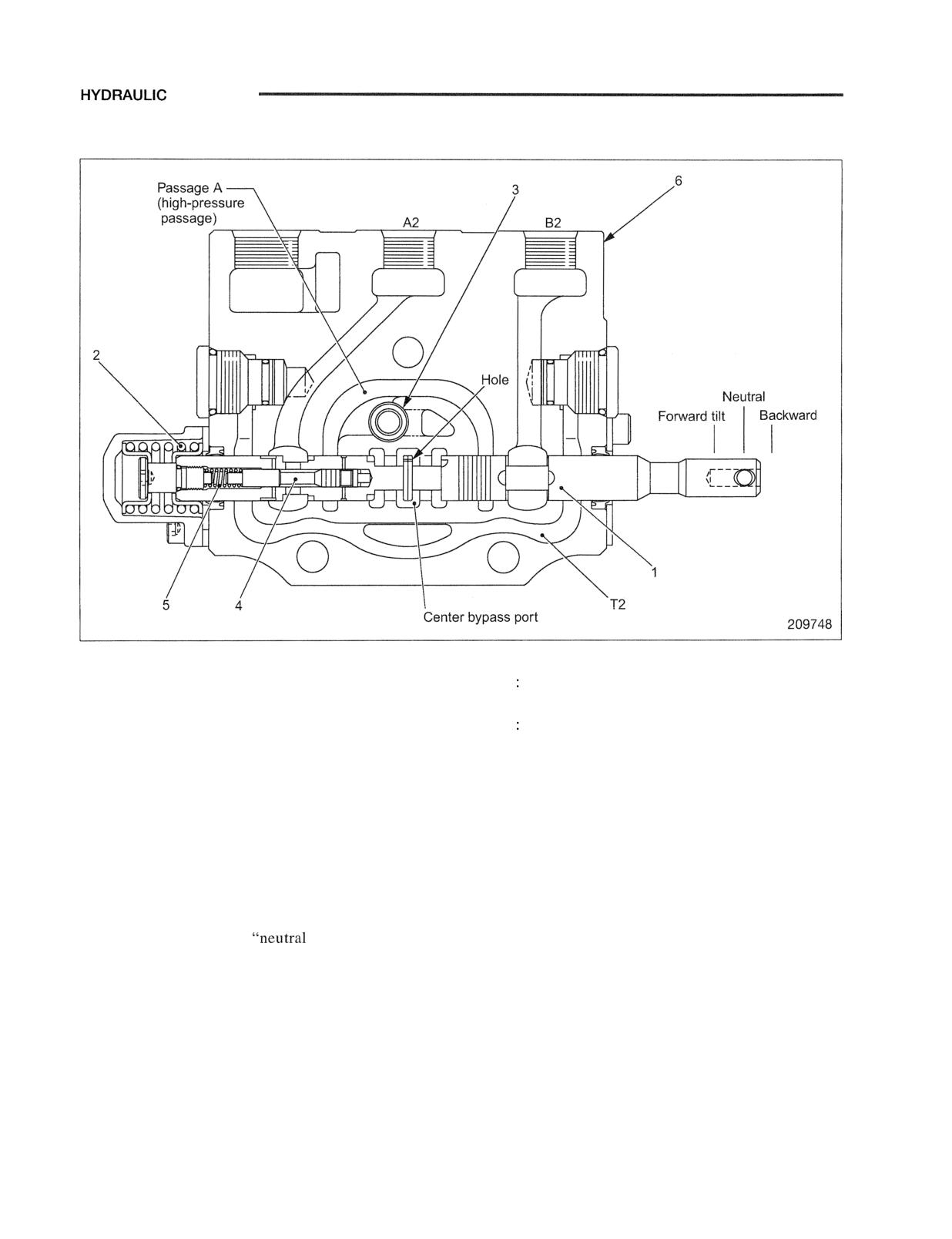
SYSTEM
Tilt Valve
tilt
Main components
1 Tilt spool
A2 To tilt cylinder rod
2 Return spring
B2 : To tilt cylinder head
3 Checkvalve
T2 Tank port (return passage)
4 Tilt lock valve
5 Tilt lock valve spring
6 Valve body
The above illustration shows the tilt control valve when
Mast backward tilt position:
spool 1 is at the "neutral position."
Spool 1 moves to the right. The B2 port is connected to
the T2 port and the A2 port is connected to passage A.
The spool is positioned to block the center bypass port,
Neutral position:
but as the spool is provided with a hole under the land,
Spool 1 is placed at the
position" by return
it does not block completely. This is designed to
spring 2, and both the A2 port and B2 port are blocked
prevent a large amount of oil from flowing at a time to
by the spool.
avoid abrupt movement of the cylinder, a characteristic
As the center bypass valve is open, oil in the bypass
of this valve. When the center bypass port is blocked,
port flows in the attachment valve.
pressure in the parallel feeder rises. Pressure oil pushes
open check valve 3, flows in passage A and flows to the
tilt cylinder rod from the A2 port. At the same time, oil
in the tilt cylinder head flows to the T2 passage. These
two actions pull the rod into the tilt cylinder.
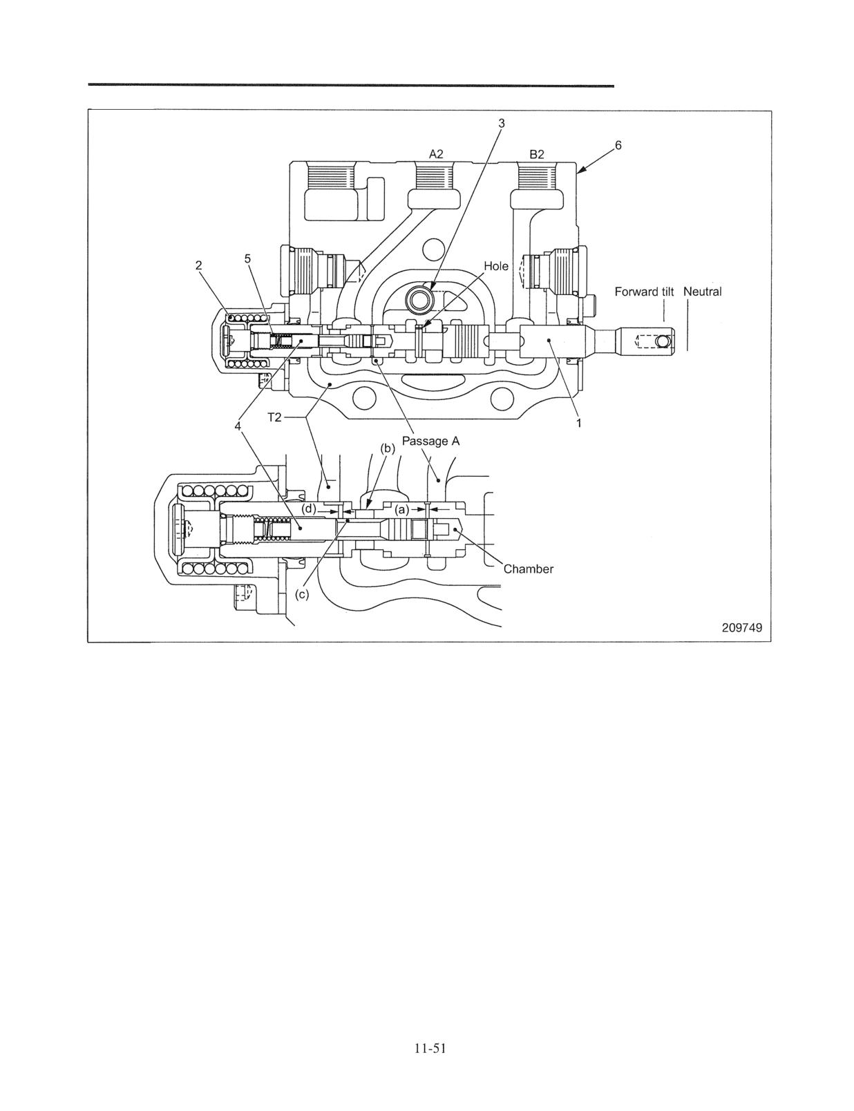
HYDRAULIC SYSTEM
Mast forward tilt position:
port and "opening" of the return passage of the A2 port.
The above illustration shows the tilt control valve when
Tilt lock valve 4 does not operate unless the engine
spool 1 is at the "forward tilt position." Spool 1 is
runs and pressure oil is supplied from the pump. This
pushed into body 6. Then, the B2 port is connected to
valve is a kind of an anti-disaster valve.
passage A. At the same time the center bypass port is
blocked. This blockage, however, is not complete
because there is a hole under the land. This is designed
to prevent abrupt movement of the cylinder, a
characteristic of this valve. As the center bypass port is
blocked, pressure in the parallel feeder rises, pushing
open check valve 3 and pressure oil flows to passage A.
Oil in passage A flows to the tilt cylinder head from the
B2 port and acts to push out the cylinder rod. At the
same time, pressure oil in passage A flows to the
chamber on the right end of tilt lock valve 4 via orifice
(a) and pushes the tilt lock to the left against spring 5.
Then, return oil from the A2 port flows to the hole (b),
passage (c),orifice (d) and passage T2. The tilt cylinder
tilts forward due to pressure oil supplied from the B2
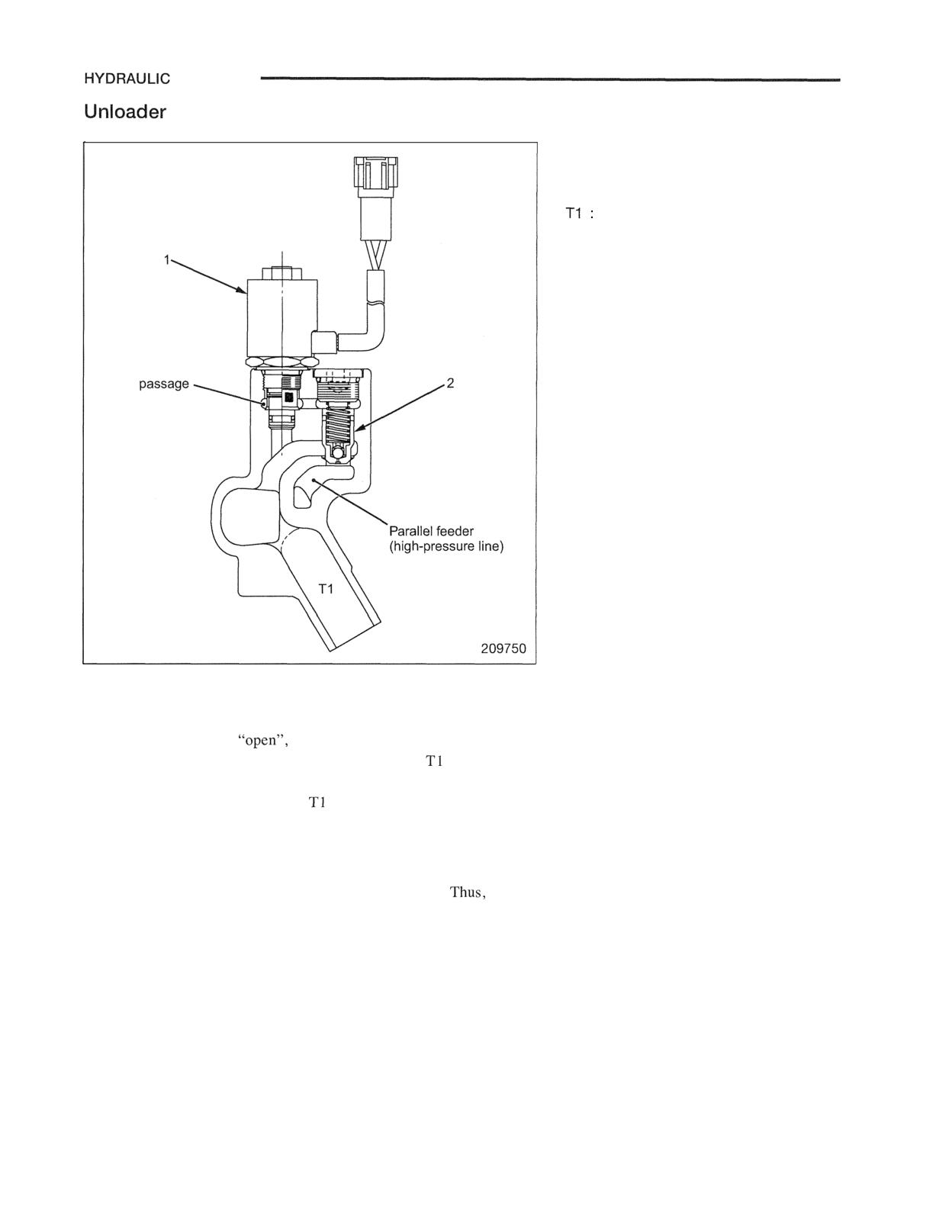
SYSTEM
Valve
1 Solenoid valve
2 Valve
Tank port (return passage)
Pilot
The above illustration shows the unloader valve when the engine
stops.
When the seat switch is
solenoid valve 1 is open and pilot
oil in the back of valve 2 is connected to the
passage.
Therefore, oil in the parallel feeder (high-pressure line) lightly
pushes up valve 2, flowing to the
port. Namely, as hydraulic
pressure cannot be held, the cylinder cannot be moved even if the
valve operating lever is moved.
When an operator sits on the seat, the seat switch is turned ON,
actuating solenoid valve 1 to block the pilot passage.
the
parallel feeder can hold oil pressure. This valve is an anti-disaster
valve.
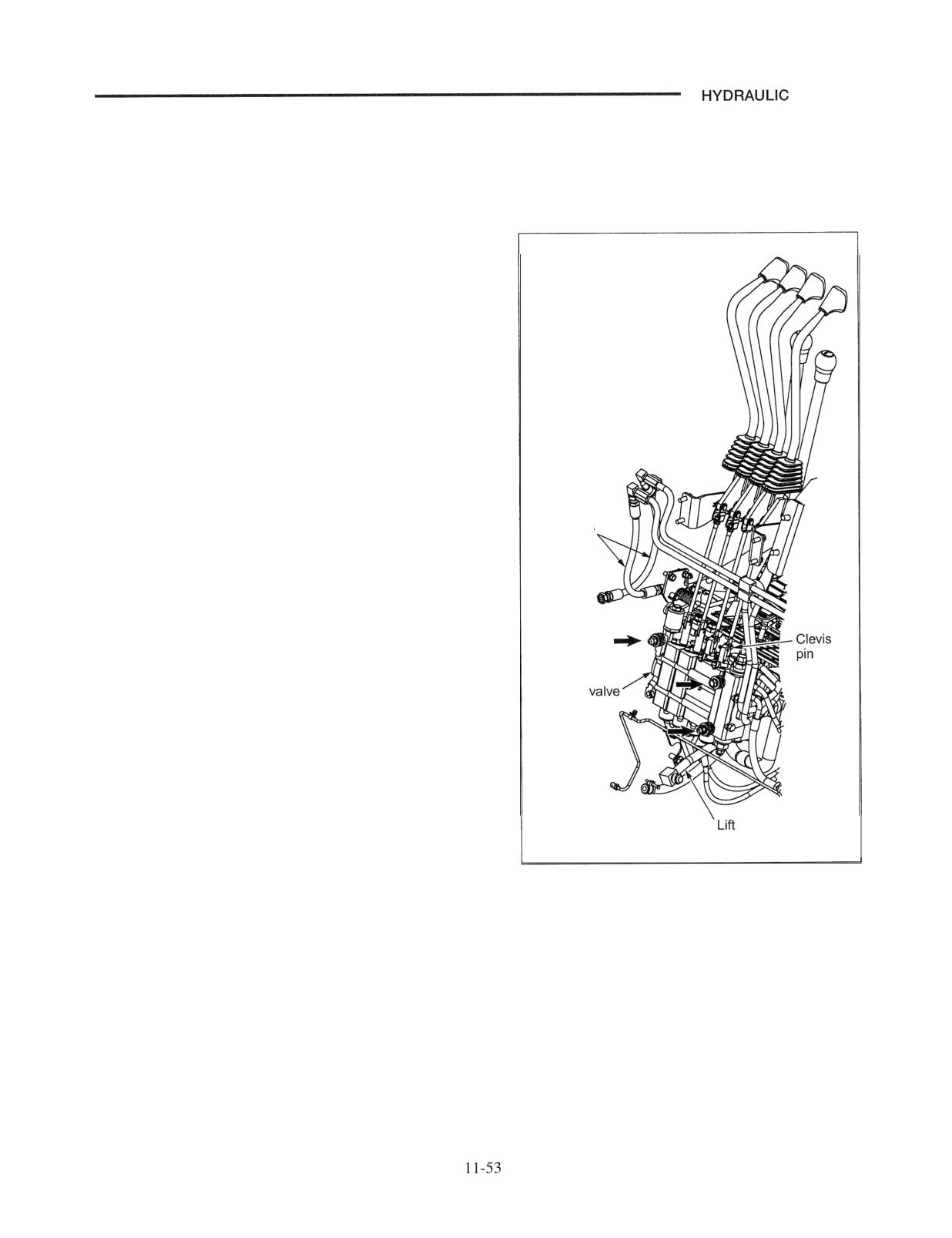
SYSTEM
Removal and Installation of Control Valve
Removal and Installation
Removal
1. Remove the floor plate.
2. Remove the clevis pin of the control lever rod and
separate the rod from the control valve spool.
3. Disconnect each piping from the valve.
(1) Pump delivery hose
(2) Tilt pipe
(3) Lift pipe
(4) Return hose
(5) Supply pipe to steering valve
(6) Return hose from the steering valve
4. Separate the solenoid valve and harness of the
microswitch from the connector.
Tilt hoses
5. Remove valve mounting bolts and nuts (arrows in the
illustration on the right) and remove the valve.
Installation
To install, follow the reverse of removal sequence, and do
the following steps:
Control
Check the hydraulic oil level. Replenish it to the specified
level if the level is low.
hose
210112
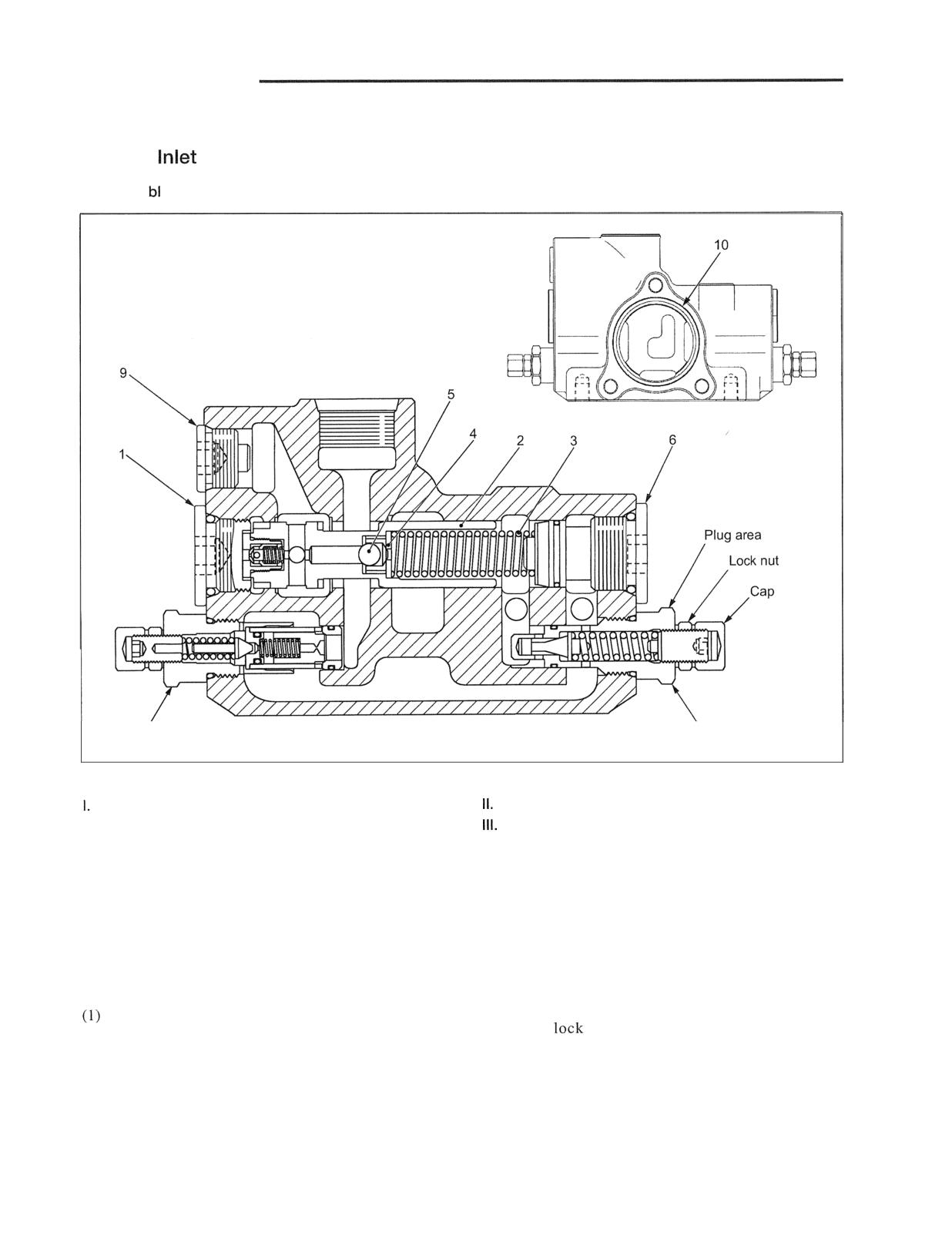
HYDRAULIC SYSTEM
Disassembly and Reassembly
Valve of
Cover Section
Disassem y
7
8
209741
Sequence
Priority valve (1 thru 6)
Main relief valve (7)
1 Plug, O-ring
Steering system relief valve (8)
2 Spool assembly
IV. Other parts (9 and 10)
3 Spring
9 Plug, O-ring
4 Retainer
10 O-ring
5 Ball
6 Plug, O-ring
Suggestions for Disassembly
Note: When loosening the relief valve, apply a spanner
to the plug area of the relief valve to remove. If
Do not disassemble the main relief valve and the
the
nut is loosened by mistake, the set
relief valve of the steering system unless there is
pressure of the relief valve changes. If it is
any abnormality.
loosened by mistake, use a pressure gauge to
reset.
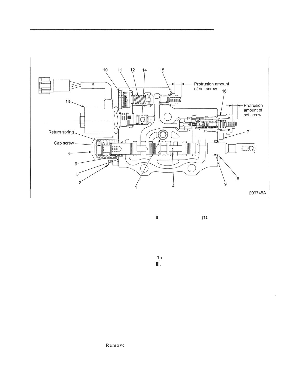
HYDRAULIC SYSTEM
Combination Section
Disassembly of Lift Valve
Sequence
I. Lift valve (1 thru 9)
9 Seal
1 Check valve, spring
Load check valve
thru 15)
2 Bolt
10 Plug, O-ring
3 Cap
11 Spring
4 Spool, return spring
12 Check valve
5 Plate
13 Solenoid valve
6 Seal
14 O-ring
7 Bolt
Shut-off valve
8 Plate
Flow regulator valve (16)
Suggestions for Disassembly
(1) Remove spool 4 from the combination valve body
When disassembling, make a record of the
with the return spring and cap screw attached.
protrusion amount of the set screw. Reassemble it
to the same dimension.
(2) When removing the cap screw, hold the spool in a
vise with soft jaws (hard wooden plate or plastic
(4) Do not, in principle, disassemble or adjust shut-off
plate) and remove the cap screw using a hexagon
valve 15. When disassembling, make a record of
wrench. Be careful of the spring jumping out.
the protrusion amount of the set screw. Reassemble
it to the same dimension.
(3) Do not, in principle, disassemble or adjust flow
regulator valve 16. If internal parts are damaged,
replace it as an assembly.
it as an
assembly without touching the adjusting screw and
lock nut.
11-55
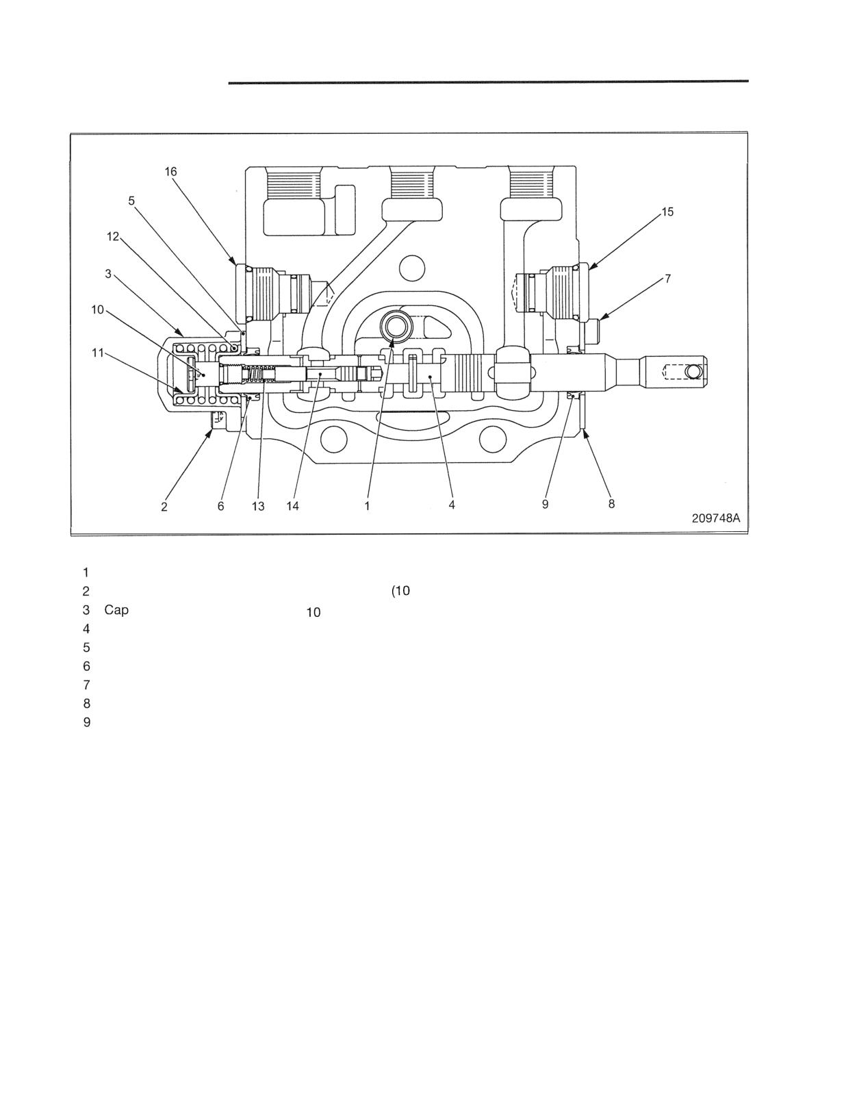
HYDRAULIC SYSTEM
Disassembly of Tilt Valve
Sequence
Check valve, spring
Disassembly sequence of spool
Shut-off valve (15 and 16)
Bolt
sub-assembly
thru 14)
15 Shut-off valve on tilt cylinder
head
Cap screw
Spool sub-assembly
11 Spring retainer
16 Shut-off valve on tilt cylinder
Plate
12 Spring
rod
Seal
13 Spring
Bolt
14 Tilt lockvalve
Plate
Seal
Suggestions for Disassembly
(1) Remove spool 4 from the body with spring 12 and cap
screw 1 0 attached.
(2) When removing cap screw 1 0 , hold the spool in a vise
with soft jaws (hard wooden plate or plastic plate) and
remove the cap screw using a hexagon wrench. Be
careful of the spring jumping out. Remove also the tilt
lock valve.
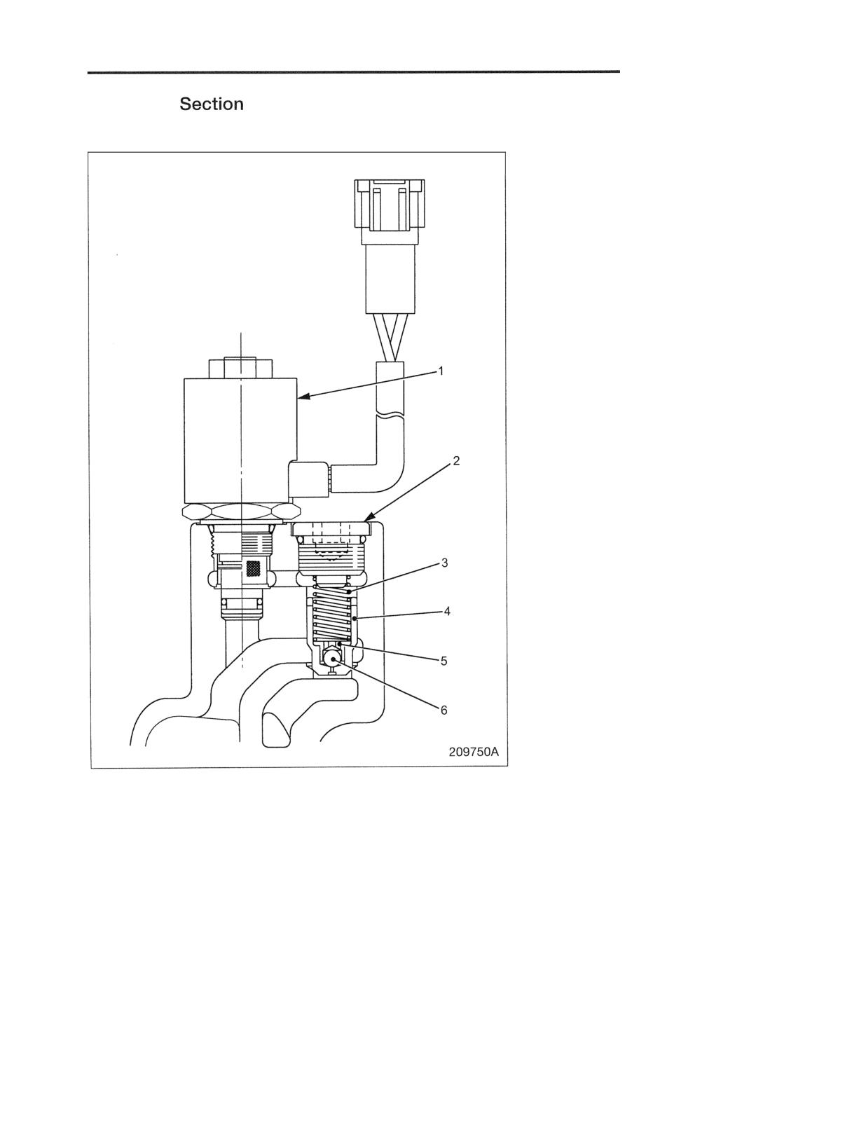
HYDRAULIC SYSTEM
End Cover
Disassembly of Unloader Valve
Sequence
1 Solenoid valve
2 Plug, O-ring
3 Spring
4 Valve
5 Spring retainer
6 Ball
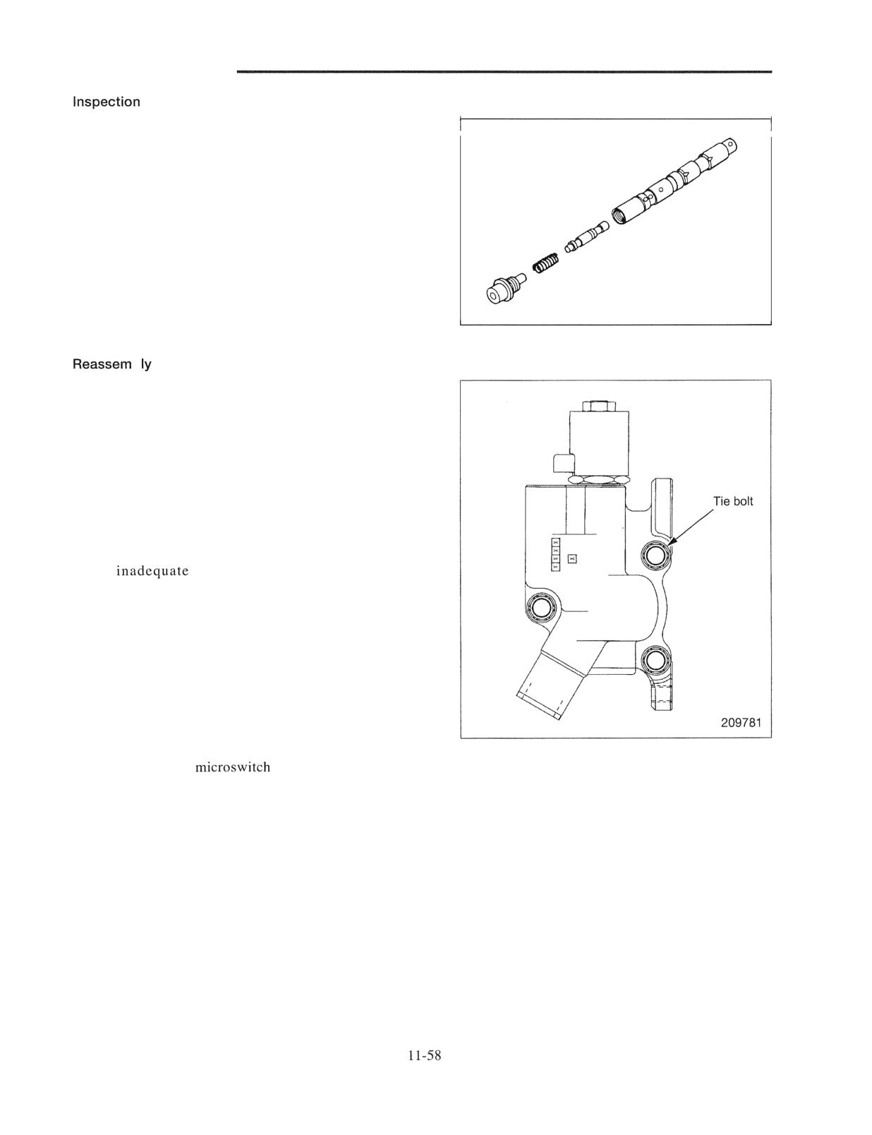
HYDRAULIC SYSTEM
after Disassembly
Valve, spool and return spring
(1) Check the valve body for cracks, damaged sliding
surface and wear of check valve seat.
(2) Check the spool for damage, seizure, bend and
operating force.
(3) Check the tilt lock valve for damage and seizure.
203517
b
To reassemble, follow the reverse of disassembly sequence,
and do the following steps:
(1) Clean disassembled parts with an appropriate solvent.
Remove foreign matters with compressed air.
(2) Apply hydraulic oil to all parts.
(3) Replace O-rings.
(4) Tighten tie bolts.
Tighten tie bolts evenly. Tightening them unevenly or
to
torque can distort the valve body,
resulting in unsrnooth movement of the spool.
(5) Install component valves after appropriate valve bodies
are installed with tie bolts.
(6) Check that the spools slide smoothly.
Note: The valve body and spool have been lapped as a set.
Do not change the combination. When either one of
the two becomes necessary to replace, replace them
together as an assembly.
(7) Check that the
is in position. Adjust its
position if necessary.
MAST AND FORKS
Mast System
I 2.
I
and Function
I 2.
2
Simplex (Dual Panoramic) Mast
to
12.
2
Duplex (Dual Full-free Panoramic) Mast
to
12.
3
Triplex (Triple Full-free Panoramic) Mast
to
12.
4
Mast Operation
12.
5
I. Simplex Mast
12.
5
2. Duplex Mast
12 -
5
3. Triplex Mast
12 -
5
Removal
and installation
-
6
Mast and Lift Bracket Assembly
12 -
6
Simplex Mast
12 -
6
Duplex and Triplex Mast
12 -
9
Disassembly and Reassembly
-
Simplex Mast, Disassembly
12 - 12
Duplex Mast, Disassembly
12 - 14
Triplex Mast, Disassembly
12 - 16
Reassembly
12 - 19
1. Installing lift bracket rollers
12 - 19
2. Installing mast rollers
12 - 22
3. Installing mast strip
12 - 23
4.
second lift cylinders
12 - 23
5. Installing first lift cylinders
12 - 24
6. Connecting chain
12 - 24
7. Installing hydraulic lines
12 - 25
Removal and Installation of Mast Rollers and Strips
without Removing Mast from Ruck
- 28
1. Simplex Mast
12 - 28
2 . Duplex Mast
12 - 29
3. Triplex Mast
12 - 30
Inspection and Adjustment
-
1. Forks
12 - 32
2. Chain Tension Inspection and Adjustment
12 - 33
3. Checking Chain Elongation
12 - 34
4. Adjusting Clearance between Lift Bracket Roller and Inner Mast
12 - 35
5. Mast Roller Clearance Adjustment
12 - 36
6. Mast Strip Clearance, Inspection and Adjustment
12 - 38
7. Tilt Angle Adjustment
12 - 38
8. Right and Left Lift Cylinder Stroke Inspection and Adjustment
12 - 39
Troubleshooting
- 40
Service Data
- 41
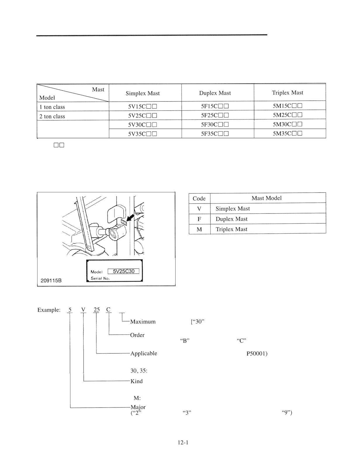
MAST AND FORKS
Mast System
Following table shows a combination of truck and mast
models:
3 ton class
Note:
presents maximum lift height.
Example:
30: Lift Height of 3000 mm
Mast Serial Number Location
Mast Model Code
How to Read Mast Model Code
30
lifting height
stands for 3000 mm (1 18 in.)]
of the minor change
("A" for the original,
for the first change,
for the second change, and so on)
truck model designation (Example:
15: 1 ton class
25: 2 ton class
3 ton class
of mast
V: simplex mast
F: duplex mast
triplex mast
change
for the original,
for the first change, and so on up to
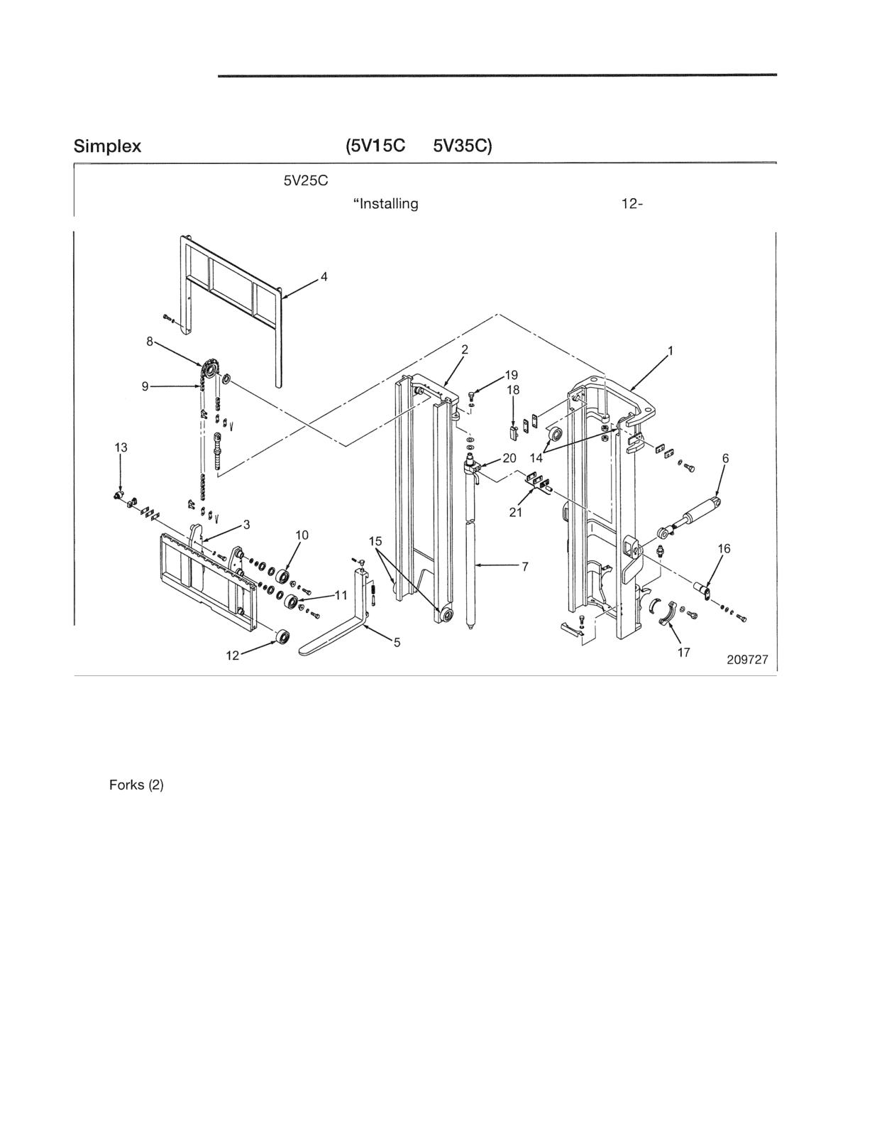
MAST AND FORKS
Structure and Function
(Dual Panoramic) Mast
to
Note: (1) Illustration shows
model.
(2) For hydraulic lines, refer to
Hydraulic Line" on the page
I
Major Components (most parts come in pairs, left and right)
1 Outer mast
9 Chain
17 Mast support cap
2 Inner mast
10 Lift bracket upper roller
18 Mast strip
3 Lift bracket
11 Lift bracket middle roller
19 Lift cylinder upper
4 Backrest
12 Lift bracket lower roller
mounting bolts
5
13 Side roller
20 Cylinder bracket
6 Tilt cylinder
14 Outer mast roller
21 Cylinder clamps
7 Lift cylinder
15 Inner mast roller
8 Chain wheel
16 Tilt cylinder, Tilt socket
mounting pin
Simplex mast features two lift cylinders placed behind
Lift cylinder 7 of a lift height of 3300 mm (130 in.) or
the mast columns, right and left, to provide maximum
less is equipped with down cushioning and no return
visibility.
hose by internal drain.
Mast strips are fitted to the top end of outer mast.
Lift cylinder of a lift height of 3500 mm (138 in.) or
These strips are for backing up the inner mast when the
more is equipped with drain hose.
mast is tilted backward.
For mast operation, refer to "Mast Operation" on page
12-5.
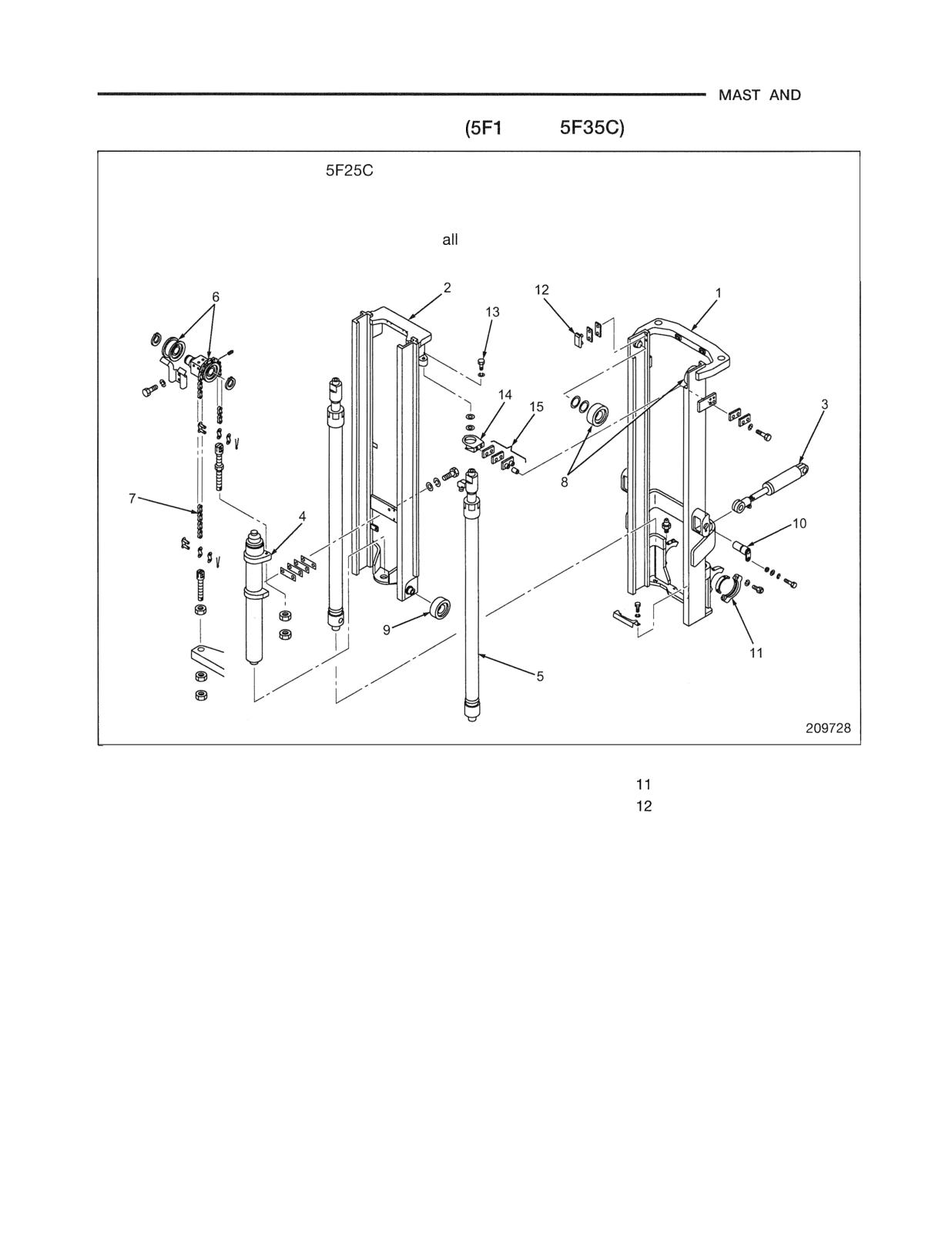
FORKS
Duplex (Dual Full-free Panoramic) Mast
5C to
Note: (1) Illustration shows
model.
(2) For hydraulic lines, refer to "Installing Hydraulic Line" on the page 12-26.
(3) For lift bracket, fork, and backrest, refer to "lllustration of Simplex Mast Structure."
Main parts are almost the same in models.
Major Components (most parts come in pairs, left and right)
1 Outer mast
6 Chain wheel
Mast support cap
2 Inner mast
7 Chain
Mast strips
3 Tilt cylinder
8 Outer mast roller
13 Lift cylinder upper
4 First lift cylinder (one piece)
9 Inner mast roller
mounting bolt
5 Second lift cylinder
10 Tilt cylinder,
14 Cylinder bracket
Tilt socket mounting pin
15 Cylinder clamp
In duplex mast, the first cylinder raises the forks
First cylinder is equipped with upstroke cushioning
without increasing the overall mast height (free-lift)
with internal drain and second cylinder equipped with
until the upper edge of the backrest exceeds the top of
down cushioning.
the mast.
For mast operation, refer to "Mast Operation" on page
The mast assembly consists of the inner mast, outer
12-5.
mast, lift bracket, first lift cylinder and second lift
cylinders.
The first lift cylinder raises the lift bracket, while the
second cylinders operate the inner mast and lift bracket.
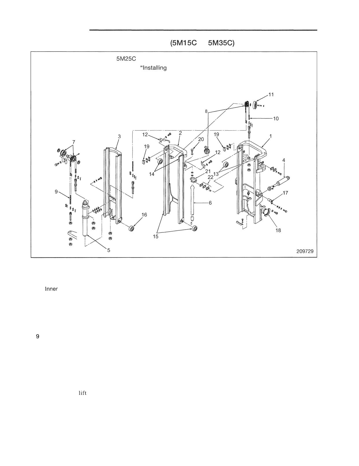
MAST AND FORKS
Triplex (Triple Full-free Panoramic) Mast
to
Note: (1) Illustration shows
model.
(2) For hydraulic lines, refer to
Hydraulic Line" on the page 12-27.
(3) For lift bracket, fork, and backrest, refer to "Illustration of Simplex Mast Structure."
Main parts are almost the same in all models.
Major Components (most parts come in pairs, left and right)
1 Outer mast
10 Second lift chain
17 Tilt cylinder, tilt socket
2 Middle mast
11 Hose pulley
mounting pin
3
mast
12 Chain guard
18 Mast support cap
4 Tilt cylinder
(Right or left type)
19 Maststrips
5 First lift cylinder (one piece)
13 Outer mast roller
20 Lift cylinder upper
6 Second lift cylinder
14 Middle mast upper roller
mounting bolt
7 First lift chain wheel
15 Middle mast lower roller
21 Cylinder bracket
8 Second lift chain wheel
16 Inner mast roller
22 Cylinder clamps
First lift chain
In triplex mast, the free-lift height extends to the top of
First cylinder is equipped with upstroke cushioning and
the mast, and the overall mast height remains the same
second cylinder equipped with down cushioning and
until the upper edge of the backrest exceeds the top of
both cylinders have no return hose by internal drain.
the mast.
For mast operation, refer to "Mast Operation" on page
The mast assembly consists of the inner mast, middle
12-5.
mast, outer mast,
bracket, first lift cylinder and
second lift cylinders.
The first lift cylinder raises the lift bracket, while the
second cylinder operates the three-stage telescopic
mechanism and lift bracket.
12-4
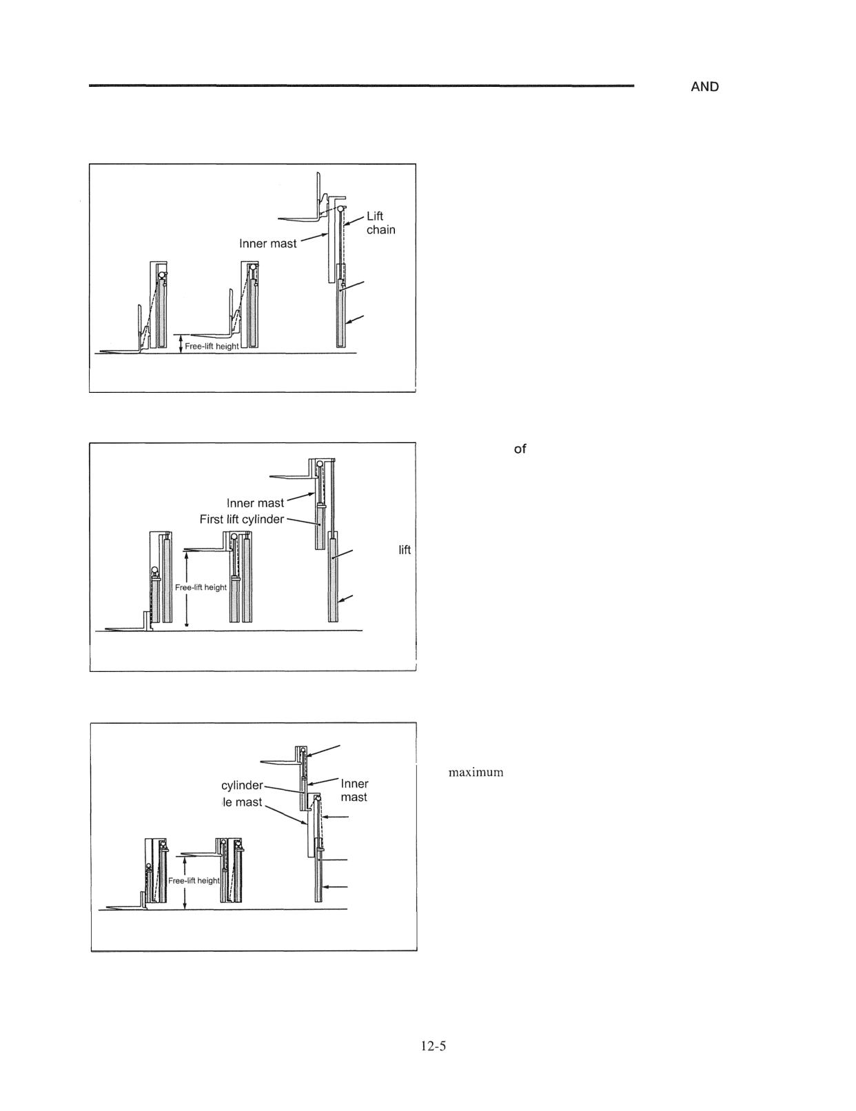
MAST
FORKS
Mast Operation
1. Operation of Simplex Mast
Operation of Mast
The lift cylinders extend, which lifts the forks until the
maximum free-lift height is reached.
The cylinders extend further, causing the inner mast to
lift at the same speed as the rods while at the same time
causing the forks to lift at the speed twice as fast as the
Lift
inner mast.
cylinder
Outer
mast
Forks on
Maximum
Maximum
the ground
free lift
lift
205371
2. Operation of Duplex Mast
Operation Mast
The first lift cylinders extend, bringing the forks to the
maximum free-lift height.
When the first lift cylinder rods have reached the end of
the stroke, the second lift cylinders take over to directly
Second
lift the inner mast to the maximum lift height.
cylinder
The lowering mechanism is the reverse of lifting.
Outer
mast
1
Forks on the
Maximum
Maximum
ground
free lift
lift
205372
3. Operation of Triplex Mast
Operation of Mast
First lift
The first lift cylinders extend, bringing the forks to the
chain
free-lift height.
Fir
lift
mast
When the first lift cylinder rods have reached the end of
the stroke, the second lift cylinders take over to lift the
Second
lift chain
middle mast while at the same time the second lift chain
lifts an assembly of the forks, inner mast and first lift
Second lift
cylinders.
cylinder
Outer mast
The lowering process takes place in the reverse order of
lifting.
Forks on the Maximum
Maximum
ground
free lift
lift
205374
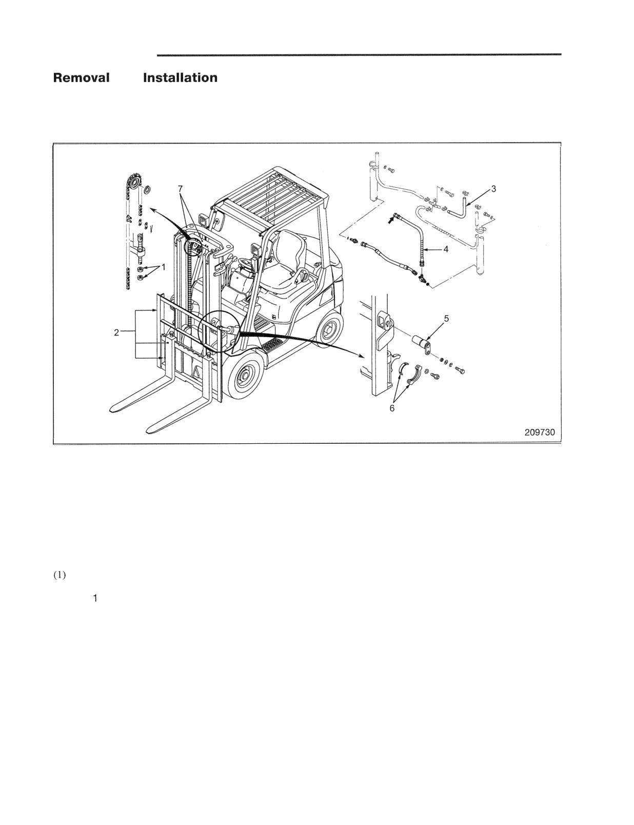
MAST AND FORKS
and
Note: For replacing mast roller without removing mast
from track, refer to page 12-28.
Mast and Lift Bracket Assembly
Simplex Mast Removal
Sequence
1 Nuts
5 Tilt socket pin
2 Backrest, Lift bracket, Forks
6 Mast support bearing cap, Bushing
3 Return hose (hi-lift model)
7 Inner mast, Outer mast, Lift cylinder
4 High-pressure hose
Suggestions for Removal
1. Removing lift bracket
Tilt the mast forward, and lower the inner mast to
the bottom. Slacken the lift chains, and remove the
nuts from the anchor bolts.
(2) Tilt the mast back to vertical position. Raise the
inner mast until the lift bracket 2 becomes free.
Then, slowly back the truck away, from the lift
bracket and fork assembly.
Note: Before proceeding any mast overhaul, measure
the clearance between mast and rollers.
Knowing which roller should be replaced or
which shims need adjustment in advance allows
efficient maintenance work.
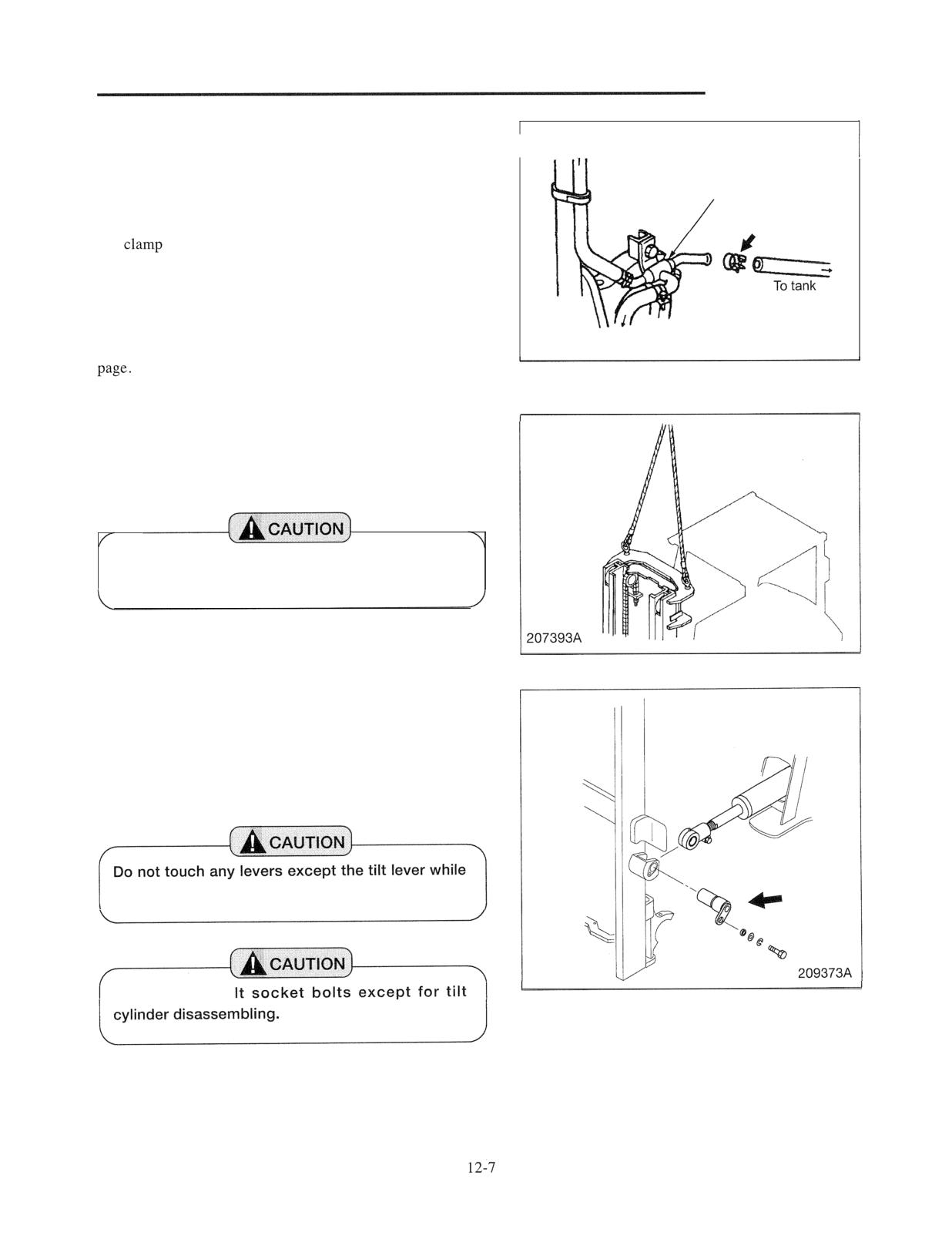
MAST AND FORKS
2. Disconnecting return hose for lift cylinder
To right lift cylinder
(For high-lift cylinder model)
I
A
(1) Start the engine and raise the mast in the highest
Return connector
position.
(2) Stop the engine and disconnect the hose 3 at the hose
(Allow) of return connector.
(3) Lower the mast.
3. Disconnecting high-pressure hoses for lift cylinder
Place the mast in the bottom position, disconnect the hose 4
To left lift cylinder
at the arrow position in the illustration on the previous
204874
4. Separating tilt cylinders
(1) Hitch a sling to the upper cross-member of the outer
mast, then lift with a hoist.
Be sure to use a hoist having a capacity enough
to support the mast assembly.
(2) Place wood blocks under the tilt cylinder mounting
section and remove the tilt socket pins, and separate the
mast from the tilt cylinders.
(3) Start the engine, and pull back the tilt lever to retract
the tilt cylinder rods.
the engine is running.
Never loosen ti
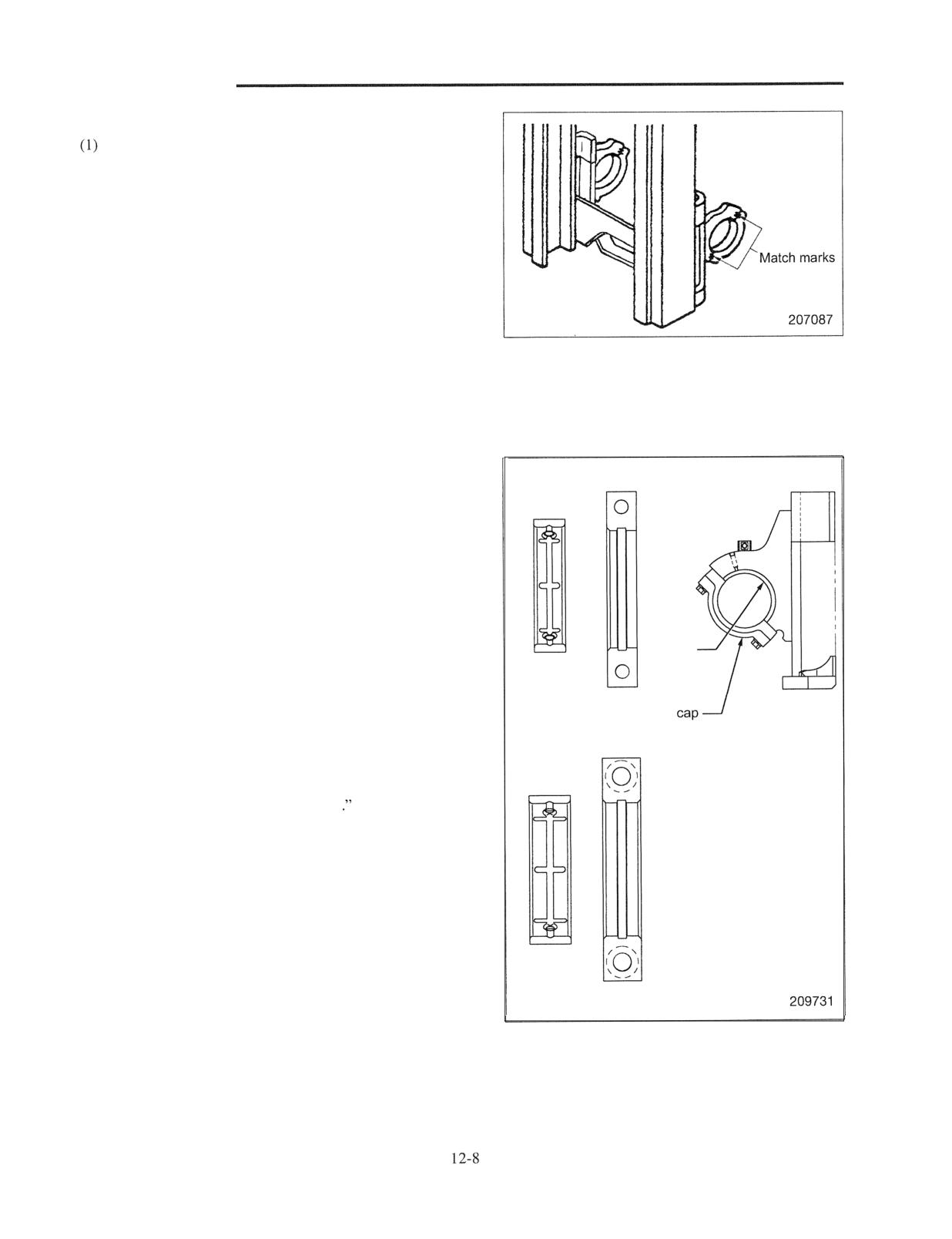
MAST AND FORKS
5. Removing mast support bearing caps
Mark caps to ensure the caps are reinstalled in original
positions during reassembly.
(2) Remove cap mounting bolts. Dismount the mast
assembly from truck in the suspended condition. With
the lift bracket side facing up, place the mast assembly
horizontally on wooden blocks on a level ground.
Note: Lay the mast assembly on a space large enough to
disassemble the parts.
Installation
To install, follow the removal sequence in reverse with
followings in mind.
1. Mast Support
lnner bushing lnner cap
(1) Apply grease to the inner surfaces of caps and mast
support bushings.
(2)-a 1 ton class:
When installing caps, make sure the wider chamfered
side faces toward the center of the chassis.
(2)-b 2,3ton classes:
Chamfering is the same both in the right and left
bushing
sides. Be sure to reassemble in the same position as it
was.
(3) When applying grease, place wood blocks under the
1 ton class
mast. By doing so, it is easily greased.
2. Adjust the chain tensions
Refer to the "Chain Tension Adjustment
3. Bleeding lift cylinders
Start the engine, raise and lower the lift bracket with
several strokes to bleed the cylinder.
After proper operation is confirmed, check the oil level in
hydraulic tank.
2, 3 ton classes
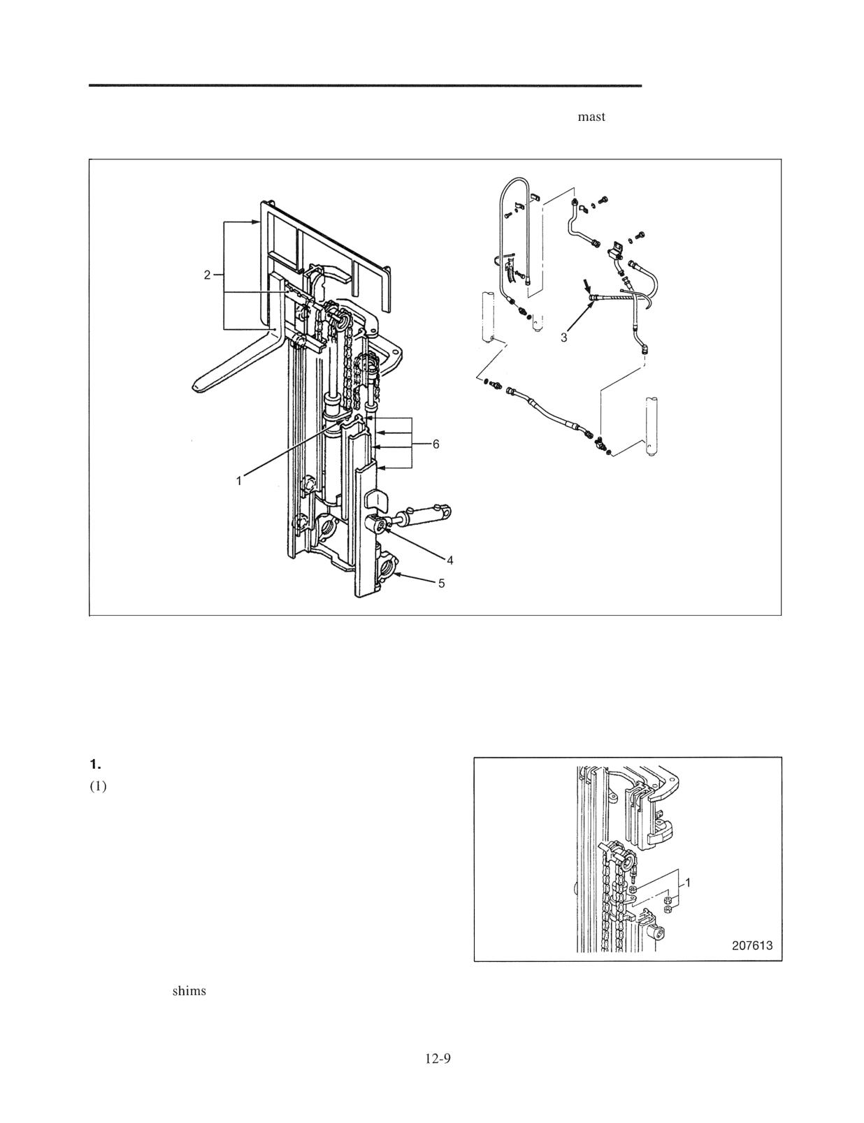
MAST AND FORKS
Duplex Mast and Triplex Mast Removal
Note: For replacing
roller without removing mast
from track, refer to page 12-29 or 12-30.
Illustration shows triplex mast.
209732
Sequence
1 Nuts
4 Tilt socket pin
2 Backrest, Lift bracket, Fork
5 Mast support bearing cap, Bushing
3 High-pressure hose
6 Mast, Lift cylinders
Suggestions for Removal
Removing lift bracket
Lower lift bracket, and place wood blocks under
the assembly. Tilt the mast forward, lower the
inner mast to the bottom, then remove nuts 1 from
the anchor bolts of the first lift chains.
(2) Tilt the mast back to vertical position. Raise the
inner mast until main rollers of the lift bracket
become free. Then, back the truck away, from the
lift bracket.
Note: Before proceeding any mast overhaul, be sure to
measure the clearance between mast and rollers.
Knowing which roller should be replaced or
which
need adjustment in advance allows
efficient maintenance work.
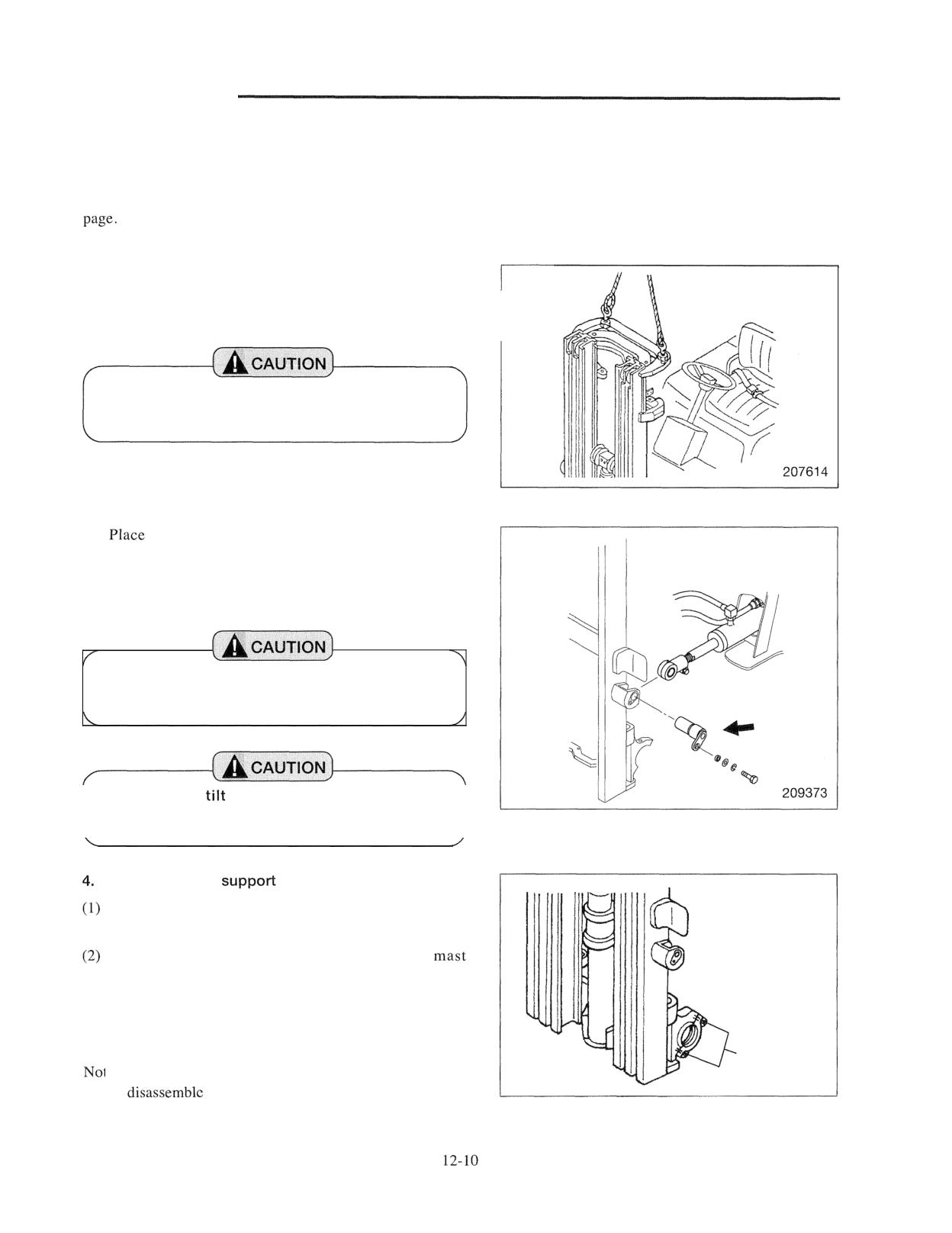
MAST AND FORKS
2. Disconnecting high-pressure hoses for lift
cylinder
Place the mast in the bottom position, disconnect the hose 3
at the arrow position in the illustration on the previous
3. Separating tilt cylinders
(1) Hitch a sling to the upper cross-member of the outer
mast, then lift with a hoist.
Be sure to use a hoist having a capacity enough
to support the mast assembly.
(2)
wood blocks under the tilt cylinder mounting
section and remove the tilt socket pins, and separate the
mast from the tilt cylinders.
(3) Start the engine, and pull back the tilt lever to retract.
Do not touch any levers except the tilt lever while
the engine is running.
Never loosen
socket bolts except for tilt
cylinder disassembling.
I
I
Removing mast
bearing caps
Mark caps to ensure the caps are reinstalled in original
positions during reassembly.
Remove cap mounting bolts. Dismount the
assembly from truck in the suspended condition. With
the lift bracket side facing up, place the mast assembly
horizontally on wooden blocks on the level ground.
Match marks
te: Lay the mast assembly on a space large enough to
207615
the parts.
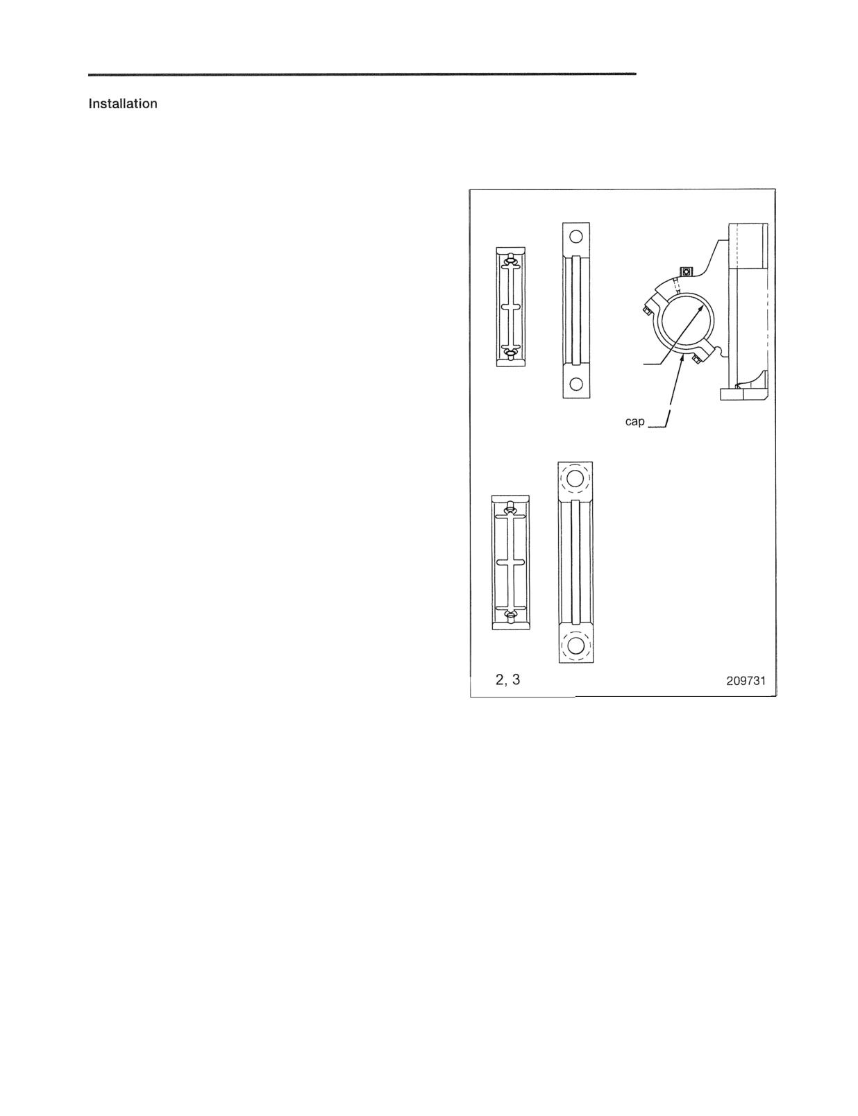
MAST AND FORKS
To install, follow the removal sequence in reverse with
followings in mind.
1. Mast Support
lnner bushing lnner cap
(1) Apply grease to inner surfaces of caps and mast
support bushings.
(2)-a 1 ton class:
When installing caps, make sure the wider chamfered
side faces toward the center of the chassis.
(2)-b 2 , 3 ton classes:
Chamfering is the same both in the right and left
sides. Be sure to reassemble in the same position as it
bushing
was.
(3) When applying grease, place wood blocks under the
1 ton class
mast. By doing so, it is easily greased.
2. Adjust the chain tensions
Refer to the "Chain Tension Adjustment."
3. Bleeding lift cylinders
In the duplex mast, the second lift cylinders are provided
with air bleeding screws.
After installing the mast, start the engine, raise and lower
the lift bracket with several strokes and loosen the screws
to bleed.
In the triplex mast, no air bleeding screws are provided.
ton classes
Raise and lower the lift bracket with several strokes to
bleed the air trapped below the piston.
After proper operation is confirmed, check the oil level in
hydraulic tank.
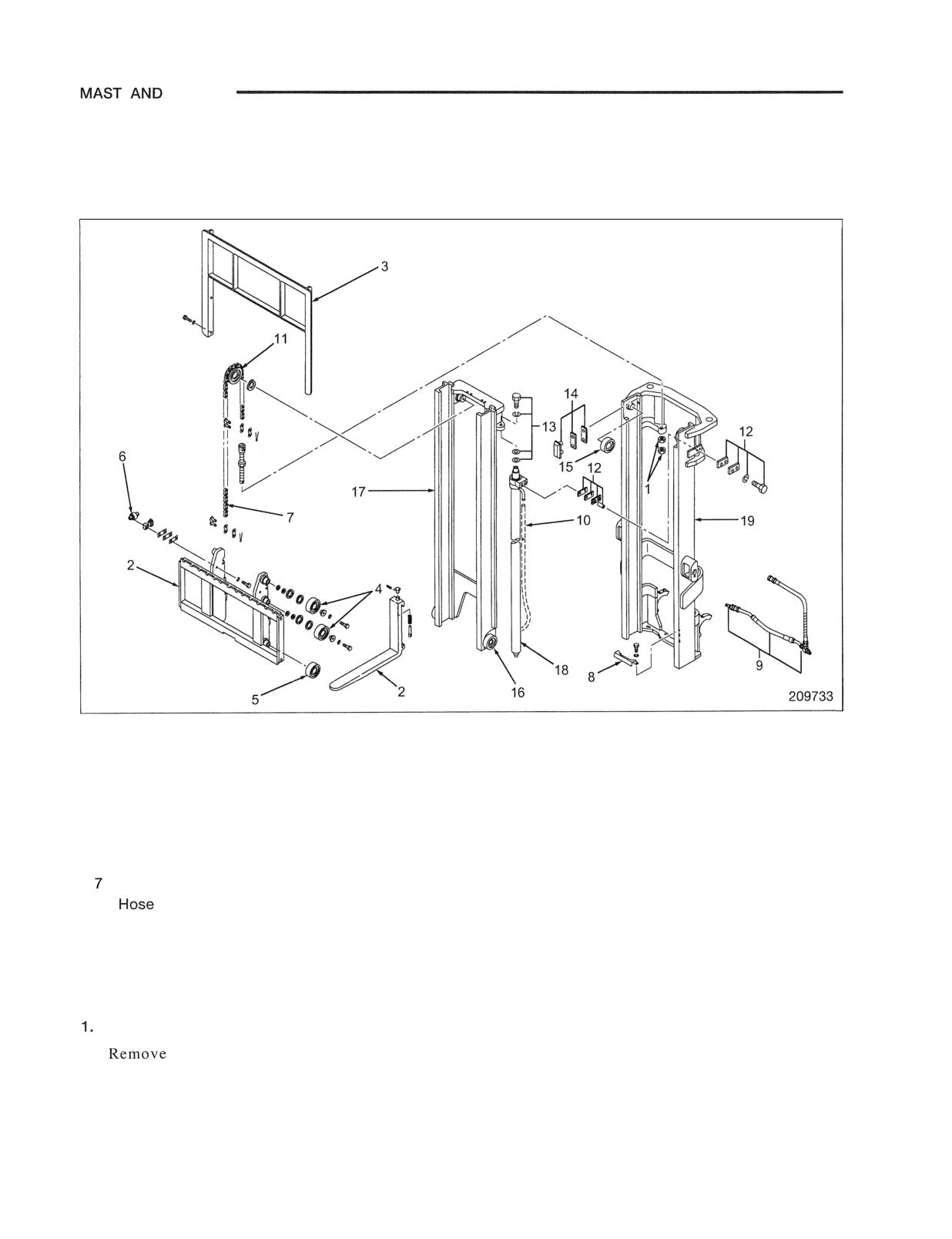
FORKS
Disassembly and Reassembly
Simplex Mast
Disassembly
1
Sequence
1 Nuts
11 Chain wheel
2 Forks, Lift bracket
12 Cylinder clamps, Seats, Shims, Cushion,
3 Backrest
Collar, Bolts
4 Lift bracket upper, Lower rollers
13 Bolt, Shims
5 Lift bracket lower rollers
14 Mast strips, Shims
6 Lift bracket side rollers
15 Outer mast main rollers
Chain
16 Inner mast main rollers
8
guard
17 Inner mast
9 Lift hose (high pressure), Rubber hose,
18 Lift cylinders
T-joint, Down safety valve
19 Outer mast
10 Return hose (high lift mast)
Suggestions for Removal
Removing mast strips and main rollers
bolts 12, 13 to free lift cylinder 18.
Displace the tops of the two lift cylinders from
inner mast 17. Slide inner mast toward the bottom
of outer mast 19, and remove main rollers 15, 16
and mast strips 14.
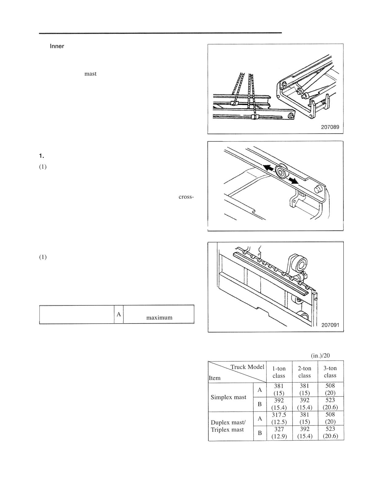
MAST AND FORKS
2.
mast removal
After removing the main rollers, hitch a sling to the inner
mast cross-member and slide the inner mast to the upper
side of the outer
to clear the outer mast roller shafts.
Hitch a sling to the inner mast again and remove it from the
outer mast.
Inspection after disassembly (all models)
Mast
Check each roller for wear, binding or other defects.
(2) Check each roller on rolling surface for pitting or other
defects.
(3) Check the mast member and the welded joints of
members, shafts and supports for cracks.
(4) Check the mast support bushings for wear or other
defects.
207090
2. Lift bracket
Check the main rollers and side rollers for smooth
rotation. Inspect each roller for wear and cracks.
(2) Check the welded portions of the bracket for cracks.
(3) Check the finger bar for bend or distortion.
A: Standard value
5 mm (0.2 in.)
Distortion of finger bar
Chain elongation
3. Lift chains, chain wheels and chain wheel supports
A: Standard value B: Repair or service limit
(1) Measure the length of each chain to make sure that two
Unit : mm
links
chains are equal in length. Also check the chains for
wear, indication of breakage, link binding and twist.
(2) Check each chain anchor bolt for cracks or defects on
thread.
(3) Check each chain wheel support and chain wheel for
crack or wear. Check that the wheels rotate smoothly.
4. Mast strips
Check the mast strips for damage, wear or distortion.
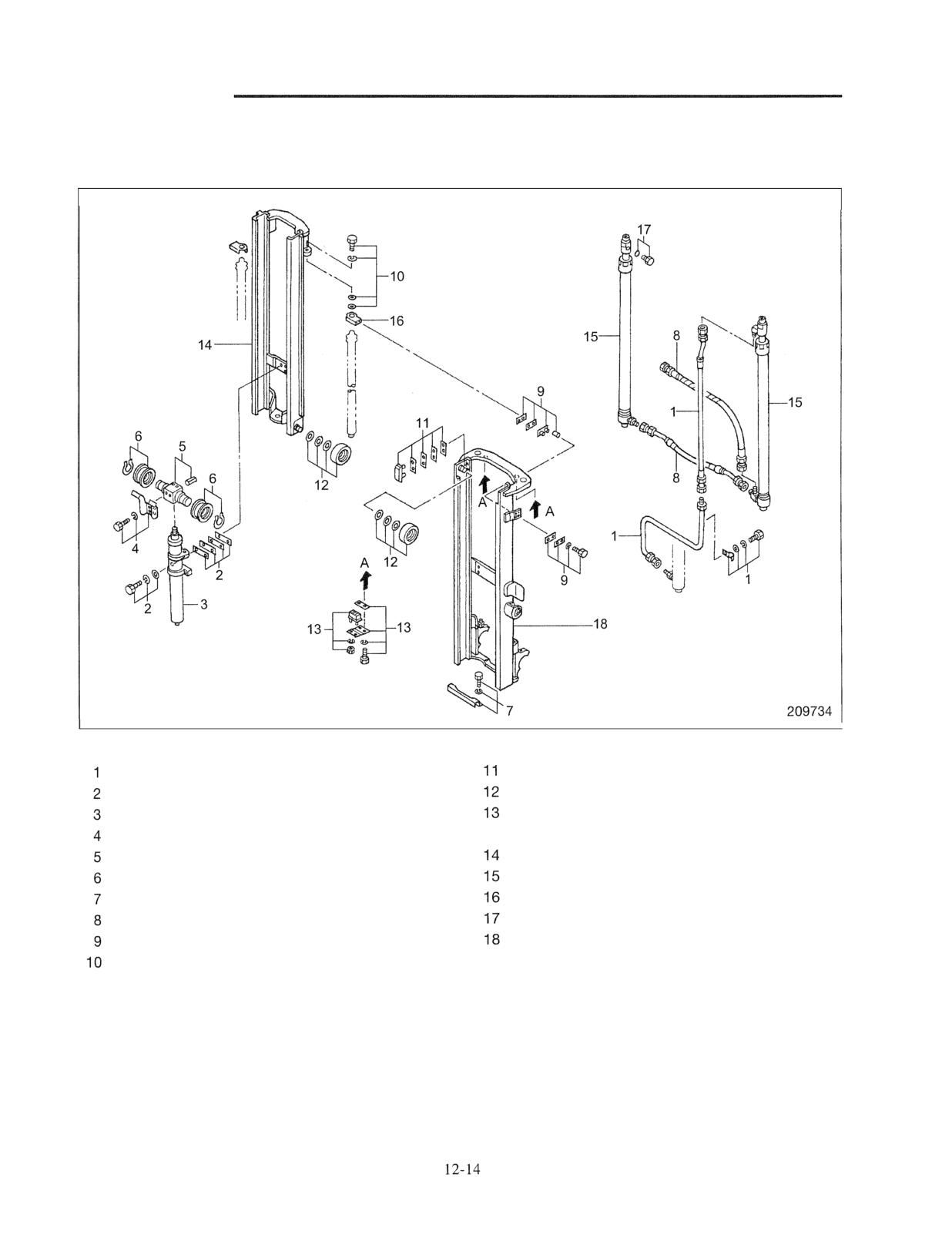
MAST AND FORKS
Duplex Mast
Disassembly
I
Sequence
Lift hose (high pressure), Clamp
Mast strips, Shims
Shims, Bolts, Washers
Mast Rollers
First lift cylinder
Stopper cushion, Cushion plate, Shim, Bolt,
Chain guard
Washer
Chain wheel support, Pin
Inner mast
Chain wheels, Snap rings
Second lift cylinders
Hose guard, Bolt, Washer
Cylinder brackets
High-pressure hose
O-rings, Plugs
Seats, Shims, Cushions, Collars
Outer mast, Grease nipples
Bolts, Washers, Shims
Note: The lift bracket disassembly procedure is the
same as for the simplex mast.
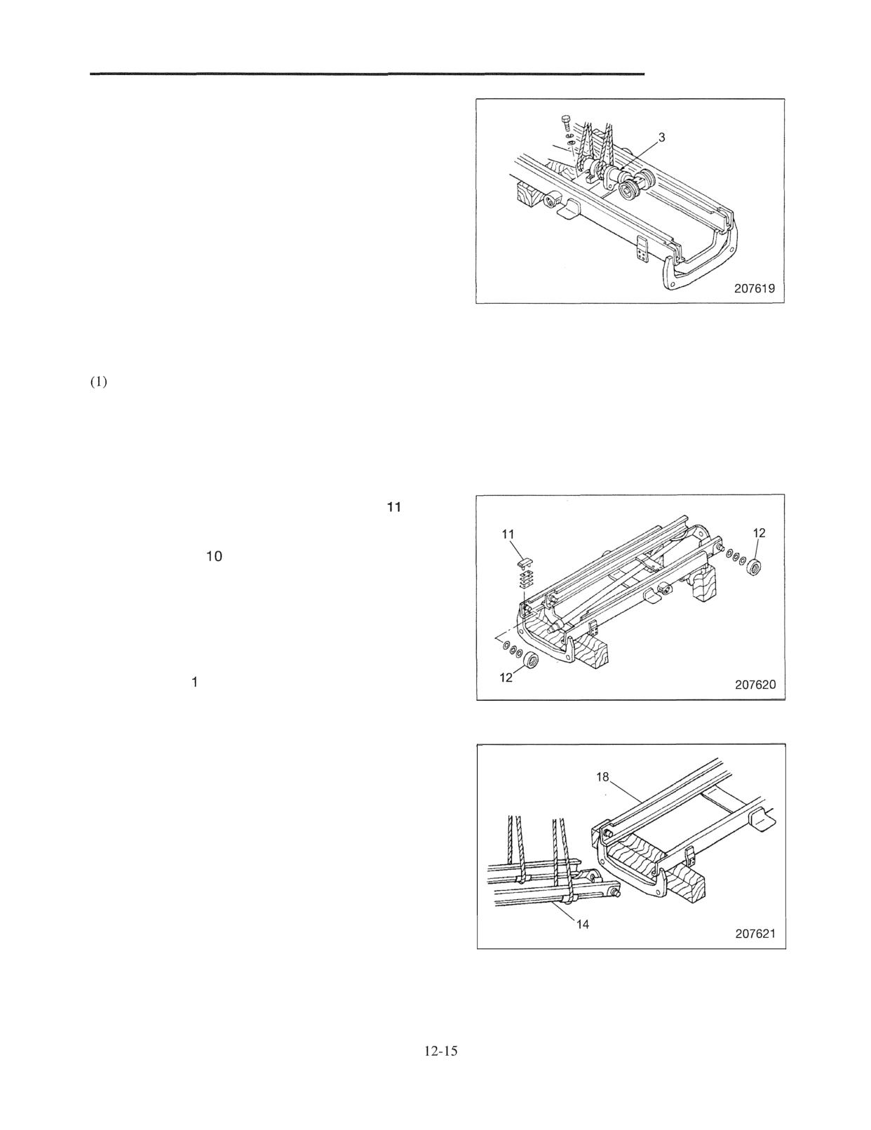
MAST AND FORKS
Start by:
(a) With the lift bracket facing up, place the mast
horizontally on wood blocks. Place a wood block as a
wedge to prevent the inner and middle masts from
sliding.
(b) Before disassembling the mast and fork assembly,
measure and record all clearances between each lift
bracket and roller and between each mast and roller.
Recorded measurements will be helpful when replacing
rollers or selecting shims to adjust clearances.
Suggestions for Disassembly
1. Removing first lift cylinder 4
Remove retaining bolts 2 from the first lift cylinder
(2) Hitch slings on first lift cylinder, and gently remove the
cylinder.
Use two slings. Wind or tie slings securely to prevent
slipping.
2. Removing main rollers 12 and mast strips
(I) Remove clamp bolts 9 from the second lift cylinders.
(2) Remove bolts
from the upper rod sections of the
second lift cylinders, and place the cylinders on the
outer mast.
(3) Check the number of shims and the shim thickness at
the rod end sections.
(4) Lower the inner mast, then remove main rollers 12 and
mast strips 1 .
3. Removing inner mast 14
Using slings, lift and remove inner mast 14, steering it
clear of the roller shaft sections of outer mast 18.
inspection after disassembly
Follow the same inspection procedure as for the simplex
mast.
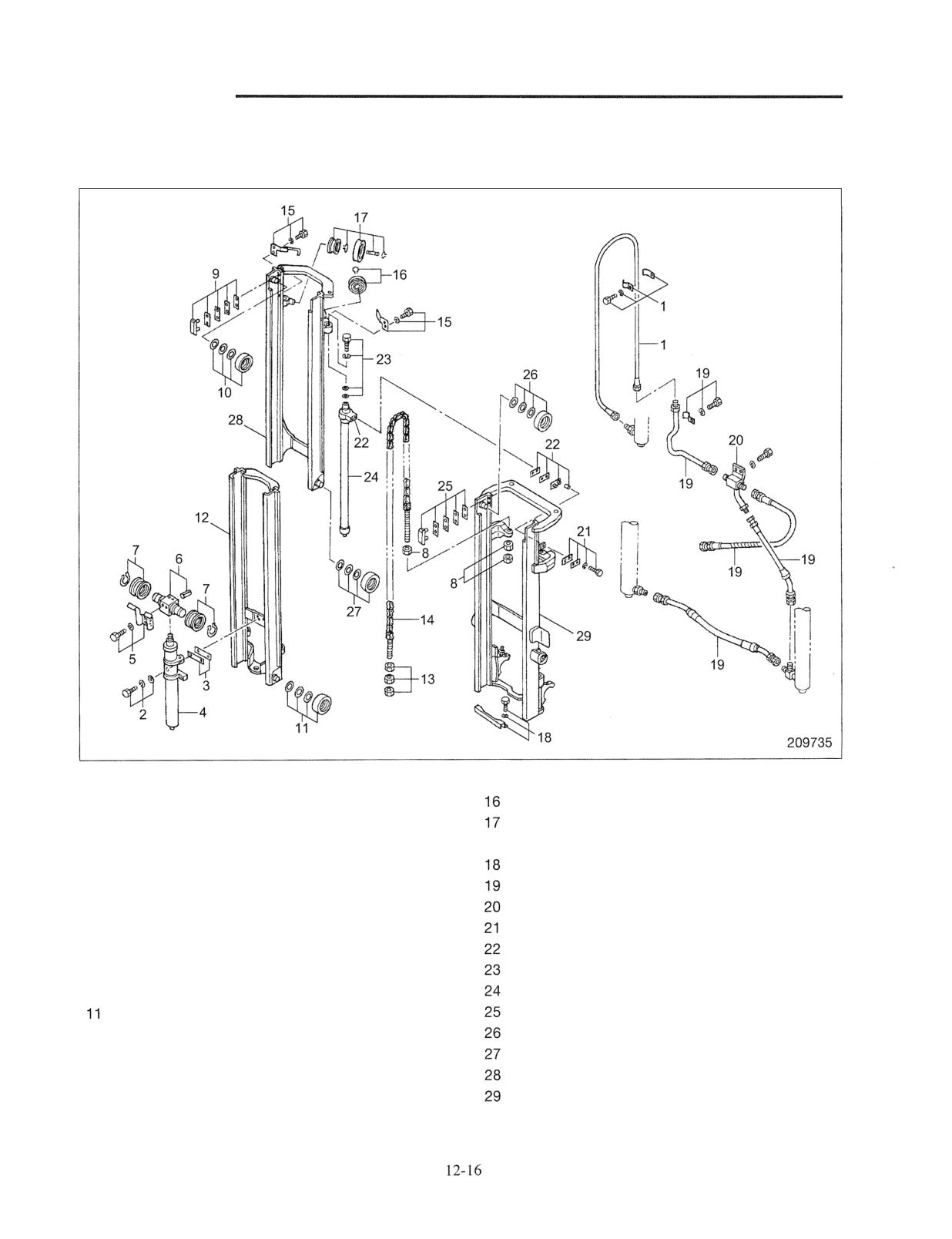
MAST AND FORKS
Triplex Mast
Disassembly
Sequence
1 Hose for first lift cylinder, Clamp, Bolt, Washer
Snap rings, Chain wheels
2 Bolts, Washers
Snap rings, Hose pulleys, Shafts, Snap rings,
3 Shims
Chain wheels
4 First lift cylinder
Hose guard, Bolt, Washer
5 Chain guard
Hose, Clamp, Bolt, Washer
6 Chain wheel support, Pin
Joint, Connector, Bolt, Washer
7 Snap rings, Chain wheels
Bolts, Seats, Cushions, Collars
8 Nuts (chain for second lift cylinder)
Cushions, Shims, Bracket
9 Mast strips, Shims
Bolts, Washers, Shims
10 Main rollers, Shims
Second lift cylinders
Main rollers, Shims
Mast strips, Shims
12 Inner mast
Main rollers, Shims
13 Nuts
Main rollers, Shims
14 Lift chains (for second lift cylinders)
Middle mast
15 Chain guards, Bolts, Washers
Outer mast, Grease nipples
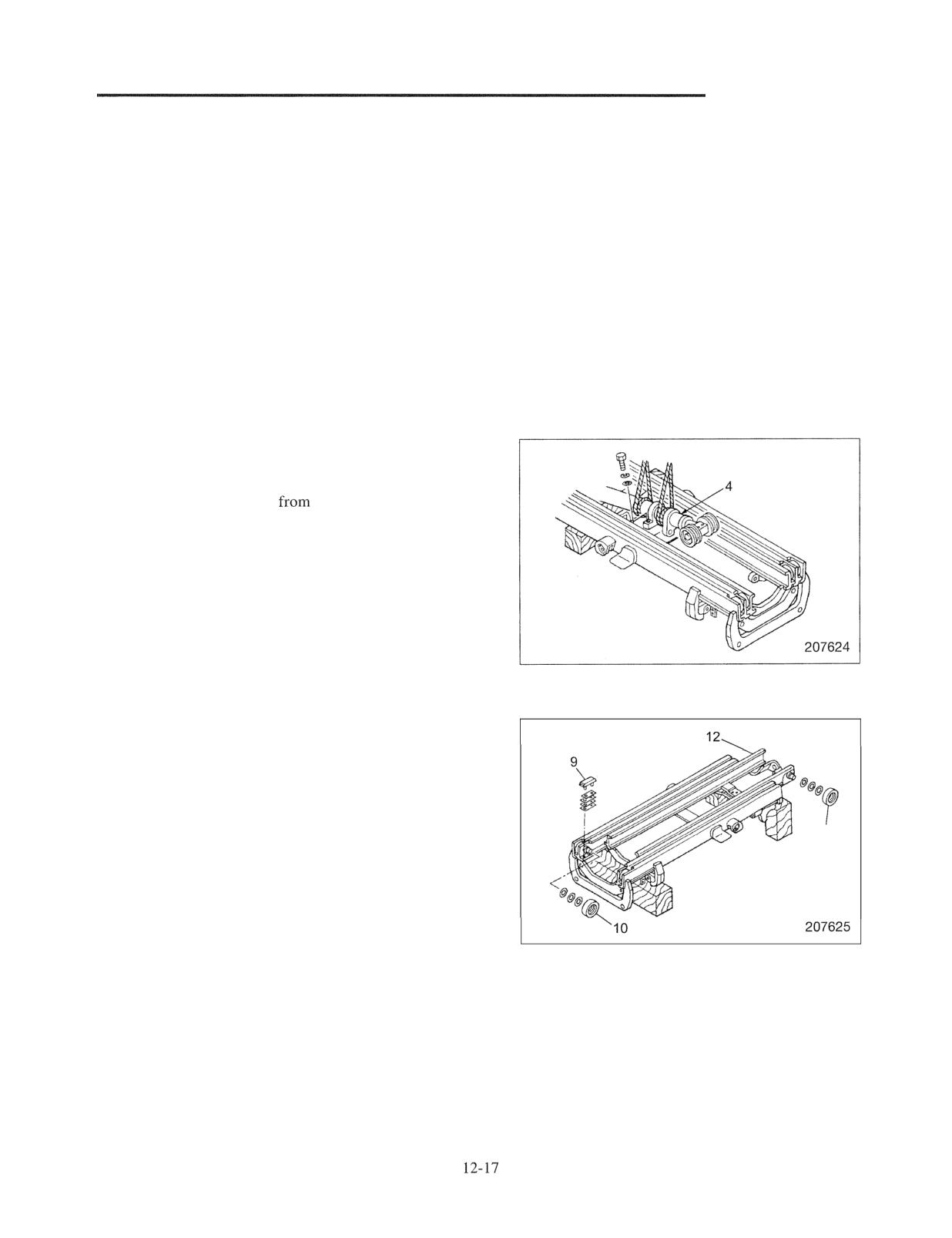
MAST AND FORKS
Note: The lift bracket disassembly procedure is the same
as for the simplex mast.
Start by:
(a) With the lift bracket facing up, place the mast
horizontally on wood blocks. Place a wood block as a
wedge to prevent the inner and middle masts from
sliding.
(b) Before disassembling the mast and fork assembly,
measure and record all clearances between each lift
bracket and roller and between each mast and roller.
Recorded measurements will be helpful when replacing
rollers or selecting shims to adjust clearances.
Suggestions for Disassembly
1. Removing first lift cylinder 4
(1) Remove retaining bolts
the first lift cylinder.
(2) Hitch slings on the cylinder, and gently remove the
cylinder.
Use two slings. Wind or tie slings securely to prevent
slipping.
2. Removing inner mast 12 and main rollers 10, 11
Lower inner mast 12 until the main rollers 10, 11 can be
removed. Remove the rollers and mast strips 9.
11
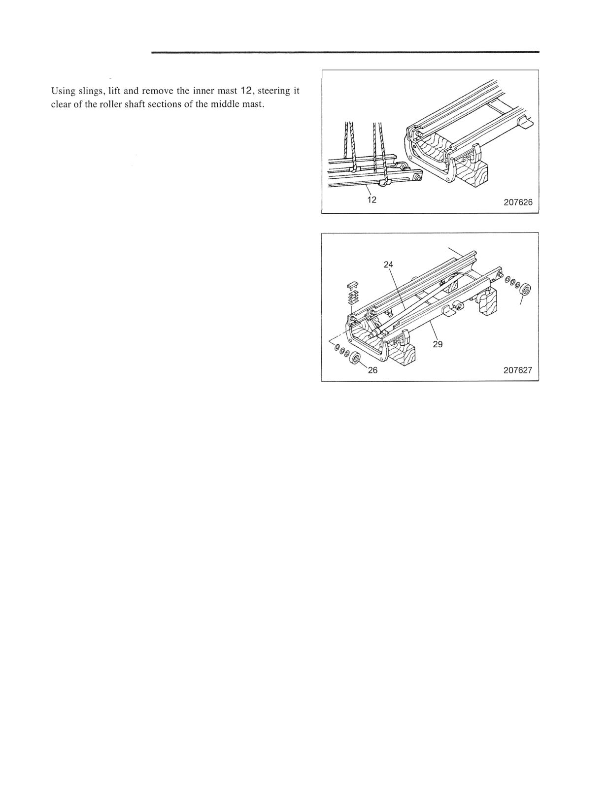
MAST AND FORKS
3. Removing inner mast 12
4. Removing main rollers 26, 27 from middle mast 28
28
and outer mast 29
Remove the bolts that are holding second lift cylinders 24.
Place the cylinder rod ends on the outer mast. Lower
middle mast 28 until main rollers 26, 27 can be removed.
Then, remove the main rollers.
27
Inspection after disassembly
Follow the same inspection procedure as for the simplex
mast. Refer to page 12-13.
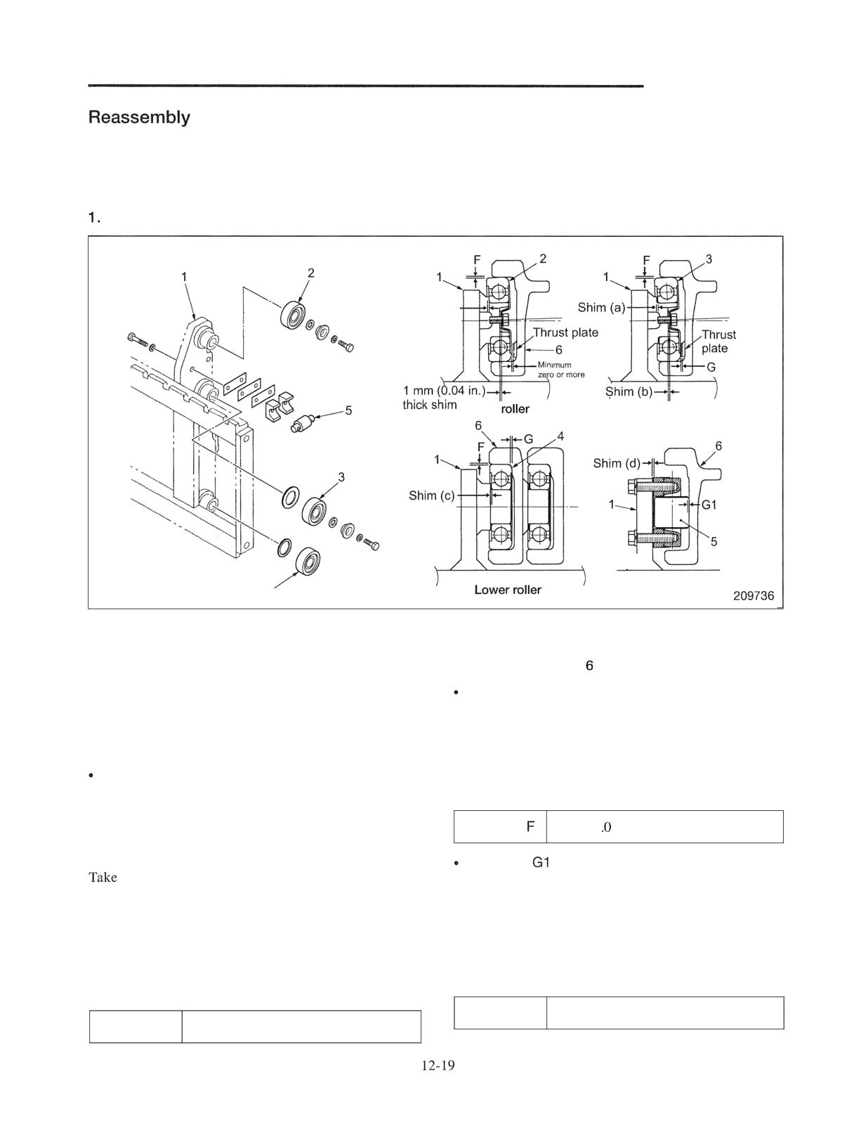
MAST AND FORKS
Follow the disassembly sequence in reverse. Be careful
with the followings .
Suggestions for Reassembly
Installing lift bracket rollers (all mast models)
No shim required
clearance
Upper
Middle roller
4
Side roller
Sequence
1 Lift bracket
3 Lift bracket middle rollers
5 Side rollers
2 Lift bracket upper rollers
4 Lift bracket lower rollers
Inner mast
The lift bracket has three main roller bearings at one
Clearance F
side and a side roller at both sides as shown.
Clearance between roller circumference and inner mast
Clearances F and G must be maintained between these
thrust surface (back-to-front play):
rollers and thrust surface of the inner mast for smooth
Clearance F is used for determining the proper size of
operation.
the rollers.
Select appropriate diameter rollers so that the clearance
Clearance G
meets the specification. Make sure the rollers rotate
Clearance between roller side surface and inner mast
smoothly when installed.
thrust surface (right-to-left-play).
Clearance G is used for determining the correct amount
Clearance
1 mm (0.04 in.) or less
of shims at the bearing seat.
Move lift bracket to the top of the inner mast and press
the bracket to either the left most or rightmost position.
Clearance
measurements of clearance G between the side
Clearance between side roller circumference and inner
surface of roller and inner mast.
mast side roller thrust surface:
Move side roller to the upper end of the inner mast and
Note: It is not necessary to adjust the lift bracket upper
press the lift bracket to either the left most or rightmost
roller with shims.
position.
Take measurement of clearance GI between the roller
Adjust the clearance to the specification with shims (a)
circumference and inner mast.
and (b) for middle roller and with shim (d) for the lower
Adjust the clearance with shims to the specification.
roller.
Clearance GI
0.1 to 0.5 mm (0.004 to 0.020 in.)
Clearance G
0.1 to 0.5 mm (0.004 to 0.020 in.)
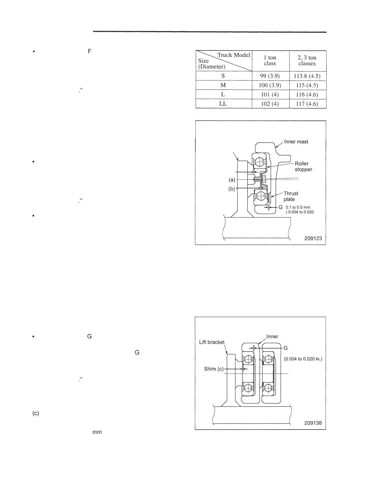
MAST AND FORKS
(1) Choosing correct roller diameters
Unit : mm (in.)
Measure clearance for upper rollers 2, middle rollers 3
and lower rollers 4. If the measured clearances do not
conform to the standard values, replace with rollers of
correct diameters listed in the table to the right.
Note: For measuring procedures, refer to "Inspection and
Adjustment
The rollers installed should rotate smoothly.
(2) Adjusting clearance G between the middle roller and
Lift bracket middle roller
thrust plate
Note: The following adjustment is not required for the
upper roller.
Lift bracket
Measure clearance G between the middle roller and
thrust plate. If the measured clearance does not conform
to the standard value, adjust clearance G in the manner
Shim
described below.
Shim
Note: For measuring procedures, refer to "Inspection and
Adjustment
in.)
Adjustment
If clearance G is excessive, increase the thickness of shims
(a) as required. Increase the thickness of shims (b) by the
same amount that are added to shims (a).
Shim (a) is available in two sizes: 1 mm (0.04 in.) and 0.5
mm (0.020 in.). Shim (b) is available in only one size, 1
mm (0.04 in .).
If shims (a) are increased by 0.5 mm (0.020 in.), shims (b)
do not need to be increased by the equal amount.
Remarks: At the assembly plant, shims (a) are usually
adjusted to 1 mm (0.04 in.) and shims (b) to 2.0
mm (0.08 in.) for the shipment.
(3) Adjusting clearance G between lower rollers and inner
Lift bracket lower roller
mast
Measure clearance between the lower rollers and inner
mast
mast. If the measured clearance does not conform to the
standard value, adjust clearance
in the manner
0.1 to 0.5 mm
described below.
Note: For measuring procedures, refer to "Inspection and
Adjustment
Adjustment
If clearance G is excessive, increase the thickness of shims
as required.
Remarks: At the assembly plant, shims (c) are usually
adjusted to 1
(0.04 in.) for the shipment.
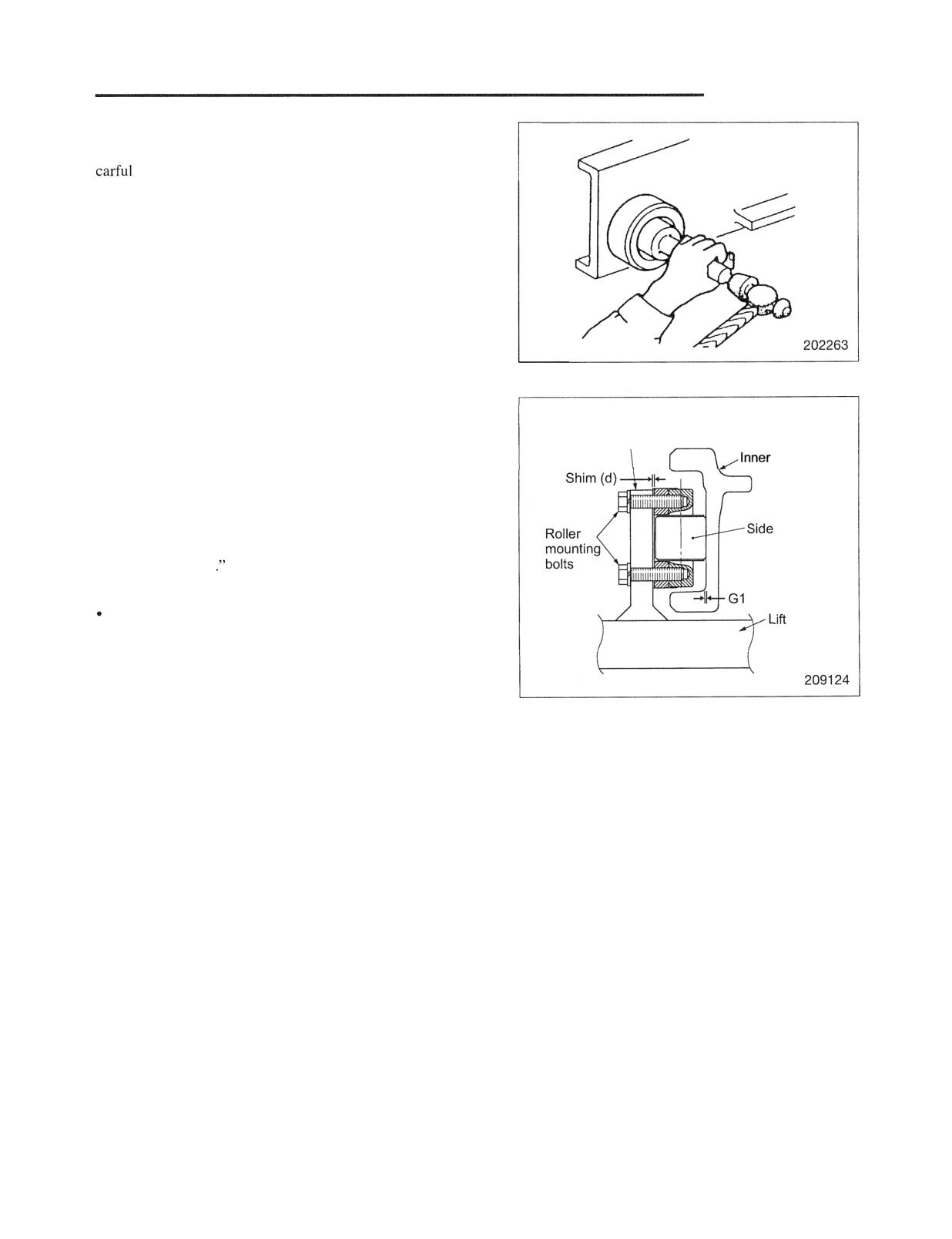
MAST AND FORKS
(4) Installing main rollers
To install main rollers on shafts, use a driving tool. Be
not to strike the outer roller surface with the driving
tool.
The side of the roller with larger chamfering must face
toward the outside.
Make sure the rollers rotate smoothly when installed.
(5) Adjusting clearance GI between the side roller and
inner mast
Lift bracket
Measure clearance GI between the side roller's rolling
mast
contact surface and inner mast. If the measured clearance
does not conform to the standard value, adjust clearance
GI in the manner described below.
roller
Note: For measuring procedures, refer to "Inspection and
Adjustment
Adjustment
bracket
If clearance G I is excessive, increase the thickness of
shims (d) as required.
Remarks: At the assembly plant, shims (d) are usually
adjusted to 1 mm (0.04 in.) for the shipment.