Cat Lift Trucks. For use with K21/K25 and S4S Engine Service Manuals (2007) - page 2
TRANSMISSION
Disassembly and Reassembly of Other Components
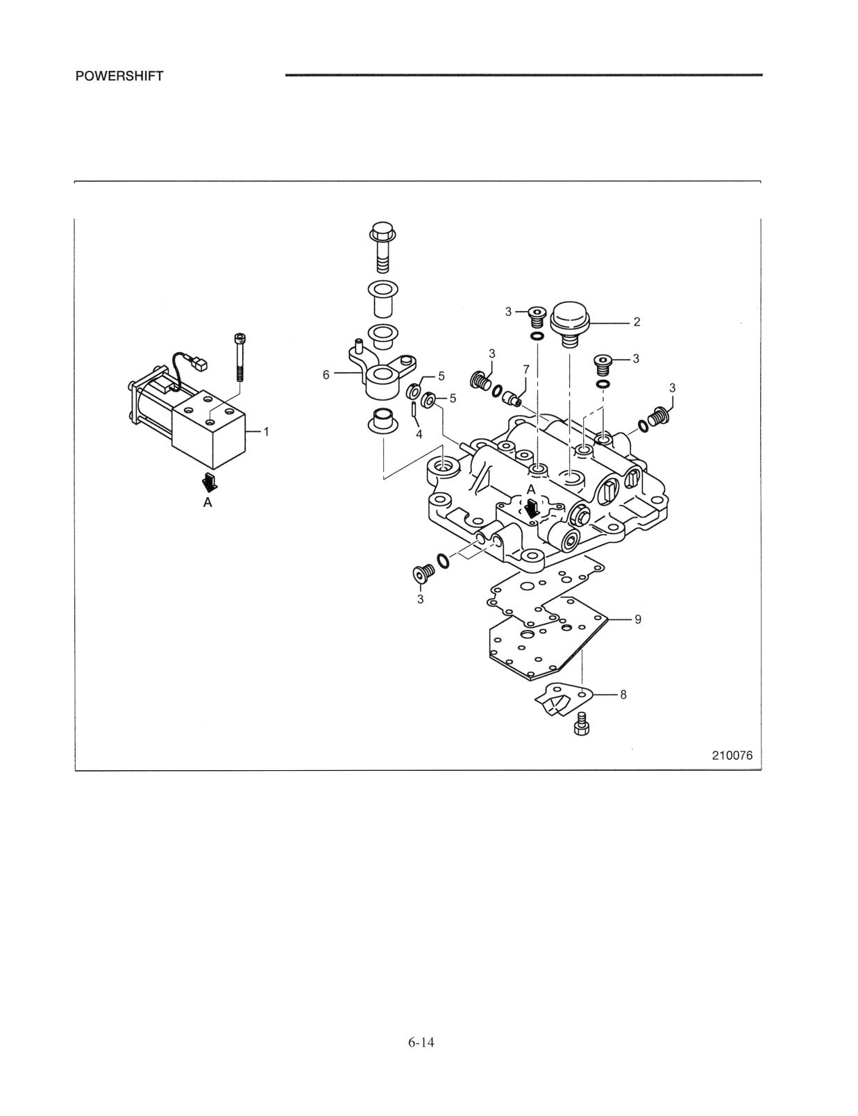
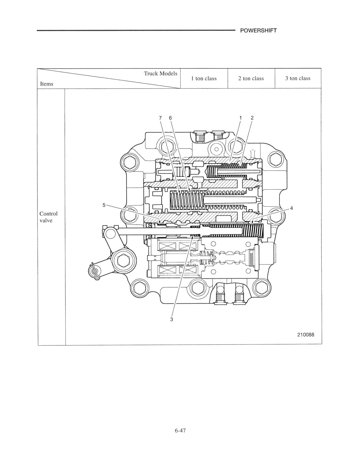
Control Valve
Disassembly (Part 1)
Sequence
1 Solenoid valve
6 lnching lever, Retainer, Bushing
2 Breather
7 Main orifice
3 Plug, O-ring
8 Breather cover
4 Spring pin
9 Valve plate, Gasket
5 Inching rod plates
When loosening plug 3, tap the plug head once or twice to
make the work easier.
TRANSMISSION
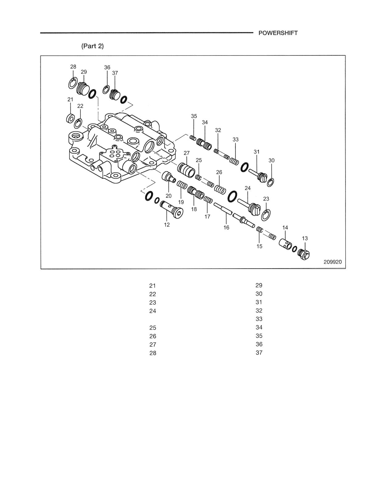
Disassembly
Sequence
12 Strainer, O-ring
Oil seal
Accumulator plug, O-ring
13 lnching plug, O-ring
Snap ring
Snap ring
14 lnching stopper
Snap ring
Main spring seat, O-ring
15 lnching return spring
Accumulator spring seat,
Main relief spring (thin)
16 lnching rod
O-ring
Main relief spring (thick)
17 lnching valve spring
Inner spring
Regulator valve
18 lnching valve
Outer spring
Slug
19 Return spring
Accumulator piston
Snap ring
20 lnching sleeve
Snap ring
Main relief plug
inspection after Disassembly
(1) Valve housing
(3) Springs
(a) Check all oil holes for clogging.
(a) Check for fatigue and damage
(2) Valves
(4) Oil seal
(a) Check for wear or damage. Make sure the
(a) Check the lip for damage.
sliding surfaces are smooth.
(b) Check the small holes for clogging
TRANSMISSION
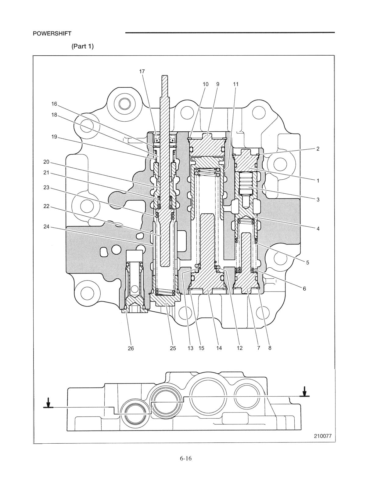
Reassembly
TRANSMISSION
Main relief plug
Accumulator spring seat, O-ring
Snap ring
Snap ring
Slug
Snap ring
Regulator valve
Oil seal
Main relief spring (thick)
lnching sleeve
Main relief spring (thin)
Return spring
Main spring seat, O-ring
lnching valve
Snap ring
lnching valve spring
Accumulator plug, O-ring
lnching rod
Snap ring
lnching return spring
Accumulator piston
lnching stopper
Outer spring
lnching plug, O-ring
Inner spring
Strainer, O-ring
Suggestions for Reassembly
(1) Cleaning oil passages
(a) The oil passages in the valve housing must be
cleaned thoroughly. Make sure there is no
clogging in any passage before reassembling the
control valve.
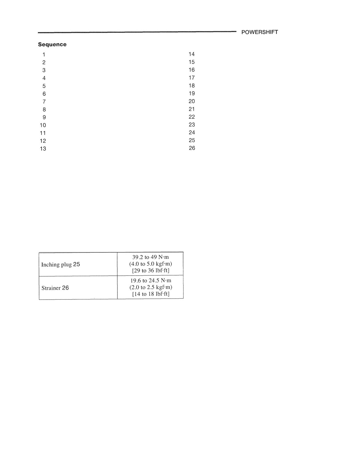
(2) Tightening torques
(a) Tighten the following parts to the specified
torques.
TRANSMISSION
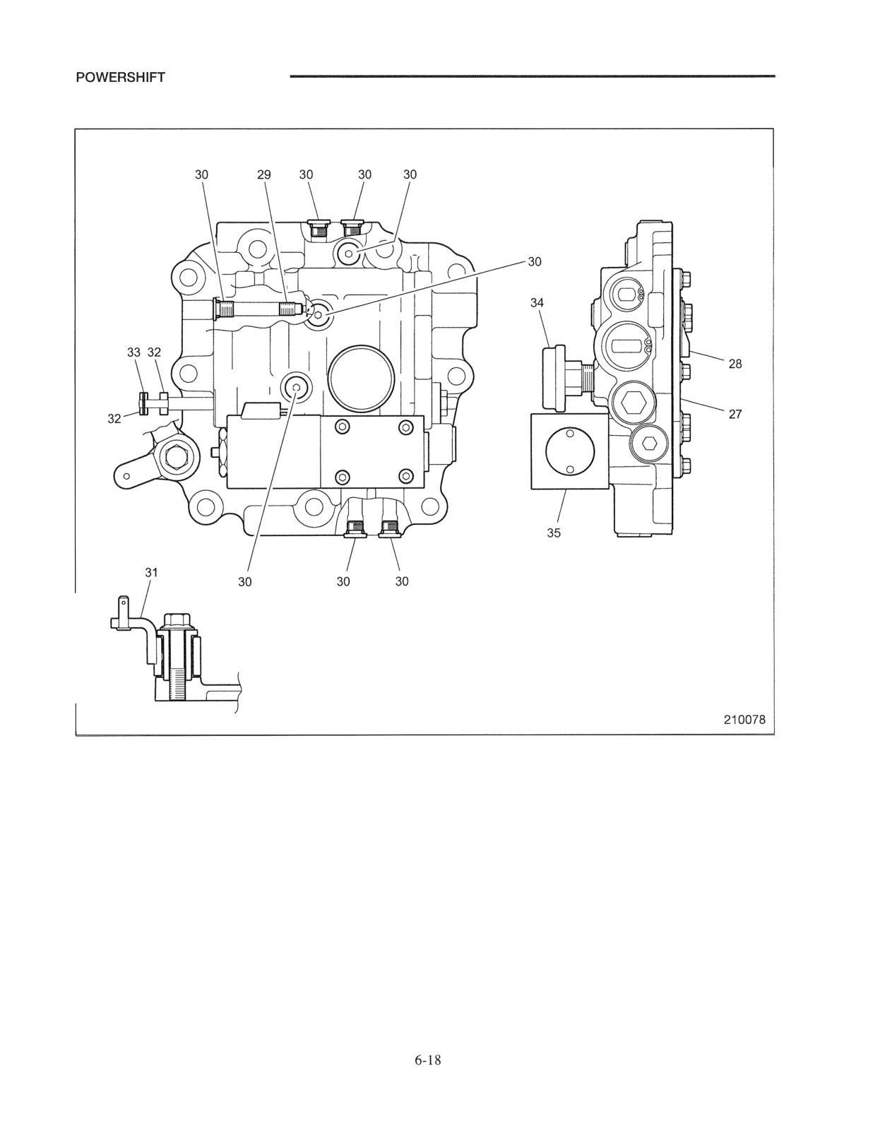
Reassembly (Part 2)
Sequence
27 Valve plate, Gasket
32 lnching rod plate
28 Breather cover
33 Spring pin
29 Main orifice
34 Breather
30 Plug, O-ring
35 Solenoid valve
31 lnching lever, Retainer, Bushing
TRANSMISSION
Suggestions for Reassembly
(1) Tightening torques
(a) Tighten the following parts to the specified
torques.
Bolts fastening valve plate 27
6.0 to 8.0
(0.6 to 0.8
to 5.9
Plug 30
35.3 to 43.1
Bolt for installing inching
(3.6 to 4.4
lever 31
[26 to 32
6.0 to 8.0
Plug 35
(0.6 to 0.8
Bolt for installing solenoid
to 5.9
valve 37
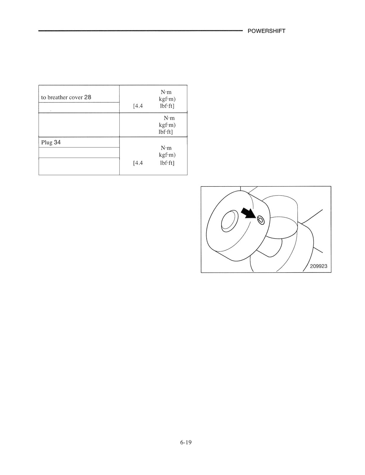
(2) Direction of spring pin slit
(a) The spring pin 33 should be installed with its slit
toward the end of the inching shaft.
TRANSMISSION
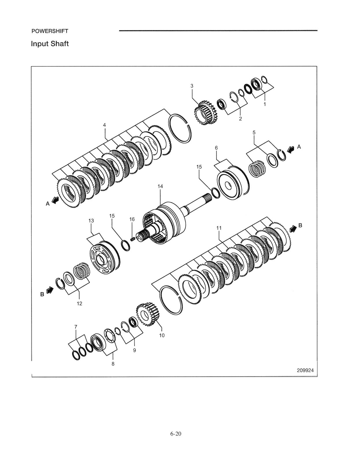
Assembly
Disassembly
TRANSMISSION
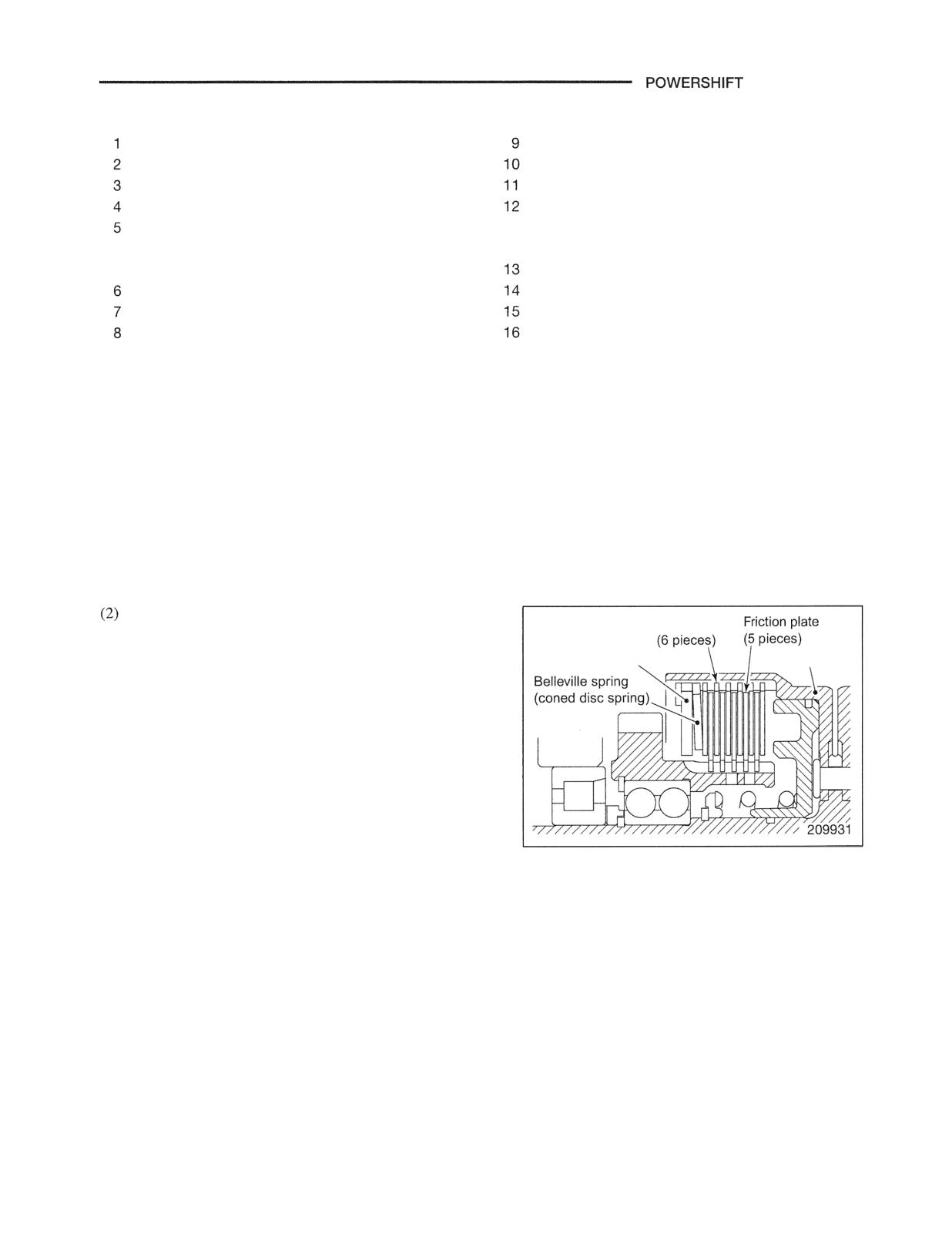
Sequence
Ball bearing, Sealing ring, Spacer
Angular ball bearing, Snap ring (2 pieces)
Angular ball bearing, Snap ring (2 pieces)
Forward gear
Reverse gear
Pressure plate, Belleville spring (coned disc
Pressure plate, Belleville spring (coned disc
spring), Mating plate (6 pieces), Friction plate
spring), Mating plate (6 pieces), Friction plate
(5 pieces), Snap ring
(5 pieces), Snap ring
Clutch spring, Snap ring, Spring retainer
Clutch spring, Snap ring, Spring retainer
Clutch piston, Piston ring
Clutch piston, Piston ring
lnput shaft assembly
Sealing ring (3 pieces)
Seal ring
Roller bearing, lnput shaft spacer
Set screw (2 pieces)
Suggestions for Disassembly
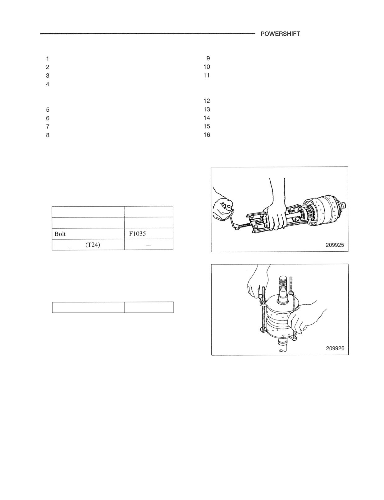
(1) Removing input shaft ball bearing
(a) Use the special tools to remove the ball bearing
from the input shaft.
Special tool needed
Puller
91268 - 13810
Plate
91268 - 13820
- 10020
Gear puller
(2) Disassembling input shaft
(a) With the clutch spring compressed using the
special tool or a press, remove the snap ring.
Special tool needed
Piston tool
91268 - 17100
POWERSHIFT TRANSMISSION
Inspection after Disassembly
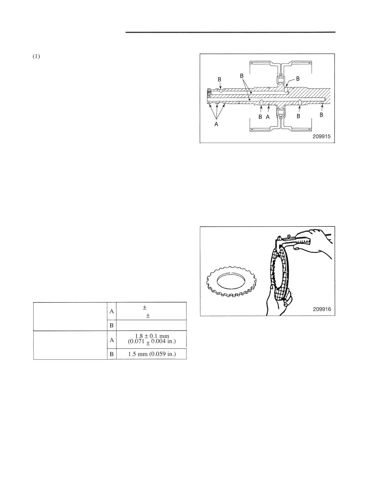
Input shaft
(a) Check splines for wear or other damage.
(b) Check the seal rings A and their grooves for wear
or damage, and measure the width of each groove.
(c) Check the oil passages B for clogging.
(d) Check the clutch drum and input shaft for
looseness.
(2) Gear
(a) Check gear and splines for wear or damage.
(3) Drum
(a) Check the plate sliding surfaces for wear or other
damage.
(b) Check the clutch piston sliding surfaces for wear or
other damage.
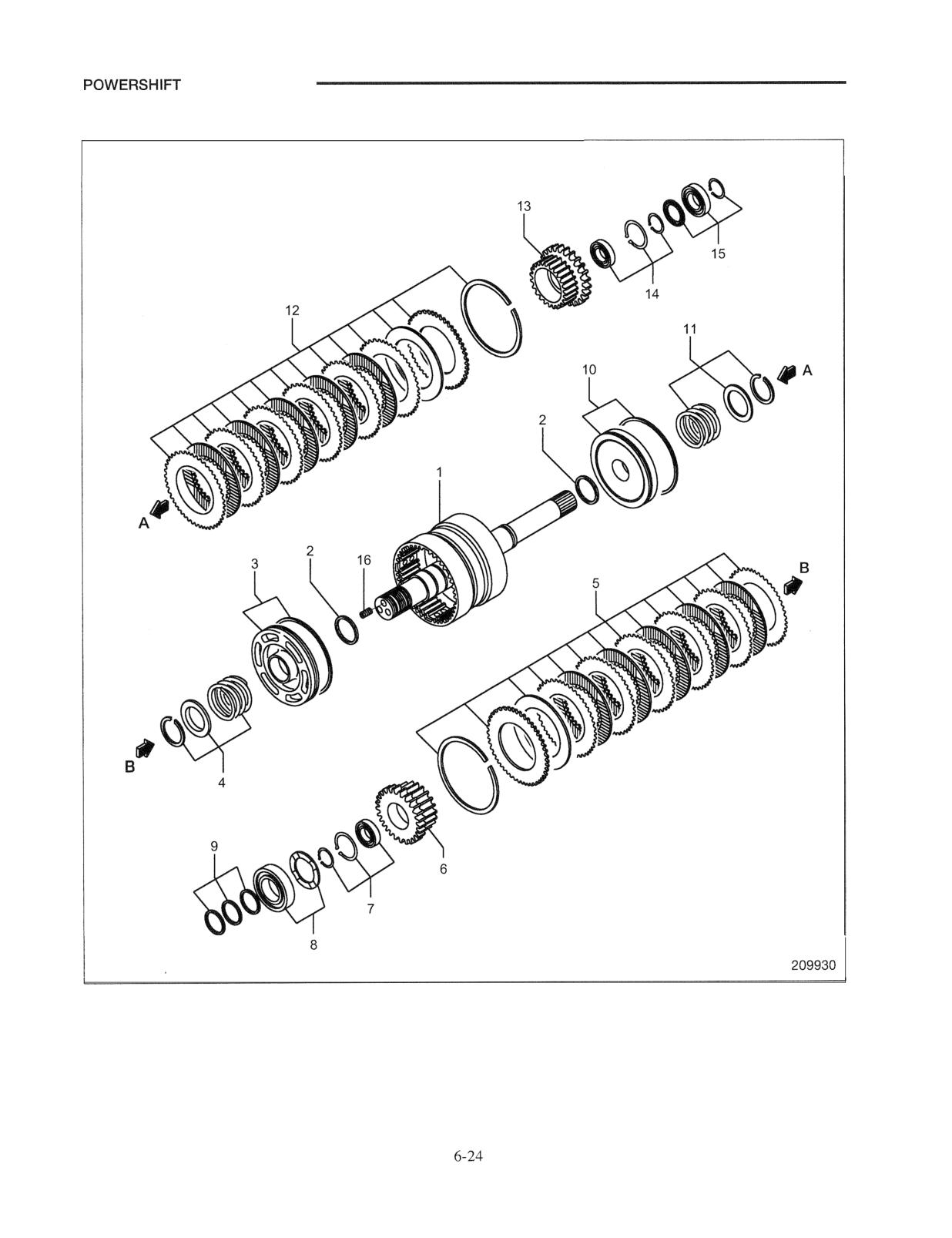
(4) Friction plates and mating plates
(a) Check for burns, trace of uneven contact,
deformation and wear.
(b) Check splines for wear or other damage.
(5) Piston ring
Check piston ring for wear or damage.
A: Standard value B: Repair or service limit
2.6
0.10 mm
Thickness of friction plate
(0.102
0.004 in.)
2.2 mm (0.087 in.)
Thickness of mating plate
TRANSMISSION
Reassembly
TRANSMISSION
Sequence
Input shaft assembly
Seal ring (3 pieces)
Seal ring
Clutch piston, Piston ring
Clutch piston, Piston ring
Clutch spring, Snap ring, Spring retainer
Clutch spring, Snap ring, Spring retainer
Pressure plate, Belleville spring (coned disc
Pressure plate, Belleville spring (coned disc
spring), Mating plate (6 pieces), Friction plate
spring), Mating plate (6 pieces), Friction plate
(5 pieces), Snap ring
(5 pieces), Snap ring
Reverse gear
Forward gear
Angular ball bearing, Snap ring (2 pieces)
Angular ball bearing, Snap ring (2 pieces)
Bearing, Snap ring, Spacer
Roller bearing, Spacer
Set screw (2 pieces)
Suggestions for Reassembly
(1) Assembling clutch piston
(a) Install seal rings on the input shaft and apply a thin
coat of ATF on the sliding surfaces of the clutch
piston. Take care not to damage or bend the rings.
(b) Install the piston ring on the clutch piston, and
apply a thin coat of ATF.
(c) Install the clutch piston onto the input shaft, being
careful not to damage any of the parts.
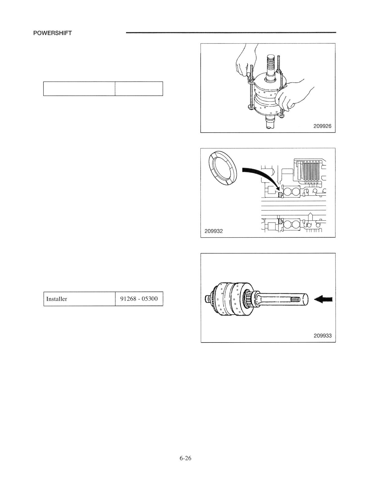
Assembling plates
Pressure plate Mating plate
(a) When replacing the friction plates, also replace the
mating plates.
(I piece) \
Drum
(b) Follow the reassembly sequence carefully. Do not
install a wrong number of plates.
(c) Apply ATF to each mating plate and friction plate
before installing them.
(d) Install the Belleville spring (coned disc spring)
with its convex side facing the mating plate.
TRANSMISSION
(3) Installing snap rings
(a) Install the snap rings with the clutch spring
compressed using the special tool or a press.
Special tool needed
Piston tool
91268 - 17100
(4) Installing spacer
(a) Install the spacer with the oil grooves facing the
ball bearing.
(5) Installing bearing
(a) Drive the ball bearing into position on the input
shaft the using special tool.
Special tool needed
TRANSMISSION
(6) Installing set screw
(a) Apply Loctite to the set screws before installing
(7) Testing clutch piston operation
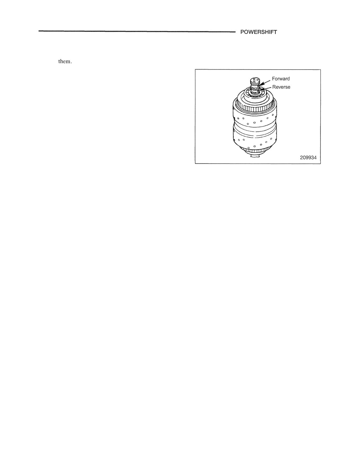
gear oil hole
(a) Check that the clutch piston operates correctly by
gear oil hole
applying compressed air pressure through the
forward (reverse) gear oil hole.
Note: Always use filtered, clean compressed air.
Forward
gear
Reverse
gear
TRANSMISSION
Oil Pump Assembly
Disassembly
Sequence
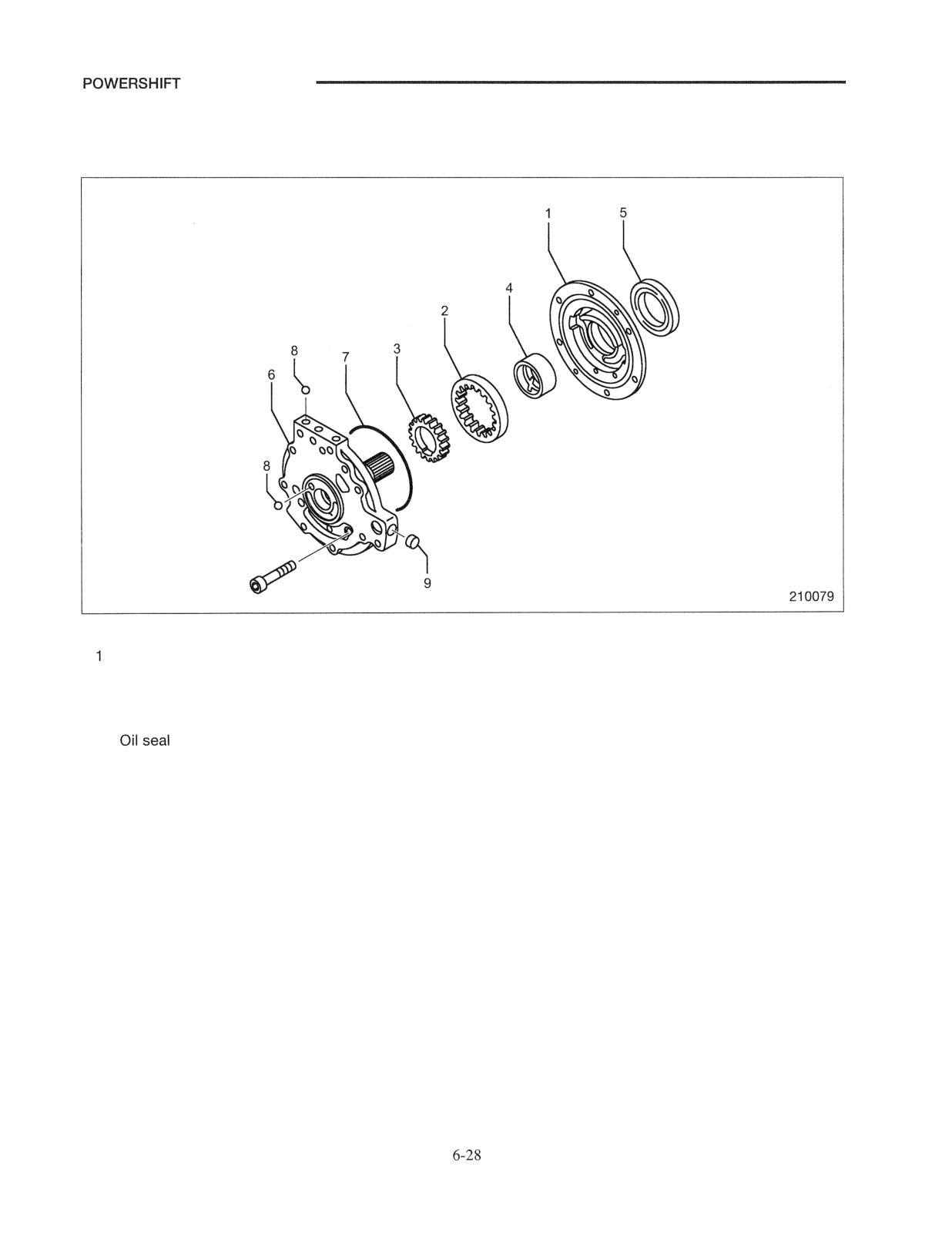
Oil pump body
6 Stator shaft assembly
2 Internal gear
7 O-ring
3 Oil pump drive gear
8 Steel ball
4 Bushing
9 Sealing cup
5
Suggestion for Disassembly
Note: Inspect the oil seal in the oil pump body. Do not
remove the oil seal unless defects are spotted during
inspection.
Reassembly
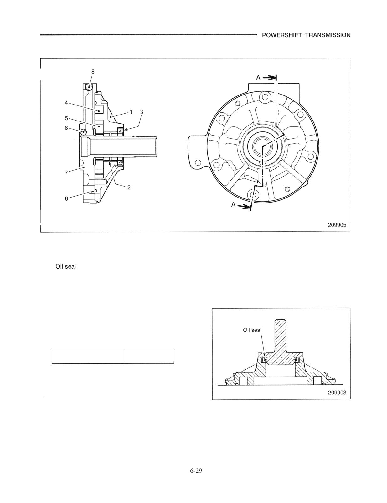
View A - A
Sequence
1 Oil pump body
5 Oil pump drive gear
2 Bushing
6 O-ring
3
7 Stator shaft assembly
4 Internal gear
8 Steel ball
Suggestions for Reassembly
(1) Installing oil seal
(a) Press fit the oil seal into the pump body using the
special tool.
Special tool needed
Installer
91268 - 15300
(b) Apply grease to the oil seal lip.
"TRANSMISSION
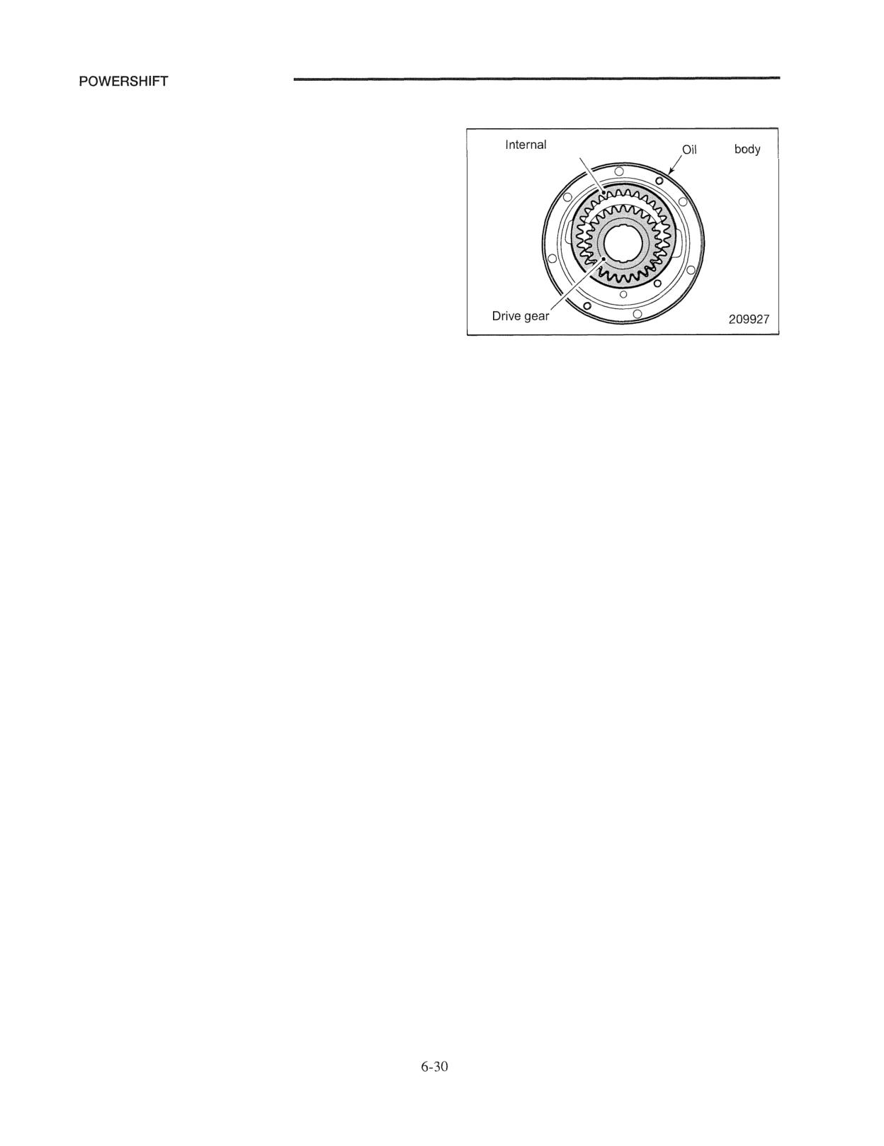
(2) Lubricating internal parts
(a) Apply ATF to the internal gear, drive gear and the
gear
pump
inside surfaces of the oil pump body before
reassembling them.
(3) Operation check
(a) Turn the drive gear of the reassembled oil pump
assembly with your fingers to check that it turns
smoothly.
Inspection and Adjustment
Oil Pressure Measurement
(1) Transmission oil level check
(a) Check the transmission fluid level with the level
gauge.
(b) Start and run the engine at an idling speed for
about 3 minutes, and then stop the engine.
(c) Wait for about 30 second after stopping the engine,
and check the level.
(d) The checking procedure must bc completed within
5 minutes after the engine has stopped.
(2)
Engine warm-up
(a) Warm up the engine to raise the temperature of the
transmission oil.
(3)
Engine speed measurement
(a) After the engine is warmed up, measure the idling
speed and maximum no-load speed according to
the engine service manual. Make the necessary
adjustments if either or both of the speeds do not
meet the specifications.
(4)
Preparation for oil pressure measurement
(a) Stop the engine after checking and adjusting the
engine speeds.
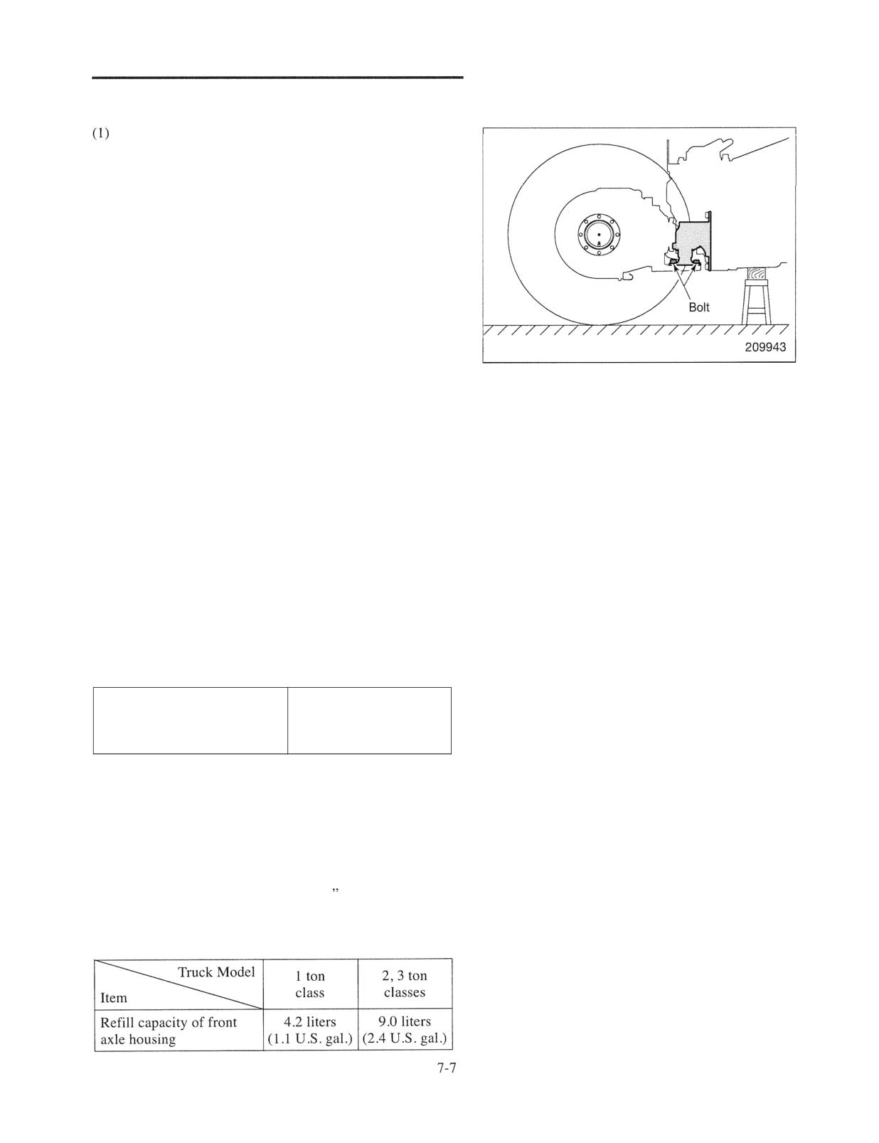
(b) Raise the front wheels completely clear of the
ground either by jacking up the front axle housing
or placing a wood block under the outer mast and
tilting the
forward.
(c) Block the rear wheels.
Note: The front wheels turn during the clutch pressure
measurement. Be careful and stay away from
the wheels.
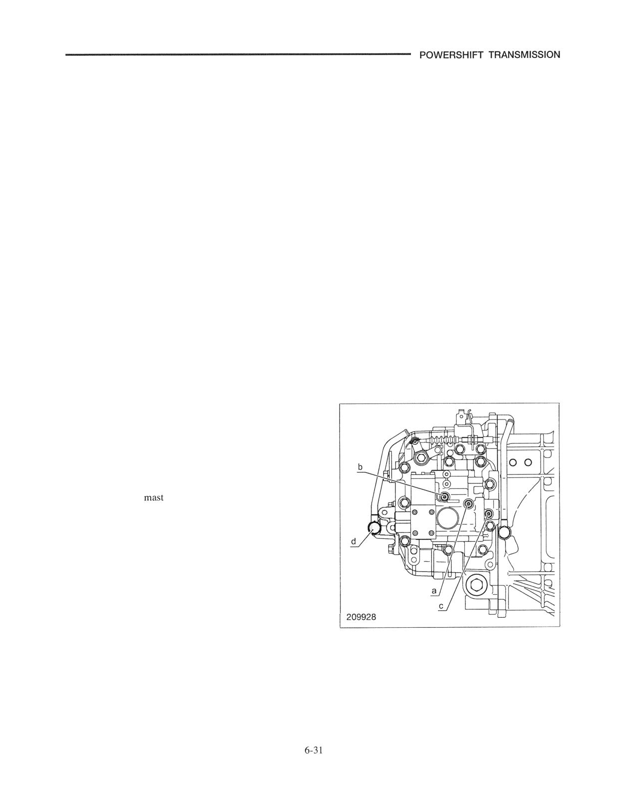
(d) Connect the oil pressure gauge to each of the oil
pressure taps indicated in the illustration.
a: Main pressure
b: Clutch pressure
c: Torque converter inlet pressure
d: Lubrication oil pressure
Note: When loosening the plugs a through d, tap the
plug head once or twice to make the work easier.
TRANSMISSION
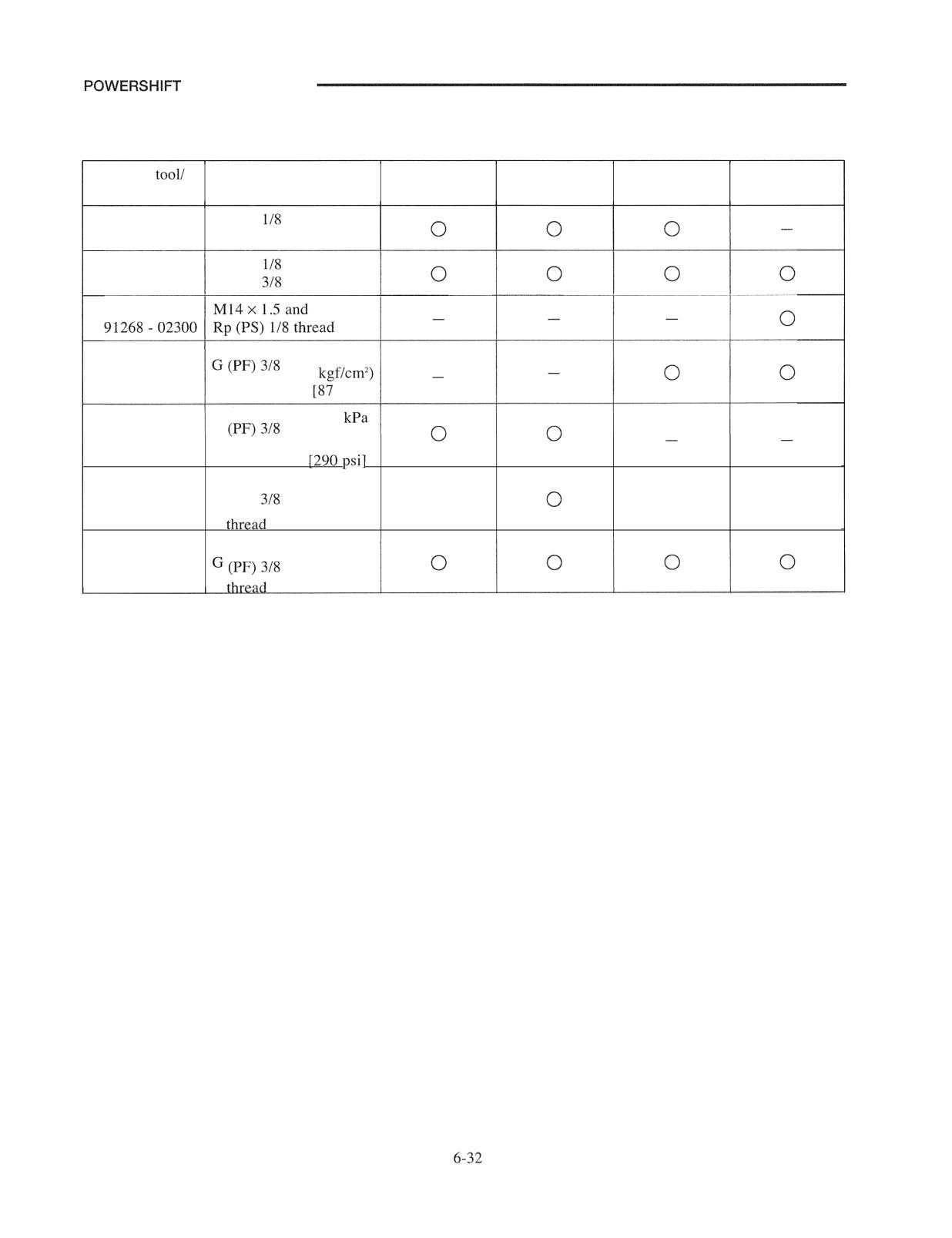
(e) Use the following tools for the oil pressure measurements.
Oil pressure measurement tools
Special
Torque converter
Lubrication oil
Remarks
Main pressure
Clutch pressure
part number
inlet pressure
pressure
*Connector
G (PF)
and
65628 - 00400
Rc (PT) 118 thread
*Connector
R (PT)
and
64309 - 17733
G (PF)
thread
Connector
600 kpa
*Gauge
(6
64309 - 17714
thread
psi]
2000
*Gauge
(20 kgflcm2)
64309 - 17713
thread
Both side
*Hose
G (PF)
0
0
0
64309 - 17722
Both side
*Connector
For gauge
64309 - 17731
connection
Note: Tools marked with (*) are included in the gauge kit 64309 - 17701.
TRANSMISSION
(5)
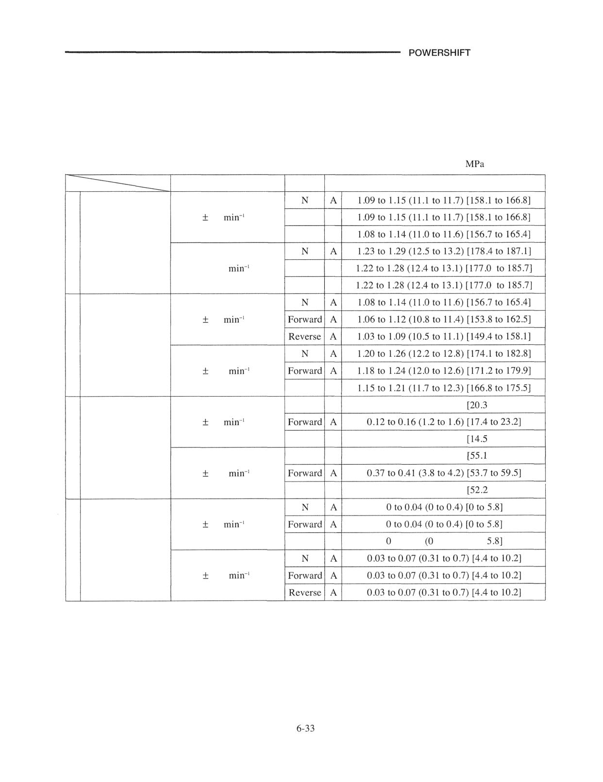
Oil pressure measurement procedure
(a) Start the engine, shift the direction lever into the neutral position and measure the main pressure, torque
converter inlet pressure, and lubrication oil pressure.
(b) Measure the clutch pressure with the lever shifted into the forward position, then measure it again with the
lever in the reverse position.
A: Standard value
Unit:
(kgf/cm2) [psi]
Engine rprn
Shift
Oil pressure
800
50
(rprn)
Forward
A
Reverse
A
a
Main pressure
1600 It 100
(rprn)
Forward
A
Reverse
A
800
50
(rpm)
b
Clutch pressure
1600
100
(rprn)
Reverse
A
N
A
0.14 to 0.18 (1.4 to 1.8)
to 26.11
800
50
(rprn)
Reverse
A
0.10 to 0.14 (1.0 to 1.4)
to 20.31
Torque converter
c
inlet pressure
N
A
0.38 to 0.42 (3.9 to 4.3)
to 60.91
1600
100
(rprn)
Reverse
A
0.36 to 0.40 (3.7 to 4.1)
to 58 .O]
800
50
(rprn)
Reverse
A
to 0.04 to 0.4) [0 to
Lubrication oil
pressure
1600
100
(rprn)
Clutch (Inching) Pedal Adjustment
Brake
209929
The clutch (inching) mechanism is linked to the brake
pedal. Depressing the brake pedal cuts the pressure acting
on the transmission before the brakes take effect, bringing
the transmission to a neutral condition.
A faulty inching mechanism may create such problems as
failure in clutch disengagement and partial clutch
engagement. This in turn may cause an abnormal increase
in the transmission temperature, as well as braking
malfunctions and clutch plate seizures. Be sure to make all
the following adjustments carefully so that these problems
be avoided.
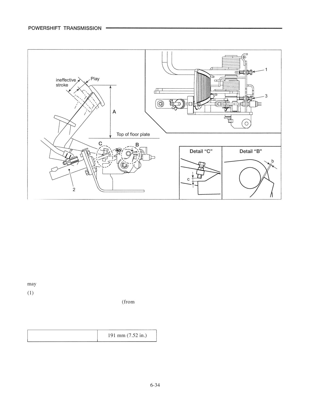
Adjusting brake pedal
(a) Adjust the brake pedal height A
the floor
plate top surface to the brake pedal top surface) to
the following standard value by turning the stopper
bolt 1 and then lock it with the lock nut.
Brake pedal height A
(b) Remove the clearance between the push rod pin of
the brake master cylinder 2 and the piston (zero
clearance).
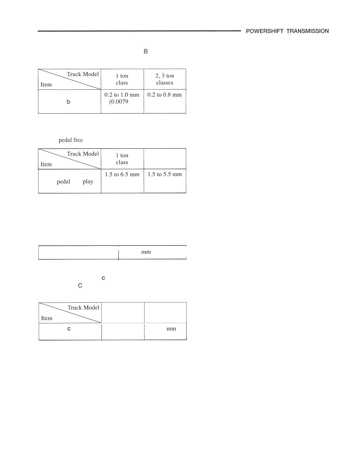
(c) Turn the push rod of the brake master cylinder
until the clearance b in the detail
adjusted to the
range indicated below.
Clearance
to
(0.0079 to
0.0394 in.)
0.0315 in.)
(d) Lock the clevis firmly with the lock nut.
(e) If the pedal has been properly adjusted, the brake
play becomes the range indicated below.
2,3 ton
classes
Brake
free
(0.0591 to
(0.0591 to
0.2559 in.)
0.2165 in.)
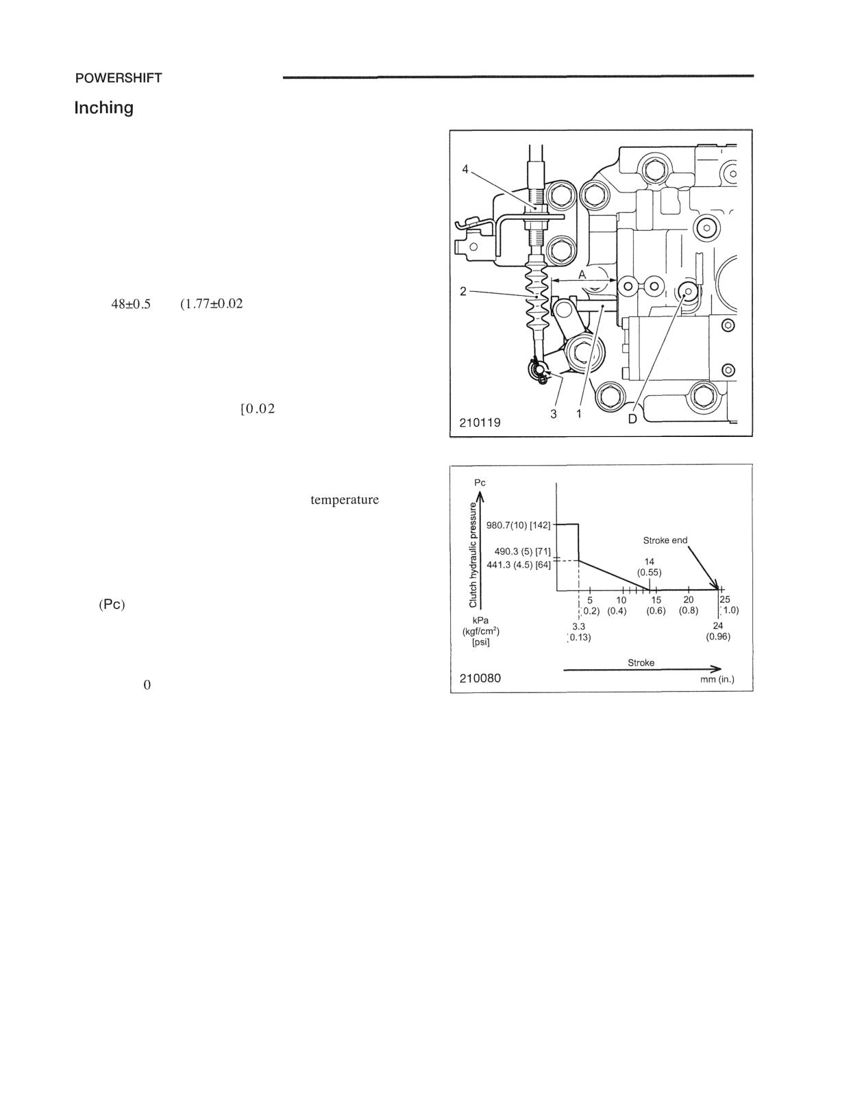
(2) Adjusting inching pedal
(a) Adjust the height A of the inching pedal (from the
floor plate top surface to the inching pedal top
surface) to the following standard value with the
stopper bolt 3.
Inching pedal height A
191
(7.52 in.)
I
(b) Adjust the clearance between the bolt and linkage in
the portion to the following value and lock it firmly
with the nut.
1 ton
2,3 ton
class
classes
Clearance between
10.0 mm
11.6
bolt and linkage
(0.391 in.)
(0.457 in.)
TRANSMISSION
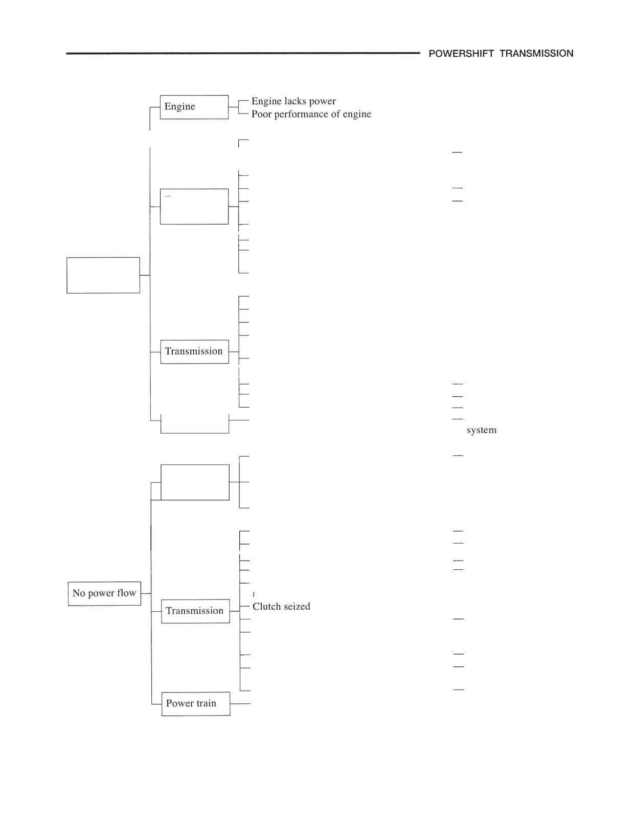
Valve Adjustment
Start by:
(a) Blocking the rear wheels, then raising the front wheels
following the procedure described in the preceding oil
pressure measurement section;
(b) Connecting an oil pressure gauge to the oil pressure tap
(position D in the illustration);
(c) Confirm that the inching rod 1 projects completely.
The projection A of the inching rod (initial condition)
is
mm
in.)
(d) Connect the inching cable 2 to the inching lever pin 3.
(e) Adjust the play of the inching cable to 0.5 to 1.5 mm
(0.02 to 0.060 in.) and secure the cable by inching
cable locking nut (outer) 4. Be sure to observe the
lower limit (0.5 mm
in.]) to prevent over
tensioning of the cable.
Procedure
(a) Run the engine at idle to raise the
of the
transmission oil.
(b) Shift the lever into the forward (reverse) position.
(c) Depress the inching pedal gradually to make the
plunger 2 retract, while recording the clutch pressure
for each stroke distance of plunger 2 in order to
know the relationship between them.
(d) Check that the recorded values correspond to the
values in the fig. on the right. The oil pressure must be
exactly (zero) when the plunger 2 is fully retracted.
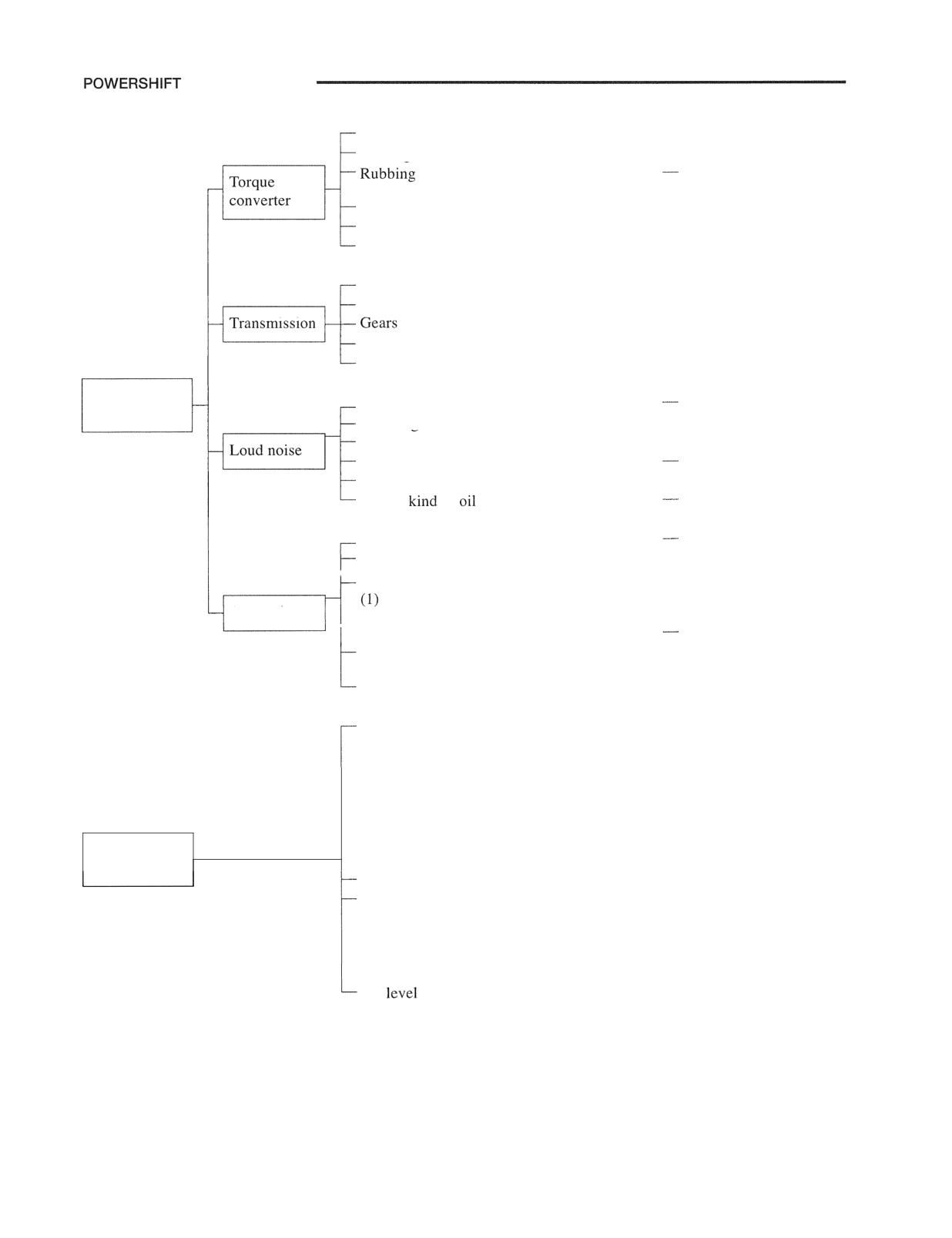
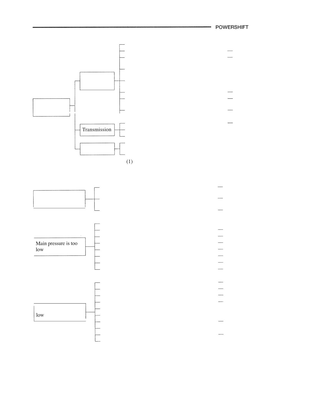
Troubleshooting
-
Tune up engine.
-
Tune up engine.
Oil level too low
-
Refill.
I
Air being sucked in on suction side
Replace gasket and
retighten.
t
Faulty action of spool in main regulator valve
-
Repair or replace.
Weakened spring in main regulator valve
Replace.
Torque
Worn gears in oil pump, resulting in
Overhaul and check or
converter
reduced capacity
replace defective parts
Magnet strainer clogged
-
Clean or replace.
Seal rings or O-rings worn
-
Replace.
Stator freewheel seized
-
Replace torque converter
assembly.
Not enough
Impeller damaged or rubbing
-
Replace torque converter
output power
assembly.
Air being sucked in on suction side
-
Retighten or replace
Water in oil
-
Replace oil.
Oil level too low
-
Refill.
Pedal linkage maladjusted (brake shift and
-
Readjust.
forward reverse)
Main pressure too low, resulting in slipping
-
Readjust.
clutches
Seal rings or O-rings worn
Replace.
Clutch piston damaged
Replace.
,
Friction plate seized or dragging
Replace.
Road wheels
High mechanical resistance in road wheels
Check and adjust brake
Flexible plate broken
Replace.
- Not enough oil
-
Refill.
Torque
Oil pump drive defective
-
Replace.
converter
- Turbine shaft broken
-
Replace.
Main pressure too low
-
Check pump gears for
wear or replace.
Not enough oil
Refill.
Inching pedal link maladjusted
Readjust.
Seal ring worn in servo case
Replace.
O-rings on input shaft worn
Replace.
Plug on input shaft loose or slipped off,
-
Repair.
resulting in oil leaks
-
Replace.
Shafts broken
Replace.
-
Clutch drum, particularly snap ring groove,
Replace.
defective
Snap ring fitted to clutch drum broken
Replace
Oil way for supplying oil pressure to clutch
Clean or replace.
piston clogged
Shaft splines worn
Replace shafts.
ront axpearts in reduction differential or
-
Repair or replace.
TRANSMISSION
Flexible plate broken
-
Replace.
Bearings damaged
-
Replace,
blades of running member
Replace.torque
converter.
Bolts loose
-
Retighten or replace.
Splines worn
-
Replace.
Oil pump noisy
-
Repair or replace.
Friction plates seized and dragging
-
Replace friction plate.
Bearings worn or seized
-
Replace.
broken
-
Replace.
Bolts loose
-
Retighten or replace.
Splines worn
-
Replace.
Abnormal
Clean or replace.
Magnet strainer clogged
noise
Main regulator valve defective
-
Wash or replace.
Restriction in oil pipe
-
Replace.
Oil too viscous in cold weather
Replace oil.
Instruments faulty
-
Replace.
Wrong
of
used
Replace oil.
Clean or replace.
Magnet strainer clogged
Oil pump defective
-
Replace,
Excessive oil leaks
Main regulator valve spring broken or
-
Replace.
Low noise
fatigued
(2) Main regulator valve spool defective
Repair or replace.
Air being sucked in
-
Retighten or replace
packing.
Oil level too low
-
Refill.
Leaking oil seals
- - Check lips and sliding
surfaces for wear.
Replace seals.
-
Leaking joint of case
- Retighten or replace
packing.
-
Leaking pipe connection or joint
-
Repair or replace pipe,
gasket and O-rings.
- Leaking drain plug
- Retighten and replace
Oil leaks
gasket.
Cracks or blowholes in case
- Replace.
Oil blowing out of transmission housing
(1) Water in oil
- Replace oil.
(2) Air being sucked in suction side
- Replace packing and
retighten.
(3) Oil leaks from air breather
- Repair.
Oil
too high
- Lower oil level.
TRANSMISSION
Oil level too high or too low
- Refill or drain.
Magnet strainer clogged
Clean or replace.
Impeller rubbing
Replace torque converter
assembly.
Stator freewheel defective
- Replace torque converter
assembly.
Torque
Air being sucked in
- Retighten or replace
converter
O-ring.
Water in oil
Replace oil.
Restriction in oil pipe (resulting in reduced
Repair or replace.
Oil temperature
circulation flow)
is too high
Bearings worn or seized
Repair or replace.
Instruments out of order
- Replace.
Friction plates dragging
Replace friction plates.
Bearings worn or seized
- Repair or replace.
Control linkage defective
- Repair or replace.
Truck not operated properly
- Urge user to operate
Others
properly.
Others
Cooling fan belt damaged
- Replace.
(2) Oil cooler clogged
- Clean or replace.
(3) Brakes grabbing
- Check and readjust.
Main regulator valve defective
Repair or replace valve
assembly.
Main pressure is too
Oil viscosity too high because of low temperature
Replace oil.
high
I
Wrong kind of oil used
Replace oil.
Magnet strainer clogged
- Clean or replace.
Oil pump failure
Replace.
Coil spring defective in main regulator valve
Replace.
Faulty movement of main regulator valve spool
Repair or replace.
Air being sucked in
Retighten or replace packing.
Not enough oil
Refill.
Control linkage defective
Repair or replace.
Clutch valve out of order
Repair or replace.
Magnet strainer clogged
Clean or replace.
Oil pump worn or otherwise defective
Replace.
Coil spring defective in main regulator valve
Replace.
Fautly movement of main regulator valve spool
Repair or replace.
I Clutch pressure is too
Air being sucked in
- Retighten or replace packing.
Not enough oil
- Refill.
Control linkage out of order
Repair or replace.
Inching valve defective
- Repair or replace.
Seal ring broken in servo case
Replace.
Clutch piston seal rings broken
- Replace.
TRANSMISSION
Lack of engine power if the speed is slightly low in
- Tune up engine.
both forward and reverse drive
Stall speed out of
Stator and freewheel damaged if the speed is
- Replace stator assembly.
specification
excessively low in both forward and reverse drive
Inching pedal linkage defective, or friction plates
- Repair or replace.
slipping if the speed is too high
TRANSMISSION
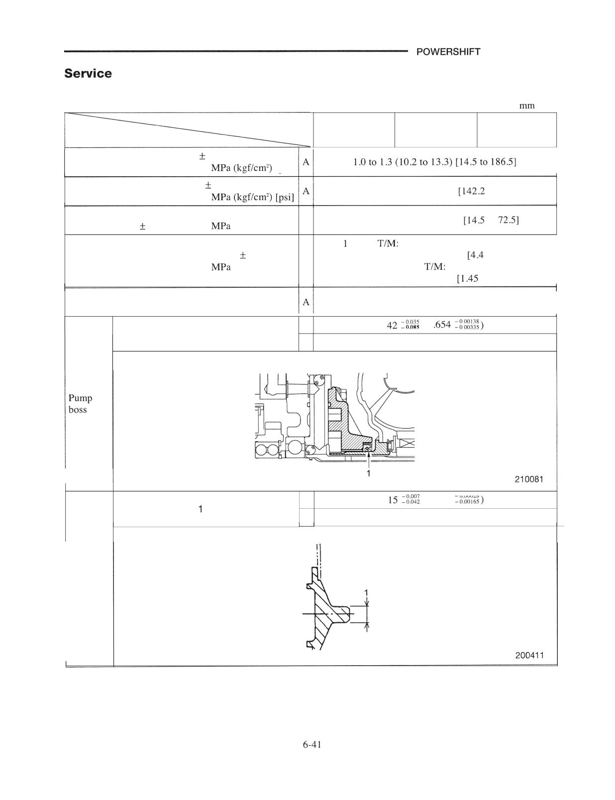
Data
A: Standard value B: Repair or service limit
Unit:
(in.)
Truck Models
1 ton class
2 ton class
3 ton class
Items
Main pressure (engine at 1600
100 rprn)
[psi]
Clutch pressure (engine at 1600
100 rprn)
0.98 to 1.28 (9.99 to 13.1)
to 185.71
Torque converter inlet pressure
A
0.10 to 0.50 (1.02 to 5.10)
to
(engine at 1600
100 rpm)
(kgf/cm2) [psi]
-speed
Lubricating oil pressure (engine at 1600
100 rpm)
0.03 to 0.29 (0.31 to 2.95)
to 42.11
A
(kgf/cm2) [psi]
Automatic 2-speed
0.01 to 0.15 (0.1 to 1.5)
to 21.81
Travel time for 100 m (330 ft) starting acceleration
5 seconds, maximum
(no load)
A
(1
Diameter of fitting surface in contact with
oil seal 1
B
41.85
(16.4763)
0.00028
A
(0.590
Diameter of shank
B
14.93 (0.5878)
TRANSMISSION
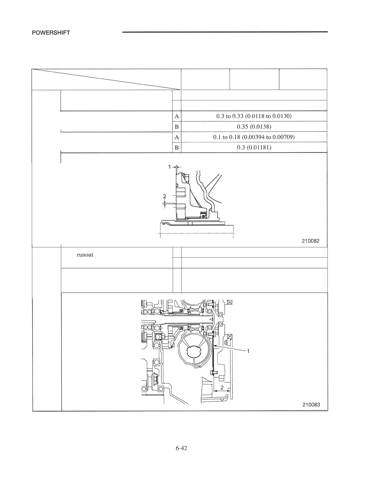
A: Standard value B: Repair or service limit
Unit: mm (in.)
Truck Models
1 ton class
2 ton class
3 ton class
Items
A
0.040 to 0.083 (0OO 157 to 0.00327)
Side clearance 1
B
0.15
(0.0059)
Top clearance 2
Backlash
Oil pump
A
0.2
(0.0079)
Face
of flexible plate 1
(in free state)
B
0.5
(0.0197)
Distance between end face of
transmission case and mating face of
A
50 (1.97)
flexible plate 2
Flexible
plate
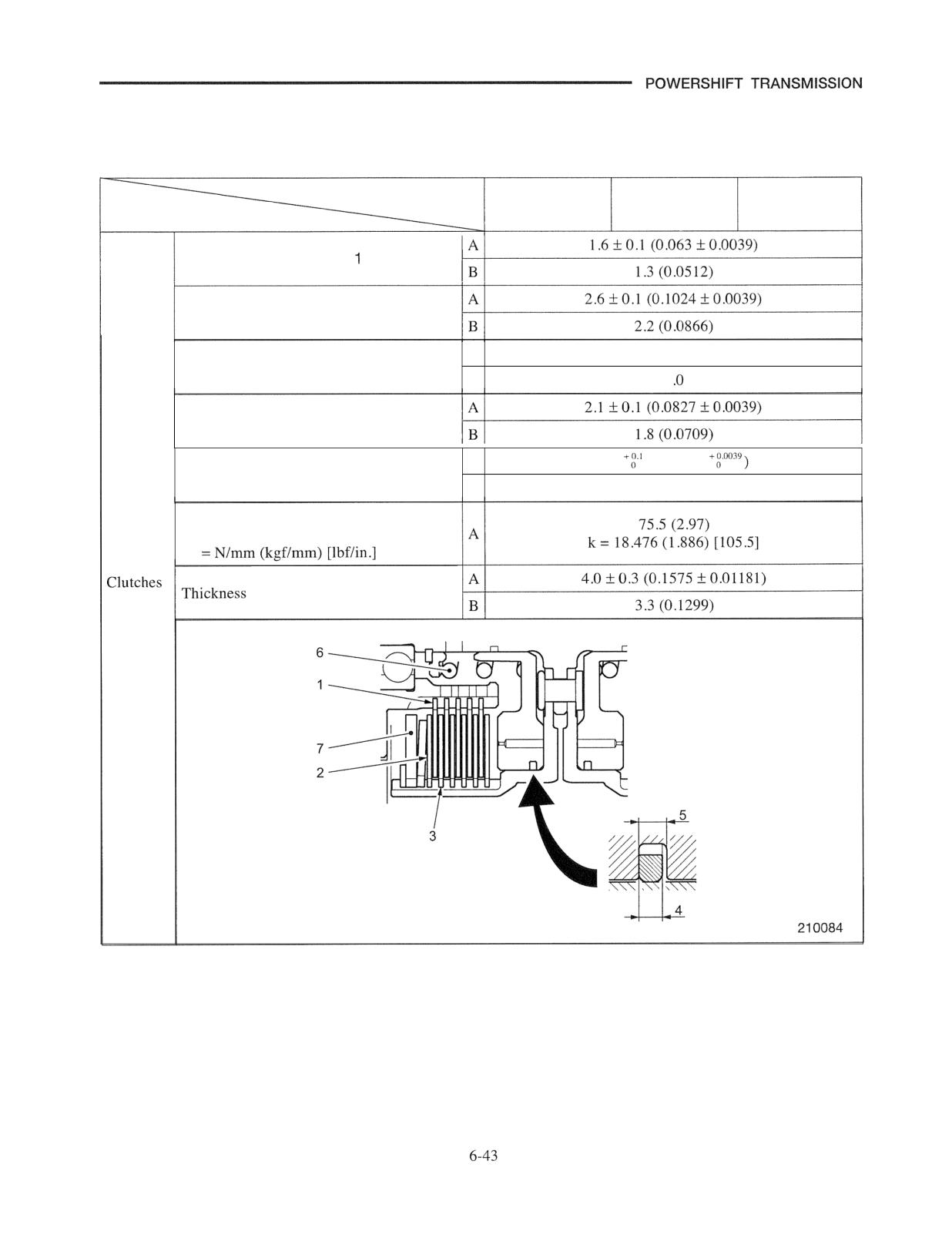
A: Standard value B: Repair or service limit
Unit: rnm (in.)
Truck Models
1 ton class
2 ton class
3 ton class
Items
I
Thickness of mating plate
Thickness of friction plate 2
A
0.13 to 0.29 (0.00512 to 0.01142)
Backlash of friction plate and gear 3
B
0.5 (0
197)
Width of seal ring 4
A
2.5
(0.0984
Width of piston seal ring groove 5
B
2.65
(0.10433)
Free length of clutch spring 6
Spring constant:
k
of pressure plate 7
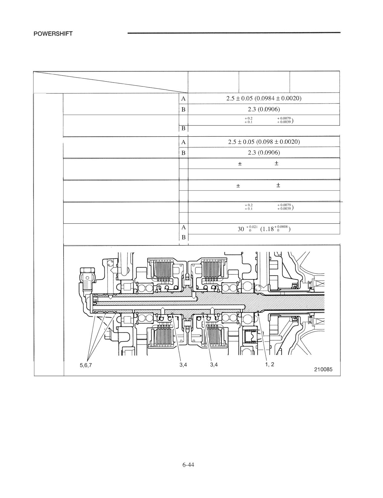
TRANSMISSION
A: Standard value B: Repair or service limit
Unit: mm (in.)
Truck Models
1 ton class
2 ton class
3 ton class
Items
Starter shaft seal ring width 1
A
2.5
(0.0984
Starter shaft piston seal ring groove
width 2
2.9
(0.1142)
I
Clutch piston seal ring width 3
A
2.8
0.05
(0.110
0.0020)
Clutch piston seal ring groove width 4
B
3.0
(0.1181)
A
2.5
0.05
(0.0984
0.0020)
Servo case shaft seal ring width 5
B
2.3
(0.0906)
A
2.5
(0.0984
Servo case shaft seal ring groove width 6
B
2.9
(0.1142)
Input
Servo case inside diameter contacting
shaft
seal ring 7
30.2
(1.189)
assembly
I
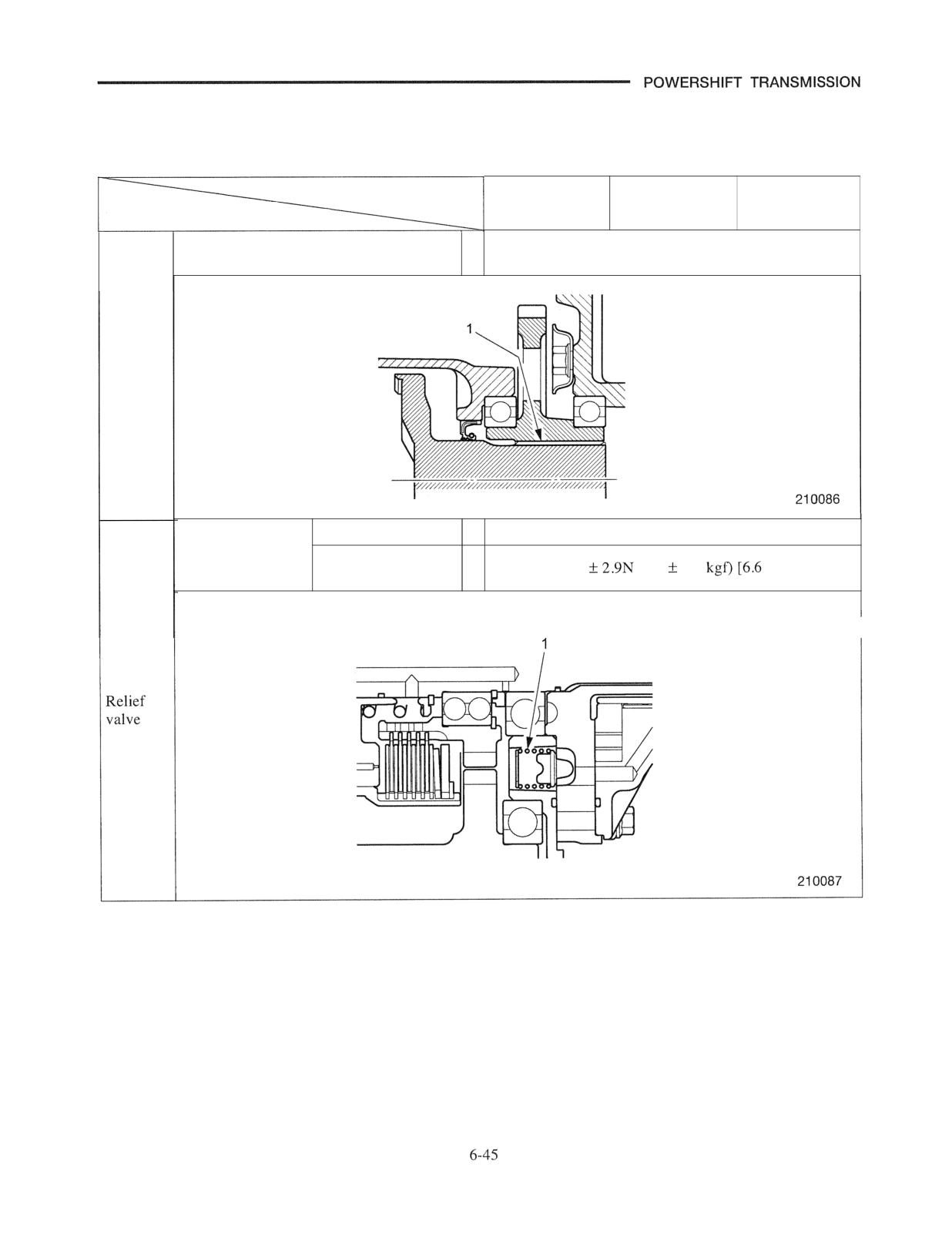
A: Standard value B: Repair or service limit
Unit: mm .in.,)
Truck Models
1 ton class
2 ton class
3 ton class
Items
Free movement of output fringe gear
A
0.054 to 0.14 (0.00213 to 0.0055)
(looseness of mating splines) 1
Output
shaft
Free length
A
35.15
(1.38)
Torque converter
Load at height
relief valve 1
B
29.4
(3.0
0.3
lbf]
15.5 mm (0.61 in.)
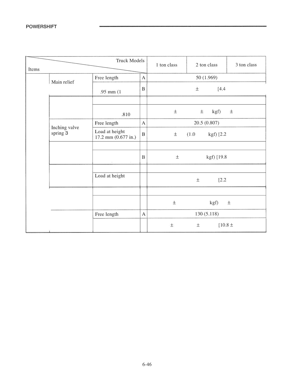
TRANSMISSION
A: Standard value B: Repair or service limit
Unit: mm (in.)
Load at height
outer spring 1
19.6 4 2 N (2
0.2 kgf)
4 0.5 Ibf]
28
140 in.)
Free length
A
78 (3.071)
Main relief
inner spring 2
Load at height
B
71.3
7.1 N (7.3
0.1
[16
1.6 lbf]
45.95 mm (1
in.)
9.7
1 N
4 0.1
4 0.2 lbf]
Free length
A
168 (6.614)
Control
Inching return
valve
spring 4
Load at height
88.3
7 N (9 4 0.7
4 1.6 lbf]
70 mm (2.756 in.)
Free length
A
70.89
(2.791)
Inching valve
return spring 5
B
9.7 4 1 N (1.0
0.1 kgf)
4 0.2 lbf]
18.2 mm (0.717 in.)
Free length
A
91 (3.583)
Accumulator valve
outer spring 6
Load at height
B
98
7.8 N (10 4 0.8
[22
1.8 lbf]
77.6 mm (3.055 in.)
Accumulator valve
inner spring 7
Load at height
B
48
3.9 N (4.9
0.4 kgf)
0.9 lbf]
50 mm (1.969 in.)
TRANSMISSION
FRONT AXLE AND
Structure
1
1 Ton Class
7-
1
2 Ton Class
7
2
3 Ton Class
7.
3
Removal and
Front Wheels
7
4
Front Axle and Reduction Differential
7
6
Disassembly and Reassembly
7
8
Front Axle
7.
8
Disassembly
7
8
Reduction Differential
7.
13
Disassembly
7.
13
Inspection and Repair
7.
16
Reassembly
7
17
Adjustment
7
23
Troubleshooting
. 25
Data
. 26
FRONT AXLE AND REDUCTION
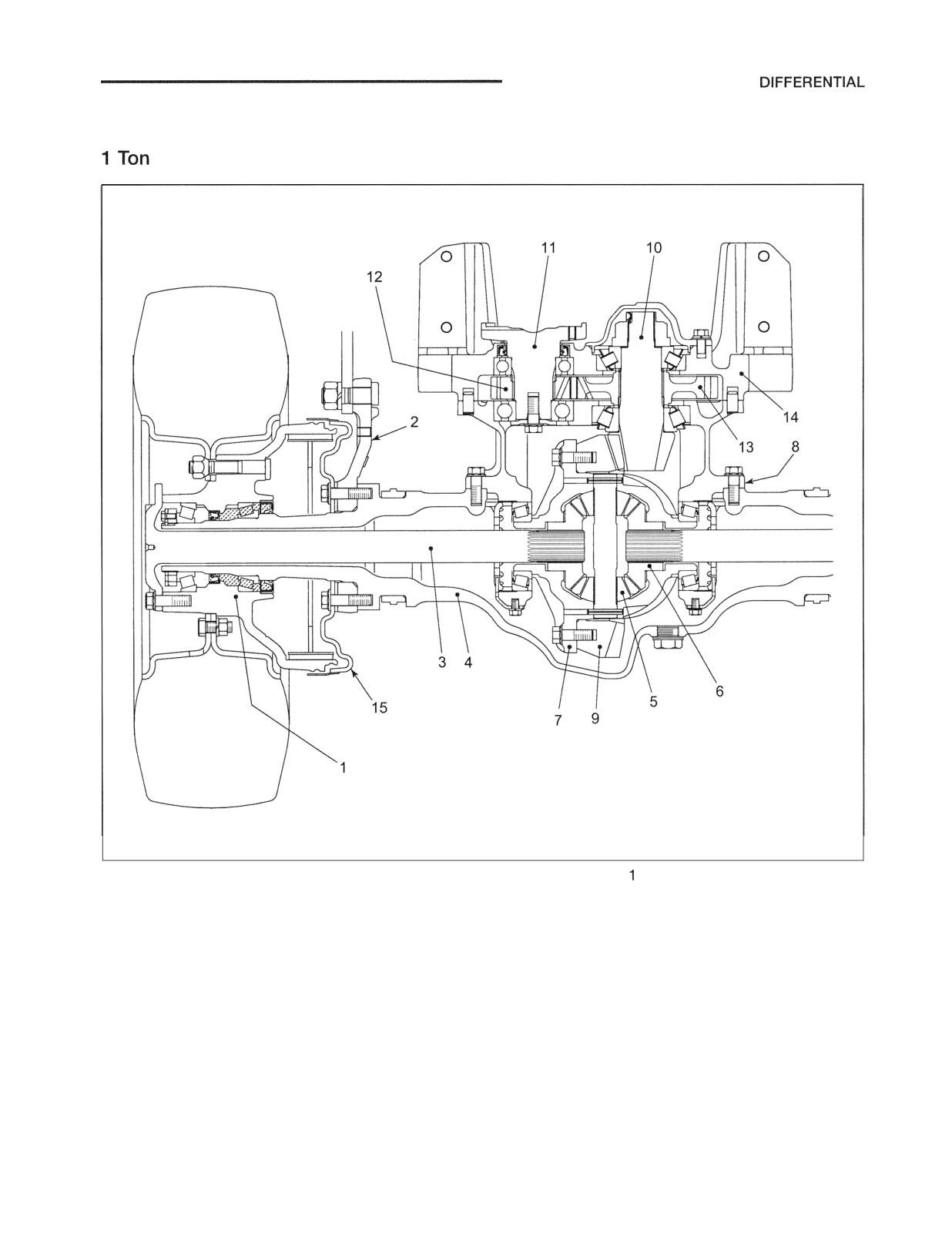
Structure
Class
210089
1 Front wheel hub
6 Differential gear
I
Input flange
2 Frame support
7 Differential case
12 Drive gear
3 Axle shaft
8 Differential carrier
13 Driven gear
4 Axle housing
9 Reduction gear
14 Carrier cover
5 Differential pinion
10 Reduction pinion
15 Backing plate
Frame support 2 is bolted to the front axle housing
The reduction differential is mounted to front axle
together with the backing plate 15 of wheel brake.
housing 4. The input Range 11 carries a drive gear
While front wheel hub 1 carries a single wheel, a
which meshes with the driven gear mounted on the
double wheel can be mounted to it with optional rim.
reduction pinion 1 0.
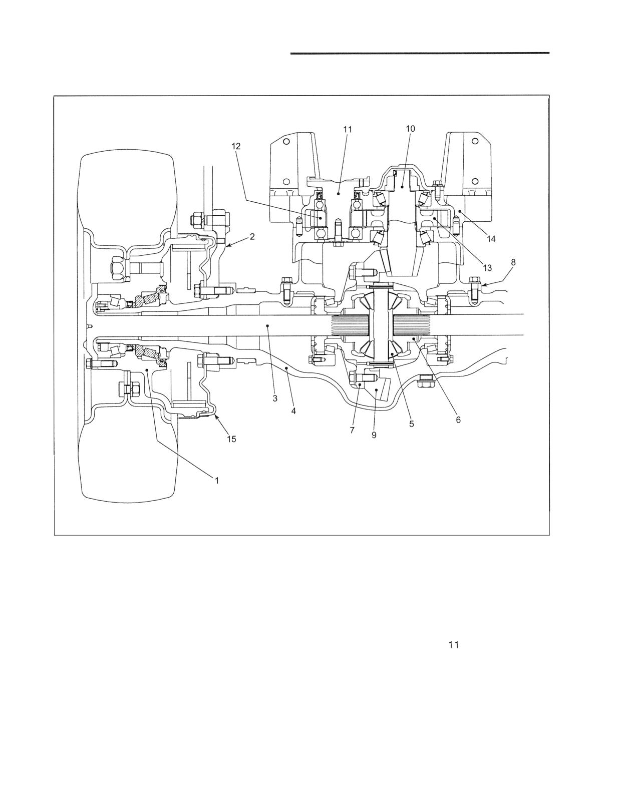
FRONT AXLE AND REDUCTION DIFFERENTIAL
2 Ton Class
210090
1 Front wheel hub
6 Differential gear
11 Input flange
2 Frame support
7 Differential case
12 Drive gear
3 Axle shaft
8 Differential carrier
13 Driven gear
4 Axle housing
9 Reduction gear
14 Carrier cover
5 Differential pinion
10 Reduction pinion
15 Backing plate
Frame support 2 is bolted to the front axle housing
The reduction differential is mounted to the front axle
together with the backing plate 15 of wheel brake.
housing 4. The input flange
carries a drive gear
While front wheel hub 1 carries a single wheel, a
which meshes with the driven gear mounted on the
double wheel can be mounted to it with optional rim.
reduction pinion 1 0.
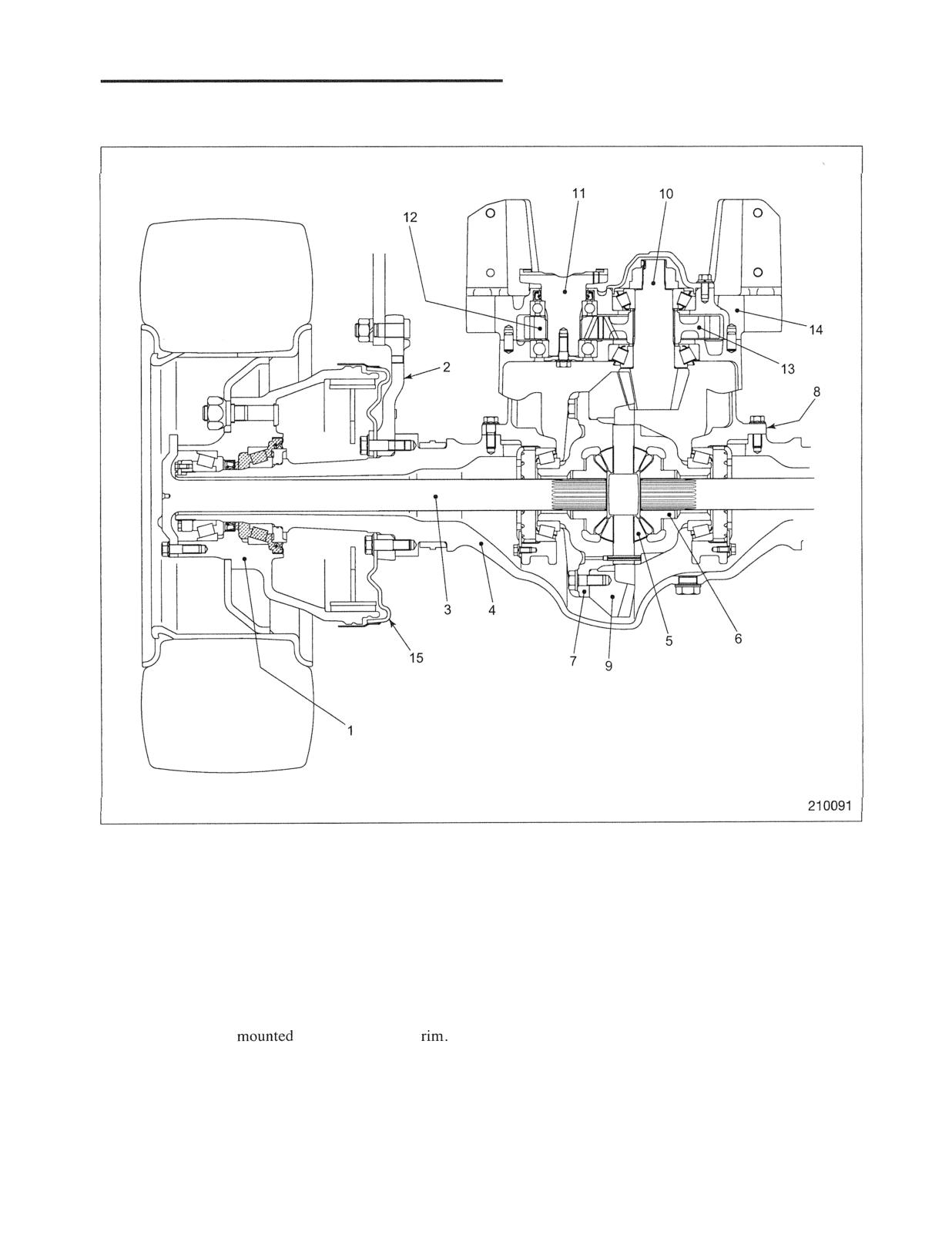
FRONT AXLE AND REDUCTION DIFFERENTIAL
3 Ton Class
1 Front wheel hub
6 Differential gear
11 Input flange
2 Frame support
7 Differential case
12 Drive gear
3 Axle shaft
8 Differential carrier
13 Driven gear
4 Axle housing
9 Reduction gear
14 Carrier cover
5 Differential pinion
10 Reduction pinion
15 Backing plate
Frame support 2 is bolted to the front axle housing
The reduction differential is mounted to the front axle
together with the backing plate 15 of wheel brake.
housing 4. The input flange 11 carries a drive gear
While front wheel hub 1 carries a single wheel, a
which meshes with the driven gear mounted on the
double wheel can be
on it with optional
reduction pinion 1 0 .
FRONT AXLE AND REDUCTION DIFFERENTIAL
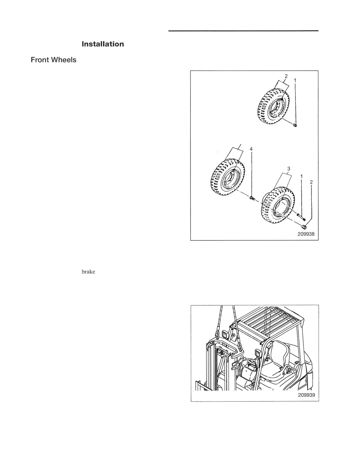
Removal and
Removal
[Single wheel]
[Single wheel]
1 Wheel nuts
2 Front wheel
[Double wheels]
1 Extension valve
[Double wheels]
2 Outer wheel nuts
5
3 Front wheel (outer)
4 Inner wheel nuts
5 Front wheel (inner)
Start by:
(a) Pull the parking
lever and block the rear wheels.
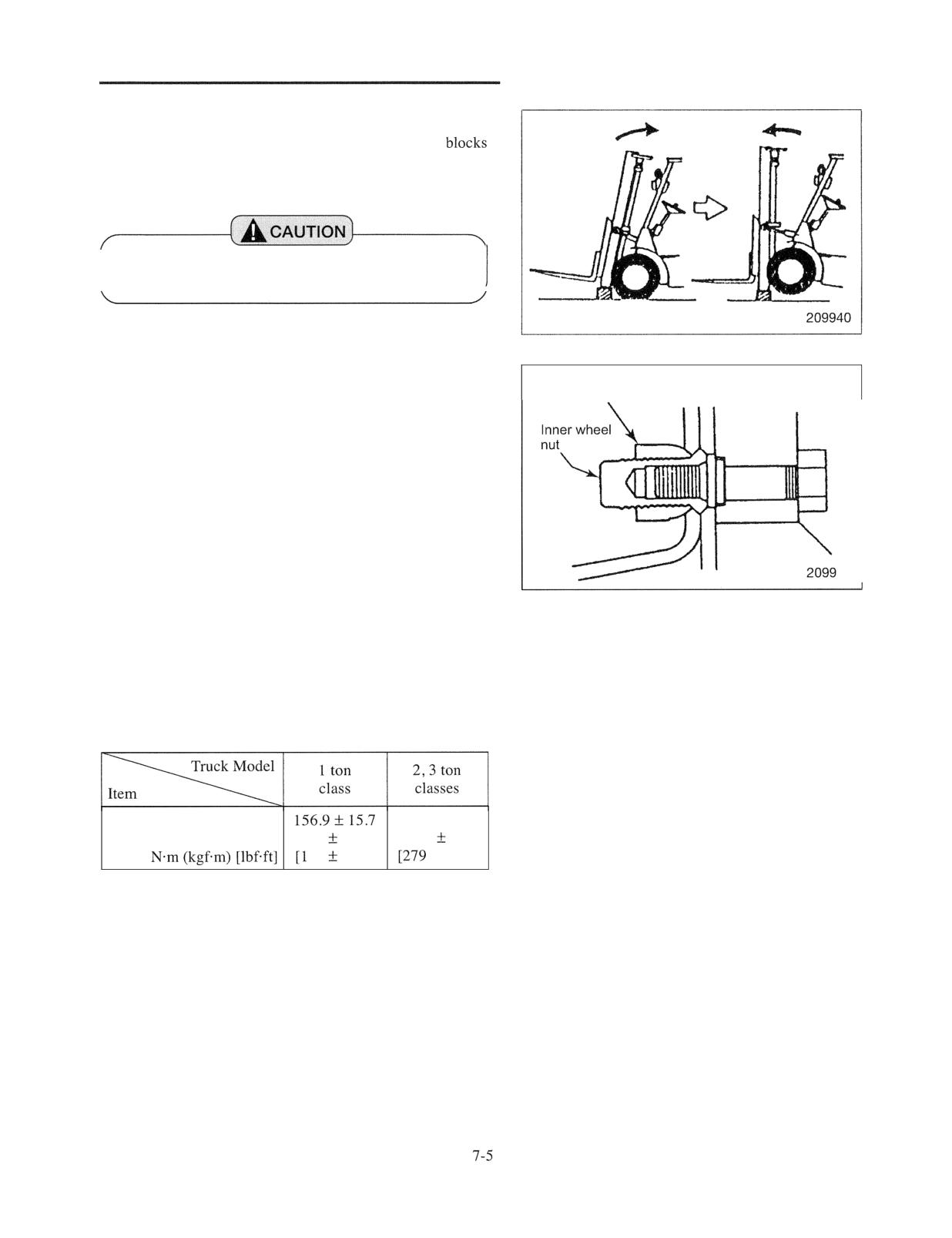
(b) Loosen the wheel nuts 1 by two turns. Then, raise the
front end of the truck using a hoist or the hydraulic
system.
(1) Hoisting
Using slings and eye-bolts at both ends of the cross
member on the outer mast, lift the front end of the
truck with a hoist.
FRONT AXLE AND REDUCTION DIFFERENTIAL
(2) Using hydraulic system
Tilt the mast all the way back and place wood
under the mast in the appropriate places. Then, tilt the
mast forward to raise the front end.
After raising the front end, place jack stands
under the frame to prevent the truck from falling.
I
Suggestion for Removal
Outer wheel
nut
In the case of double wheels, remove the outer wheel nuts
and outer wheel. Then, remove the inner wheel nuts and
inner wheel.
Installation
To install, follow the removal sequence in reverse, paying
attention to the following points.
(1) Tighten the wheel nuts evenly to the specified torque
so that the wheels will not wobble during operation.
Tightening torque for
377.6537.8
wheel nuts
(16
1.6)
(38.5
3.9)
16
11.61
5 27.91
FRONT AXLE AND REDUCTION DIFFERENTIAL
Front Axle and Reduction Differential
Removal
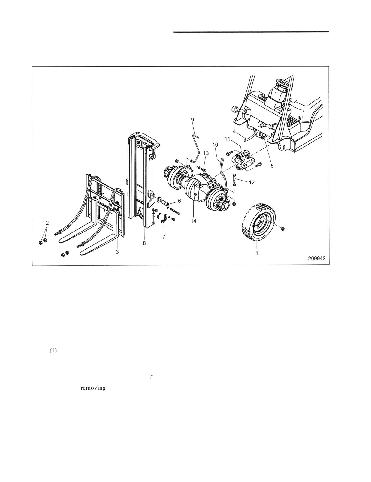
Sequence
8 Mast
1 Front wheel
9 Brake pipe
2 Nuts
10 Parking brake cable
3 Fork, Lift bracket
11 Universal joint
4 Return hose for lift cylinder
12 Bolt, Nut
5 High-pressure hose for lift cylinder
13 Bolt, Nut
6 Tilt cylinder socket
14 Front axle and reduction differential
7 Mast support bearing cap
Note:
For removal of the front wheel I , refer to "'Front
Wheels. Removal."
(2) For removal of mast parts 2 through 8, refer to
"GROUP 12 MAST AND FORKS
(3) Before
the front axle and reduction
differential, remove the front axle drain plug
and drain transfer and differential oil.
FRONT AXLE AND REDUCTION DIFFERENTIAL
Suggestions for Removal
Removing bolt 1 2
Bolts 12 are coupling the transmission with the differential.
Before removing these bolts, place a wood block under the
transmission to support it.
(2) Removing parking brake cable
To remove the parking brake cable, remove the parking
brake lever assembly from the dashboard and disconnect
the cable from the lever.
Note: To dismount the reduction differential alone, remove
the front axle as described above. To dismount the
reduction differential after removal of the engine and
transmission, the front axle does not need to be
removed from the truck.
Installation
To install, follow the removal sequence in reverse, paying
attention to the following points.
(1) After connecting the parking brake cable, make sure
that the brake lever operating effort is within the
specification.
245 to 294 N
Parking brake lever operating
(25 to 30 kgf)
effort
[55 to 66 lbf]
(2) Before installing the mast, bleed the brake fluid circuits
of trapped air. For bleeding, refer to '"CROUP 9
BRAKE SYSTEM."
(3) After installing the mast, make sure that tilt angles,
forward and backward, are correct and that the lift
chains, right and left, are equal in tension. Refer to
"'GROUP 12 MAST AND FORKS
(4) Fill the front axle housing with oil up to the plug hole
level.
FRONT AXLE AND REDUCTION DIFFERENTIAL
Disassembly and Reassembly
Front Axle
Disassembly
Sequence
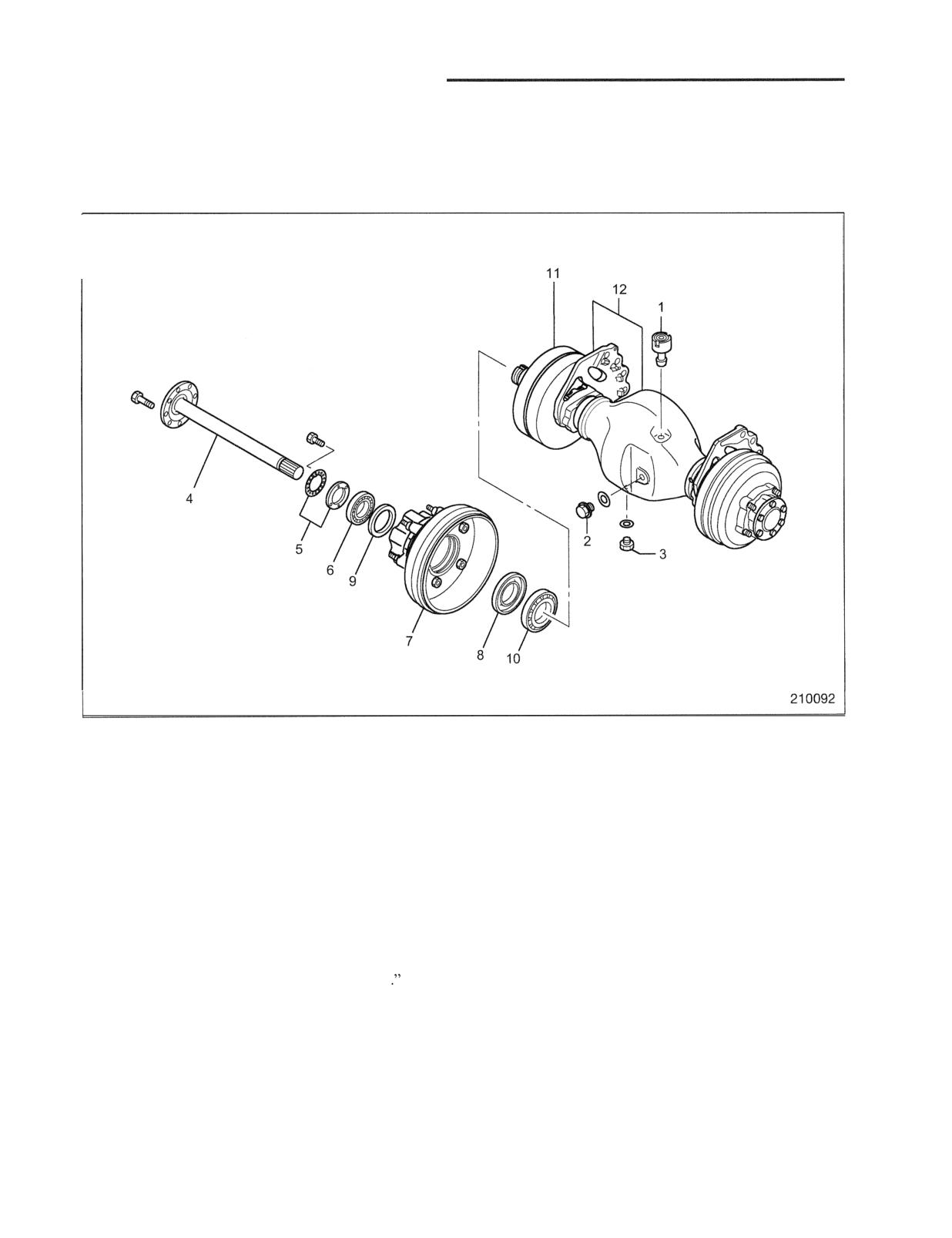
1 Air bleeder
7 Front wheel hub, Brake drum
2 Level plug
8 Oil seal
3 Drain plug
9 Oil seal
4 Axle shaft
10 Tapered roller bearing
5 Lock ring, Lock nut
11 Brakeassembly
6 Tapered roller bearing
12 Frame support, Axle housing
Start by:
(a) Remove the mast. For replacement of the front
Note: It is not necessary to remove the axle housing or
axle housing and disassembly of the differential,
to drain the oil when removing the axle shaft or
refer to "GROUP 12 MAST AND FORKS
disassembling the wheel hub.
(b) Jack up the truck.
(c) Support the front end of the truck with blocks or
stands at both sides to keep the truck in the
horizontal position.
(d) Remove the front wheels.
FRONT AXLE AND REDUCTION DIFFERENTIAL
Suggestions for Disassembly
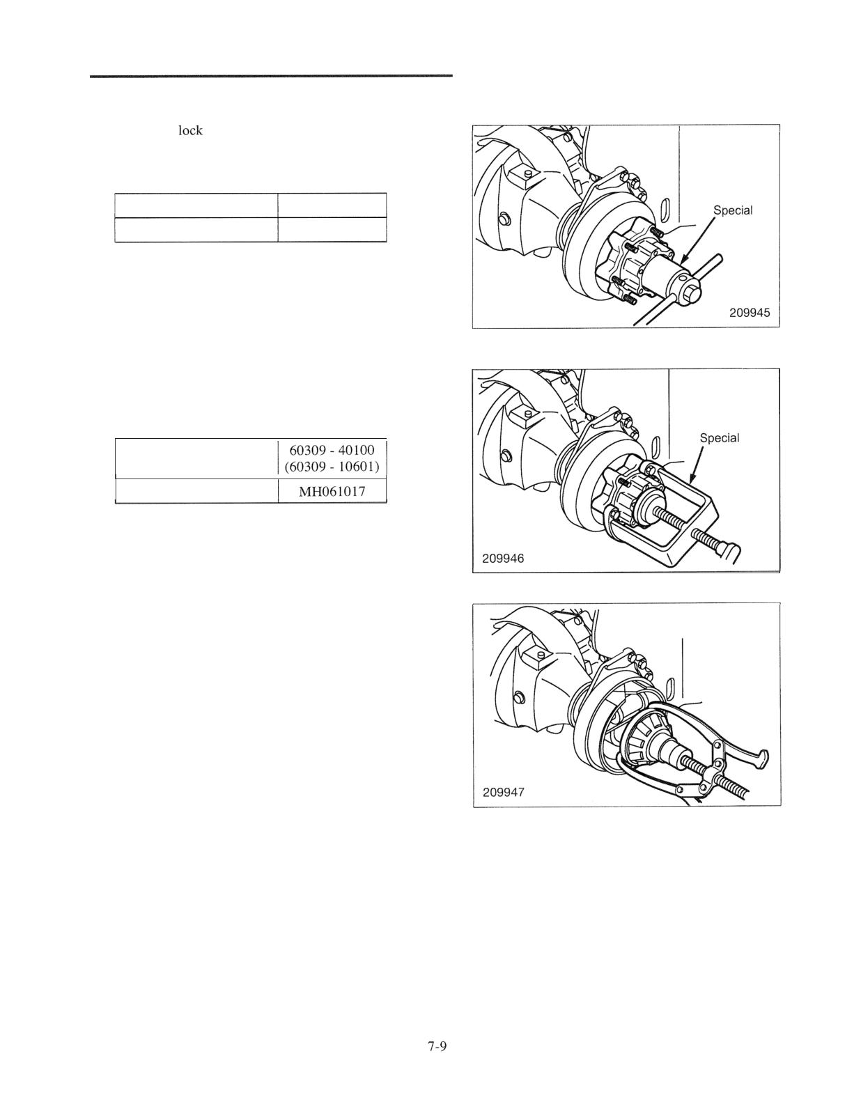
(1) Removing
nut
Use the lock nut wrench (special tool).
Special tool needed
1 ton class
91268-00800
tool
2,3 ton classes
03703 - 59001
(2) Removing front wheel hub
Use the wheel hub puller (special tool).
Special tool needed
I
tool
1 ton class
I
2,3 ton classes
Note: It is not necessary to remove the oil seal from the
hub nor disassemble the oil deflector unless the seal
is defective.
(3) Removing bearings
The inner race of the tapered roller bearing remains in the
axle housing when the hub is drawn out. Remove this race
together with the seal retainer with a bearing puller.
Note: Trucks of 1 ton class do not have the seal retainer.
FRONT AXLE AND REDUCTION DIFFERENTIAL
Inspection after Disassembly
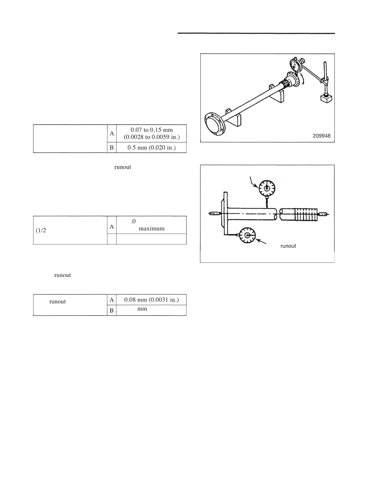
(1) Axle shaft
(a) Looseness of mating splines
Mount the differential level gear on the splined end of
the shaft and set a dial indicator as shown. Rotate the
bevel gear in the direction shown and read the free play
(looseness of mating splines).
A: Standard value B: Repair or service limit
Free movement
(looseness of mating
splines)
(2) Shaft deflection and flange
Deflection of shaft
(a) Set a dial indicator at the middle part of the axle
shaft. Rotate the shaft and read the dial indicator
(deflection of axial shaft).
A: Standard value B: Repair or service Iimit
1 mm (0.039 in.)
Deflection of axle shaft
of dial indicator
reading)
B
2.0 mm (0.079 in.)
Face
of flange
209949
(b) Set a dial indicator against the flange of the axle
shaft as shown. Rotate the shaft and read the face
of flange.
A: Standard value B: Repair or service limit
Face
of axle shaft
flange
0.5
(0.020 in.)
(3) Axle housing
(a) Check the surfaces of axle housing in contact with
the mast bearing for damage.
(b) Check the entire axle housing for distortion, dents
and other defects. Pay particular attention to the
welds to see if any weld is cracked to require
repair.
(4) Others
(a) Check the outer surface of oil seal and retainer for
wear or damage.
(b) Check the outer and inner oil seals for wear or
damage.
FRONT AXLE AND REDUCTION DIFFERENTIAL
Reassembly
To reassemble, follow the disassembly sequence in reverse,
paying attention to the following points.
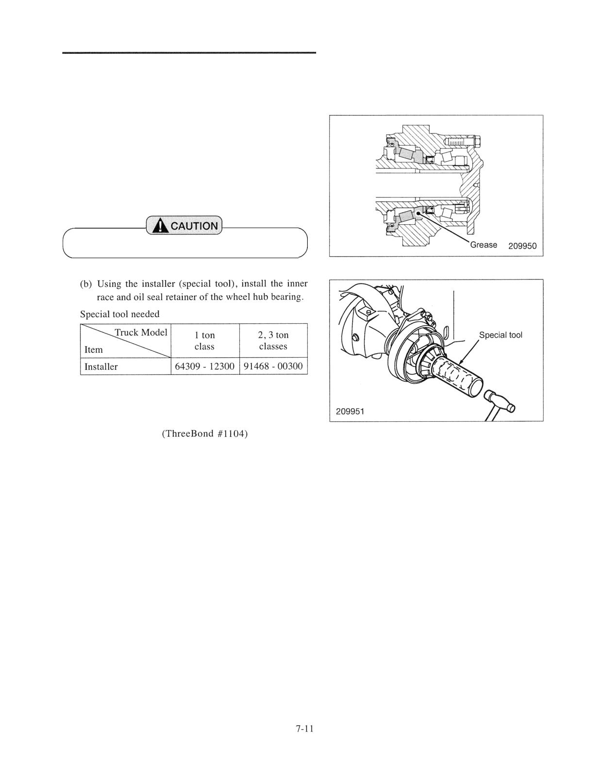
(1) Front wheel hub
(a) Fill grease (Autolex A or equivalent) in the front
wheel hub as shown.
Stuff grease in the roller holder of the tapered
roller bearing (inner) using the palm.
Apply grease to the lip groove of oil seal.
Use care not to let grease in the brake drum.
(c) Apply sealant
to the flange
surfaces of the axle shaft.
FRONT AXLE AND REDUCTION DIFFERENTIAL
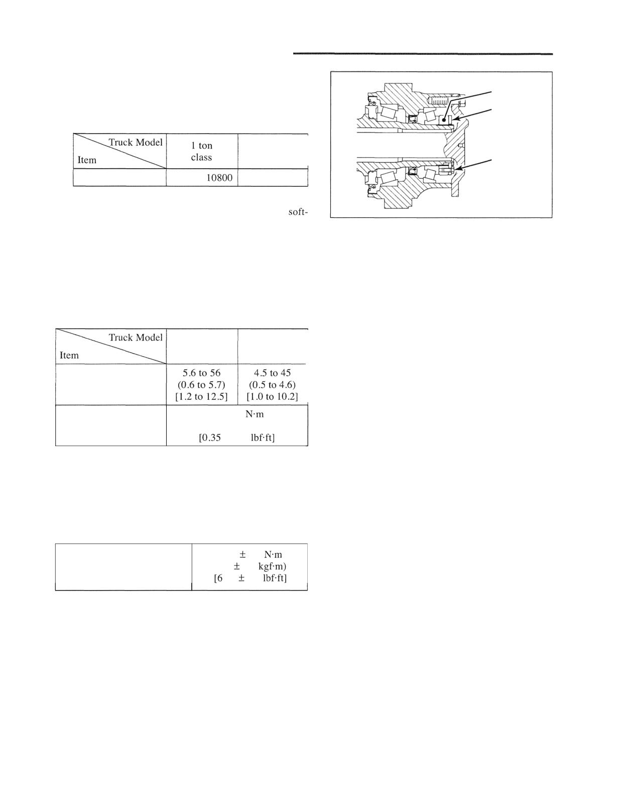
(2) Hub bearing preload adjustment and lock nut
(a) Install the nut hand-tight with a socket wrench
Nut
(special tool).
Lock ring
Special tool needed
2,3 ton
classes
Lock bolt
Socket wrench
91268 -
03703 - 59001
210093
(b) Rotate the hub and tap its periphery with a
head mallet for snug assembling.
(c) Fully tighten the lock nut to obtain hub bearing
preload within the specified limits.
Note: To check the hub bearing preload, hook a spring
scale on the hub bolt, then pull it to measure the
tangential force of the hub bolt.
Unit: N (kgf) [lbf]
1 ton
2,3 ton
class
classes
Tangential force of hub
bolt (increment from
when preload is zero)
Starting torque of hub
0.5 to 5
rotation (increment from
(0.1 to 0.5 kgf-m)
when preload is zero)
to 3.7
(d) Fit the lock ring into place and tighten the lock
bolt.
(e) Check the preload again.
(3) Drain plug
(a) Tighten the drain plug to the specified torque.
83.4
7.8
Tightening torque
(8.5
0.8
1.5
5.8
FRONT AXLE AND REDUCTION DIFFERENTIAL
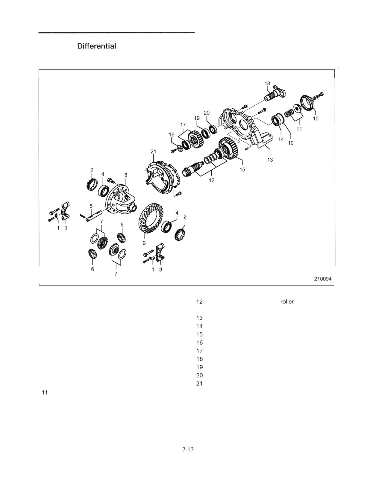
Reduction
Disassembly
Sequence
1 Lock plate
Reduction pinion, Tapered
bearing
2 Adjusting screw
(inner), Shims
3 Bearing cap
Carrier cover
Remove parts 4 through 9 as an assembly
Tapered roller bearing
4 Tapered roller bearing
Driven gear
5 Pinion shaft
Plate
6 Differential pinion
Drive gear, Ball bearing
7 Bevel gear, Spacer
Input flange
8 Differential case
Ball bearing
9 Bevel gear
Oil seal
10 Cover, O-ring
Differential case
Lock nut, Shims
FRONT AXLE AND REDUCTION DIFFERENTIAL
Suggestions for Disassembly
Note: (1) Before disassembling the differential, except for
replacement of the reduction gear set, be sure to
measure the gear backlash to ensure correct
backlash at the time of reassembly.
Truck Model
3 ton
classes
class
Backlash between
0.20 to 0.28 mm
0.25 to 0.33
reduction gear and
(0.00'79 to
(0.0098 to
reduction pinion
0.0110 in.)
0.0130 in.)
(2) Provide a matching mark across the bearing cap,
adjusting screw and carrier on each side to
ensure correct refitting.
Removing bearing
Use a bearing puller to remove the inner bearing.
(2) Removing shims
After removing the lock nut
and shims, check and
record the total thickness of the shims. Tie the shims to the
lock nut so as not to be lost.
FRONT AXLE AND REDUCTION DIFFERENTIAL
(3) Removing tapered roller bearing
Do not remove the tapered roller bearing
from the
reduction pinion 12 unless it is defective.
(4) Removing carrier cover
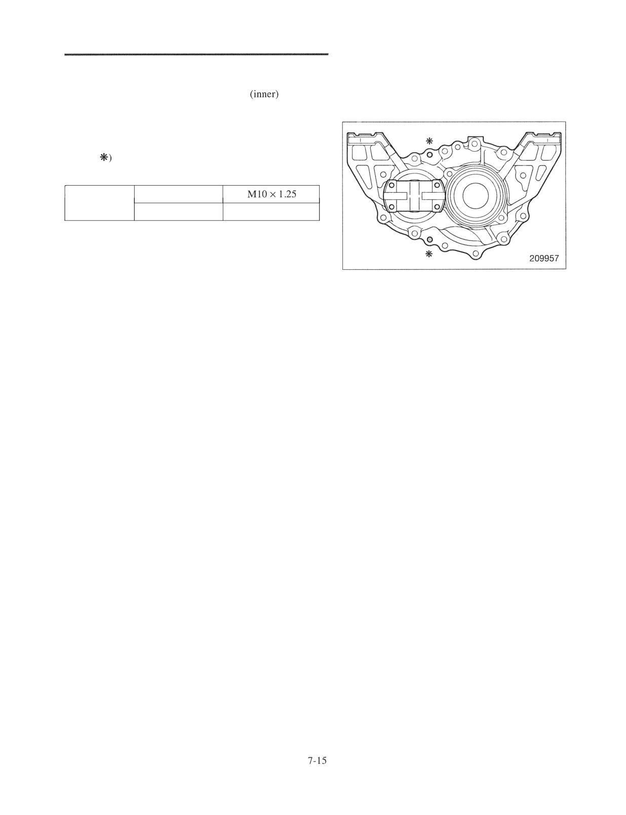
Screw jack bolts in two jack bolt holes (at the positions
marked
and remove the carrier cover 1 3 while tapping
near dowel pins (2 places) with a plastic mallet,
Size
Jack bolt
Nominal length
20 mm (0.79 in.)
(5) Checking oil seal
Do not remove the oil seal 20 from the carrier cover 13
unless it is defective.
FRONT AXLE AND REDUCTION DIFFERENTIAL
Inspection and Repair
Reduction bevel gear and pinion
(a) Check the gear and pinion for tooth contact, wear,
pitting, flaking and chipping.
(b) Minor flaws on the tooth surfaces can be repaired
by grinding with an oil stone or sandpaper.
(c) If the gear
pinion is badly damaged, replace
them as a set.
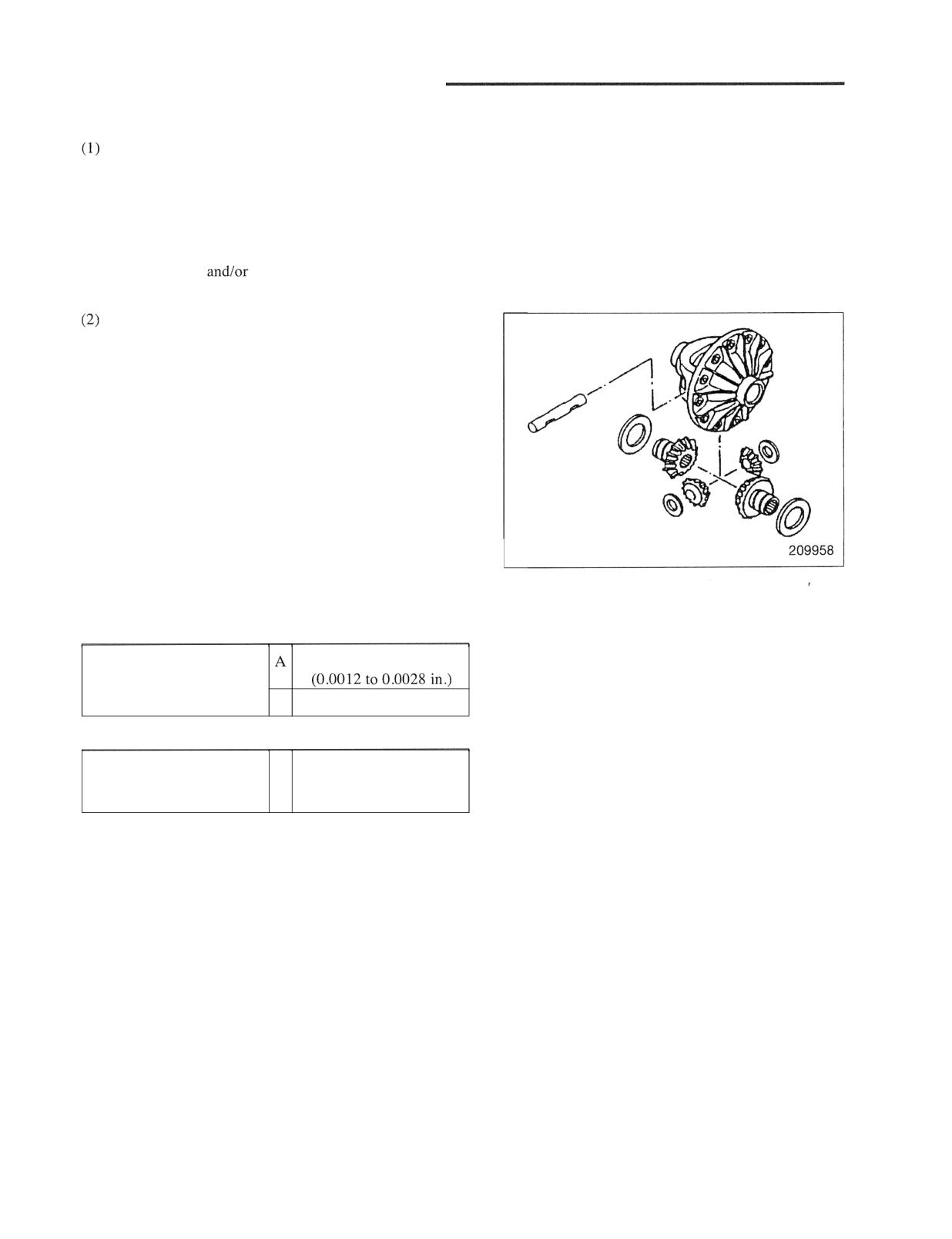
Differential
(a) Check the differential case and tapered roller
bearing inner race to see if the seat surface is
fretted.
(b) Check the differential case for cracks. Check the
sliding contact surfaces of thrust washer and gears
for wear and damage.
(c) Check the teeth of the differential pinions and
gears for wear, pitting, chipping and galling.
(d) Check the pinions (inner surface) and pinion shafts
(outer surface) for wear.
(e) Check the differential gears and axle shaft splines
for wear and free play (looseness).
A: Standard value B: Repair or service limit
0.03 to 0.07 mm
Clearance between pinions
and shafts
B
0.35 mm (0.0138 in.)
A: Standard value B: Repair or service limit
Free play (looseness) of
differential gear and axle
A
0.5 mm (0.020 in.)
shaft splines
(3) Drive gear and driven gear
(a) Check the gears for tooth contact, wear, pitting,
galling and chipping.
(b) Replace the gears as a set if they are defective.
Note: (1) The combination of drive and driven gears is
different between one model of the truck and
another.
(2) The combination can be identified by the
alphabetical marks A up to F stamped on the
side face of the gears.
(3) Before replacing the gears, always check the
marks to make sure of the correct combination.
FRONT AXLE AND REDUCTION
Reassembly
ton class
2 ton class
3 ton class
FRONT
AND REDUCTION
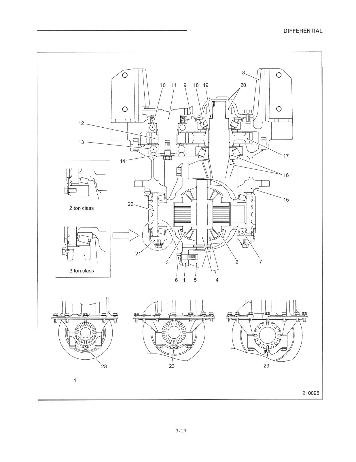
Sequence
Differential case
Bail bearing
Differential gear, Thrust washer
Plate
Differential gear, Thrust washers
Differential carrier
Differential pinion, Pinion thrust washer (2, 3
Bevel pinion, Shims, Tapered roller bearing
ton classes), Pinion shaft, Spring pin
(inner)
Bevel gear
Driven gear
Tapered roller bearing
Tapered roller bearing
Shims
Carrier cover
O-ring, Cover
Oil seal
Bearing cap
Ball bearing
Adjusting screw
Input flange
Lock plate
Drive gear
Suggestions for Reassembly
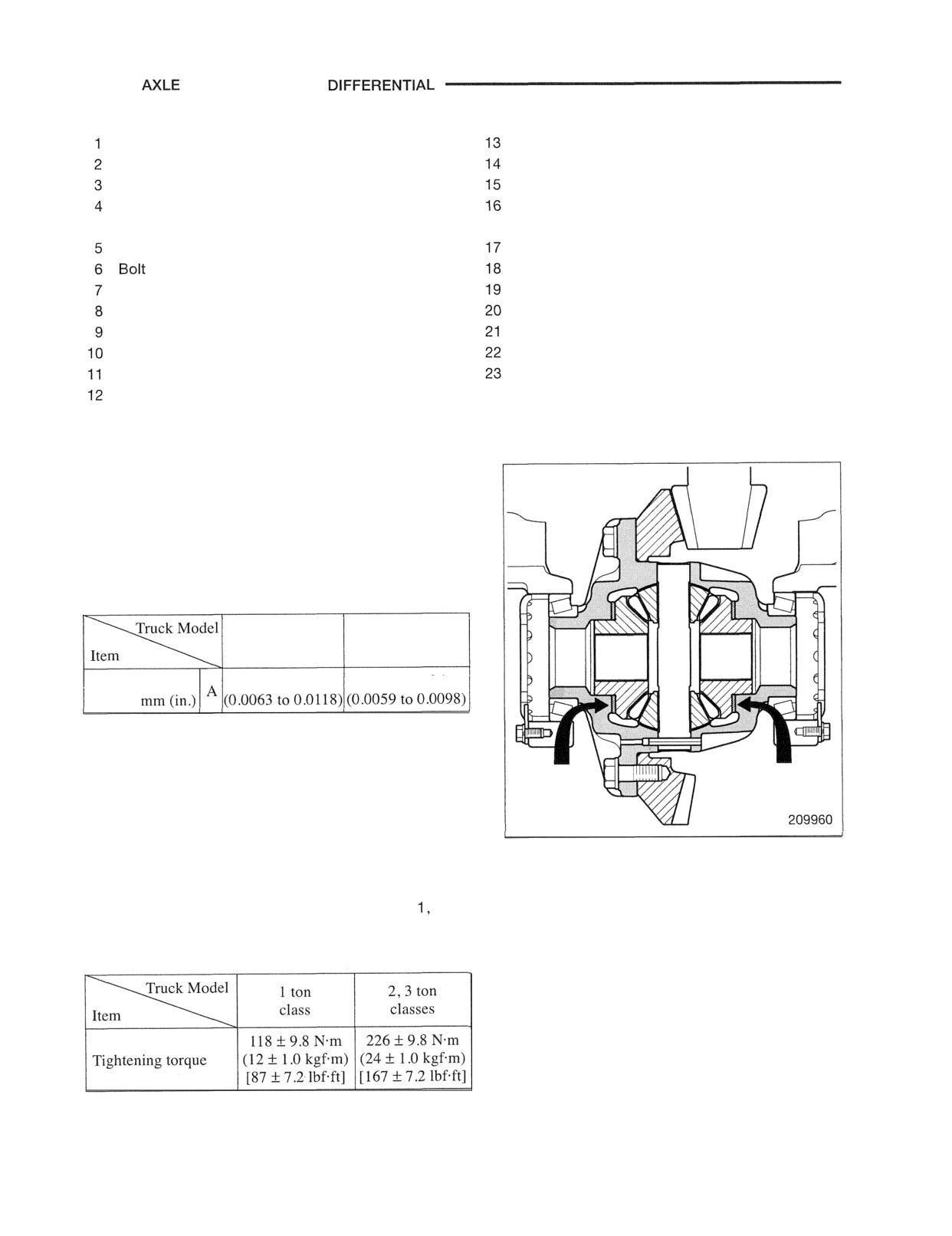
(1) Reassembling differential pinions
For adjusting the backlash between the differential gears
and pinions, use the thrust washers of the differential gears.
Measure the backlash and if it exceeds the standard value,
replace the thrust washers.
A: Standard value
2,3 ton
class
classes
Backlash
0.16 to 0.30
0.15 to 0.25
(2) Installing reduction gear
To install the bevel gear 2 to the differential case
apply
LOCTITE No. 271 to the threads of bolts 6 and tighten the
bolts to the specified torque.
FRONT AXLE AND REDUCTION DIFFERENTIAL
(3) Installing differential case assemblies
Place the case assembly on the carrier, and tighten cap bolts
snugly to fit the bearing caps tentatively.
(4) Installing bearing caps
The bearing cap and differential carrier are machined in
one process. Be sure to identify the left and right caps by
matching marks and install them in place.
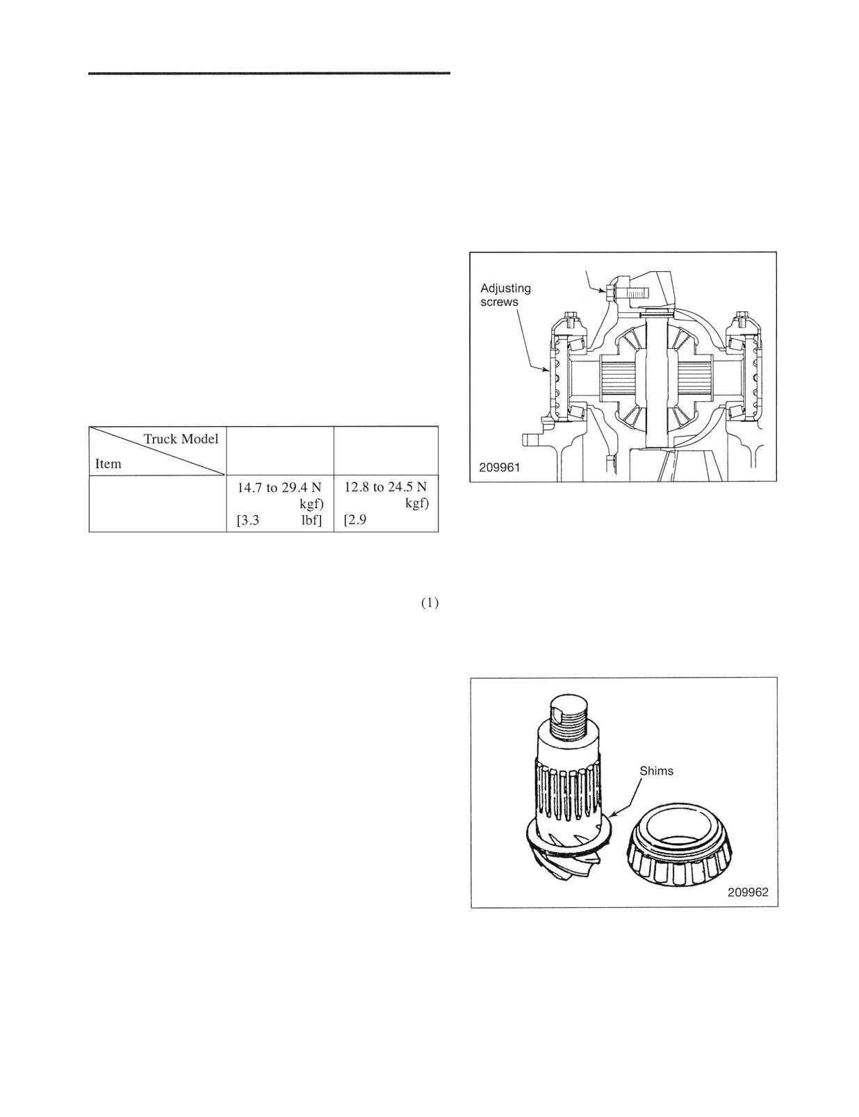
(5) Adjusting bearing preload
Bolt
(a) Rotate the reduction gear by hand, and tap its back
side with a soft-head mallet for snug assembling.
(b) Hook a spring scale on the bolt 6, and pull it in the
tangential direction to read the force when the gear
starts rotating (preload for the bearing).
(c) Adjust the preload by means of the right and left
adjusting screws.
1 ton
2,3 ton
class
classes
Preload
(1.5 to 3.0
(1.3 to 2.5
to 6.6
to 5.5 lbf]
(6) Removing differential cases
The preload can be determined by doing the steps
through (5) above. Provide match marks across the
adjusting screws and bearing caps, and remove the
differential cases from the carrier.
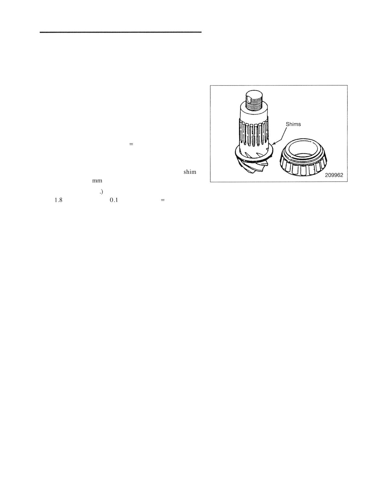
(7) Shimming reduction pinion
Refer to page 7-23.
FRONT AXLE AND REDUCTION DIFFERENTIAL
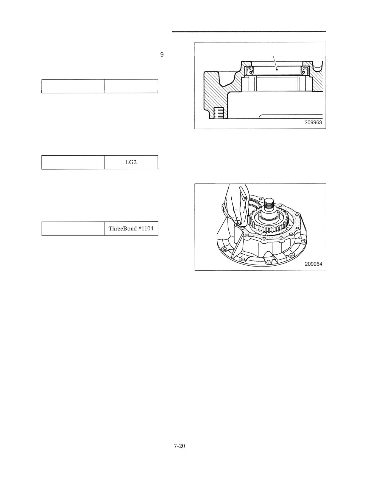
(8) Installing oil seal
Oil seal
Using the installer (special tool), fit the oil seal
in the
carrier cover 8.
Special tool needed
Installer
91263-15400
Note: Be sure that the lip of oil seal faces in the right
direction.
(9) Applying grease to oil seal
Apply grease to the oil seal installed to the carrier cover 8
Specified grease
(10) Applying sealant
When fitting the carrier cover 8 to the differential carrier
15, apply sealant to the flange.
Sealant
FRONT AXLE AND REDUCTION DIFFERENTIAL
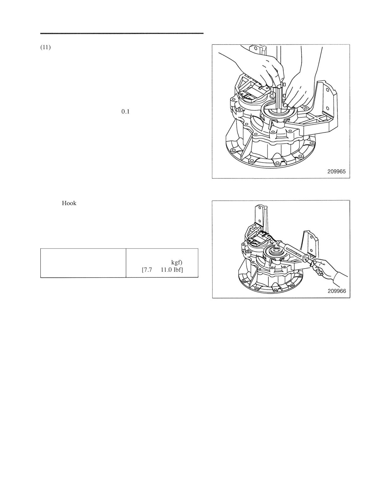
Adjusting reduction pinion preload
(a) After installing the tapered roller bearing 18,
measure gap between the reduction pinion and
tapered roller bearing to determine the required
total shim thickness. The standard value of total
shim thickness is 1.25 mm (0.049 in.).
(b) Five different thicknesses of shims are available -
0.05 mm (0.0020 in.),
mm (0.0039 in.), 0.2 mm
(0.00'79 in.), 0.5 mm (0.020 in.) and 1.0 mm
(0.0394 in .) . Use appropriate shims and tighten the
plate 1 4.
(c)
a spring scale onto the bolt hole of the input
flange, and pull it in the tangential direction to
check the preload for the tapered roller bearing (the
force when the flange starts rotating). Adjust the
preload by increasing or decreasing the shims.
34.32 to 49.03 N
Tangential force
(3.5 to 5.0
(spring scale reading)
to
(12) Adjusting reduction gear and reduction pinion tooth
contact
(a) After checking the reduction pinion preload, put
the differential carrier upside down.
(b) Install the differential cases (removed at Step 6) to
the carrier. Align the match marks on the bearing
caps and adjusting screws on each side.
FRONT AXLE AND
DIFFERENTIAL
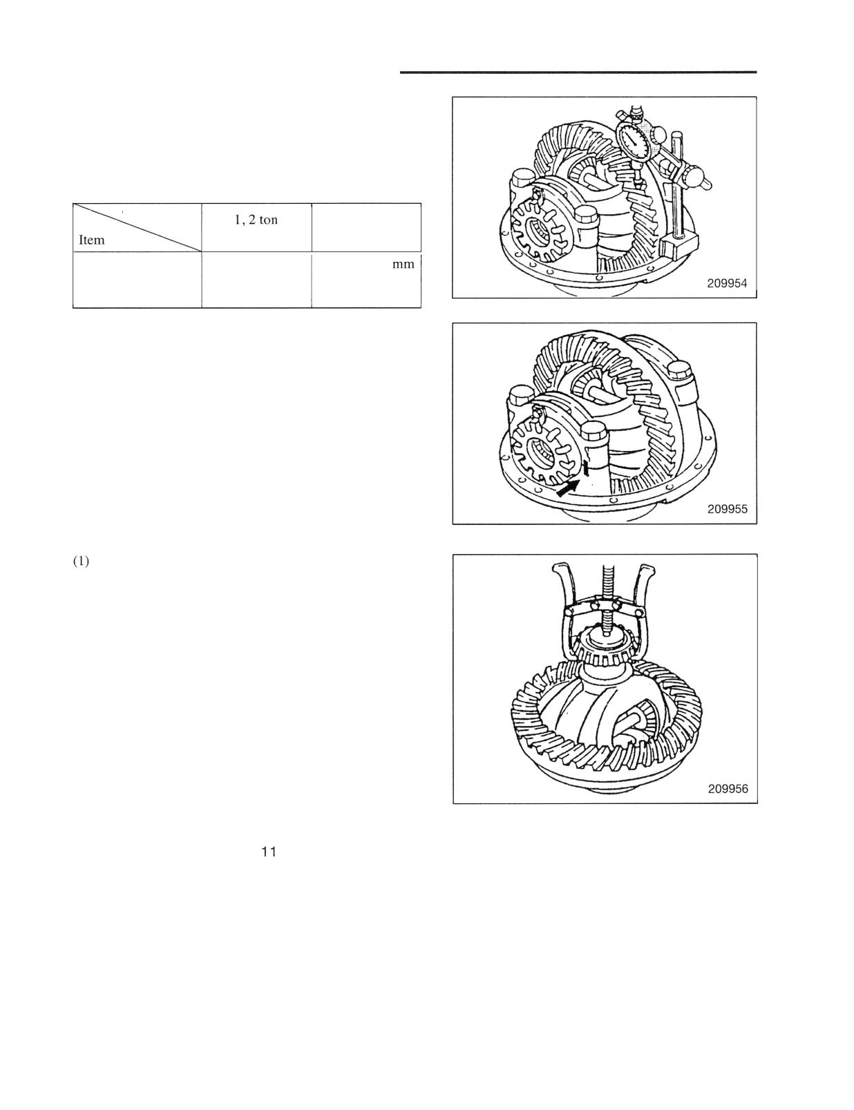
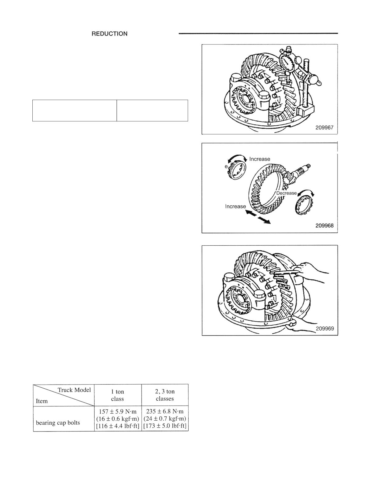
(c) Using the adjusting screws, adjust the backlash
between the reduction gear and pinion.
Set a dial gauge with its probe at a right angle to
the tooth face of the reduction gear as shown.
Turning the gear back and forth, read the tangential
play of the gear.
Backlash between reduction
0.15 to 0.25 mm
gear and pinion
(0.0059 to 0.0098 in.)
(d) When adjusting the backlash, turn the adjusting
Backlash
screws, right and left, equally in the same direction
so as not to affect the bearing preload.
Decreas
Increase
Backlash
Decrease
(e) Apply a thin and even coat of colorant to a few
reduction gear teeth, on both drive and coast sides.
Rotate the reduction gear back and forth by hand
until a contact pattern is located on both sides of
the gear teeth.
Note: Refer to "Tooth Contact Patterns and
Adjustment" on page 7-24.
(13) Tightening bearing caps
After checking the tooth contact, tighten the bearing
cap bolts to the specified torque, and bend the lock
plate to clinch the bearing cap.
Tightening torque for
FRONT AXLE AND REDUCTION DIFFERENTIAL
Adjustment
Adjusting reduction gear tooth contact
After the reduction gear and pinion have been replaced,
adjust the tooth contact as follows.
(1) Determine the required total shim thickness by
calculating on the basis of machining error marked on
the end face of the reduction pinion as follows. Put on
the determined total thickness of shims and install the
reduction gear and pinion.
Total shim thickness required
Standard value - (machining error)
(Example)
If the error is - 0.10 rnrn (- 0.004 in.), the total
thickness is 1.9
(0.075 in.)
1.8 mm (0.07 1 in
- (- 0.1 rnm (-0.004 in .) =
mm (0.071 in.) + rnm (0.004 in.)
1.9 rnrn (0.075 in.)
(2) If the tooth contact of the gears assembled according to
the reduction differential reassembling sequence is
improper, adjust it as follows.
FRONT AXLE AND REDUCTION DIFFERENTIAL
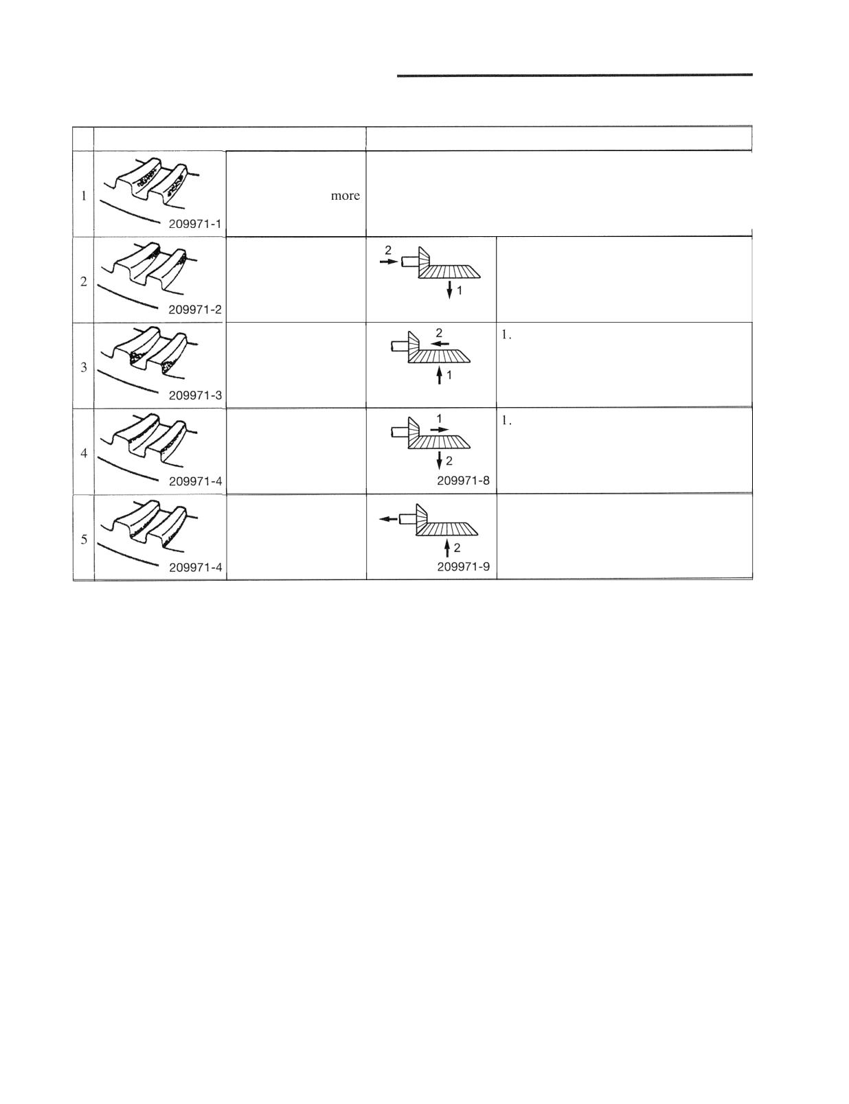
Tooth Contact Patterns and Adjustment
Tooth contact
Adjustment
Extends from toe to
middle portion,
covering 50% or
Correct tooth contact
of tooth length.
Short contact at toe of
1. Move gear away from pinion.
tooth (Toe)
2. Move pinion toward gear for correct
backlash by increasing shim thickness.
209971 -6
Short contact at heel
Move gear toward pinion.
of tooth (Heel)
2. Move pinion away from gear for correct
backlash by decreasing shim thickness.
209971 -7
Heavy contact on face
Move pinion toward gear by increasing
or top half (addendum)
shim thickness.
of tooth (Face)
2. Move gear away from pinion for correct
backlash.
Heavy contact on
1
1. Move pinion away from gear by
bottom half
decreasing shim thickness.
(addendum) of tooth
2. Move gear toward pinion for correct
(Flank)
backlash.
Note: For "Toe" or "Heel" contact, see the contact pattern on the outside (convex) of the reduction gear tooth. In the
case of "Face" or "Flank" contact, repeat the above adjustment until the correct tooth contact is obtained.
FRONT AXLE AND REDUCTION DIFFERENTIAL
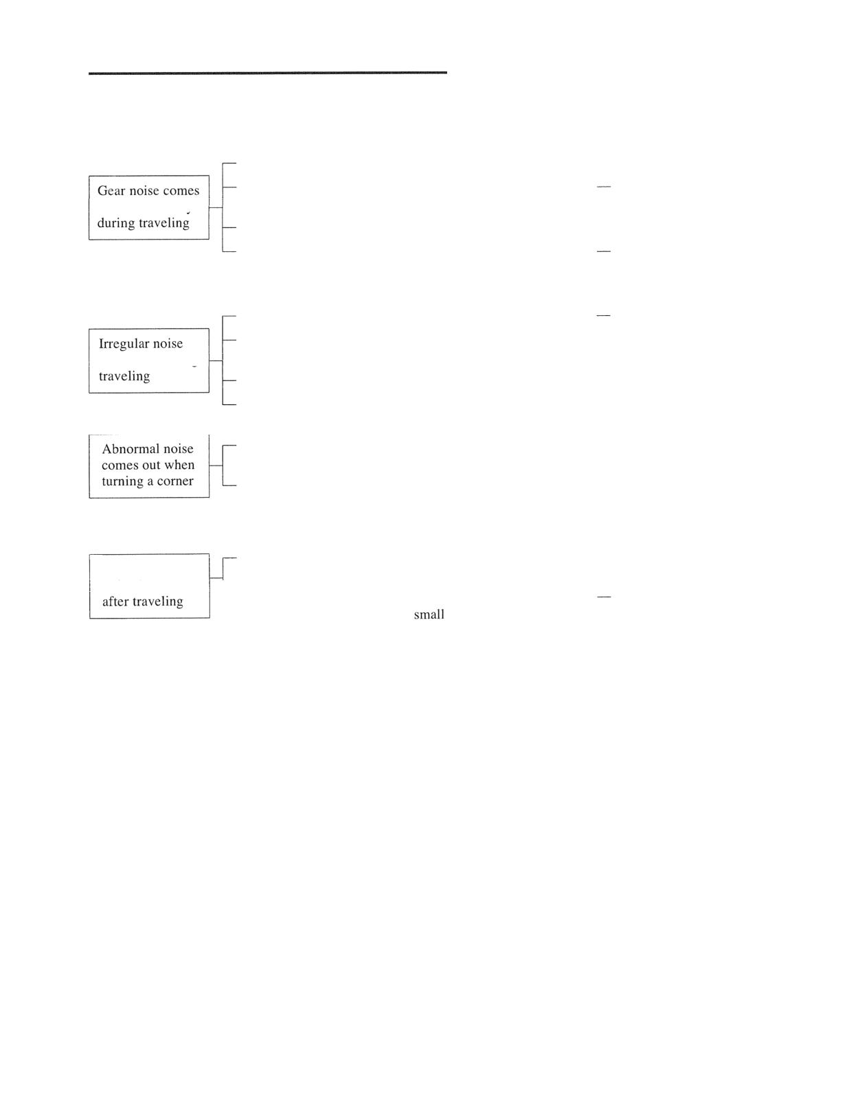
Troubleshooting
Reduction bevel gear teeth badly worn
- Replace.
Bearing preload too much or too little, or bearings worn
Readjust or replace.
out continuously
excessively
Hub bearings damaged
- Replace.
Improper tooth contact between reduction bevel pinion
Readjust.
and reduction gear
Reduction taper roller bearings or hub bearings broken
Replace.
Differential gears having broken teeth, or thrust washers
- Replace gears or washers.
comes out during
worn
Foreign substance in axle housing
- Clean and replace oil.
Bolts securing axle shaft or differential carrier
- Retighten.
Fit of differential gears in differential case out of
- Replace worn parts.
specification due to wear
r damaged byaw
eetg
broorpor seized on spider,
- Replace defective parts.
Bearings damage due to excessive preload
- Replace bearings and
Overheated
readjust preload.
reduction case
Backlash between reduction bevel pinion (on output shaft)
Readjust tooth contact
and reduction bevel gear too
and backlash.
FRONT AXLE AND REDUCTION DIFFERENTIAL
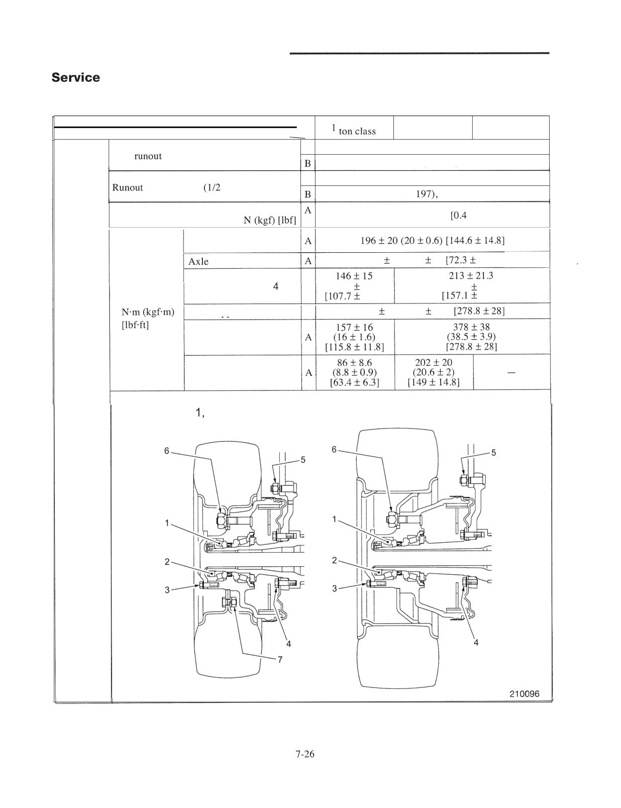
Data
A: Standard value B: Repair or service limit
Unit: mm (in.)
Truck Models
2 ton class
3 ton class
Items
A
0.08
(0.0031)
Face
of axle shaft flange
0.5
(0.0197)
A
0.5
(0.0197)
of Axle shaft
of gauge reading)
0.5
(0.0
maximum
Preload for hub bearing 1
0.5 to 4.9 (5 to 50)
to 3.61
Hub bearing lock nuts
(outer) 2
shaft bolts 3
98
9.8 (10
1)
7.21
Tightening
Backing plate bolts
A
(14.9
1.5)
(21.7
2.2)
11.11
15.71
torque
Axle support nuts 5
A
378
38 (38.5
3.9)
Wheel nuts 6
Rim bolts 7
2 ton classes
3 ton class
Hub and
wheels
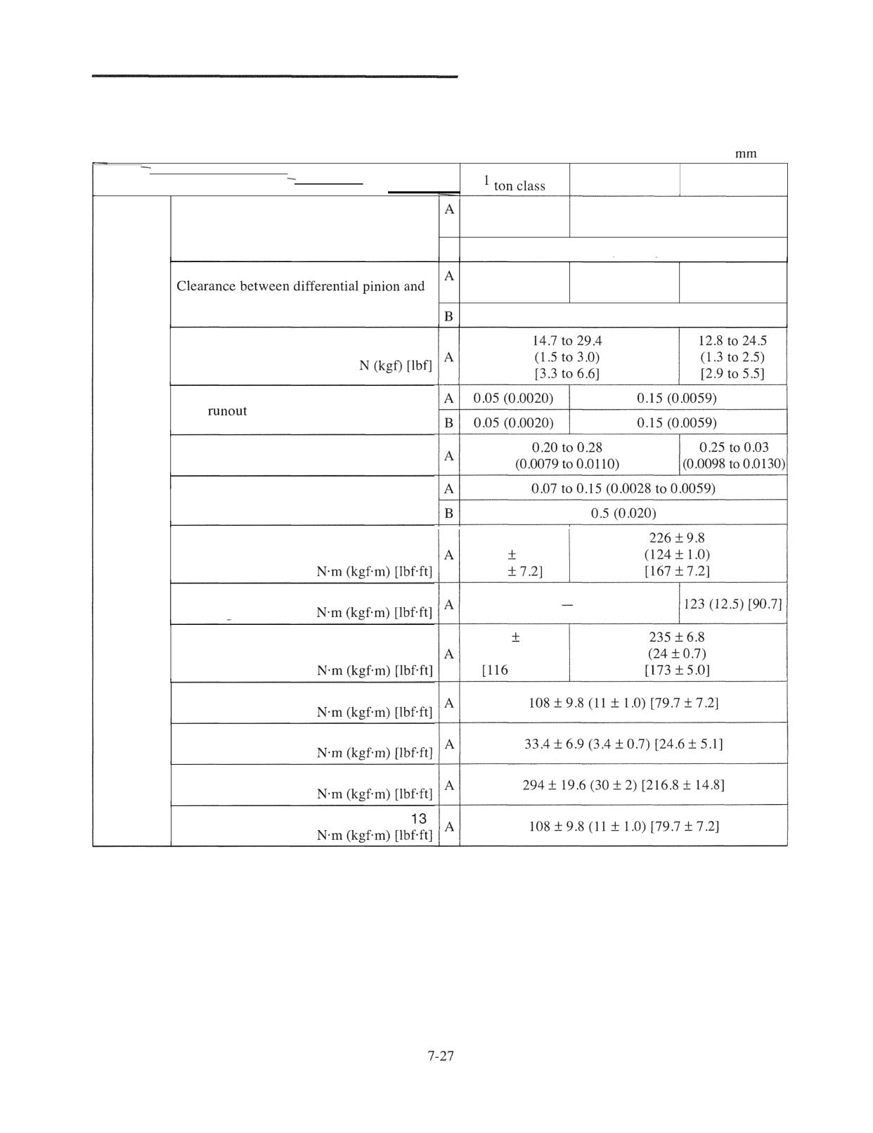
FRONT AXLE AND REDUCTION DIFFERENTIAL
A: Standard value B: Repair or service limit
Unit:
(in.)
Truck Models
2 ton class
3 ton class
-------
Items
I
0.16 to 0.30
0.15 to 0.25
(0.0063 to 0.0118)
(0.0059 to 0.0099)
Backlash of reduction differential gear 1
B
0.5
(0.0197)
0.02 to 0.07
0.02 to 0.09
0.17 to 0.27
(0.0079 to 0.0028)
(0.0079 to 0.0035)
(0.0067 to 0.0106)
spider 2
0.35
(0.0138)
Preload for differential case side bearing 3
Face
of reduction bevel gear 4
Backlash of reduction bevel gear and
pinion 5
Free play of gear and shaft spline 6
Reduction
differential
Tightening torque of reduction bevel gear
118 19 .8
mounting bolts 7
(12
1.O)
[87
Tightening torque of differential case
mounting bolts 8
Tightening torque of side bearing cap
157
5.9
bolts 9
(16 10.1)
14.41
Tightening torque of differential carrier
bolts 10
Tightening torque of differential carrier
cover bolts 1 1
Tightening torque of lock nut 12
Tightening torque of input flange bolts
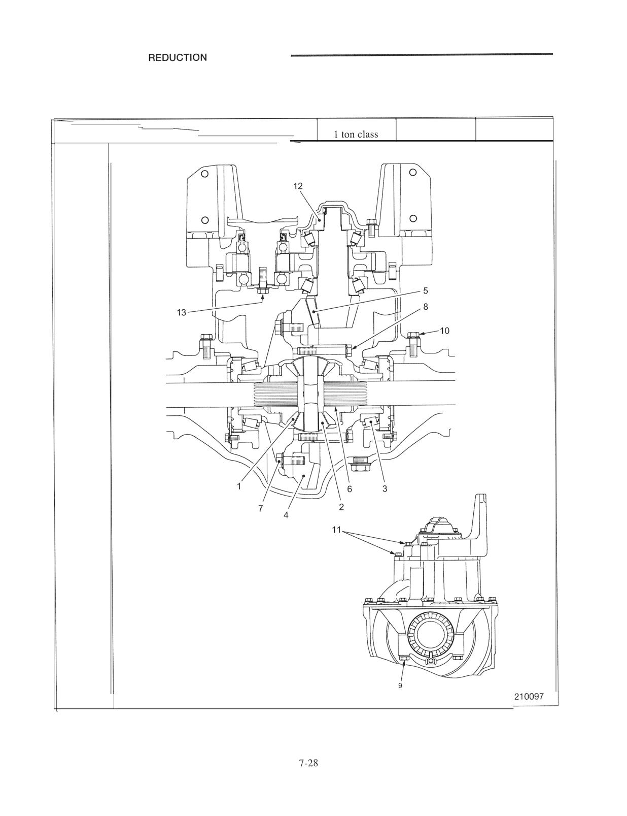
FRONT AXLE AND
DIFFERENTIAL
A: Standard value B: Repair or service limit
Unit: rnrn (in.)
Truck Models
2 ton class
3 ton class
Iterns
Reduction
differential
REAR AXLE
structure and Functions
8
1
Rear Axle in General
8
1
Structure of Each Component
8 -
2
Steering Cylinder
8 -
3
Removal and
8 -
Rear Wheel and Rear Axle Assembly
8 -
4
Disassembly
and Reassembly
8 -
1. Disassembly and Reassembly of Wheel Hub
8 -
5
2. Disassembly and Reassembly of Knuckle (King Pin)
8 -
7
3. Disassembly and Reassembly of Steering Cylinder
8 -
9
4. Disassembly and Reassembly of Tie Rod
8 - 10
AXLE
Structure and Functions
Rear Axle in General
---
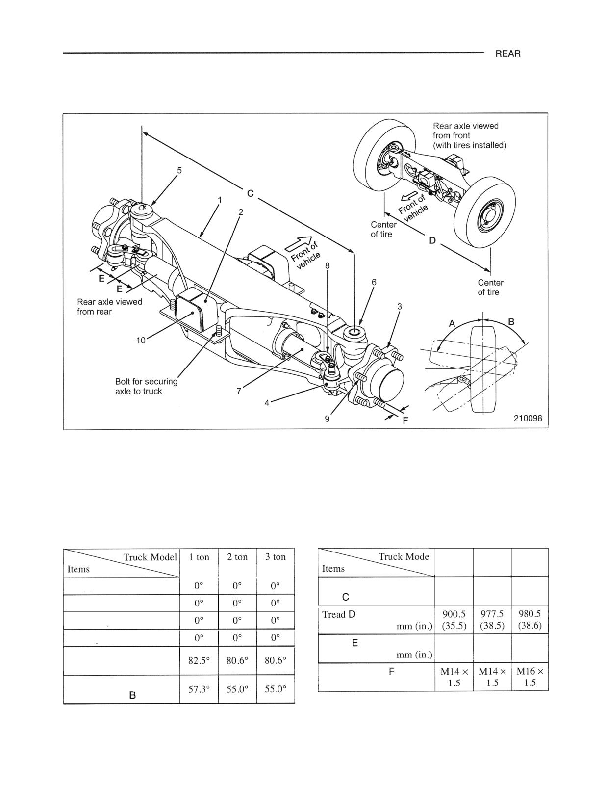
Main Components
1 Rear axle main unit
6 Right-side king pin (with tire angle sensor)
2 Mount bushing (rear axle support)
7 Steering cylinder
3 Wheel hub
8 Tie rod
4 Knuckle
9 Wheel bolt
5 Left-side king pin
10 Rubber shim (rear of vehicle only)
Specifications for wheel alignment and steering angle
I
1 ton
2 ton
3 ton
class
class
class
class
class
class
-
-
-
King pin inclination angle
Distance between king
740
818
818
pins
mm (in.)
(29)
(32)
(32)
Camber angle
Caster angle
Toe angle
Stroke
83.5
98.5
98.5
Maximum steering angle
(3.29)
(3.88)
(3.88)
of inner wheel A
Wheel bolt size
Maximum steering angle
of outer wheel
Note: The steering angle is automatically determined by stroke of the steering cylinder. It is not structured to be
changed by adjustment.
8-1
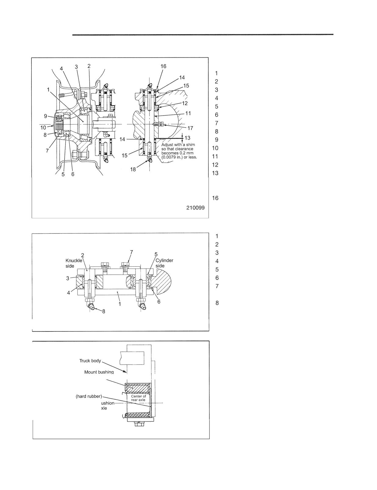
REAR AXLE
Structure of Each Component
Main components of wheel hub
Spindle of knuckle
Oil seal
Bearing cone (inner race)
Cup (outer race)
Bearing cone (inner race)
Cup (outer race)
Nut (hexagon nut)
Lock plate
Bolt
Hub cup
Left-side king pin
Thrust bearing
Shim (for adjusting clearance)
14
Dust seal
Detail of wheel hab
Detail of king pin
15
Needle bearing
King pin cover
17
Bolt, Nut (for securing king pin)
18
Grease nipple
Tie rod
Tie rod pin
Dust seal
Bushing
Retainer
Dust seal
Bolt and washer
assembly
Grease nipple
Detail of tie rod
209688
I
(rubber),
i
Rubber shim
This acts as a c
when the rear a
moves rearward.
Center of rear axle
209689
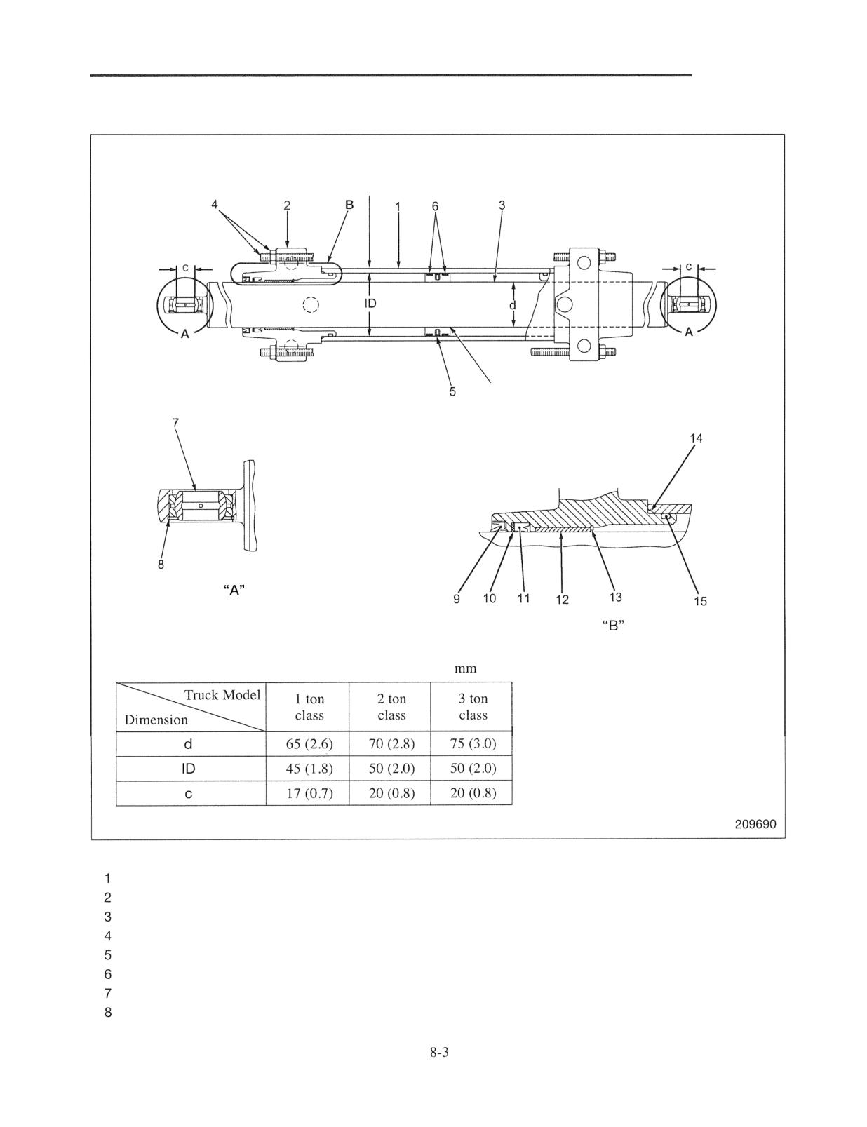
REAR AXLE
Steering Cylinder
Thickness of
5 mm (0.20 in.)
'Shrinkage fit
Detail of
Detail of
Unit:
( in.)
Dimension
Main components
Body
9 Dust seal
Header
10 Backup ring
Rod assembly
11 Rod seal
Stay rod, Nut, Washer
12 Bushing
Piston seal
13 Snap ring
Guide ring
14 O-ring
Ball joint
15 O-ring
Snap ring
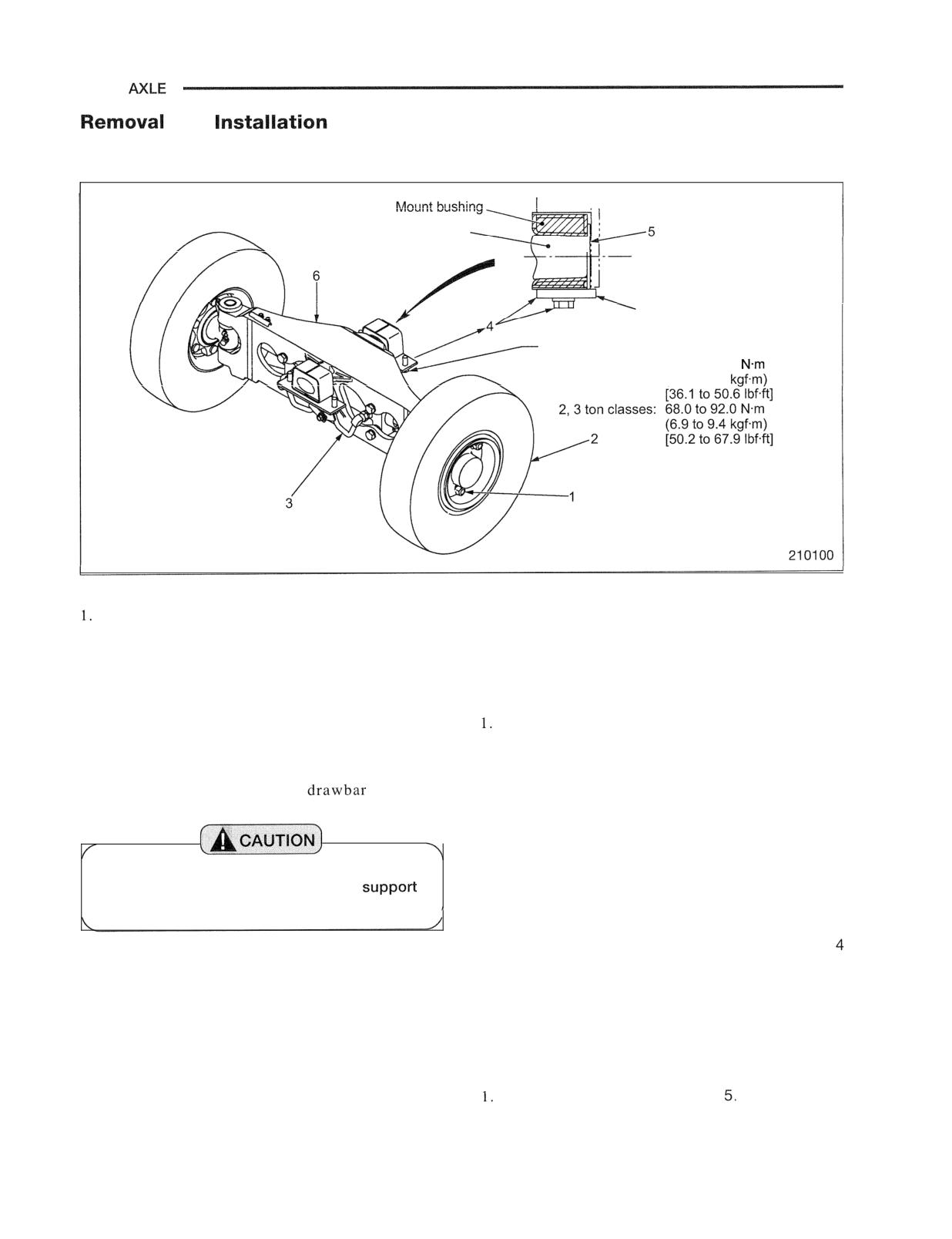
REAR
and
Rear Wheel and Rear Axle Assembly
! I
Center of rear axle
1
Stopper plate
Tightening torque of axle mounting bolt
1 ton class:
49.0 to 68.6
(5.0 to 7.0
Removal of rear wheels
Removal sequence of axle assembly
1 Wheel nut (6 pcs.)
5 Rubber shim
Set the parking brake, and block the front wheels.
2 Rear wheel
6 Rear axle (with
2. Loosen the wheel nut about two turns and raise the
3 Hose or pipe
cylinder)
rear end of the truck by using a jack or crane at the
4 Bolt, Stopper plate
specified point.
(1) Method using a jack
Suggestions for Removal
Position the jack under the counterweight at the
Refer to "Removal of rear wheels" in previous
jacking point and raise the rear tire.
pages to remove the rear wheels.
(2) Method using a crane
2. Raise the truck with a jack and support the bottom
of both sides of the frame with jack stands.
Attach lifting sling to the
pin in the
[Approx. 500 mm (19.7 in.) is sufficient for the
counterweight, and lift it.
distance between the bottom of the frame and the
ground .]
3. Disconnect the hose or pipe 3 from the cylinder
When the truck is raised by either method,
elbow (2 places). Disconnect the tire sensor
place jack stands under the frame to
it
harness from the connector.
securely.
4. Place a garage jack under the axle to support the axle.
5. Remove rear axle mounting bolts, stopper plate
3. Remove the wheels.
and rubber shim 5.
6. Lower the garage jack and pull out the rear axle
lnstallation of rear wheels
(with cylinder) from the truck.
Follow the sequence of disassembly in reverse.
lnstallation
Note: Tighten wheel nuts evenly to the specified
Follow the sequence of disassembly in reverse, paying
torque.
attention to the following points.
Be sure to insert the rubber shim
2. Tighten bolts 4 to the specified torque.
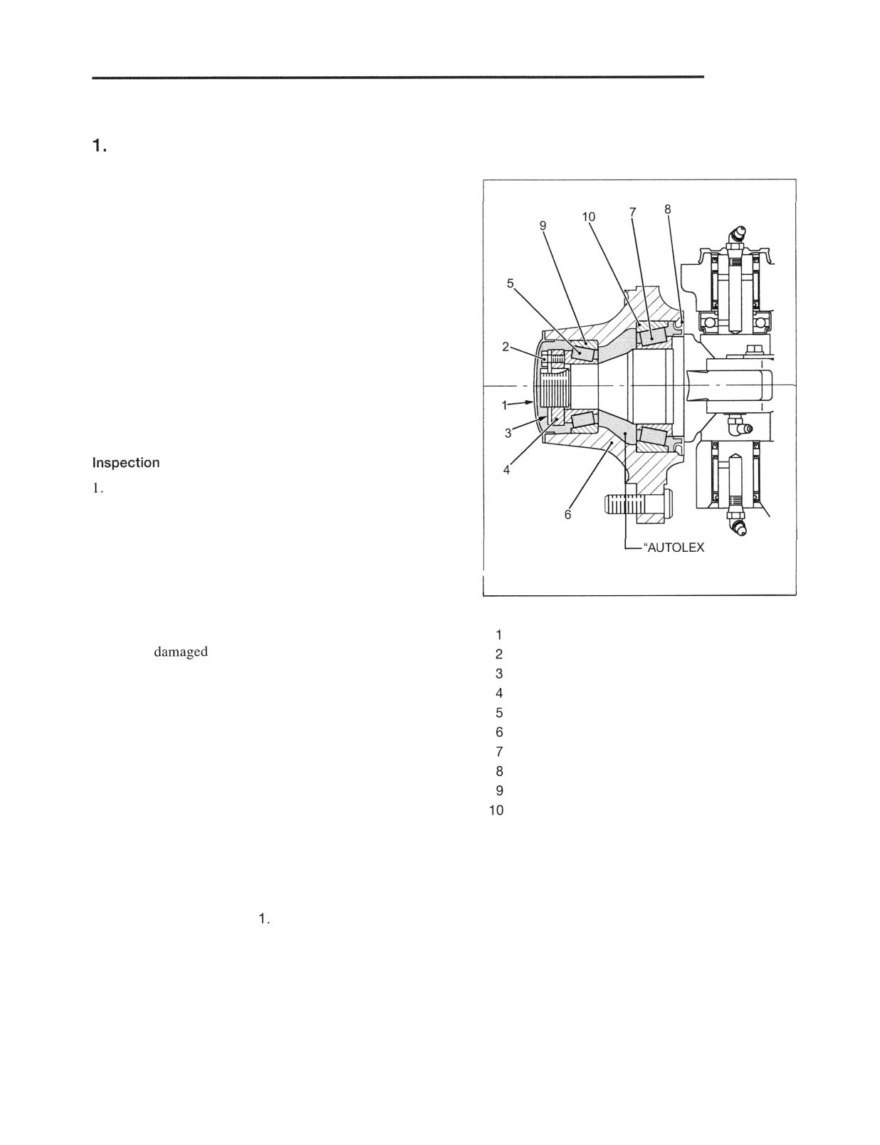
REAR AXLE
Disassembly and Reassembly
Disassembly and Reassembly of Wheel Hub
Suggestions for Disassembly
1. Remove rear wheels as preparatory work.
2. Check the hub for looseness. If there is looseness, the
bearing may be worn.
3. If the bearing is not damaged, it is not necessary to
remove it.
4. The cup and the cone of the bearing make a pair. When
replacing, replace them as a set.
5. When removing the oil seal 8, replace it with a new
one. Do not reuse it.
6. Use a special service tool to remove the bearing.
after disassembly
Bearing
Replace the bearing with a new one if damage, seizure,
peel, rotation failure or abnormal noises are found.
A grease
2. Hub
Replace the hub with a new one if cracks are detected by
209692
dye check.
Disassembly sequence
3. Oil seal
Hub cup
Replace a
or worn oil seal with a new one.
Bolt
Lock plate
Lock nut (hexagon nut)
Reassembly
Bearing cone
Follow the sequence of disassembly in reverse, paying
Hub (with bearing cup)
attention to the following points.
Bearing cone
1. Fill "AUTOLEX A" grease or equivalent wheel bearing
Oil seal
grease in the shaded area in the illustration on the right.
Bearing cup
Be careful to sufficiently fill it in the roller retainer.
Bearing cup
Apply grease also to the oil seal lip groove.
2. Adjust the bearing. Refer to "Adjusting procedure of
wheel bearing reassembly" on the following page.
3. Fill grease in the inside of the hub cup 1 before
pushing in the hub cup
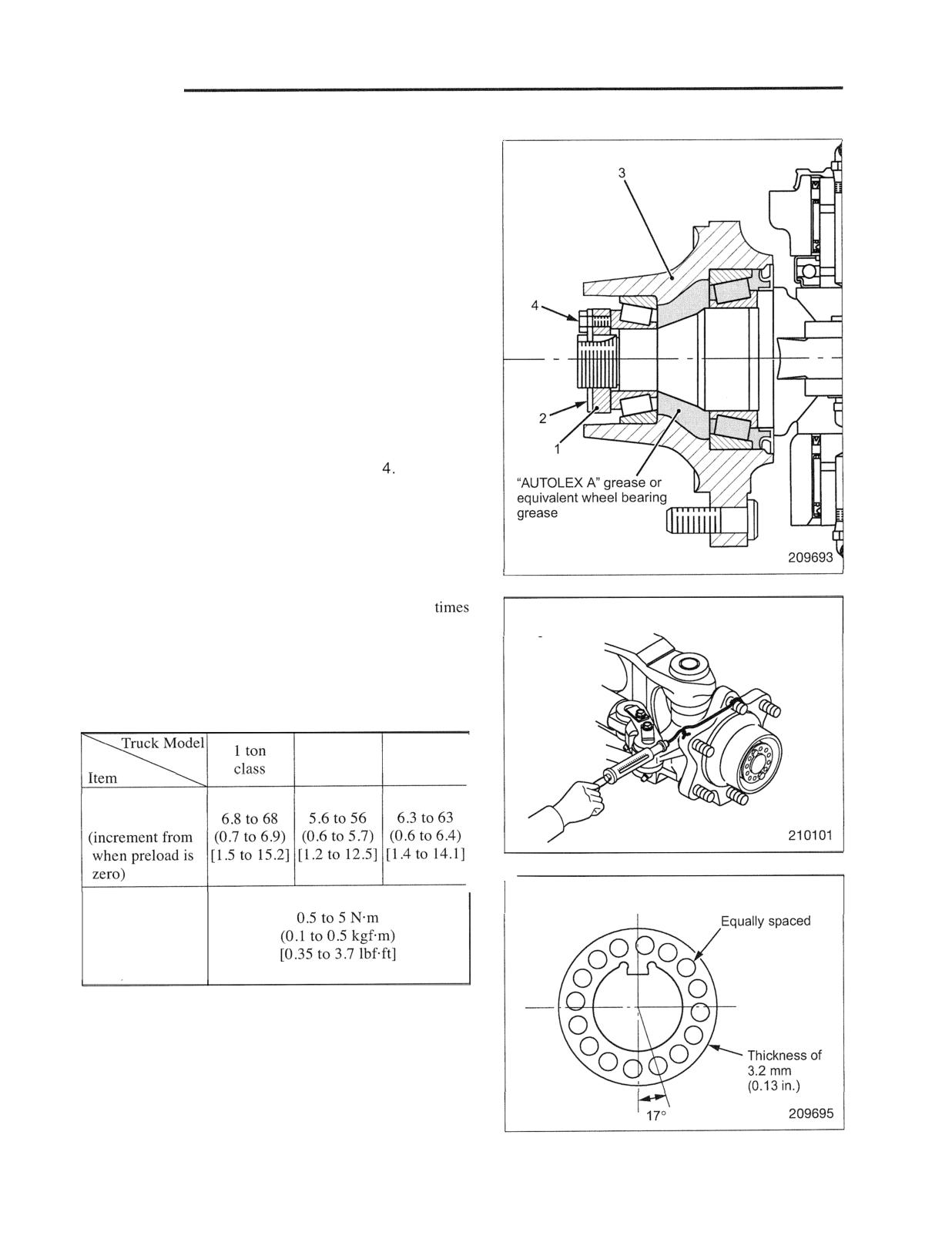
REAR AXLE
Adjusting procedure of wheel bearing reassembly
1. Apply oil or grease to the contact surface of the lock
nut 1 with the wheel bearing.
2. Turn the wheel hub 3 by hand and tighten the lock nut
1 until the turn becomes difficult. Then, loosen the
lock nut by approx. 60 degrees from the position.
3. Turn the rear wheel hub back and forth two to three
times in the above condition to settle the cup and cone
of the wheel bearing.
4. Turn the wheel hub 3 by hand again and tighten the
lock nut 1 until the turn becomes heavy.
5. Insert the tab of the lock plate 2 aligning with the
knuckle groove and gradually loosen the lock nut 1
until the hole position of the lock plate 2 aligns with
the screw position of the lock nut 1. Then, secure the
lock nut 1 and lock plate 2 with two bolts
Note: Reversing the lock plate 2 changes the hole position.
(See the illustration on the right.)
6. Turn the wheel hub back and forth two to three
Measurement of
and make sure that the rotational driving force or
tangential force
starting tangential force is within the range below. If
out of the range, readjust. In case of a long-used
bearing, aim a low value of the allowance.
Unit: N (kgf) [lbf]
2 ton
3 ton
class
class
Tangential force
of hub bolt
Lock plate shape
Hole of 6.5 mm
Starting torque of
(0.26 in.)
hub rotation
(increment from
when preload is
zero)
No looseness is allowed in the axial direction.
8-6
REAR AXLE
Disassembly and Reassembly of Knuckle (King Pin)
Suggestions for Disassembly
Start by:
(a) Remove rear wheels.
(b) Remove wheel hubs
Separation of tie rod
1. For only separating the knuckle from the tie rod,
remove the bolt washer assembly 1 and spacer 2 on the
knuckle and pull out the tie rod pin 3.
2. Further disassemble to implement a full overhaul. For
details, see the page 10-10.
Removal of king pin
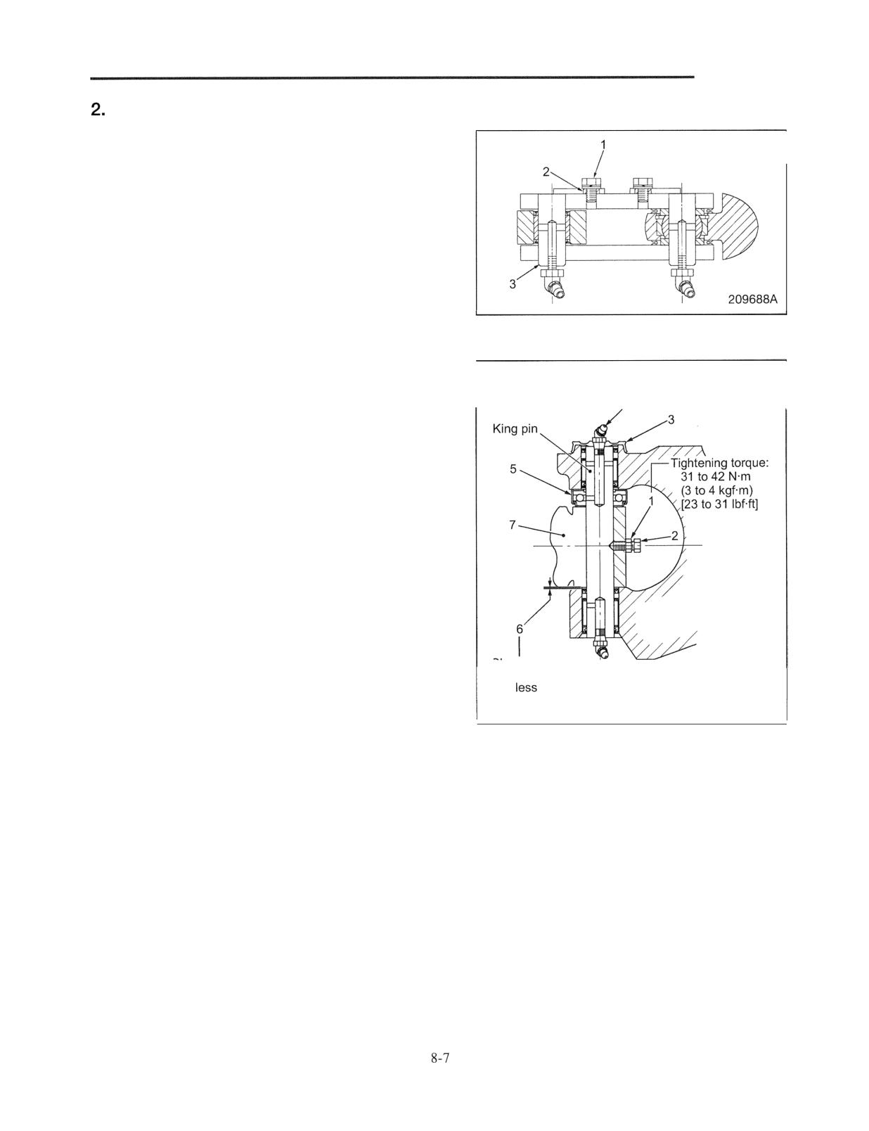
Left-side king pin
1. Loosen the lock nut 1 and remove the stopper bolt 2.
4
2. Remove the king pin cover 3 and grease nipple 4.
3. Apply a soft metal piece to the king pin from above
and drive the king pin downward. Support the king pin
by hand so that it will not fall down.
4. Remove the thrust bearing 5 , shim 6 and knuckle 7.
5. Pull out the dust seal and needle bearing from the rear
axle body as necessary.
Inspection after disassembly
Clean and inspect disassembled parts.
Needle bearing and thrust bearing: Replace the bearings
with new ones if damage, seizure, peel, rotation failure or
abnormal noises are found.
Clearance:
0.2 mm (0.0079 in.)
Dust seal: Replace a damaged or worn seal with a new
or
one.
210102
I
I
Reassembly
Follow the sequence of disassembly in reverse, paying
attention to the following points.
1. Reassemble the king pin inserting from the lower side
toward the upper side. (Reassembly in the opposite
direction may damage the shim 6.)
2. Reassemble the thrust bearing 5 in the direction as
illustrated. Adjust with a shim 6 so that clearance in
the axial direction becomes 0.2 mm (0.0079 in.) or less.
3. When replacing the dust seal and needle bearing, install
them to the direction and dimensions as shown in the
illustration on the right using a driving tool.
4. Apply a sufficient amount of grease after reassembly.
Apply grease until it comes out of the boundary
between the axle and the knuckle.
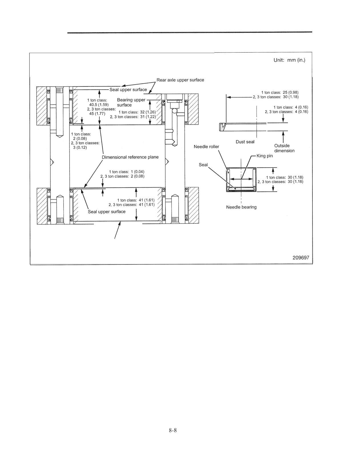
REAR AXLE
5. Dimensions after disassembly are shown below.
Left-side king pin
Right-side king pin
(with sensor)
Bearing lower surface
REAR AXLE
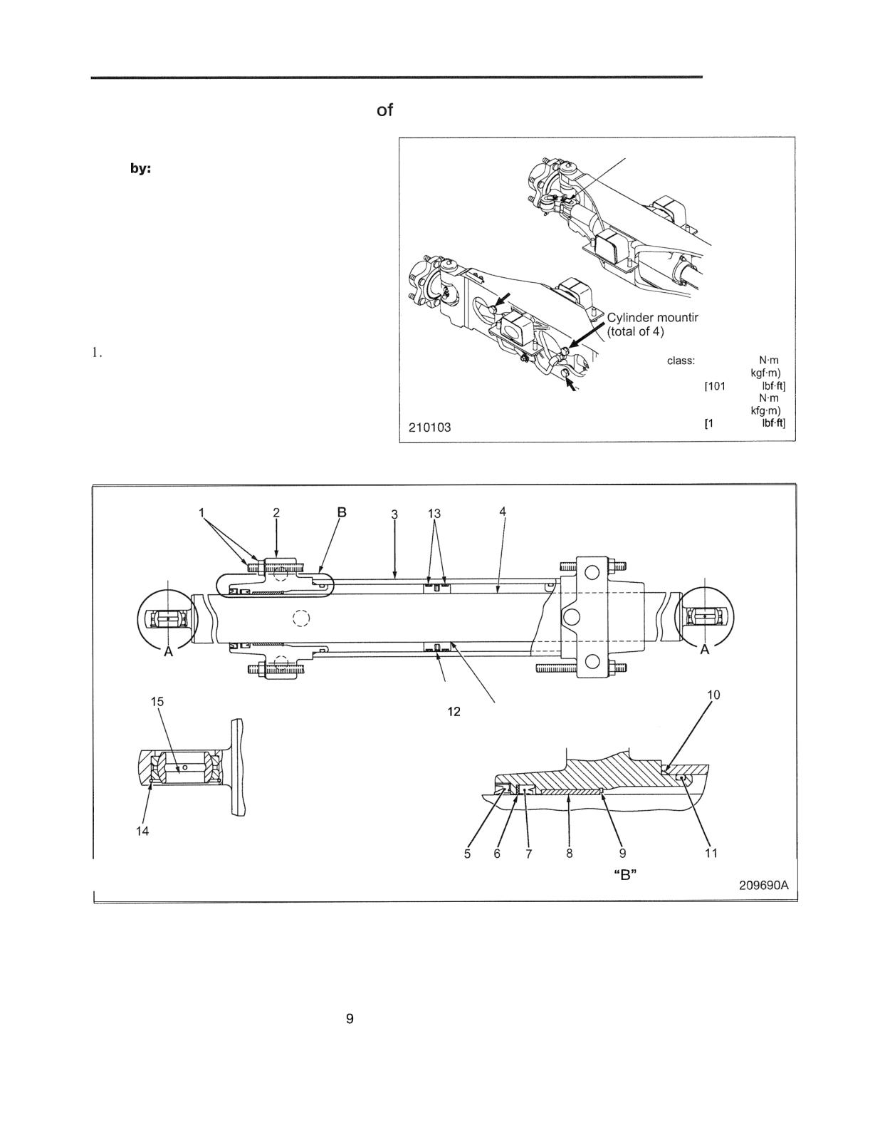
3. Disassembly and Reassembly Steering Cylinder
Removal
,Tie rod pin
Start
(a) Remove the rear axle assembly (with
cylinder) from the truck.
(b) Pull out right and left tie rod pins on the
cylinder to disconnect the knuckle from
the cylinder.
g bolt
Removal of cylinder
Tightening torque:
Remove cylinder mounting bolts (4 pcs.)
1
ton
137 to 186
to remove the steering cylinder.
(14 to 19
to 137
2, 3 ton classes: 265 to 292
(27 to 30
95 to 215
Disassembly of steering cylinder
\
Shrinkage fit
Detail of "A1"
Detail of
Sequence
1 Stay rod, Washer and Nut
5 Dust seal
11 O-ring
2 Header (with parts 5 through
6 Backup ring
12 Piston seal
10 assembled)
7 Rod seal
13 Guide ring
3 Body
8 Bushing
14 Snap ring
4 Rod assembly (with parts 12
Snap ring
15 Bail joint
through 1 5 assembled)
10 O-ring
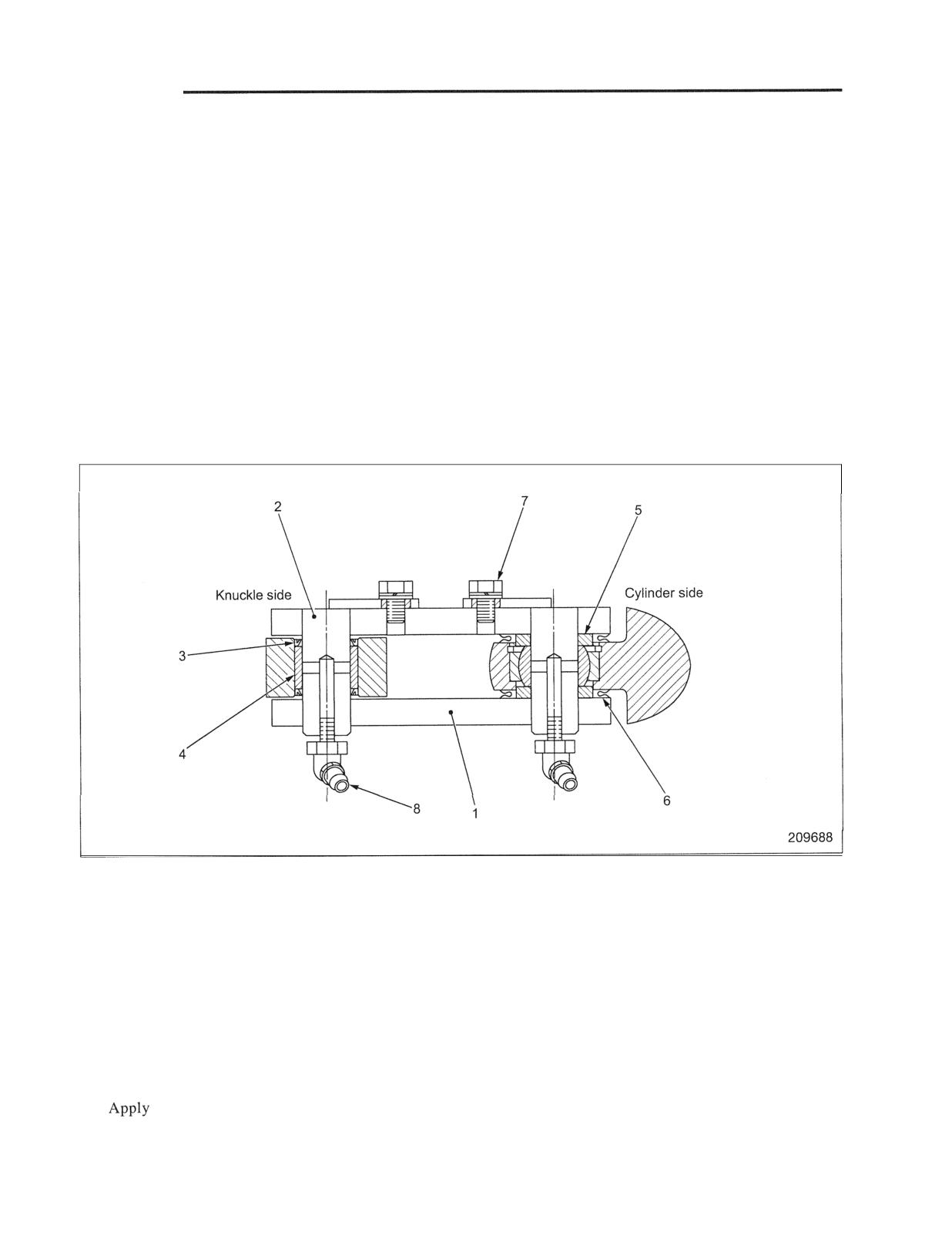
REAR AXLE
Suggestions for Disassembly
Reassembly
1. Activate the piston by blowing compressed air from
Follow the sequence of disassembly in reverse, paying
the oil port to discharge oil in the inside.
attention to the following points.
2. When the stay rod 1 is removed, the cylinder is
1. Reassemble in a clean place where no dust or
divided into three parts.
abrasive foreign substance enters.
3. Remove damaged or worn seals as necessary. Do
2. Reassemble parts while lubricating them with
not reuse removed seals.
hydraulic oil.
3. Replace seal kit parts with new ones as much as
possible.
4. Be careful not to twist O-rings when installing.
4. Disassembly and Reassembly of Tie Rod
Disassembly
Sequence
1 Grease nipple
5 Retainer
2 Bolt and washer assembly
6 Dust seal
3 Spacer
7 Dust seal
4 Tie rod pin
8 Bushing
Reassembly
Follow the sequence of disassembly in reverse, paying
attention to the following points.
1. Replace a damaged or worn dust seal with a new one.
2.
sufficient amount of grease after reassembly.
Apply grease until it comes out of the dust seal.
BRAKE SYSTEM
9
1
Brake System
9 -
1
Disassembly and Reassembly
-
Master Cylinder
9 -
2
Disassembly
9 -
2
Reassembly
9 -
3
Wheel Brakes
9 -
4
Disassembly
9 -
6
Reassembly
9 -
9
Wheel
Cylinder
9 - 12
Disassembly
9 - 12
Reassembly
9 - 13
Inspection and Adjustment
- 14
Automatic Adjuster Test
9 - 14
Manual Adjustment
9
14
Parking
Brake Cable Adjustment
9
15
Brake Pedal Adjustment
- 16
Bleeding Brake Lines
17
Braking Performance Test
9 - 17
Parking
Brake Lever
9 - 18
Troubleshooting
19
Data
BRAKE SYSTEM
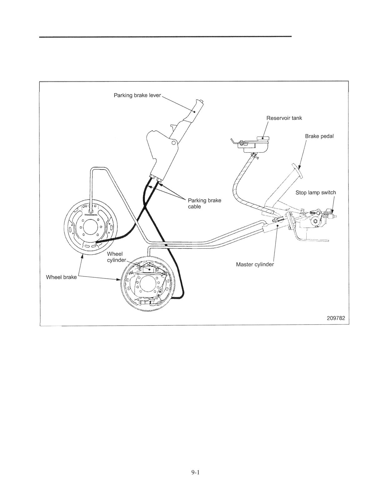
Structure
Brake System
BRAKE SYSTEM
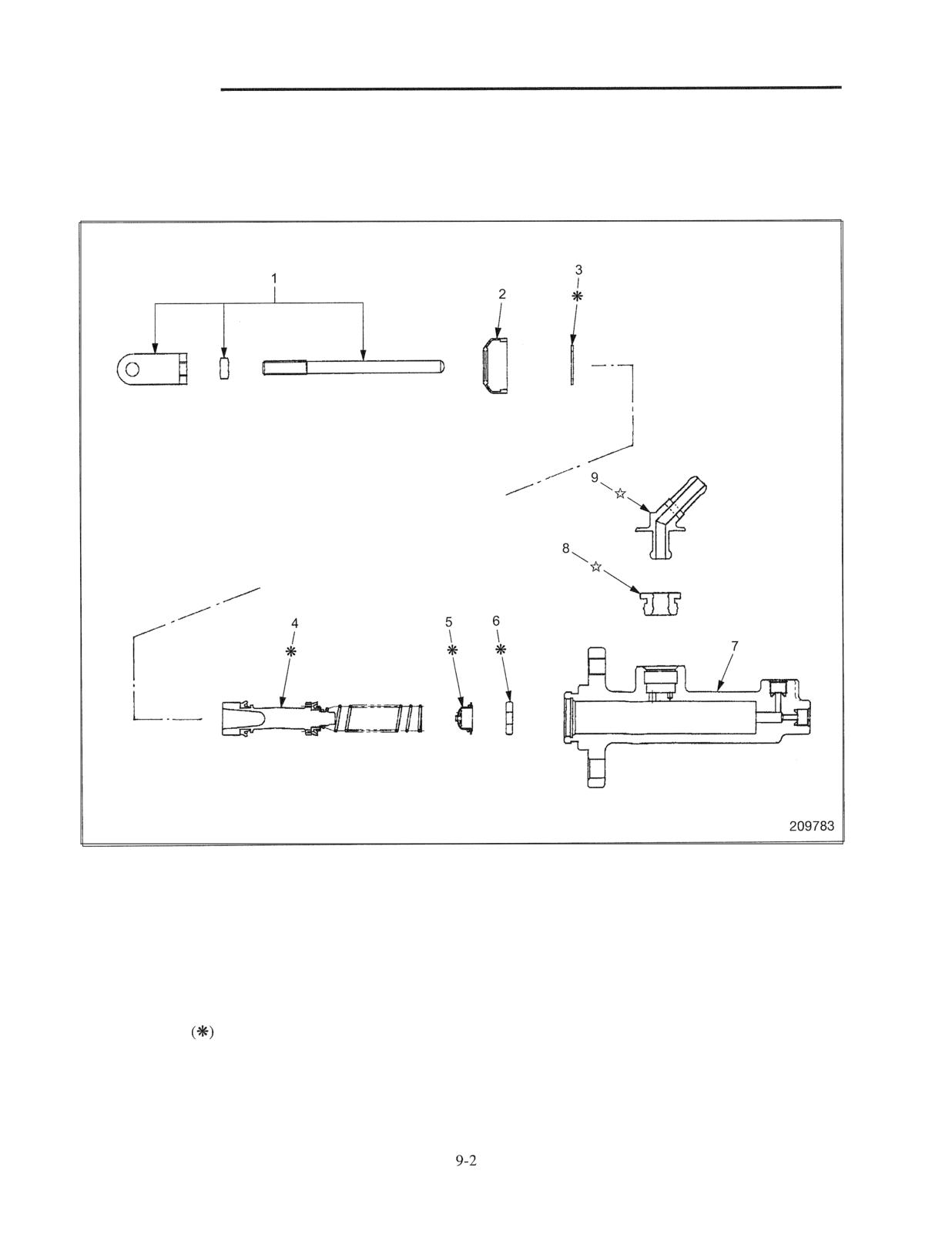
Disassembly and Reassembly
Master Cylinder
Disassembly
Sequence
1 Clevis, Nut, Push rod
6 Valve seat
2 Boot
7 Cylinder
3 Snap ring
8 Bushing
4 Piston assembly
9 Filler union
5 Valve assembly
Note: The parts
and (b) to be changed periodically are included in the Repair Kit.
BRAKE SYSTEM
Inspection after disassembly
Cylinder
Check the cylinder bore for rusting, erosion, abnormal
or
(2) Check the inlet and relief ports for restriction. Check
the threads on each joint for damage. Also, check the
boot and other parts for damage.
2. Piston
Check the piston for damage. Replace if it is damaged.
Insert the piston into the cylinder, and measure the
to-cylinder clearance. If the clearance is in excess of the
service limit, replace the cylinder and piston.
A: Standard value
B: Service limit
0.020 to 0.105 mm
Clearance between
(0.00079 to 0.00413 in .)
cylinder and piston
B
0.15 mm (0.0059 in.)
3. Return spring
Replace the spring if it is severely damaged or its free
length is at or less than the service limit.
A: Standard value
Service limit
Spring free length
B
53.9
(2.1 in.)
4. Cups in piston assembly
Check the rubber parts for damage or swelling. If the lips
are damaged even slightly, the base is bitten, or abnormal
fatigue, wear or swelling is evident, replace the piston
assembly. If the cup tightness is 0.4 mm (0.0157 in.) or
less, replace the piston assembly.
Note: The cups must be replaced periodically. It is a safe
and good practice to replace
whenever the
master cylinder is disassembled.
Reassembly
To reassemble, follow the disassembly procedure in
reverse, paying attention to the following points.
(I)
all metal parts with volatile cleaning solvent, and
completely dry them with compressed air.
(2) Apply a thin coat of rubber grease exclusively designed
for brake components or brake fluid to the cylinder
bore, piston CUPS, and the inner face of the filler union
bushing mounting hole.
BRAKE SYSTEM
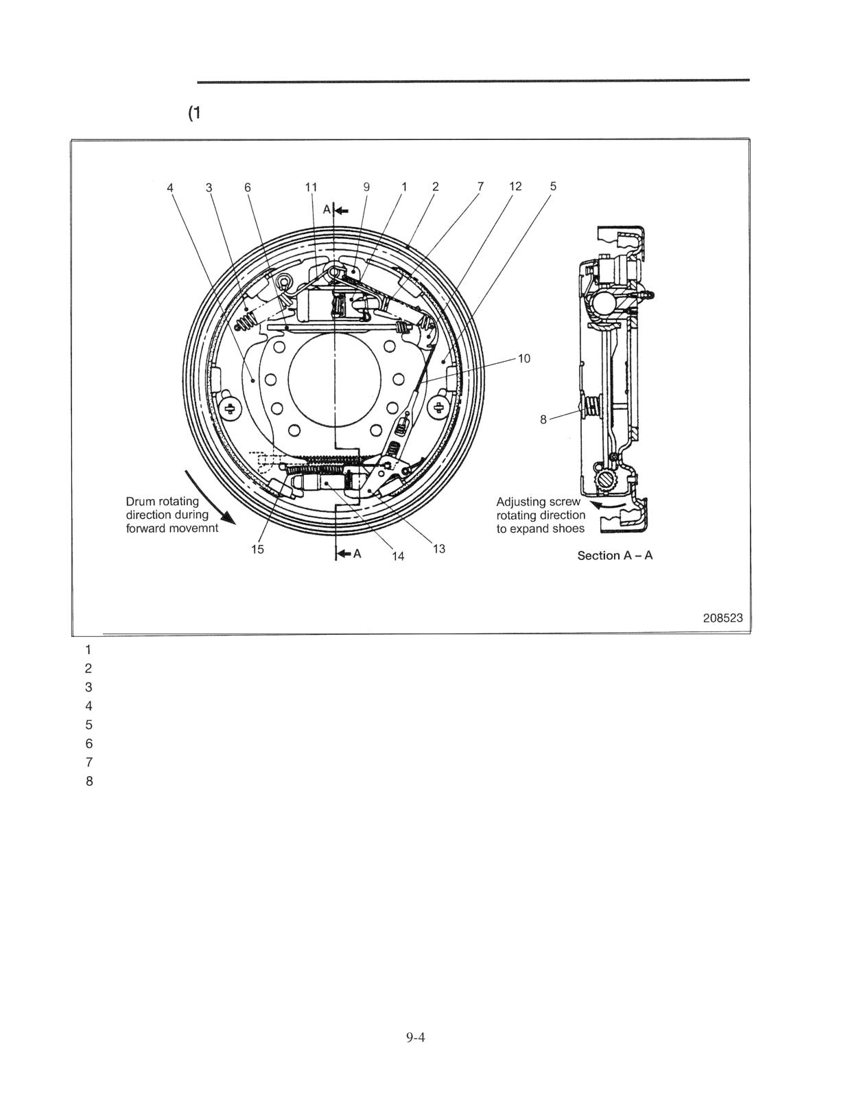
Wheel Brakes ton class)
The illustration shows a left-hand wheel brake.
Wheel cylinder
9 Shoe guide plate
Backing plate
10 Cable with spring
Shoe and lining (primary)
11 Return spring
Parking brake lever
12 Sheave
Shoe and lining (secondary)
13 Adjusting lever
Strap
14 Adjusting screw
Return spring
15 Return spring
Hold-down spring
BRAKE SYSTEM
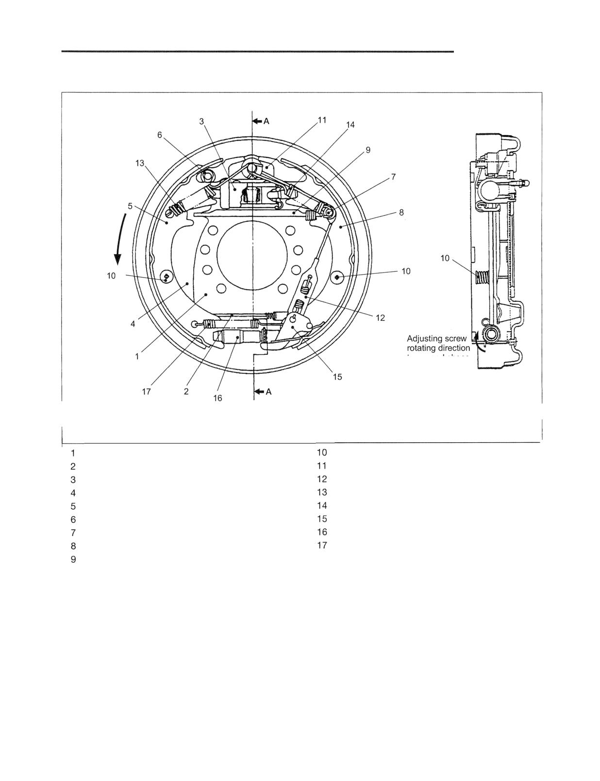
Wheel Brakes (2, 3 ton classes)
Drum
rotating
direction
during
forward
movement
-
to expand shoes
Section A - A
The illustration shows a left-hand wheel brake.
209784
Backing plate assembly
Pin, Hold-down spring, Cup
Parking brake cable, Snap ring
Shoe guide plate
Wheel cylinder
Cable with spring
Parking brake lever
Return spring (primary)
Primary shoe and lining assembly
Return spring (secondary)
Retainer, Washer
Adjusting lever, Adjusting spring
Pin, Sheave, Washer
Adjusting screw
Secondary shoe and lining assembly
Return spring
Strut, Anti-rattle spring
BRAKE SYSTEM
Wheel Brakes
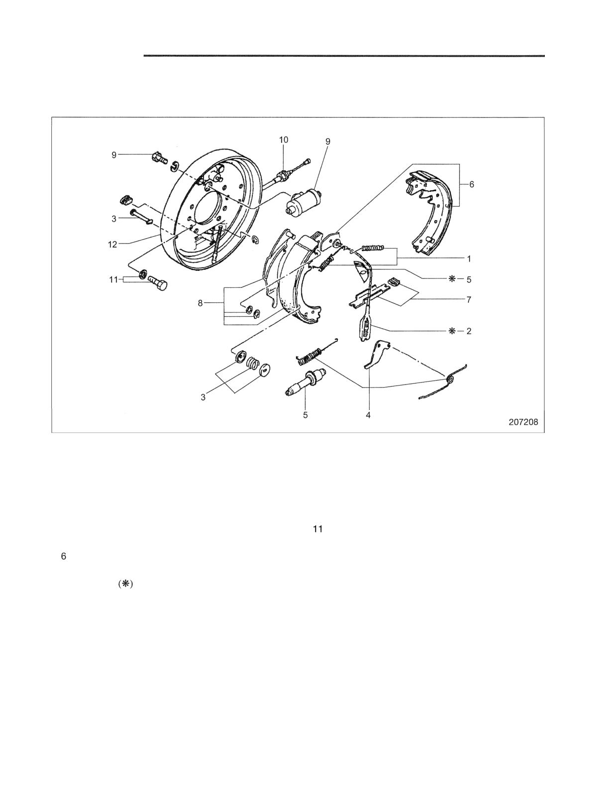
Disassembly
Sequence
1 Return spring
7 Strap, Anti-rattle spring
2 Cable with spring
8 Shoe and lining (primary), Parking brake lever,
3 Hold-down spring, Cup, Pin
Retainer, Spring washer
4 Adjusting lever, Adjusting spring, Return
9 Wheel cylinder
spring
10 Parking brake cable
5 Cable guide, Sheave, Adjusting screw, Pin,
Mounting bolt, Spring washer
Washer
12 Backing plate
Shoe guide plate, Shoe and lining (secondary)
Note: The part
to be changed periodically are included
in the Brake Repair Kit.
Start by:
(a) Remove the front wheel.
(b) Remove the wheel hub and brake drum.
(c) Separate the parking brake lever and cable at the
bottom of wheel brake.
(d) Disconnect the brake pipe from the wheel brake
assembly.
BRAKE SYSTEM
Suggestions for Disassembly
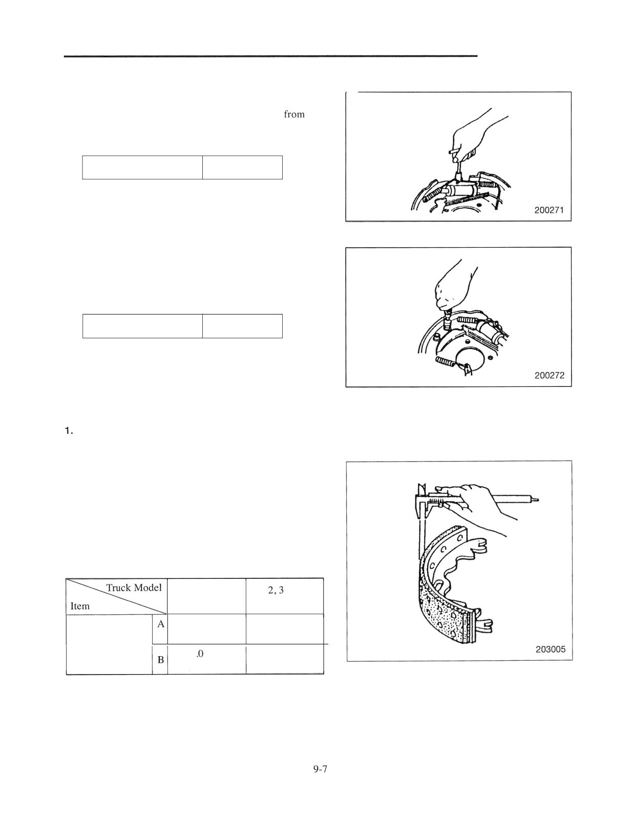
1. Removing return springs
Use a special tool to remove the return springs
the
shoe guide plates.
Special tool needed
Spring remover
64309 - 15411
2. Removing hold-down springs
Use a special tool to remove the hold-down springs from
the backing plate.
Special tool needed
Spring retainer
64309 - 15412
Inspection after Disassembly
Backing plate
(1) Check the backing plate for cracks.
2. Shoes and lining
(1) Check each shoe and lining for cracks.
(2) Replace the lining if it is heavily fouled with grease,
burnt or otherwise deteriorated.
(3) Measure the thickness of the lining. Replace if it is
worn to less than the service limit.
A: Standard value
B: Service limit
1 ton
ton
class
classes
4.87 mm
5.7 mm
(0.19 in.)
(0.22 in.)
Thickness of
lining
1 mm
1.0 mm
(0.04 in.)
(0.04 in.)
BRAKE SYSTEM
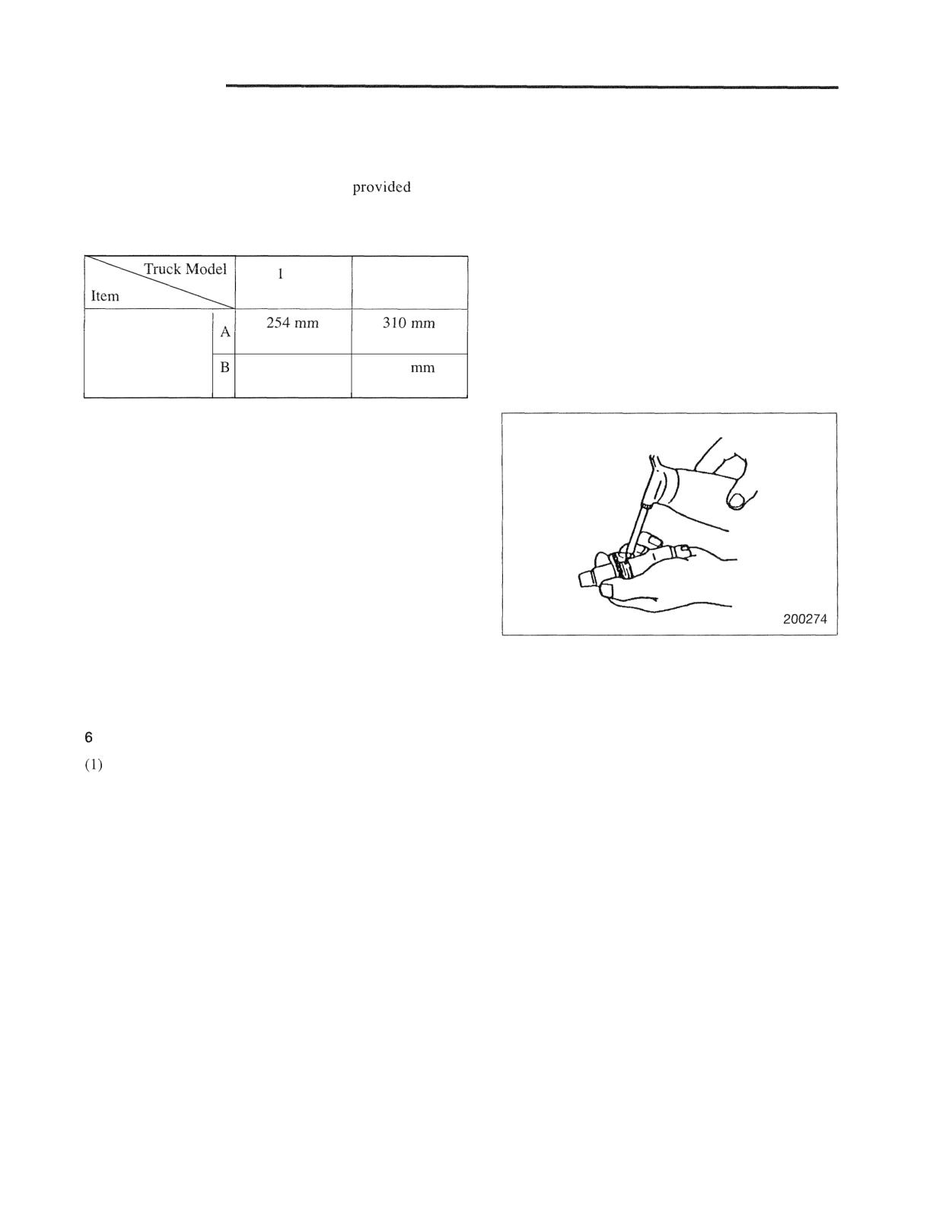
3. Brake drums
Check the inside (friction) surface of the drum for
abnormal wear, grooving and other defects. Minor
grooving can be removed by grinding,
that the
inside diameter does not exceed the service limit.
A: Standard value
B: Service limit
ton
2,3ton
class
classes
I
Inside diameter
(10.0 in.)
(12.2 in.)
of brake drum
256 mm
312
(10.1 in.)
(12.3 in.)
4. Adjusting screws
Check the wheel teeth for wear. Turn the screw by hand to
see if its rotating parts turn smoothly.
5. Parking brake cable
Replace a cable if it shows stretching, rust or damage.
Other parts
Check the shoe return springs for cracks or fatigue.
(2) Check the adjusting springs for cracks or fatigue.
(3) Check the cable with spring for stretching.
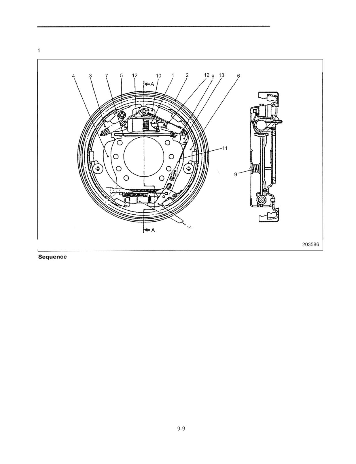
BRAKE SYSTEM
Reassembly
ton class
Section A - A
1 Wheel cylinder
9 Hold-down spring, Cup, Pin
2 Backing plate
10 Shoe guide plate
3 Shoe and lining (primary)
11 Cable with spring
4 Parking brake lever
12 Return spring
5 Retainer, Washer
13 Cable guide, Sheave, Pin, Washer
6 Shoe and lining (secondary)
14 Adjusting lever, Adjusting screw, Adjusting
7 Strap
spring
8 Anti-rattle spring
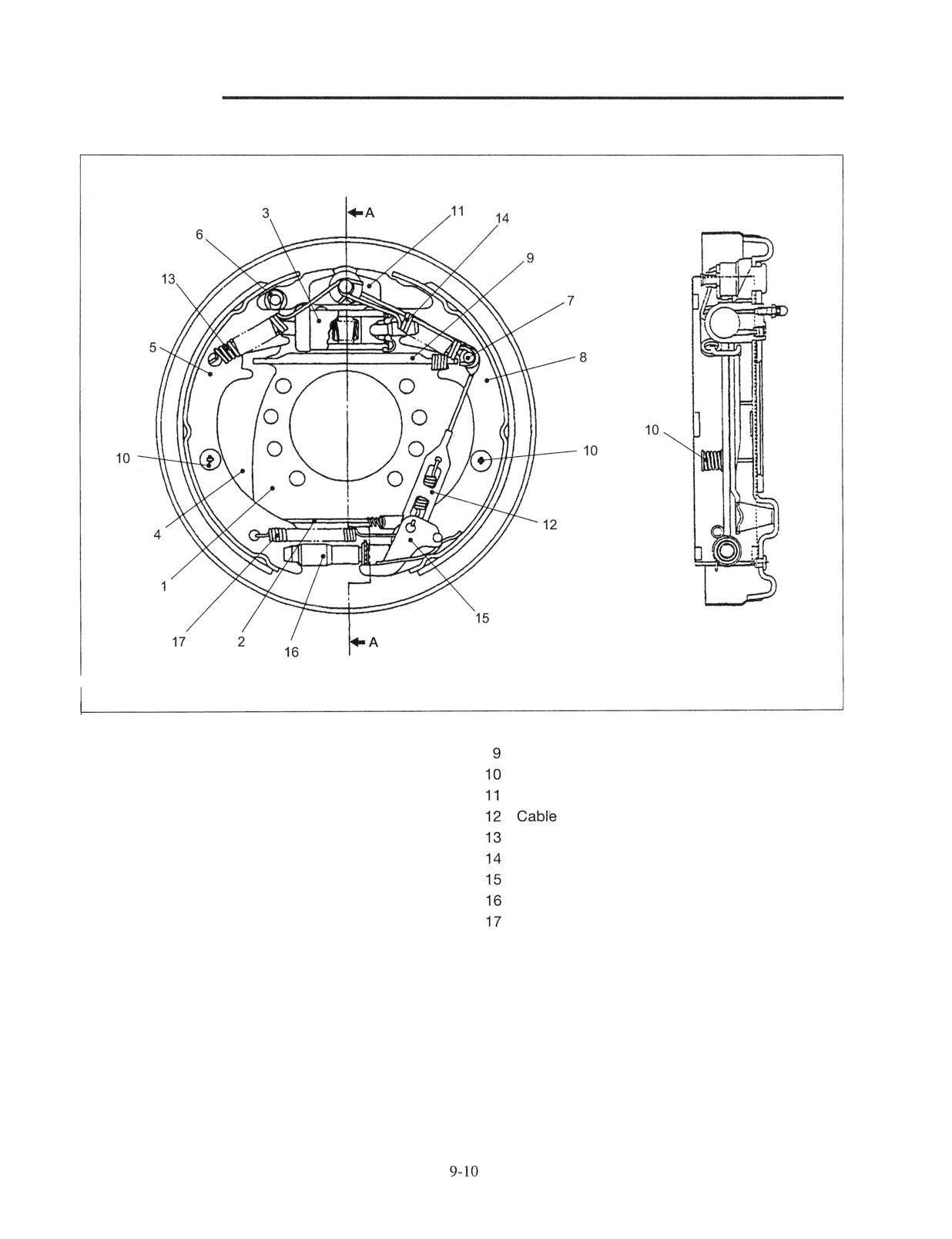
BRAKE SYSTEM
2, 3 ton classes
Section A - A
The illustration shows a left-hand wheel brake.
209784
Sequence
1 Backing plate assembly
Strut, Anti-rattling spring
2 Parking brake cable, Snap ring
Pin, Hold-down spring, Cup
3 Wheel cylinder
Shoe guide plate
Prepare Parts 4,5 and 6 in assembly beforehand.
with spring
4 Parking brake lever
Return spring (primary)
5 Primary shoe and lining assembly
Return spring (secondary)
6 Retainer, Washer
Adjusting lever, Adjusting spring
Prepare Parts 7 and 8 in assembly beforehand.
Adjusting screw
7 Pin, Sheave, Washer
Return spring
8 Secondary shoe and lining assembly
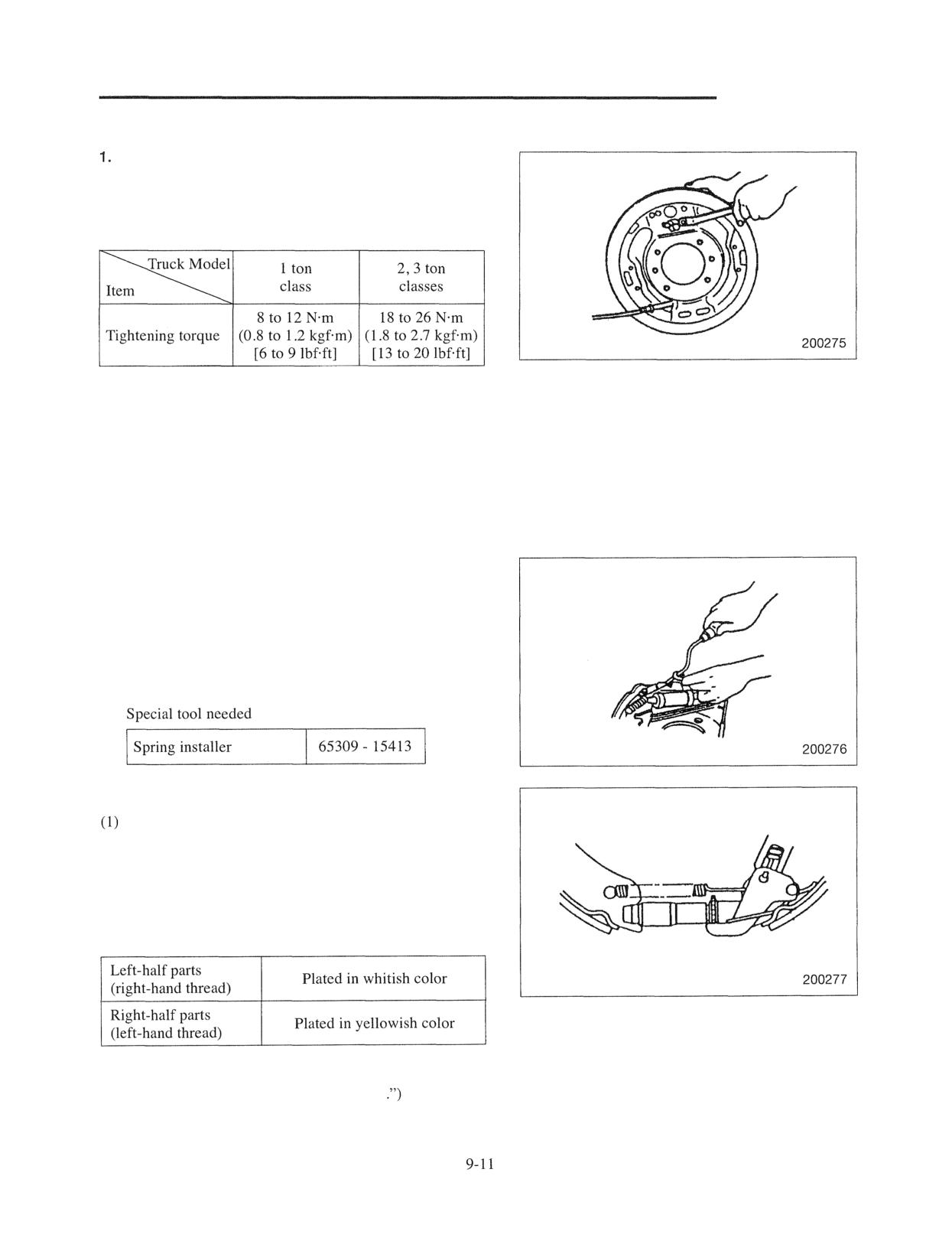
BRAKE SYSTEM
Suggestions for Reassembly
Wheel cylinder installation
Apply liquid packing to the mounting face of the wheel
cylinder before installing it. Tighten to the specified
torque.
2. Greasing
Apply a thin coat of the specified brake grease to the
following areas.
(1) Shoe ledges (6 locations)
The ledges are those portions of the backing plate in
contact with the shoe.
(2) Anchor pin surface in contact with the shoe ends
3. Shoe and lining installation
Ensure that each connector link of the wheel cylinder has
been correctly inserted into the shoe web.
4. Return spring installation
Use a special tool to install the return springs to the
backing plate pins.
5. Automatic adjuster installation
Clean the adjusting screw and associated parts. Apply
grease to the threaded portions and the screw socket.
Ensure that the screw turns easily when rotated by
hand.
If the screw is hard to turn, replace it with a new one.
(2) Identification of adjusting screws and levers
Note: After reassembly, bleed air out of the brake lines.
(Refer to "Inspection and Adjustment
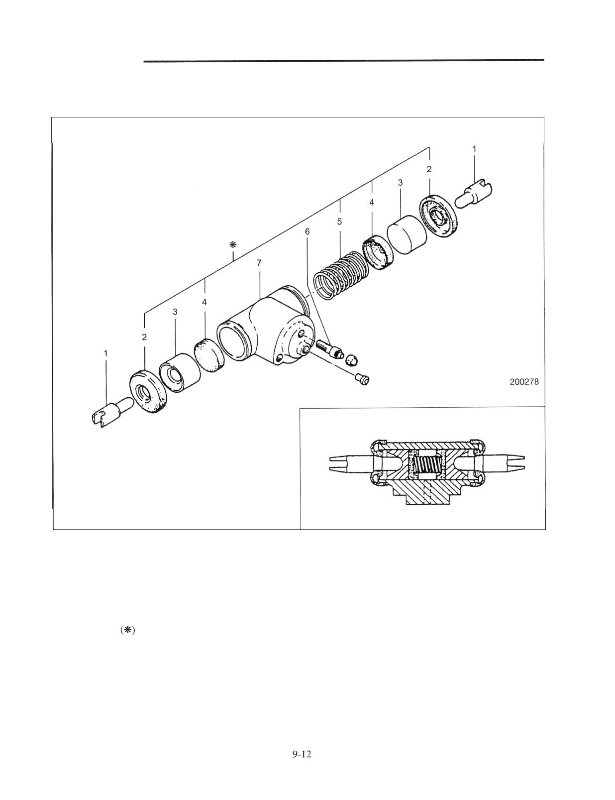
BRAKE SYSTEM
Wheel Cylinder
Disassembly
200279
Sequence
1 Connector link
5 Return spring
2 Boot
6 Bleeder screw, Cap
3 Piston
7 Cylinder body
4 Piston cup
Note: The part
to be changed periodically are included
in the Brake Repair Kit.
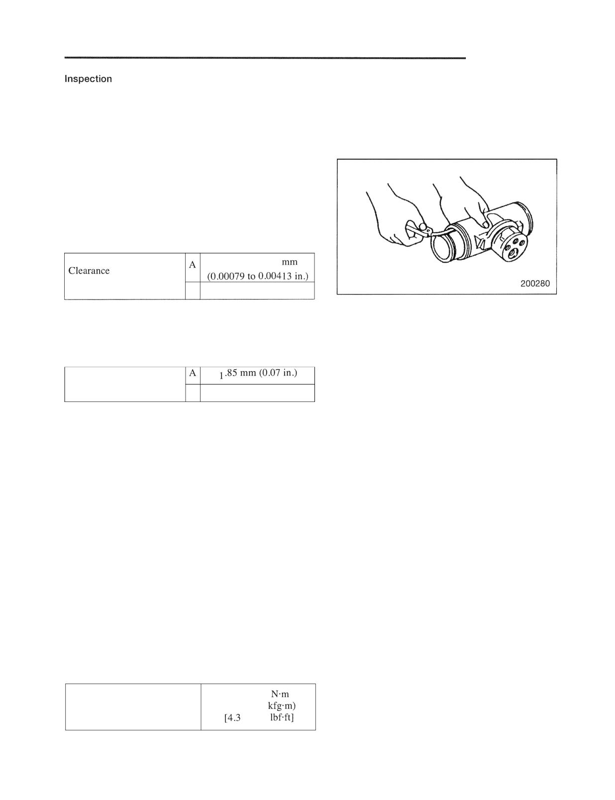
BRAKE SYSTEM
and Repair
(1) Cylinder body
(a) Check the bore for rusting, erosion or scoring.
(b) Check the threads of bleeder screw and oil pipe for
damage.
(2) Pistons
(a) Check the sliding surface for rusting or scratching.
(b) With the piston installed in the cylinder body,
measure the piston-to-cylinder clearance. Replace
if the clearance is in excess of the service limit.
A: Standard value
B: Service limit
0.020 to 0.105
between piston
and cylinder
B
0.15 rnm (0.0059 in.)
(3) Piston cups
Check for swelling, damage or other defects. Replace the
cup if defective even slightly.
A: Standard value
B: Service limit
Tightness between piston
cup and cylinder body
B
0.65 rnm (0.025 in.)
(4) Boots
Replace the boots if they show damage or aged
deterioration. In any event, the boots must be replaced
every year.
Reassembly
To reassemble, follow the disassembly procedure in
reverse, paying attention to the following points.
(1) Wash all metal parts clean with volatile cleaning
solvent, and completely dry them with compressed air.
(2) Apply a thin coat of rubber grease exclusively designed
for brake components or brake fluid to the cylinder
bore and piston cups.
(3) Be careful not to damage the lips of the cups.
(4) Make sure that the cups face the correct directions
when reassembled.
(5) Tighten the bleeder screw to the specified torque.
5.9 to 8.8
Tightening torque
(0.6 to 0.9
to 6.5
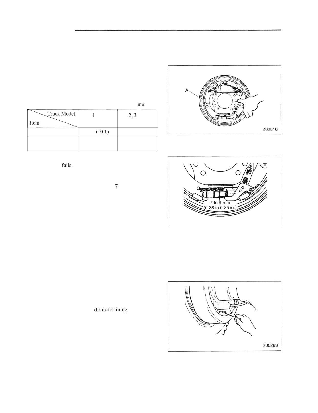
BRAKE SYSTEM
inspection and Adjustment
Automatic Adjuster Test
(I) With clearance A between the lining and drum, set
approximate to specification, pull the cable with
attached spring using a finger as shown. The lever
should turn the adjusting screw wheel by one notch
and, when the cable is released, return to the original
position.
Unit:
(in.)
ton
ton
class
classes
Drum inside diameter
254
310 (12.2)
Drum-to-lining
0.5 to 0.5
0.1 to 0.35
clearance A
(0.010 to 0.020)
(0.004 to 0.014)
(2) If the lever
or is slow to turn the adjusting screw
wheel, check the position of the lever relative to the
toothed wheel. The lever's actuating tip should touch
the toothed wheel at approximately to 9 mm (0.28 to
0.35 in.) below the centerline of the screw. If the lever
contact is out of the range, the lever will not correctly
engage with the toothed wheel, therefore failing or
slow to turn the wheel.
200282
(3) If the automatic adjuster fails to operate correctly, take
the following actions.
(a) Ensure that the adjusting spring is correctly hooked
to the primary shoe.
(b) Replace the fitting cable.
(c) Replace the lever.
(d) Replace the adjusting screw
Manual Adjustment
Using a screwdriver through the slotted hole on the back of
the backing plate, adjust the
clearance to
specification by rotating the adjusting screw wheel.
Note: Turning the wheel by one tooth corresponds to a
change of 0.03 mm (0.001 in.) in shoe diameter.
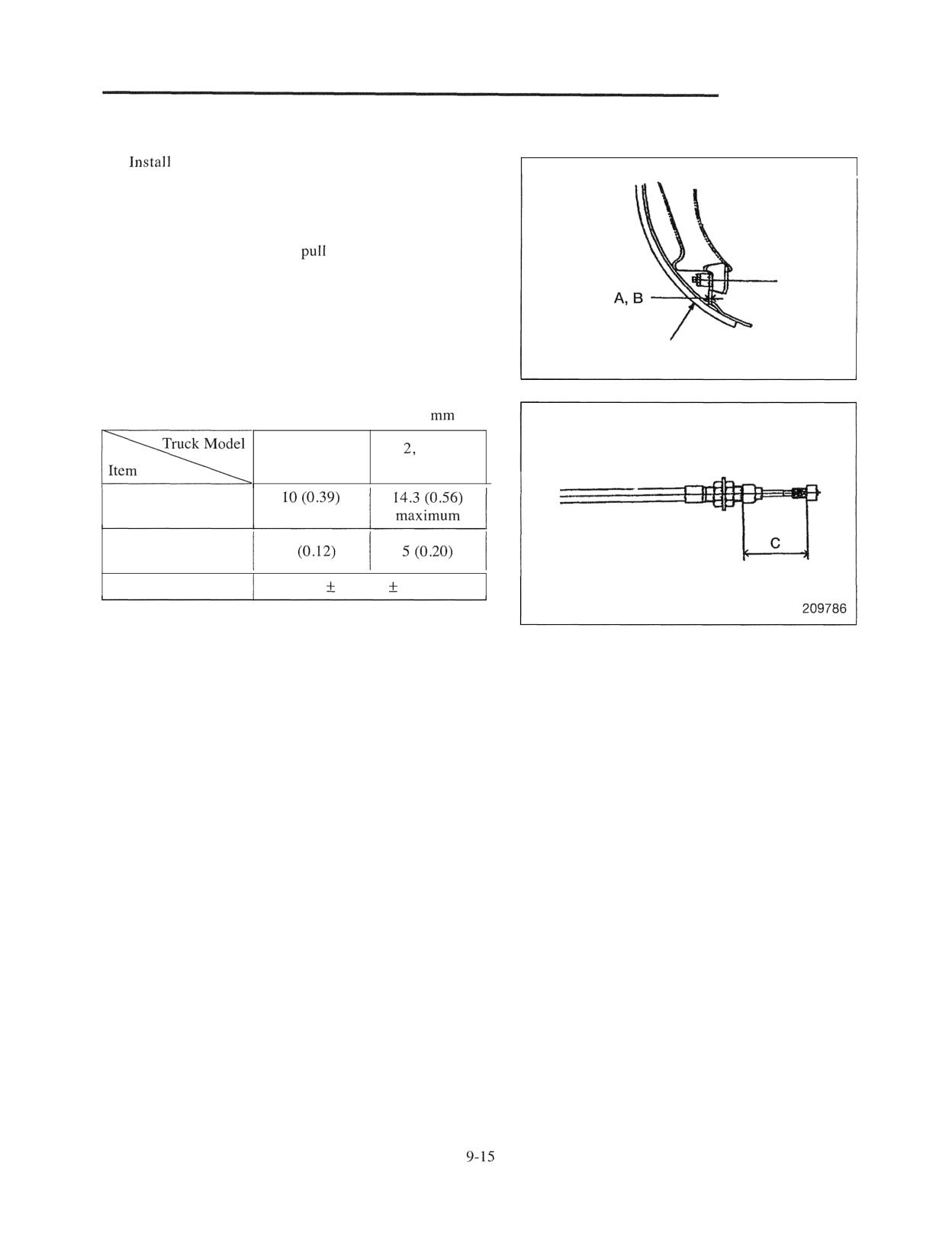
BRAKE SYSTEM
Parking Brake Cable Adjustment
(1)
the parking brake cable to the parking brake
lever as shown. Set the lever "free" (the lever resting
on the inner surface of the shoe, as indicated by the
chain double-dashed line).
(2) With the lever set "free,"
the cable until the shoe
just starts to work on the drum. The amount of cable
pulled A should meet the specification listed below.
(3) Move the parking brake lever by the amount specified
below. This is the neutral position. In the neutral
Shoe
position, the inner cable length C should be as
209785
specified below.
Unit:
(in.)
1 ton
3 ton
class
classes
Cable pull A before
shoe works on drum
maximum
Distance B to reach
3
neutral
Inner cable length C
44
4 (1.73
0.16)
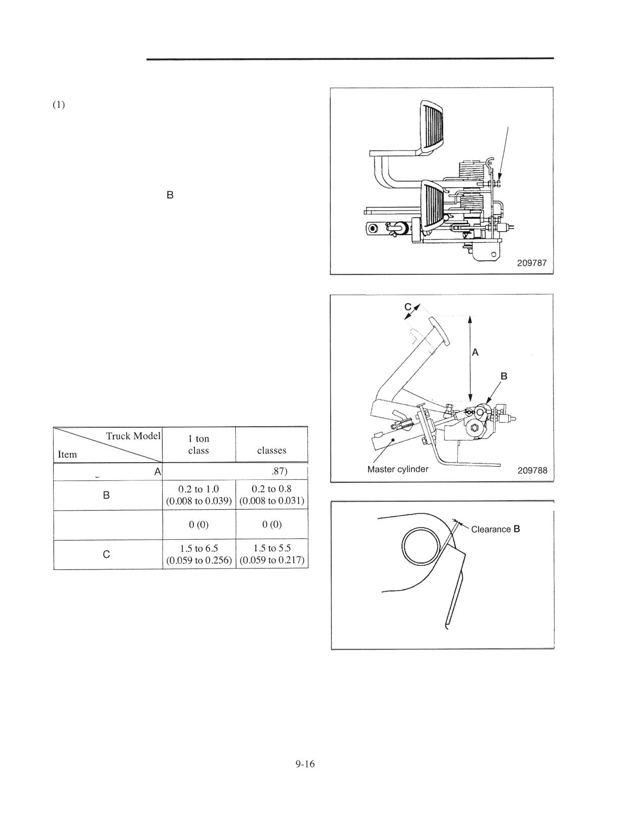
BRAKE SYSTEM
Brake Pedal Adjustment
Using the stop bolt, adjust the installed height A of the
brake pedal (from the floor to the top of the pad). After
Stop bolt
adjustment, lock the stop bolt.
(2) Adjust the push rod length of the master cylinder
Truck with powershift transmission
With the push rod-to-piston clearance removed,
adjust the clearance to specification by turning the
push rod. After adjustment, lock the clevis with the
nut.
(3) Ensure that the pedal play is to specification.
Note: (a) Ensure that the clevis pin between the brake
pedal and push rod is firmly in place as
illustrated.
(b) Ensure that the snap pin is firmly engaged.
(c) Ensure that the brake pedal operates smoothly
without obstruction or other problems.
Unit: mm (in.)
2,3 ton
Pedal height from floor
182 to 200 (7.16 to 7
Clearance
Push rod-to-piston
clearance
Pedal play
Detail B
209789
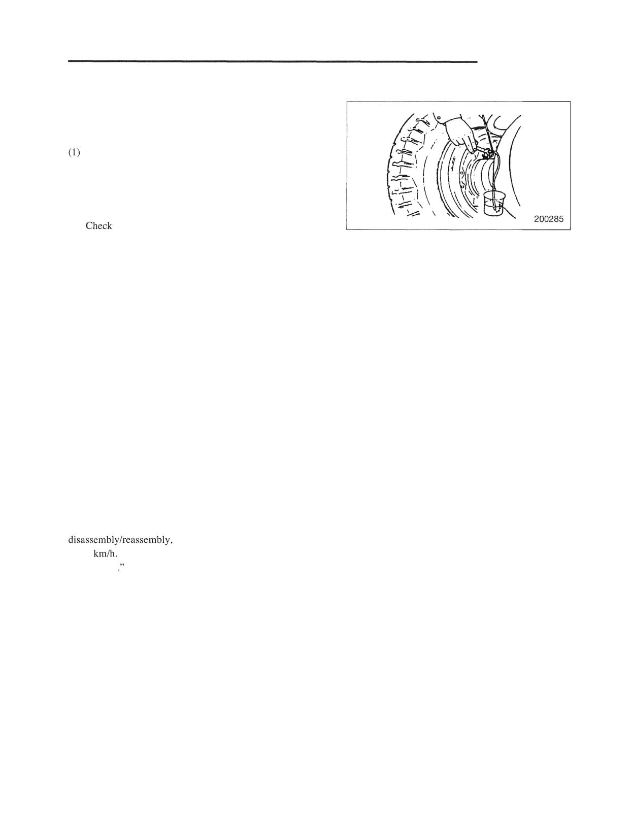
BRAKE SYSTEM
Bleeding Brake Lines
After any portion of the brake fluid lines has been
disassembled for repair or service, or if the brake pedal
feels spongy, bleed the brake lines as follows:
Install one end of a transparent vinyl tube onto the
bleeder screw of the right-hand wheel cylinder, which
is located farther from the master cylinder than the left-
hand wheel cylinder. Put the loose end of the tube into
a container filled with brake fluid.
(2)
the brake fluid level in the reservoir tank. Fill
up as necessary.
(3) After cycling the pedal several times, depress the pedal
and keep it depressed. With the pedal depressed,
loosen the bleeder screw. While the brake fluid is
flowing through the tube, tighten the bleeder screw.
(4) Repeat Step (3) until the fluid flowing through the tube
is free of air bubbles. Repeat the same procedures for
the left-hand wheel cylinder. With the brake lines free
of air, fill brake fluid into the reservoir tank to the
specified level.
Note: (a) Take care to maintain the brake fluid in the
reservoir tank at sufficient levels while the
bleeding operation is in progress.
(b) Use only the brake fluid of specified brand and
grade. Avoid mixing different types of fluids.
Braking Performance Test
With all of the required adjustments completed after
check the braking force at a speed
of 10
Readjust as necessary by referring to "Manual
Adjustment
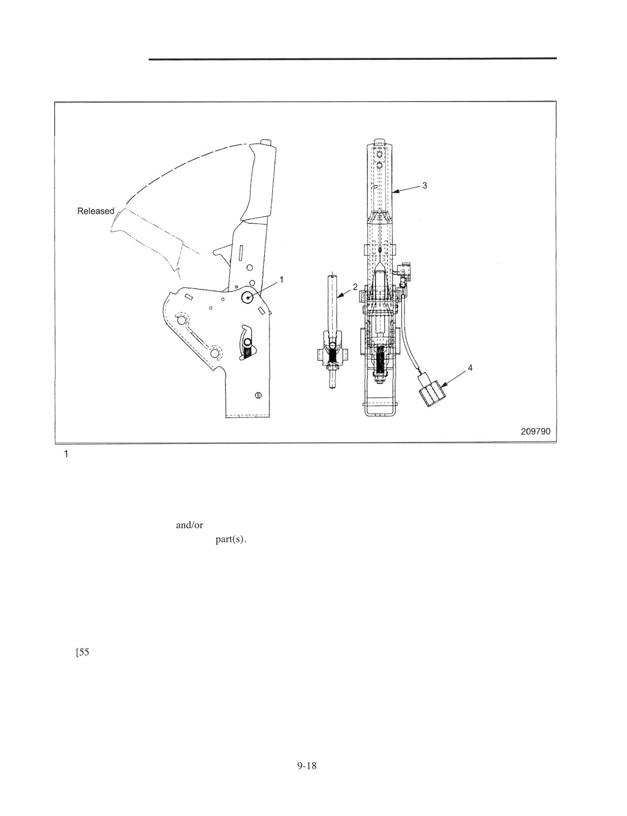
BRAKE SYSTEM
Parking Brake Lever
Applied
Lever support pin
3 Parking brake lever assembly
2 Adjusting screw
4 Parking brake switch
Inspection and Repair
(1) If the lever support pin
the pin hole in the lever
are badly worn, replace the worn
(2) Replace the parking brake cable if it is stretched,
damaged or rusted.
Reassembly
With the parking brake cable and lever connected, the force
required to pull the lever should be 245 to 295 N (25 to 30
kfg)
to 66 lbf].
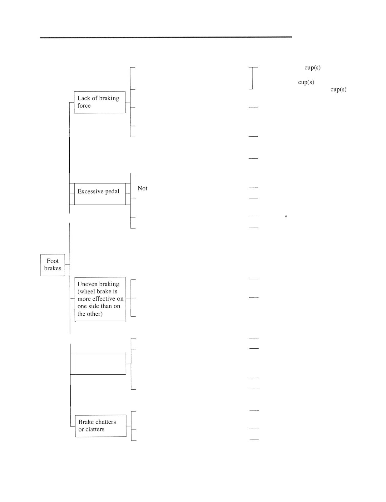
BRAKE SYSTEM
Troubleshooting
Oil leaking past primary cup in master
*Replace piston
if cylinder
cylinder
is free from unacceptable wear.
Replace the
and fluid
Oil leaking past cups in wheel cylinder
with genuine parts if the
is distorted.
Oil leaking from oil pipe connection
Retighten, or replace pipe and
connector.
Shoe lining worn
--- Replace.
Shoe lining dirty with oil or grease
Clean or replace.
Air trapped in brake fluid lines
Bleed air at master and
wheel cylinders.
r
Piston cup defective in master cylinder
-
Replace.
-
enough fluid in reservoir tank
Refill.
stroke
Push rod to piston clearance too large in
Readjust.
master cylinder
Brake fluid leakage
Refer to above.
I
Automatic adjuster inoperative
Ensure that cable guide and
adjusting spring are correctly
installed. If still inoperative,
replace cable with spring, lever,
and adjusting screw.
brakes
Lining or drum dirty with oil or grease
Clean with gasoline. If lining
in less effective brake
still dirty, replace.
Wobbly or loose-mounted drum in less
Replace drum. If loose, readjust
effective brake
and retighten.
Wheel tires inflated unequally
-
Reinflate to specification
Lining glazed
Sand.
I
Worn lining
Replace shoe and lining
assemblies.
-
Brake squeals
- Backing plate securing bolts loose
-
Retighten.
-
Wheel bearings loose
Readjust preload and retighten.
Brake drum dirty
Clean with cleaning solvent.
Anchored ends of shoes rattling
Repair or replace.
on anchor
Shoe ledges badly worn
Replace backing plate.
Pistons badly worn in wheel cylinder
Replace wheel cylinder.
BRAKE SYSTEM
- Readjust.
Will squeal
Lining to drum clearance too small
- Readjust.
Brake drum badly distorted
Repair or replace.
brake
Parking brake cable longer than
- Check lining to drum clearance.
specification
If brake will still not apply,
readjust cable length.
lining worn to the service limit
- Replace shoe and lining
Will not apply
assemblies.
Lining to drum clearance too large
- Readjust.
Lever lacks operating force
- Readjust to specification.
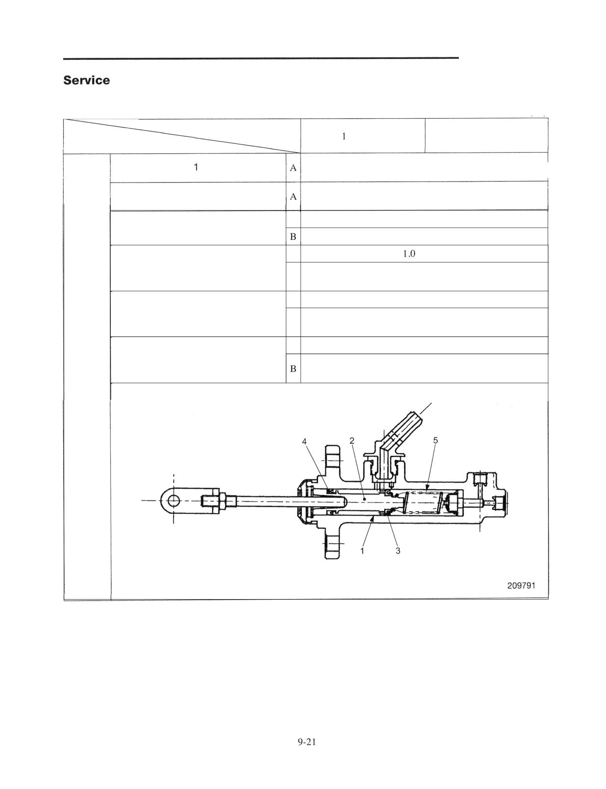
BRAKE SYSTEM
Data
A: Standard value
B: Service limit
Unit: mm (in.)
Truck Models
ton class
2, 3 ton classes
Items
Cylinder bore size
19.05
(0.7500)
I
Diameter of piston 2
19.05
(0.7500)
A
0.020 to 0.105 (0.00079 to 0.00413)
Clearance between cylinder and piston
0.15
(0.0059)
A
(0.039)
Primary cup tightness 3
0.4
(0.016)
B
(Replace every year or whenever overhauling)
A
1.1
(0.043)
Secondary cup tightness 4
0.4
(0.016)
B
(Replace every year or whenever overhauling)
A
59.2
(2.3)
Free length of return spring 5
53.9
(2.1)
Master
(Replace every year or whenever overhauling)
cylinder
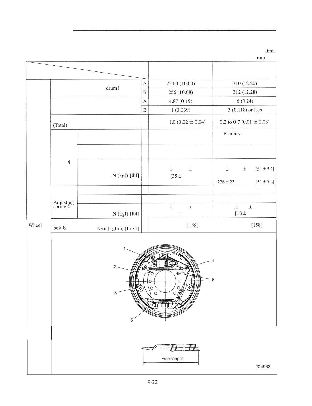
BRAKE SYSTEM
A: Standard value
B: Service
Unit:
(in.)
Truck Models
1 ton class
2,3ton classes
Items
Inside diameter of brake
Thickness of lining 2
Clearance between drum and lining 3
A
0.5 to
120 (4.72)
Free length
A
102 (4.02)
Secondary: 139.3 (5.48)
Primary: 134 (5.3)
Length under set force
A
111 (4.4)
Secondary: 145.5 (5.8)
Return
spring
Primary:
Set force
A
157
16 (16
1.6)
226
23 (23
2.3)
1
3.61
Secondary:
(23f 2.3)
Free length
A
79 (3.11)
104.5
(4.11)
I
122 (4.8)
Length under set force
A
98.5
(3.9)
Set force
137
14 (14
1.4)
78
8 (8
0.8)
A
[31
3.11
1.81
Tightening torque for backing plate
A
215 (21.9)
215 (21.9)
brakes
4 secondary spirng