Cat Lift Trucks. For use with K21/K25 and S4S Engine Service Manuals (2007) - page 1
Chassis Mast
For use with
and S4S Engine Service Manuals.
FOREWORD
This service manual is a guide for servicing
Lift Trucks. For your convenience the
instructions are grouped by systems as a ready reference.
Long productive life of your
depends on regular and proper servicing. Servicing
consistent with what you will learn by reading this service manual. Read the respective sections
of this manual carefully and familiarize yourself with all of the components before attempting
to start a test, repair or rebuild job.
The descriptions, illustrations and specifications contained in this manual are
trucks with
serial numbers in effect at the time of printing. Cat Lift Trucks reserves the right to change
specifications or design without notice and without incurring obligation.
The trucks listed in this manual are powered by
gasoline engines or
diesel
engines. For the engine servicing, please refer to the applicable engine service manual.
Safety Related Signs
The following safety related signs are used in this service
manual to emphasize important and critical instructions:
result in death or serious injury.
Indicate a potentially hazardous
situation which, if not avoided, may
result in minor or moderate injury, or
to your machine.
Indicates a condition that can cause
(NOTE)
damage to, or shorten service life of,
the machine.
Pub. No. 99719-89120
rication and
maintenance for these lift trucks,
read and understood the instructions in the
recommended by Cat Lift Trucks, are outlined
OPERATION
MAINTENANCE MANUAL.
in the
MANUAL.
truck
is dangerous and
Improper performance of lubrication or
could result in injury or death.
maintenance procedures is dangerous and
4.
Lower the forks or other implements to the ground
could result in injury or death. Read and
before performing any work on the truck. If this
understand the OPERATION & MAINTENANCE
cannot be done, make sure the forks or other
MANUAL before performing any lubrication or
implements are blocked correctly to prevent them
maintenance on these trucks.
from dropping unexpectedly.
The serviceman or mechanic may be unfamiliar with
5.
Use steps and grab handles (if applicable) when
many of the systems on this truck. This makes it
mounting or dismounting a truck. Clean any mud
or debris from steps, walkways or work platforms
important to use caution when performing service
before using. Always face truck when using steps,
work. A knowledge of the system
components
is important before the removal or disassembly of any
ladders and walkways. When it is not possible to
component.
use the designed access system, provide ladders,
scaffolds, or work platforms to perform safe repair
Because of the size of some of the truck components,
operations.
the serviceman or mechanic should check the weights
noted in this Manual. Use proper lifting procedures
6.
To avoid back injury, use a hoist when lifting
when removing any components.
components which weigh 23 kg (50 lb.) or more.
Make sure all chains, hooks, slings, etc., are in
Following is a list of basic precautions that should
good condition and are of the correct capacity. Be
always be observed.
sure hooks are positioned correctly. Lifting eyes
Read and understand all warning plates and decals
are not to be side loaded during a lifting operation.
on the truck before operating, lubricating or
7.
To avoid burns, be alert for hot parts on trucks
repairing the product.
which have just been stopped and hot fluids in
2. Always wear protective glasses and protective
lines, tubes and compartments.
shoes when working around trucks. In particular,
8.
Be careful when removing cover plates. Gradually
wear protective glasses when pounding on any part
back off the last two bolts or nuts located at
of the truck or its attachments with a hammer or
opposite ends of the cover or device and pry cover
sledge. Use welders gloves,
apron
loose to relieve any spring or
pressure, before
and other protective clothing appropriate to the
removing the last two bolts or nuts completely.
welding job being performed. Do not wear
9.
Be careful when
filler caps, breathers and
fitting or torn clothing. Remove all rings from
plugs on the truck. Hold a rag over the cap or plug
fingers when working on machinery.
to prevent being sprayed or splashed by liquids
3. Do not work on any truck that is supported only by
under pressure. The danger is even greater if the
lift jacks or a hoist. Always use blocks or jack
truck has just been stopped because fluids can be
stands to support the truck before performing any
hot.
disassembly.

10. Always use tools that are in good condition and be
19. Tighten connections to the correct torque. Make
sure you understand how to use them before
sure that all heat shields, clamps and guards are
performing any service work.
installed correctly to avoid excessive heat,
vibration or rubbing against other parts during
11. Reinstall all fasteners with same part number. Do
operation. Shields that protect against oil spray
not use a lesser quality fastener if replacements are
onto hot exhaust components in event of a line,
necessary.
tube or seal failure, must be installed correctly.
12. If possible, make all repairs with the truck parked
20. Relieve
pressure in air, oil or water systems
on a level, hard surface. Block truck so it does not
before any lines, fittings or related items are
roll while working on or under truck.
disconnected or removed. Always make sure all
13. Disconnect battery and discharge any capacitors
raised components are blocked correctly and be
(electric trucks) before starting to work on truck.
alert for possible pressure when disconnecting any
Hang "Do not Operate" tag in the Operator's
device from a system that utilizes pressure.
Compartment.
21. Do not operate a truck if any rotating part is
14. Repairs, which require welding, should be
damaged or contacts any other part during
performed only with the benefit of the appropriate
operation. Any high speed rotating component that
reference information and by personnel adequately
has been damaged or altered should be checked for
trained and knowledgeable in welding procedures.
balance before reusing.
Determine type of metal being welded and select
correct welding procedure and electrodes, rods or
wire to provide a weld metal strength equivalent at
least to that of parent metal.
15. Do not damage wiring during removal operations.
Reinstall the wiring so it is not damaged nor will it
be damaged in operation by contacting sharp
corners, or by rubbing against
object or hot
surface. Place wiring away form oil pipe.
16. Be sure all protective devices including guards and
shields are properly installed and functioning
correctly before starting a repair. If a guard or
shield must be removed to perform the repair work,
use extra caution.
17. Always support the
and carriage to keep
carriage or attachments raised when maintenance
or repair work is performed, which requires the
mast in the raised position.
18. Loose or damaged fuel, lubricant and hydraulic
lines, tubes and hoses can cause fires. Do not bend
or strike high pressure lines or install ones which
have been bent or damaged. Inspect lines, tubes
and hoses carefully. Do not check for leaks with
your hands. Pin hole (very small) leaks can result
in a high velocity oil stream that will be invisible
close to the hose. This oil can penetrate the skin
and cause personal injury. Use cardboard or paper
to locate pin hole leaks.
MANUAL
(Removal,
Assembly and Disassembly)
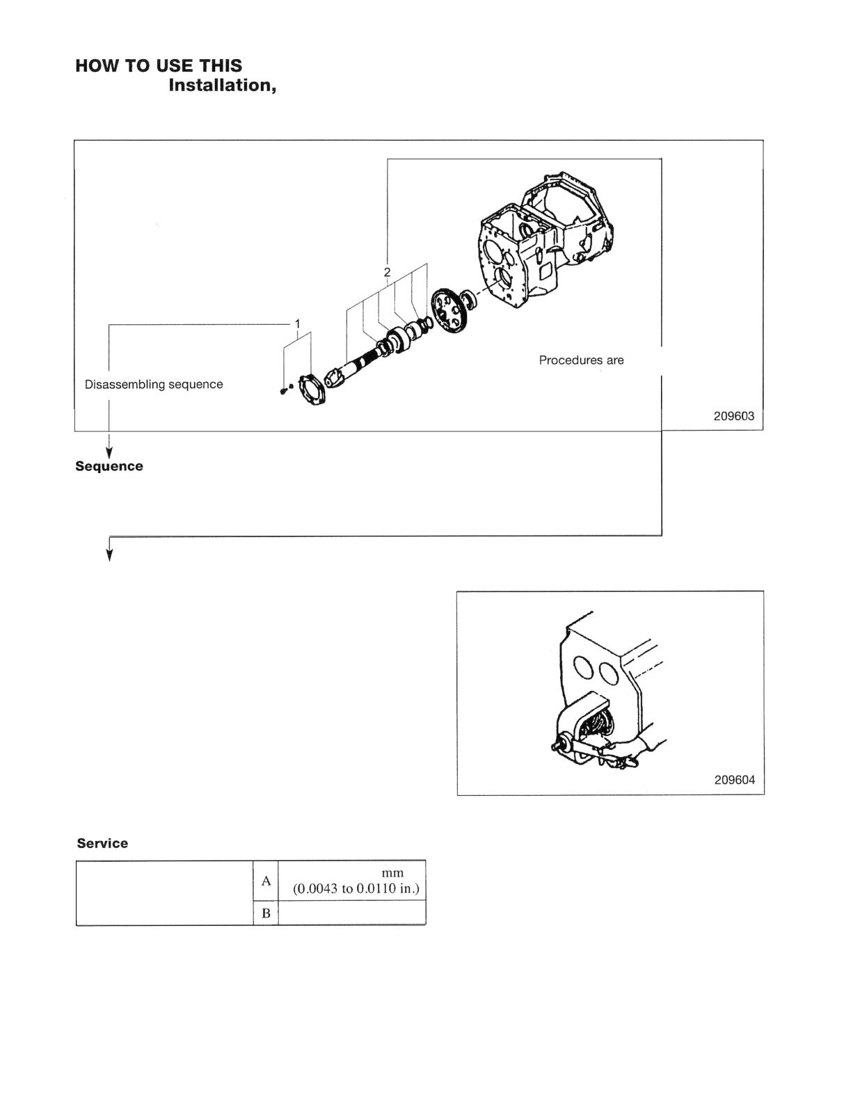
Disassembly diagram (example)
described in the text.
1 Cover, Bolt, Washer (part name)
2 Snap ring
(part name)
Suggestion for disassembling
1. Output shaft, Removing
Remove output shaft using a special tool.
Data
0.11 to 0.28
Gear Backlash
0.5 mm (0.020 in.)
A: Standard Value
B: Repair or Service Limit'
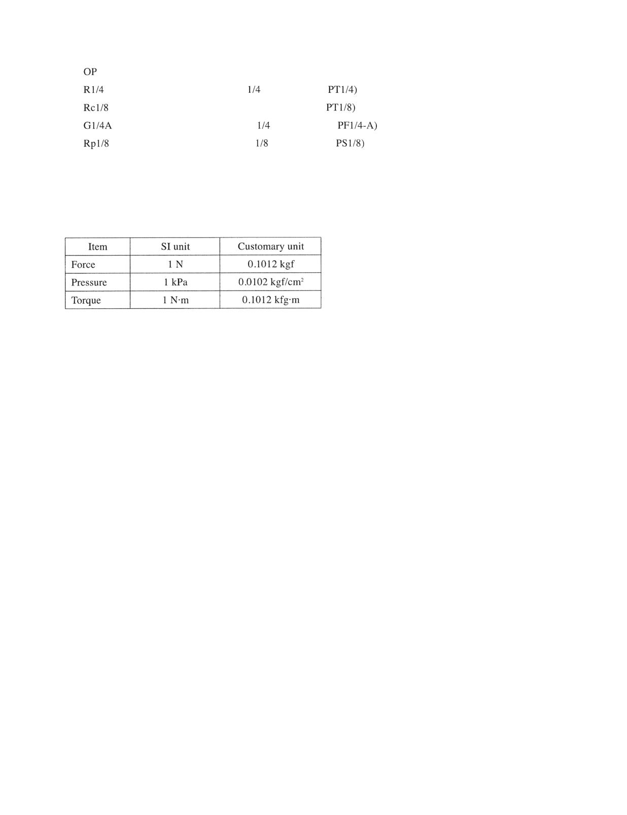
Symbols or abbreviation
Option
Taper pipe thread (external)
inch (formerly
Taper pipe thread (internal) 118 inch (formerly
Straight pipe thread (external)
inch (formerly
Straight pipe thread (internal)
inch (formerly
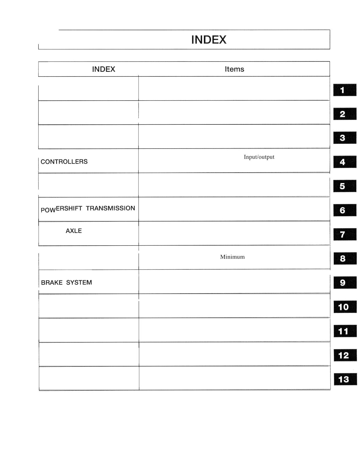
Units
1. SI Units are used in this manual.
2. The following table shows the conversion of SI unit and customary unit.
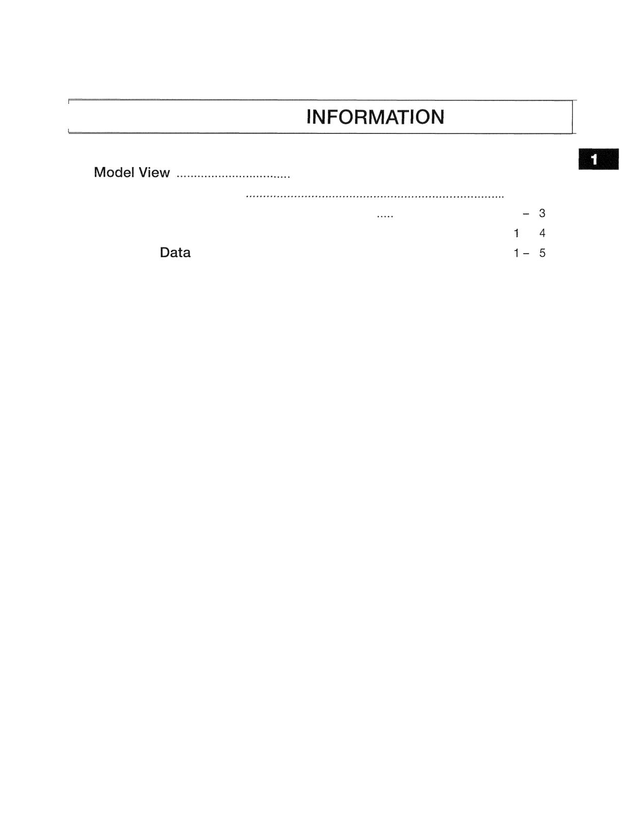
GROUP
GROUP
Model view, Truck models covered, Serial number locations,
GENERAL INFORMATION
Dimensions, Technical data
Fan removal and installation, Fan belt inspection and adjustment
COOLING SYSTEM
Console box, Chassis electrical devices, Battery maintenance, Electrical
ELECTRICAL SYSTEM
system schematic
Main functions, Service tool functions,
monitor, Error
codes and troubleshooting
POWER TRAIN
Removal and installation
Torque converter, 1 -speed transmission, Control valve,
Automatic 2-speed transmission
FRONT
AND
Front tires, Front axle, Reduction and differential
REDUCTION DIFFERENTIAL
Rear tires, Rear axle, Toe-in,
turning radius
REAR AXLE
Master cylinder, Wheel cylinders, Wheel brakes, Brake booster
Steering gear, Power cylinder, Flow divider
STEERING SYSTEM
Hydraulic tank, Gear pump, Control valve, Lift and tilt cylinders,
HYDRAULIC SYSTEM
Flow regulator valve, Down safety valve
Simplex mast, Duplex mast, Triplex mast
MAST AND FORKS
Maintenance standards, Periodic service chart, Periodic replacement
SERVICE DATA
parts, Lubrication instructions, Special tools
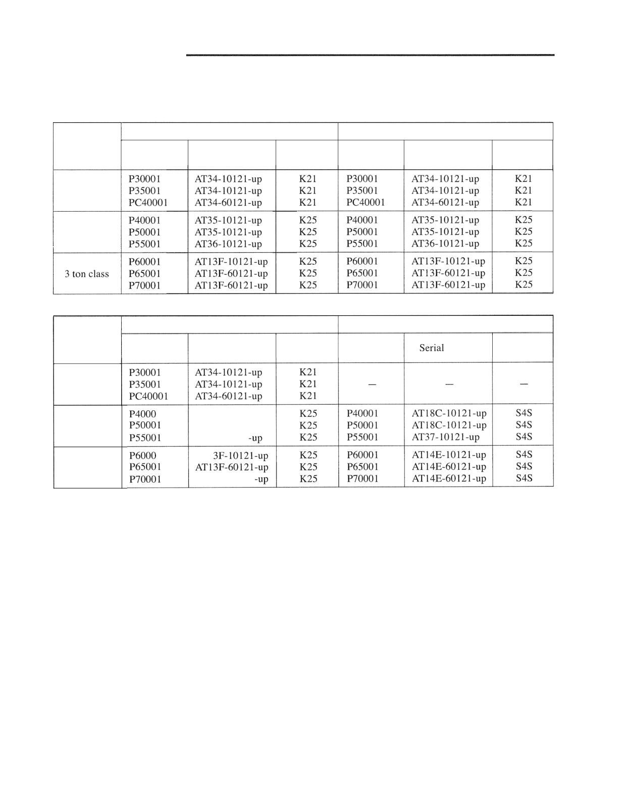
GENERAL
I
I
Truck Models Covered
I -
2
Serial Number Locations
I
Dimensions
-
Technical

GENERAL INFORMATION
Model View
GENERAL INFORMATION
Truck Models Covered
This Service Manual contains servicing and maintenance information for the following trucks:
Gasoline-engine models
Dual fuel gasoline-engine models
Truck class
Engine
Engine
Truck model
Serial number
Truck model
Serial number
mounted
mounted
1 ton class
2 ton class
3 ton class
LPG-engine models
Diesel-engine models
Truck class
Engine
Engine
Truck model
Serial number
Truck model
number
mounted
mounted
1 ton class
1
AT35-10121-UP
2 ton class
AT35-10121-up
AT36-10121
1
AT1
3 ton class
AT13F-60121
Note: Characters at the end of truck model should be read as follows:
C: Short body model
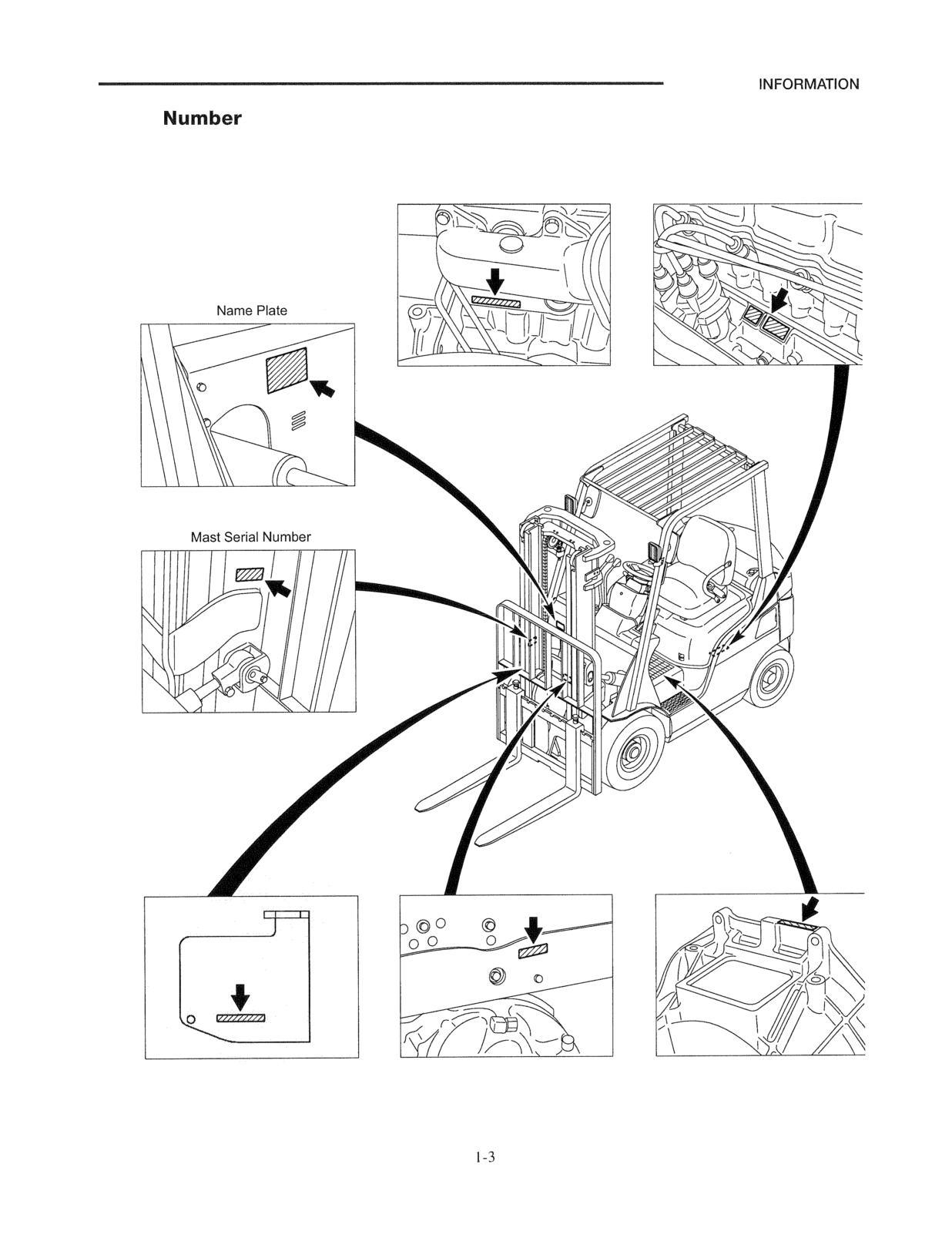
GENERAL
Serial
Locations
Diesel-engine Serial Number
Gasoline-engine Serial Number
Chassis Serial Number
Chassis Serial Number
Transmission Serial Number
21 0066
GENERAL INFORMATION
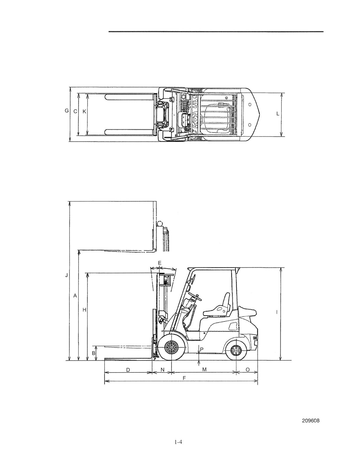
Dimensions
GENERAL
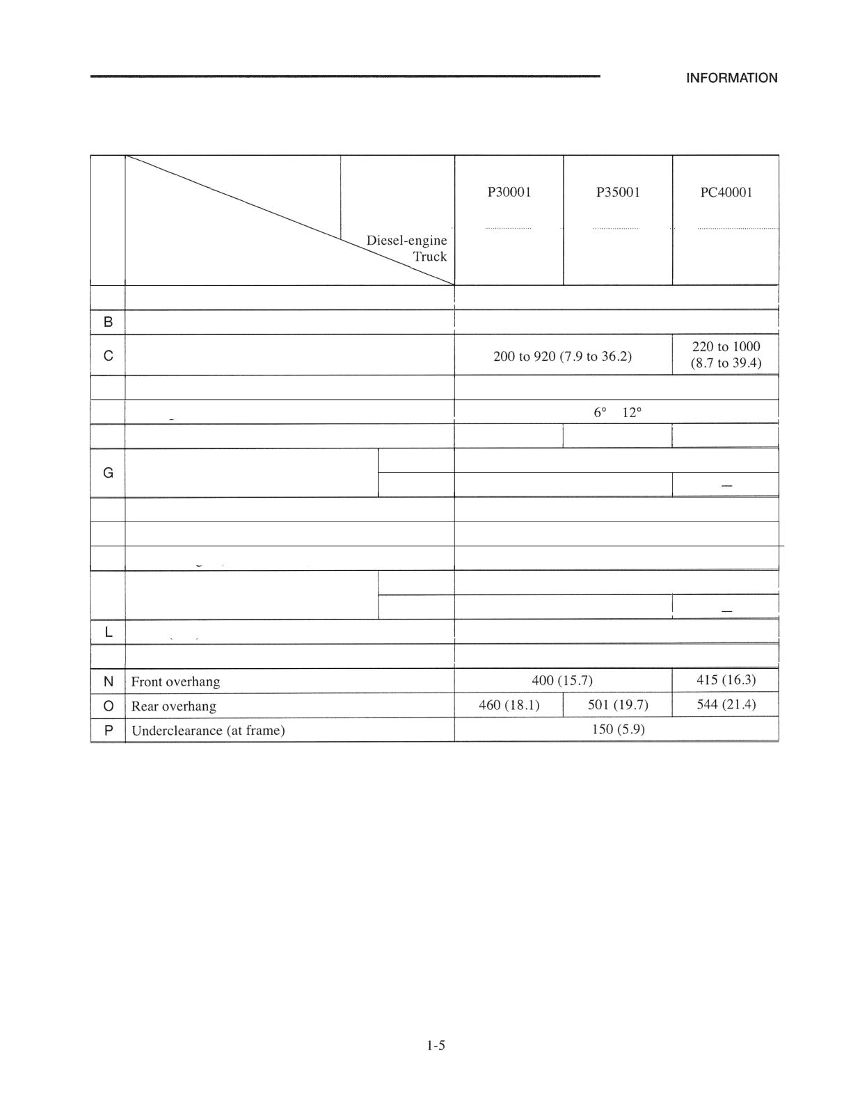
Technical Data
Unit: mm (in.)
Ref.
Model Gasoline-engine
No.
Truck
,
,
,.,,,,..,
,.,.
Item
A
Maximum lift
3000 (118)
Free lift
115 (4.5)
Fork spread (outside)
D
Fork length
920 (36.2)
E
Tilt angle (forward - backward)
-
F
Overall length
3180 (125.2)
3321 (126.8)
3279 (129.1)
Single tire
1065 (41.9)
Overall width (outside of tires)
Dual tire
1330 (52.4)
H
Overall height (to top of mast lowered)
1995 (78.5)
I
Overall height (to top of overhead guard)
2065 (81.3)
J
Overall height (mast extended)
4055 (159.6)
Single tire
890 (35)
K
Tread (front)
Dual tire
1025 (40.4)
Tread (rear)
900 (35.4)
M
Wheelbase
1400 (55.1)
GENERAL INFORMATION
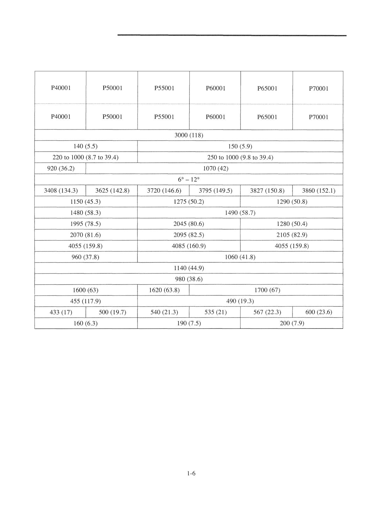
Unit: mm (in.)
NG SYSTEM
Specification
Structure
Removal and
Inspection and Adjustment
Fan Belt Inspection
2.
5
Fan Belt Tension
2
5
Connecting Radiator Hoses
2
5
Unit Layout
2
5
Coolant
2
6
Radiator
Cap
2
6
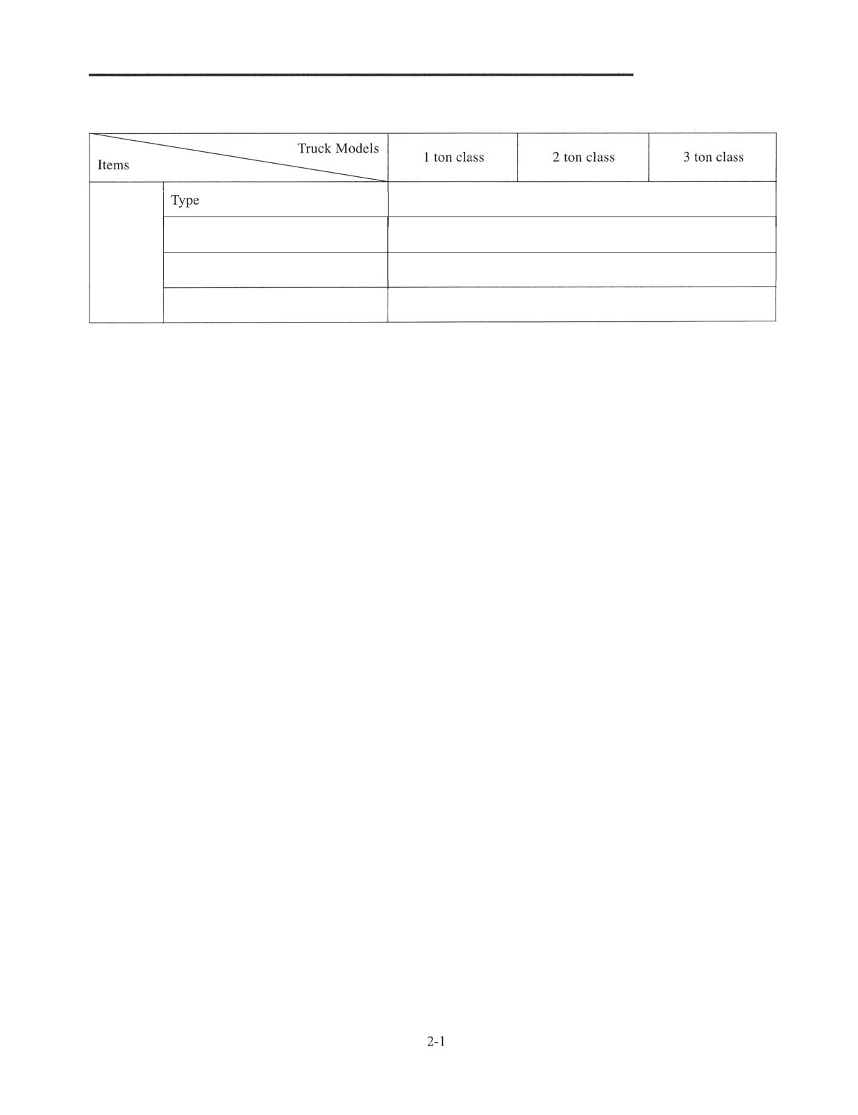
COOLING SYSTEM
Specification
Water-cooled, forced circulation
Radiator
Corrugated fin (pressure) type
Cooling
System
Water pump
Centrifugal type
Thermostat
Wax Pellet Type
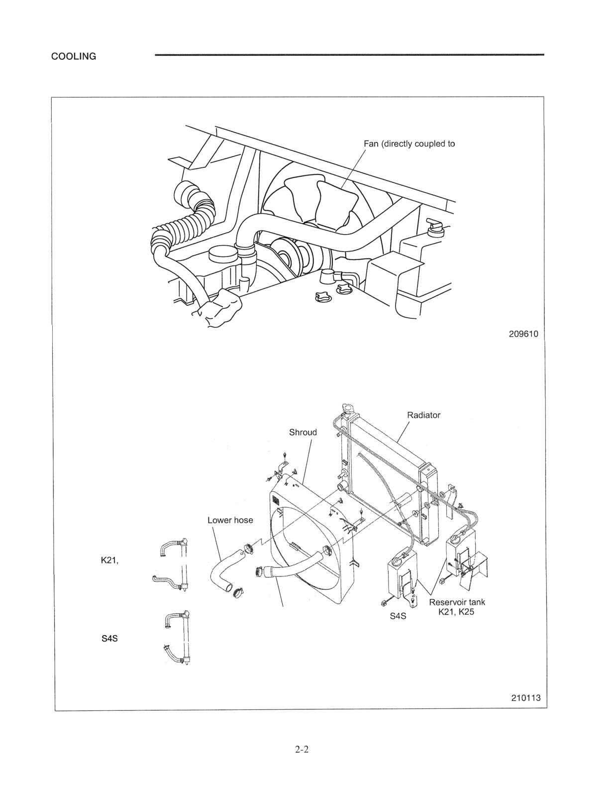
SYSTEM
Structure
engine)
Hose layout
K25
engines
\
Upper hose
engine
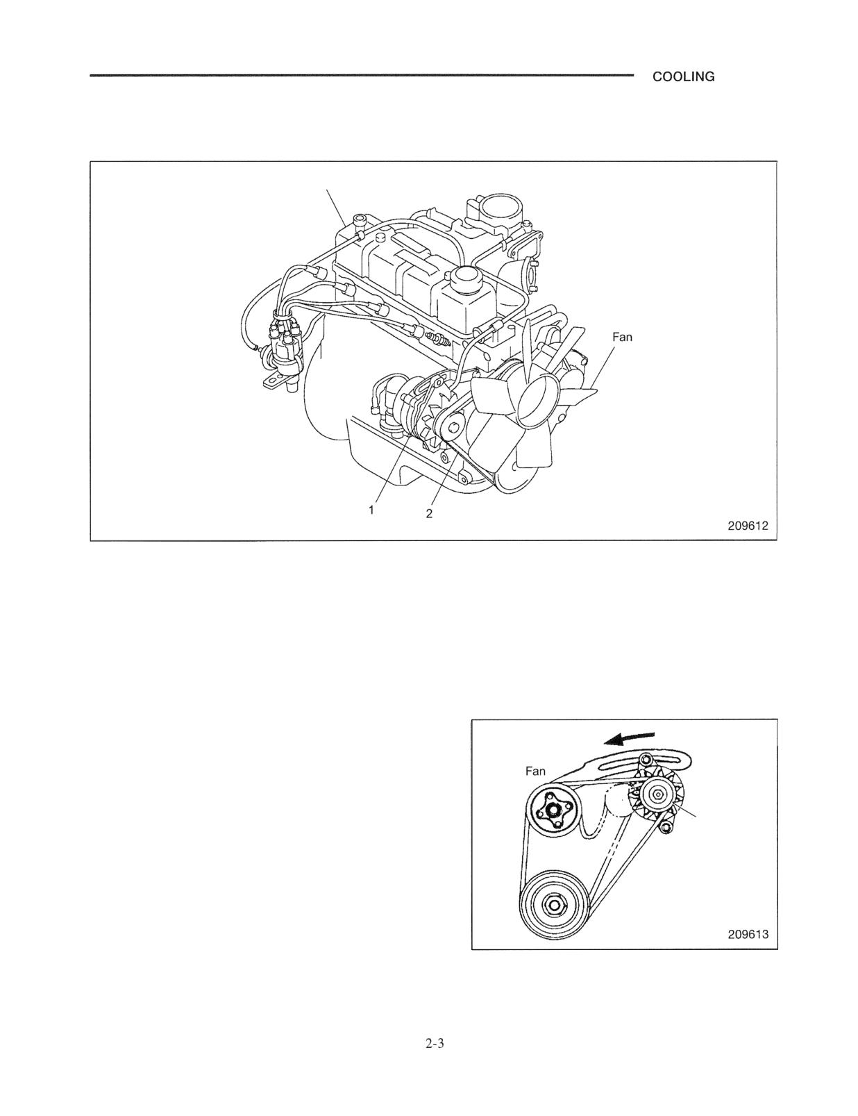
SYSTEM
Removal and Installation
Fan Belt Removal
Engine
Sequence
1 Tension pulley assembly, Bolt
2 Fan belt
Start by:
Remove the radiator cover.
Suggestions for Removal
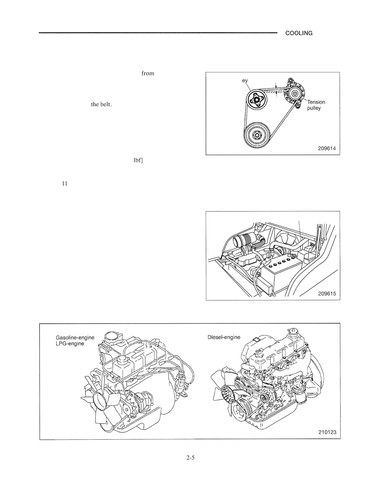
(I) Loosen the tension pulley lock bolt by three or four
turns. If the bolt is loosened insufficiently, the tension
pulley will not be moved.
Tension
Note: Do not loosen the lock bolt to such an extent that the
pulley
bolt would be removed.
(2) Move the tension pulley fully toward the fan, then
remove the belt.
COOLING SYSTEM
To install, follow the removal sequence in reverse. Also
follow the instructions given below.
(1) Before installing the belt, turn the fan to check for
smooth rotation. Replace the bearing if it generates
abnormal sound.
(2)
installing the
push it to make sure that the
tension pulley moves, then tighten the pulley lock bolt
firmly.
SYSTEM
Inspection and Adjustment
Fan Belt Inspection
(1) Check the belt for contamination
oil, grease or
dust. Replace the belt if required. When the
Fan pull
contamination is slight, clean the belt with a rag or
paper towel. Do not use gasoline, oil or any other
solvent to clean
(2) During the engine overhaul or belt tension adjustment,
check the condition of the belt. Replace the belt if it
has any damage.
Fan Belt Tension
Apply a force of 98 N (10 kgf) [22
perpendicularly to
the belt at a point midway between the fan pulley and
tension pulley. Adjust the tension until belt deflection is
between to 13 mm (0.43 to 0.51 in.).
Connecting Radiator Hoses
When connecting the hoses to the radiator, fit their ends
Hose
fully on the fittings and secure them with clamps. Make
sure that each hose is correctly connected and over the flare
of the fitting.
Unit Layout
COOLING SYSTEM
Coolant
Fill the radiator with coolant containing antifreeze. After
starting the engine and letting it warm up during operation,
check for abnormal noises. Check the coolant level in the
reserve tank to ensure it meets specifications.
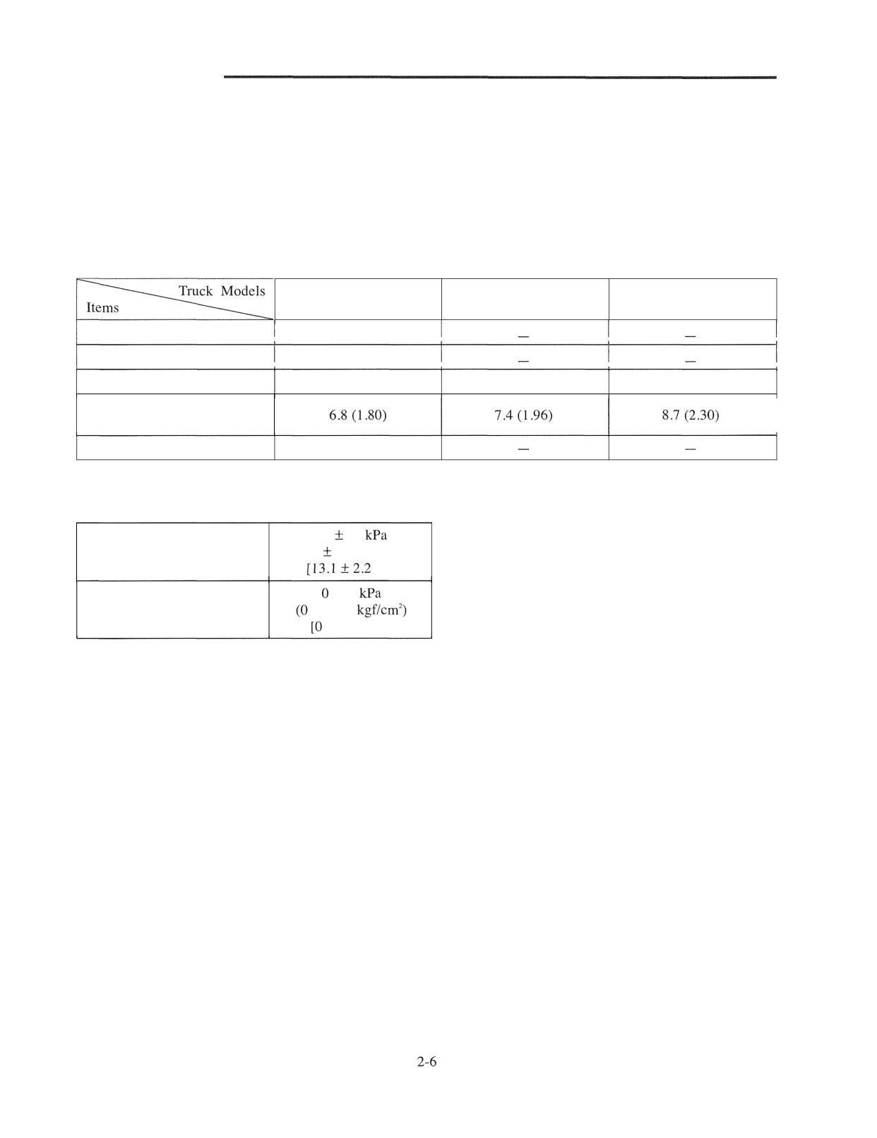
Quantity of coolant
Unit: liter (U.S. gal.)
1 ton class
2 ton class
3 ton class
Engine
3.95
(1.04)
Radiator
2.2
(0.58)
Reserve tank (FULL level)
0.65
(0.17)
0.65
(0.17)
0.65
(0.17)
Total quantity of coolant
(including coolant in hoses)
Oil cooler
0.094
(0.02)
Radiator Cap
-
-
90
15
Opening pressure
(0.92
0.15 kgf/crn2)
psi]
to 5
Vacuum valve
to 0.05
to 0.73 psi]
SYSTEM
Chassis Electrical Devices Wiring Outline
Structure
3 -
Console box
3 -
3
Major Electrical Components
3 -
5
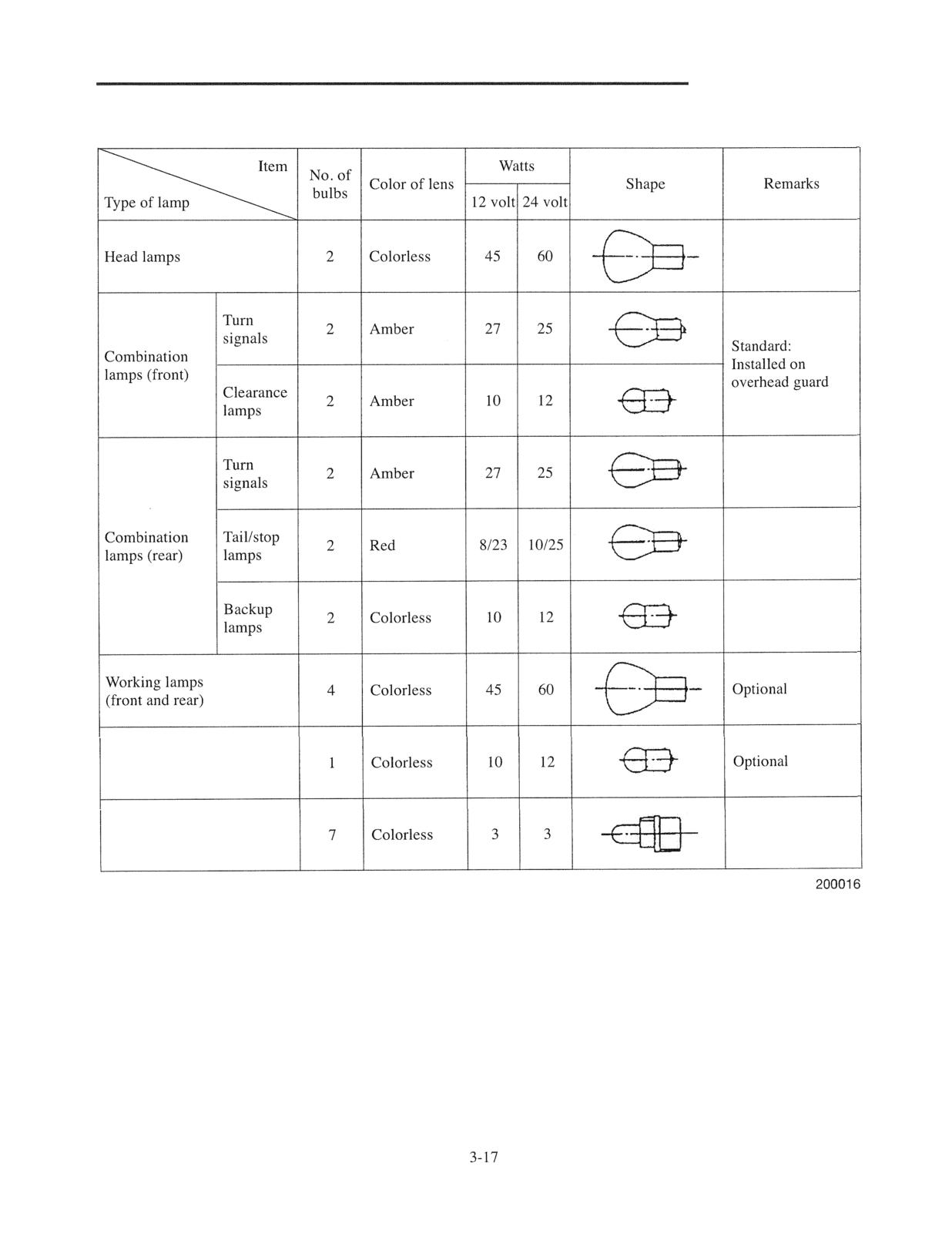
Lamp Bulb Specifications
3 - 17
Console Box
- 18
Disassembly
3 - 18
Instrument Panel
3 - 19
Battery Maintenance
Wire Color
Troubleshooting
3- 22
Electrical Schematic Diagram
- 25
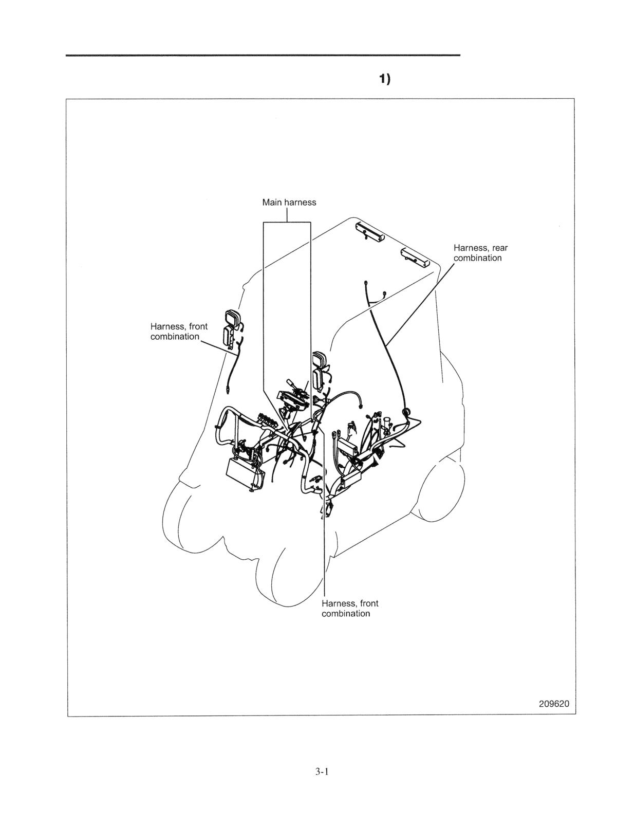
ELECTRICAL SYSTEM
Chassis Electrical Devices Wiring Outline (No.
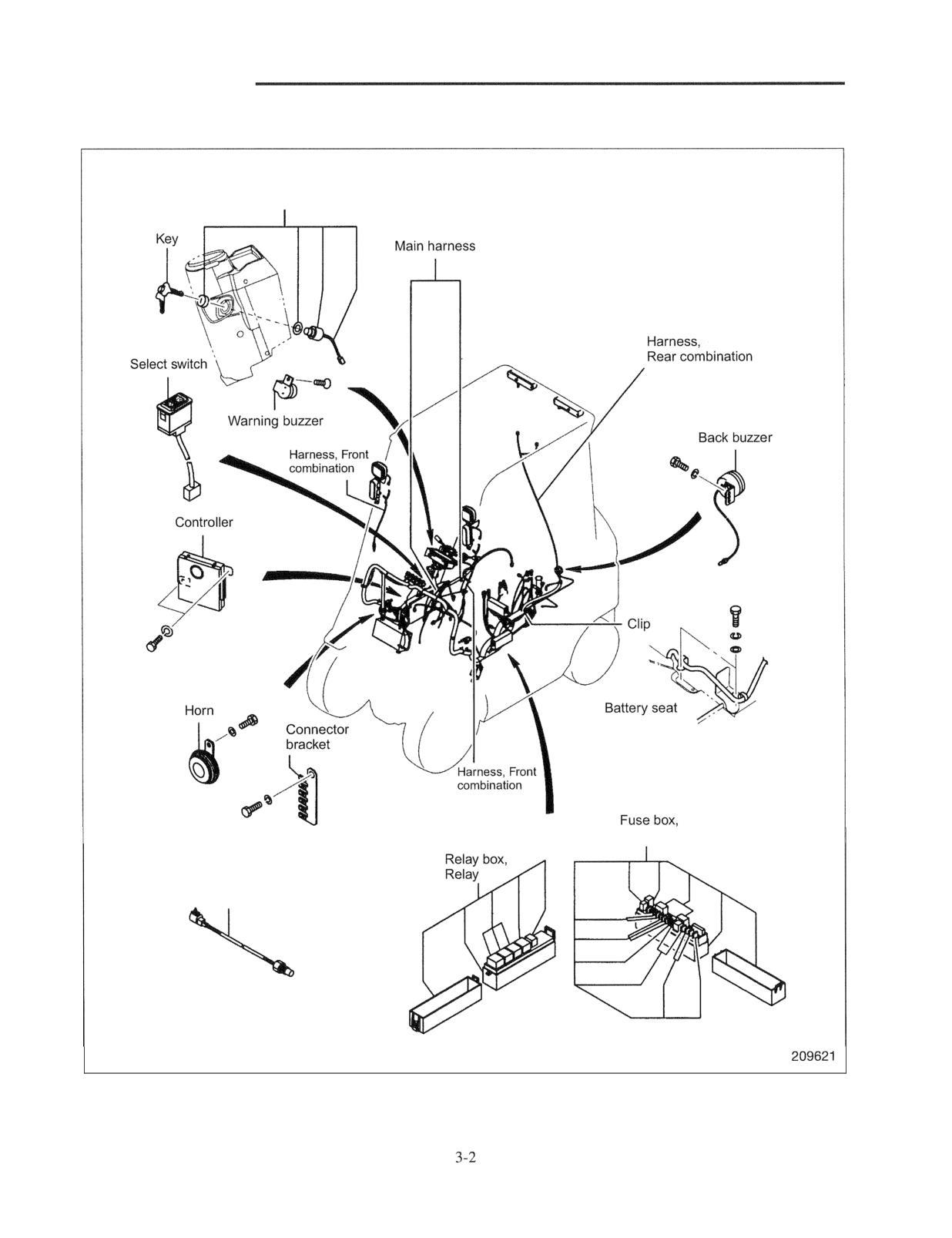
ELECTRICAL SYSTEM
Chassis Electrical Devices Wiring Outline (No. 2)
Starter switch
Fuse
Vehicle speed sensor
(Pulse generator)
Transmission
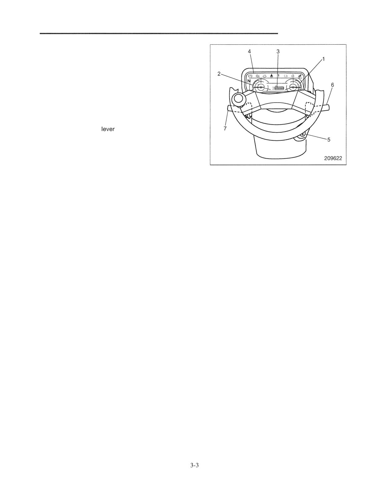
ELECTRICAL SYSTEM
Structure
Console box
1 Water temperature gauge
2 Fuel gauge
3 Various warning lights
4 instrument panel
5 Starter switch
6 Lighting switch, turn signal switch
7 Forward-reverse
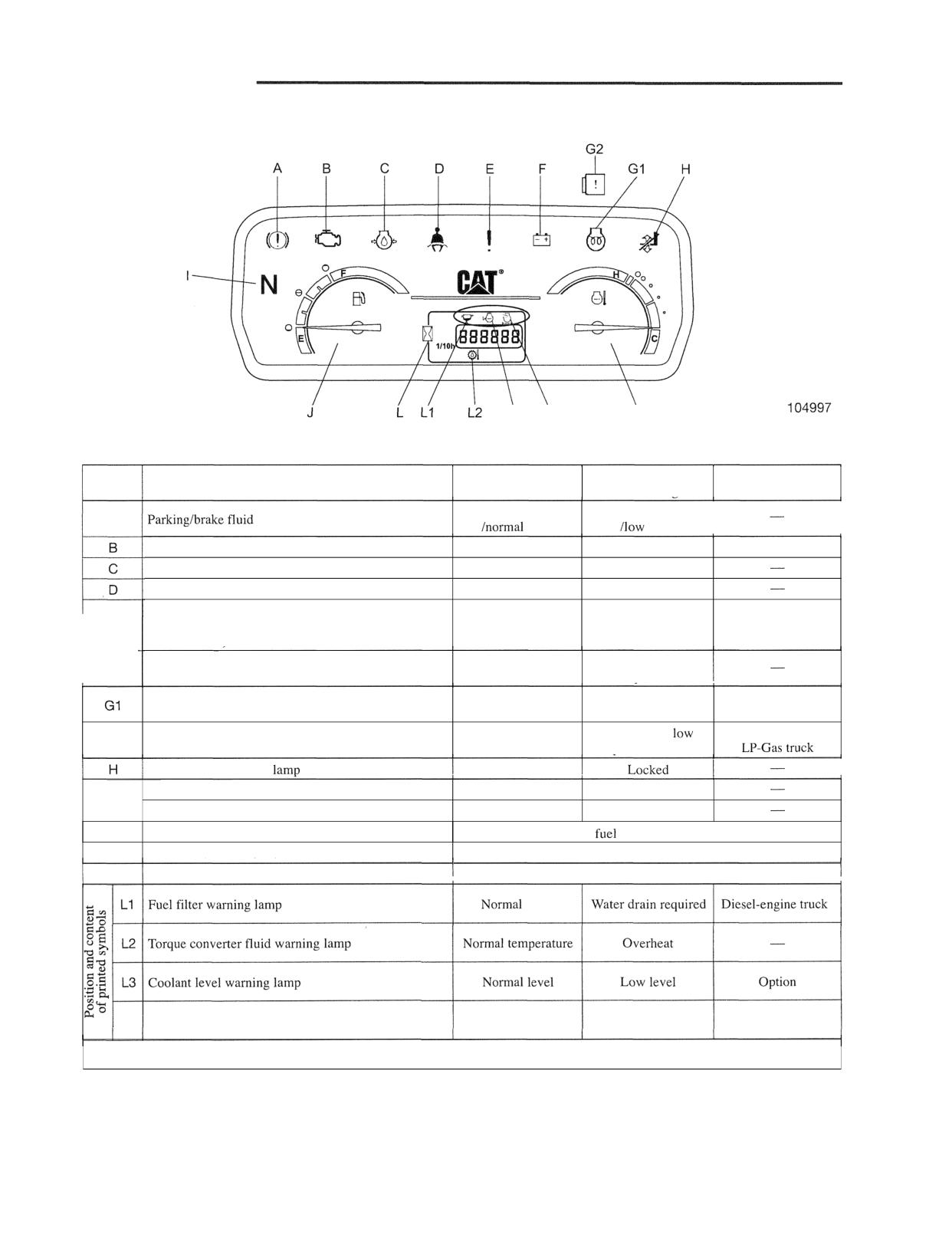
ELECTRICAL SYSTEM
Function of Instrument Panel
i3 i4
K
Description of function
When illuminated
Code
Name of monitor
When not illuminated
Remarks
or flashing
Parking brake released
Parking brake applied
A
warning lamp
level
level
I
ECM warning lamp
Normal
ECM abnormal
Gasoline-engine truck
Engine oil pressure warning lamp
Normal oil pressure
Low oil pressure
Seat belt reminder warning lamp
Fastened
Not fastened
Multi-purpose warning lamp (illuminates when
warnings indicated by printed symbols occur or minor
Normal
Malfunction
Printed symbol
failures occur)
Abnormal charging
Charge warning lamp
Normal charging
system
Engine being
Glow pilot lamp
Preheating completed
Diesel-engine truck
preheated
LPG fuel level
or
G2
LP-Gas warning lamp
Normal
pressure low
Loadiunload interlock
Free
Fr, Re interlock lamp
Free
Locked (flashing)
I
Neutral lamp
For R
Neutral
J
Fuel gauge
Indicates remaining
amount with key in "ON" position.
K
Water temperature gauge
Indicates "Overheat" condition if pointer enters the red zone.
L
Liquid crystal (normally acting as hour meter)
Indicates operating hours with key in "ON" position.
L4 Clogged air cleaner element warning lamp
Normal element
Clogged
Option
When major failures occur, bulbs A, C, D, E, and H simultaneously flash.
Inspection method of blown bulbs for Instrument panel
All warning and indicator lamps are normal if they illuminate when the starter switch is turned ON, and no bulbs are
blown.
3-4
ELECTRICAL SYSTEM
Major Electrical Components
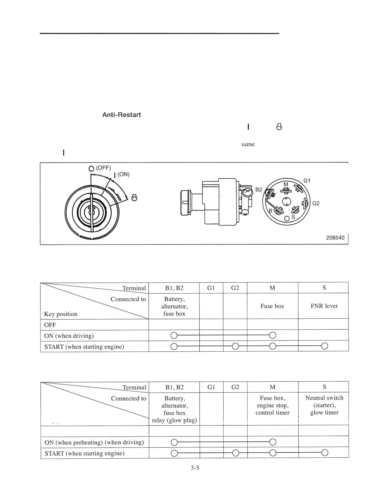
Starter switch
The diesel-engine truck, which uses a distributor type injection pump, is provided with an engine automatic stop
mechanism of the fuel cut off system located by the starter switch.
The gasoline-engine truck also has an engine automatic stop mechanism of the fuel cutoff system.
Starter switch (with
Lock)
This switch has a built-in anti-restart lock, so the key cannot be turned from (ON) to
(START) position while
the engine is running. This prevents starter breakage or flywheel damage caused by an operator re-starting the truck
when the engine is running. The gasoline- and diesel-engine models use the
starter switch. In the diesel-engine
models, (ON) position of the switch is for energizing the glow plugs.
(START)
Connection Table
Gasoline-engine truck
Diesel-engine truck
Key position
OFF
ELECTRICAL SYSTEM
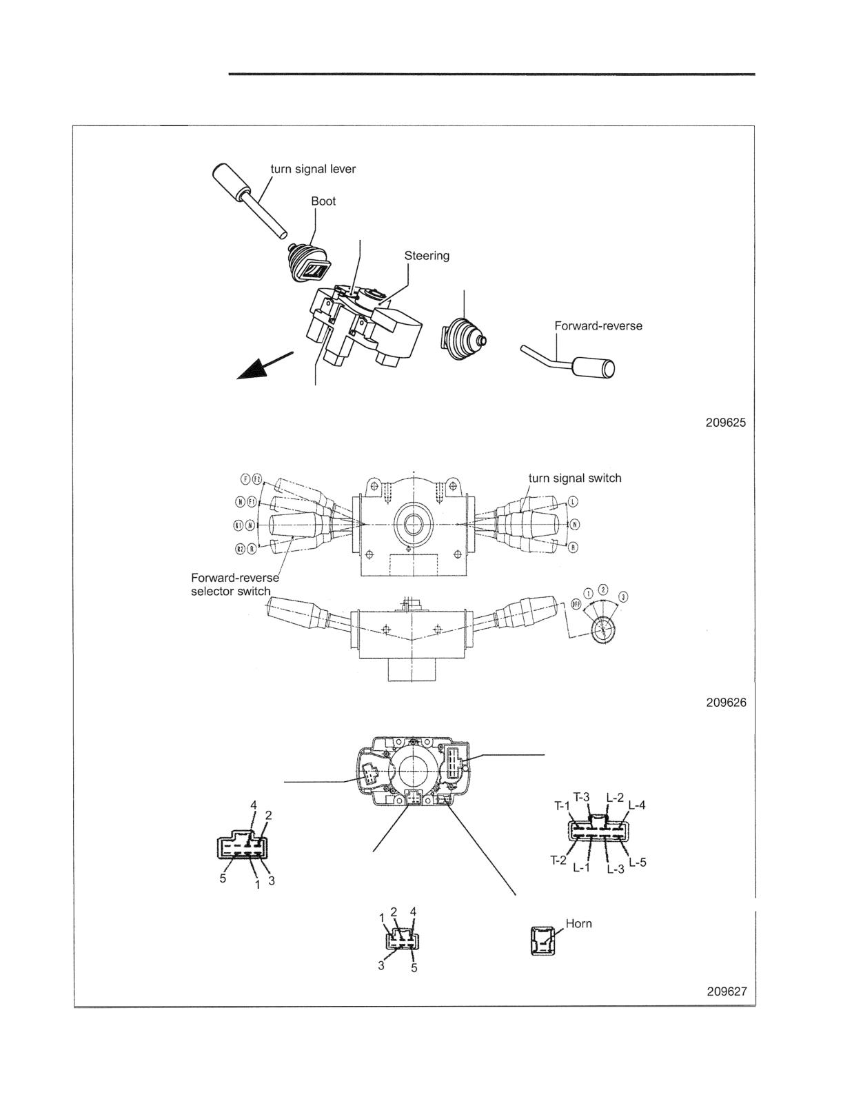
Lighting switch and turn signal switch
Lighting and
Horn contact
I
angle sensor
Boot
lever
Forward of truck
Lighting switch, turn signal switch
Forward of truck
4
Lighting switch,
Lighting switch and
Forward-reverse
turn signal switch
selector switch
/
Steering angle sensor
Horn contact
ELECTRICAL SYSTEM
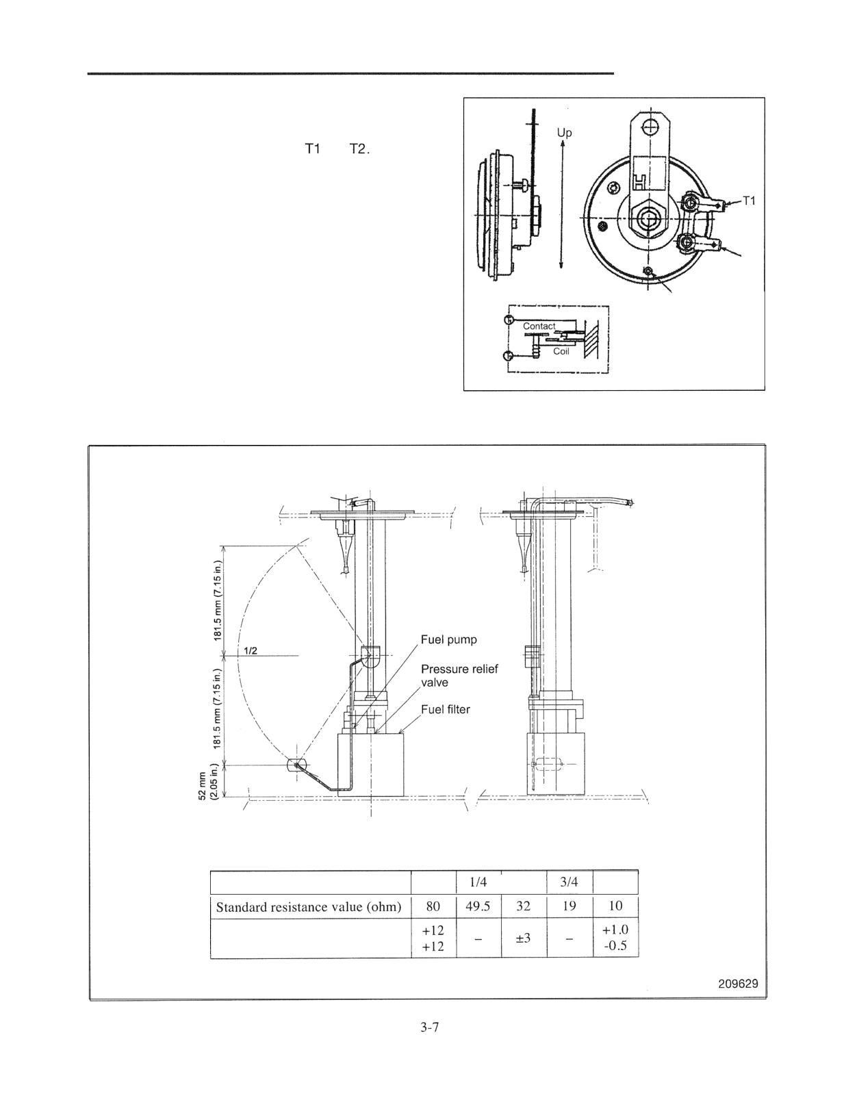
Morn
Check that the horn sounds when applying the specified
voltage to both terminals of the horn,
and
Replace the horn if it does not sound or its sound is
abnormal.
Operating voltage: DC 12 V
Note: The installed position in an actual truck is as per the
illustration.
T2
Down
Vent hole
209628
Tank Unit
Referential Standards
Float position
E
112
F
I
I
Tolerance (ohm)
ELECTRICAL SYSTEM
Brake fluid sensor
Refer to the brake system.
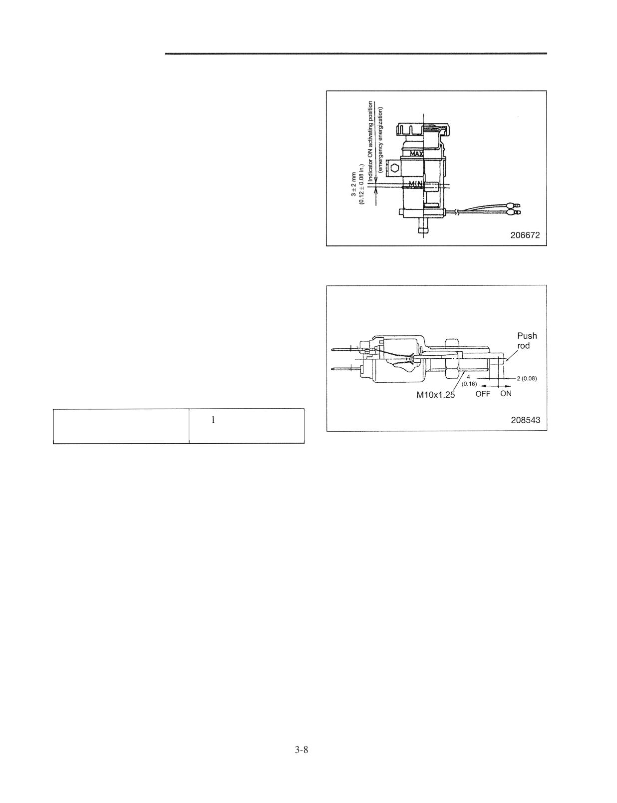
Stop lamp switch
Connect a tester across the terminals and check that the
Unit : mm (in.)
lamps turn ON and OFF when the push rod extended
projection is to the specified value.
Measure the insulation resistance value across the terminals
when the push rod is pushed in.
Replace the switch if the measured insulation resistance
value is not more than the value listed below.
(illuminates)
M ohm or more
Insulation resistance value
(at 500 V megger)
Rated voltage: DC 12 V
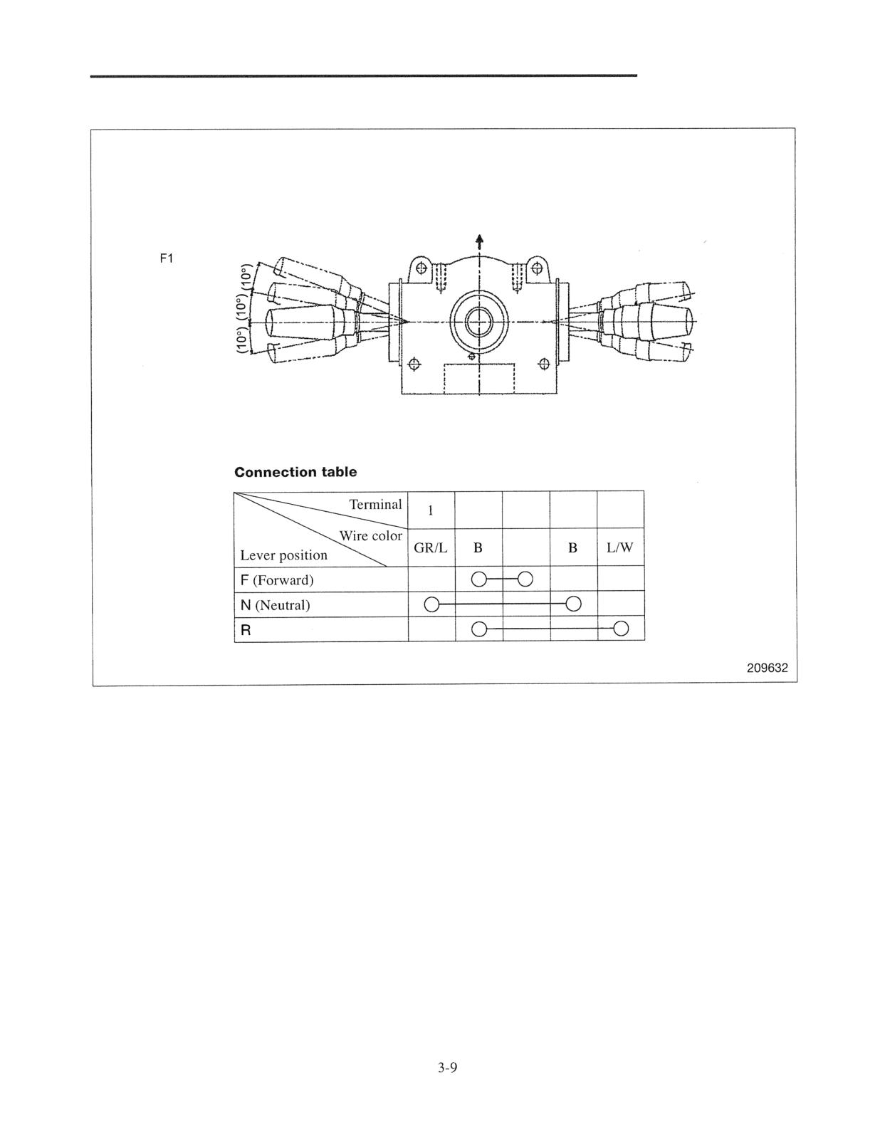
ELECTRICAL SYSTEM
Forward-reverse lever assembly
Forward of vehicle
Forward 1
F2 Forward 2
N Neutral
R Reverse
2
3
4
5
GIR
(Reverse)
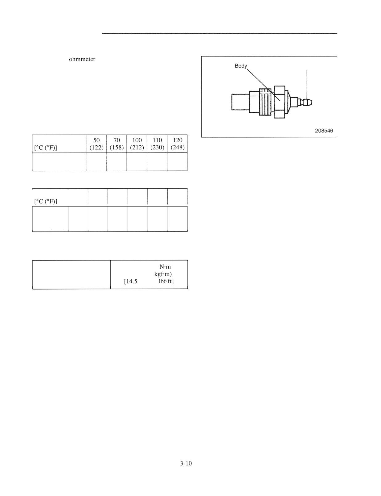
ELECTRICAL SYSTEM
Sender unit (engine coolant temperature)
1. Apply an
between the terminal and body of
the sender unit and check for continuity (resistance
Terminal
value).
2. Replace the sending unit if there is no continuity or the
measured resistance value is outside the standard
resistance value.
Note: The illustration is for a gasoline-engine truck.
Gasoline-engine truck
Temperature
Standard resistance
136
66
27.2
20.5
17.2
value (ohm)
Diesel-engine truck
Temperature
50
60
80
100
106
120
(122)
(140)
(176)
(212)
(222.8)
(248)
Standard
resistance
(80)
56.3
(29.5)
(16.5)
14.3
(10)
value (ohm)
3. When installing the sending unit, tighten it to the
specified torque.
19.6 to 27.4
Sending unit tightening
(2.0 to 2.8
torque
to 20.2
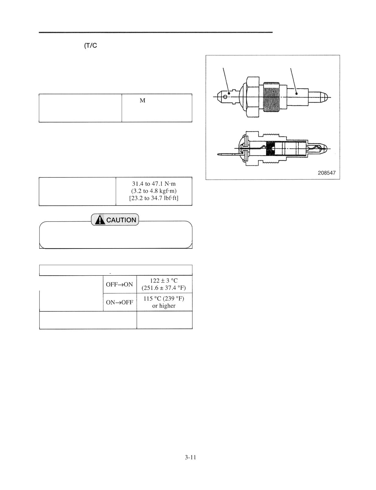
ELECTRICAL SYSTEM
Thermoswitch
oil)
Apply an ohmmeter between the terminal and body and
Terminal
Body
check for continuity (resistance value). Replace the
thermoswitch if the measured insulation resistance value is
not more than the value listed in the table below.
1
ohm or more
Insulation resistance value
(with contact OFF)
(at 500 V megger)
Internal resistance: 0.5 ohm or less (with contact ON)
Allowable load: 0.5 A
Note: When installing the thermoswitch, tighten it to the
specified torque.
Tightening torque
Replace the thermoswitch if it was dropped or
abused.
Main specifications
Operating temperature
Insulation resistance
1 M ohm or more
(with contact OFF)
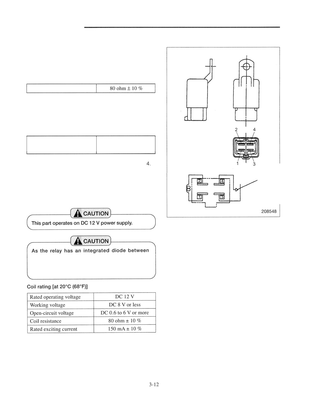
ELECTRICAL SYSTEM
Power relay (Backup lamps)
Inspection of coil
Apply an ohmmeter across terminal 1 and terminal 2 and
measure the resistance value of the relay coil. If there is no
continuity or the resistance value measured is outside the
standard resistance value, replace coil.
Resistance value of coil
Inspection of contact
1. Measure the insulation resistance value between
terminal 3 and terminal 4. Replace the contact if the
measured insulation resistance value is not more than
the value listed in the table below.
10 M ohm or more
Insulation resistance value
(at 500 V megger)
Connection diagram
2. Apply an ohmmeter across terminal 3 and terminal
3. When applying a voltage of 12 V ON and OFF across
terminal 1 and terminal 2 under the above condition,
Diode
check to see if the relay activates to cause continuity
between terminal 3 and terminal 4. Replace the relay if
it was dropped or abused.
terminals, be careful about the polarity when
inspecting. Replace the relay if an impact is given
to it or if it is dropped.
SYSTEM
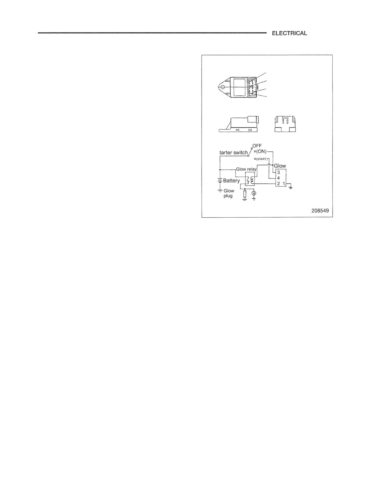
Glow timer (diesel-engine truck)
Inspection of output time when starter switch is
turned to ON
3 (1.25 Br: MTM truck)
(1.25 BY: ATM truck)
When an ohmmeter is applied to terminal 2 and terminal 1
4 (1.25 WL)
and a voltage of 12 V is applied between terminal 3 and
1 (0.85 B)
terminal 1 , there is continuity between terminal 2 and
2 (1.25 BR)
terminal 1 for 1.5 seconds at room temperature. Replace
the glow timer with a new one if it does not operate
properly.
Inspection of output time when starter switch is
turned to START
Starter switch
When an ohmmeter is applied to terminal 2 and terminal 1
and a voltage of 12 V is applied between terminal 4 and
timer
terminal 1 , there is continuity between terminal 2 and
terminal 1 for 5 seconds. Replace the glow timer with a
new one if it does not operate properly.
Glow
indicator
lamp
Rated voltage: DC 12 V
ELECTRICAL SYSTEM
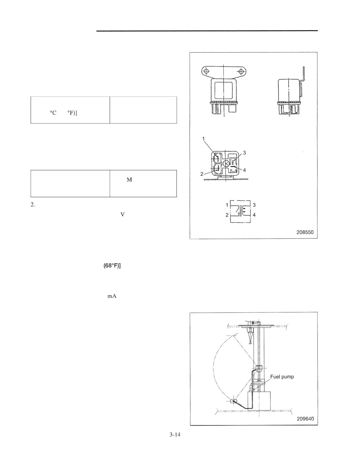
Glow relay (diesel-engine truck)
lnspection of coil
Apply an ohmmeter across terminal 3 and terminal 4 and
measure the resistance value of the relay coil. If there is no
continuity or the measured resistance value is outside the
standard resistance value. Replace the coil.
Resistance value of coil
52 ohm
[at 20
(68
lnspection of contact
1. Measure the insulation resistance value between
terminal 1 and terminal 2. Replace the contact with a
new one if the measured insulation resistance value is
not more than the value listed in the table below.
1
ohm or more
Insulation resistance valve
(at 500 V megger)
Connection diagram
Apply a tester to terminal 1 and terminal 2.
3. When applying a voltage of 12 ON and OFF across
terminal 3 and terminal 4 under the above condition,
check to see if the relay activates to cause continuity or
not between terminal 1 and terminal 2. Replace the
relay with a new one if it does not activate properly.
Coil rating [in case of 20°C
Rated operating voltage: DC 12 V
Coil resistance: 52 ohm
Rated exciting current:
80
Fuel pump (gasoline-engine truck)
ELECTRICAL SYSTEM
Solenoid valve (for speed selector valve)
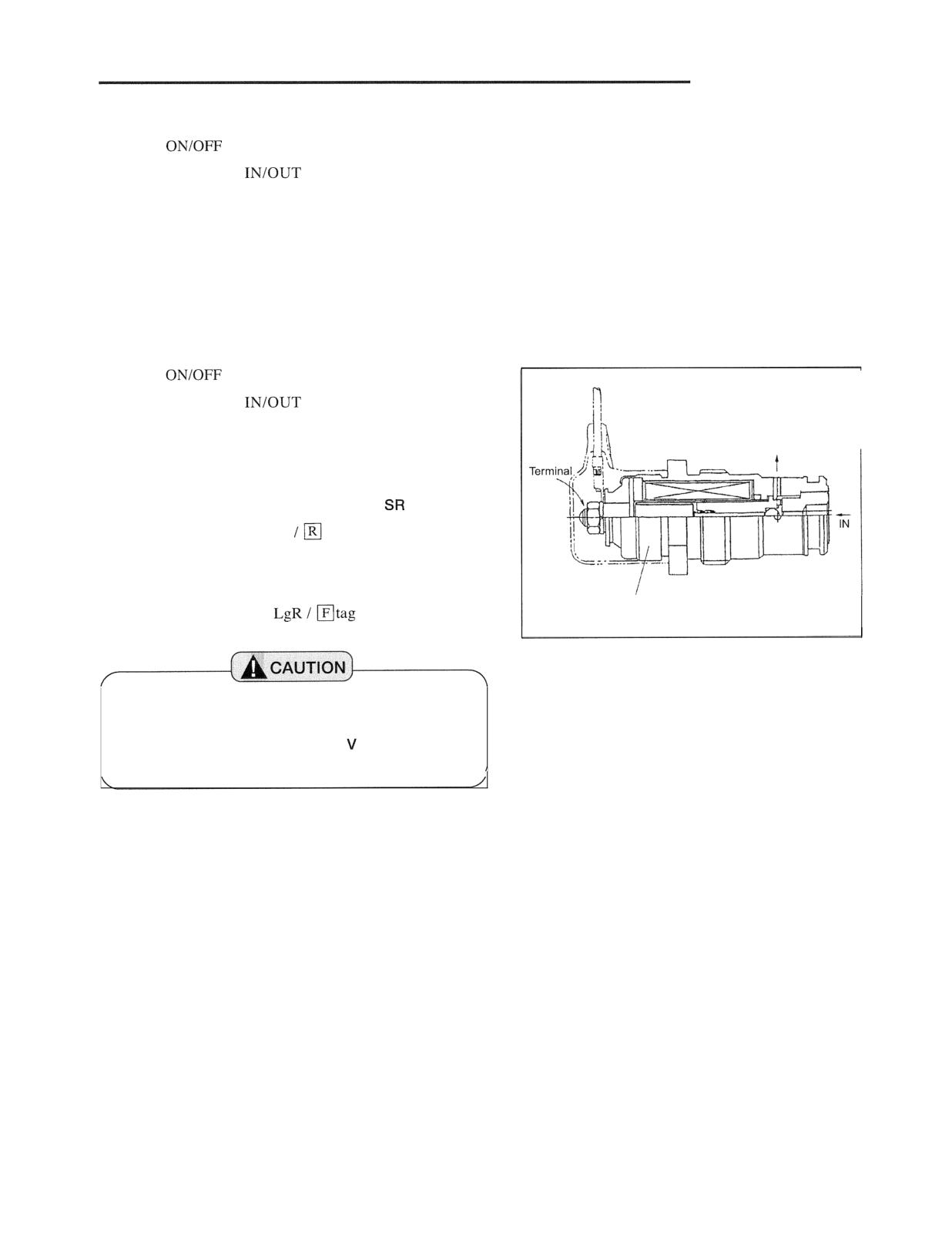
This is an
valve (normal open type).
The valve opens the
circuit in a non-energized
condition.
Rated operating voltage: DC 12V (gasoline-engine truck,
resin color: grey)
: DC 12V (diesel-engine truck,
resin color: brown)
Solenoid valve (for SR-SF selector valve)
This is an
valve (normal open type).
The valve opens the
circuit in a non-energized
condition.
Rated operating voltage: DC 12V
OUT
Wiring to the solenoid valve terminal on
side
Wire gauge and color 1.25 Br
tag is attached.
Wiring to the solenoid valve terminal on SF side
Mark of 12 V NO
Wire gauge and color 1.25
is attached.
208536
The valve has an identification mark "1 2 V NO" on
the body side.
Be careful not to supply DC 24 to the valve to
avoid damage.
ELECTRICAL SYSTEM
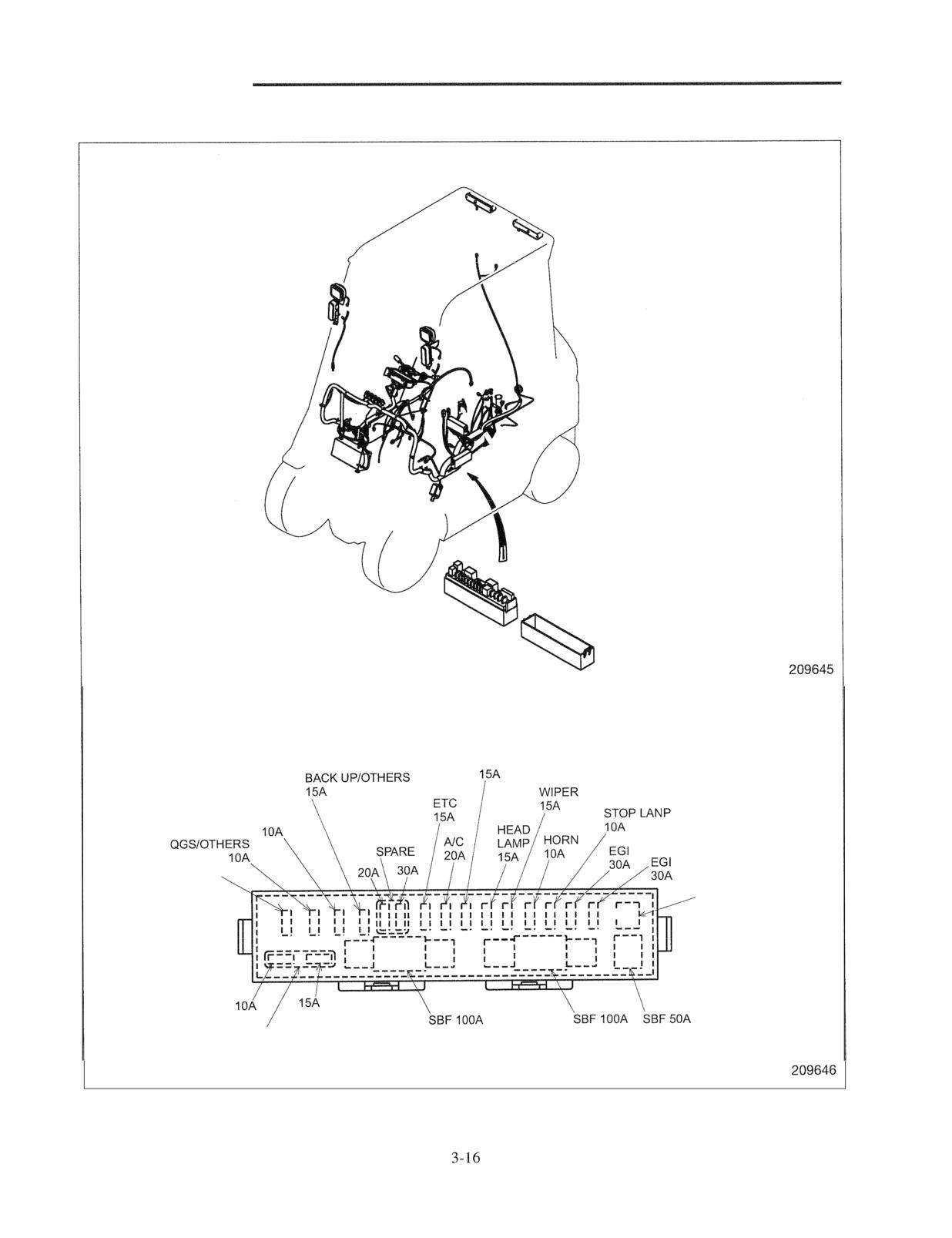
Fuse Box
Fuse box, Fuse
WORKING
LAMP
METER PANEL
VCM
20A
,FUSE
PULLER
I
SPARE
BATTERY
ALTNR
GLOW
ELECTRICAL SYSTEM
Lamp Bulb Specifications
License plate lamp
Instrument panel lamps
ELECTRICAL SYSTEM
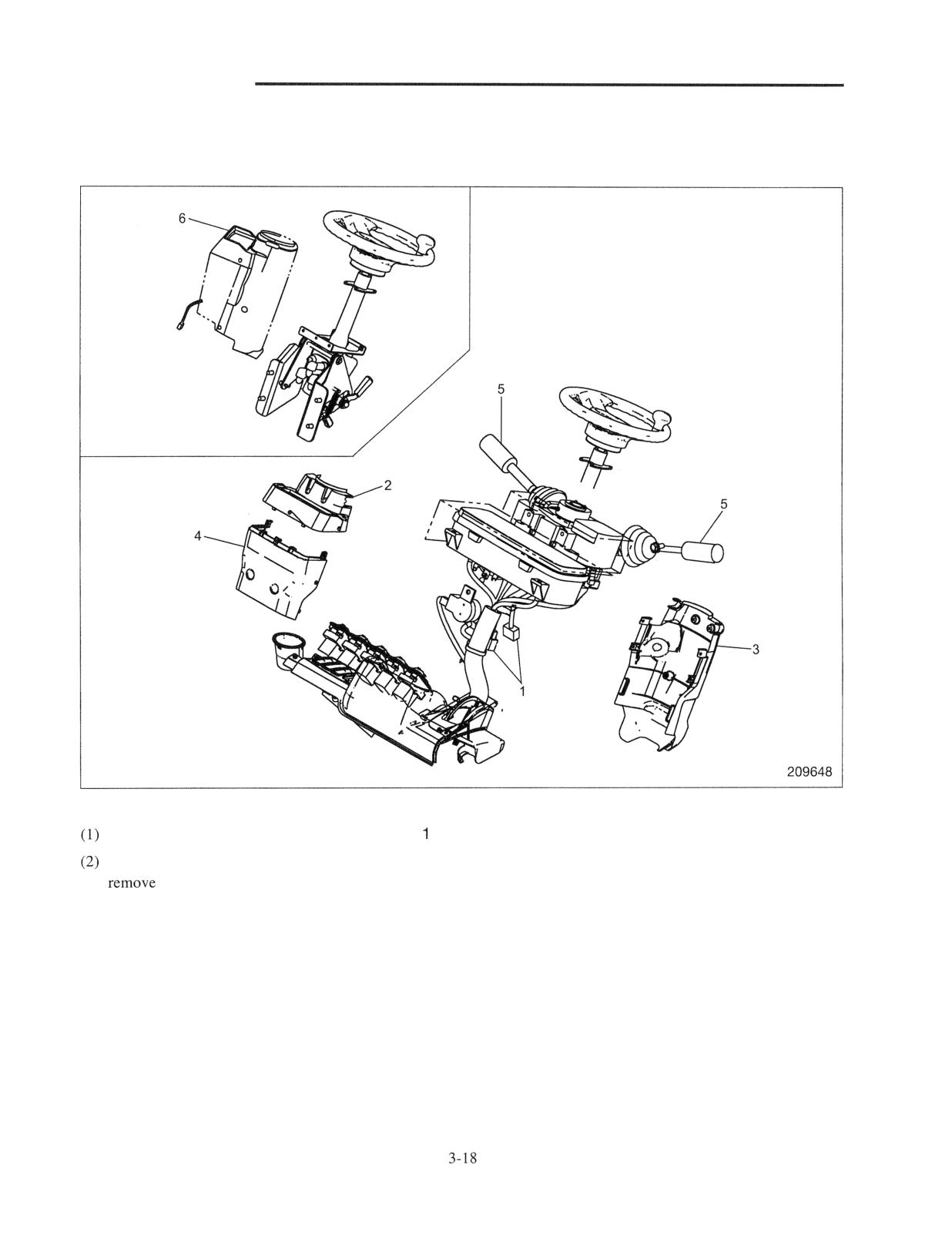
Console Box
Disassembly
Disconnect the electrical wiring from connector .
Remove the screw using a flatblade screwdriver and
cover 2.
(3) Remove the screw and then, remove cover (U-Re) 3.
(4) Remove the screw and then, remove cover (U-Fr) 4.
(5) Remove the forward-reverse lever (FNR lever) and
turn signal lever 5.
(6) Rernove the bolt and then, remove console box
assembly 6.
Reassembly
Follow the disassembly sequence in reverse.
ELECTRICAL SYSTEM
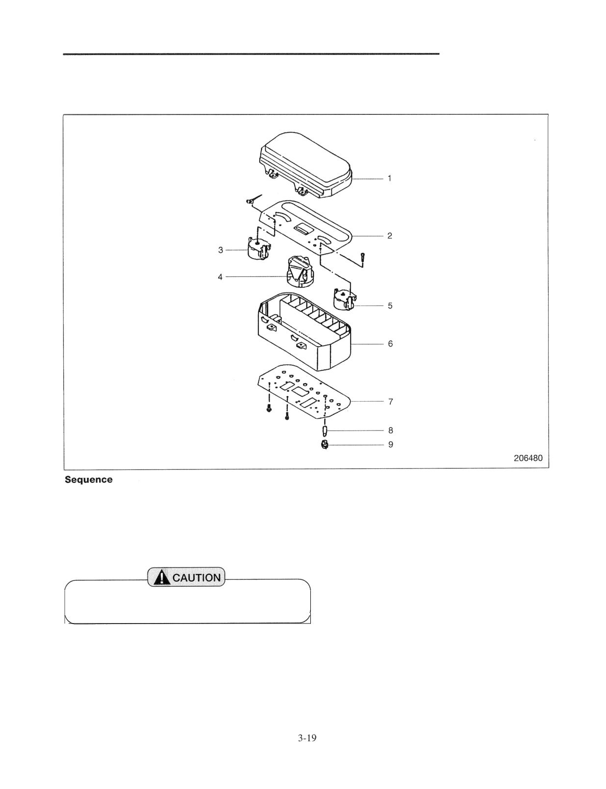
instrument Panel
Disassembly
1 Meter cover
6 Meter case
2 Dial
7 Rigid board
3 Water temperature gauge
8 Bulb
4 Liquid crystal
9 Socket
5 Fuel gauge
Be careful not to damage the rigid board when
disassembling the instrument panel.
Reassembly
Bulb replacement
To reassemble the instrument panel, follow the reverse
For bulb replacement, remove the socket from the rigid
of disassembly procedure.
board by turning it counterclockwise. For configuration
of the indicator lights, refer to page 3-4.
ELECTRICAL SYSTEM
Battery Maintenance
1. State of charge and electrolyte specific gravity
adjustment
Specific gravity reading
State of charge
Adjustment
at 20°C
1.280 to 1.265
Fully charged
If difference in S.G. between any two cells is 0.020 or more,
discharge the battery to minimize the difference and then
recharge battery. Adjust S.G. during recharging.
1.260 to 1.225
One-half charged
Recharge battery and adjust electrolyte S.G. Make sure there
is neither faulty components, loosely connected cord or
corroded connection.
1.220 or below
Discharged
Recharge battery. If difference in S.G. is large, adjust it
during recharging.
If difference in S .G. is
A cell with a low S.G.
Recharge until voltage and S.G. stabilize and have remained
more than 0.040
is in
condition.
constant for more than 2 hours.
Electrolyte leakage,
During recharging, adjust S
to 1.280 to 1.265.
or
If difference in S.G. is more than 0.040 and a low S
is
electrolyte.
found in certain cells only, replace battery. After leaving
battery for 12 to 96 hours, conduct a high current discharge
test.
2. Specific gravity reading and state of charge
To check the battery for state of charge, take
Be sure to turn
hydrometer readings on its electrolyte. The battery may
switch before disconnecting or connecting the
be fully charged if the S.G. reading is 1.280 to 1.265 at
battery cables to prevent the IC regulator from
20°C (68°F). The state of charge can be told from the
way the electrolyte level goes down to expose the cell
plates. If addition of distilled water is necessary every
month or so, the battery is overcharged. If addition is
not required for more than 3 months, it is likely that the
battery is inadequately charged.
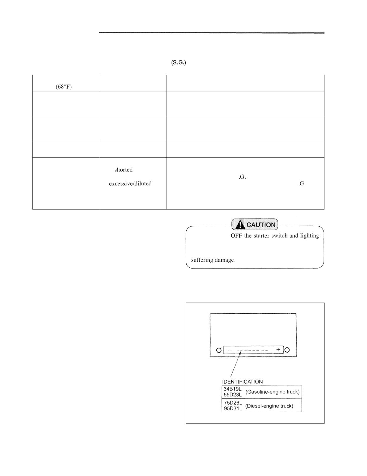
3. Charging precautions
(1) In slow charging, the charging current should be
about 1/10 the capacity of the battery to be charged.
000000
(2) In quick charging, the battery capacity in ampere
should not be exceeded.
(3) During charging, adjust the charging current to
prevent the electrolyte temperature from rising
beyond 45°C (113°F).
(4) When connecting the cables to the battery, begin by
installing the cable to the positive (+) terminal.
When disconnecting them from the battery, begin
by removing the cable for the negative (-) terminal.
209650
ELECTRICAL SYSTEM
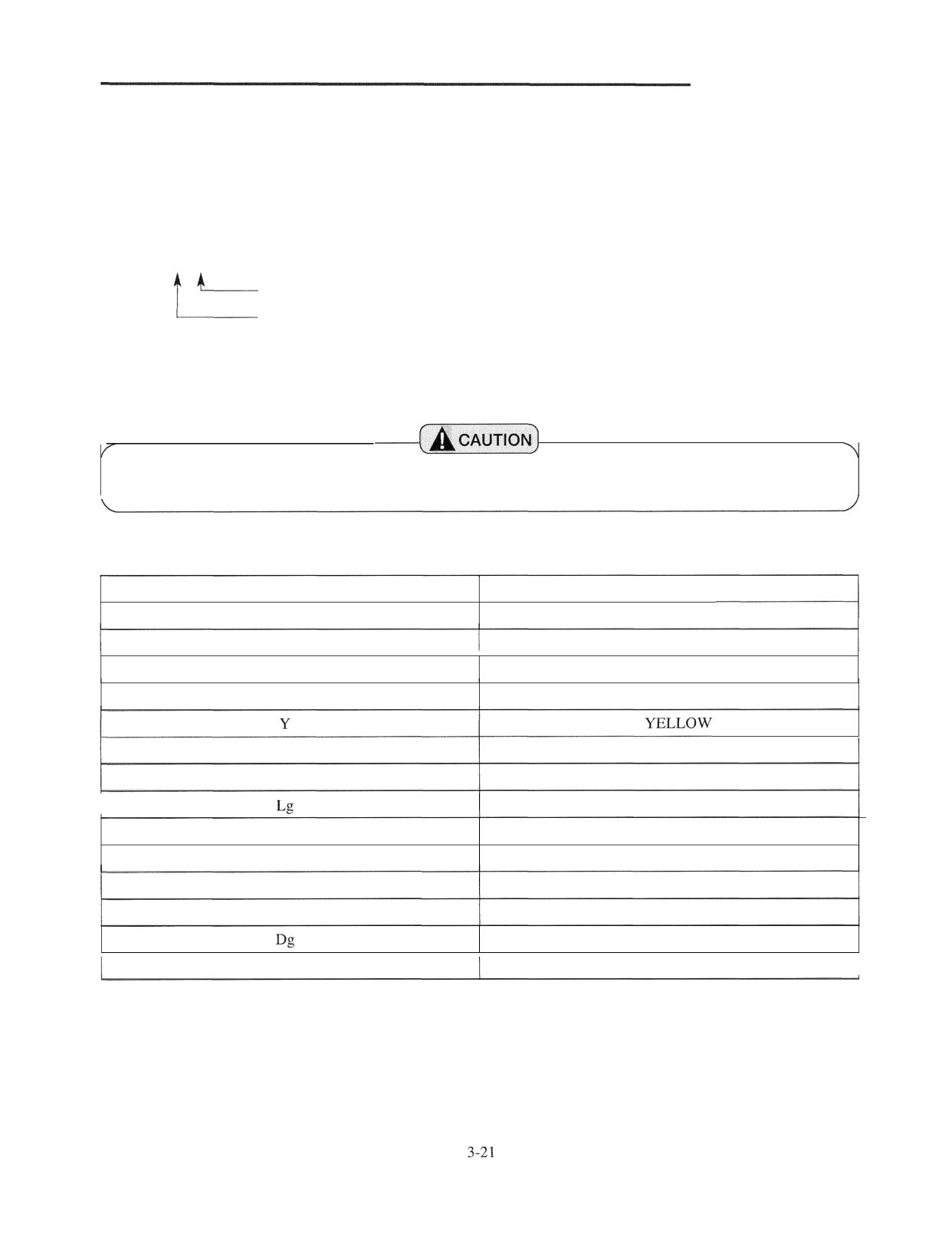
Wire Color
Wire colors listed in the table below show standard colors (base colors). For wiring composed of two colors, the first
color shows a base color and the second color a marking color.
Example: The wire color of BW shows that its base color is B with a marking W.
BW
Marking color
Base color
Note: For wiring identification, the same color, in principle, must be used for the circuit from the power supply to the
load.
Be careful that allowable current differs between solid wires and stranded wires even if they are of the
, same gauge.
List of wire colors
Wire color
Color
B
BLACK
W
WHITE
I
R
RED
G
GREEN
Br
BROWN
L
BLUE
LIGHT GREEN
I
0
ORANGE
P
PINK
Gr
GRAY
Lb
LIGHT BLUE
DARK GREEN
ch
CHOCOLATE
I
ELECTRICAL SYSTEM
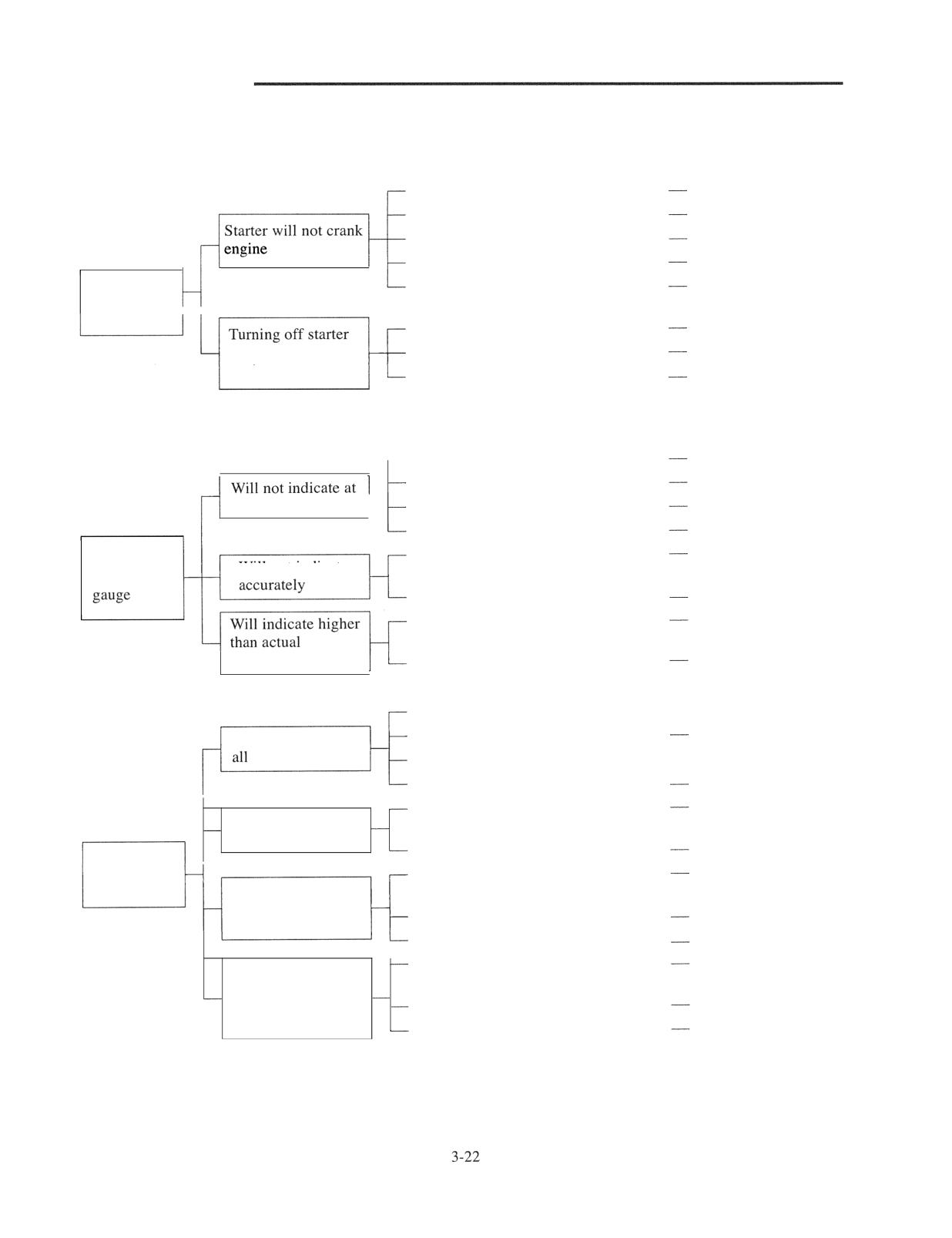
Troubleshooting
Starter System
Weak or dead battery
Recharge or replace.
Short or open circuit
Repair or replace.
Starter will not crank
Poor continuity in starter switch
Replace.
Starter or starter relay defective
Replace.
Forward-reverse lever not in neutral
Move lever to neutral
Starter switch
position
position.
Open or short circuit
Repair or replace.
switch will not stop
Engine stop solenoid defective
Replace or readjust.
engine
Control timer defective
Replace.
Gauges
-
Rigid board defective
Replace.
Open or short circuit
Repair or replace
all
Gauge internally defective
Replace.
Gauge unit defective
Replace.
Gauge or gauge unit not of the type
Replace to a correct
Water
Will not indicate
called for
one.
temperature
Loose terminal connection
Repair.
Circuit between gauge and gauge unit
Repair.
grounded
temperature
Gauge internally defective
Replace.
Rigid board defective
---- Replace.
Will not indicate at
Open or short circuit
Repair or replace.
Gauge internally defective
- Replace.
Gauge unit defective
Replace.
Gauge or gauge unit not of the type
Replace to a correct
Will not indicate
called for
one.
accurately
Loose terminal connection
Repair.
Fuel gauge
Circuit between gauge and gauge unit
Repair.
Will indicate "full"
open or short
regardless of amount
Gauge internally defective
Replace.
of fuel left in tank
Gauge unit defective
Replace.
Circuit between gauge and gauge unit
Repair.
Will indicate
grounded
"empty" regardless
of amount of fuel
Gauge unit defective
Replace.
left in tank
Gauge internally defective
Replace.
ELECTRICAL SYSTEM
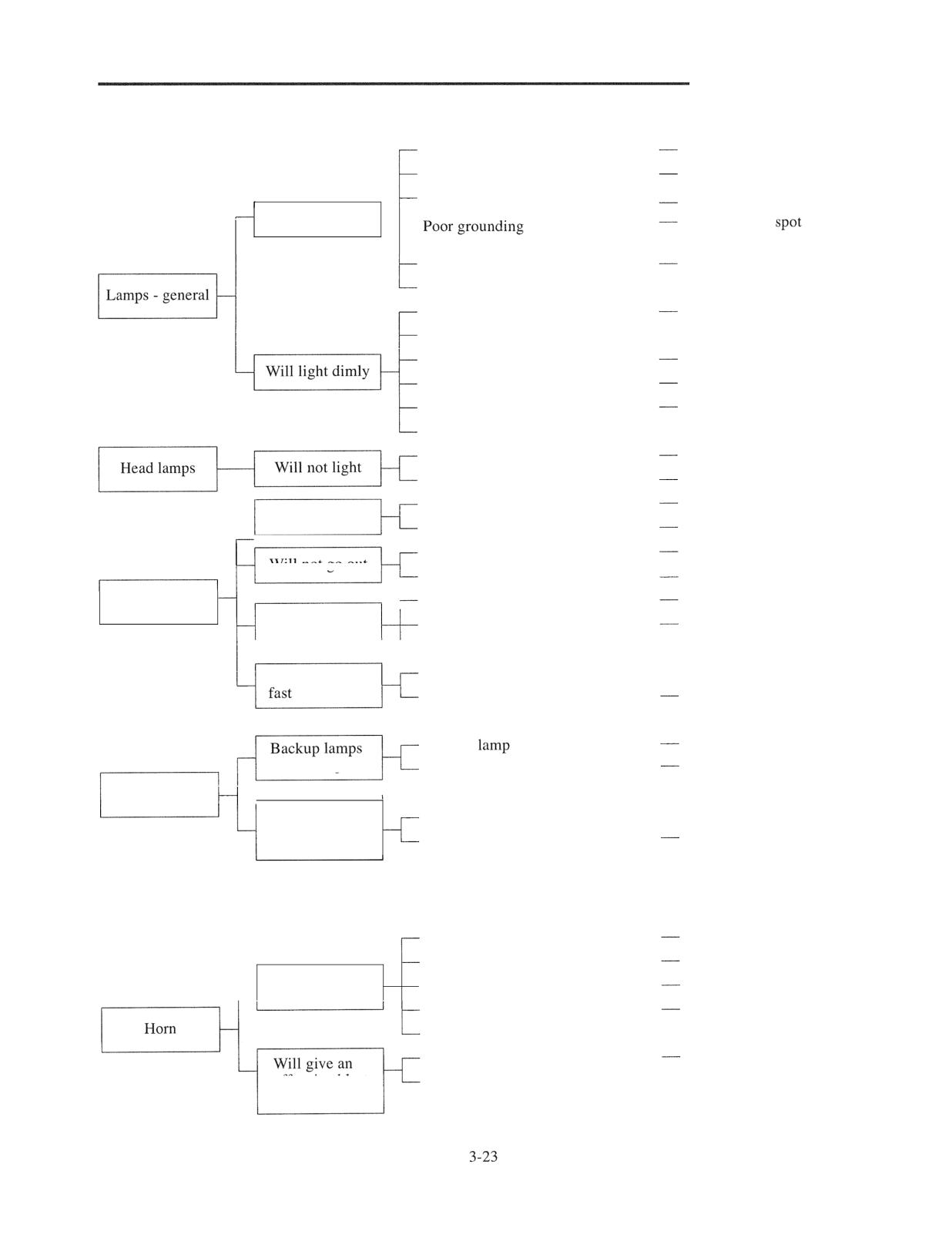
Lighting System
Weak or dead battery
Recharge or replace.
Fuses blown out
Check and replace.
,
Open or short circuit
Repair or replace.
Will not light
---
Clean ground
and
re-make connection.
Switch defective
Replace.
Bulbs burnt out
- Replace.
Weak battery
Check and recharge.
Contact points in switches defective
- Repair or replace.
Loose terminals
Repair.
Dirty lenses
Clean.
Waterdrops inside lenses
Dry and replace packings.
Bulbs expired in service life
- Replace.
Lighting switch defective
Replace.
Bulbs burnt out
Replace.
Turn signal switch defective
Replace.
Will not flicker
Turn signal relay defective
Replace.
Turn signal relay defective
Replace.
Will not go out
Bulbs burnt out
Replace.
Turn signals
Low wattage of bulbs
Replace to a correct one.
Will flicker too
Bulbs burnt out
Replace.
slow
Turn signal relay defective
- Replace.
Will flicker too
High wattage of bulbs
--- Replace to a correct one.
Turn signal relay defective
Replace.
Backup
switch defective
Repair or replace.
will not light
Bulbs burnt out
Replace.
Other lamps
License number
Lighting switch defective
- Replace.
plate lamp will
Bulb burnt out
Replace.
not light
Alarm Unit
Fuse blown out
Check and replace.
Open or short circuit
Repair or replace.
Will not sound
Horn switch defective
Replace.
Horn defective
Replace.
Horn button defective
- Repair or replace.
Horn switch defective
Replace.
offensive blast
Horn defective
-- Replace.
of sound
ELECTRICAL SYSTEM
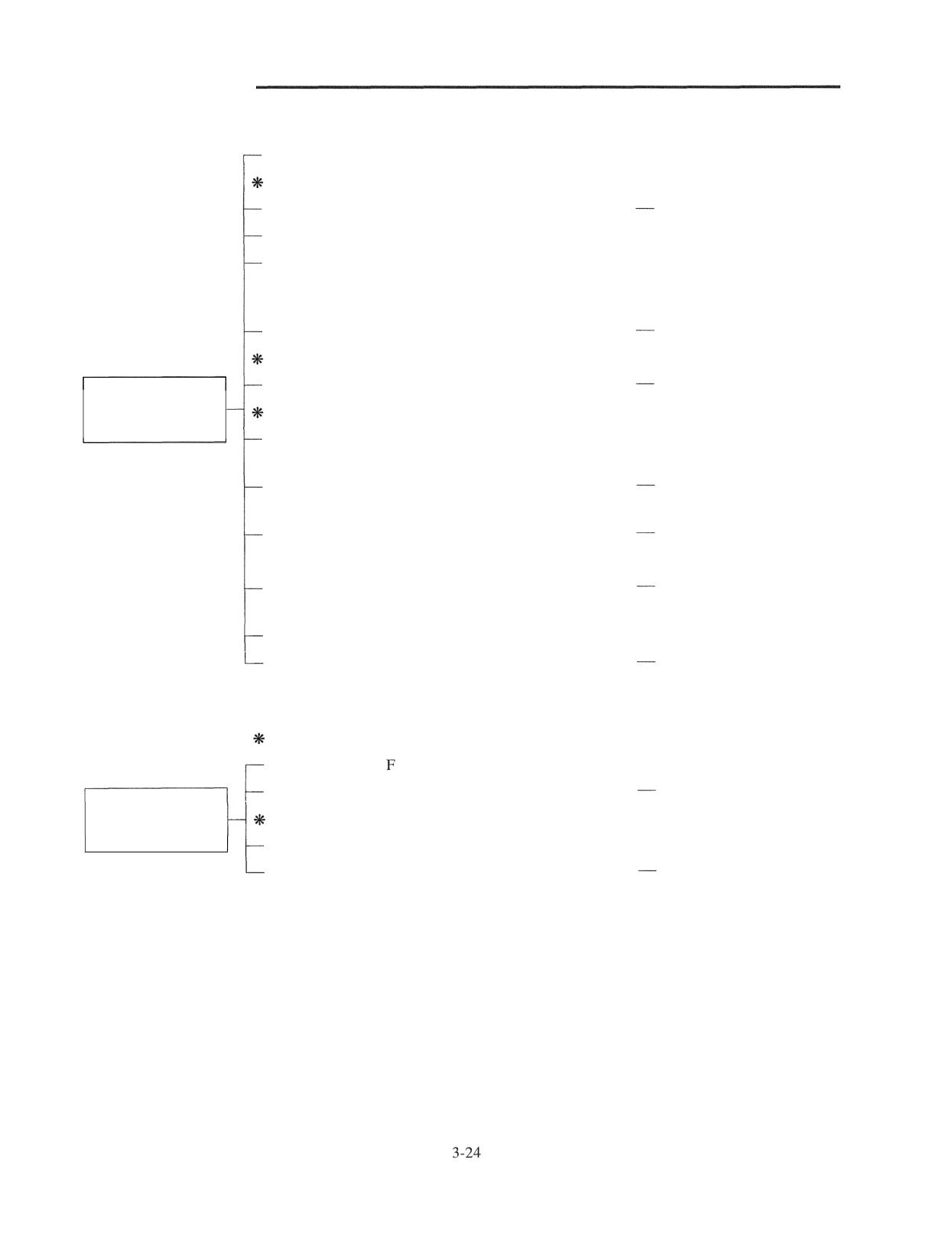
Battery
Drive belt slipping
- Readjust.
Alternator
Stator coil grounded or open-circuited
Repair or replace.
Rotor coil open
- Replace.
Brushes poorly seating on slip rings
- Replace brushes if worn.
Clean holder and polish
slip rings.
Diode ruptured
Replace.
Regulator
Regulated voltage setting too low
Replace.
Tends to run down
Battery
rapidly
Not enough electrolyte or wrong concentration of acid
- Refill and check specific
to water
gravity.
Battery cell plates deteriorated (forming, possibly
Replace.
internal short-circuit)
Terminal connections loose
Clean and retighten.
Wiring
Open or loose connection between starter switch and
Repair,
regulator IC terminal
Fuse blown, or loosely set in holder
- Replace and repair.
Open or loose connection between F terminals of
Repair.
regulator and alternator
Wiring
Regulator IC and terminals shorted or miswired
- Repair.
Poor grounding of regulator F terminal
Repair.
Tends to get
Regulator
overcharged
Pressure coil open-circuited
--- Replace.
Regulated voltage too high
Replace.

ELECTRICAL SYSTEM
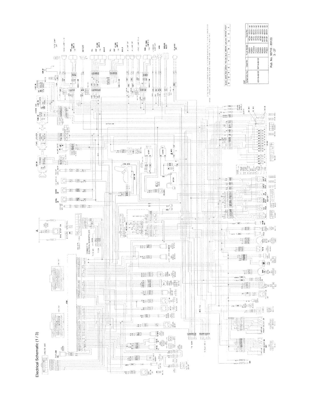
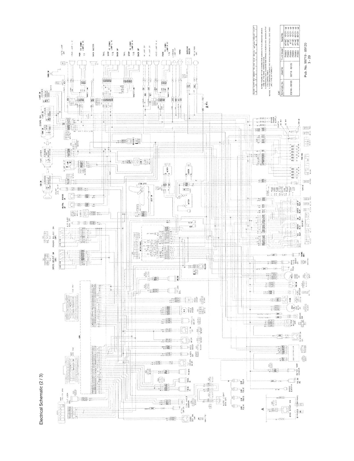
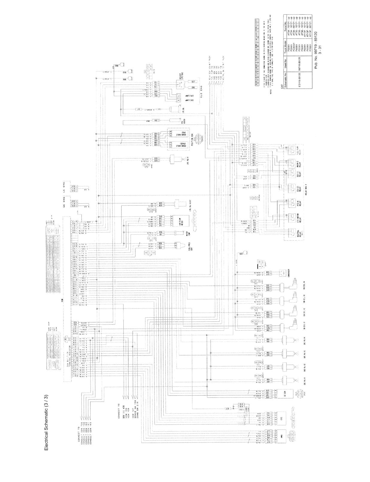
Electrical Schematic Diagram
Electrical Schematic Diagram (113): Gasoline-engine, Dual fuel gasoline-engine,
LPG-engine models
3 - 27
Electrical Schematic Diagram (213): Diesel-engine models
3 - 29
Electrical Schematic Diagram (313): Gasoline-engine, Dual fuel gasoline-engine,
LPG-enginemodels
3 - 31
CONTROLLERS
Outline
-
Main Functions
-
Service Tool Functions
-
Monitor
4 -
3
4-
3
Error Codes and Troubleshootings
4 -
5
Locations of Sensors and Switches
-
Others (Option)
- 14
CONTROLLERS
Outline
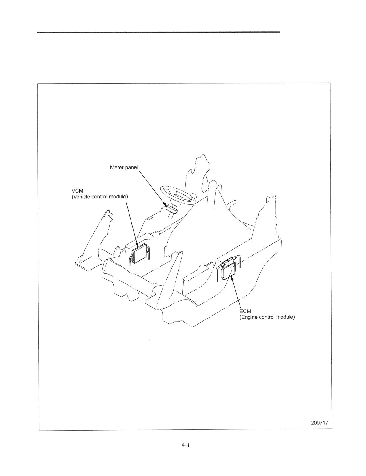
VCM and ECM control the vehicle and engine.
Controllers are located as shown below.
CONTROLLERS
Main
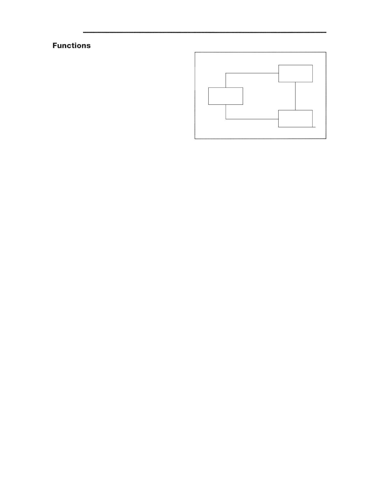
Meter panel, VCM and ECM are connected to each other
and their mutual communication works as a distributed
VCM
control system to control the truck.
METER
PANEL
ECM
Main functions of each controller are as follows:
Meter Panel
Located below the steering wheel and displays error codes.
Refer to "GROUP 3 ELECTRICAL SYSTEM" for other
functions.
VCM (Vehicle Control Module)
Located at the right side of the body and controls the
vehicle overall.
ECM (Engine Control Module)
Located at the left side of the body and controls the engine.
Refer to Engine Service Manual for details.
CONTROLLERS
Tool Functions
Monitor
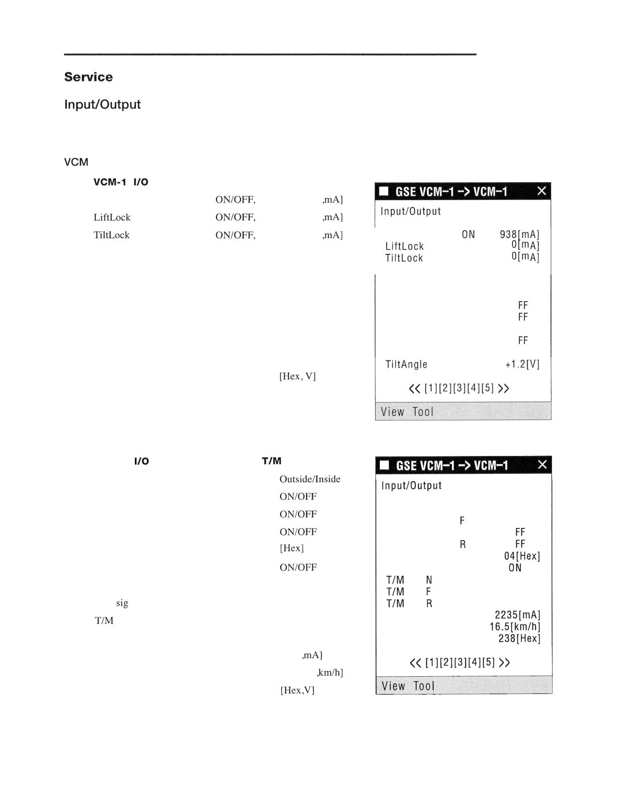
Monitors input and output of sensors and switches.
I.
Monitor: Mast control
Unload Sol
Feedback [Hex
monitor
Sol
Feedback [Hex
Feedback [Hex
Unload Sol
Sol
OFF
Sol
OFF
Lowering Speed SW
ONIOFF
Lowering Speed SW
ON
Lift Operation SW
ONIOFF
Lift Operation SW
ON
Mast High SW
ONIOFF
Tilt Operation SW
0
Mast Hight SW
0
Snow Mode SW
ONIOFF
Snow Mode SW
ON
Tilt Auto-stop SW
ONIOFF
Tilt Auto-stop SW
0
Tilt Operation SW
ONIOFF
Tilt Angle
2. VCM-1
Monitor: Engine and
control
Speed limit SW
monitor
Direction lever F
Speed limit SW
Outside
Direction lever N
Direction lever
ON
Direction lever R
Direction lever N
0
Direction lever
0
Direction lever
Direction lever
Accel SW
Accel SW
sig
0 FF
sol
ON
TIM
N
ONIOFF
sol
0FF
TIM sol cur
sol F
ONIOFF
Speed sensor
TIM sol R
ONIOFF
Speed sensor err
TIM sol cur
[Hex
Speed sensor
[Hex ,Hz
Speed sensor err
Note: "Hex" denotes hexadecimal digit.
CONTROLLERS
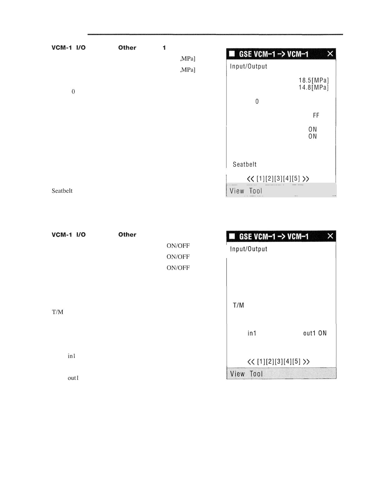
3.
Monitor:
control
Oil press MAIN
[Hex
monitor
Oil press LIFT
[Hex
Oil press MAIN
Oil press LIFT
Weight set SW
ONIOFF
Enter SW
ONIOFF
Weight set SW
OFF
Enter SW
OFF
Next SW
ONIOFF
Next SW
0
Auto light sig
Auto light sig
ONIOFF
Auto light OUT
Auto light OUT
ONIOFF
Seat SW
ON
Seat SW timer
ON
SW
ON
Seat SW
ONIOFF
Seat SW timer
ONIOFF
1
SW
ONIOFF
i
4.
Monitor:
control 2
Park brake alarm
I
monitor
Over load alarm
Park brake alarm
OFF
Over speed alarm
Over load alarm
OFF
Over speed alarm
OFF
Coolant low SW
ONIOFF
Coolant low SW
OFF
Air cleaner SW
OFF
Air cleaner SW
ONIOFF
warning SW
0
FF
warning SW
ONIOFF
Fuel warning SW
OFF
Park brake SW
OFF
Fuel warning SW
ONIOFF
Park brake SW
ONIOFF
AUX
OFF
AUX
AUX in2 ON
AUX out2 OFF
AUX out3 OFF
AUX
ONIOFF
AUX in2
ONIOFF
AUX
ONIOFF
AUX out2
ONIOFF
AUX out3
ONIOFF
CONTROLLERS
Error Codes and
Error Code Display
All the error codes detected by VCM are displayed.
Troubleshooting
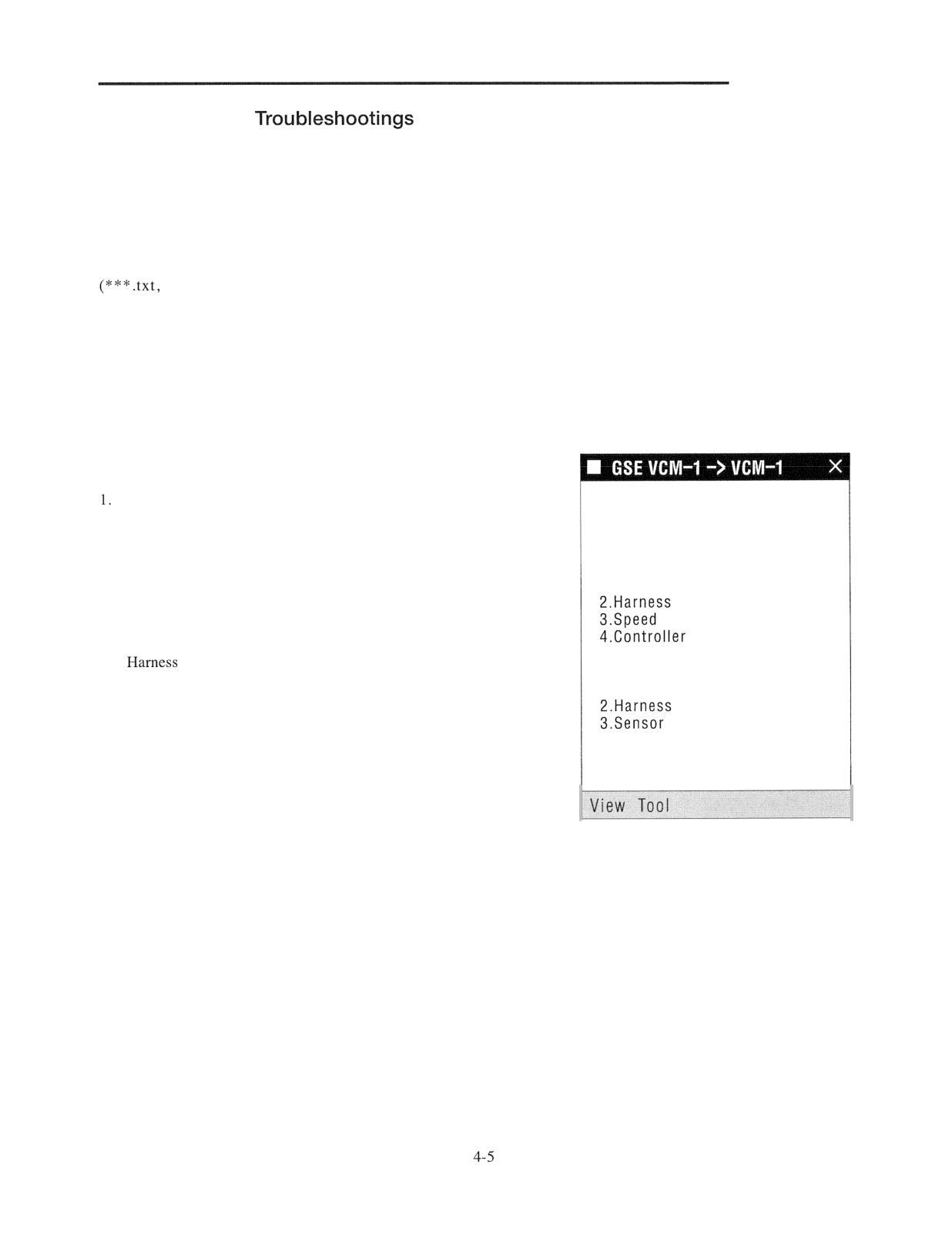
Tapping a displayed error code or error name reads the text file
which can be edited with a Windows application)
corresponding to the error code and displays the troubleshooting
screen specific to the error code. If one screen cannot
accommodate all data, the screen can be scrolled. The screen
specifications are shown below. The table in the following pages
lists the probable causes and check points for error codes.
Error code F34 (speed sensor error)
Estimated cause
Connector contact error
Troubleshooting
2. Harness error
F34 Speed sensor err
3. Speed sensor error
Estimated cause
4. Controller error
1 .Connector contact bad
bad
Check items
sensor bad
1. Connector connection
bad
2.
continuity
Check item
3. Sensor continuity
1.Connector connection check
connection check
connection check
CONTROLLERS
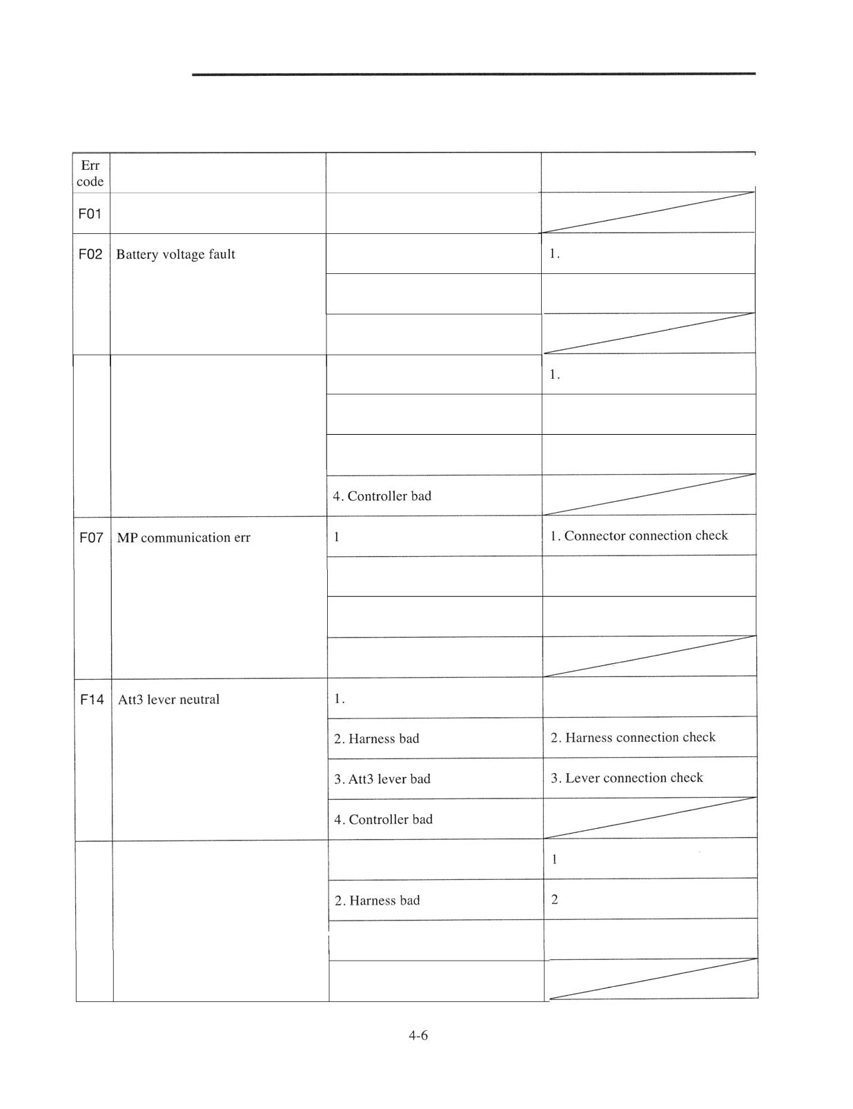
Error Codes and Troubleshootings are shown below.
Refer to "Locations of Sensors and Switches" on later pages.
Description
Probable cause
Check point
Memory err
1. Controller bad
1. Connector contact bad
Connector connection check
2. Harness bad
2. Harness connection check
3. Controller bad
F03
VCM communication err
1. Connector contact bad
Connector connection check
2. Harness bad
2. Harness connection check
3. VCM Controller bad
3. Communication line check
. Connector contact bad
2. Harness bad
2. Harness connection check
3. Meter panel bad
3. Communication line check
4. Controller bad
Connector contact bad
1. Connector connection check
F16 Shift lever fault
1. Connector contact bad
. Connector connection check
. Harness connection check
3. Shift lever check
3. Shift lever bad
4. Controller bad
CONTROLLERS
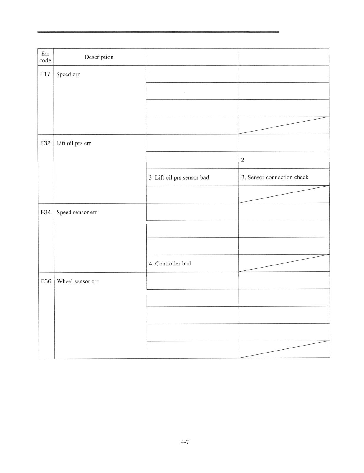
Probable cause
Check point
1. Connector contact bad
1. Connector connection check
2. Harness bad
2. I-Iarness connection check
3. Speed sensor bad
3. Sensor connection check
4. Controller bad
1. Connector contact bad
1. Connector connection check
2. Harness bad
. Harness connection check
4. Controller bad
1. Connector contact bad
1. Connector connection check
2. Harness bad
2. Harness connection check
3. Speed sensor bad
3. Sensor connection check
1. Connector contact bad
1. Connector connection check
2. Harness bad
2. Harness connection check
3. Wheel sensor bad
3. Sensor connection check
4. Joint and link bad
4. Joint and link check
5. Controller bad
CONTROLLERS
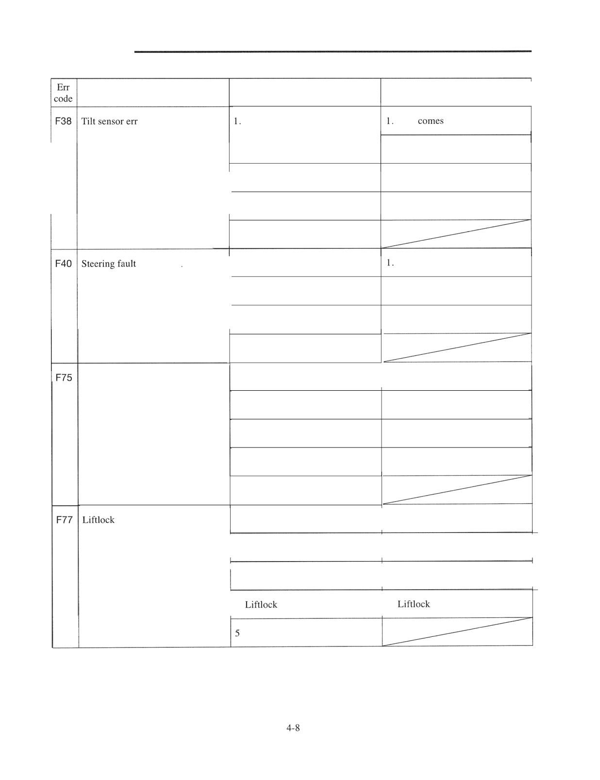
Description
Probable cause
Check point
F38 Tilt sensor err
Connector contact bad
Link
and damage check
2. Connector connection check
2. Harness bad
3. Harness connection check
3. Tilt sensor bad
4. Sensor connection check
4. Controller bad
1. Connector contact bad
Connector connection check
2. Harness bad
2. Harness connection check
3. Wheel sensor bad
3. Sensor connection check
4. Controller bad
Unload sol err
1. Connector contact bad
1. Connector connection check
2. Diode bad
2. Diode connection check
3. Harness bad
3. Harness connection check
4. Unload sol bad
4. Unload sol connection check
5. Controller bad
sol err
1. Connector contact bad
1. Connector connection check
2. Diode bad
2. Diode connection check
3. Harness bad
3. Harness connection check
4.
sol bad
4.
sol connection check
. Controller bad
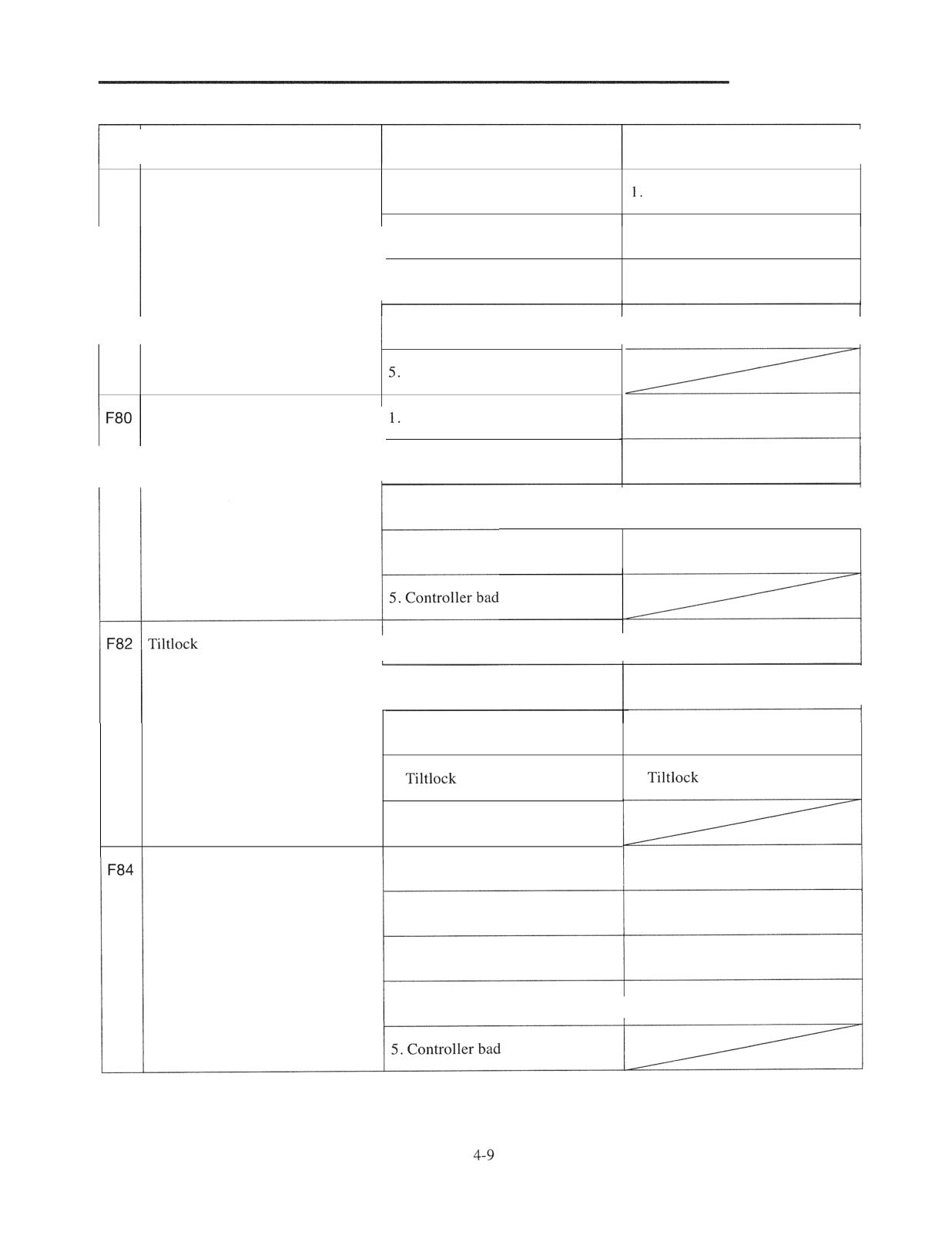
CONTROLLERS
Err
Description
Probable cause
Check point
code
F79
Unload sol leak
I. Connector contact bad
Connector connection check
2. Diode bad
2. Diode connection check
3. Harness bad
3. Harness connection check
4. Unload sol bad
4. Unload sol connection check
I
Controller bad
Knob pos sol err
Connector contact bad
1. Connector connection check
2. Diode bad
2. Diode connection check
3. Harness bad
3. Harness connection check
4. Knob pos sol bad
4. Knob pos sol connection check
sol err
I.Connector contact bad
1. Connector connection check
--
2. Diode bad
2. Diode connection check
3. Harness bad
3. Harness connection check
4.
sol bad
4.
sol connection check
5. Controller bad
Knob pos sol leak
1. Connector contact bad
1. Connector connection check
2. Diode bad
2. Diode connection check
3. Harness bad
3. Harness connection check
4. Knob pos sol bad
4. Knob pos sol connection check
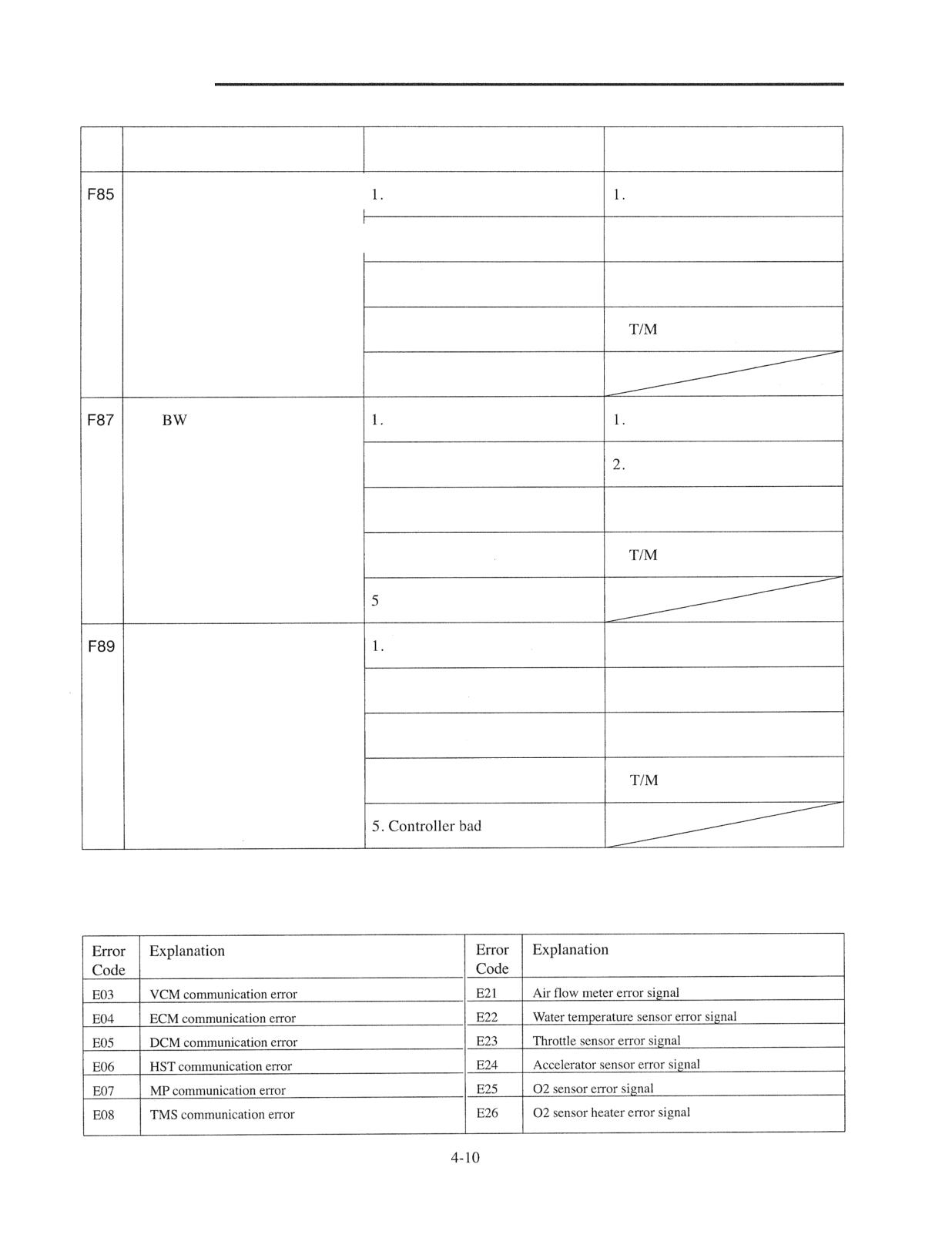
CONTROLLERS
Err
Description
Probable cause
Check point
code
TIM FW sol err
Connector contact bad
Connector connection check
2. Diode bad
2. Diode connection check
3. Harness bad
3. Harness connection check
4. TIM FW sol bad
4.
FW sol connection check
5.Controller bad
TIM
sol err
Connector contact bad
Connector connection check
2.
Diode bad
Diode connection check
3. Harness bad
3. Harness connection check
4.
TIM BW sol bad
4.
BW sol connection check
. Controller bad
TIM sol leak
Connector contact bad
1. Connector connection check
2. Diode bad
2. Diode connection check
3. Harness bad
3. Harness connection check
4. TIM sol bad
4.
sol connection check
Error Codes and Explanation
Contact your Cat lift truck dealer when the error code is displayed.
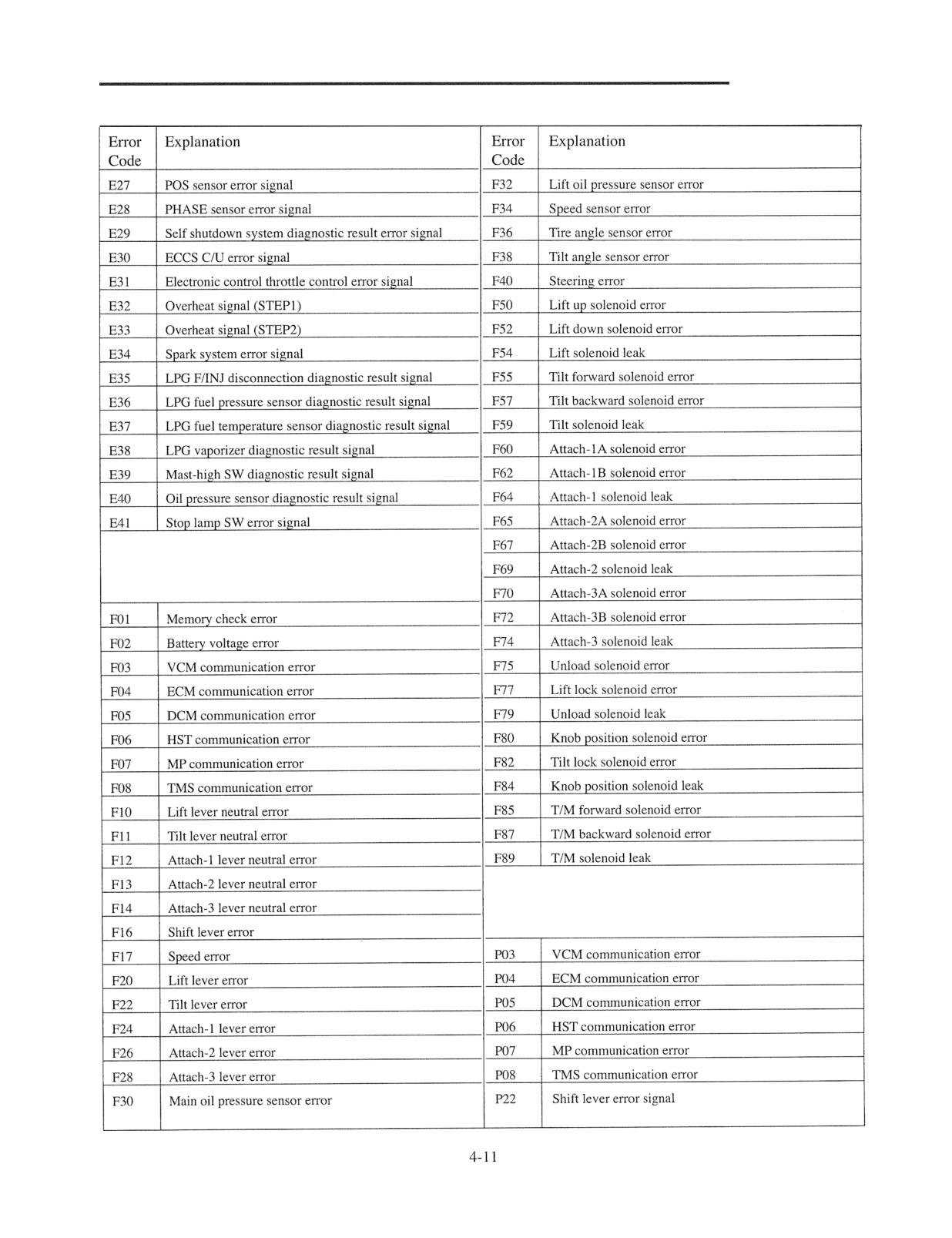
CONTROLLERS
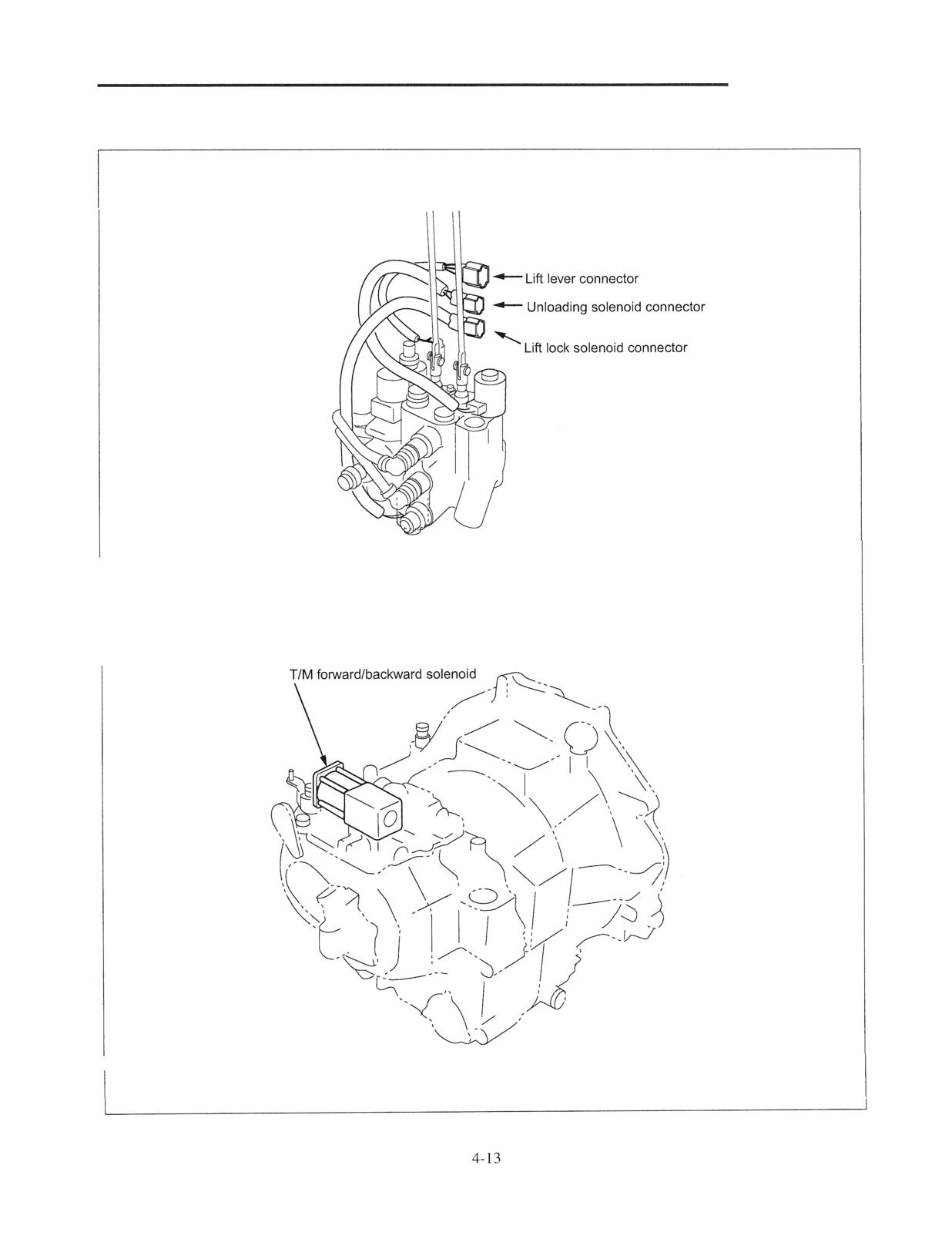
CONTROLLERS
Control valve
210116
Transmission
210117
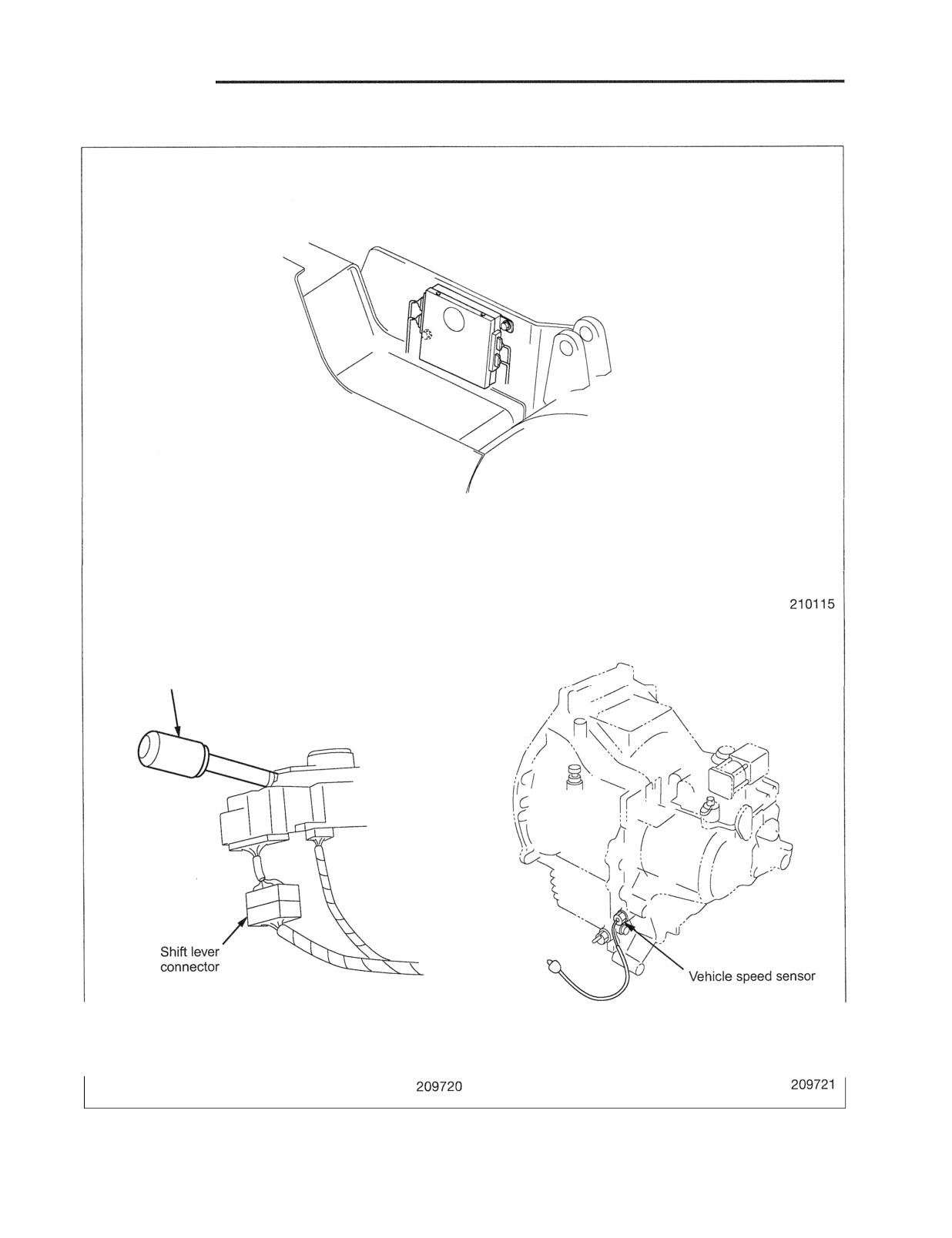
CONTROLLERS
Locations of Sensors and Switches
VCM
(Body Right Side)
Shift lever
Shift lever
(for Powershift Truck)
Transmission
(Right side)
CONTROLLERS
Others (Option)
I
Sensor
I
Location
I
Tilt Angle Sensor and Connector
Tilt Cylinder Pin
(For tilt automatic leveling option)
Tilt Lock Solenoid and Connector
Between Control Valve and Tilt Cylinder
(For tilt automatic leveling option)
Lift Pressure Sensor and Connector
Between Control Valve and Lift Cylinder
POWER TRA
and installation
5
Removal of Engine and Transmission Assembly
(for Gasoline-engine Trucks)
5 -
1
Overhead Guard, Covers, Air Cleaner and Other Components
5 -
1
Controls
5-
2
LPG system (Dual Fuel Gasoline and LPG Model)
5 -
3
Radiator and Pipes
5 -
4
Engine and Transmission Assembly
5 -
5
Installation
5 -
Removal of Engine and Transmission Assembly
(for Diesel-engine Trucks)
5 -
7
Overhead Guard, Covers, Air Cleaner and Other Components
5 -
7
Controls
5 -
8
Radiator and Pipes
5 -
Engine and Transmission Assembly
5 - 10
POWER TRAIN
and Installation
Removal of Engine and Transmission Assembly (for Gasoline-engine Trucks)
The engine and transmission are installed as an
assembled unit. The engine may be removed
independently of the transmission, but the transmission
can only be removed together with the engine.
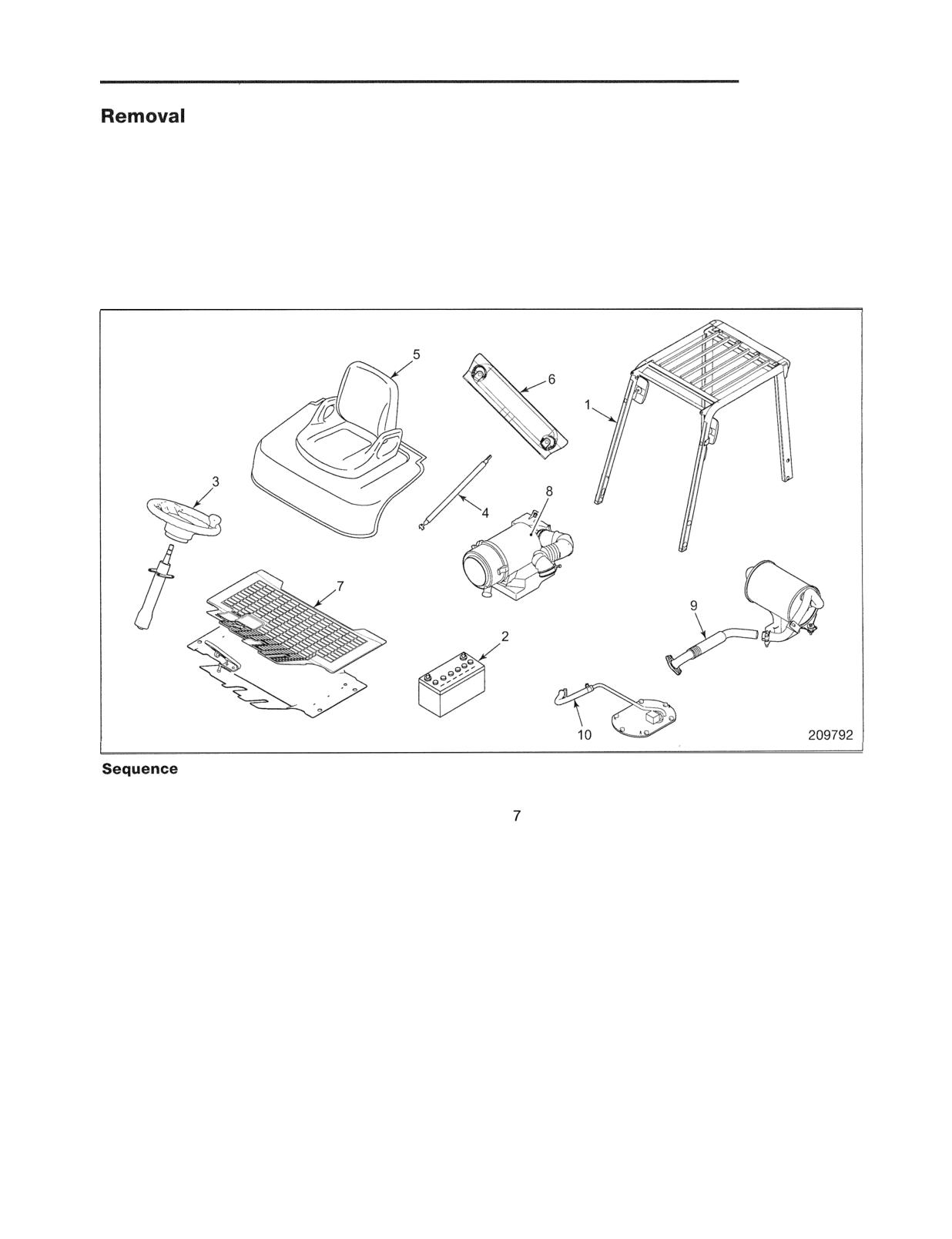
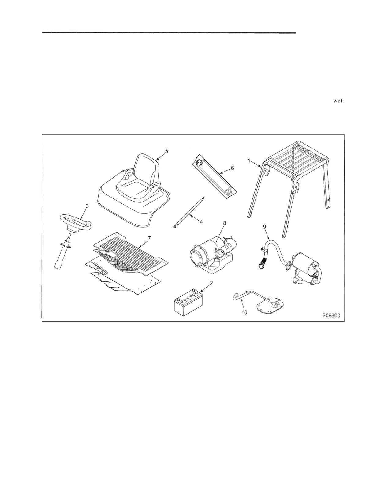
Overhead Guard, Covers, Air Cleaner and Other Components
1 Overhead guard, Headlamps
6 Radiator cover
2 Batteries, Cables
Floor plate, Floor mat
3 Steering wheel
8 Air hose, Air cleaner
4 Gas springs
9 Exhaust pipe
5 Engine cover, Seat
10 Fuel hoses (without LPG engine models)
Suggestions for Removal
(1) When removing the batteries 2, be sure to
(4) Before removing the fuel hose 10, make sure to
disconnect the ground (negative) cable first.
close the cock on the fuel tank.
(2) Remove the floor plate and mat 7 together with the
(5) After disconnecting the harness connectors from
accelerator pedal after disconnecting the pedal from
the sockets and terminals on the engine and
the linkage rod.
transmission they should be attached to the main
harness, in order to avoid damaging them.
(3) Disconnect the exhaust pipe 9 from the engine.
POWER TRAIN
Controls
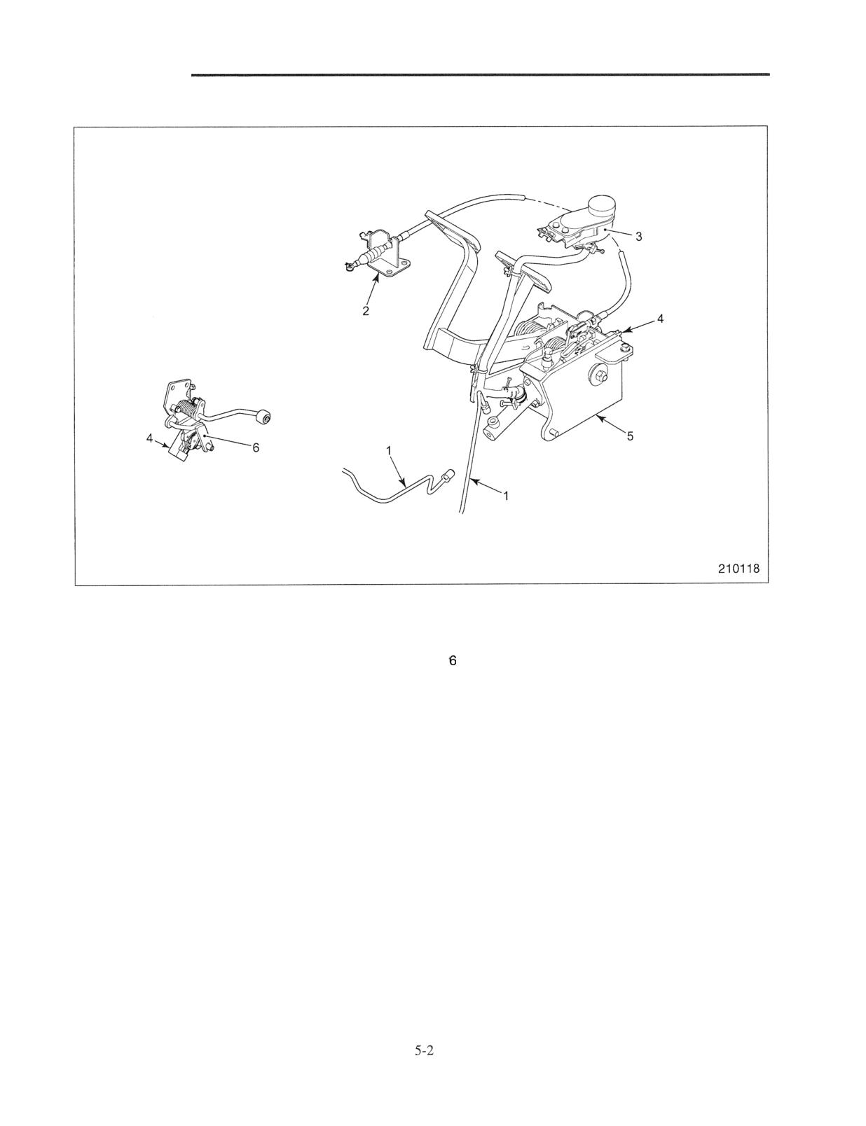
Sequence
I Brake pipe
4 Connector (Throttle, Stop lamp switches)
2 Inching cable, Clevis pin, Washer, Snap pin
5 Pedal assembly
3 Oil tank
Accelerator bracket
Suggestion for Removal
To remove the inching cable 2, disconnect the inching
pedal end and the transmission end and loosen the lock
nuts.
Installation
Follow the removal sequence in reverse.
POWER
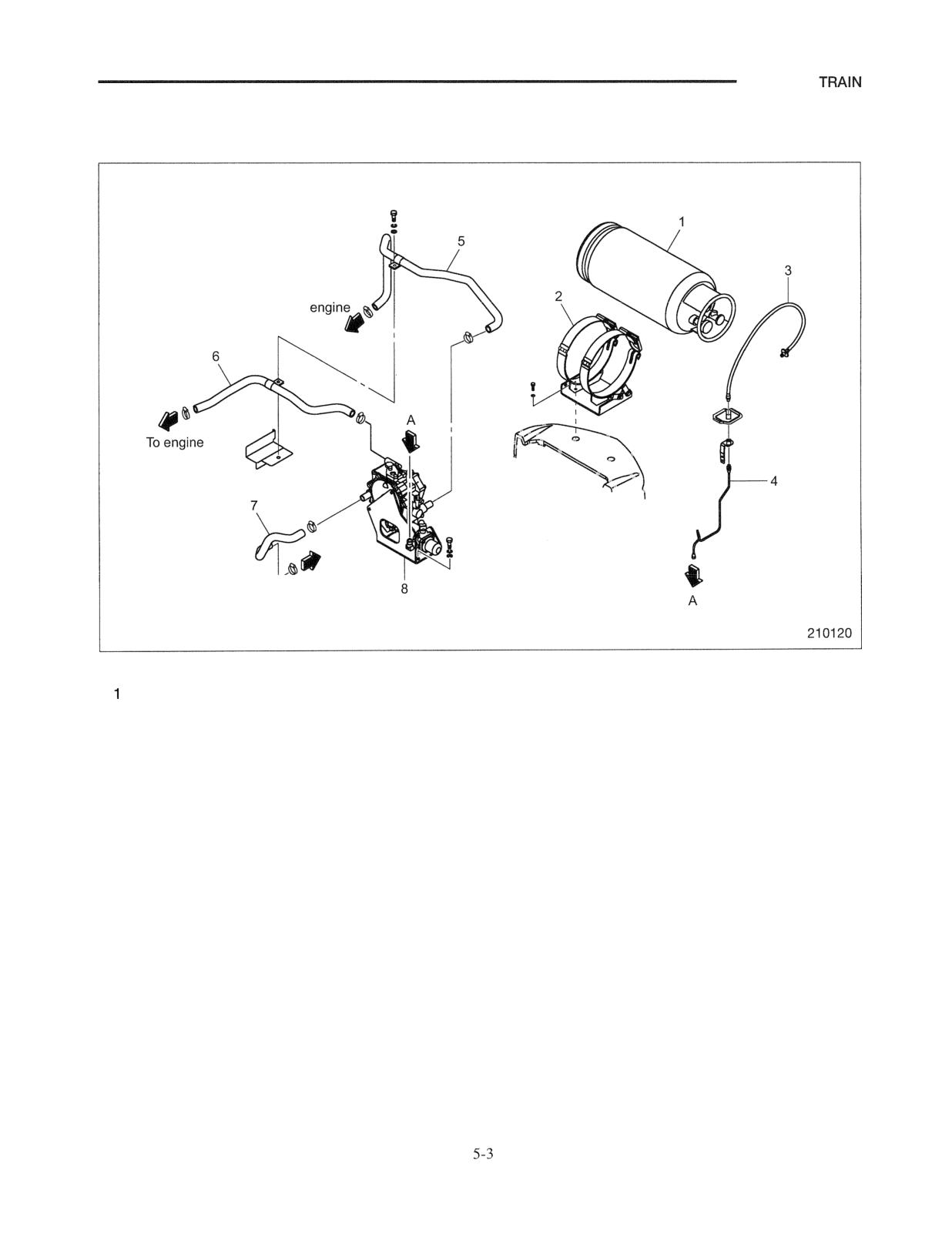
LPG system (Dual Fuel Gasoline and LPG Model)
Disassembly
To
v
To engine
Sequence
LPG tank
5 Water hose
2 Tank bracket
6 LPG hose
3 LPG hose
7 Water hose
4 LPG pipe
8 Vaporizer assembly
Start by:
(a) Drain the coolant from the engine by removing the
drain plug.
(b) Drain the coolant from the radiator by loosening the
cock at the bottom of the radiator.
POWER TRAIN
Radiator and Pipes
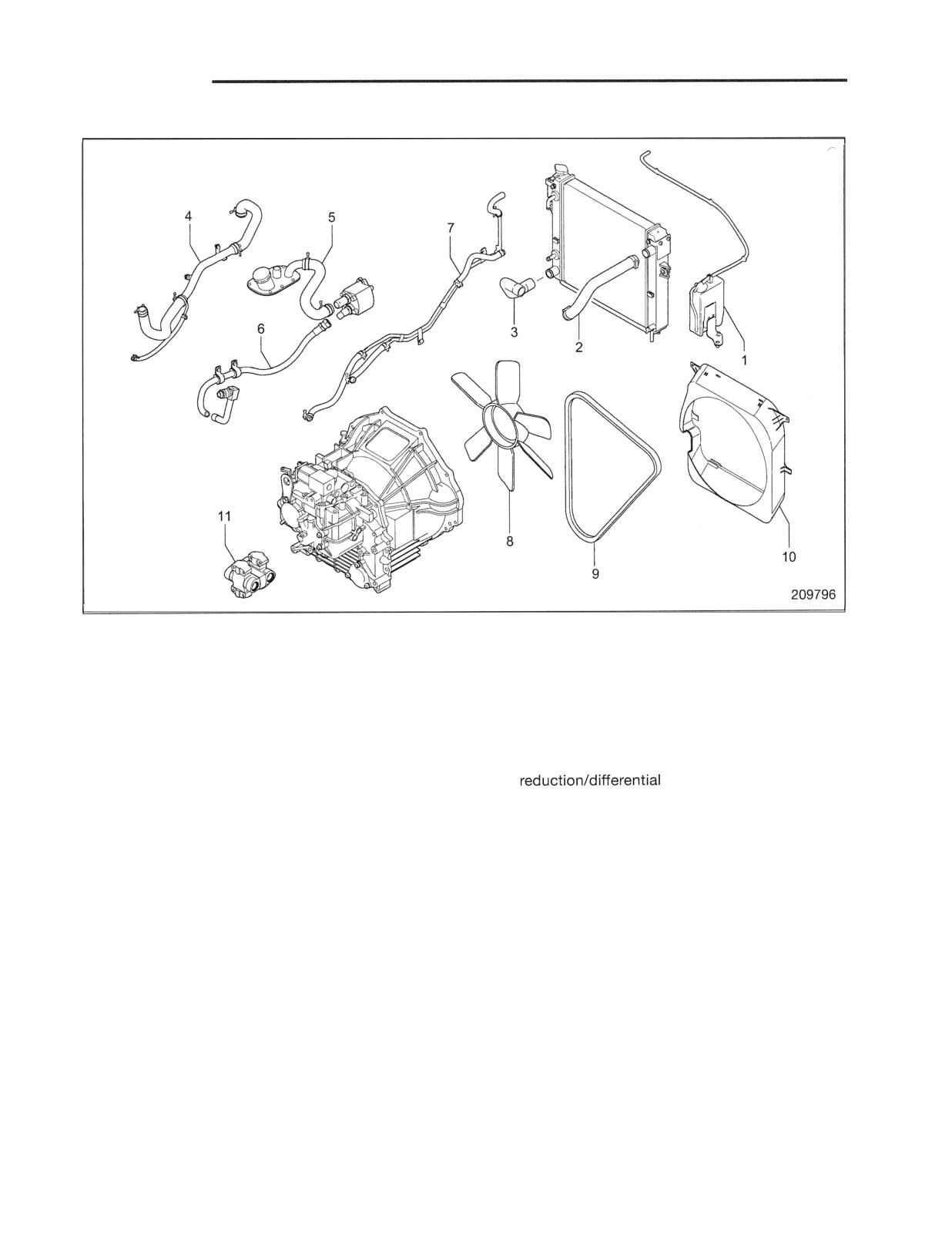
Sequence
1 Reserve tank
7 Cooler hose (between radiator and powershift
2 Hose (upper)
transmission)
3 Hose (lower)
8 Cooling fan
4 Hose (between hydraulic tank and control
9 Fan belt
valve)
10 Fan guard
5 Hose (between hydraulic tank and oil pump)
11 Universal joint (between transmission and
6 Hose (between oil pump and steering control
gears)
valve)
Start by:
Installation
(a) Drain the coolant from the engine by removing the
Follow the removal sequence in reverse.
drain plug (note that the position of the drain plug
differs by engine type).
(b) Drain the coolant from the radiator by loosening
the cock at the bottom of the radiator.
Suggestion for Removal
Disconnect the cooler hose 7 from the transmission side
and temporarily attach it to the right side of the frame.
POWER
Engine and Transmission Assembly
I
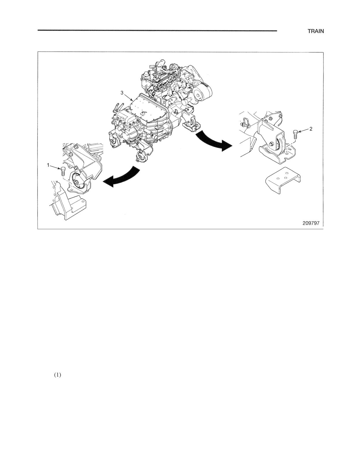
Sequence
1 Transmission mounting bolt
3 Engine and transmission assembly
2 Engine mounting bolt
Start by:
(a) Lifting the engine and transmission assembly with a
hoist and slings.
Suggestions for Removal
(1) Lift the engine and transmission assembly just the
amount necessary to remove the load on the mounting
cushion before removing the mounting bolts 1 and 2.
Remove the engine support mounting bolts.
(2) Slowly lift the engine and transmission assembly 3 out
by moving it backwards while maintaining its balance.
Note:
With the engine and transmission suspended,
drain the transmission oil and clutch oil.
(2) There is only one drain plug in the powershift
transmission.
POWER TRAIN
Follow the removal sequence in reverse.
Suggestions for Installation
(1) Engine and transmission assembly
(a) Slowly lift the assembly.
(b) On the transmission side, tighten the bolts of the
left and right mounts after aligning them with the
holes in the differential case.
(c) On the engine side, tighten the bolts of the left and
right engine supports after aligning them with the
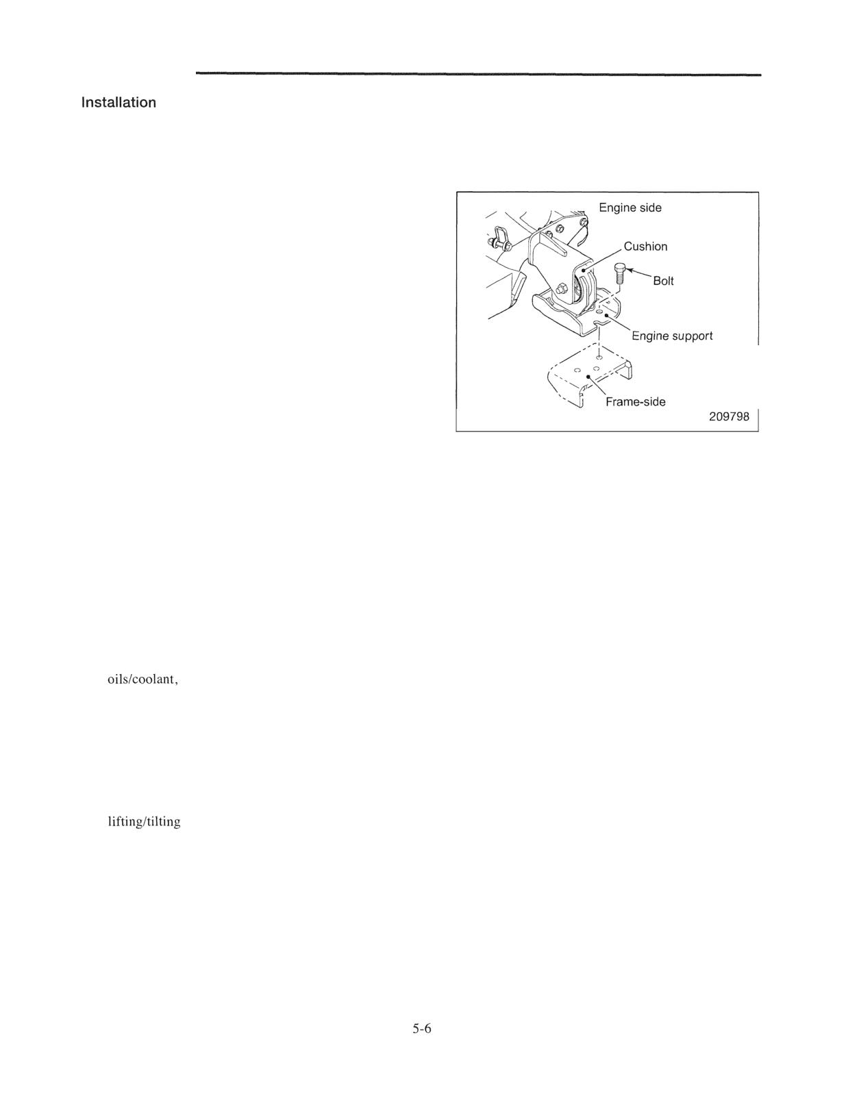
holes in the engine mounts.
engine mount
(2) For powershift transmission trucks, check that the
clutch valve plunger is pushed out completely when the
cable is connected between the inching pedal and the
transmission.
(3) Bleed the air out of the brake fluid circuit after
connecting the brake pipe.
(4) When installing the exhaust pipe, use a new gasket.
(5) Connect the ground (negative) cable to the battery only
after making sure that all wiring is connected properly.
(6) Refill the engine, radiator, and transmission with
and check for leakage. Unless otherwise
specified, use soft water (tap water) mixed with
antifreeze at a concentration of 35%.
(7) Bleed the air out of the fuel circuit of the engine.
(8) After checking the parts, start the engine and check
that the clutch booster functions properly (wet-type
clutch transmission trucks only). Operate the mast
and steering, and check the hydraulic oil
level. Also recheck the engine oil, coolant and
transmission oil levels.
POWER TRAIN
Removal of Engine and Transmission Assembly (for Diesel-engine Trucks)
The engine and transmission are installed as an
Note: There are two types of transmission, namely the
assembled unit. The engine may be removed
torque converter drive type (powershift
independently of the transmission, but the transmission
transmission) and the direct drive type (manual
can only be removed together with the engine.
transmission). Removal procedures vary for
direct drive type transmissions according to
whether they have a dry-type clutch or a
type clutch.
Overhead Guard, Covers, Air Cleaner and Other Components
I
Sequence
1 Overhead guard, Headlamps
6 Radiator cover
2 Batteries, Cables
7 Floor plate, Floor mat
3 Steering wheel
8 Air hose, Air cleaner
4 Gas springs
9 Exhaust pipe
5 Engine cover, Seat
10 Fuel hose
Suggestions for Removal
(1) When removing the batteries 2, be sure to
(4) Before removing the fuel hose 10, make sure to
disconnect the ground (negative) cable first.
close the cock on the fuel tank.
(2) Remove the floor plate and mat 7 together with the
(5) After disconnecting the harness connectors from
accelerator pedal after disconnecting the pedal from
the sockets and terminals on the engine and
the linkage rod.
transmission they should be attached to the main
harness, in order to avoid damaging them.
(3) Disconnect the exhaust pipe 9 from the engine.
POWER TRAIN
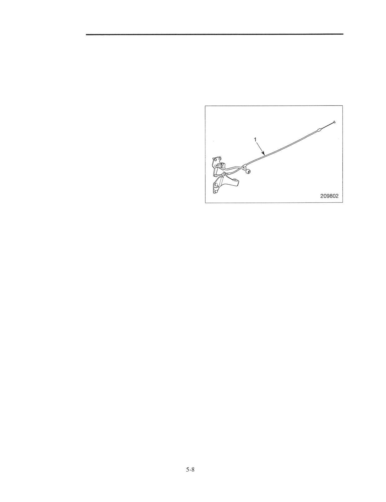
Controls
This section describes only removal and installation
procedures specific to diesel-engine trucks. Follow the
instructions for the gasoline-engine trucks in the preceding
sections for the common procedures.
Sequence
1 Throttle cable
POWER TRAIN
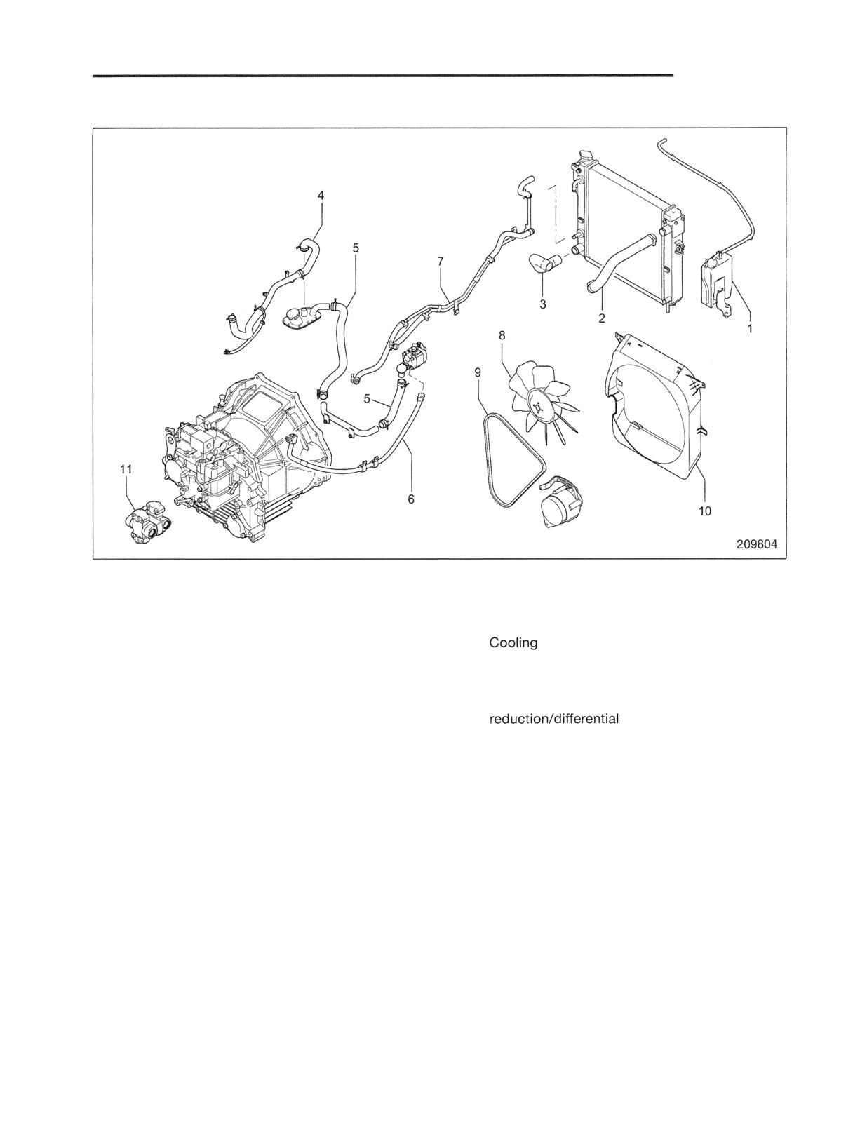
Radiator and Pipes
Sequence
1 Reserve tank
7 Cooler hose (between radiator and powershift
2 Hose (upper)
transmission)
3 Hose (lower)
8
fan
4 Hose (between hydraulic tank and control
9 Fan belt
valve)
10 Fan guard
5 Hose (between hydraulic tank and oil pump)
11 Universal joint (between transmission and
6 Hose (between oil pump and steering control
gears)
valve)
Start by:
Installation
(a) Drain the coolant from the engine by removing the
Follow the removal sequence in reverse.
drain plug (note that the position of the drain plug
differs by engine type).
(b) Drain the coolant from the radiator by loosening
the cock at the bottom of the radiator.
Suggestion for Removal
Disconnect the cooler hose 7 from the transmission side
and temporarily attach it to the right side of the frame.
POWER TRAIN
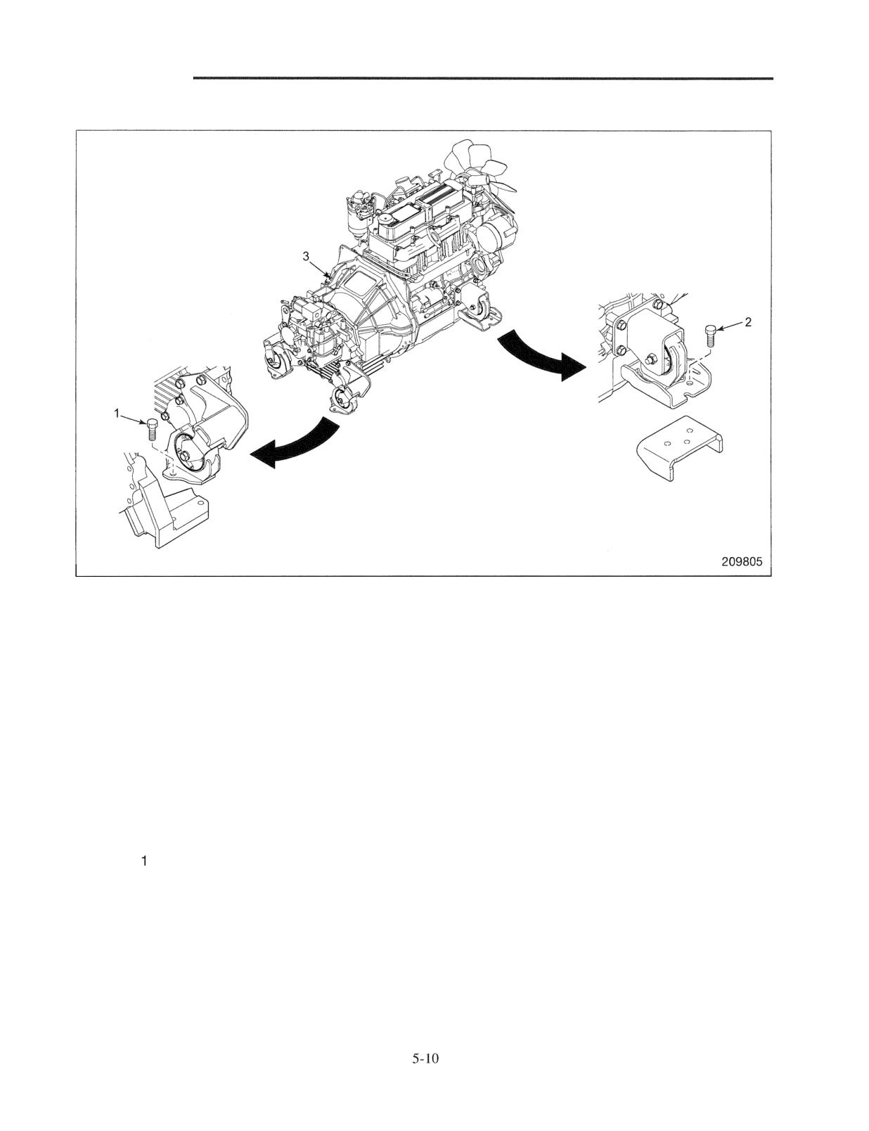
Engine and Transmission Assembly
Sequence
1 Transmission mounting bolt
3 Engine and transmission assembly
2 Engine mounting bolt
Start by:
Installation
(a) Lifting the engine and transmission assembly with
This section describes only removal and installation
a hoist and slings.
procedures specific to diesel-engine trucks. Follow the
instructions for the gasoline-engine trucks in the
preceding sections for the common procedures.
Suggestions for Removal
(1) Lift the engine and transmission assembly just the
Suggestion for Installation (those not shared with
amount necessary to remove the load on the
gasoline-engine trucks)
mounting cushion before removing the mounting
bolts
and 2. Remove the engine support
Connect the accelerator pedal linkage on the floor plate
mounting bolts.
to the throttle cable. Check that the injection pump
lever at the full-open position when the accelerator
(2) Slowly lift the engine and transmission assembly 3
pedal is fully depressed.
out by moving it backwards while maintaining its
balance.
Note: Drain the powershift transmission oil with the
engine and transmission assembly suspended.
TRANSM
Structure and Function
6
1
Transmission
6.
1
Torque Converter
6
3
Control System of Powershift Transmission
6.
4
Hydraulic System Schematic of Powershift Transmission
6.
5
and Installation
6
6
Removal
6
6
6.
6
Disassembly and Reassembly
6
Transmission External Parts and Torque Converter Assembly
6
7
Transmission Housing and Output Gear
6.
8
Output Gear Assembly and
Shaft
6.
9
Oil Pump Assembly
6.
10
Reassembly
6.
11
Disassembly and Reassembly of Other Components
6.
14
Control Valve
6
14
Input Shaft Assembly
6.
20
Disassembly
6.
20
Reassembly
6.
24
Oil Pump Assembly
6
28
Disassembly
6.
28
Reassembly
................................................... 6. 29
Inspection and Adjustment
6 - 31
Oil Pressure Measurement
6
31
Clutch (Inching) Pedal Adjustment
6 - 34
Inching Valve Adjustment
6 - 36
Troubleshooting
6 -
6
41
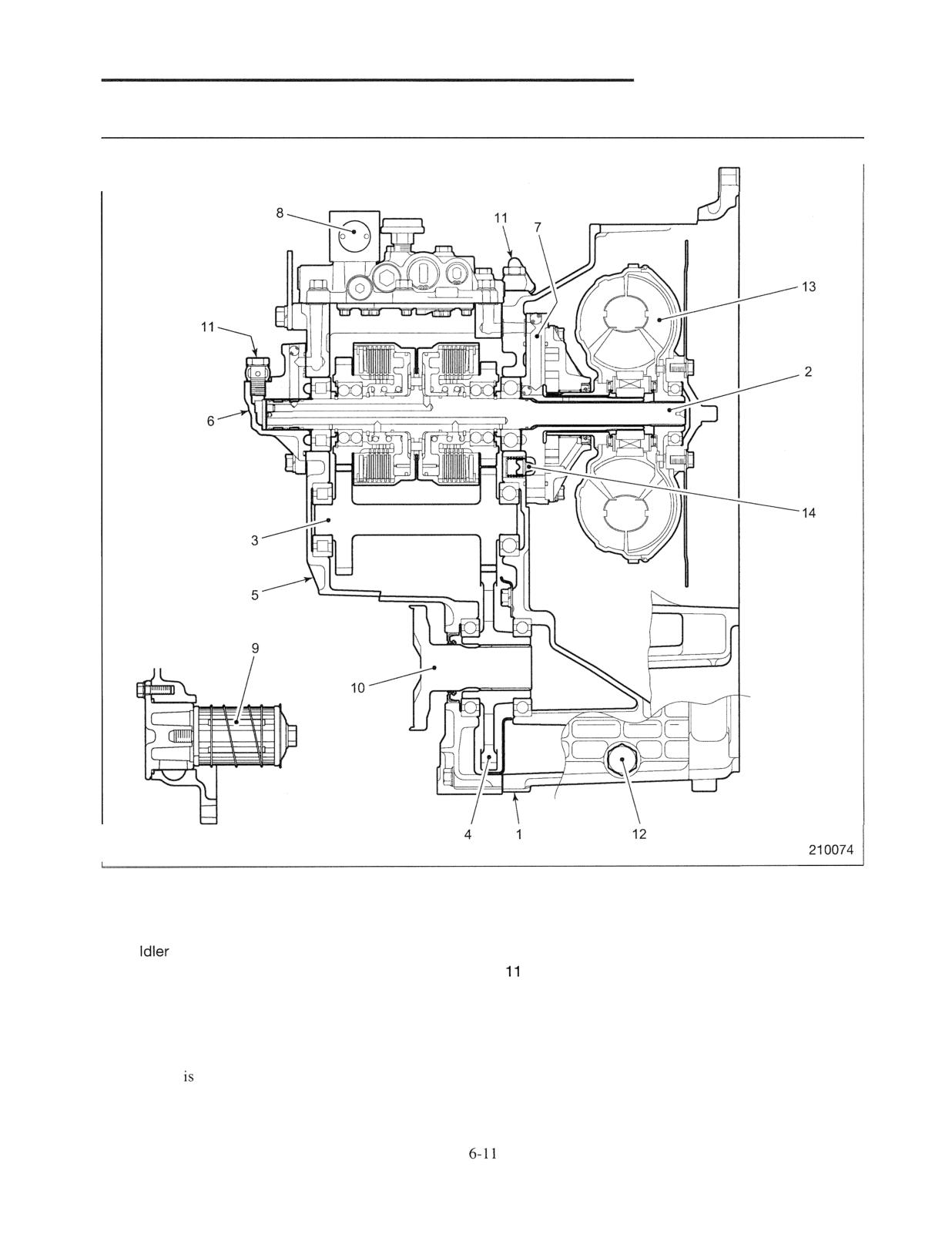
Structure and Function
Transmission
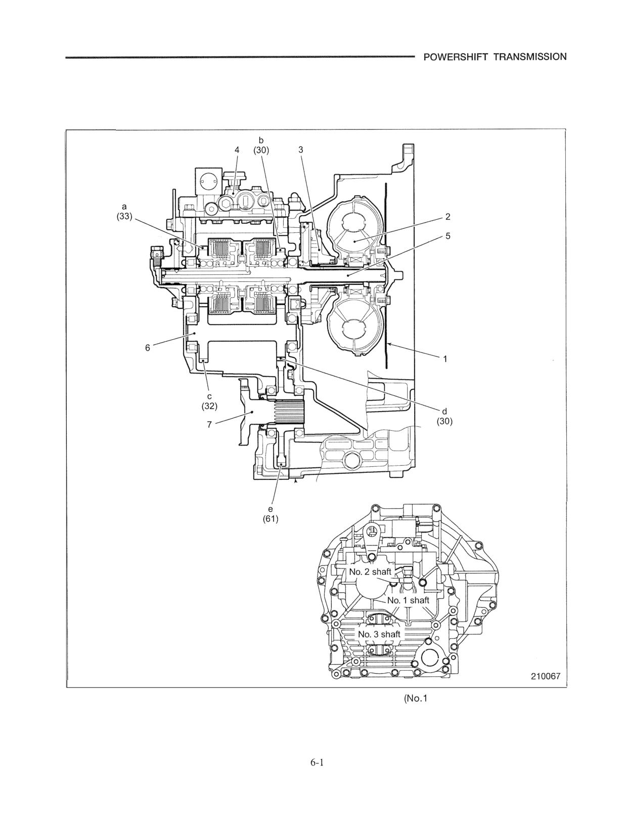
The figure in parentheses shows the number of
gear teeth.
1 Flexible plate
5 Input shaft
shaft)
2 Torque converter assembly
6 Idler shaft (No. 2 shaft)
3 Oil pump assembly
7 Output shaft (No. 3 shaft)
4 Control valve assembly
TRANSMISSION
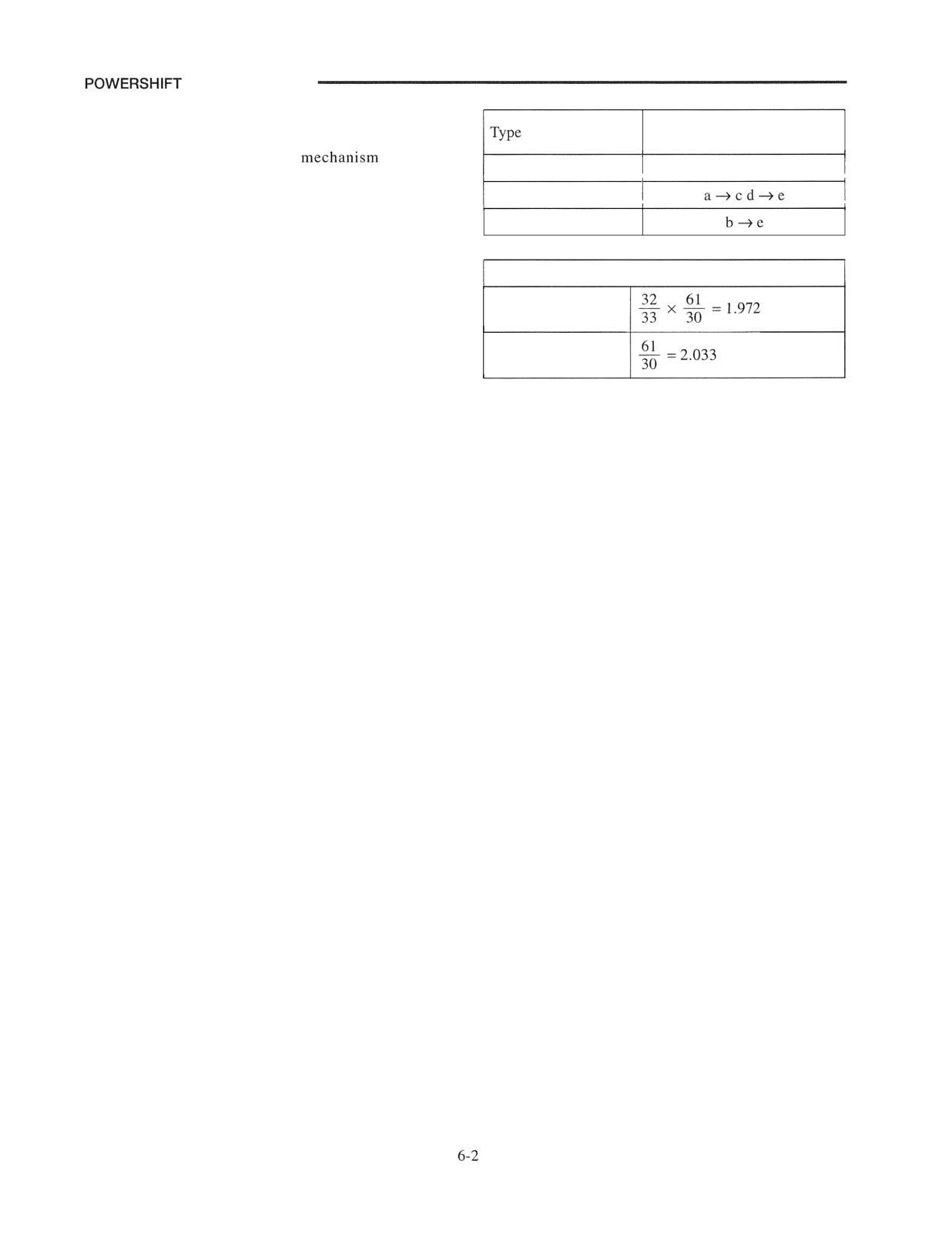
This transmission consists of one forward gear and one
Three-element, single-stage,
reverse gear. The forward-reverse changeover is
two-phase
accomplished by a powershift
that uses
Range
Power path
hydraulically controlled multiple-disc clutches. The
F (Forward)
same transmission parts, except for the torque
converter, clutch valve, output flange, and universal
R (Reverse)
joints, are used in all the 1 to 3.5 ton class trucks. The
transmission housing and torque converter housing can
Transmission reduction ratio
be separated from each other.
The torque converter shell is made of steel-plates
F (Forward)
welded in one body. For this reason, torque converter
parts can be replaced as an assembled unit only.
R (Reverse)
TRANSMISSION
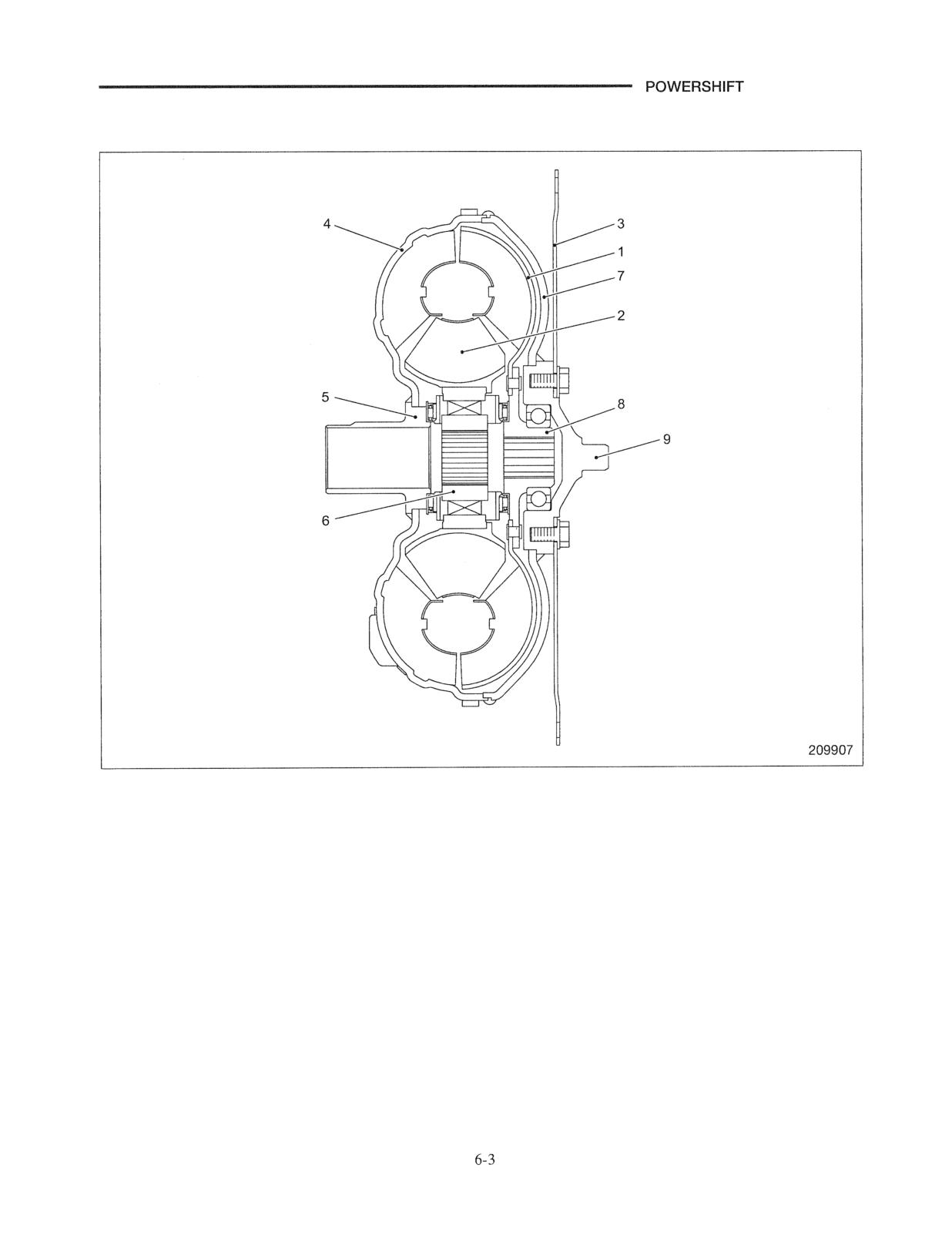
Torque Converter
1 Turbine runner
6 Clutch hub
2 Stator assembly
7 Drive cover
3 Flexible plate
8 Turbine boss
4 Pump impeller
9 Pilot boss
5 Pump boss
Note: Both gasoline-engine trucks and diesel-engine trucks
use the same type of torque converter.
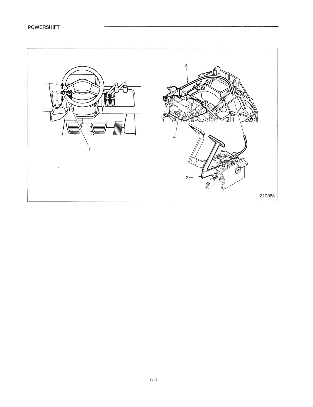
TRANSMISSION
Control System of Powershift Transmission
1 Forward-reverse shift lever
3 Cable (inching)
2 Clutch (inching) pedal
4 Control valve assembly
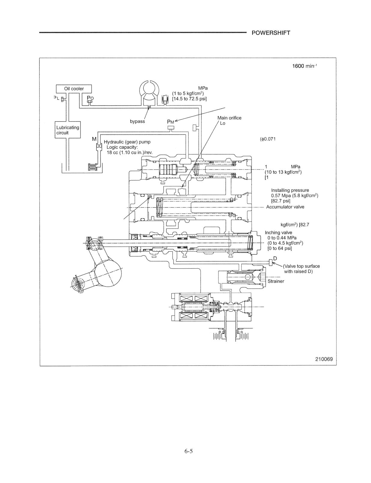
TRANSMISSION
Hydraulic System Schematic of Powershift Transmission
Engine speed at
(rpm)
Torque
converter
Torque converter inlet pressure relief valve
0.10 to 0.50
(Valve top surface with raised M )
Torque converter
w capacity TIM: $1.6 mm
$6.0 mm ($0.24 in.)
($0.063 in.)
High capacity TIM: $1.8 mm
in.)
Main regulator valve
OO to 1.30
Suction strainer
45 to 189 psi]
with magnet
100 mesh
Orifice bypass
Filling up completely
$1.7 mm ($0.067 in.)
pressure 0.57 Mpa
(5.8
psi]
Selector valve
CF
CR
Forward clutch
Reverse clutch
Removal and Installation
Removal
(1) Remove the engine and transmission as an assembly
from the truck.
Note: Removal and installation procedures for the engine
and transmission are covered in the "GROUP 5
POWER TRAIN." Drain oil out of the transmission
housing when removing the engine and
transmission.
(2) Remove the bolts securing the flexible plate through
the access hole in the torque converter housing.
(3) Separate the torque converter and transmission
assembly from the engine.
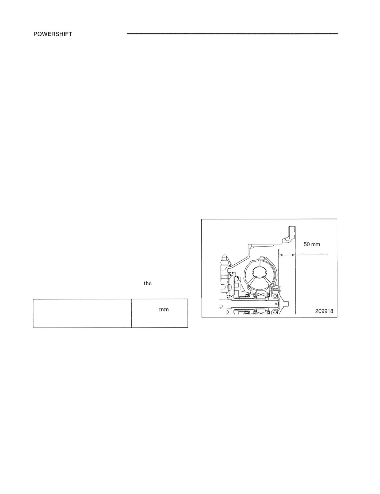
Couple the torque converter and transmission assembly
to the engine. To do this, push the torque converter
toward the transmission as far as it goes so that the
distance between the end surface of the torque
converter housing and the flywheel connecting surface
of the flexible plate is 50 mm (1.97 in.).
(2) Connect the flexible plate to the flywheel with the bolts
through the access hole in the torque converter
housing.
Note: Tighten the bolts evenly
progressively. Avoid
giving strain to the flexible plate.
TRANSMISSION
Disassembly and Reassembly
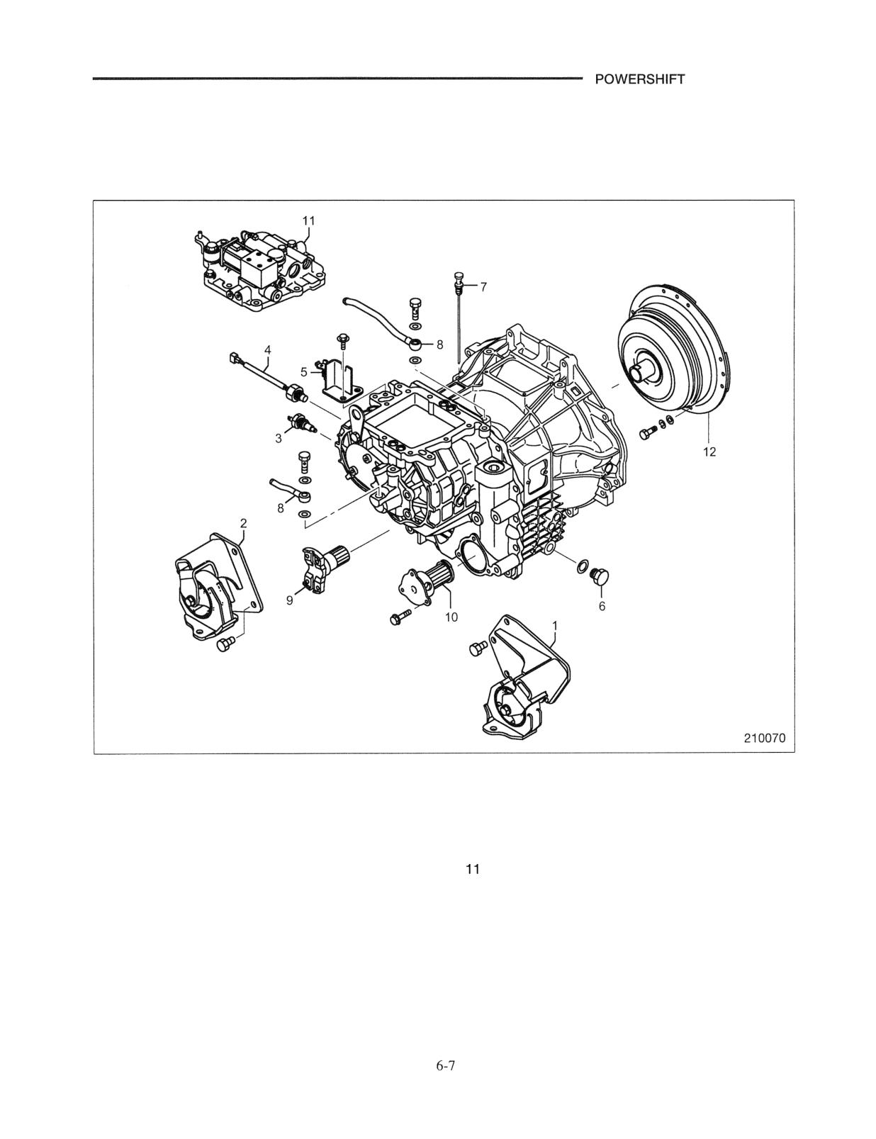
Transmission External Parts and Torque Converter Assembly
Disassembly
Sequence
1 Mount LH
7 Oil level gauge
2 Mount RH
8 Oil pipe, Eye joint, Gasket
3 Sending unit
9 Output flange
4 Pulse generator
10 Filter case, Magnet strainer
5 Cable bracket
Control valve, Gasket
6 Drain plug, Gasket
12 Torque converter assembly
TRANSMISSION
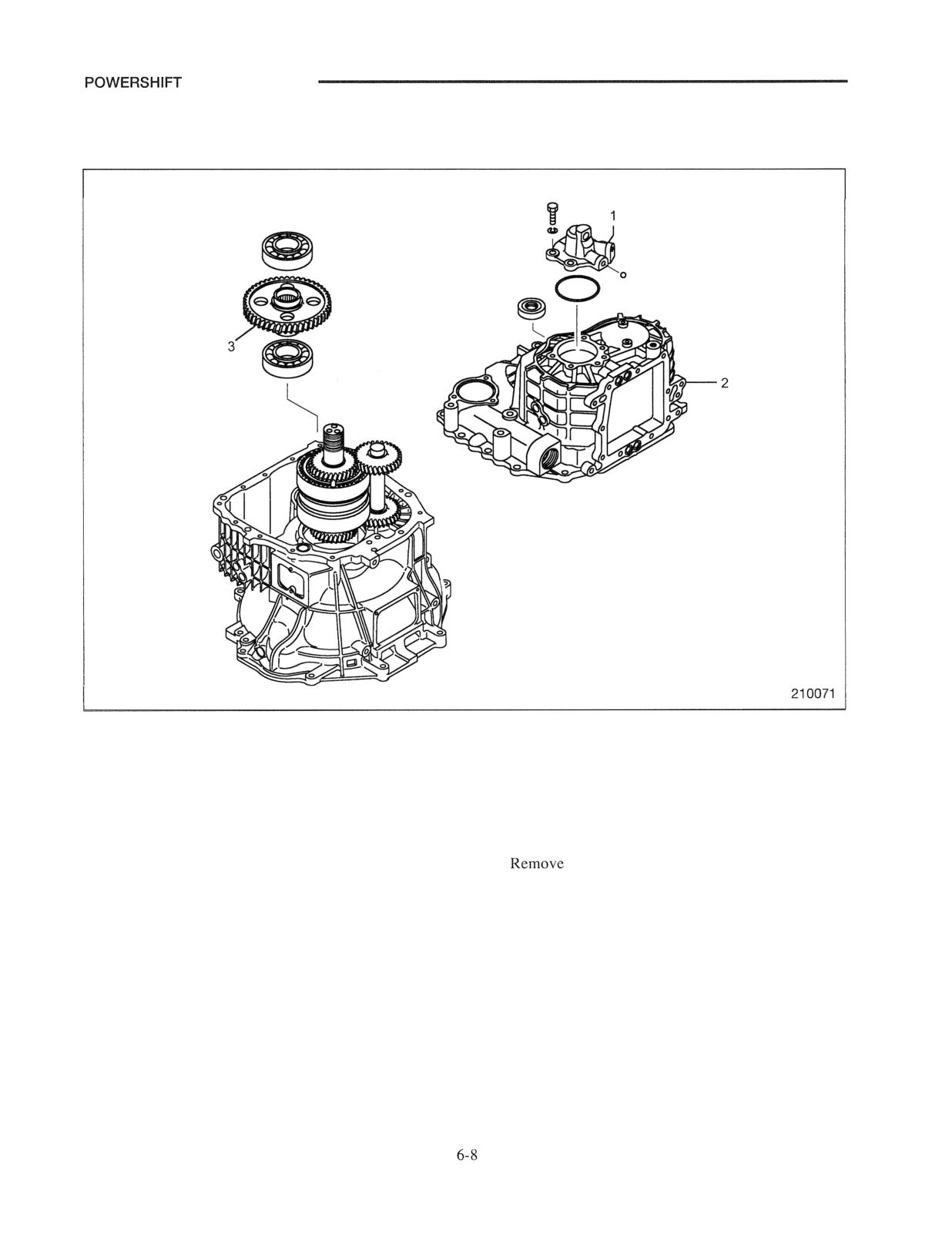
Transmission Housing and Output Gear
Disassembly
Sequence
1 Servo case assembly, O-ring, Steel ball
3 Output gear, Ball bearing
2 Transmission housing, Oil seal
Suggestions for Disassembly
(1) Place transmission assembly with the torque
(4)
the transmission housing and place it with
converter hosing end facing down. Remove the
its mating flange facing down.
bolts fastening the transmission housing to the
Note: (a) Do not remove any steel balls or sealing caps
torque converter housing.
that are fitted in the transmission housing
(2) Remove the servo case assembly. Lift the
and torque converter housing.
transmission housing using wire rope, lifting
(b) Inspect the oil seal in the transmission
hardware, and the holes for the hardware and the
housing. It must not be removed unless
mounting bolt holes on the housing.
defective.
(3) Keeping the wire ropes slightly taught, remove the
transmission housing by tapping the area around
the dowel-pin holes evenly with a plastic hammer.
TRANSMISSION
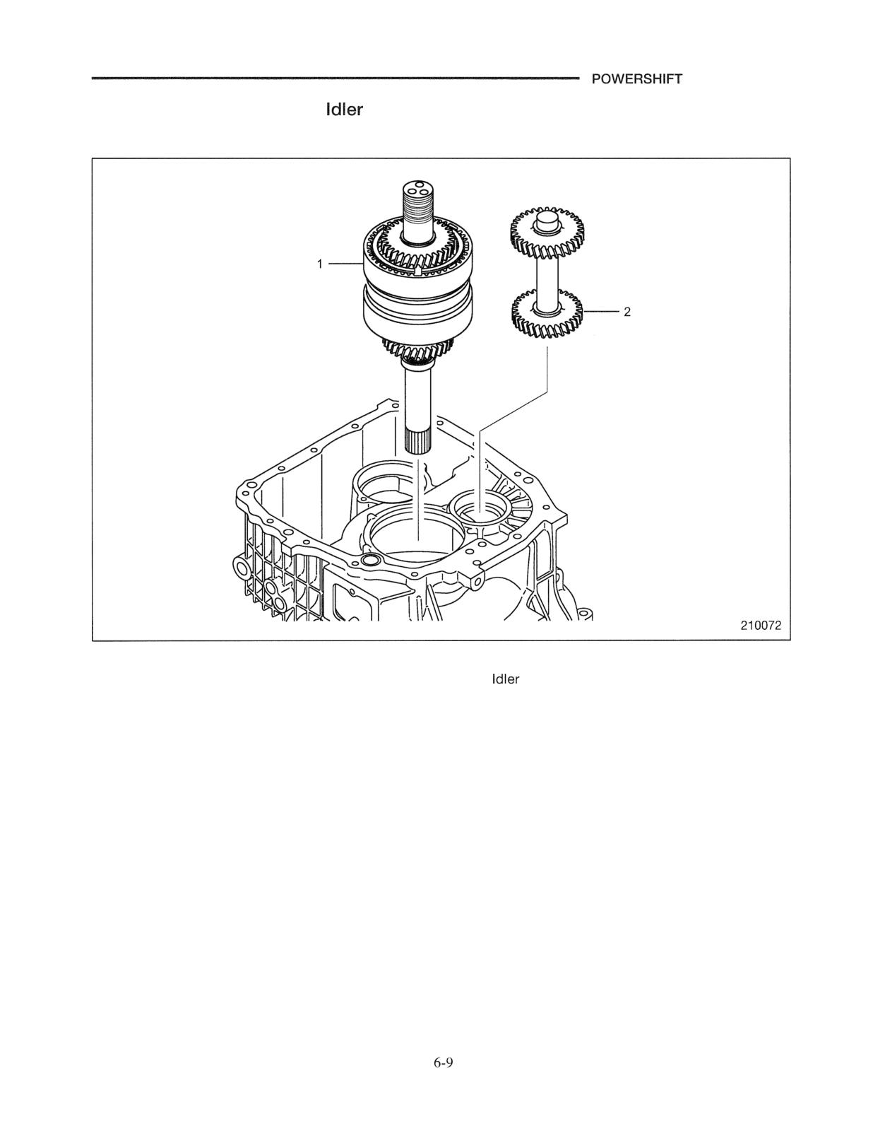
Output Gear Assembly and
Shaft
Disassembly
Sequence
1 Input gear assembly
2
shaft
Inspections after Disassembly
(1) Transmission housing
(a) Check seal lips the seal rings for wear.
(2) Magnet strainer
(a) Check for clogging and damage.
(3) Idler shaft
(a) Check the splines for wear and other damage.
(4) Output flange
(a) Check the splines for wear and other damage.
(b) Check the sliding surface to the oil seal for
damage.
TRANSMISSION
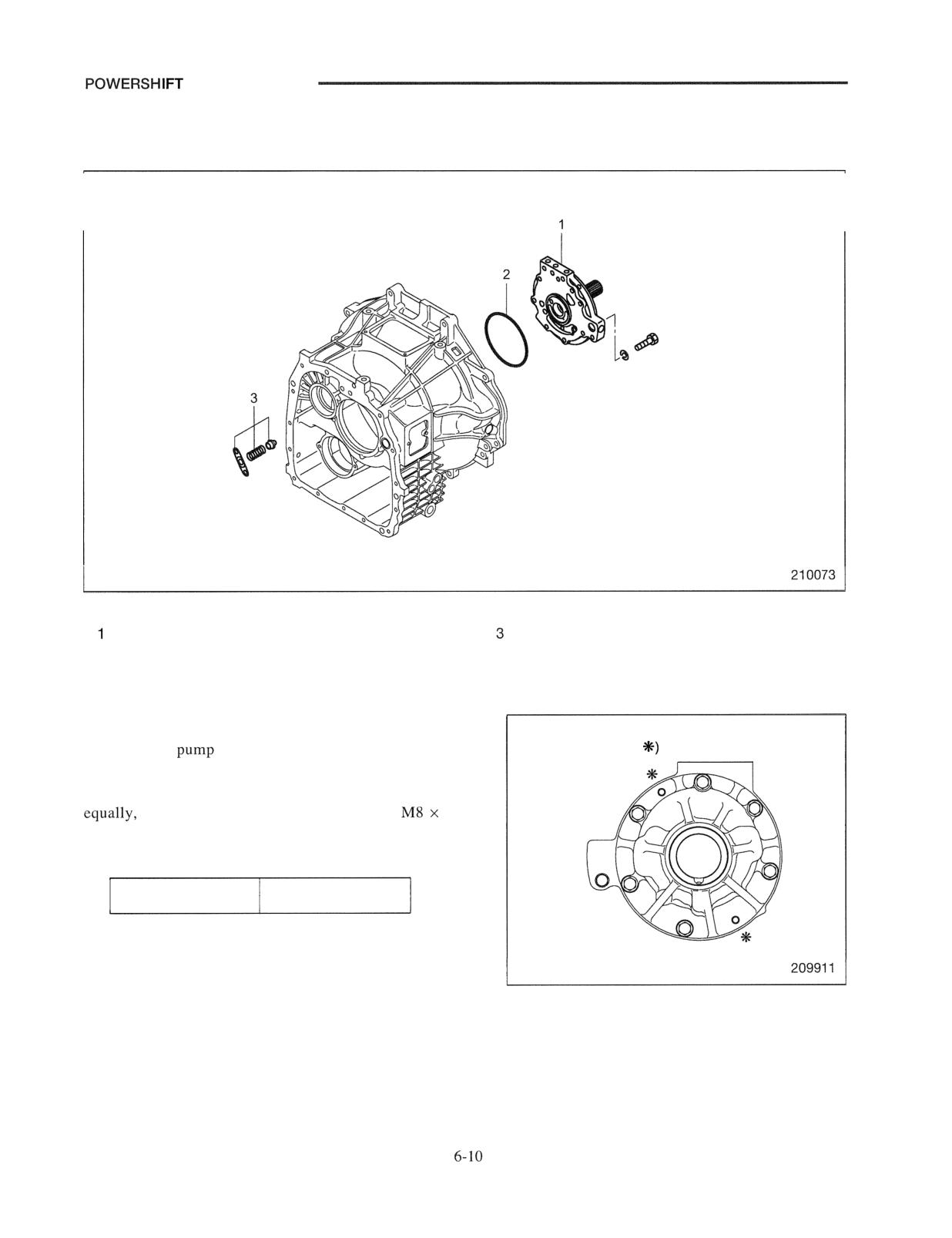
Oil Pump Assembly
Disassembly
Sequence
Oil pump assembly
Relief valve assembly
2 O-ring
Suggestion for Disassembly
(1) Removal of oil pump assembly
Lifting bolt holes
Unscrew the
mounting bolts and screw two bolts
(at locations marked
(special tool) into the M8 x 1.25 holes in the pump body to
remove the pump assembly. Be sure to tighten the bolts
or the threads will be damaged. Use
1.25
bolts having an effective thread length of 55 mm (2.2 in.)
Special tool needed
Bolt
67281-15400
POWERSHIFT TRANSMISSION
Reassembly
Sequence
1 Torque converter housing
8 Control valve assembly
2 Clutch pack assembly
9 Magnet strainer
3
gear
10 Output flange
4 Output gear
Oil pipe
5 Transmission housing
12 Drain plug, Oil temperature sensor, etc.
6 Servo case
13 Torque converter assembly
7 Oil pump assembly
14 Relief valve
Reassembly almost reverse of the disassembly sequence.
TRANSMISSION
Suggestions for Reassembly
(1) Applying grease
(a) Apply grease to the lips of the oil seals in the
transmission housing.
(2) Installing oil pump assembly
(a) Place the torque converter housing with its
weighted flange facing down.
(b) Install the relief valve and spring into the torque
converter housing.
(c) Apply grease to the O-ring and install it into the
torque converter housing. Then, install the oil
pump assembly.
(3) Installing transmission housing
(a) Reinstall the transmission housing while hoisting it
in the same procedure during disassembly. Pay
attention that the input shaft is not yet stable at the
center line.
(4) Installing torque converter
(a) Install the torque converter by aligning its splines
with the splines on the stator shaft and input shaft
of the transmission and the grooves in the oil pump
drive gear.
(1.97 in.)
(b) After the torque converter is installed, check the
distance between the end surface of the torque
converter housing and the flywheel fitting surface
of the flexible plate referring to
specification
below.
Distance between torque converter
50
housing end surface and flywheel
(1.97 in.)
fitting surface of flexible plate
(c) Secure the torque converter temporarily by tying
part of the flexible plate to the torque converter
housing using suitable wires until the assembly is
fixed to the engine.
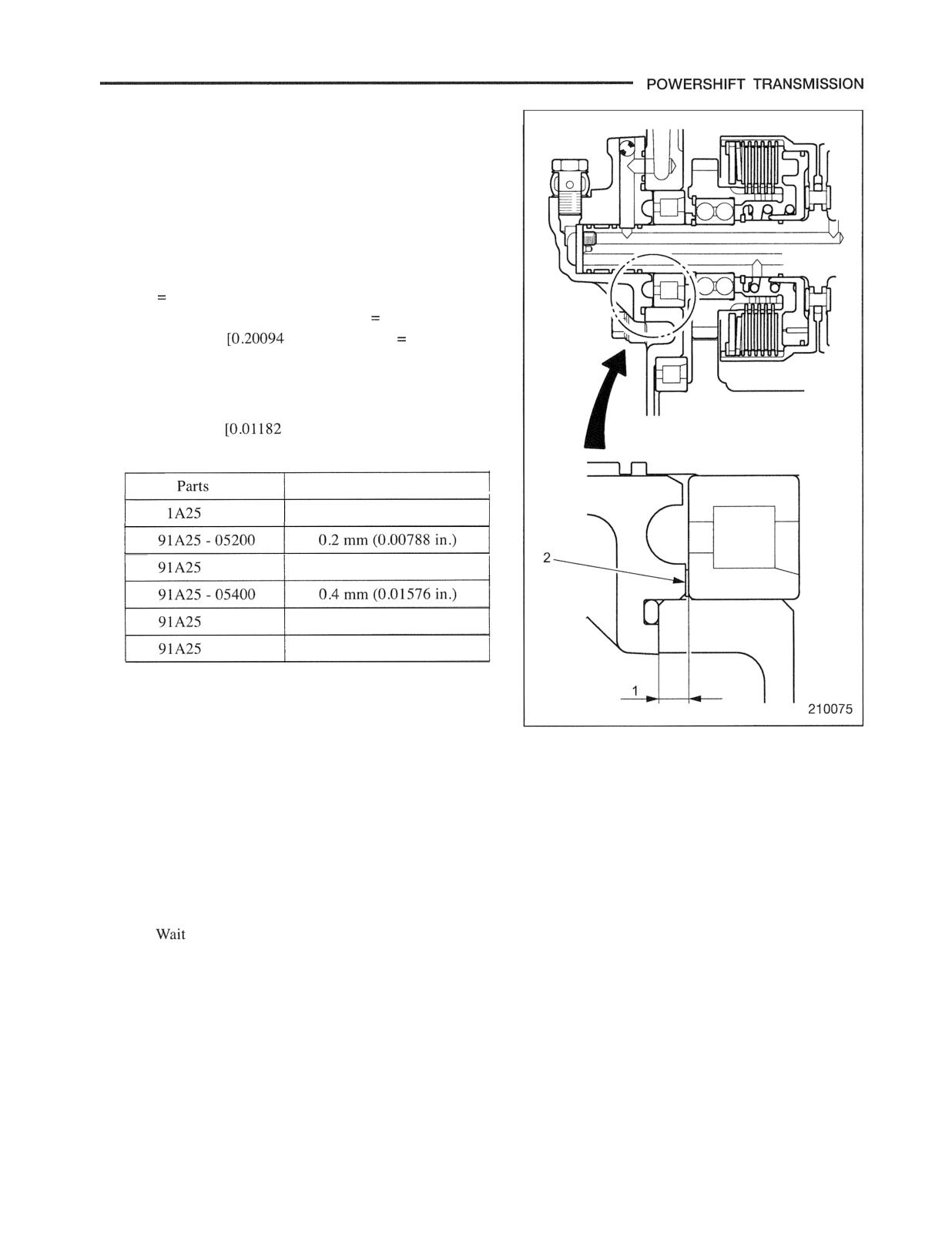
(5) Shim adjustment
(a) Thrust the clutch pack, the input shaft and the
support bearing toward the torque converter and
measure the concave dimension between the
contact surface of the servo case and the outer edge
of bearing 1 .
(b) Calculate the shim 2 thickness required as follows:
Concave dimension 1 - 4.8 mm (0.18912 in .)
shim thickness.
Example; (5.1 mm - 4.8 mm
0.3 mm)
in. - 0.18912 in.
0.01182 in.]
(c) Insert the calculate shims 2 between the bearing
supporting clutch pack and servo case and
assemble servo case. (This clearance axially is 0.3
to 0.4 mm
to 0.01576 in.])
Shims
NO.
Thickness
9
- 05100
0.1 mm (0.00394 in.)
- 05300
0.3 mm (0.01182 in.)
- 05500
0.5 rnm (0.01970 in.)
- 05600
0.6 mm (0.02364 in.)
(6) Refilling transmission with oil
(a) Refill the transmission with oil only after the
transmission is installed in the truck and the engine
is ready to be started.
(b) Check the oil level using the level gauge.
(c) Start and run the engine at an idling speed for
about 3 minute and then stop the engine.
(d)
for about 30 second after stopping the engine,
and then start the checking procedure.
(e) The checking procedure must be completed within
5 minutes after the engine has stopped.
//////////////////////////////////////////