Cat Lift Trucks. For use with K21/K25 and S4S Engine Service Manuals (2007) - page 4
MAST AND FORKS
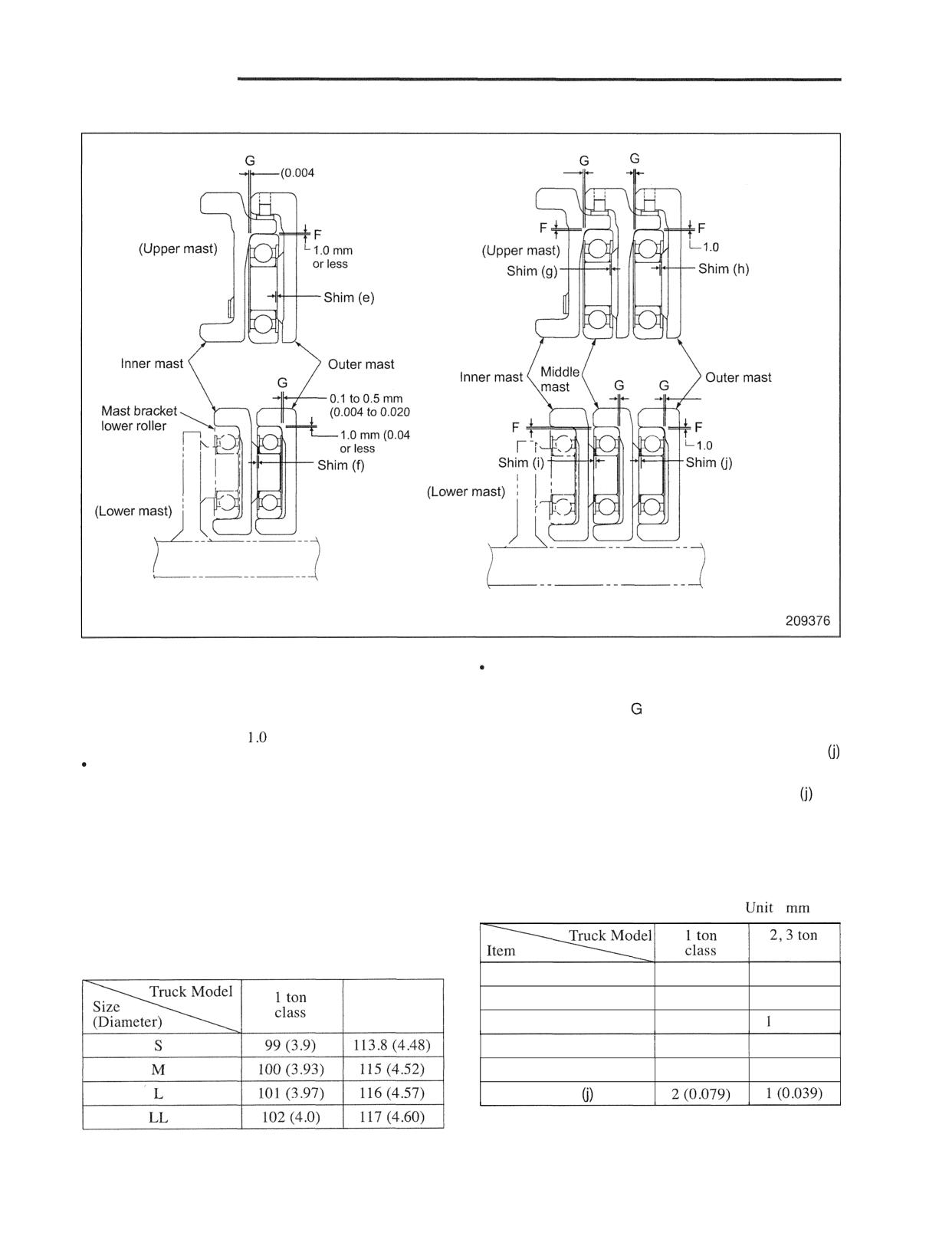
2. installing mast rollers (all mast models)
0.1 to 0.5 mm
0.1 to 0.5 rnm
to 0.020 in.)
(0.004 to 0.020 in.)
(0.04 in.)
rnrn (0.04 in.) or less
0.1 to 0.5 mm
in.)
(0.004 to 0.020 in.)
in.)
mm (0.04 in.) or less
Lift bracket
Lift bracket
Mast Roller for Simplex Mast
Mast Roller for Triplex Mast
and Duplex Mast
209375
Mast rollers are identical in shape and size with lift
Installation of mast rollers follows the same
bracket lower rollers.
procedures for the lift-bracket rollers.
Therefore:
(2) Measure clearance between the rollers and masts.
If the measured clearances exceed the standard
Clearance F should be
mm (0.04 in.) or less.
value, increase the thicknesses of shims (e) -
Clearance G should be 0.1 to 0.5 mm (0.004 to 0.020
under the roller seats as required.
in.).
Remarks: At the assembly plant, shims (e) -
are
(1) Measure clearance F between the rollers' rolling
usually adjusted to the values shown in the
contact surfaces and masts. If the measured
table below for the shipment.
clearances do not conform to the standard value,
replace with rollers of correct diameters listed in
the table below
:
(in.)
Note: For measuring procedures, refer to "Inspection
and Adjustment."
classes
Unit : mm (in.)
Shim (e)
2 (0.079)
1 (0.039)
2,3 ton
Shim (f)
2 (0.079)
1 (0.039)
classes
Shim (g)
1 (0.039)
(0.039)
Shim (h)
2 (0.079)
1 (0.039)
Shim (i)
2 (0.079)
1 (0.039)
Shim
MAST AND FORKS
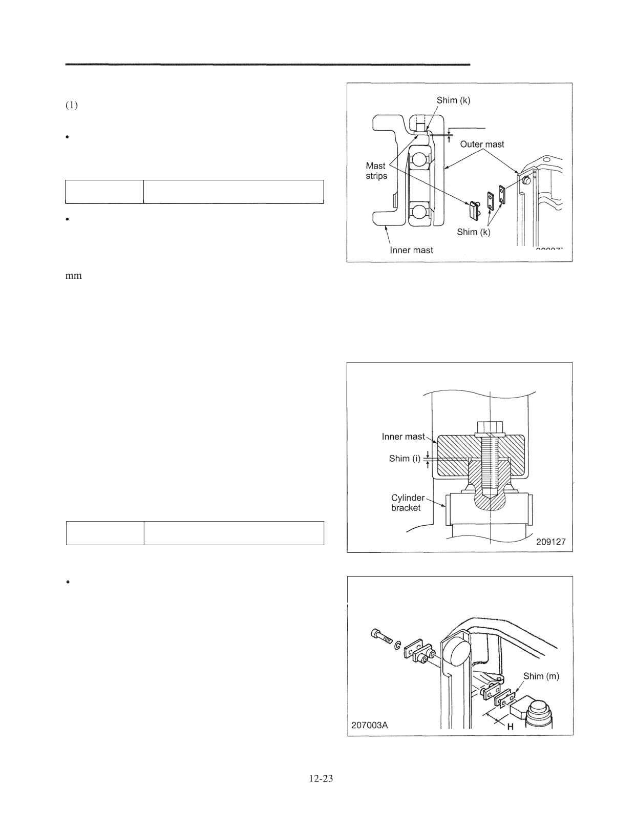
3. Installing mast strip (all mast models)
Simplex Mast
Measuring and adjusting clearance G2 between mast
strip and inner mast (all mast models)
0.1 to 0.5 mm
(0.004 to 0.020 in.)
Measurement
Make a clearance between the mast strip and inner mast.
Insert a thickness gage to measure the clearance G2.
Clearance G2
0.1 to 0.5 mm (0.004 to 0.020 in.)
Adjustment
If clearance G2 is excessive, add a proper amount of shims
under the mast strip. Check the smooth movement by
209377
moving slowly up and down the bracket. Usually, a 1.0
(0.04 in.) thick shim is used in a new truck.
4. Installing second lift cylinders (all mast models)
Note: Second lift cylinders have basically the same
structure across all mast models, except that some
details are different illustration.
(1) Install the cylinder brackets to the lift cylinders as
Simplex Mast
shown in the right illustration.
(2) Place the lift cylinders complete with the brackets
between the outer and inner masts.
(3) Install the lift cylinder rods to the inner mast as shown
in the illustration. If shims (I) are used, be sure to
reinstall them. Usually shims (I) are not used.
(4) With the cylinder rods fully retracted and the cylinders
set vertically, measure clearance H. Adjust the
clearance at 1.6 mm (0.063 in.) or less by adding or
removing shims (m).
Clearance H
1.6 mm (0.063 in.) or less
Adjustment
Simplex Mast
If clearance H is excessive, add shims (m). Normally on a
new truck, the second lift cylinders are not fitted with
shims (m). If the clearance is 3.2 mm (0.126 in.) or more,
make sure to include a 3.2 mm (0.126 in.) thick sheet in the
shim pack that is to be installed.
(5) After reassembly, perform an operation test to check if
the stroke of the left and right cylinders is the same.
For the checking procedure, refer to page 12-39.
MAST AND FORKS
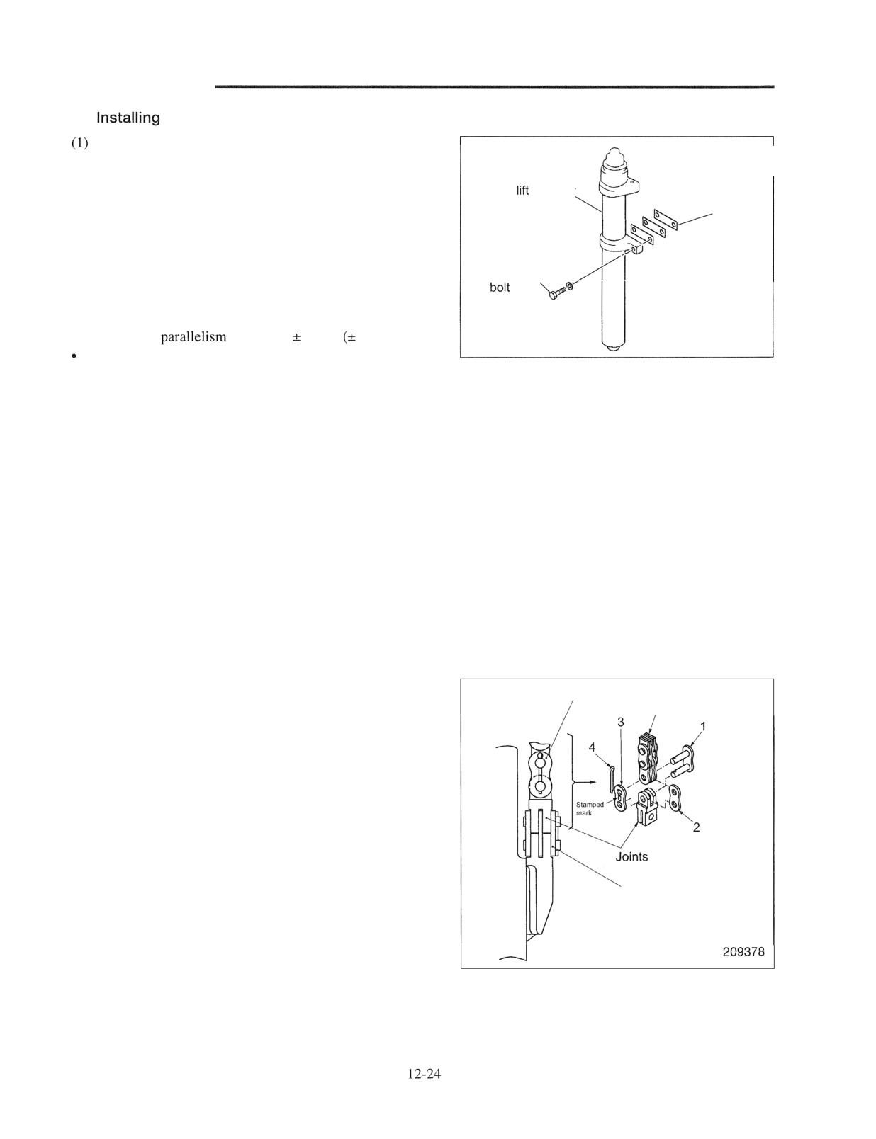
5.
first lift cylinders
With the masts set vertically and fully lowered,
temporarily install the first lift cylinder complete with
the original shims to the inner mast.
First
cylinder
(2) Set the first lift cylinders vertically, and measure the
Shims
clearance, if any, between the cylinder brackets and the
cylinder mounts on the inner mast. Remove any
clearance by adding shims.
Mounting
The perpendicularity of each cylinder in the lateral
direction can be checked by measuring the parallelism
between the cylinder and the side face of the inner mast.
Error of the
should be
1 mm
0.04 in.).
209126
The perpendicularity of each cylinder in the longitudinal
direction can be checked by visually inspecting for the
parallelism between the cylinder and the front face of the
inner mast. The cylinder slightly inclined to the rear is
acceptable. The cylinder should not be inclined forward
even slightly.
Each shim is 1 mm (0.04 in.) thick.
Remarks: At the manufacturing facility, a shim pack of 2.0
mm (0.08 in.) is usually inserted between the
cylinder bracket and the inner mast for the
shipment.
(3) After shimming is completed, install and tighten the
mounting bolts.
Note: Depending on the truck model, the direction in
which the mounting bolts are inserted may be
different from what is shown in the illustration.
6. Connecting chain (Simplex mast, 1 ton class)
Upper chain anchor kit
The lift chain is connected to the lift bracket by assembling
Chain
the upper chain anchor kit as shown in the right illustration.
Make sure that link plate 3 with a stamped mark is installed
on the outside of the chain.
Lower chain anchor kit
1 Link
2 Center plate (without stamped mark)
3 Link plate (with stamped mark)
4 Sprit pin
MAST
FORKS
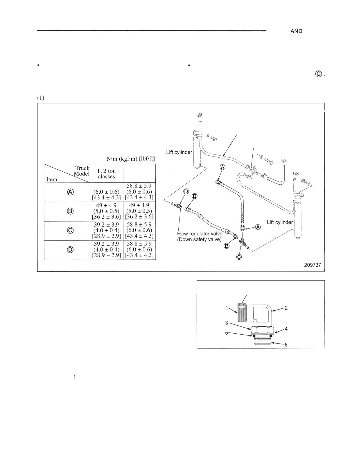
7. Installing hydraulic lines
General precautions
Use care not to let abrasive dust or dirt to enter the
For assembling Elbow Connector (a fitting with
hydraulic system.
straight threads and O-ring seal) indicated by
Apply a film of oil to O-rings before installation.
follow the procedure "Installation of a fitting with
straight threads and 0-Ring seal" shown below.
Simplex Mast
Return hose
(for mast of 3.5 m in height or higher)
Return line connector
Tightening torques
Unit :
3 ton
class
58.8t5.9
Nut
Nut
Nut
Nut
Installation of a fitting with straight threads and
Different in shape
O-ring seal
between fitting types
1. Apply grease or hydraulic oil to O-ring and O-ring
seat in the housing side.
2. Turn lock nut 3 to move it as close to fitting body 2
as possible. Place washer 4 and O-ring seal 5
against the lock nut.
3. Tighten the fitting by hand. Once O-ring 5 is
placed in the position of housing and washer 4
Elbow body assembly
comes in contact with the surface of housing, turn it
1 End of fitting
4 Backup washer
back to adjust the mounting direction. Never loose
body
5 O-ring seal
more than turn.
(connects to tube)
6 End of fitting that
4. Tighten lock nut 3 to the specified torque.
2 Fitting body
goes into other part
3 Locknut
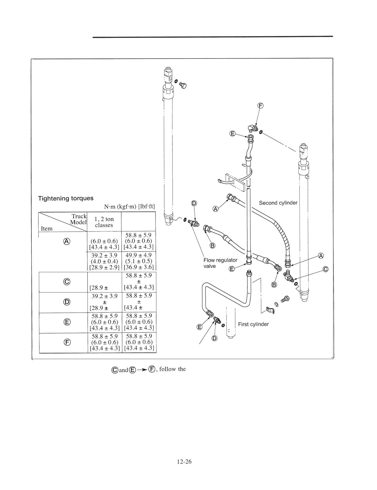
MAST AND FORKS
(2) Duplex Mast
Second cylinder
Unit :
3 ton
class
58.8t5.9
Nut
39.293.9
Nut
(4.0
9 0.4)
(6.0
0.6)
2.91
Nut
(4.0
0.4)
(6.0
0.6)
2.91
4.31
Nut
Nut
Flow regulator valve
209379
Note: When installing fittings
procedure under "Installation of a fitting with
straight threads and O-ring seal" on page 12-25.
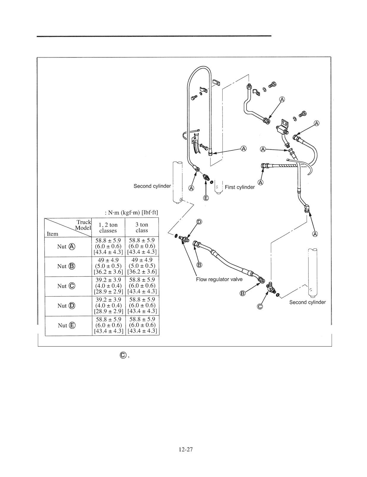
MAST AND FORKS
(3) Triplex Mast
Tightening torques
Unit
209738
Note: When installing fittings
follow the procedure
under "Installation of a fitting with straight threads
and O-ring seal" on page 12-25.
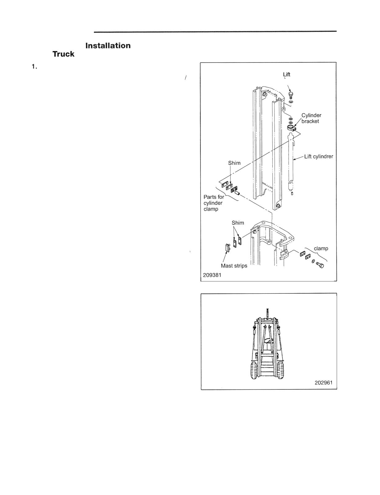
MAST AND FORKS
Removal and
of Mast Rollers and Strips without Removing Mast
from
Simplex Mast
cylinder set bolt
The mast rollers and strips can only be removed
installed when the inner mast is positioned lower than
the outer mast. This can be achieved as follows:
(I) Disconnect the lift bracket assembly.
(2) Lift the front of the truck by 15 to 20 cm (5.9 to 7.9
in .), and place blocks to support the truck.
(3) Remove the set bolts at the top of the lift cylinders.
Place a sling around the inner mast. Lift the inner mast
using a hoist connected to the sling in order to
disengage the lift cylinders' piston rods from the inner
mast. Remove the hose guard.
(4) Remove the lift cylinder clamp bolts, and separate the
lift cylinders from the outer mast. Pull out the lift
cylinders from the seats at the bottom of the outer
mast. Tilt the cylinders until they rest on the outer
mast cross member. Using a rope, fix the cylinders
onto the cross member.
(5) Using the hoist, slowly lower the inner mast until the
mast contacts the lift cylinders.
(6) The main rollers of the inner and outer masts can now
Parts for
cylinder
be removed. It is recommended that before attempting
to remove the main rollers, remove the mast strips and
shims as they tend to drop easily.
(7) Adjust shims for the main rollers and mast strips as
required.
Reassembly follows the above-described disassembly
procedures in reverse.
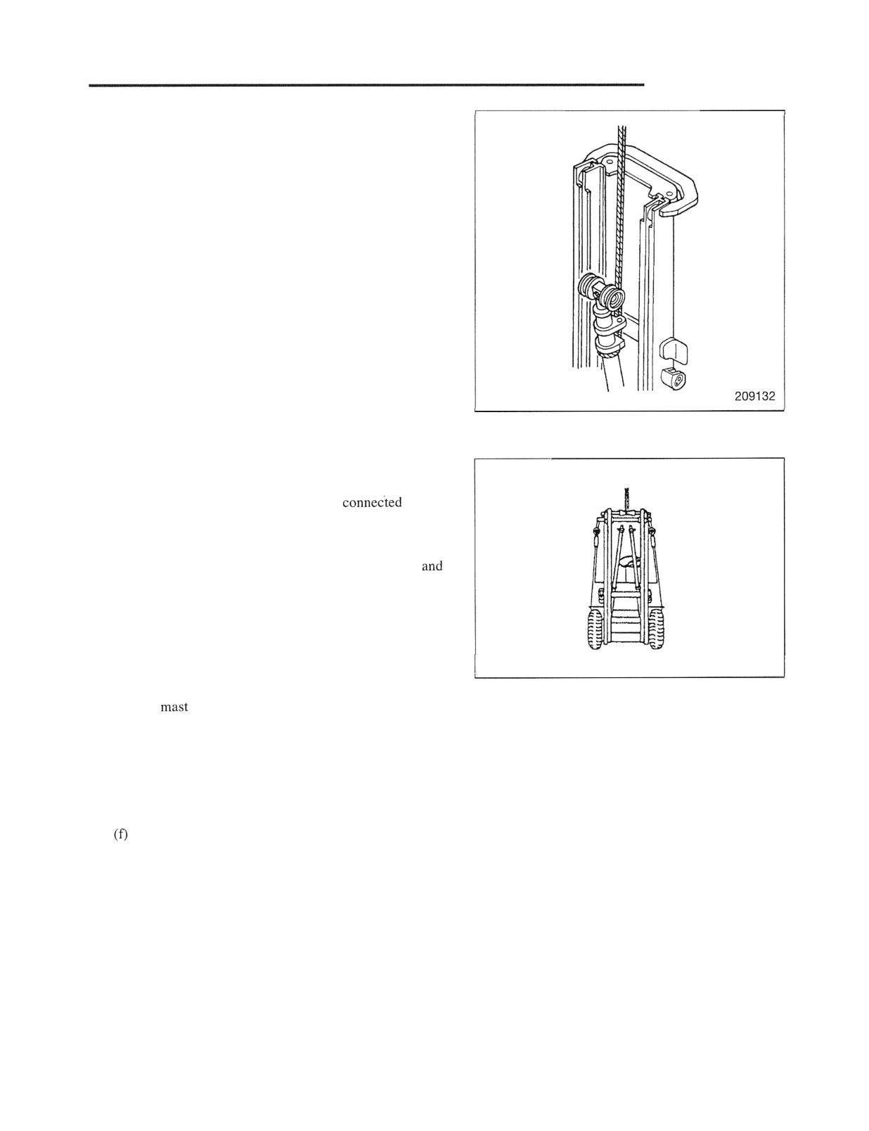
MAST AND FORKS
2. Duplex Mast
(1) Disconnect the lift bracket assembly.
(2) Remove the first lift cylinders as follows:
(a) For each of the cylinders: Place a sling around the
cylinder. Using a hoist connected to the sling,
slightly lift the cylinder. The sling should be
hitched firmly around the cylinder to prevent the
cylinder from slipping down.
(b) Remove the cylinder mounting bolts. Using the
hoist, slowly lift and remove the cylinder.
Note: The remaining procedures are exactly the same as
those for the simplex mast models.
(3) Place the inner mast lower than the outer mast as
follows:
(a) Lift the front of the truck by 15 to 20 cm (5.9 to
7.9 in.), and place blocks to support the truck.
(b) Remove the set bolts at the top of the second lift
cylinders. Place a sling around the inner mast.
Lift the inner mast using a hoist
to the
sling in order to disengage the lift cylinders' piston
rods from the inner mast. Remove the hose guard.
(c) Remove the second lift cylinder clamp bolts,
separate the cylinders from the outer mast. Pull
out the lift cylinders from the seats at the bottom of
the outer mast. Tilt the cylinders until they rest on
the outer mast cross member. Using a rope, fix the
cylinders onto the cross member.
202961
(d) Using the hoist, slowly lower the inner mast until
the
contacts the second lift cylinders fixed to
the cross member.
(e) The main rollers of the inner and outer masts can
now be removed. It is recommended that before
attempting to remove the main rollers, remove the
mast strips and shims as they tend to drop easily.
Adjust shims for the main rollers and mast strips as
required.
Reassembly follows the above-described disassembly
procedures in reverse.
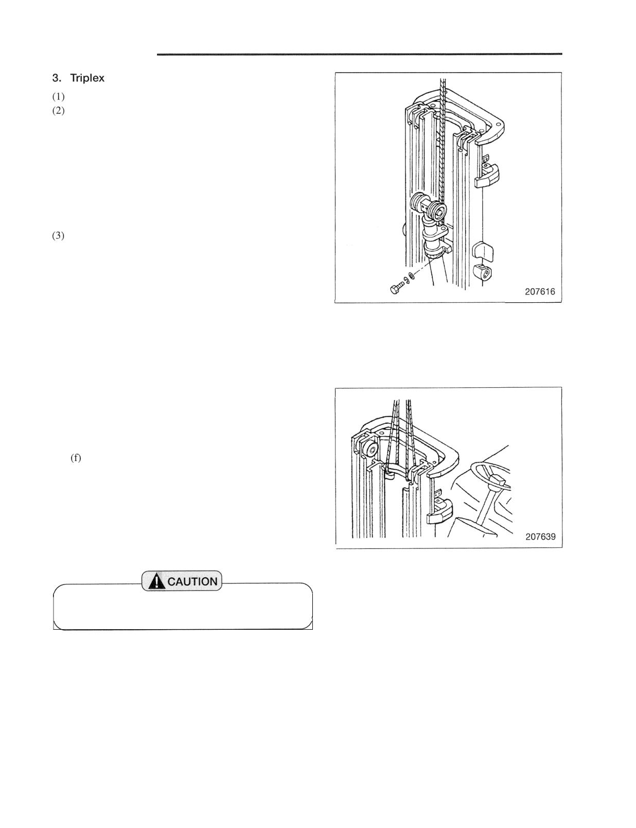
MAST AND FORKS
Mast
Disconnect the lift bracket assembly.
Remove the first lift cylinders as follows:
(a) For each of the cylinders: Place a sling around the
cylinder. Using a hoist connected to the sling,
slightly lift the cylinder. The sling should be
hitched firmly around the cylinder to prevent the
cylinder from slipping down.
(b) Remove the cylinder mounting bolts. Using the
hoist, slowly lift and remove the cylinder.
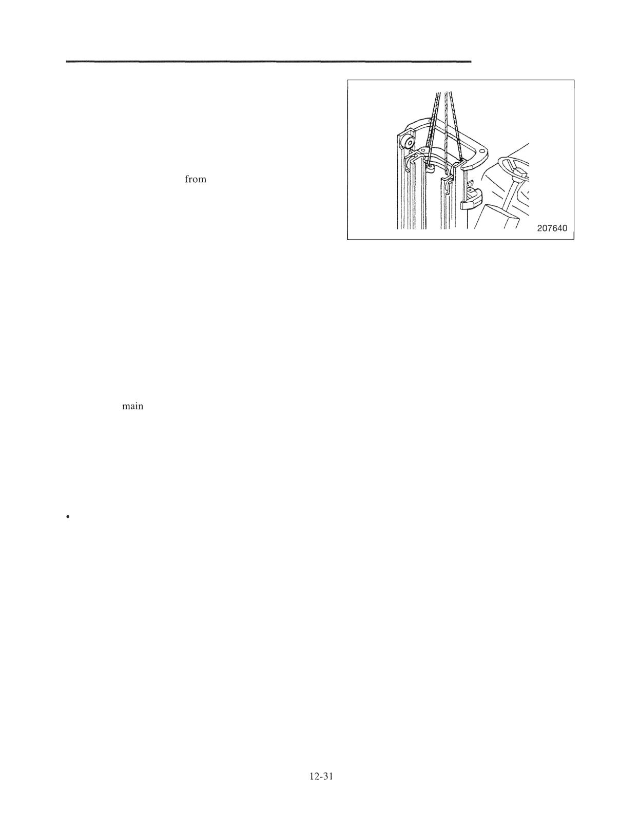
Place the inner mast lower than the middle mast as
follows:
(a) Lift the front of the truck by 15 to 20 cm (5.9 to
7.9 in.), and place blocks to support the truck.
(b) Place a sling around the upper cross member of the
inner mast. Using a hoist connected to the sling,
slightly lift the inner mast.
(c) Remove the guards for the second lift chain
wheels.
(d) Disconnect the second lift chains at the outer mast
ends, and place the loose ends on the floor beyond
the inner mast.
(e) Lower the inner mast to such a height that allows
the mast rollers to be removed.
Support the inner mast with wood blocks.
(g) The main rollers of the inner and middle masts can
now be removed. It is recommended that before
attempting to remove the main rollers, remove the
mast strips and shims as they tend to drop easily.
(h) Adjust shims for the main rollers and mast strips as
required.
I
With the mast disassembled as above, it is not
, possible to remove the second lift cylinders.
MAST AND FORKS
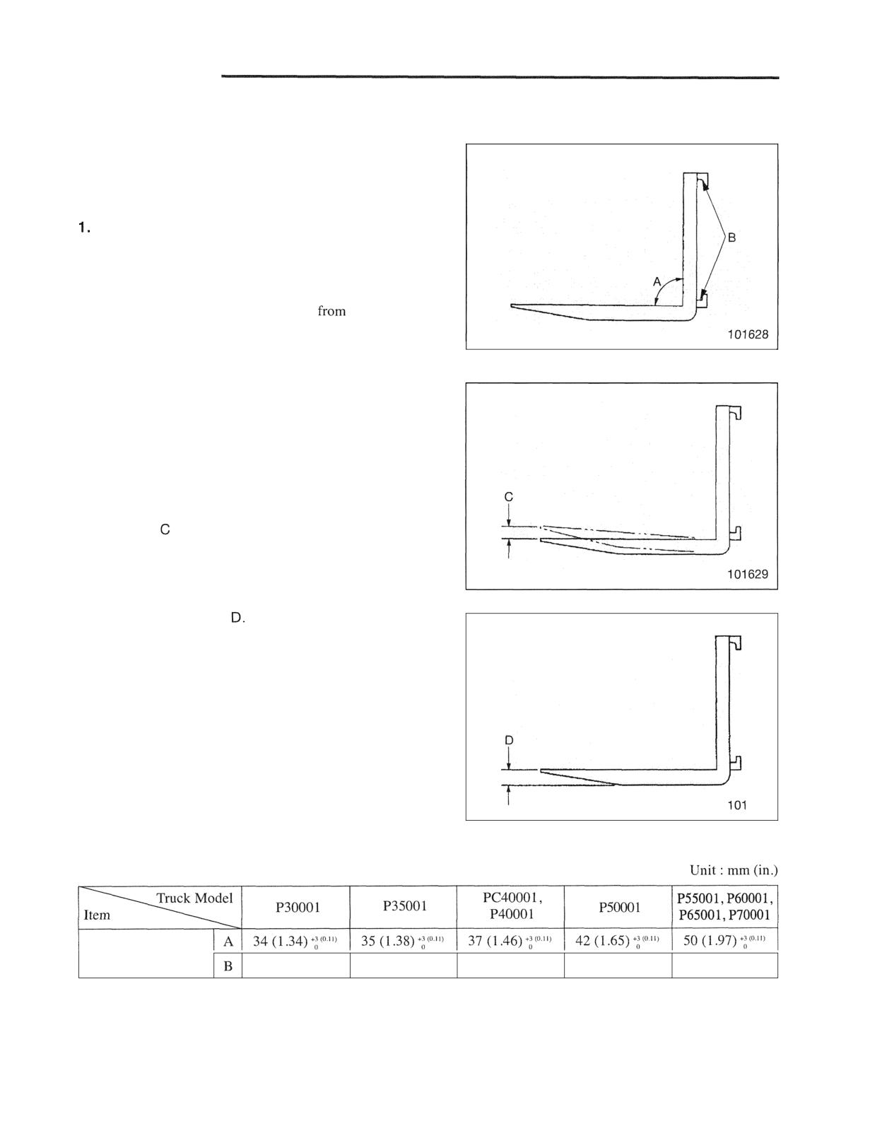
(4) Place the middle mast lower than the outer mast as
follows:
(a)
Lift the inner mast to the height of the middle
mast, then place wood blocks for support.
(b)
Hitch slings to both middle mast and inner mast,
and lift them with a hoist.
(c)
Remove set bolts
the upper sections of the
second lift cylinders, then lift the middle mast and
inner mast to separate the second lift cylinder from
the middle mast.
(d)
Remove two lift cylinder clamps, dismount the
second lift cylinders from the mounting sections at
the lower outer mast section. Tilt the cylinders by
moving the top sections towards the center of the
truck. Using a rope, fix the cylinders onto the
cross member.
(e)
Lower the middle mast and inner mast until mast
rollers (outer mast upper roller and middle mast
lower roller) can be moved.
(f)
Support the middle mast and inner mast with wood
blocks.
(g)
The
rollers of the inner and outer masts can
now be removed. It is recommended that before
attempting to remove the main rollers, remove the
mast strips and shims as they tend to drop easily.
(h)
Adjust shims for the main rollers and mast strips as
required.
For reassembling, follow the disassembly sequence in
reverse.
MAST AND FORKS
Inspection and Adjustment
The inspection and adjustment in this chapter can be done
without dismounting or disassembling. Conduct inspection
whenever a defect is suspected.
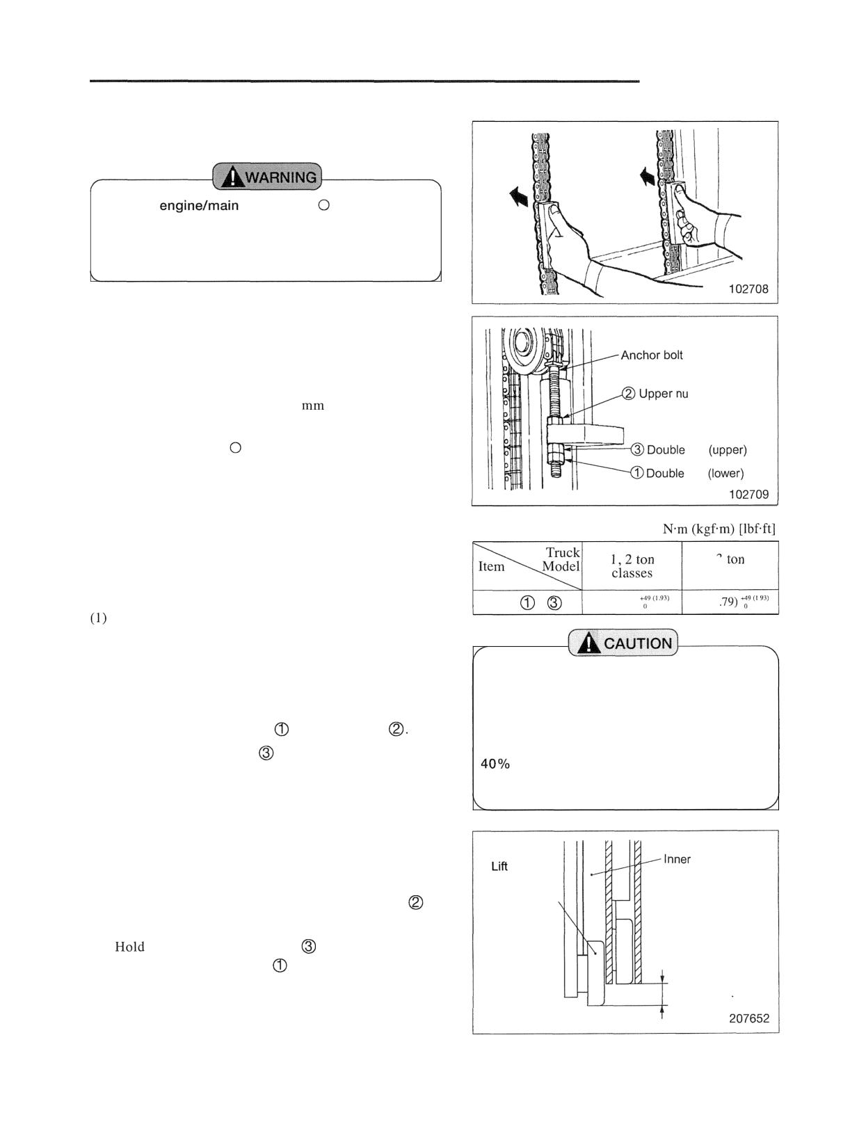
Forks (all mast models)
(1) Carefully inspect the forks for cracks. Special
attention should be given to the heel section A, all weld
areas and mounting brackets B.
Forks with cracks shall be removed
service.
Magnetic particle inspection is generally preferred due
to its sensitivity and the ease of interpreting the results.
For correct inspection, remove the painting from the
inspecting portion.
(2) Check the difference in height of one fork tip to the
other when mounted on the fork carrier. A difference
in fork tip height can result in uneven support of the
load and cause problems when loaded.
The maximum allowable difference in fork tip
elevation is 5 mm (0.20 in.) for pallet forks.
Replace one or both forks when the difference in fork
tip height exceeds the maximum allowable difference.
(3) Check the fork blade
The fork should be withdrawn
from service if the thickness is reduced to less than the
allowable thickness.
630
A: Standard value B: Repair or service limit
Fork thickness
31 (1.22)
32 (1.26)
35 (1.38)
40 (1.57)
45 (1.77)
MAST AND FORKS
2. Chain Tension lnspection and Adjustment
(Simplex Mast)
Turn the
key to the
(OFF) position
before making the inspection or adjustment of lift
chains, anchor bolts and nuts. Place blocks below
the forks when they are lifted.
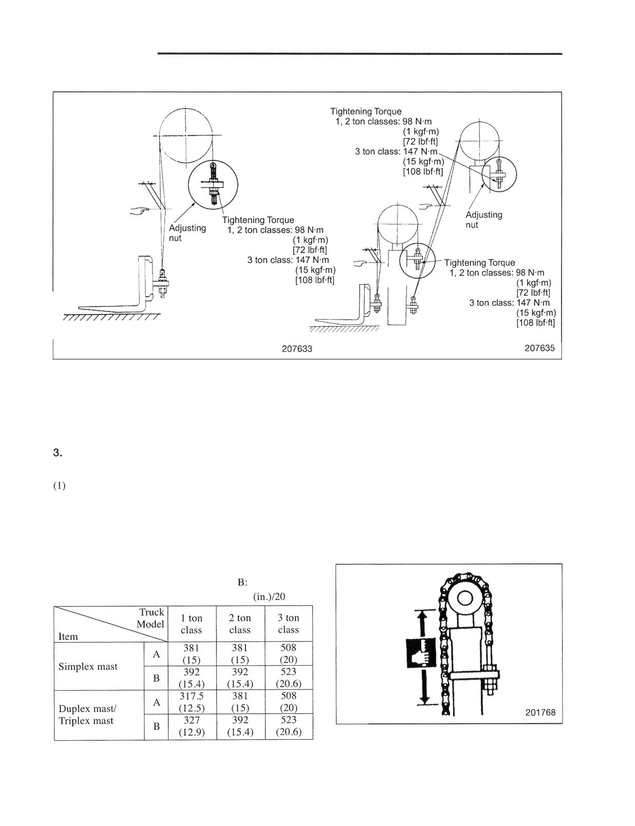
Inspection of chain tension
(1) Place the mast vertical on a level ground, then lower
the forks to the ground. Make sure that the lift
cylinders are fully retracted.
t
(2) Raise the forks approx.
100
(4.0 in.) from the
ground.
(3) Turn the key to the (OFF) position.
nut
(4) Place blocks approx.
90 mm (3.5 in.) high below the
nut
forks.
(5) Push the chains at the middle point between the chain
Tightening torque
Unit :
wheel and chains fixed end on the lift bracket. Check
the right and left chains for even tightness.
3
class
Adjustment of right and left chain balance
Nuts
,
98 (3.86)
147
(5
Remove the blocks below the forks. Start the engine.
(2) Lower the forks to the ground and tilt forward until the
tips come in contact with the ground. The chains are
After the adjustment, raise and lower the lift
now slack to facilitate the adjustment.
bracket several times. Then check the
(3) Stop the engine.
position of lift bracket when lift cylinder is
fully retracted. Make sure the protrusion of
(4) Loosen double nut (lower)
, then upper nut
each lift bracket main roller does not exceed
(5) Turn double nut (upper)
to adjust the chain tension.
of the roller diameter. If it exceeds,
(6) Start the engine, and place the mast vertical again.
elongation of chains is suspected.
(7) Repeat (2) through ( 5 ) of procedure 1, to check the
chain tension and adjust it as needed.
Tightening of nuts after adjustment
mast
bracket
lower roller
(1) Hold the anchor bolt at two flats with a wrench so as
\
not to twist the chain, the tighten the upper nut
to
the specified torque.
(2)
the double nut (upper)
with a wrench and
tighten double nut (lower)
to the specified torque.
40% of the roller
diameter or less
MAST AND FORKS
Duplex and Triplex Models
Note: The inspection and adjustment procedures are
completely the same as those for simplex mast
models. Follow the procedures in the previous page
to perform inspection or adjustment as necessary.
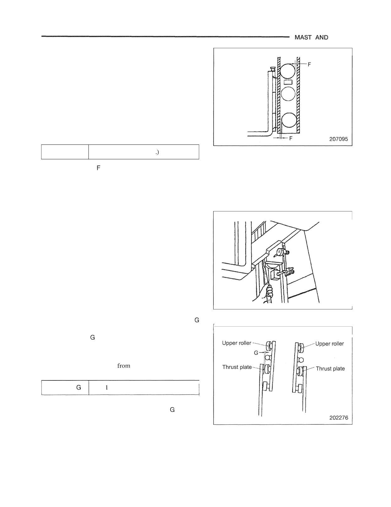
Checking Chain Elongation
(all mast models)
Apply maximum load evenly on both forks and expand
chain.
(2) Measure the length of 20 links of chain. When the
length exceeds the service limit specified in the table
below, replace the chain with new one.
Chain elongation
A: Standard value (New)
Service limit
Unit : mm
links
20 links
FORKS
4. Adjusting Clearance between Lift Bracket
Roller and Inner Mast (all mast models)
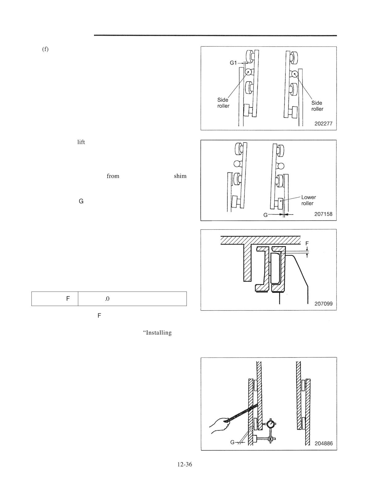
(1) Back-to-front clearance check on lift bracket main
rollers
(a) Raise the forks a little from the ground.
(b) Insert a bar between the upper part of lift bracket
and the inner mast, and push the inner mast to one
side. Using feeler gauges, measure the clearance F
between the main roller and inner mast on the
opposite side.
Clearance F
1.0 mm (0.04 in or less
(c) If clearance
is out of specification, use oversize
rollers. Remove lift bracket from mast and replace
rollers with proper sized rollers. For roller
replacement procedure, refer to "Choosing rollers
of correct diameters" on pages 12-20.
(2) Right-to-left clearance check on lift bracket main
rollers and side rollers
(a) Raise the mast to the top.
(b) Set a dial indicator on the inner mast with its
contact point rested on the side of the lift bracket.
(c) Go over to the opposite side of the mast, and push
the lift bracket to one side with a bar. Set the
indicator to zero.
(d) Insert a bar between the inner mast and lift bracket
on the indicator side, and push the lift bracket to
the opposite side.
(e) Read the indicator. This reading is the clearance
between middle roller and thrust plate. If
clearance
is out of specification, it is necessary
to add shims to the seat of the roller to adjust to
correct clearance.
Note: Upper rollers are free
checking and adjusting.
Clearance
0. to 0.5 mm (0.004 to 0.020 in.)
For adjustment, refer to "Adjusting clearance
between
the middle roller and thrust plate" on page 12-20.
MAST AND FORKS
Lower the lift bracket slightly from the top, so that
the side roller comes in contact with the inner
mast, then check clearance GI between the side
roller. If clearance GI is out of specification, it is
necessary to add shims to the seat of the roller
bracket to adjust to correct clearance. Remove lift
bracket from mast and adjust the shim thickness.
For adjustment and installation procedures, refer to
"Adjusting clearance GI between the side roller
and inner mast" on page 12-21.
(g) With the
bracket at the top, check clearance G
between lower roller and mast. If clearance G is
out of specification, it is necessary to add shims to
the seat of the roller to adjust to correct clearance.
Remove lift bracket
mast and adjust the
thickness for the rollers. For adjustment and
installation procedures, refer to "Adjusting
clearance
between lower rollers and inner mast9'
on page 12-20.
5. Mast Roller Clearance Adjustment
(all mast models)
(1) Back-to-front clearance inspection on mast main rollers
(a) Tilt the mast fully backward.
(b) Using feeler gauges, measure the clearance F
between the inner mast lower roller and outer mast.
Clearance
1 mm (0.04 in.) or less
(c) If the clearance
is out of the specification, use
oversize rollers. For mast roller replacement and
installation procedures, refer to
mast
rollers" on page 12-22.
(2) Right-to-left clearance inspection on inner mast main
rollers
(a) Raise the mast to the top.
(b) Set a dial indicator on the inside of the outer mast
with its contact point rested on the inner mast.
(c) Go over to the opposite side of the mast, and push
the inner mast against the outer mast. Set the
indicator to zero.
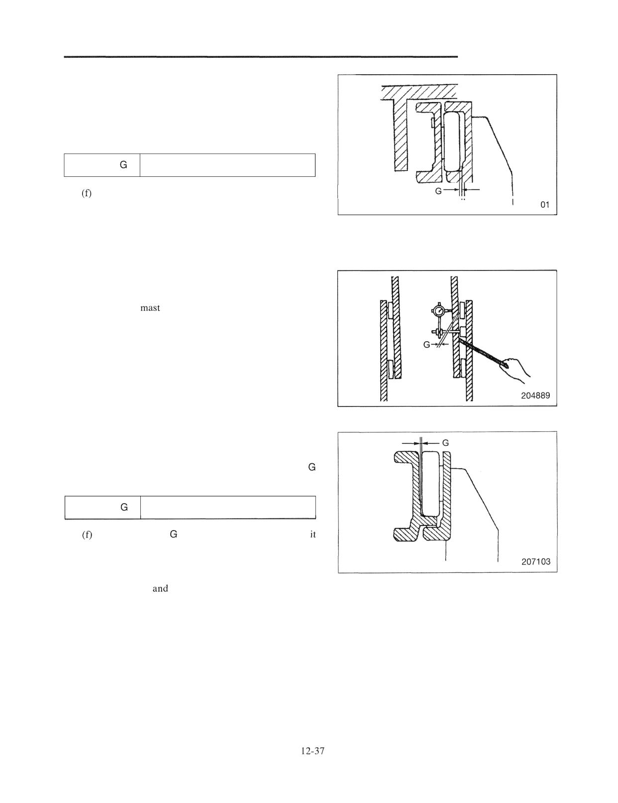
MAST AND FORKS
(d) Insert a bar between the outer and inner masts on
the indicator side, and push the inner mast to the
opposite side.
(e) Read the indicator. This reading is the clearance G
between inner mast roller and outer mast.
Clearance
0.1 to 0.5 mm (0.004 to 0.020 in .)
If the clearance G is out of specification, it is
,
necessary to add shims to the seat of the roller to
2071
adjust to correct clearance. For adjustment and
installation procedures, refer to "Installing rnast
rollers" on page 12-22
(3) Right-to-left clearance check on outer mast main
rollers
(a) Raise the
to the top.
(b) Set a dial indicator on the outer mast with its
contact point rested on the inner mast.
(c) Go over to the opposite side of the mast, and push
the outer mast against the inner mast with a bar.
Set the indicator to zero.
(d) Insert a bar between the outer and inner mast, and
push the inner mast to the opposite side.
(e) Read the indicator. This reading is the clearance
between outer mast roller and inner mast.
Clearance
0.1 to 0.5 rnm (0.004 to 0.020 in.)
If the clearance
is out of specification, adjust
by shims.
It is necessary to add or remove shims at the seat
of the roller to adjust to correct clearance. For
adjustment
installation procedures, refer to
"Installing mast rollers" on page 12-22.
MAST AND FORKS
6. Mast Strip Clearance,
and
Adjustment (all mast models)
(1) Check the clearance
with the clearance between the
outer mast rollers and inner mast rolling contact
setting to zero (0) in maximum lift position.
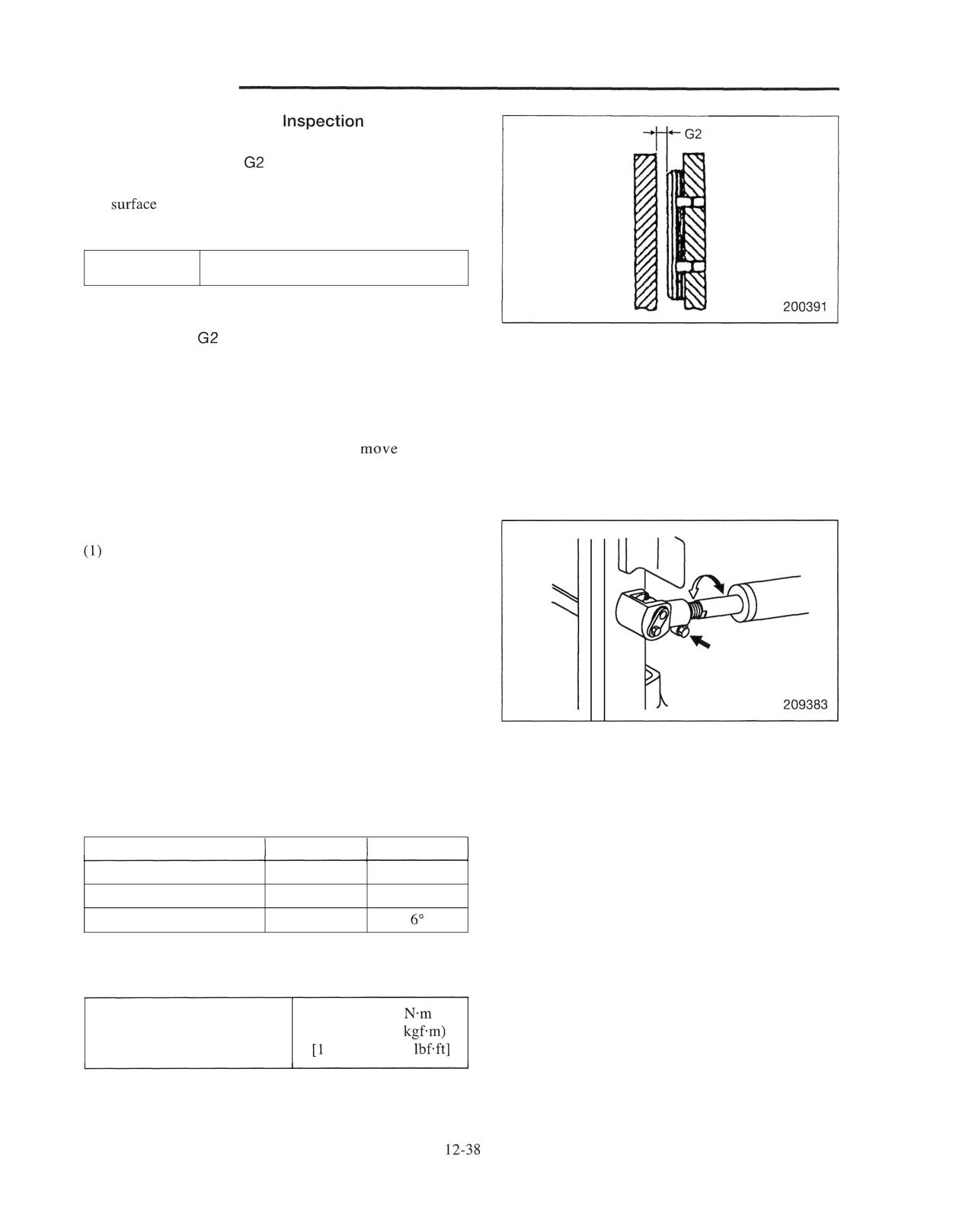
Clearance G2
0.1 to 0.5 mm (0.004 to 0.020 in.)
(2) If clearance
is out of specification, adjust it by
adding or removing shims. For adjustment procedure,
refer to "Measuring and adjusting clearance G2
between mast strip and inner mast" on page 12-23.
(3) After adjusting the all clearance, move the mast and lift
bracket slowly to ensure that they
smoothly
through their full stroke.
7. Tilt Angle Adjustment (all mast models)
Adjust the tire pressure correctly and park the truck on
a level ground.
(2) Tilt the mast fully backward and stop the engine.
(3) Measure the backward tilt angle of the mast at both
sides.
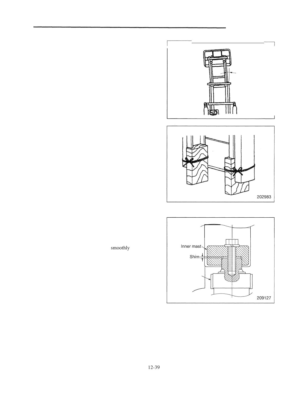
(4) To adjust the tilt angle, loosen the bolt of tilt cylinder
socket, and adjust the rod length by turning the rod.
Adjust cylinder so that there is no difference in stroke
tilt angle between the cylinders, right and left.
Note: It is not necessary to adjust the forward tilt angle if
the backward tilt angle is properly adjusted.
Standard tilt angle
Mast model
Forward
Backward
Simplex Mast
6"
12"
Duplex Mast
6"
12"
Triplex Mast
6"
(5) After adjusting the tilt angle, tighten the socket bolts to
the specified torque.
153 to 182
Tightening torque for tilt
(15.6 to 18.6
cylinder socket bolt
12.8 to 134.5
MAST AND FORKS
8. Right and Left Lift Cylinder Stroke Inspection
and Adjustment (all mast models)
(1) Slowly raise the inner mast, and observe how the
piston rods, left and right, stop at the moment the inner
mast reaches its maximum height.
(2) If the top of the inner mast jolts at that moment, make a
shim adjustment. Abnormal condition can be detected
by a little time lag in stopping between the piston rods,
left and right, and shaking of the rod with a longer
cylinder stroke.
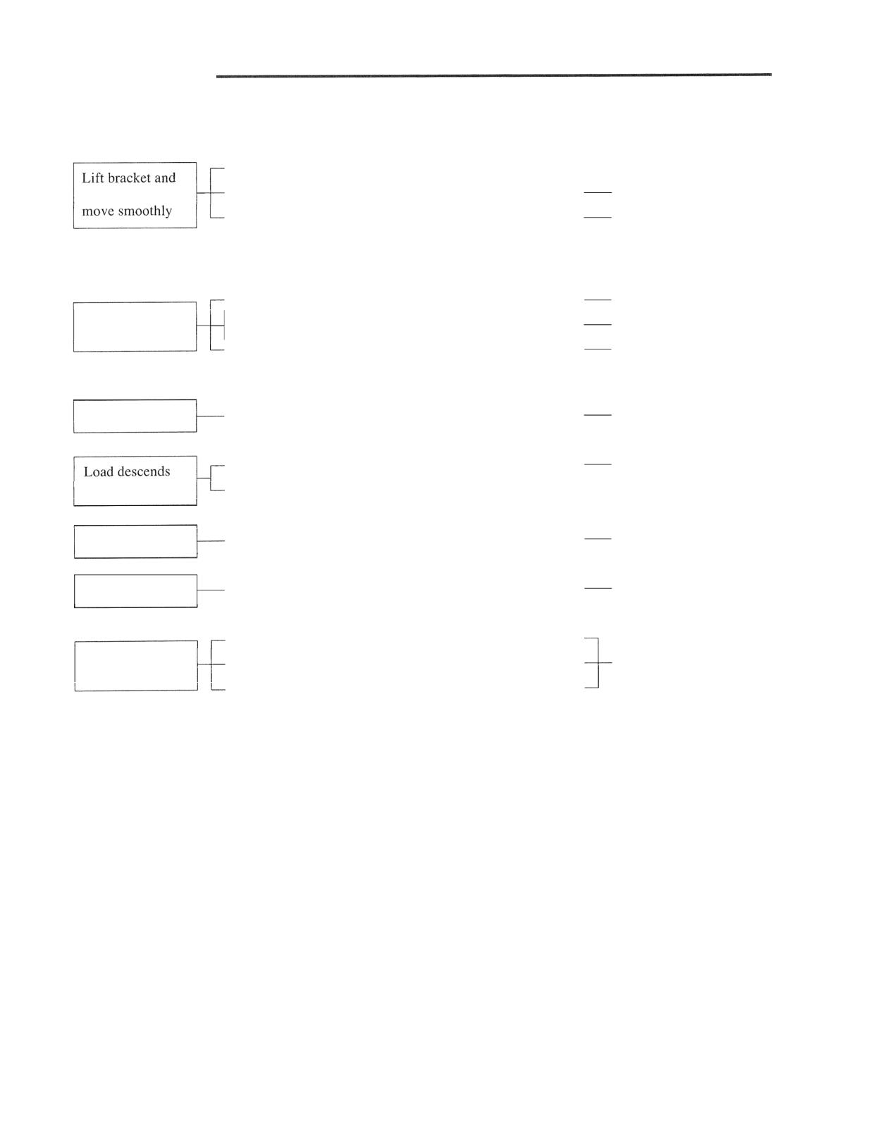
(3) Adjusting method
(a) Raise the inner mast, place blocks under the right
and left sides of the inner mast, and lower the mast
until its rests on the blocks.
(b) Remove the set bolt at the top of lift cylinder
which showed earlier stroke end, retract the piston
rod, and insert shims at the top of piston rod end.
Note: When retracting piston rod, push the lift lever to
lowering direction for releasing the oil in the
cylinders.
(c) Extend the piston rod, and tighten the cylinder set
bolt. Remove the blocks from under the inner
mast.
(d) Slowly lower the inner mast to the bottom to
ensure the piston rods move
and that the
left and right lift cylinders come to the end of
stroke simultaneously at the maximum lift position
of inner mast.
Cylinder
bracket
MAST AND FORMS
Troubleshooting
Clearance between lift rollers and side rollers incorrect
-
Readjust clearance.
inner mast will not
Rollers binding on their shafts
Relubricate of replace.
Mast strip clearance incorrect
Shim adjust.
0.1 to 0.5 mm
(0.004 to 0.020 in .)
TOO much clearance on side rollers
Readjust by adding shims.
Lift bracket or
Lift chains unequally tensioned
Readjust.
inner mast binds
Shim adjustments unequally made on between left
Readjust.
and right lift cylinders (at maximum height)
Mast makes noise
Rollers not rotating smoothly on their shafts
Relubricate or replace.
Lift cylinder packing damaged
Replace.
(drift)
Sliding (inside) surface of lift cylinder tube damaged
-
Replace.
Whole mast shakes
Mast-support bushing or metal worn
Retighten or replace.
Mast is distorted
Off-center loading or overload
Replace mast assembly
Finger bar bent
Fork tips differ in
Forks bent
Repair or replace.
height
Un-even loading
MAST AND FORKS
A: Standard value B: Repair or service limit
Unit: mm (in.)
Truck Model
2 ton
3
class
class
class
Item
I A
381 (15)
381 (15)
508 (20)
Chain extension
Chains
links
(Duplex)
B
Main roller external diameter
Rollers
external diameter
Width of outer mast B
A
610 (24)
670 (26.4)
670 (26.4)
Duplex mast
Width of inner
B2
A
516 (20.3)
568 (22.4)
568 (22.4)
Width of lift bracket
A
408 (16.1)
458
458 (18)
Dimensions
of outer mast
A
610 (24)
670 (26.4)
670 (26.4)
(Reference)
Width of middle mast
A 516 (20.3)
568 (22.4)
568 (22.4)
-
Triplex mast
Width of inner mast B2
A
426 (16.8)
468 (18.4)
468 (18.4)
Width of lift bracket C
A 318 (12.5)
358 (14.1)
358 (14.1)
Clearance between main roller circumference
1.0 (0.04) or less
and mast thrust surface F
Masts
Clearance between main roller side surface and
A
mast thrust surface
I
I
Clearance between inside mast and mast strip G2 A
0. to 0.5 (0.004 to 0.020)
Clearance between upper and lower roller
Clearances
(0.04) or less
circumference and inner mast thrust surface F
Clearance between middle roller side
surface and inner mast thrust plate
Lift brackets
Clearance between lower roller side
A
0.1 to 0.5 (0.004 to 0.020)
surface and inner mast thrust surface
Clearance between side roller circumference and
inner mast surface
I
Finger bar bend
A
5
(0.2) or less
1
1
Fork thickness
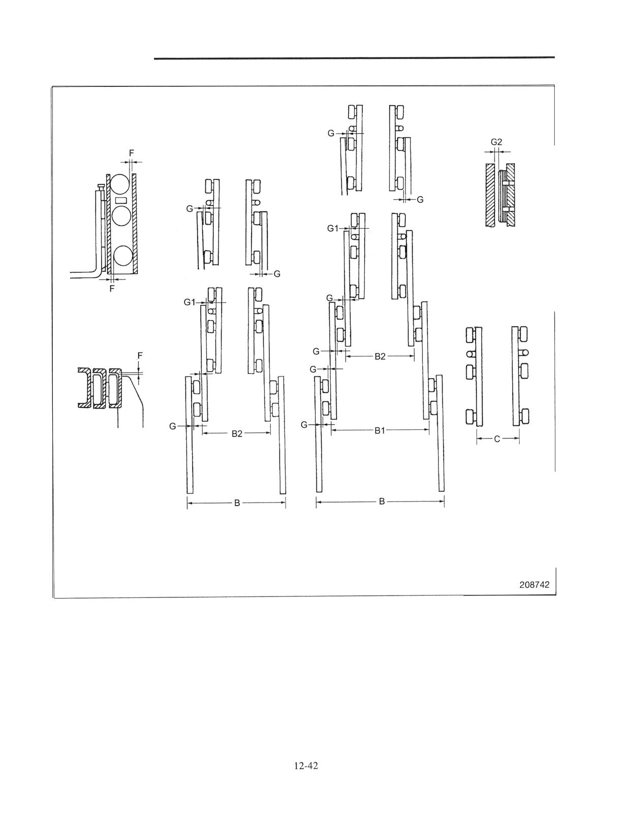
MAST AND FORKS
Lift bracket
Simplex mast,
Triplex mast
Duplex mast
Mast width is slightly wide at the lower portion than at the upper portion.
Measure the clearance at the mast upper position.
CE DATA
Maintenance Schedule
3.
1
Tightening Torques for Standard Bolts and Nuts
6
Periodic Replacement Parts
8
Location of Periodic Replacement Parts
9
Lubrication nstructions
...........................................13.
Lubrication Chart
13
10
Fuel and Lubricant Specifications
. 11
Refill
Capacities
13
12
Weight of Major Components (Approximate
Special
Tools
13- 14
Special Service Tools
13- 14
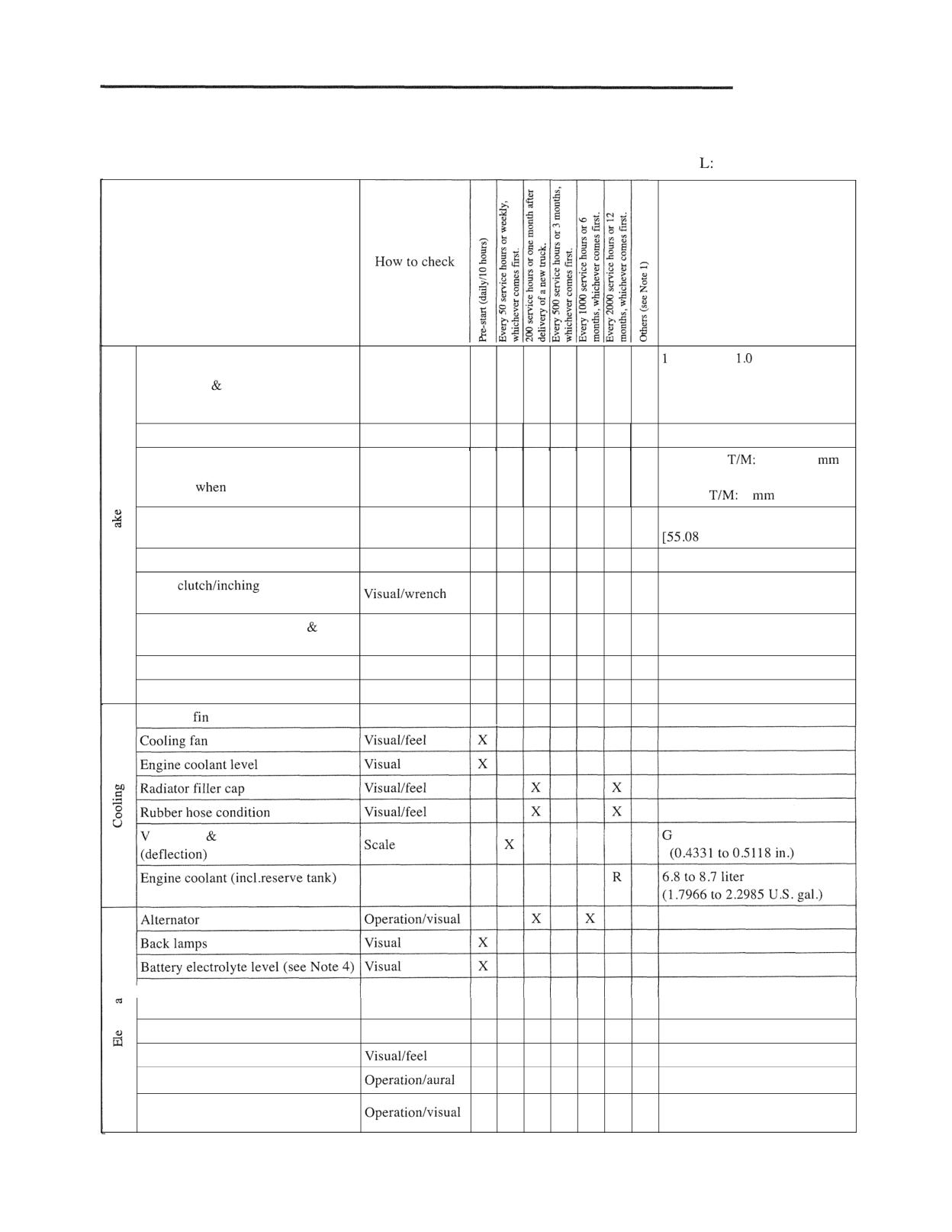
SERVICE DATA
Maintenance Schedule
Abbreviation-
X: Check, C: Clean, D: Drain, Lubricate, R: Replace
Inspection point
Service data
ton: 0.5 to
mm
(0.0197 to 0.0394 in.)
Brake drum shoe clearance
Feeler gauge
X
2, 3 ton: 0.1 to 0.35 mm
(0.004 to 0.014 in.)
Brake hose, pipes & joints
Visual
X
I
Powershift
1.5 to 6.5
Brake pedal clearance between pedal
Scale
X
(0.0591 to 0.2559 in.)
and floor
depressed
Manual
7
(0.2756 in.)
245 to 295 N (24.98 to 30.08 kgf)
Parking brake lever operating effort
Spring scale
X
to 66.32 lbf]
Service brake fluid level
Visual
X
Brake
pedal rod
L
(see Note 2)
Brake master cylinder hoses
R
rubber parts
Service brake fluid
R
135 cc (8.238 cu in.)
Brake wheel cylinder rubber parts
R
Radiator
(see Note 2)
Visual
C
C
belt (fan alternator) tension
asoline engine: 11 to 13 mm
Battery electrolyte specific gravity
Hydrometer
X
X
1.28 or higher
(see Note 4)
Driving interlock system
Operationlvisual
X
Electrical wires
X
X
Horn
X
Meter panel (instrument) lamps
X
(incl. parking brake and seat belt)
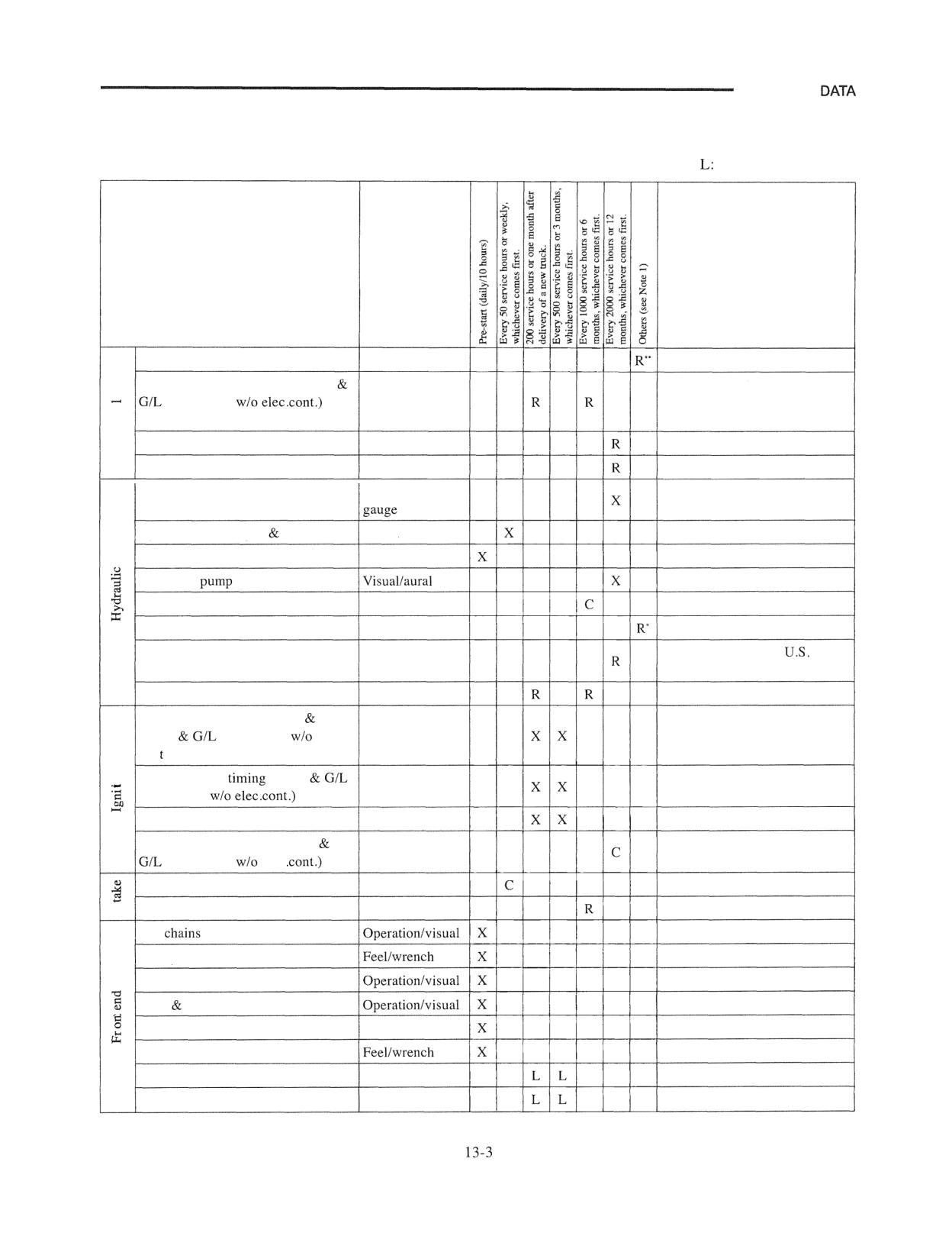
13-1
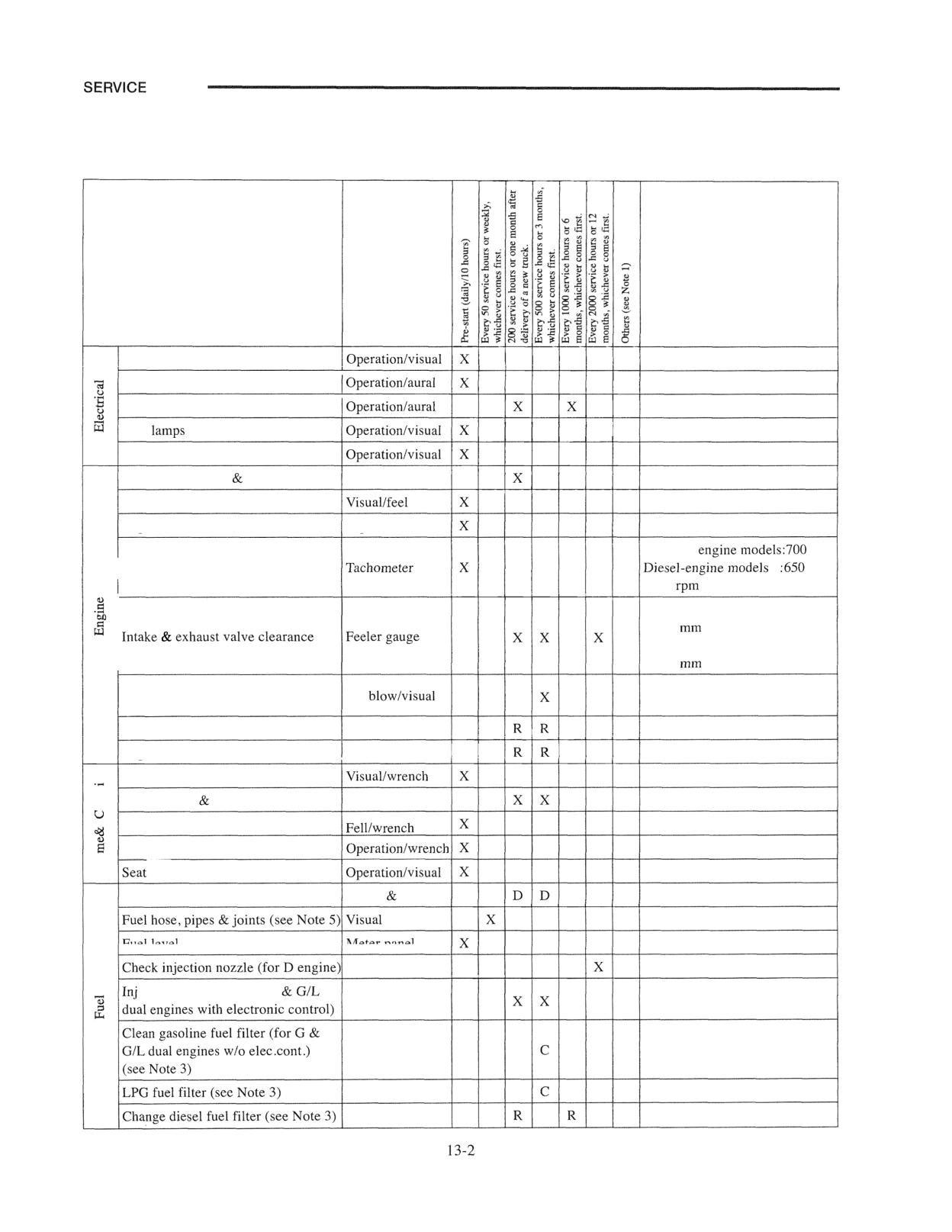
DATA
Abbreviation
X: Check, C: Clean, D: Drain, L: Lubricate, R: Replace
Inspection point
How to check
Service data
Mast interlock system
I
Parking brake buzzer
I
Starter
Stop
Working & head lamps
Cylinder head bolt manifold nut
Wrench
Engine (exhaust, noise, vibration)
Engine oil level
Dip stick
Gasoline
rpm
Idling speed (for Carburetor and
to
diesel engine)
700
Gasoline engine (hot):
0.38
(0.0150 in.)
Intake exhaust valve clearance
Feeler gauge
Diesel-engine models (cold):
0.25
(0.0098 in.)
Positive crankcase ventilation valves
Air
& hoses
Engine oil
Engine oil filter
Frame assist grip
Loosen bolts nuts
Wrench
Overhead guard
Seat adjustment
belt
Tar in vaporizer (see Note 3)
Check drain
Fuel level
Meter panel
ection nozzle (for G, LP
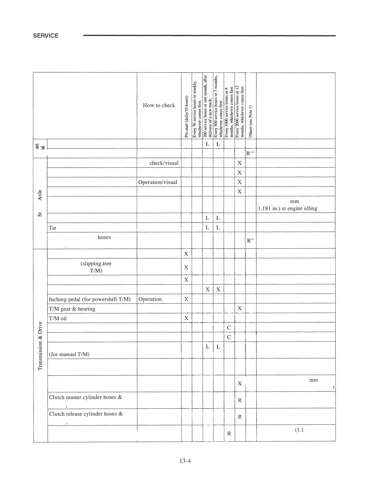
SERVICE
Abbreviation
X: Check, C: Clean, D: Drain, Lubricate, R: Replace
Inspection point
How to check
Service data
Fuel hose
Change gasoline fuel filter (for G
dual engine
(see Note 3)
LPG fuel filter (see Note 3)
Vaporizer rubber parts
I
I
Oil pressure
Control valve
Hydraulic hose, pipes joints
Visual
Hydraulic oil
Visual
Hydraulic
Hydraulic tank strainer
Visual
Hydraulic hose (high-pressure hose)
1 ton: 28 liter (7.398
gal.)
Hydraulic oil
2, 3 ton: 39 liter (10.30 U.S. gal.)
Hydraulic tank return oil filter
Check distributor point, cap rotor
(for G
dual engine
elec.
con .)
Check ignition
(for G
dual engine
Spark plug gap
Plug gauge
Clean distributor inside (for G
dual engine
elec
Air cleaner element (see Note 2)
Visual
Air cleaner element (see Note 2)
Lift
Lift cylinder mounting bolts
Load backrest
Mast forks
Mast strip sliding surfaces
Visual
Tilt cylinder socket bolts
Lift chains (see Note 2)
Mast support (see Note 2)
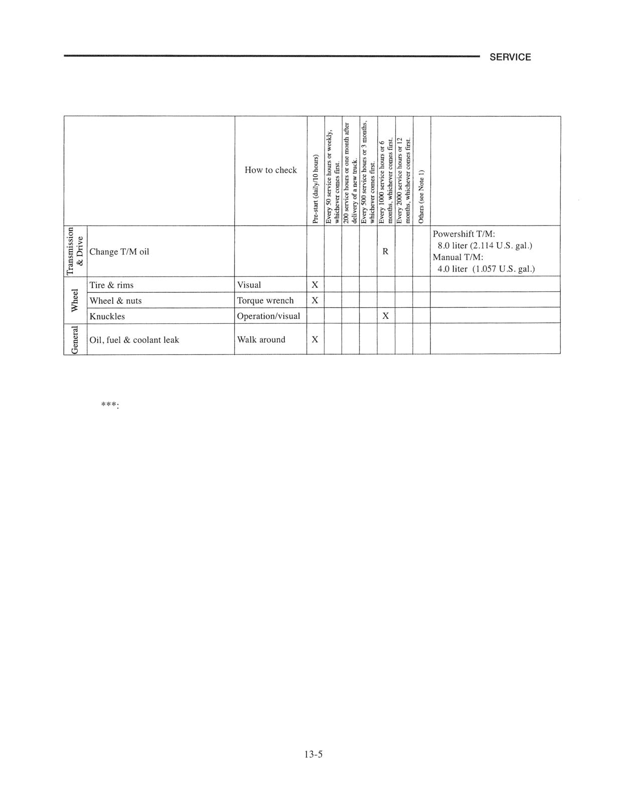
DATA
Abbreviation
X: Check, C: Clean, D: Drain, L: Lubricate, R: Replace
Inspection point
Service data
Tilt socket pins (see Note 2)
Lift chains
Front axle
Dye
Power steer cylinder
Operationlvisual
Rear axle
Steer gear box
Operationlvisual
Play 15 to 30
(0.5906 to
Steer wheel
Operationlscale
X
8
King pins (see Note 2)
rod pins (see Note 2)
Power steer cylinder
&
rubber parts
Accelerator pedal
Operation
Check clutch
play &
fluids for manual
Check clutch pedal (for manual TIM)
Differential oil
Visual
Operation
Visual
Last chance filter (TIM control valve) Visual
TIM strainer
Visual
Lubricate clutch pedal shifter shaft
Lubricate TIM change levers
(for manual TIM)
Adjust inching pedal for powershift
Cable play: 0.5 to 1 5
Scale
TIM
(0.0197 to 0.059 1 in.:
rubber parts
rubber parts
1 ton: 4.2 liters
U.S. gal.)
Differential oil
2,3 ton: 5 liters (1.3 U.S. gal.)
I
DATA
Abbreviation
X: Check, C: Clean, D: Drain, L: Lubricate, R: Replace
Inspection point
Service data
Note 1: *:
Change in 1 to 2 years
**: Change in 2 years
Change in 2 to 4 years
Note 2: In corrosive or abrasive environments, clean, lubricate and change more frequently.
Note 3: When fuel with poor quality is used, check, drain, clean and change more frequently.
Note 4: Not required if battery is full maintenance free battery.
Note 5: Apply soap suds to the piping joints to check for any gas leakage after replacing the LPG tank.
DATA
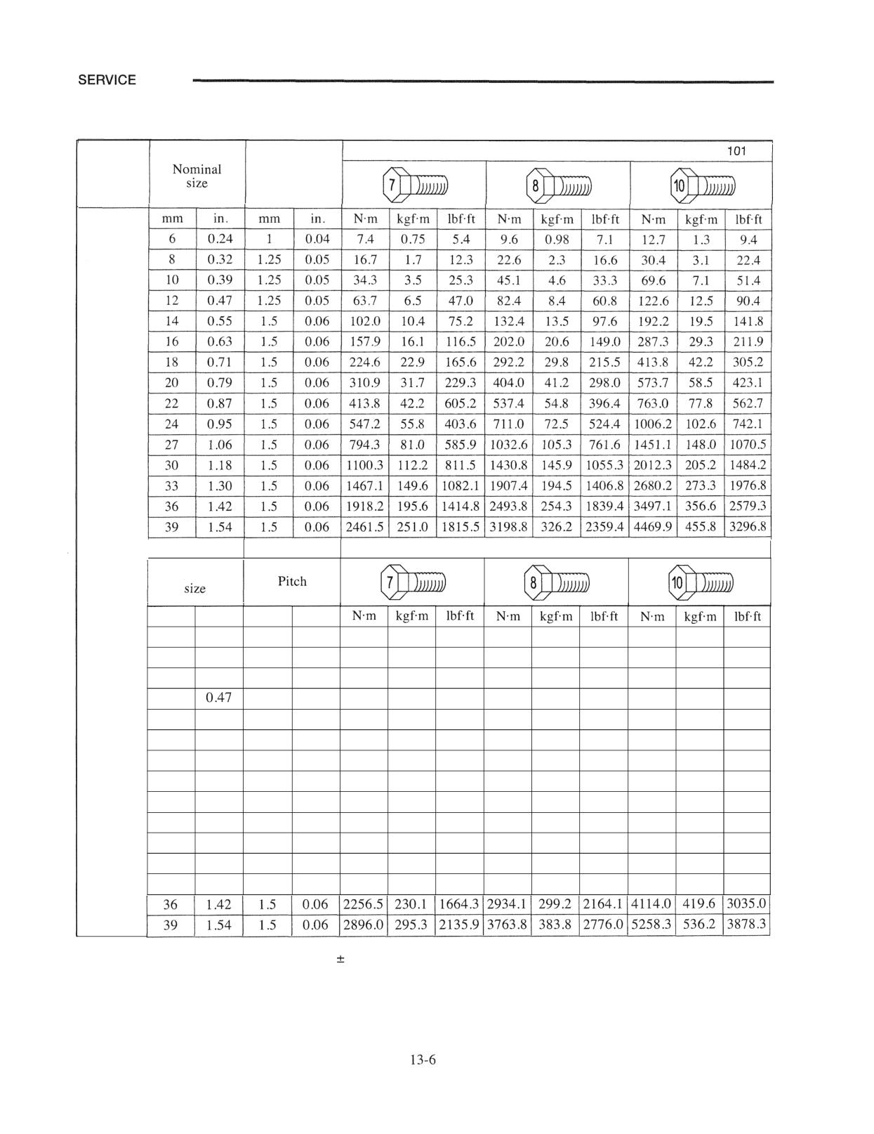
Tightening Torques for Standard Bolts and Nuts
With spring washer
656
Pitch
With spring washer
101656
Metric
I
fine
Nominal
thread
mm
in.
mm
in.
6
0.24
1
0.04
8.6
0.88
6.4
10.8
1.1
8.0
14.7
1.5
10.8
8
0.32
1.25
0.05
19.6
2.0
14.5
26.5
2.7
19.5
36.6
3.7
26.8
10
0.39
1.25
0.05
41.2
4.2
30.4
53.0
5.4
29.1
81.4
8.3
60.0
12
1.25
0.05
74.5
7.6
55.0
97.1
9.9
71.6
144.2
14.7
106.3
14
0.55
1.5
0.06
119.6
12.2
88.2
155.9
15.9
115.0
226.5
23.1
167.1
16
0.63
1.5
0.06
182.4
18.6
134.5
237.3
24.2
175.0
338.3
34.5
249.5
18
0.71
1.5
0.06
263.8
26.9
194.6
343.2
35.0
253.2
487.4
49.7
359.5
20
0.79
1.5
0.06
365.8
37.3
269.8
475.6
48.5
350.8
674.7
68.8
497.6
22
0.87
1.5
0.06
486.4
49.6
358.8
632.5
64.5
466.5
897.3
91.5
661.8
24
0.95
1.5
0.06
643.3
65.6
474.5
836.5
85.3
617.0
1183.7
120.7
873.0
27
1.06
1.5
0.06
934.6
95.3
689.3
1216.0
123.9
894.2
1707.3
174.1
1259.3
30
1.18
1.5
0.06
1294.5
132.0
954.8
1682.8
171.6
1241.2
2367.3
241.4
1746.0
33
1.30
1.5
0.06
1726.0
176.0
1273.0
2243.8
228.8
1654.9
3153.8
321.6
2326.1
Remarks: 1. The tolerance on the torque is
10%
2. The torques are for "dry" condition.
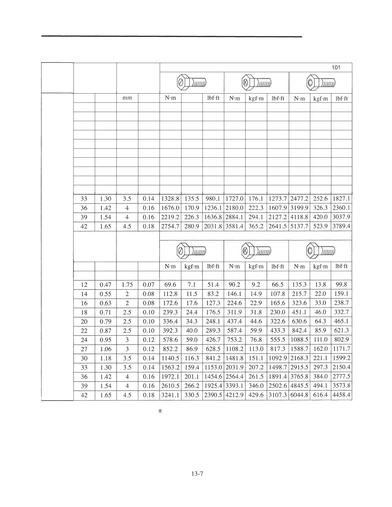
SERVICE DATA
With spring washer
656
Nominal
Pitch
size
mm
in.
in.
kgfm
10
0.39
1.5
0.06
33.3
3.4
24.6
43.1
4.4
31.8
67.7
6.9
49.9
12
0.47
1.75
0.07
58.8
6.0
43.4
76.5
7.8
56.4
115.7
11.8
85.3
14
0.55
2
0.08
96.4
9.8
70.9
124.5
12.7
91.9
182.4
18.6
134.5
16
0.63
2
0.08
147.1
15.0
108.5
191.2
19.5
141.0
274.6
28.0
202.5
18
0.71
2.5
0.10
203.0
20.7
149.7
264.8
27.0
195.3
383.4
39.1
282.8
20
0.79
2.5
0.10
286.4
29.2
211.2
371.7
37.9
274.1
536.4
54.7
395.6
22
0.87
2.5
0.10
383.4
39.1
282.8
499.2
50.9
368.2
725.9
74.0
535.2
24
0.95
3
0.12
492.3
50.2
363.1
640.4
65.3
472.3
924.8
94.3
682.1
27
1.06
3
0.12
724.7
73.9
534.5
942.2
96.1
695.1
1350.4
137.7
996.0
30
1.18
3.5
0.14
969.9
98.9
715.3
1259.2
128.4
928.7
1843.7
188.0
1359.8
With spring washer
101656
Metric
Nominal
Pitch
coarse
size
thread
mm
in.
mm
in.
10
0.39
1.5
0.06
39.2
4.0
28.9
51.0
5.2
37.6
79.4
8.1
58.6
Remarks: 1. The tolerance on the torque is
10%
2. The torques are for "dry" condition.
SERVICE DATA
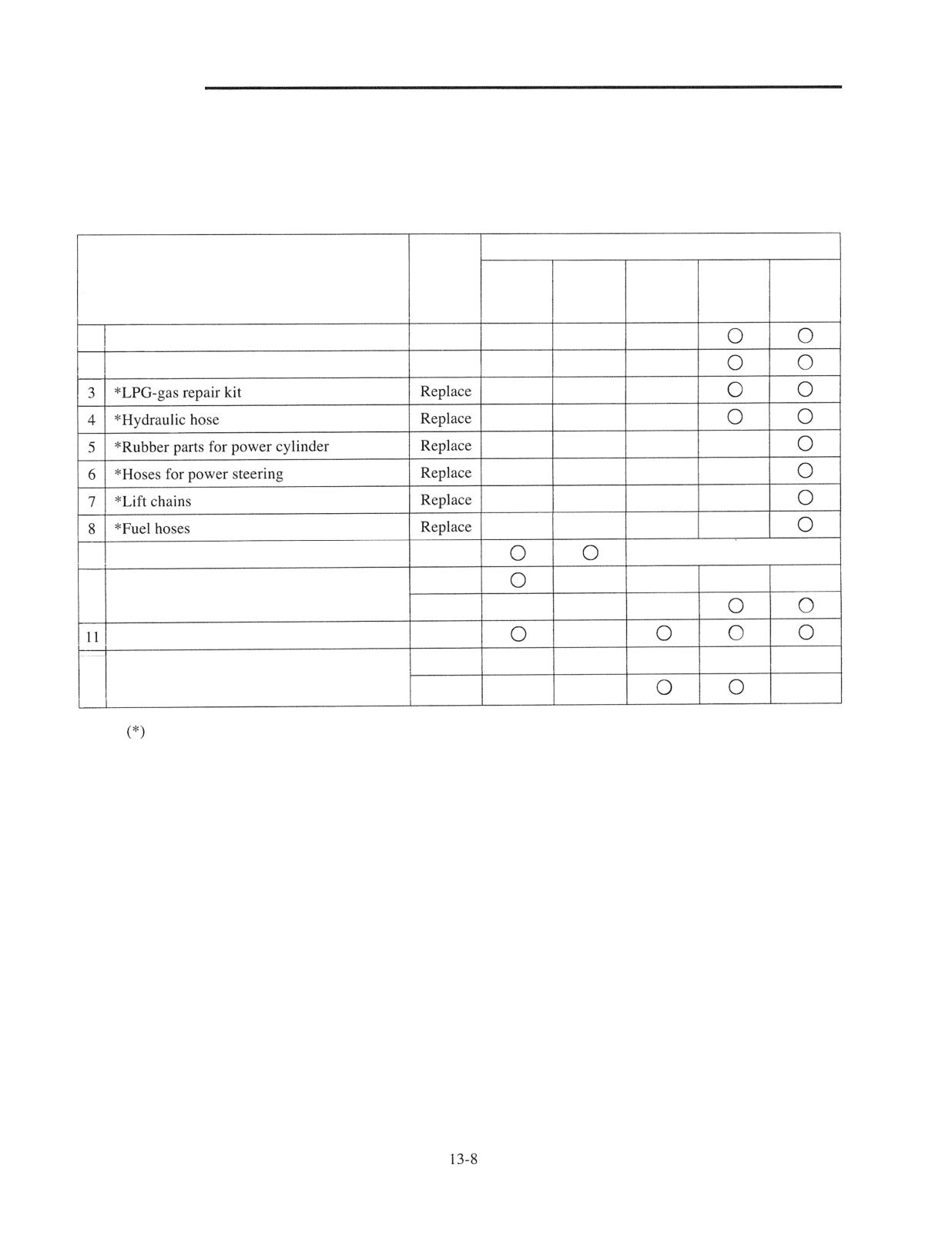
Periodic Replacement Parts
The parts listed below are important for the safe operation of the truck, and are specially designated as the parts to be
replaced at specified periods. Each service shop is requested to adhere to the replacement schedule given here on all
trucks brought into its care:
Period
1 month
Every
Every
Every
Every
Periodic replacement parts
Service
after
3 months
6 months
1 year
2 years
delivery
(500 hrs) (1000 hrs) (2000 hrs) (4000 hrs)
1 *Rubber parts for brake master cylinder
Replace
2 *Rubber parts for brake wheel cylinder
Replace
9 Engine oil filter element
Replace
every 3 months (500 hrs)
Clean
10 LPG fuel filter
Replace
Hydraulic tank return filter
Replace
Clean
12 Air clearance element
Replace
Note:
indicates important safety-related parts.
DATA
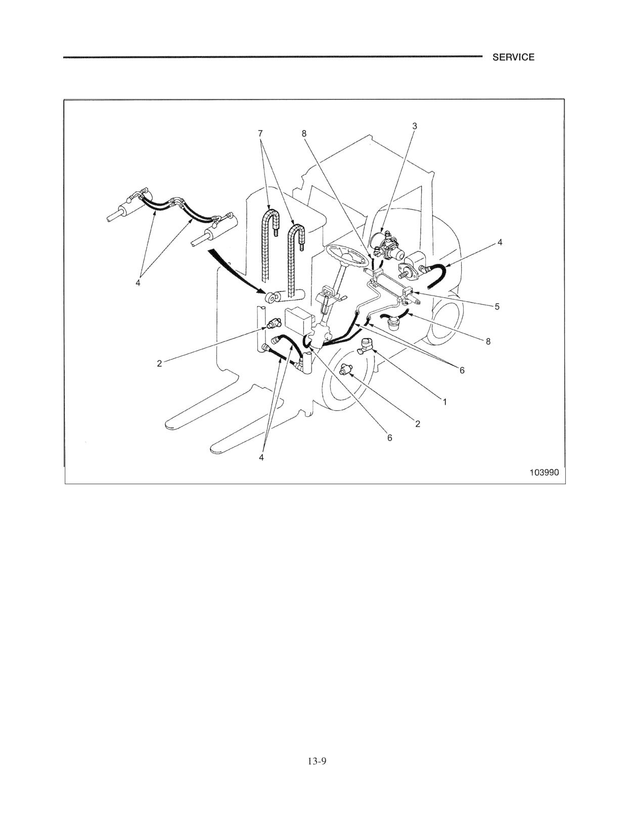
Location of Periodic Replacement Parts
SERVICE DATA
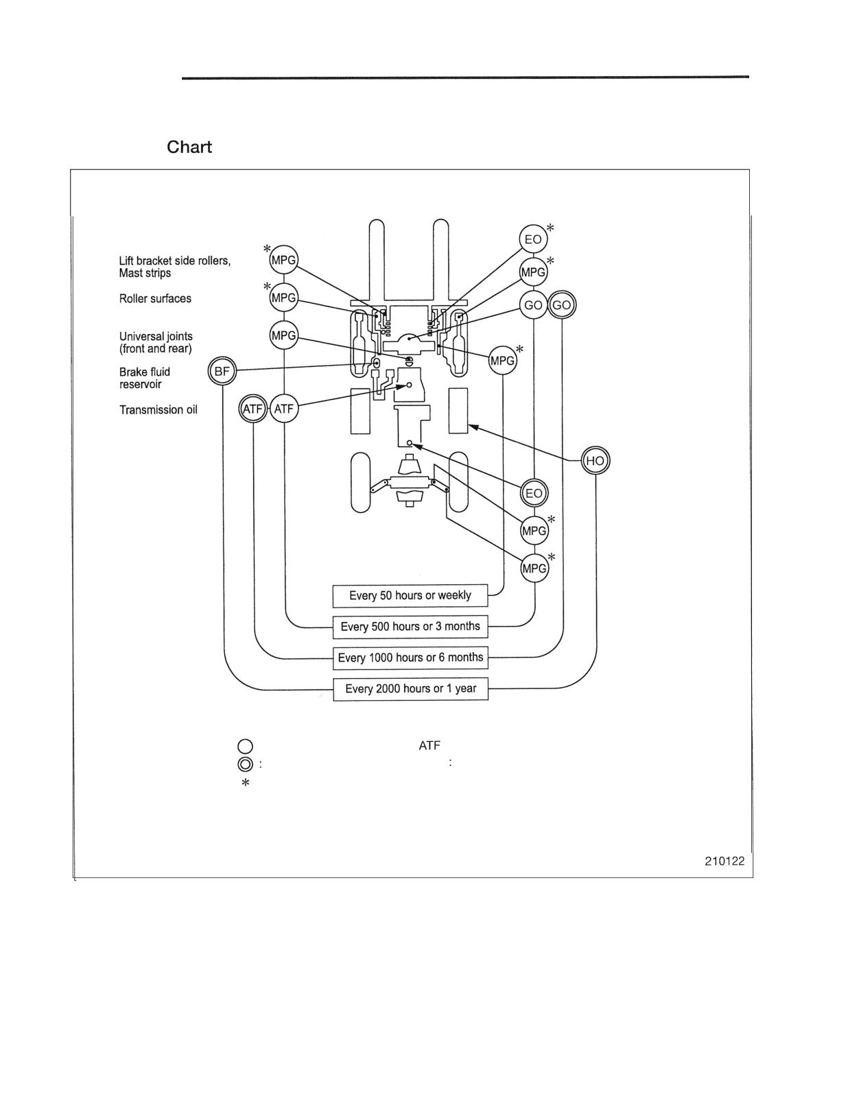
Lubrication Instructions
Lubrication
Lift chains
Tilt sockets
Transfer and
differential oil
Mast supports
Hydraulic oil
Engine oil
Tie rod pin
Kingpins
: Check and refill
: Torque converter oil
Change
MPG Multi-purpose grease
: Change
GO : Gear oil
EO
: Engine oil
BF
: Brake fruid
HO : Hydraulic oil
DATA
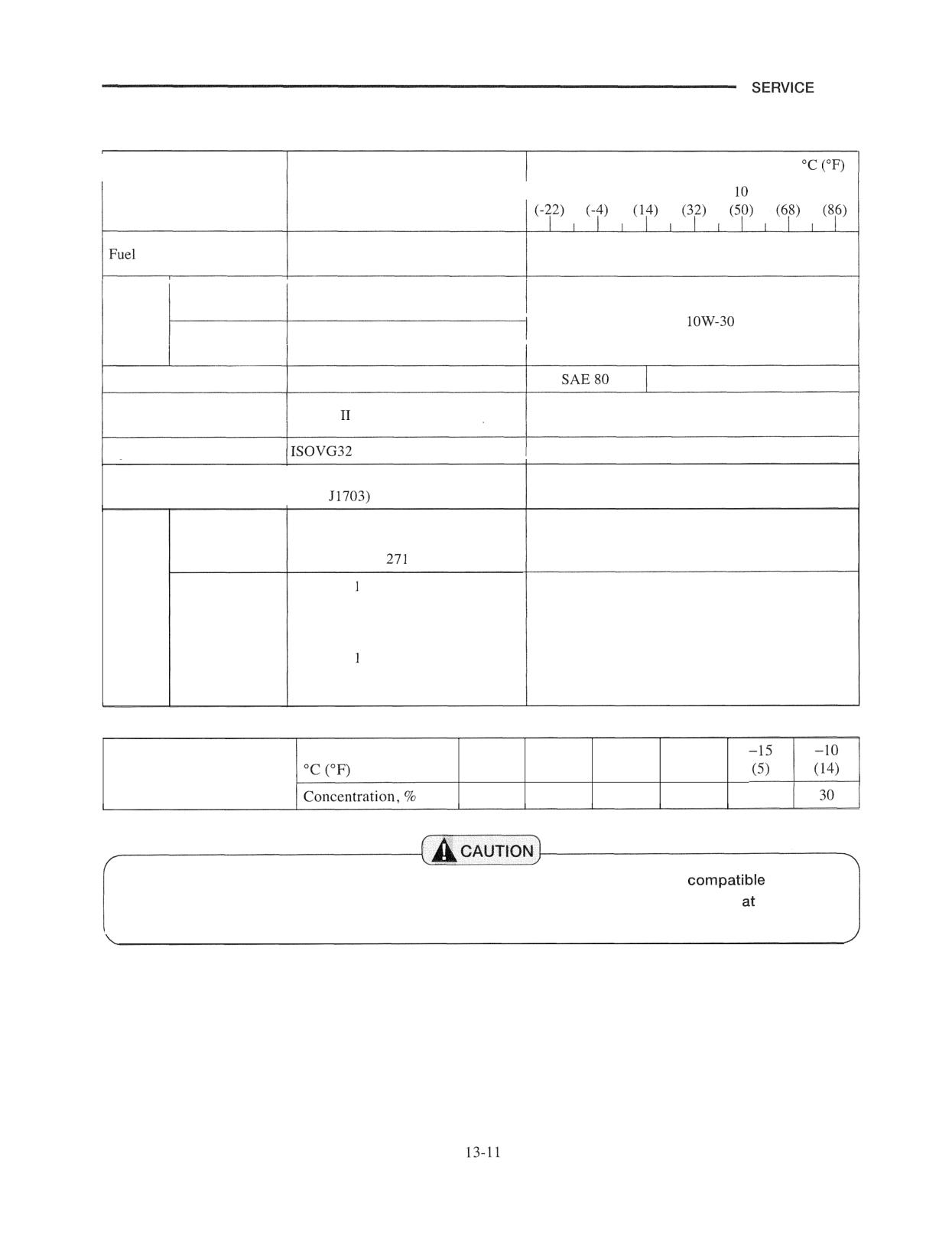
Fuel and Lubricant Specifications
Recommendation for ambient temperature
Fuel or lubricant
Specification
1-30
-20
-10
0
20
30
Consult your local Cat lift truck dealer
Gasoline-engine API service classification SJ
Engine
model
or above
SAE
oils
Diesel-engine
API service classification CF
model
or above
Transfer and differential oil GL-4 or GL-5
SAE 90
Powershift transmission oil Dexron
Consult your local Cat lift truck dealer
Hydraulic oil
FMVSS - DOT 3 or DOT 4
Brake fluid
(SAE
NLGI No.2 grade multi-purpose type
Wheel bearings
(lithium base),
Consistency:
NLGI No. grade multi-purpose type
Grease
(calcium base),
Consistency:
320
Chassis
or
NLGI No. grade multi-purpose type
(lithium base),
Consistency:
315
Ambient temperature,
- 39
- 30
- 25
- 20
Antifreeze solution
(- 38.2)
(- 22)
(- 13)
(-4)
(Long Lift Coolant)
5 5
50
45
40
35
Avoid mixing lubricants. In some cases, different brands of lubricants are not
with each
other and deteriorate when mixed. It is best to stick with one and the same brand
successive
service intervals.
SERVICE DATA
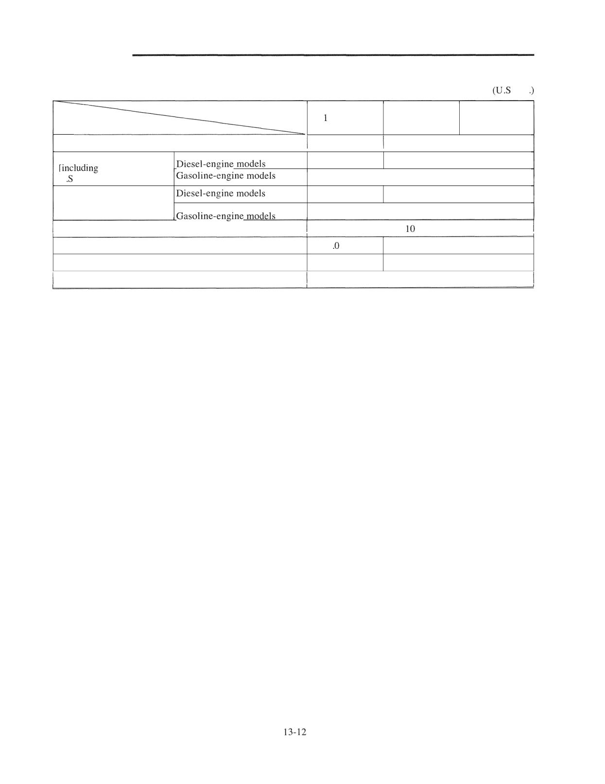
Refill Capacities
Unit: liter
. gal
Truck Models
ton class
2 ton class
3 ton class
Items
Fuel tank
53 (14.0)
76 (20.1)
Engine lubrication system
6.8
(1.8)
8.7
(2.3)
0.65 liter (0.17
U . gal.) for reserve tank]
7.4
(2.0)
Engine lubrication system
8.5
(2.2)
10 (2.6)
(including oil filter capacity)
3.8 (1.O)
Transmission oil
(2.6)
Differential gear oil
5
(1.3)
8.5
(2.2)
Hydraulic tank
28 (7.4)
39 (10.3)
Brake fluid reservoir
135 cc (8.2 cu in.)
SERVICE DATA
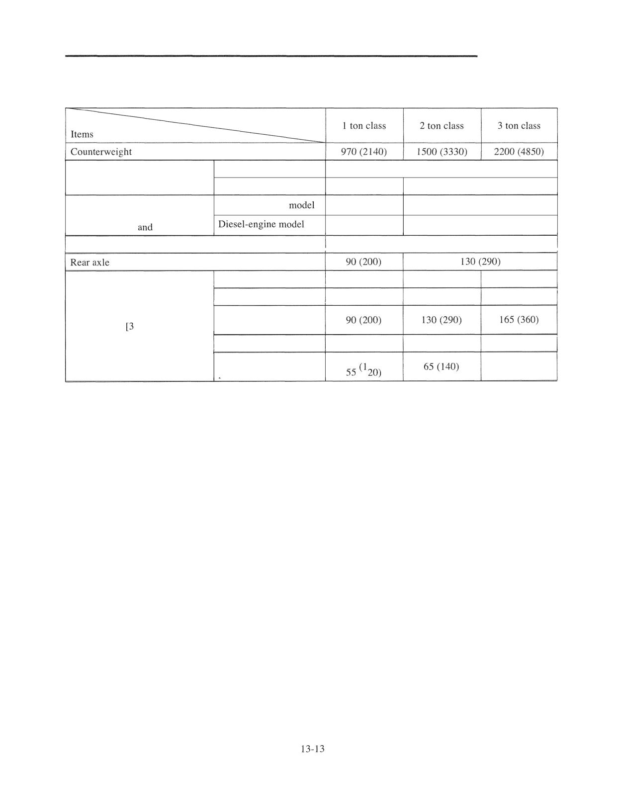
Weight of Major Components (Approximate)
Unit: kg (lb)
Truck Models
Gasoline-engine model
140 (300)
Engine service weight
Diesel-engine model
180 (400)
260 (570)
Power train
Gasoline-engine
280 (620)
290 (640)
Engine, transmission (excl.
reduction gear
differential)
350 (770)
395 (870)
Overhead guard
60 (130)
Outer mast
160 (350)
220 (485)
245 (540)
Inner mast
130 (290)
150 (330)
165 (360)
Lift bracket
Duplex mast m (118 in.)]
(incl. backrest)
Forks (two)
80 (180)
130 (290)
165 (360)
Lift cylinder and related
105 (230)
parts
Special
Tools
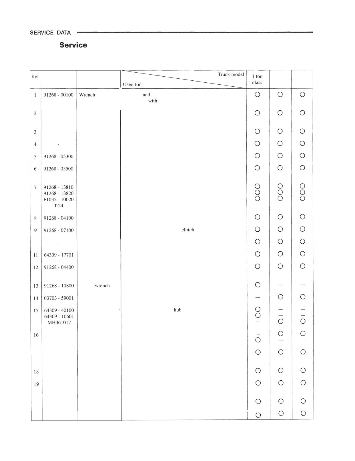
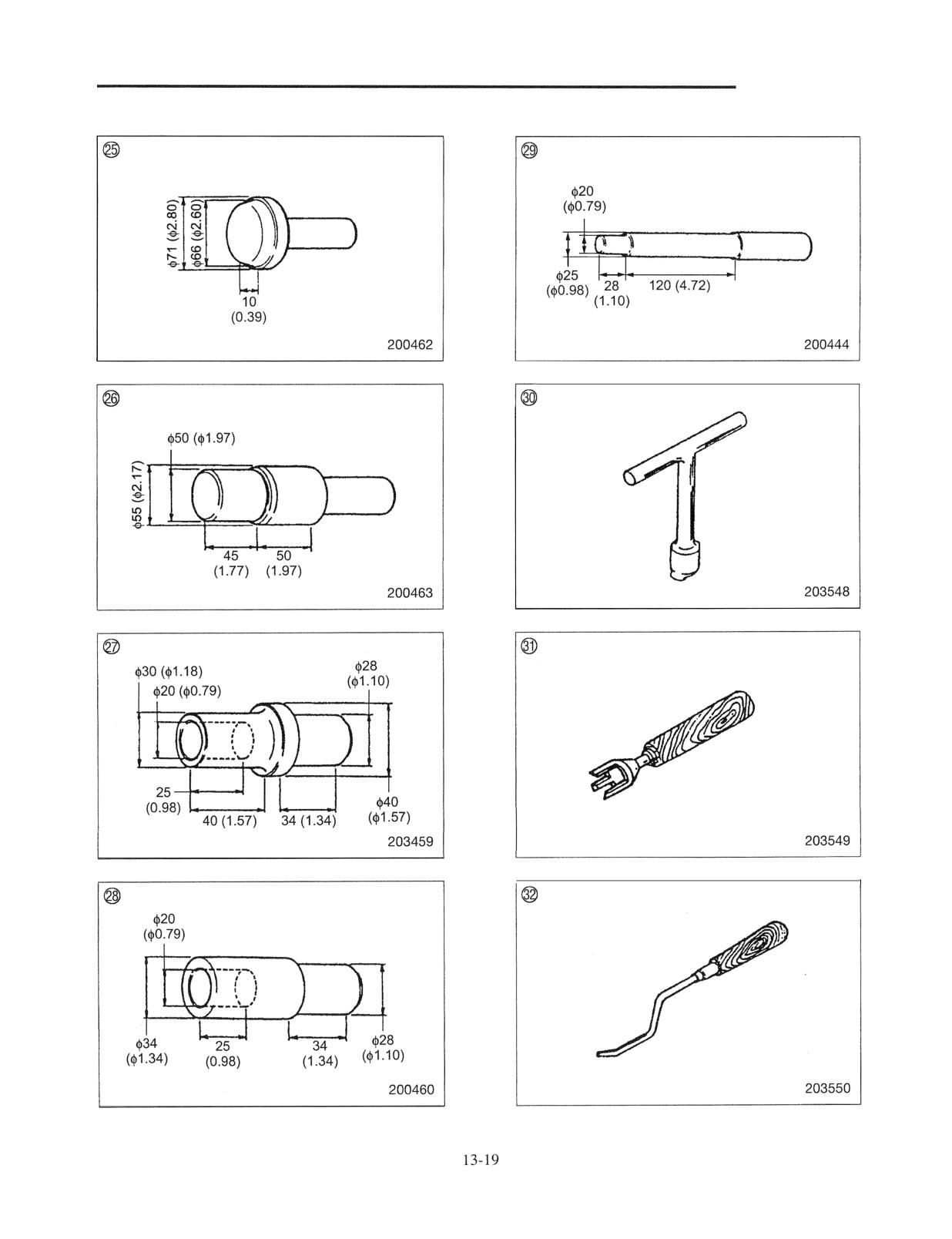
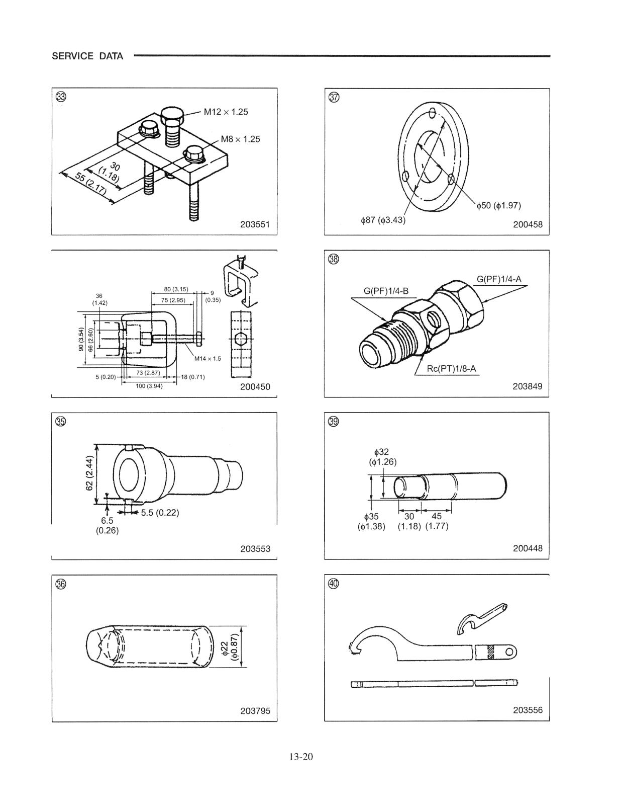
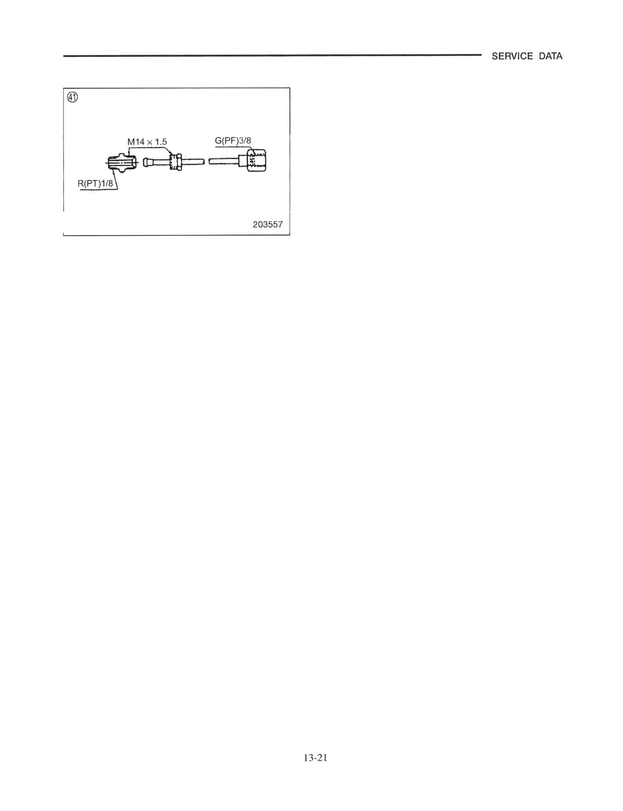
Special Service Tools
2 ton
3 ton
Part number
Part name
No.
class
class
1
91268 - 00100
Wrench
Removal
installation of pulley
(To be used
91 268 - 00200)
91268 - 00200
Wrench
Removal and installation of pulley
91868 - 00100
Wrench
91 268 - 00701
Socket wrench
Removal and installation of rear wheel nut and weight bolt
91268
05100
Bolt
Removal of pump body
Installer
Installation of pump body oil seal
Installer
Installation and tightening of transmission output shaft oil
seal
Puller
Removal of bearing
Plate
(To be used with plate, bolt and puller)
Bolt
(Commercially available, BANZAI)
Puller
Installer
Installation of ball bearing
Piston tool
Removal and installation of
return spring
10
91268
00500
Ring puller
Removal and installation of snap ring
Gauge kit
Measurement of transmission hydraulic pressure
Connector
Measurement of hydraulic pressure
(To be used with 64309 - 17701 Gauge kit)
Socket
Removal and installation of front wheel hub nut
Socket wrench
Removal and installation of front wheel hub nut
Bevel pinion puller
Removal of front wheel
Puller seat
Removal of front wheel hub
Wheel hub puller
Removal of front wheel hub
91468 - 00300
Installer
Installation of front axle wheel bearing inner race
64309 - 12300
Installer
17
91268 - 05400
Installer
Installation of oil seal into carrier cover input flange
differential carrier
91268 - 05600
Installer
Installation of bevel pinion taper roller bearing into
91268 - 05700
Installer
Installation of bevel pinion taper roller bearing into carrier
cover
20
91268 - 05800
Installer
Installation of bevel pinion taper roller bearing
21
91268 - 05900
Installer
Installation of drive gear ball bearing into carrier cover
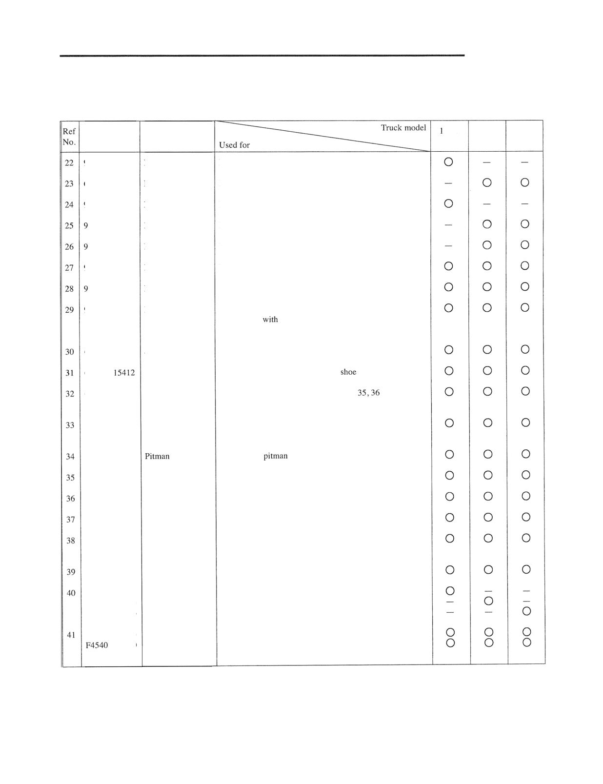
SERVICE DATA
ton
2 ton
3 ton
Part number
Part name
class
class
class
31268 - 01500
[nstaller
Installation of rear axle inner bearing inner race
54309 - 40400
Installer
Installation of rear axle inner bearing inner race
31268 - 01400
Installer
Installation of rear axle outer bearing inner race
1468 - 00400
[nstaller
Installation of rear axle outer bearing outer race
1468 - 00500
[nstaller
Press-fitting of rear axle pivot bushing
31468 - 00100
[nstaller
Installation of bell crank bearing and king pin bearing
1468 - 00200
Installer
Removal of bell crank bearing and king pin bearing
91268 - 01200
Installer
Removal and installation of king pin bearing
(To be used
91468 - 00100 and 91468 - 00200
Installers)
64309 - 15411
Spring remover
Removal of return spring
64309 -
Spring retainer
Removal and installation of brake
64309 - 15413
Spring hook
Installation of return spring (Tools No.
and 37 are
included in 64309 - 15400 Tool Set)
91268 - 10600
Steering wheel
Removal of steering wheel
puller
91268 - 01800
arm puller
Removal of
arm
91268 - 13400
Socket
Removal and installation of power cylinder guide
91268 - 13600
Rod cap
Insertion of power cylinder guide
91268 - 03300
Plate
Assembly of steering gear control valve
91268 - 06200
Connector
Measurement of power steering relief pressure
(To be used with 64309 - 17701 Gauge kit)
91268 - 01600
Installer
Installation of tilt Cylinder tube busing
09305 - 00680
Hook wrench
Removal and installation of tilt cylinder guide bushing
09305 - 00750
Hook wrench
Removal and installation of tilt cylinder guide bushing
09305 - 00880
Hook wrench
Removal and installation of tilt cylinder guide bushing
64309 - 16300
Pipe
Measurement of control valve main relief pressure and
- 06300
Connector
overload relief pressure
(To be used with 64309 - 17701 Gauge kit)
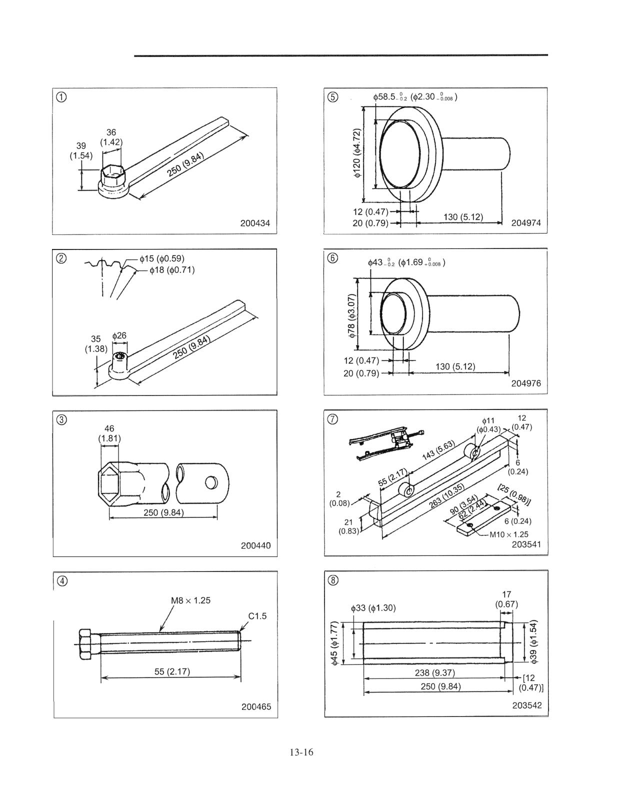
SERVICE DATA
Detail of splines
200435
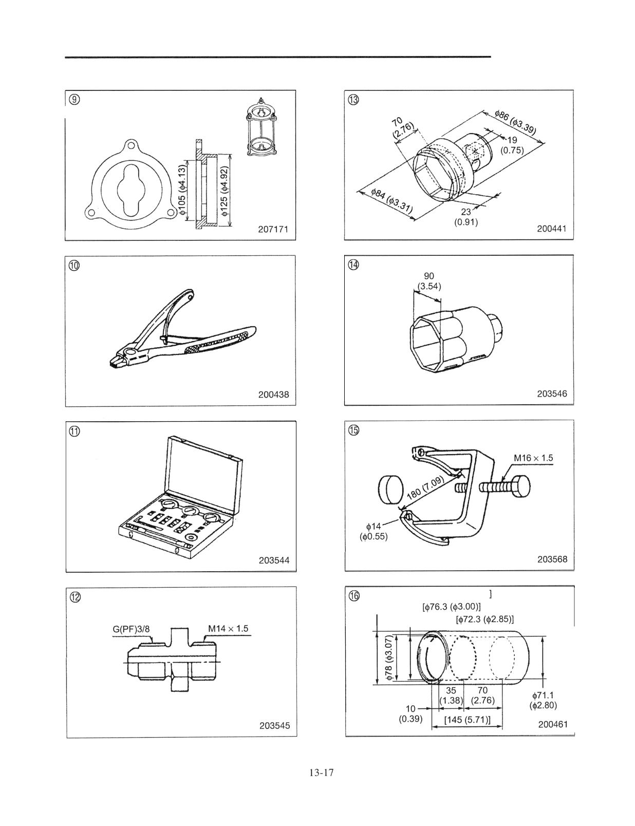
SERVICE DATA
Dimensions in [ are for 1 ton class
$89 ($3.50)
$76 ($2.99)
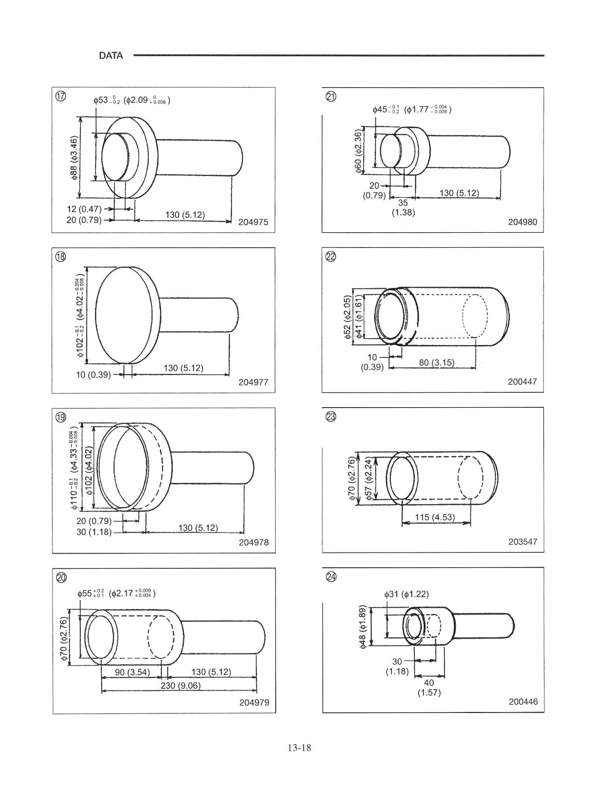
SERVICE
SERVICE DATA
TECHNICAL
Date:
Print)
Dealer
Submitted By:
Address:
P.O. Box:
City:
State:
Zip Code:
Country:
The following discrepancy or omission has been discovered in:
Operation Maintenance Manual
Option Bulletin
Part
Special Instructions
Service Manual
Service Data Manual
Electronic Manual
Other
Publication
Engine Model
Truck model
Issue date
Truck serial
Page
(Please Print)
of discrepancy or omission:
(Please fax or mail completed form to):
Mitsubishi Caterpillar Forklift America Inc.
Mitsubishi Caterpillar Forklift Europe B.V.
Attn: Technical Publications
Attn: Service Engineering
21 21 W. Sam Houston Parkway N.
Box 30171
Houston, Texas 77043-2305
1303 AC, Almere, The Netherlands
Fax: 713-365-1616
Fax: 31-36-5494-695
Mitsubishi Caterpillar Forklift Asia Pte. Ltd.
RCB No. 199203169H
Attn: Service Engineering
No. 2 Tuas Avenue 20
Singapore 638818
Republic of Singapore
Fax: 65-6861-9277