Clark GEX20-30 (RATED CAPACITY : 2000~3000kg). SERVICE MANUAL (2006) - page 3
Group 23, Brake System
Section 1
Brake System Specifications and Descriptions
Specifications
2
General Description
2
Service Brake Operation
2
Park Brake Operation
2
Service Requirements
2
SM 765, Nov ’06
Brake System Specifications and Descriptions • 23-1-1
Group 23, Brake System
Specifications
Service Brake Operation
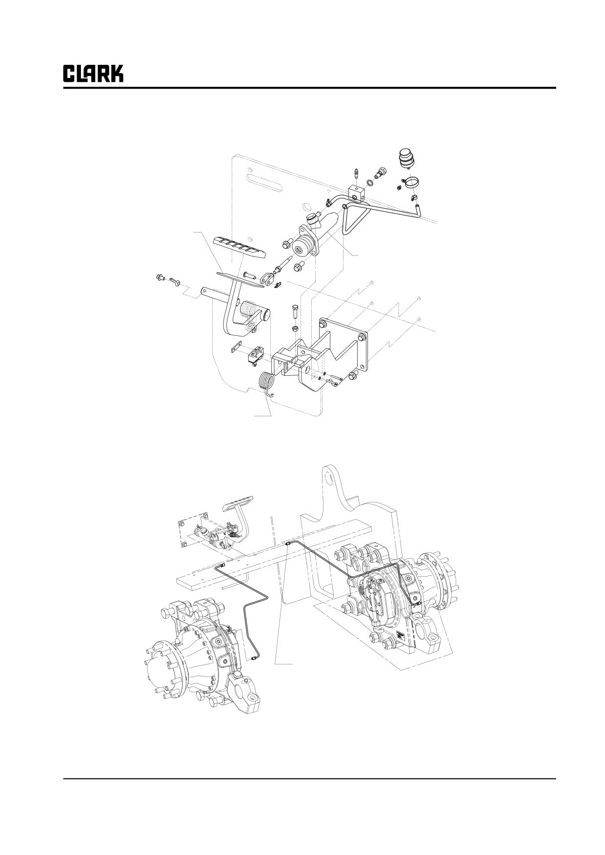
The Service brake pedal operates a master cylinder
Service Brake:
mounted on the front frame. The master cylinder operates
Type: Wet disc brake
a wheel cylinder. The wheel cylinder operates a shoe lin-
ings to be contacted on drum.
Fluid: Hydraulic fluid, RANDO HD32 or NUTO H32
in accordance with CLARK specification MS-68
(CLARK #2776239)
Parking Brake Operation
Pedal Freeplay: None
Operate the brake by pulling the hand brake mounted on
the battery hood. The depressed pedal tensions cables
Parking Brake:
connected to a brake shoe at each brake assembly, thereby
applying the brakes.
Type: Hand brake linked to service brake at each wheel.
Press the button on the front side of hand brake, then the
Holding Test: Rated load on 15 % grade.
parking brake will be released. This handle releases the
ratchet, and a return spring returns the pedal and cable to
the off position. The ratchet also operates the parking
brake interlock switch and the parking brake indicator
light switch.
General Description
Brake pedal linkage - A mechanical system through which
Service Requirements
the brake pedal operates the master cylinder.
Operational checks and inspection of linkage, brake lin-
Master cylinder - The pistons are activated by brake pedal
ing, and brake lines are specified in the Periodic Service
movement.
Chart in Group PS.
Brake lines - These lines carry the brake flow from the
Service brake linkage adjustment and lube are not nor-
master cylinder to the wheel cylinders.
mally required.
Service brake assembly - The drums, shoes and wheel cyl-
Brakes are self-adjusting and normally require no adjust-
inders.
ment.
Parking brake-Operates the service brake shoes via cables.
A leaking master cylinder should be overhauled or
See “Parking Brake Adjustment”, in this Group for
replaced.
details.
23-1-2 • Brake System Specifications and Descriptions
SM 765, Nov ’06
Group 23, Brake System
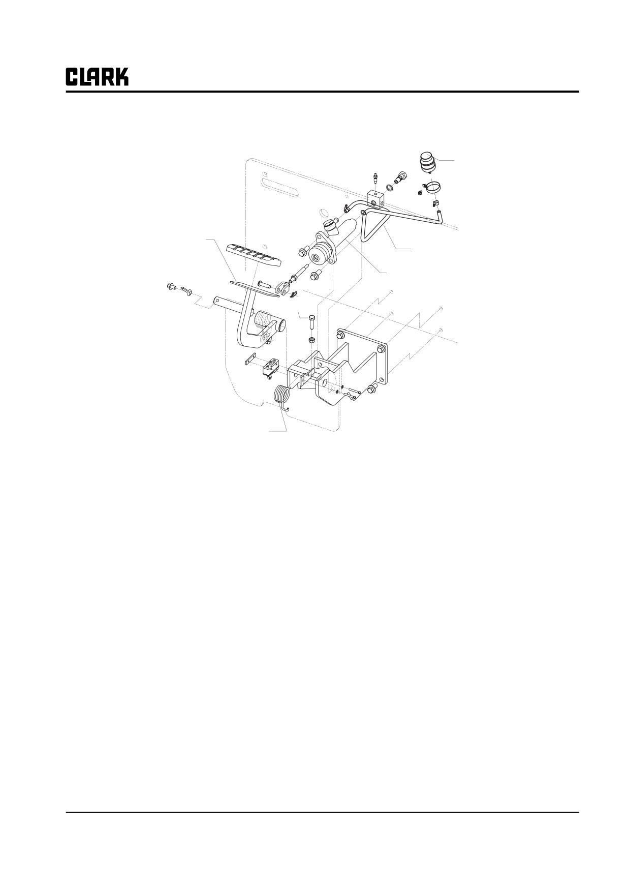
Brake lever &
Pedal
Master Cylinder
Return spring
Brake Line to
Master Cylinder
SM 765, Nov ’06
Brake System Specifications and Descriptions • 23-1-3
NOTE :
Group 23, Brake System
SM 765, Nov ’06
Group 23, Brake System
Section 2
Service Brake Troubleshooting
Service Brake Troubleshooting
2
SM 765, Sep ’06
Service Brake Troubleshooting • 23-2-1
Group 23, Brake System
Service Brake Troubleshooting
Causes/Corrective
Condition
Actions
Brake pedal drops to floor
A C E
Brake pedal spongy
A B
Brakes stick, drag excessively, make noise, or overheat
D E F
Excessive effort required to apply brake
A E
Causes/Corrective
Actions
A. External leak in wheel cylinder or other component of braking system
Inspect/replace/repair.
B. Air in braking system
Bleed and recheck.
C. Linkage broken or return spring damaged
Inspect/repair.
D. Brake master cylinder defective
Inspect/overhaul or replace.
E. Brake disc. worn or brakes misadjusted
Inspect/repair/adjust.
F. Parking brake misadjusted
Adjust.
23-2-2 • Service Brake Troubleshooting
SM 765, Sep ’06
Group 23, Brake System
Section 3
Brake Pedal Linkage & Adjustments
Introduction
2
Adjustment
2
SM 765, Nov ’06
Brake Pedal Linkage & Adjustments • 23-3-1
Group 23, Brake System
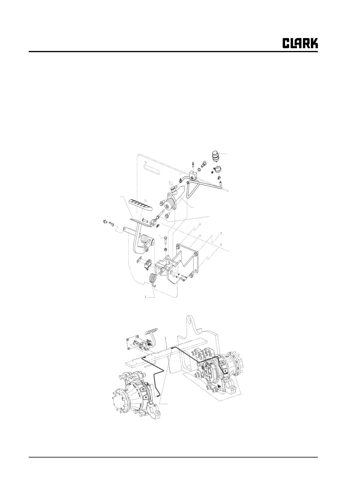
If you want to adjust the height of brake pedal, adjust the
Introduction
height as 25mm by use of stop bolts of brake pedal and
The illustration shows the service brake linkage which
then lock the nuts.
links the brake pedal to the master cylinder.
Tighten the stop bolts and nuts with torque of
20-
25N.m(14-18 ft.lb).
Adjustment
Adjust the master cylinder push rod assembly to eliminate
any slack in the pedal linkage. Adjust only the minimum
required to remove pedal play.
Brake Reservoir
Brake Lever &
Pedal
Master Cylinder
Jam Nut &
Push Rod Assembly
Stop Bolt
Return Spring
Brake Line to
Master Cylinder
23-3-2 • Brake Pedal Linkage & Adjustments
SM 765, Nov ’06
Group 23, Brake System
SM 765, Nov ’06
Brake Pedal Linkage & Adjustments • 23-3-3
NOTE :
Group 23, Brake System
SM 765, Nov ’06
Group 23, Brake System
Section 4
Brake Bleeding
Bleed brakes when:
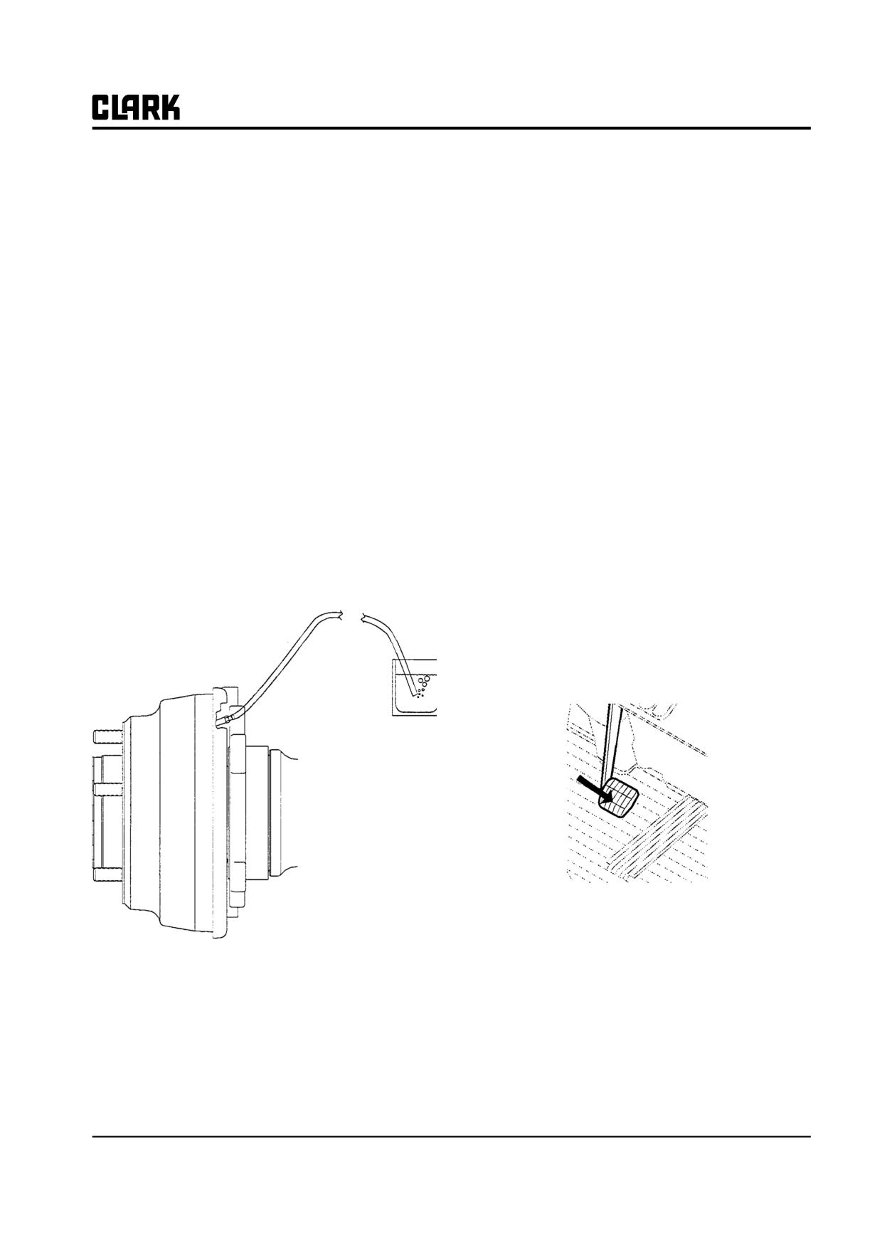
3. Attach a clear hose to a bleed screw on one of the
brake cylinders. Place the other end of the hose in a
• The brake pedal feels spongy.
jar containing Hydraulic fluid, RANDO HD32 or
• The brake master cylinder or wheel cylinders-or
NUTO H32
lines between-have been leaking and/or have been
in accordance with CLARK specification MS-68
repaired or replaced.
(CLARK #2776239).
• Troubleshooting otherwise indicates that air has
4. Open the bleed screw.
been introduced into the system.
5. Depress the brake pedal and watch fluid flow into the
Bleed the brakes as follows:
jar. When the fluid appears to be free of bubbles,
tighten the bleed screw, then release the pedal.
1. Park truck on level floor. Put direction control in neu-
tral. Lower forks to floor, tilt forward, and apply
6. Check the fluid in the brake reservoir. Refill as
parking brake.
required.
2. Remove cap from the brake reservoir to be sure it is
7. Release the parking brake and operate the brake
full of fluid.
pedal. If the brake pedal does not come up or still
feels spongy, bleed the system again.
SM 765, Nov ’06
Brake Bleeding • 23-4-1
NOTE :
Group 23, Brake System
SM 765, Nov ’06
Group 23, Brake System
Section 5
Pedal and Master Cylinder Service
(Removal, Replacement, and Adjustment)
SM 765, Nov ’06
Pedal and Master Cylinder Service (Removal, Replacement, and Adjustment) • 23-5-1
Group 23, Brake System
Components Disassembly
Freeplay Adjustment
Use Figures 1, 2, and 3 as guide to disassembly and
When the brake pedal linkage is properly adjusted, brak-
adjustment.
ing should begin only after the pedal is depressed a certain
distance, This is “Freeplay” is Adjusted as follows :
Components Reassembly
1. Loosen the jam nut on the rod brake master cylinder
(Figure 1).
Replace the brake pedal components as shown in Figures
1 and 2 using fastener torques where shown. Also use the
2. Depress the brake pedal 4~6mm (0.16~0.24 in).
following notes:
3. Adjust the rod until you feel the push rod make clear-
1. Clean the reservoir and master cylinder hoses and fit-
ance with the cylinder piston.
tings. Make sure no contaminants enter the braking
system.
2. Adjust pedal free play as described in “Pedal Adjust-
ment” on the page.
3. After re-assembly and adjustment, the brake system
must be bled, see Section 2 in this Group. After
bleeding, check all fluid connections for leaks and
test brakes completely before returning truck to ser-
vice.
23-5-2 • Pedal and Master Cylinder Service (Removal, Replacement, and Adjustment)
SM 765, Nov ’06
Group 23, Brake System
Reservoir
Brake Lever &
Hose to Master Cylinder
Pedal
Master Cylinder
Stop Screw
Pedal Spring
SM 765, Nov ’06
Pedal and Master Cylinder Service (Removal, Replacement, and Adjustment) • 23-5-3
NOTE :
Group 23, Brake System
SM 765, Nov ’06
Group 23, Brake System
Section 6
Parking Brake Service
Operation
2. Actuate and release pedal six to eight times.
3. Readjust and tighten nuts.
Operate the brake by pulling the hand brake mounted on
the battery hood. The pulled hand lever tensions cables
connected to a brake shoe at each brake assembly, thereby
Removal and Replacement
applying the brakes.
As shown in illustration below, with these notes:
Press the button on the front side of hand brake, then the
parking brake will be released. This handle releases the
• Adjust position of interlock and indicator switches
ratchet, and a return spring returns the pedal and cable to
with pedal upstop against tab on bracket. Switch
the off position. The ratchet also operates the parking
contacts should snap from their operated contact
brake interlock switch and the parking brake indicator
position to their normal position when pedal is
light switch.
depressed one ratchet click.
• Torque switch mounting nuts 0.8-1.0 N⋅m (7-9
lbf⋅in). Torque bracket mounting nuts 20-23 N⋅m
Adjustment
(177-210 lbf⋅in).
1. With the lever fully lower, upstop against tab on
• Apply a thin coat of Clark lubricant, part
bracket, adjust slack out of brake cables and tighten
#1802155, to ratchet teeth and ball end of wire
adjusting/locking nuts.
rope prior to assembly.
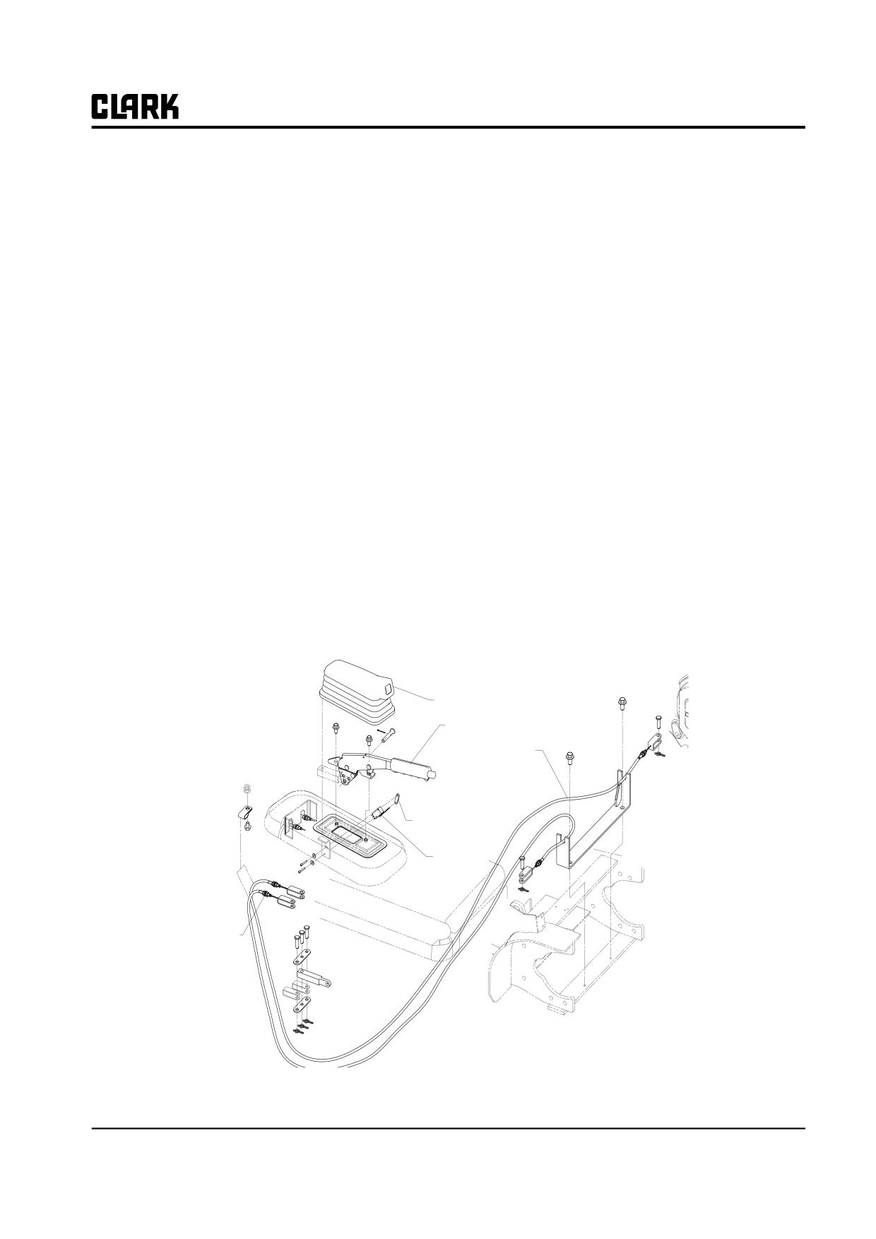
Parking Brake handle Boot
Parking Brake handle
Parking Brake Cable
Switch Mounting Plate
Switch
Adjusting/
Locking Nuts
SM 765, Sep ’06
Parking Brake Service • 23-6-1
Group 23, Brake System
2. Remove the parking cable from the service brake
Parking Brake Cable Removal and
assembly by first removing the brake shoes as
Installation
described in the “Brake Overhaul and Adjustment”
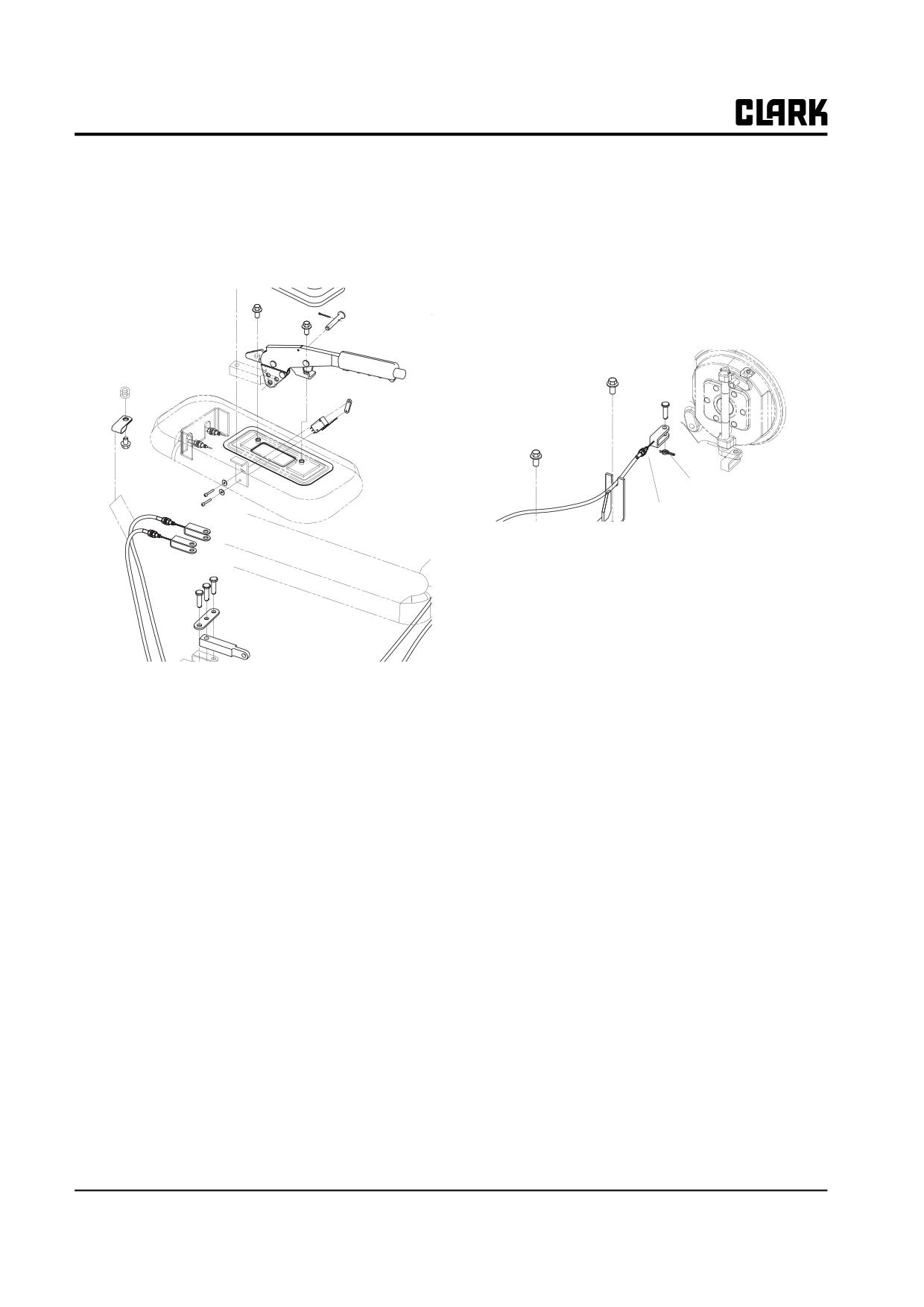
1. Disconnect each parking brake cable from the ratchet
Section of this Group.
assembly as shown in the illustration below.
3. Pull out the C-clip that holds the parking brake cable
to the backing plate.
4. Unhook the parking brake cable end from the lever
on the shoe and pull the cable from the assembly.
Pin
Lock Nut
5. Installation is the reverse of removal.
23-6-2 • Parking Brake Service
SM 765, Sep ’06
GROUP 25
GROUP 25
STEERING COLUMN AND GEAR
Steering System Specifications and Description . Section 1
Steering System Troubleshooting
Section 2
Steering Column Removal and Installation
Section 3
Steering System Relief Pressure Check
and Adjustment
Section 4
Steering Gear Overhaul
Section 5
SM 765, Nov ’06
Group 25, Steering Column and gear
NOTE :
Group 25, Steering Column and gear
SM 765, Nov ’06
Group 25, Steering Column and Gear
Section 1
Steering System Specifications and Description
Specifications
Description
Steering System Type: Hydrostatic power steering with
All truck models have a hydrostatic power steering sys-
load sensing, dynamic signal neutral circuit.
tem, which is supplied with oil pressure from the main
hydraulic pump. The steering hand wheel operates the
Steering System Relief Pressure Setting: 10000 kPa (1450
steering gear (steering control unit), which directs oil flow
psi)
to the steering cylinder on the steer axle. A steering sys-
tem pressure relief valve is built into the steering control
unit to prevent over-pressurization of the steering system.
The pressure relief setting can be tested by installing a test
Service Intervals
fitting install Quadrigage at pressure inlet of steering gear.
Check the steering system relief pressure annually or after
The power steering gear is a remote positioning control
every 2000 hours of operation. Make a visual inspection
valve that senses the input signal from the steering hand
of steering control unit hydraulic fittings periodically to
wheel, multiplies this signal to assist in reducing the steer-
ensure that the fittings are tight with no leakage.
ing effort, and causes the steering axle to turn the wheels
to the desired position by supplying hydraulic flow to the
Fastener Torques
steering cylinder.
The steering gear is connected to the bottom of the steer-
Steering Handwheel Nut: 35-45 N⋅m (25.5-33.5 ft-lb)
ing column. When the steering hand wheel is turned, it is
linked mechanically to the steering gear spool and causes
this spool valve to shift from its closed neutral position to
a “turn” position that allows oil under pressure to flow to
the steering cylinder.
When the steering hand wheel stops turning, centering
springs in the valve automatically center the spool, stop-
ping the flow of oil to the cylinder.
The low pressure oil from the opposite side of the steering
cylinder is returned through the opposite port in the gear.
It is controlled by the same spool as the high pressure
port.
In the event of a pump failure, the steering gear can gener-
ate sufficient hydraulic power by movement of the steer-
ing handwheel to serve as a limited steering method. An
internal check valve automatically closes to divert this
generated oil flow to the proper port of the steering cylin-
der. The handwheel turning effort is considerably higher,
however, than with power steering.
SM 765, Nov ’06
Steering System Specifications and Description • 25-1-1
Group 25, Steering Column and Gear
The column tilt lock mechanism allows the operator to
The cover can be removed for service to steering column
adjust the steering column. The column tilt lever knob
components. The entire column can be removed for ser-
releases the adjustment setting and the column returns to
vice or replacement.
the up position by the use of gas springs. The tilt lock
mechanism, the directional control lever are protected by
the steering column cover.
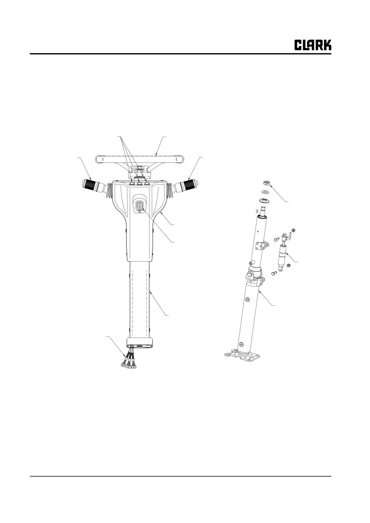
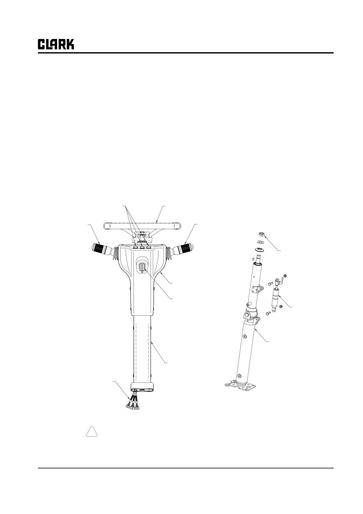
Locker Switch
Steer Handle
Direction Control
Light Switch Lever
Assembly
Steer Handle
Screw
Column Upper Cover
Tilt Lock Lever
Gas Spring
Tilt Lock Assembly
Column Lower Cover
Wire Harness
Column Outside
Column Inside
25-1-2 • Steering System Specifications and Description
SM 765, Nov ’06
Group 25, Steering Column and Gear
Section 2
Steering System Troubleshooting
No steering
Handwheel kickback
• Hydraulic fluid level very low.
• Check valve faulty (or not in system).
• Air in hydraulic oil.
Slow steering response
• Steering column sections not connected properly.
• Hose broken.
• Oil viscosity too high.
• Hydraulic pump contaminated or defective.
• Contaminated or defective steering gear.
• Priority valve spool stuck.
Chatter conditions
Hard steering
• Loose mountings or linkage. Make certain all
• Hydraulic fluid level low.
mounting fasteners and other linkage is tight.
• Air in hydraulic oil.
• Pressure relief valve set too low and is out of
adjustment; adjust or replace the relief valve.
• Steering gear contaminated or defective.
• Insufficient pump flow. Check pump for leaks and
• Relief valve setting too low; adjust or replace.
see Section 5 of this Group.
• System leaking.
• Axle load too heavy.
Unsatisfactory steering in either direction
• Lack of lubrication.
• Air in system due to excessive wear in steering cyl-
• Defective steering gear.
inder. Check for air in system. Excessive noise or
• Spring in priority valve broken.
foamy condition of hydraulic fluid indicates aera-
tion. Check that air is not entering the system
High number of handwheel turns
through poor threads, cracked, split, or worn hoses,
bad pump seals, bad O-rings, bad gaskets, or loose
• Steering cylinder seal leakage.
connections.
• Worn steering gear.
Worn cylinders result in leakage past the piston.
Overhaul (see Group 26, Section 6) or replace the
Steering handwheel spins freely
steer cylinder.
• Air in system (cavitation).
• Incorrect system pressure due to worn pump.
• Low oil supply.
Replace the relief valve or repair or replace the
hydraulic pump.
• Steering column detached from steering gear.
• Defective steering gear.
Noise during turns
Jerky steering
• Worn bearing(s) in steering arm; replace bearings.
• Worn pin in steering knuckle; replace pin.
• Steering gear malfunction because of worn parts or
contamination. Steering gear may require over-
• Worn bearings in steering knuckle; replace bear-
haul.
ings.
• Steering knuckle is loose; tighten castle nut.
Truck turns in wrong direction
• Hydraulic lines not installed correctly.
SM 765, Nov ’06
Steering System Troubleshooting • 25-2-1
Group 25, Steering Column and Gear
Constant noise from steering axle
Low pressure at the steering gear
• Loose or worn hub bearing cones. Adjust or
• Refer to Group 26.
replace hub bearing cones. Replace bearing cones
and bearing cups as a set.
Steer cylinder rod binding or sticking
• Binding of linkage. With hydraulic flow shut off
Noise when axle pivots
from the cylinder and the rod end uncoupled, the
• Steering axle mountings worn; replace mountings.
rod should slide freely in or out by hand. If the pis-
ton is binding, overhaul or replace the cylinder.
• Steering axle mounting cap(s) loose; tighten
mounting cap(s).
Fluctuating pressure
• Faulty operation of relief valve. Fluctuating pres-
sure or loss of pressure in the system is usually
caused by scales, chips, sludge, or filings that have
lodged between the relief valve and seat. A dam-
aged spring or worn valve may also be the cause of
the trouble. Flush and refill the system and replace
the hydraulic return line filter element.
25-2-2 • Steering System Troubleshooting
SM 765, Nov ’06
Group 25, Steering Column and Gear
Section 3
Steering Column and Component Removal and Replacement
Steering Column and Component Removal
2
Key Switch Removal
2
Hand Wheel, Horn Contact Ring, and Directional Control Assembly Removal
2
Column Tilt Lock Assembly Removal
2
Steering Gear and Lower Steering Column Removal
3
Steering Column and Component Replacement
4
IMPORTANT
Before removing any component for overhaul, make sure the
correct repair parts, seals, and gasket sets are available.
Rocker Switch
Steer Handle
Direction Control
Light Switch Lever
Assembly
Steer Handle
Screw
Column Upper Cover
Tilt Lock Lever
Gas Spring
Tilt Lock Assembly
Column Lower Cover
Wire Harness
Column Inside
Column Inside
Typical Steering Column Assembly
! CAUTION
SAFE PARKING. Before working on truck:
SM 765, Dec ’06
Steering Column and Component Removal and Replacement • 25-3-1
Group 25, Steering Column and Gear
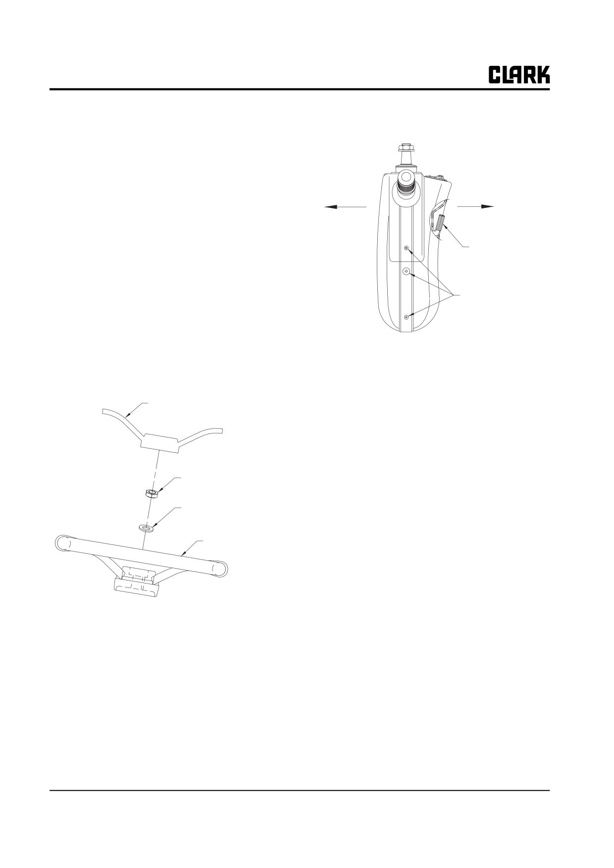
1. Park truck on a hard, level, and solid
switch and pull rear cover smoothly after removing
surface, such as a concrete floor with no
tilt lock leveler.
gaps or breaks.
2. Put upright in vertical position and fully
lower the forks or attachment.
3. Put all controls in neutral. Turn key
switch OFF and remove key.
4. Apply the parking brake and block the
wheels.
Tilt Lock Lever
Steering Column and Component
Removal
Determine which component requires service and check
Cover Screw
the procedure for removing that component. Read the pro-
cedure completely before beginning disassembly.
Hand Wheel, Light Switch Lever, and
NOTE
Directional Control Assembly Removal
Use care when removing the backside cover
as the rocker switch wiring is attached.
1. Disconnect the battery.
4. Disconnect wire connector assembled to direciton
Steer Handle Cover
control lever and light switch lever and remove direc-
tion control lever and light switch lever from steering
column by releasing two (+) screw.
Column Tilt Lock Assembly Removal
Steer Handle Screw
NOTE
The tilt lock assembly is not serviceable; only
Steer Handle Washer
the gas springs are serviceable. The tilt lock
assembly should be removed only for replace-
Steer Handle
ment as a complete assembly.
1. Remove the negative cable of battery.
2. Refer to "Handle, light switch lever and direction
control assembly removal" to remove upper cover.
2. Remove a hand cover and release nut and washer
3. Use (+) drive to remove 4 screws secruing lower col-
securing handle to steering column.
umn lever and then lower cover.
3. Remove 8 screws secruing both column cover using
(+) driver. Disconnect connector assembled on locker
25-3-2 • Steering Column and Component Removal and Replacement
SM 765, Dec ’06
Group 25, Steering Column and Gear
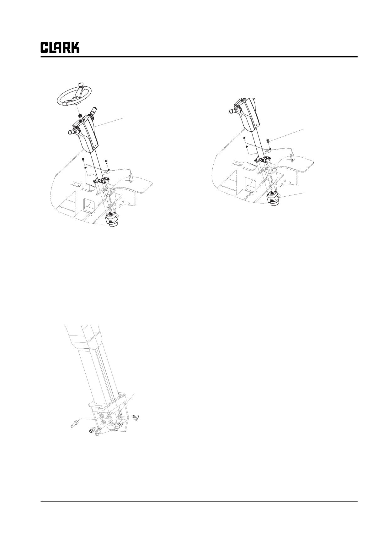
4. Remove 4 bolts secruing tilt assembly to frame. .
2. Remove the four bolts securing the lower column
shaft and steering gear to the bracket on the frame.
Tilt Lock Assembly
Mounting Screw
Steering Gear
3. Remove the lower shaft and steering gear assembly
from the truck.
Steering Gear Removal
1. Put a pan under the truck to catch hydraulic fluid
which will drip when fittings are loosened. Label the
four hose fittings of the steering gear to make sure
they are reassembled correctly. Loosen and remove
the hydraulic fittings at the steering gear. Cap the
ends to prevent fluid leaks. Cap the steering gear
ports to prevent dust and debris from getting into the
steering gear. Keep hydraulic ports and hoses clean.
Steering Gear
SM 765, Dec ’06
Steering Column and Component Removal and Replacement • 25-3-3
Group 25, Steering Column and Gear
Steer Column and Component
Replacement
These steps cover the procedures for reinstallation of the
steering column including the steering gear, the tilt lock
assembly, directional control assembly, ignition switch,
and steering hand wheel and horn.
IMPORTANT
Make sure all parts are clean and dry before
reassembling.
It may be necessary to assemble the steering
column in place and hand tighten fittings so
that the correct alignment of the entire col-
umn and parts can be checked. Once you
have the correct alignment, torque all fittings
to their correct specifications.
1. Component replacement and reassembly is in reverse
order of removal.
25-3-4 • Steering Column and Component Removal and Replacement
SM 765, Dec ’06
Group 25, Steering Column and Gear
Section 4
Stering System Relief Pressure Check and Adjustment
! CAUTION
!
WARNING
SAFE PARKING. Before working on truck:
Do not use your hands to check for hydraulic
leakage. Use a piece of cardboard or paper to
1. Park truck on a hard, level, and solid
search for leaks. Escaping fluid under pres-
surface, such as a concrete floor with no
sure can penetrate the skin causing serious
gaps or breaks.
injury. Relieve pressure before disconnecting
hydraulic or other lines. Tighten all connec-
2. Put upright in vertical position and fully
tions before applying pressure. Keep hands
lower the forks or attachment.
and body away from pinholes and nozzles
3. Put all controls in neutral. Turn key
which eject fluids under high pressure.
switch OFF and remove key.
If any fluid is injected into the skin, it must
be surgically removed within a few hours by
4. Apply the parking brake and block the
a doctor familiar with this type of injury or
wheels.
gangrene may result.
Description and Operation
Steering System Relief Pressure Setting
Steering system relief pressure settings above the speci-
Check and Adjustment
fied values can cause failure of the hydraulic lines, dam-
age to seals in the steering gear, and ball joint breakage on
This procedure requires installation of a pressure gauge at
the steer axle.
the gauge port on the main hydraulic pump. The pressure
is measured while the steering handwheel is turned fully
The steering system’s pressure relief valve is part of the
in one direction to put the steering system in bypass.
main hydraulic pump assembly. Steering system relief
pressure is adjustable and should be checked if indicated
Steering system relief pressure setting may be checked
by troubleshooting. Use the gauge port on the pump to
using a Mico Quadrigage (Clark Part No. 1800106) or
check steering relief pressure.
with a conventional pressure gauge, 0-20,700 kPa (0-3000
psi).
Steering system relief pressure setting should be 10000
kPa (1450 psi).
1. Tilt the steering column fully forward and raise the
seat deck.
NOTE
If relief pressure is not correct, the problem
may be caused by dirt in the valve or worn
parts, including steering control valve and
main hydraulic pump. Generally, if the relief
pressure measured when the steering system
is in bypass is not correct, the priority
demand valve should be replaced.
SM 765, Dec ’06
Stering System Relief Pressure Check and Adjustment • 25-4-1
Group 25, Steering Column and Gear
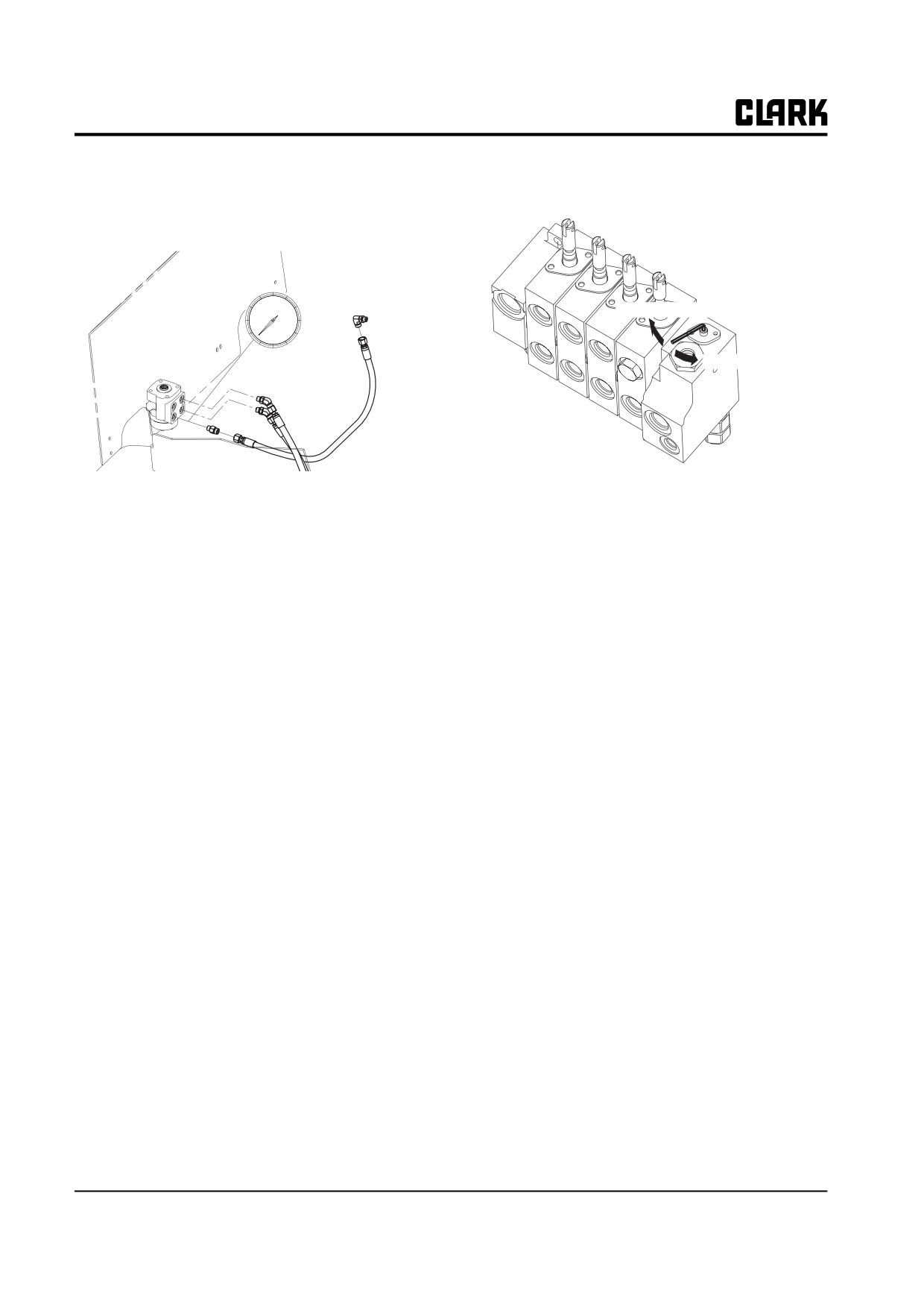
2. Clean the port opening and connect the pressure
gauge (also cleaned) to the gauge port on the main
pump.
To increase
To decrease
b. Clockwise adjustment of the relief valve seat
3. Start the engine and let it warm up until it runs
raises the pressure setting at which the valve
smoothly.
relieves pressure ; counterclockwise adjustments
4. Check steering system relief pressure setting at full
lowers the pressure setting at which the valve
throttle. Accelerate engine to full throttle and hold at
relieves pressure.
this speed while taking the pressure readings.
7. Restart engine and repeat steps to read and adjust the
IMPORTANT
relief pressure setting until correct relief pressure is
Do not operate system over relief any longer
set.
than required to read the pressure gauge.
• Once you adjust to the correct relief pressure set-
Prolonged time at relief pressure can result in
ting, reset the core plug in the valve bore.
a damaged pump and valve.
• If the correct relief pressure cannot be gained, con-
sider overhauling or replacing both the priority
5. Turn the steering handwheel in one direction until
valve and the pressure relief valve. See Group 29,
steering cylinder reaches its stop (relief bypass).
“Hydraulic Pump Overhaul” for instruction to
Hold steering handwheel in relief position until pres-
remove, overhaul, and replace the valves on the
sure reading is taken, and then release. Turn off
pump.
engine. Pressure should read between 10000 kPa
(1450 psi).
8. Disconnect the pressure gauge and close the engine
compartment.
6. To adjust the steering pressure relief to 10000 kPa
(1450 psi).
a. Carefully remove the core plug of the steering
pressure relief valve on the main pump by prying
the plug out.
25-4-2 • Stering System Relief Pressure Check and Adjustment
SM 765, Dec ’06
Group 25, Steering Column and Gear
Section 5
Steering Gear Overhaul
IMPORTANT
Before removing any component for overhaul, make sure the
correct repair parts, seals, and gasket sets are available.
NOTE
The following material does not show the load sensing port
on the steering gear (steering control unit). The port is
located in the center of the other four ports. The load sensing
port requires no special overhaul procedures.
SM 765, Dec ’06
Steering Gear Overhaul • 25-5-1
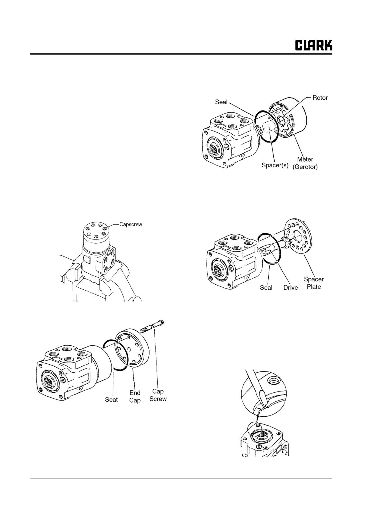
Group 25, Steering Column and Gear
5. Remove meter (gerotor). Be careful not to drop star
Disassembly
(rotor).
Cleanliness is extremely important when repairing a steer-
ing gear. Work in a clean area. Before disconnecting lines,
clean port area of unit thoroughly. Use a wire brush to
remove foreign material and debris from around exterior
joints of the unit.
NOTE
Although not all illustrations show the unit in
a vise, it is recommended to keep the unit in
the vise during disassembly. Follow the
clamping procedures explained throughout
the text.
6. Remove seal from meter.
Meter (Gerotor) End
7. Remove drive spacer(s).
1. Clamp unit in vise, meter end up. Clamp lightly on
8. Remove drive.
edges of mounting area, as shown. Use protective
material on vise jaws. Do not overtighten jaws.
9. Remove spacer plate.
2. Remove capscrews.
10.
10.Remove seal from housing.
Control End
11. Remove housing from vise and place on a clean soft
cloth to protect surface finish. Use a thin-bladed
screwdriver to pry retaining ring from housing.
3. Remove end cap.
4. Remove seal from end cap.
25-5-2 • Steering Gear Overhaul
SM 765, Dec ’06
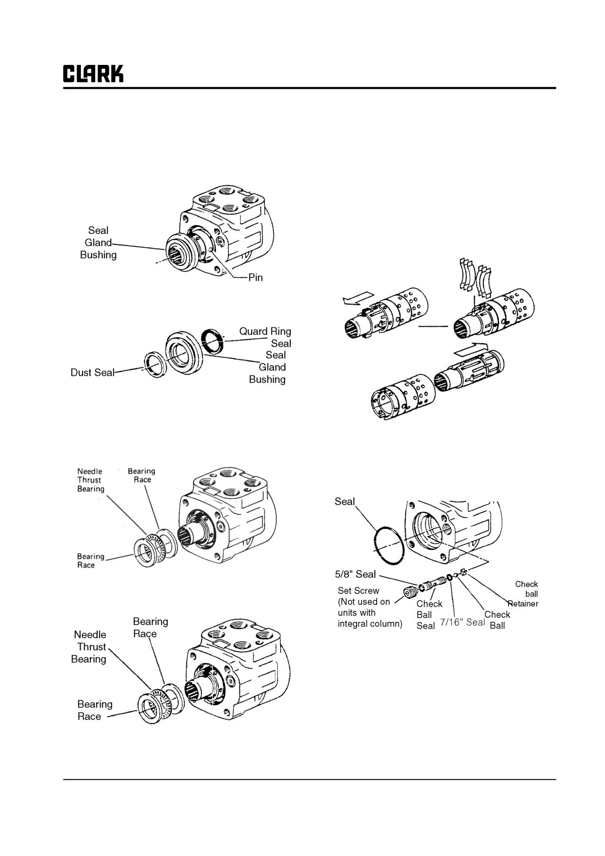
Group 25, Steering Column and Gear
12. Place assembly so shaft is horizontal. Rotate spool
IMPORTANT
and sleeve until pin is horizontal. Push spool and
Do not bind spool and sleeve in housing.
sleeve assembly forward with your thumbs just far
Rotate spool and sleeve assembly slowly
enough to free seal gland bushing from housing.
when removing from housing.
Remove bushing.
17. Push pin from spool and sleeve assembly.
18. Push spool partially from control end of sleeve, then
remove six centering springs from spool carefully by
hand. Note their position in the unit before they are
removed.
13. Remove quad ring seal from seal gland bushing.
14. Use a thin-bladed screwdriver to pry dust seal from
seal gland bushing. Do not damage bushing.
15. Remove two bearing races and the needle thrust bear-
19. Push spool back through and out of sleeve. Rotate
ing from spool and sleeve assembly.
spool slowly when removing from sleeve.
20. Remove seal from housing.
16. Remove spool and sleeve assembly from cap (14-
hole) end of housing.
21. Remove set screw from housing.
22. Screw a 1/8-inch-24 NC machine screw into end of
check ball seat. Then pull on screw with pliers to lift
seat out of housing.
23. Remove two seals from check valve seat.
24. Tip housing to remove check ball and check ball
retainer.
SM 765, Dec ’06
Steering Gear Overhaul • 25-5-3
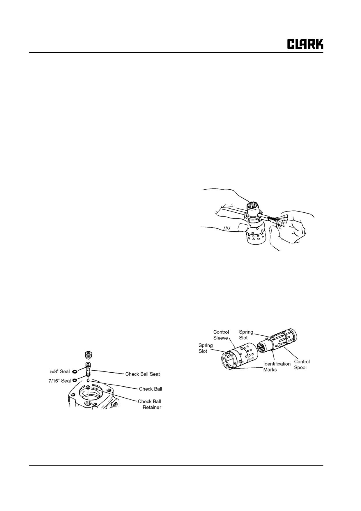
Group 25, Steering Column and Gear
4.
Lubricate check ball seat and seals thoroughly before
Parts Inspection
installing seat in housing. When installing seat do not
Inspect all parts for damage, cracks, broken parts, dam-
twist or damage seals. Install check ball seat in hous-
aged threads, corrosion or erosion of surfaces, worn spots,
ing; insert open end of seat first. Push check ball seat
nicks or scratches.
to bottom of hole.
Check all mating surfaces. Replace any parts that have
5.
Install set screw. Use a 5/16-inch Allen wrench to
scratches or burrs that could cause leakage. Discard all old
torque set screw to 11 N⋅m (100 in-lb; 8.3 ft⋅lb). To
seals and replace with new ones.
prevent interference of parts, make sure top of set
screw is slightly below housing mounting surface.
Clean all metal parts in clean solvent. Blow dry with air.
Do not wipe dry with cloth or paper towel because lint or
6.
Assemble spool and sleeve carefully so that the
other matter can get into the hydraulic system and cause
spring slots line up at the same end. Rotate spool
damage. Do not use a coarse grit or try to file or grind
while sliding parts together. Some spool and sleeve
these parts.
sets have identification marks ; align these marks.
Test for free rotation. Spool should rotate smoothly
If parts are left exposed, cover them with a clean cover to
in sleeve with finger tip force applied at splined end.
prevent airborne dust from collecting on them.
Reassembly
Refer to Service Parts Book when ordering replacement
parts. A good service policy is to replace all old seals with
new seals at overhaul.
NOTE
Lubricate all seals (with exception of new
quad ring seal) with clean petroleum jelly
7.
Bring spring slots of both parts in line and stand parts
such as Vaseline.
on end of bench. Insert spring installation tool (avail-
Do not use excessive lubricant on seals for
able as Part No. 6000057) through spring slots of
meter (gerotor) section.
both parts. Position three pairs of centering springs
Make sure all parts are clean and free of
(or two sets of 3 each) on bench so that extended
dust. Before assembly, lightly coat all internal
edge is down and arched center section is together. In
metal parts with oil.
this position, insert one end of entire spring set into
spring installation tool, as shown.
Control End
1. Use a needle-nosed pliers to lower check ball retainer
into check valve hole of housing. Make sure retainer
is straight (not tilted on edge) in housing.
On those units which use the low torque centering
springs, there are two pairs of centering springs (or
two sets of each) and one pair (two) spring spacers.
The spring spacers are installed together between the
two sets of centering springs. The installation proce-
dure is the same as that used on the standard (three
2. Install check ball in housing.
pairs of centering springs) units.
3. Lubricate 5/8-inch diameter seal and 7/16-inch diam-
eter seal. Install seals on check ball seat, as above.
25-5-4 • Steering Gear Overhaul
SM 765, Dec ’06
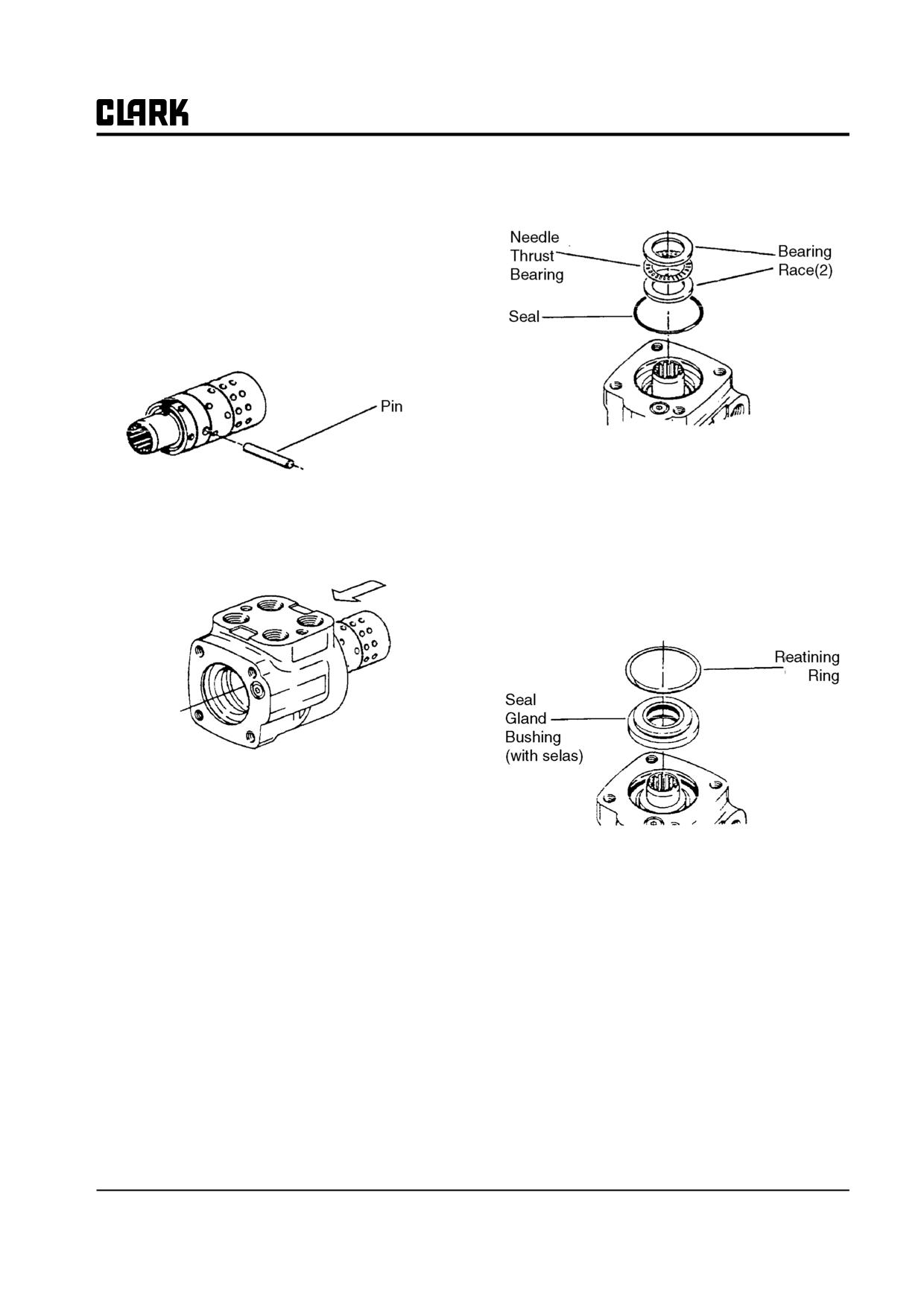
Group 25, Steering Column and Gear
8. Compress extended end of centering spring set and
13. Install two bearing races and the needle thrust bear-
push into spool sleeve assembly withdrawing instal-
ing in the order shown.
lation tool at the same time.
9. Center the spring set in the parts so that they push
down evenly and flush with the upper surface of the
spool and sleeve.
10. Install pin through spool and sleeve assembly until
pin becomes flush at both sides of sleeve.
14. Install 1-1/4-inch diameter dust seal in seal gland
bushing; flat or smooth side of dust seal must face
down towards bushing.
11. Position the spool and sleeve assembly so that the
splined end of the spool enters the 14-hole end of
15. Install dry quad ring seal in seal gland bushing.
housing first.
Smooth seal in place with your finger. Do not use any
seal that falls freely into pocket of bushing. Seal
should not “fall” into place but should require light
force to seat.
IMPORTANT
Be extremely careful that the parts do not tilt
out of position while being installed. Push
parts gently into place with slight rotating
action; keep pin nearly horizontal. Push the
spool assembly entirely within the housing
bore until the parts are flush at the meter end
or 14-hole end of housing. Do not push the
spool assembly beyond this point to prevent
the cross pin from dropping into the dis-
charge groove of the housing. With the spool
assembly in this flush position, check for free
rotation within the housing by turning with
light finger tip force at the splined end.
12. Place housing on clean, lint free cloth. Install 2-1/8-
inch diameter seal in housing.
SM 765, Dec ’06
Steering Gear Overhaul • 25-5-5
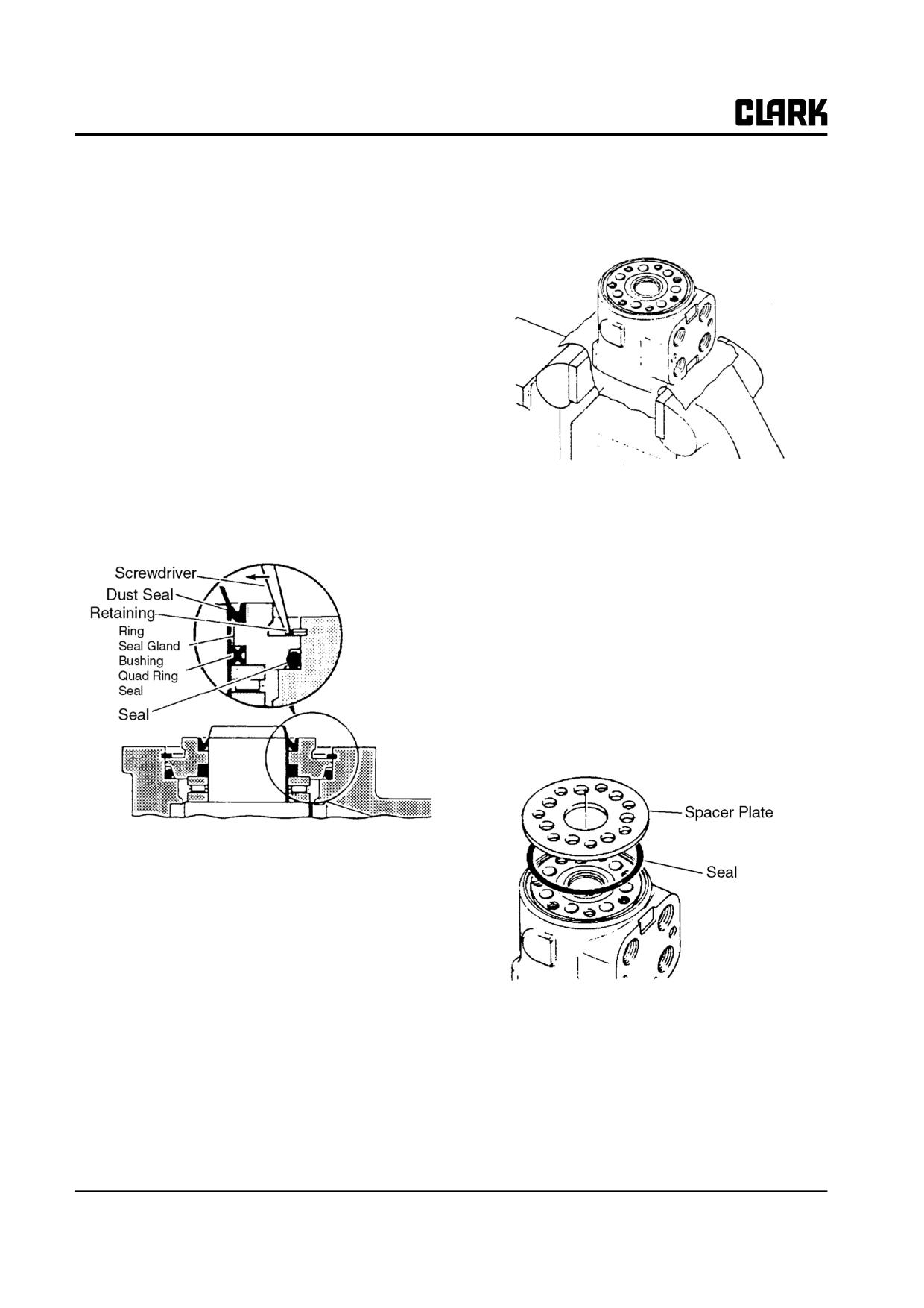
Group 25, Steering Column and Gear
16. Install seal gland bushing over the spool end with a
Meter (Gerotor) End
twisting motion. Tap the bushing in place with a rub-
ber hammer. Make sure the bushing is flush against
18. Clamp housing in vise, as shown. Clamp lightly on
the bearing race.
edges of mounting area. Do not overtighten jaws.
On those units which use the Teflon seal, install the
Teflon back-up ring into the recess cut into the seal
gland bushing. Install the Teflon seal over the spool
end, then carefully install the seal gland bushing over
the spool end using a rotary motion.
NOTE
The seal gland bushing which is used with the
Teflon seal is not the same as the seal gland
bushing used with the standard quad-ring
seal. The seal gland bushing with the Teflon
seal has an identification groove cut into the
outer diameter of the bushing. The grooved
bushings can only be used with the Teflon
NOTICE
seals and the non-grooved bushings used only
Check to ensure that the spool and sleeve are
with the quad-ring seals.
flush or slightly below the surface of the
housing.
IMPORTANT
Clean the upper surface of the housing by
wiping with the palm of clean hand. Clean
each of the flat surfaces of the meter section
parts in a similar way when ready for reas-
sembly. Do not use cloth or paper to clean
surfaces.
19. Install 3-inch diameter seal in housing.
17. Install retaining ring in housing. After installing ring,
tap on ring or pry with screwdriver around entire cir-
cumference of ring to properly seat ring in groove.
20. Install spacer plate. Align bolt holes in spacer plate
with tapped holes in housing.
25-5-6 • Steering Gear Overhaul
SM 765, Dec ’06
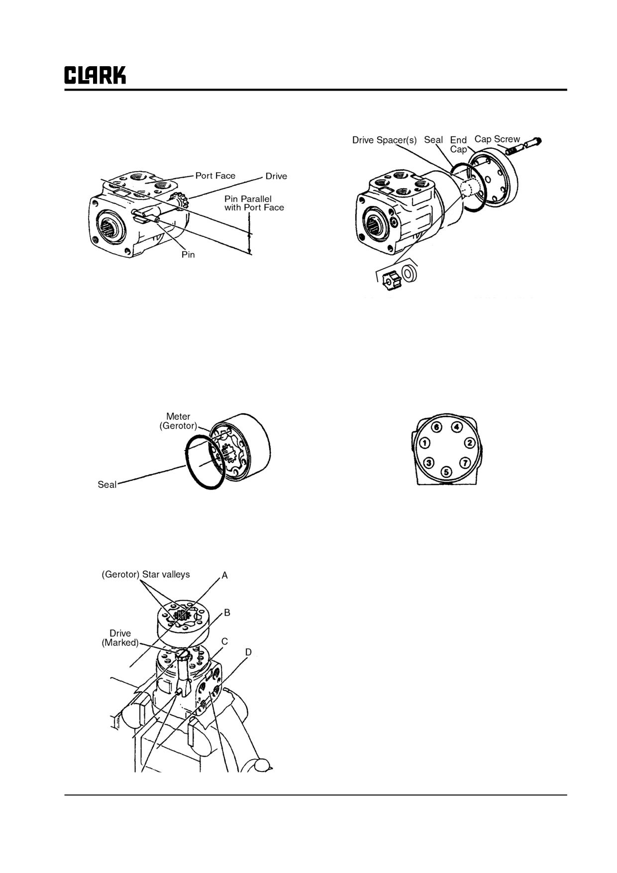
Group 25, Steering Column and Gear
21. Rotate spool and sleeve assembly until pin is parallel
24. Install drive spacer(s) when used, in meter.
with port face. Install drive, making sure you engage
drive with pin.
IMPORTANT
Failure to properly install drive and pin may
cause unit to self steer.
25. Install 3-inch diameter seal in end cap.
26. Install end cap on gerotor, and align holes.
NOTE
27. Install 7 dry cap screws in end cap. Pretighten screws
To assure proper alignment, mark spline end
to initial torque of 17 N⋅m (150 in⋅lb), then torque
of drive shaft with a line parallel to slot on
screws to final torque of 31 N⋅m (275 in⋅lb) in the
other end, before installing.
sequence shown.
22. Install 3-inch diameter seal in meter (gerotor).
23. With seal side of meter toward spacer plate, align star
valleys on drive. Note the parallel relationship of ref-
28. Inspect the assembly to be sure all parts have been
erence lines A, B, C, and D in figure. Align bolt
installed and fasteners correctly installed and tight-
holes without disengaging meter from drive. Be sure
ened.
star has engaged drive spline in position shown.
SM 765, Dec ’06
Steering Gear Overhaul • 25-5-7
NOTE :
Group 25, Steering Column and Gear
SM 765, Dec ’06
GROUP 26
GROUP 26
STEERING AXLE
Steering Axle Specifications and Description
Section 1
Steering Wheel Bearing
Maintenance and Adjustment
Section 2
Steering Axle Removal and Installation
Section 3
Steering Axle Overhaul
Section 4
Steering Cylinder Removal and Installation
Section 5
Steering Cylinder Overhaul
Section 6
Pivot-Turn Steering Axle Maintenance
Section 7
SM 765, Dec ’06
Group 26, Steering Axle
NOTE :
Group 26, Steering Axle
SM 765, Dec ’06
Group 26, Steer Axle
Section 1
Steering Axle Specifications and Description
Specifications
Service Intervals
Steering System Relief Pressure Setting : 10000 kPa
Steering Linkage Inspection and Lubrication: Every 50-
(1450 psi)
250 hours and each PM.
Steer Cylinder Type : Double-acting, piston-type
Steer Wheel Bearing Inspection and Lubrication: Every
50-250 hours of operation.
Turning Arc : 83° maximum inside turning angle
59° maximum outside turning angle.
Steer Cylinder Seals Leakage Check: Every 50-250 hours
and each PM.
Bearing Grease : Grade No. 2 EP multi-purpose grease,
Clark Part MS-107C.
Steer Axle Mounting Inspection: Every 50-250 hours and
each PM.
Fastener Torques
Power Steering Relief Pressure Check: Every year or 2000
hours of operation.
Steer Axle Mounting Bolts: 170-190 N⋅m (125-140 ft-lb)
Cylinder to Axle Mounting Bolts: 280-320 N⋅m (205-
Description
234.5 ft-lb)
The steer axle has the steer cylinder, steer knuckles, and
Steering Link to Steering Knuckle Nuts: 135-150 N⋅m
steering links mounted on it. All these components can be
(98-110 ft-lb)
removed, serviced, and replaced.
Steer Knuckle King Pin Castle Nuts: See installation pro-
The steering gear (steering control unit) at the base of the
cedures in Section 4, “Steer Axle Overhaul.
steering column directs hydraulic fluid to one end or the
other of the steer cylinder to pivot the steer wheels.
The steer axle is bolted to the truck frame. The steer cylin-
der is connected to the steering knuckles by steer links.
Mounting trunnions allow the axle to tilt independently of
the truck and “silent” mounts cushion the axle on the trun-
nions.
All bearings used in the steer axle linkage have lubrication
fittings and are serviceable. Axle removal, replacement,
and service for all components, including overhaul of the
steer cylinder, is explained in the Sections for this Group.
SM 765, Dec ’06
Steering Axle Specifications and Description • 26-1-1
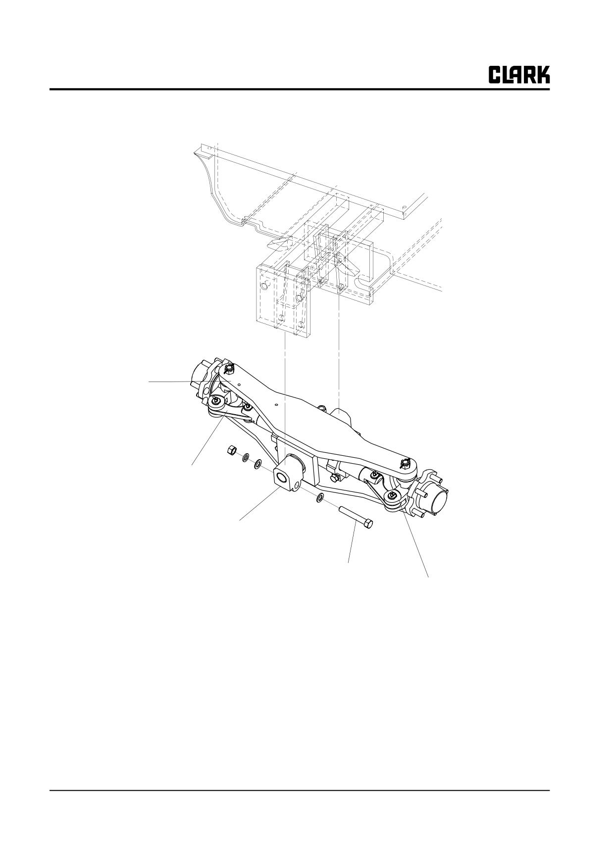
Group 26, Steer Axle
Steer Axle
Steering Link
Silent Mount
Torque:
335-409 N.m
Steering Knuckle
247-301 Ib.ft
Steer Axle and Mounting
26-1-2 • Steering Axle Specifications and Description
SM 765, Dec ’06
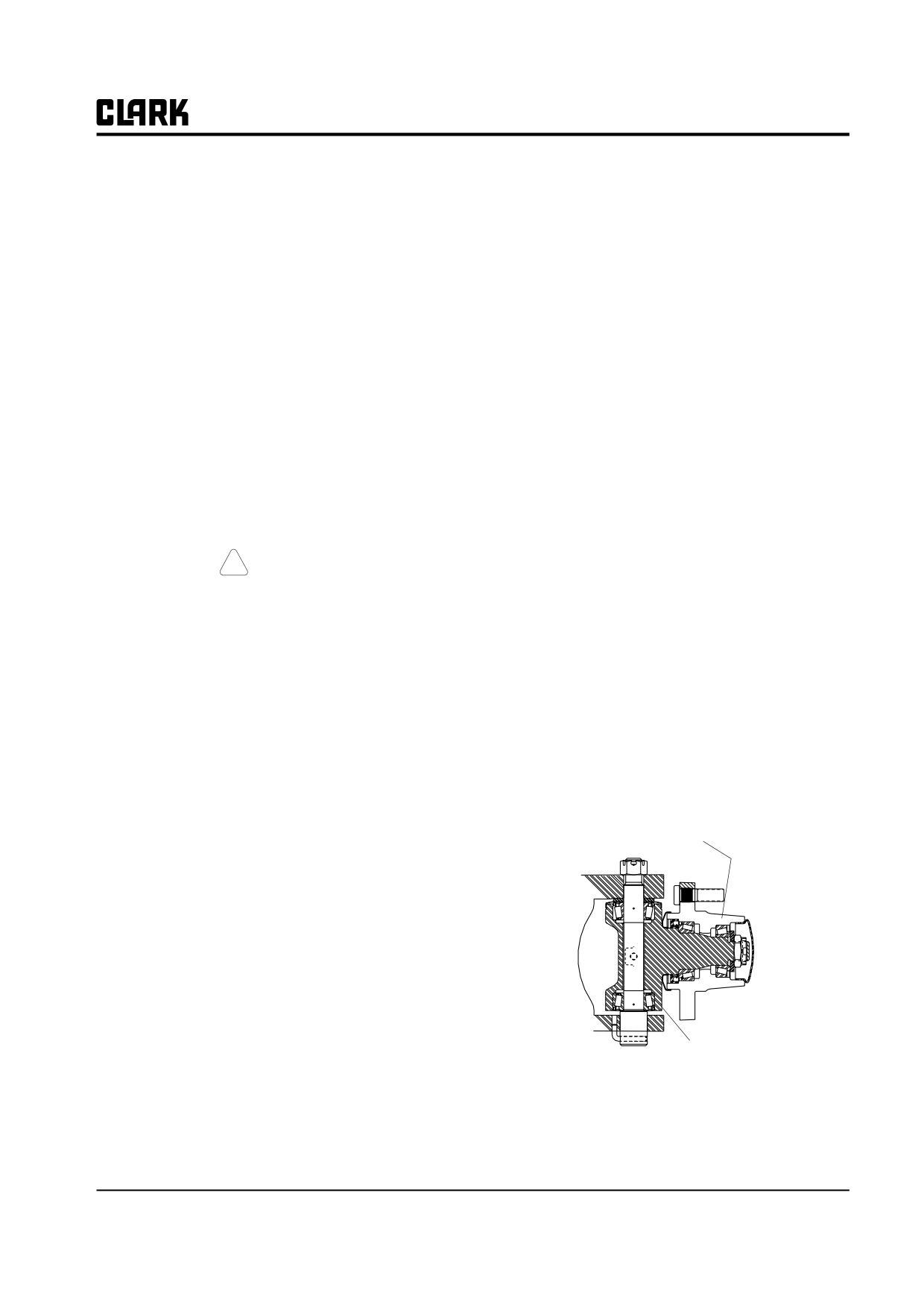
Group 26, Steer Axle
Section 2
Steering Axle Wheel Bearing maintenance and Adjustment
Wheel Bearing Check
1
Wheel Bearing Lubrication
1
Bearing Disassembly
2
Bearing Reassembly
3
Wheel Bearing Adjustment
4
IMPORTANT
Before removing any component for overhaul, make sure the correct repair parts, seals, and gasket sets
are available.
movement, the bearings require additional service and/or
! CAUTION
adjustment.
SAFE PARKING. Before working on truck:
1. Park truck on a hard, level, and solid
Wheel Bearing Lubrication
surface, such as a concrete floor with no
These procedures cover bearing lubrication for steer
gaps or breaks.
wheels used on the truck ; pneumatic-tire wheels which
2. Put upright in vertical position and fully
are mounted on a hub that contains the bearing compo-
lower the forks or attachment.
nents. Use the procedures to clean, repack and adjust bear-
3. Put all controls in neutral. Turn key
ings for both the pneumatic-tire hub.
switch OFF and remove key.
The bearing components and arrangement are the same
4. Apply the parking brake and block the
for both the pneumatic types. Instructions for repacking/
wheels.
lubricating the bearing components apply to both types.
5. Remove Battery Connector.
Pneumatic-Tire
Wheel Mounting
Wheel Bearing Check
Hub
Wheel bearings check should be performed every PM.
Wheel bearings need adjustment only after 2000 hours or
as needed. It is recommended that you clean and repack
the bearings before adjustment. Check hourmeter total
hours and refer to the truck’s PM schedule. See steer
wheel bearing lubrication procedure below.
To check the steer wheel bearings for excessive free play
or looseness:
1. Grasp the wheel with both hands and try to move it
by a rocking motion top-to-bottom.
Steer Axle Knuckle
2. Try to pull it in and out along the wheel spindle.
Watch for excessive free movement in wheel bearings or
wheel-assembly
steering knuckle bearings. There should be a small
amount of free movement. If the wheel has excessive free
SM 765, Dec ’06
Steering Axle Wheel Bearing maintenance and Adjustment • 26-2-1
Group 26, Steer Axle
Bearing Disassembly
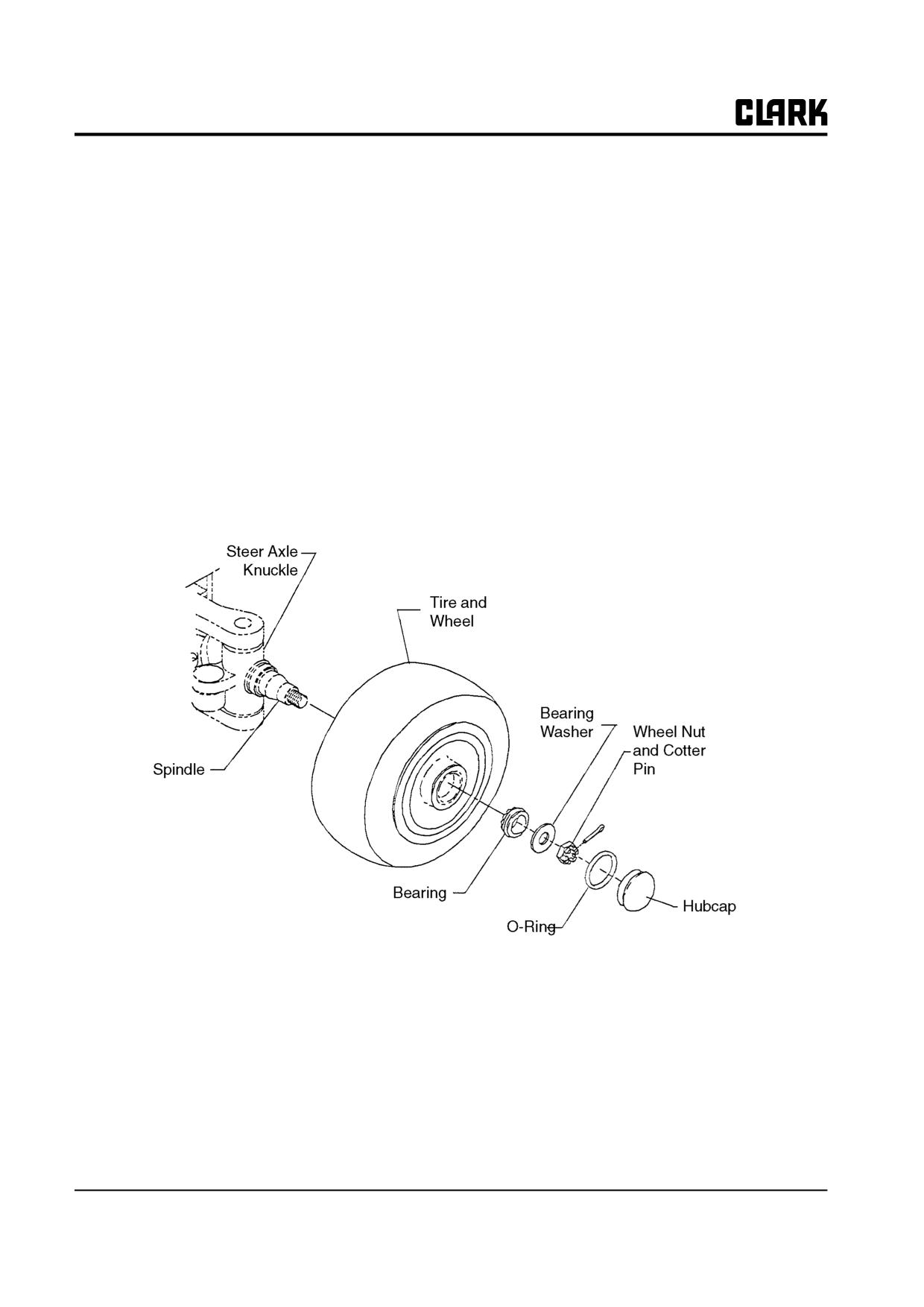
2. Refer to the exploded view illustration of the wheel
bearing assembly. Loosen and remove the hubcap
1. Be sure truck is parked and blocked up correctly and
from wheel or hub. You may have to lightly tap hub
safely to raise steer wheels off the floor. Refer to
cap with a hammer and chisel and use a pry bar to
“Lifting, Jacking, and Blocking,” in the Group “SA.”
loosen. Be careful not to damage mounting surfaces.
Remove O-ring from hubcap.
NOTE
Because of the heavy weight of the wheel and
3. Clean the excess grease from around the wheel nut.
tire, it is suggested to first remove the wheel
4. Remove cotter pin, loosen and remove wheel nut and
and tire assembly from spindle when servic-
bearing washer.
ing the bearings to avoid damage to the
grease seal when the wheel hub is moved off
or on the spindle. It also makes the work sim-
pler and easier.
Wheel Bearing Assembly.
26-2-2 • Steering Axle Wheel Bearing maintenance and Adjustment
SM 765, Dec ’06
Group 26, Steer Axle
5. Pull the wheel or hub off the spindle. Support the
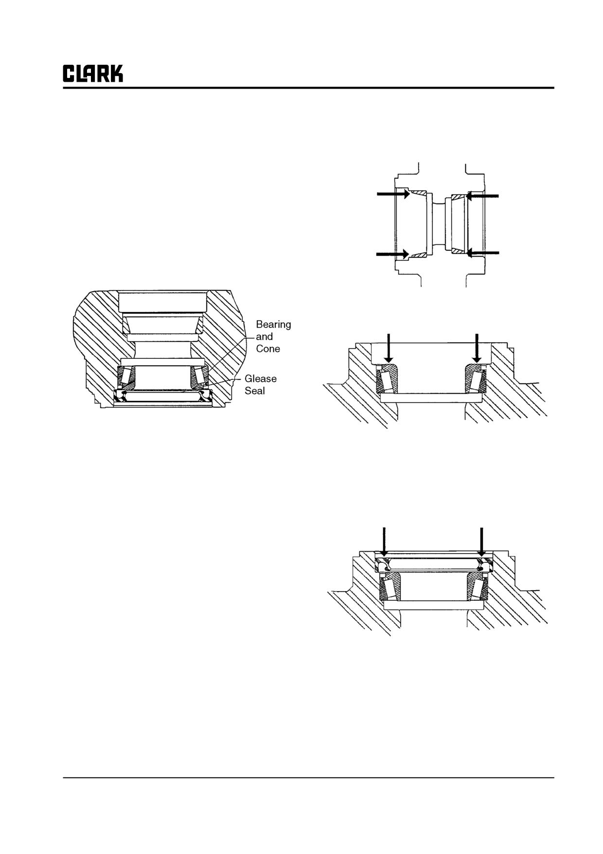
1. Install new inner and outer bearing cups by pressing
wheel or hub to avoid dragging the grease seal at the
into hub or wheel. Be sure cups are fully seated in
back side across the thread on spindle end.
bore.
6. Clean the old grease out of center of the wheel or
hub.
7. To remove inner bearing and seal, lay wheel or hub
down with outer edge up (support hub on blocking).
Remove the inner bearing cone and grease seal, using
a brass drift pin, rod, or piece of pipe to drive the
bearing and seal out of the hub.
2. Pack the bearings with grease and install the inner
bearing in the hub or wheel.
8. Clean and inspect the bearing cups and cones for
3. Pack cavity between bearing and grease seal half full
wear or other damage. Replace, as necessary.
with grease.
IMPORTANT
4. Install new grease seal in hub or wheel inner bore.
Keep serviceable bearing cups and cones
Apply coating of grease to inside diameter of seal
matched together. Always replace bearing
lips prior to assembly, then install seal in hub or
cups and cones as a set.
wheel bore.
9. Inspect grease seal for wear and damage. Replace as
necessary. It is recommended to install a new grease
seal whenever old ones are removed.
10. Use a standard puller to remove bearing cups from
hub or wheel if bearings require replacement.
Bearing Reassembly
NOTE
5. Carefully press or tap grease seal into place with
Use Grade No. 2 EP multi-purpose grease,
asoftfaced mallet until seal is seated in bottom of
Clark MS-107C.
bore.
6. Install hub or wheel on spindle. Be careful not to
damage grease seal lip when moving the hub over the
end of spindle and threads.
7. Pack cavity in hub between bearings one-half full
with grease.
SM 765, Dec ’06
Steering Axle Wheel Bearing maintenance and Adjustment • 26-2-3
Group 26, Steer Axle
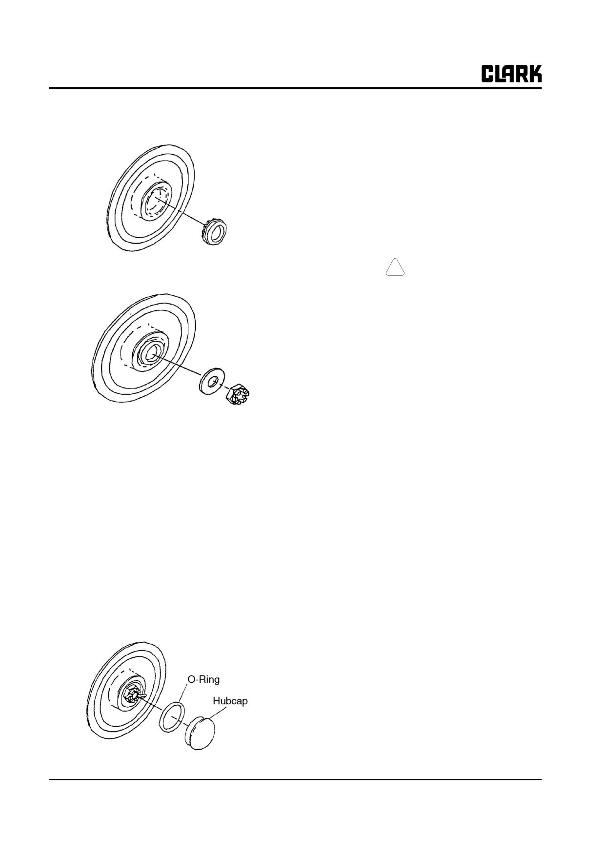
8.
Install the outer wheel bearing after it has been
Wheel Bearing Adjustment
packed with grease.
The steer wheel bearings are retained and adjusted by the
wheel nut.
NOTE
You should clean and repack the wheel bear-
ings before performing a wheel bearing
adjustment. See “Wheel Bearing Lubrica-
tion” in this Section for the complete proce-
dure.
9.
Install bearing washer and hand tighten wheel nut.
!
CAUTION
SAFE PARKING. REFER TO PAGE 1.
1.
Make sure the truck is parked on a level, hard sur-
face, the upright is fully lowered, the drive wheels
are chocked, and the steer wheels are jacked and
blocked securely. Refer to “Lifting, Jacking, and
Blocking” for safe procedures.
2.
Remove hubcap.
3.
Remove and discard cotter pin.
4.
Loosen wheel nut.
10.
Rotate hub or wheel counter clockwise and torque
wheel nut to 27-31 N⋅m (20-23 ft-lb).
5.
After wheel nut is loosened, hit the top of wheel to
loosen the bearings. This moves the bearings free of
11.
Back wheel nut up until it is loose.
their seated, running position.
12.
While turning the hub or wheel counter clockwise,
6.
Rotate hub or wheel counter clockwise and torque
torque the wheel nut to 2.3-2.8 N⋅m (1.7-2 ft-lb).
wheel nut to 27-31 N⋅m (20-23 ft-lb).
13.
Back up wheel nut to nearest slot and install new cot-
7.
Back wheel nut up until it is loose.
ter pin. Bend cotter pin tabs.
8.
While turning the hub or wheel counter clockwise,
14.
Recheck for correct bearing adjustment by rotating
torque the wheel nut to 2.3-2.8 N⋅m (1.7-2 ft-lb).
the wheel by hand. Wheel should rotate freely or
with only slight “drag”. Readjust bearings by adjust-
9.
Back up wheel nut to nearest castellation slot and
ing wheel nut as necessary to avoid binding in bear-
install new cotter pin.
ings.
10.
Recheck for correct bearing adjustment by rotating
15.
Pack the area around wheel nut with grease.
the wheel by hand. Wheel should rotate freely or
with only slight “drag”. Readjust bearings by adjust-
16.
Refit O-ring on hubcap and install hubcap by tapping
ing wheel nut as necessary to avoid binding in bear-
into place with a rubber or plastic-faced hammer.
ings.
11.
Bend cotter pin tabs over.
12.
Pack the area around wheel nut with grease.
13.
Refit O-ring on hubcap if removed or replaced and
install hubcap by tapping into place with a rubber or
plastic-faced hammer.
26-2-4 • Steering Axle Wheel Bearing maintenance and Adjustment
SM 765, Dec ’06
Group 26, Steer Axle
Section 3
Steering Axle Removal and Replacement
Steer Axle Removal
2
Steer Axle Replacement
3
SM 765, Dec ’06
Steering Axle Removal and Replacement • 26-3-1
Group 26, Steer Axle
! CAUTION
SAFE PARKING. Before working on truck:
1. Park truck on a hard, level, and solid
surface, such as a concrete floor with no
gaps or breaks.
2. Put upright in vertical position and fully
lower the forks or attachment.
3. Put all controls in neutral. Turn key
switch OFF and remove key.
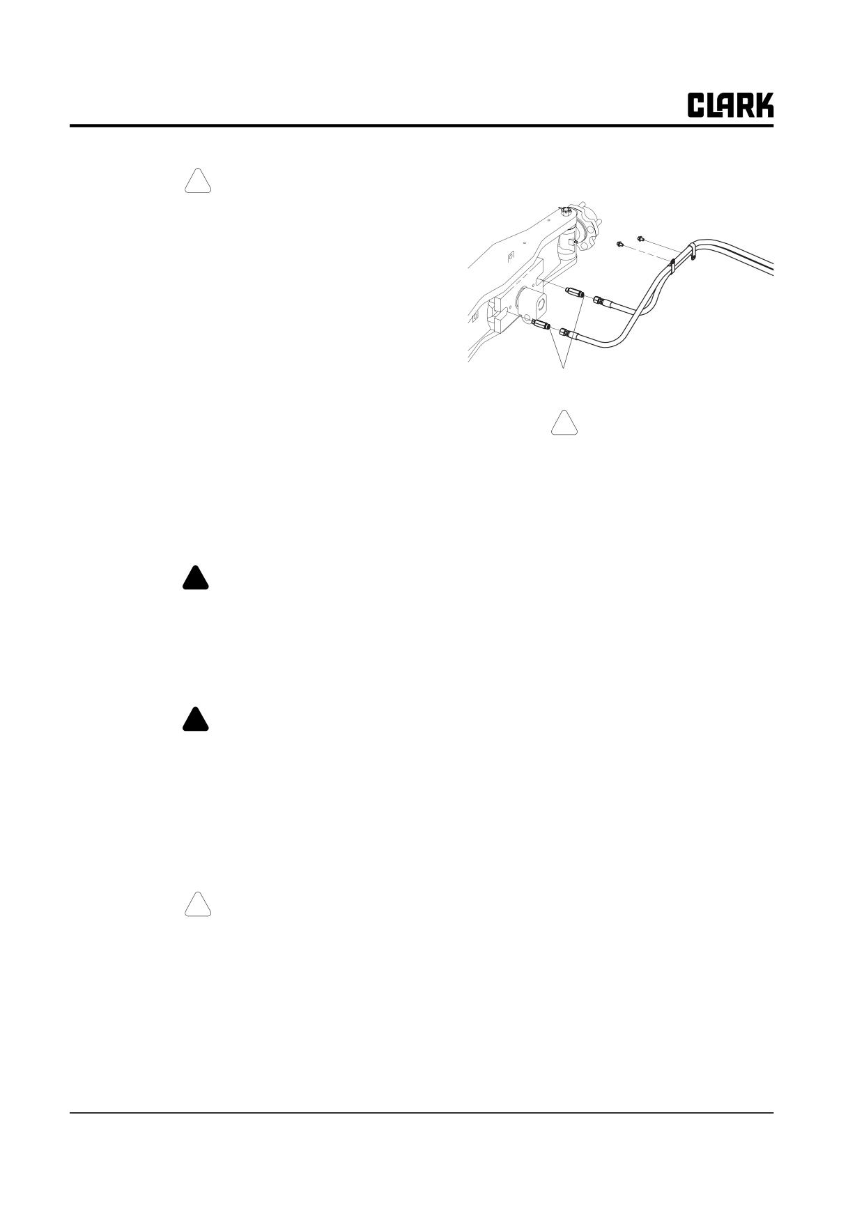
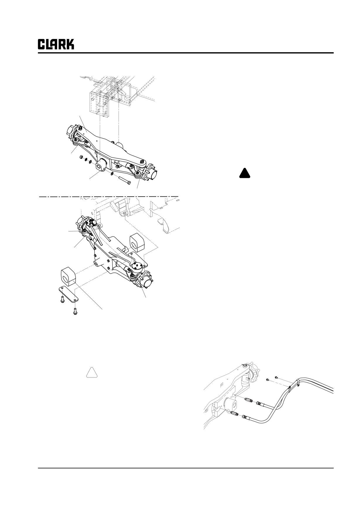
Disconnect cylinder lines here.
4. Apply the parking brake and block the
wheels.
!
CAUTION
Steer Axle Removal
Axle must be supported before any attaching
fasteners are removed.
1.
Remove the counterweight before removing the steer
axle. Refer to Group 38, Section 2, “Counterweight
4.
If another lift truck is used to temporarily support
Removal and Replacement.” (It is possible to remove
axle while removing, put forks in center of carriage
the steer axle without removing the counterweight
about 305 mm (12 in) apart. Move forks under axle
but much easier if it is removed).
and raise itjust toremoveits weight from mounting-
bolts. Or use a portable floor jack to carefully support
! WARNING
the axle at its center section.
Do not remove the counterweight unless you
5.
Loosen and remove nuts from axle mounting bolts,
have training and are familiar with the cor-
front and rear.
rect procedures. Counterweights can fall if
not handled correctly and cause severe injury
• Remove the mount plates from the bottom of the
or death.
trunnion mounts of the steer axle (Figure A.).
6.
Remove the mounting bolts.
! WARNING
7.
Lower the axle allowing its weight to pull the silent
blocks out of frame recesses. Watch the silent blocks
Do not raise truck by hoisting on overhead
to be sure they release freely from frame. You may
guard or by jacking or lifting on counter-
have to loosen blocks with a pry bar if they bind.
weight.
8.
Carefully withdraw the axle from beneath the truck
2.
Block the drive wheels of the truck and raise and
and move to safe storage.
block the rear end. Remove steer wheels. See “Lift-
ing, Jacking, and Blocking” in Group “SA” for safe
procedures to jack the truck.
! CAUTION
Make sure truck is correctly raised and
safely blocked using hardwood blocks under
the frame. Be sure the blocking will permit
installation of the axle without disturbing the
blocking.
3.
loosen and remove hydraulic steering lines from
steering cylinder. Plug fittings and cap open ends of
lines. Keep all hydraulic fittings and openings clean.
26-3-2 • Steering Axle Removal and Replacement
SM 765, Dec ’06
Group 26, Steer Axle
2.
Make sure that the silent blocks are positioned cor-
rectly front and rear on the steer axle trunnions at the
Old Steer Axle
start of installation. Align the silent blocks square
with the axle.
3.
Use a fork lift truck or mobile floor jack to tempo-
Steer Axle
rarily support and raise the axle into place under the
truck. If another lift truck is used to handle axle, cen-
ter the forks with about 305 mm (12 in) spread
between them. Place steer axle assembly in secure
position on fork tips.
If hydraulic jack is used, be sure axle is securely sup-
Steering Link
ported on jack pad.
!
WARNING
Silent Mount
Heavy components can fall and cause severe
Steering Knuckle
injury. Keep your body clear at all times.
New Steer Axle
4.
Install axle assembly into frame by slowly raising it
up while guiding silent block bushings into frame
sockets.
Steer Axle
5.
Install silent block mounting bolts through frame
socket holes and silent block, front and rear.
Reset the two mounting plates under the silent blocks
Steering Link
of the axle.
6.
Install silent mount fasteners and tighten to 240-265
N⋅m (180-196 ft-lb).
7.
Remove temporary axle support from under truck.
8.
Connect the hydraulic lines to steering cylinder.
Steering Knuckle
Tighten fittings to 12-14 N⋅m (106-123 in-lb; 8.8-
10.3 ft-lb).
Silent Mount
IMPORTANT
Steer Axle Mounting
Make sure all fittings and openings on the
Steer Axle Replacement
hydraulic lines are clean.
Replacement is the reverse of removal. Refer to Figure A
for replacement.
! CAUTION
Make sure truck is correctly raised and
safely blocked using hardwood blocks under
the frame. Be sure the blocking will permit
installation of the axle without disturbing the
blocking.
1. If silent blocks have been removed from axle, install
new silent block assemblies. Use a rubber or plastic
mallet to seat the silent mounts onto the axle trun-
nions.
SM 765, Dec ’06
Steering Axle Removal and Replacement • 26-3-3
Group 26, Steer Axle
9. Carefully raise the truck off the blocking as described
in “Lifting, Jacking and Blocking”. Remove the
blocking and lower the truck to the floor.
10. If removed, reinstall countenveight; refer to Group
38, Section
2, “Counterweight Removal and
Replacement”.
11. Check the axle and steering system for proper opera-
tion. Operate the steering gear to move the steer
wheels to maximum travel in both directions. Note
any unusual motion or noise.
If the system appears to be operating correctly, drive
the truck slowly. Fully steer the vehicle in each direc-
tion and check response.
12. Check steering cylinder hose line connections and
cylinder rod seals for any evidence of oil leakage
before returning the truck to service.
26-3-4 • Steering Axle Removal and Replacement
SM 765, Dec ’06
Group 26, Steer Axle
Section 4
Steering Axle Overhaul
Preparation for Steer Axle Disassemble and Overhaul
2
Steer Axle Disassembly
2
Parts Inspection
3
Steer Axle Reassembly
3
IMPORTANT
Before removing any component for overhaul, make sure the correct repair parts, seals, and gasket sets
are available.
! CAUTION
SAFE PARKING. Before working on truck:
1. Park truck on a hard, level, and solid surface, such as a concrete floor with no gaps
or breaks.
2. Put upright in vertical position and fully lower the forks or attachment.
3. Put all controls in neutral. Turn key switch OFF and remove key.
4. Apply the parking brake and block the wheels.
SM 765, Dec ’06
Steering Axle Overhaul • 26-4-1
Group 26, Steer Axle
2.
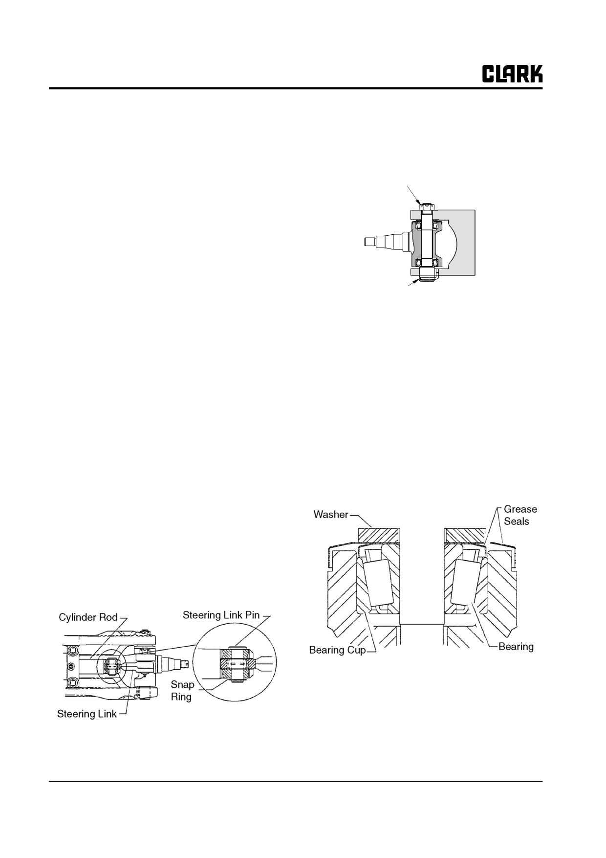
Remove and discard cotter pin from kingpin castel-
Preparation For Steer Axle
lated nut. Remove the nut.
Disassembly and Over haul
NOTE
Cleanliness is of extreme importance in the
Kingpin castel-
lated Nut
repair and overhaul of this assembly.
• Before starting disassembly, thoroughly clean the
axle assembly of all accumulations of dirt, oil, cor-
rosion, and other substances to prevent contamina-
tion of the parts during disassembly and overhaul.
• Work in a clean area.
• Keep all parts in order as disassembly progresses.
Kingpin
Take care to properly identify each part and its
Retainer Pin
order of removal. If necessary, keep notes and put
markings on parts using a non-destructive marker
such as a grease pencil or felt-tipped pen.
3.
Drive the kingpin down and out of the assembly.
• If necessary, see Section 3, “Steer Axle Removal
Remove the steering knuckle. Note right and left
and Replacement,” for the procedures to remove
knuckle parts.
the steer axle from the truck.
IMPORTANT
• See Section
5, “Steer Cylinder Removal and
Do not let the knuckle or pin fall when the
Replacement,” for the procedures to remove the
pin is removed.
steering cylinder and steering links from the steer
axle.
4.
Remove the kingpin retainer pin from the base of
• See Section 6, “Steering Cylinder Overhaul,” to
the kingpin.
disassemble the steer cylinder.
5.
Remove the knuckle bearing washers, dust covers,
upper and lower grease seals, bearings, and bear-
Steer Axle Disassembly
ing cups from the assembly.
To disassemble the steering knuckle, kingpin, and bearing
from the steer axle, it is not necessary to remove the axle
from the truck.
1. Remove the snap ring from the bottom of the steering
link pin and remove the pin. Steering link is free to
be removed from the cylinder rod and knuckle.
Bearing cups may be removed by hand, by using a bearing
puller, or by tapping out using a brass drift pin.
26-4-2 • Steering Axle Overhaul
SM 765, Dec ’06
Group 26, Steer Axle
3. Set the retainer pin into the king pin and slide the
Parts Inspection
king pin into the steer axle/knuckle bore.
1. Clean all bearings, cups, seals, pins, and other parts
IMPORTANT
in an approved cleaning fluid.
Make sure that retainer pin enters the hole in
2. Inspect all parts for scratches, chips and wear. Check
the underside of the axle
the steering arms of the knuckles to be sure they are
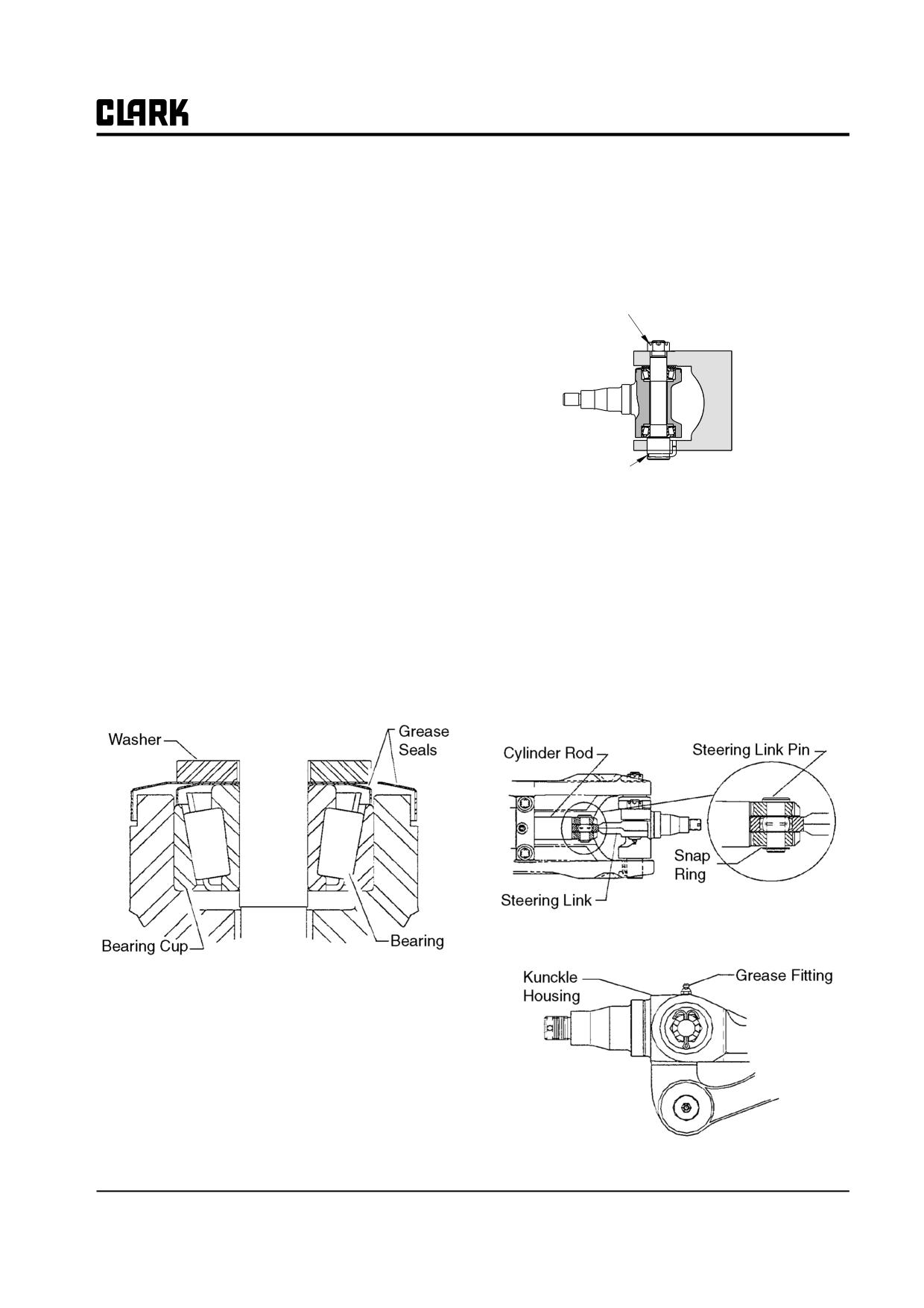
Kingpin castel-
not bent or twisted. Check all threaded parts for dam-
lated Nut
age.
3. Replace all parts which show damage.
4. If parts are to be left exposed, coat all mating sur-
faces of parts with a light coating of engine oil.
Steer Axle Reassembly
Kingpin
Recommended greasing procedure:
Retainer Pin
a. Use Grade No. 2 EP multi-purpose grease, Clark
4. Reset the kingpin castellated nut to the top of the
MS-107 or equivalent.
kingpin. Torque nut to 50-60 N⋅m (36.5-44 ft-lb).
b. Pack all tapered roller bearings with grease
before assembly.
5. Rotate the steer knuckle three times through its full
range of movement. Check to be sure that it is free to
c. Pack knuckle pin (bearing) seals with grease
rotate in the bearings without binding.
before assembly.
d. Fill steer link sockets with grease through grease
6. Loosen the kingpin nut and retorque the nut to 30-
35N⋅m (22.2-25.5 ft-lb).
fittings after axle is assembled.
7. Advance the nut to the next castellated slot and
1. Install the upper and lower knuckle bearing cups into
lock the nut into position with a new cotterpin.
the knuckle housing bore. Tap into place with a brass
Bendcotterpin tabs over.
drift pin or equivalent.
8. Replace steering link pin and snap ring to join the
cylinder rod to the steering link and knuckle.
9. Reinstall grease fitting in knuckle housing and lubri-
cate with recommended grease.
IMPORTANT
Make sure that bearing cup is fully seated
against the shoulder in bore. There must be
no gap left between cup and the shoulder in
the bore at assembly.
2. Apply grease to upper and lower knuckle bearings
and install bearings, grease seals, and washers to
bores of knuckle.
SM 765, Dec ’06
Steering Axle Overhaul • 26-4-3
NOTE :
Group 26, Steer Axle
SM 765, Dec ’06
Group 26, Steer Axle
Section 5
Steering Cylinder Removal and Replacement
! CAUTION
SAFE PARKING. Before working on truck:
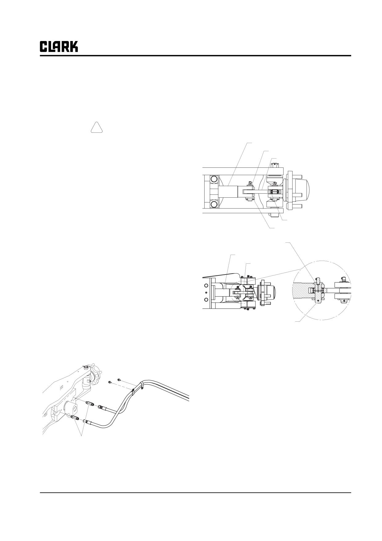
Steer Cylinder Rod
1. Park truck on a hard, level, and solid
Steering Link Pin
Steering Link
2. surface, such as a concrete floor with no
gaps or breaks.
3. Put upright in vertical position and fully
lower the forks or attachment.
4. Put all controls in neutral. Turn key
switch OFF and remove key.
5. Apply the parking brake and block the
wheels.
Old Steer Axle
Steering Link Bearing
Snap Ring
Steer Cylinder Removal
Steering Link Pin
The steer cylinder can be removed from the steer axle for
overhaul or replacement without removing the steer axle
Cylinder Rod
from the truck. The cylinder should be overhauled or
Steering Link
replaced if steering problems or troubleshooting informa-
tion indicate the cylinder is malfunctioning. See Group
2.5, Section 2, “Steering System Troubleshooting,” for
steering problem diagnoses. See Section 6 in this Group
for steer cylinder overhaul procedures.
1. Place a dram pan under the steer cylinder and remove
New Steer Axle
the hydraulic lines from the cylinder fittings. Cap fit-
Cotter Pin
tings and lines to prevent fluid from leaking and to
protect the components and hydraulic system from
NOTE
dust and dirt. Label hoses and fittings for correct
Mark left-side and right-side parts for cor-
reassembly.
rect reassembly.
3. Tap steer link pin upward until it clears the steering
link bearing and remove the pin.
4. Remove steer link bearing from steering link-to-cyl-
inder rod end bore.
5. Rotate the steering link away from the cylinder rod
end.
6. Repeat steps 1 through 5 for the opposite side of the
steer cylinder.
7. Remove the four steer cylinder mounting bolts and
Remove fittings.
washers from the steer axle. Removal torque on these
bolts can be as high as 405 N⋅m (300 ft-lb).
2. Remove the snap ring from the bottom of the steering
link pin. Steering link pin attaches steer cylinder rod
end to steering link.
SM 765, Dec ’06
Steering Cylinder Removal and Replacement • 26-5-1
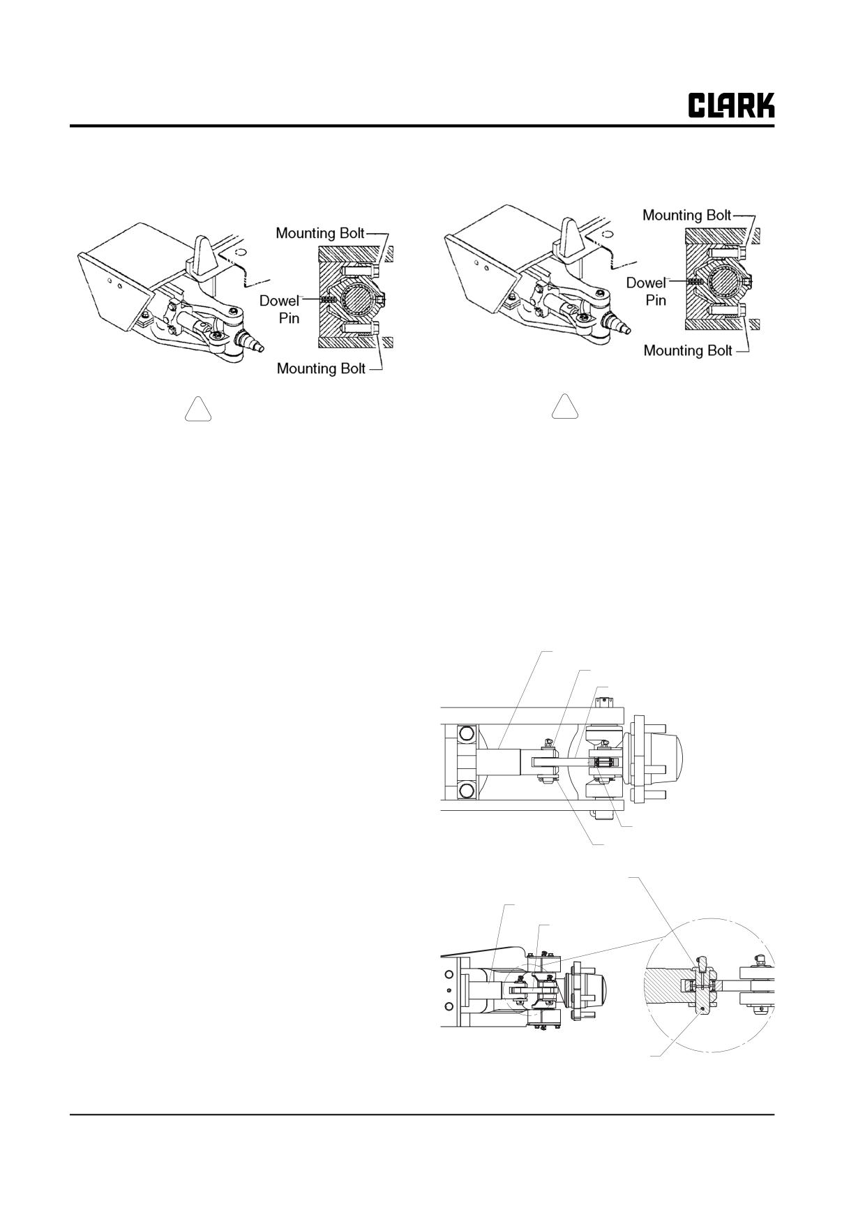
Group 26, Steer Axle
Cylinder is now ready to be removed from the steer axle
body. Cylinder must be lifted off dowel pins positioning
cylinder to axle body.
!
CAUTION
! CAUTION
Cylinder is somewhat heavy and bulky.
Cylinder is somewhat heavy and bulky.
When removing cylinder from mounting be
When remounting cylinder to steer axle
prepared to lift and move the full weight of
body, be prepared to lift and maneuver the
the cylinder.
full weight of the cylinder as you set it into
position.
Parts Inspection
2. Position the steering link with the cylinder rod end.
Reuse steer link bearing if still serviceable. Install
Completely inspect all parts:
new bearings if scoring or wear marks are evident or
1. Clean all bearings, cups, seals, pins, and other parts
if the bearings do not operate smoothly.
in an approved cleaning fluid.
2. Inspect all parts for scratches, chips, scoring, and
uneven or heavy wear. Check steering links to be sure
Steer Cylinder Rod
they are not bent or twisted. Check all threaded parts
Steering Link Pin
for damage.
Steering Link
3. Replace all parts showing excessive wear or signs of
damage.
4. If parts are to be left exposed, coat all mating sur-
faces of parts with a light layer of engine oil. Keep all
parts clean and covered.
5. Remove and clean all grease fittings before reassem-
Old Steer Axle
Steering Link Bearing
bling cylinder components.
Snap Ring
Refer to Section 6, “Steer Cylinder Overhaul”, if pressure
check or troubleshooting tips indicate a problem with
Steering Link Pin
steer cylinder performance.
Cylinder Rod
Steering Link
Steer Cylinder Replacement
1. Remount the steer cylinder onto the steer axle dowel
pins; set bolts and washers in place and torque
mounting bolts to 280-320 N⋅m (205-234.5 ft-lb).
New Steer Axle
Cotter Pin
26-5-2 • Steering Cylinder Removal and Replacement
SM 765, Dec ’06
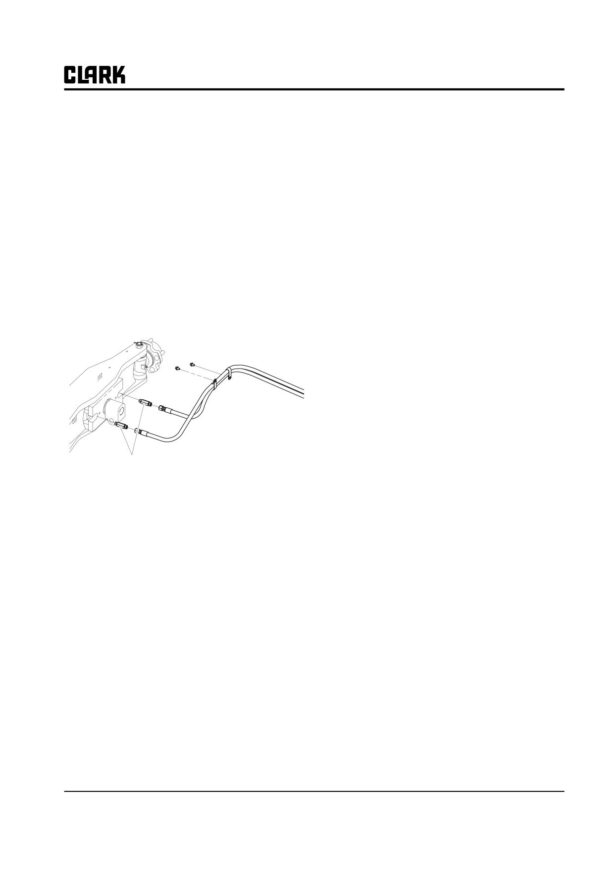
Group 26, Steer Axle
3. Rotate steering link into cylinder rod end and align
bearing hole with rod end.
4. Tap pin through steer link bearing hole with snap
ring groove on lower end.
IMPORTANT
Make sure bearing is properly aligned with
pin in the hole.
5. Install the snap ring to the steering link pin.
6. Repeat steps 1 to 5 for rod end-to-steering link con-
nection for opposite side.
7. Clean and replace hydraulic hoses on correct, clean,
cylinder fittings. See Group 40, Hydraulic Fitting
Tightening Procedure” for replacement procedures.
Replace fittings.
8. Check to be sure all lube fittings are installed. Fill all
lubrication points with correct lubricant. See recom-
mended greasing procedure above.
9. Test function of steer cylinder before returning the
truck to service.
SM 765, Dec ’06
Steering Cylinder Removal and Replacement • 26-5-3
NOTE :
Group 26, Steer Axle
SM 765, Dec ’06
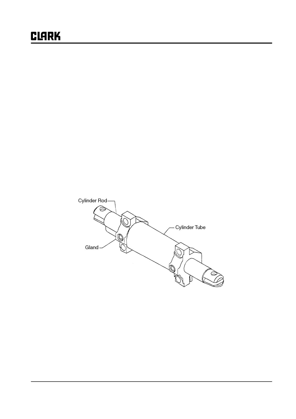
Group 26, Steer Axle
Section 6
Steer Cylinder Overhaul
Preparation for Steer Cylinder
Disassembly and Overhaul
2
Steer Cylinder Disassembly
2
Parts Inspection
2
Steer Cylinder Reassembly
3
Operational Pressure Test
4
IMPORTANT
Before removing any component for overhaul, make sure the
correct repair parts, seals, and gasket sets are available.
SM 765, Dec ’06
Steer Cylinder Overhaul • 26-6-1
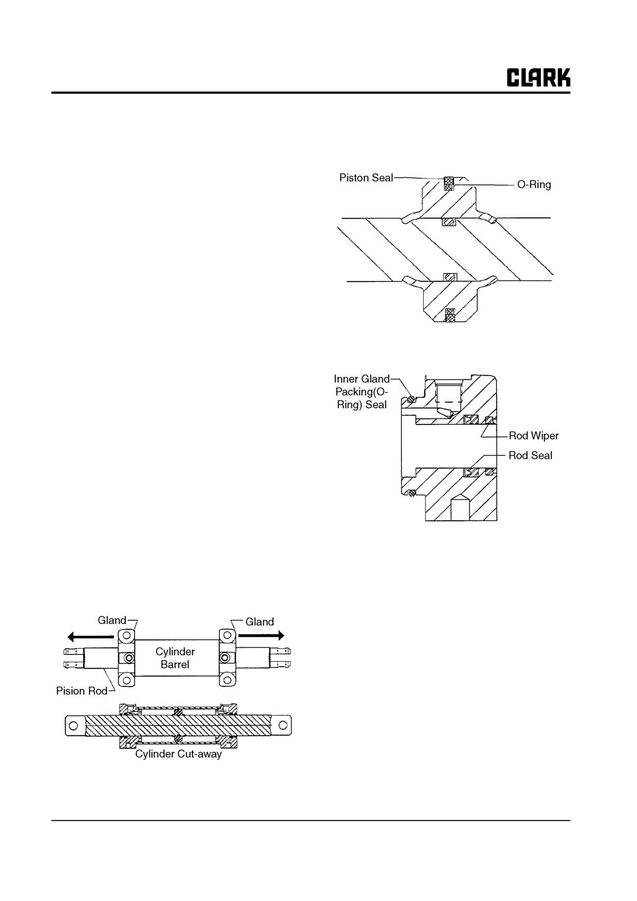
Group 26, Steer Axle
4.
Remove gland from opposite end of steer cylinder.
Preparation for Steer Cylinder Disas-
sembly and Over haul
5.
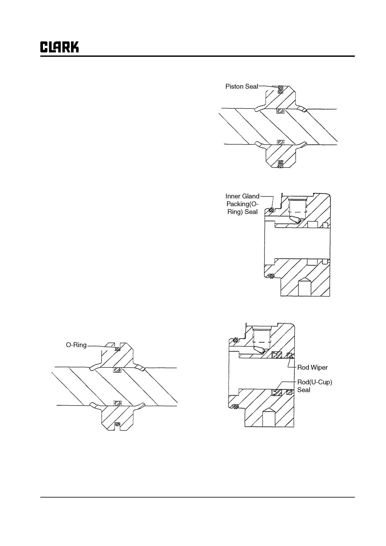
Remove the seal and O-ring set from the piston. Dis-
card seals. Replace with new seal set at assembly.
Refer to Section 5 for removal of steer cylinder from the
steer axle body.
IMPORTANT
Cleanliness is of extreme importance in the
repair and overhaul of this assembly.
1.
Overhaul steer cylinder only in a clean, dust-free
location, using clean tools and equipment. Dirt or grit
will damage the highly-machined surfaces and will
result in leakage or premature failure of components.
Cleanliness of the hydraulic circuit is extremely
important to the proper operation and maintenance of
the system. Be sure the work area is clean.
6.
Remove (inner) gland packing (O-ring) seal. Replace
2.
Before disassembly, the exterior of the steer cylinder
with new seals at assembly.
should be carefully cleaned to remove all dirt and
grease accumulation.
3.
Be sure all hydraulic fluid has been removed from
the cylinder. Stroking the piston rod will help force
the fluid out.
4.
Before starting disassembly, the steer cylinder should
be carefully examined to determine if there is any
external damage.
Steer Cylinder Disassembly
1.
Clamp the steer cylinder assembly in a vise. Wrap
the cylinder in a course cloth to prevent slipping and
scratching. Use extreme caution when tightening vise
7.
Remove the rod (U-cup) seal and rod wiper from
and do not overtighten; cylinder can be bent, dis-
gland and discard. Note direction of seal and wiper
torted, and potentially destroyed.
seating for correct reassembly. Replace with new
seals and wipers at assembly.
2.
Remove one gland by pulling it from cylinder barrel
and pulling it off the piston rod.
Parts Inspection
1.
Carefully clean all parts in an approved solvent and
place on a clean surface.
2.
Check the piston for chips, cracks, and looseness on
the rod. If loose, replace rod and piston assembly.
3.
Be sure the piston-seal groove in the piston is
smooth, true, and undamaged.
4.
Check the piston rod for damage. Look for scratches,
grooves, gouges, pitting, corrosion or other evidence
of unusual wear. Minor surface damage may be
repaired by use of fine abrasion cloth or stoning.
3.
Remove the piston and rod assembly from the Cylin-
Deeper damage will require replacement of piston
der.
rod assembly.
26-6-2 • Steer Cylinder Overhaul
SM 765, Dec ’06
Group 26, Steer Axle
5. Carefully inspect the cylinder internal bore for wear,
scratches, corrosion or other damage. Check the out-
side for damage. Inspect all welds for cracks.
6. Inspect the cylinder ports and threads to be sure they
are free of contamination and that the threads are
clean and not damaged.
7. Check the gland for cracks or damage that could
cause failure.
8. Deep gouges or pitted surfaces require replacement
of parts.
9. Put a light coating of hydraulic fluid on all parts. If
parts are to be left disassembled for a period of time,
3. Install new gland packing (O-ring) seal on inner end
such as overnight, they should be covered with a
of gland.
clean cloth.
Steer Cylinder Reassembly
Check to make sure the overhaul kit you have is correct
and that all parts are included.
IMPORTANT
Be sure inside of cylinder and all parts are
clean before starting reassembly.
Assemble cylinder carefully to prevent dam-
age to seal lips and O-rings. Seals should be
lubricated with hydraulic oil to assist assem-
bly into cylinder barrel and gland. Heating
seal rings in boiling water before starting
assembly will aid in assembly.
4. Install new rod wiper and rod (U-cup) seal in outer
end of gland.
1. Install new O-ring seal on the piston.
IMPORTANT
2. Install new piston seal over the O-ring seal.
Be sure the rod wiper and rod (U-cup) seal
are installed in the correct directions.
5. Lightly lubricate the cylinder and gland mating sur-
faces with hydraulic oil before assembly.
SM 765, Dec ’06
Steer Cylinder Overhaul • 26-6-3
Group 26, Steer Axle
6. Install the gland onto the cylinder bore rim, making
Operational Pressure Test
sure gland is fully seated on cylinder.
Once cylinder is remounted on axle (see Section 5), con-
7. Install piston and rod assembly into the cylinder.
nect pressure source in turn at each port. Extend piston
rod at each side and test with internal pressure of 13790
NOTE
kPa (2000 psi). At this pressure no leakage must occur.
A special part is included in the parts kit to
Typical operating pressure is 7585 kPa (1100 psi).
allow you to slip the gland over the rod end
without damaging the gland seals.
8. Repeat above procedure for installation of opposite
gland.
26-6-4 • Steer Cylinder Overhaul
SM 765, Dec ’06
Group 26, Steer Axle
Section 7
Pivot-Turn Steering Axle Maintenance
Specifications
2
Description
2
Wheel Bearing Check
4
Wheel Bearing Lubrication
4
Wheel Bearing Adjustment
7
Steer Axle Disassembly
7
Part Inspection
9
Steer Axle Reassembly
9
SM 765, Dec ’06
Pivot-Turn Steering Axle Maintenance • 26-7-1
Group 26, Steer Axle
Specifications
Service Intervals
Steering System Relief Pressure Setting : 10000 kPa
Steering Linkage Inspection and Lubrication: Every 50-
(1450 psi)
250 hours and each PM.
Steer Cylinder Type : Double-acting, piston-type
Steer Wheel Bearing Inspection and Lubrication: Every
50-250 hours of operation.
Turning Arc : 100° maximum inside turning angle
75° maximum outside turning angle.
Steer Cylinder Seals Leakage Check: Every 50-250 hours
and each PM.
Bearing Grease : Grade No. 2 EP multi-purpose grease,
Clark Part MS-107C.
Steer Axle Mounting Inspection: Every 50-250 hours and
each PM.
Fastener Torques
Power Steering Relief Pressure Check: Every year or 2000
hours of operation.
Steer Axle Mounting Bolts: 240-270 N⋅m (177-200 ft-lb)
Cylinder to Axle Mounting Bolts: 100-110 N⋅m (74-81 ft-
Description
lb)
The steer axle has the steer cylinder, steer knuckles, and
Steering Link to Steering Knuckle Nuts: 135-150 N⋅m
steering links mounted on it. All these components can be
(98-110 ft-lb)
removed, serviced, and replaced.
The steering gear (steering control unit) at the base of the
steering column directs hydraulic fluid to one end or the
other of the steer cylinder to pivot the steer wheels.
The steer axle is bolted to the truck frame. The steer cylin-
der is connected to the steering knuckles by steer links.
Mounting trunnions allow the axle to tilt independently of
the truck and “silent” mounts cushion the axle on the trun-
nions.
All bearings used in the steer axle linkage have lubrication
fittings and are serviceable. Axle removal, replacement,
and service for all components, including overhaul of the
steer cylinder, is explained in the Sections for this Group.
26-7-2 • Pivot-Turn Steering Axle Maintenance
SM 765, Dec ’06
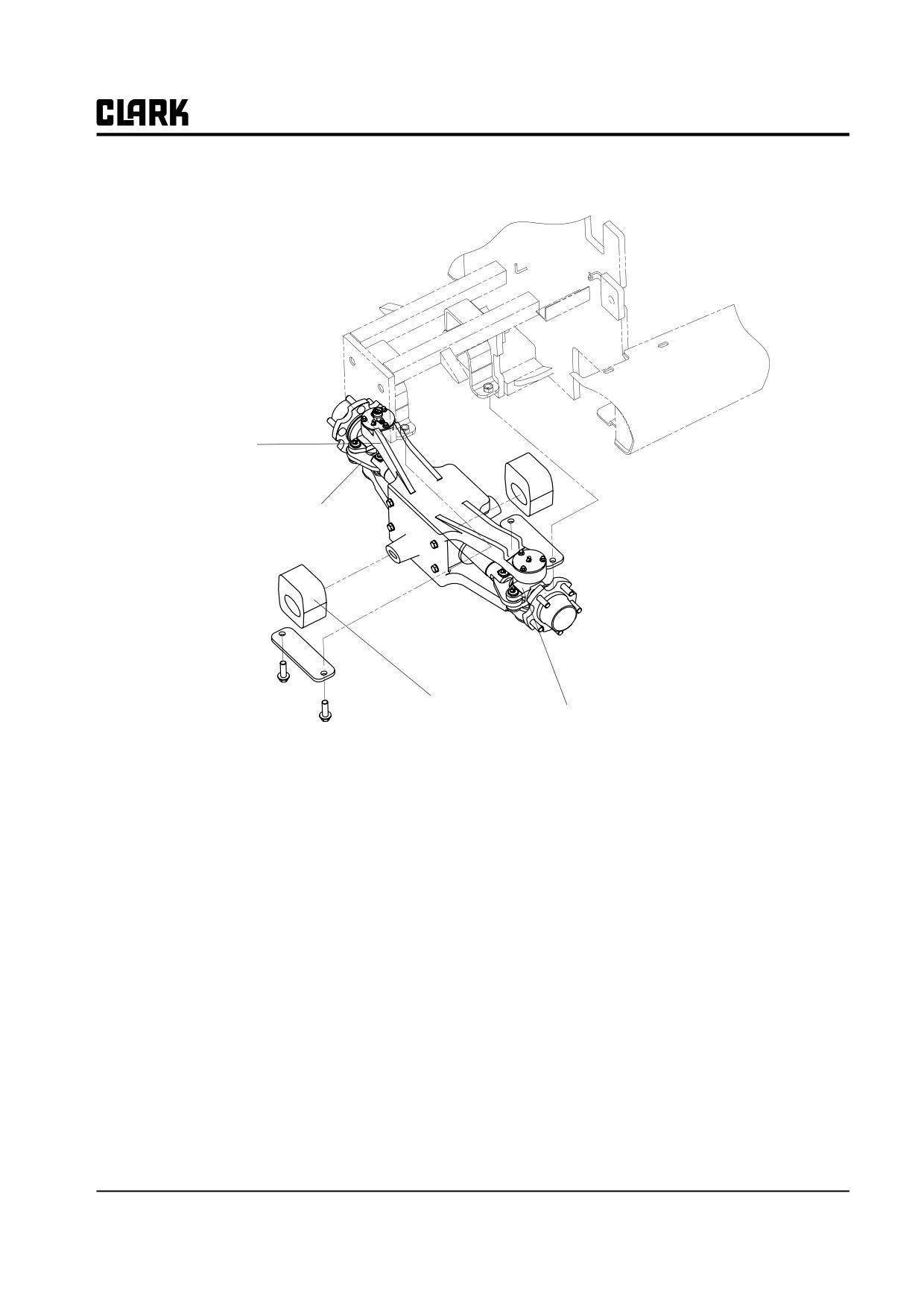
Group 26, Steer Axle
Steer Axle
Steering Link
Silent Mount
Steering Knuckle
Steer Axle and Mounting
SM 765, Dec ’06
Pivot-Turn Steering Axle Maintenance • 26-7-3
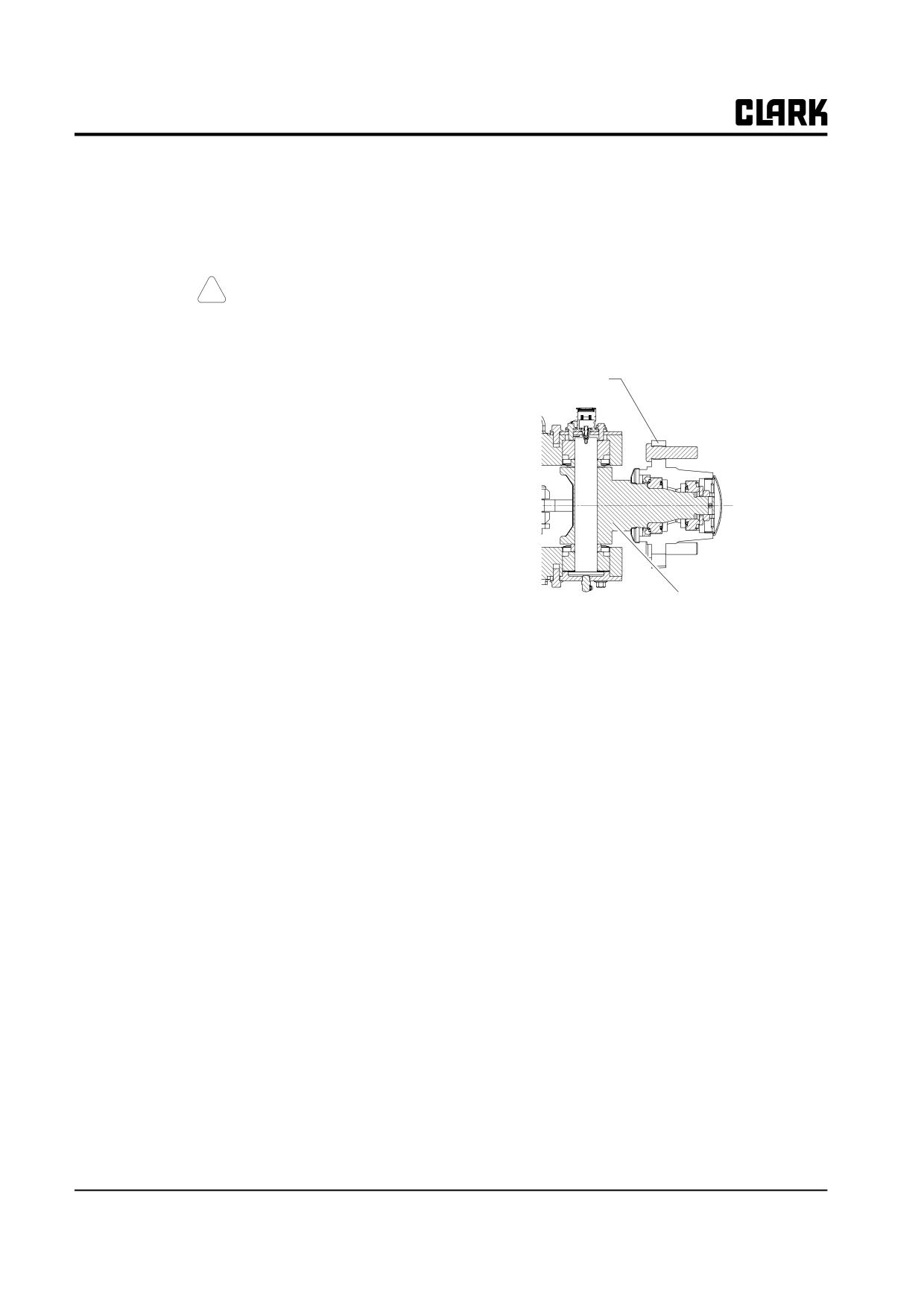
Group 26, Steer Axle
IMPORTANT
Wheel Bearing Lubrication
Before removing any component for over-
These procedures cover bearing lubrication for steer
haul, make sure the correct repair parts,
wheels used on the truck ; pneumatic-tire wheels which
seals, and gasket sets are available.
are mounted on a hub that contains the bearing compo-
nents. Use the procedures to clean, repack and adjust bear-
! CAUTION
ings for both the pneumatic-tire hub.
The bearing components and arrangement are the same
SAFE PARKING. Before working on truck:
for both the pneumatic types. Instructions for repacking/
1. Park truck on a hard, level, and solid
lubricating the bearing components apply to both types.
surface, such as a concrete floor with no
gaps or breaks.
Pneumatic-Tire
Wheel Mounting
2. Put upright in vertical position and fully
Hub
lower the forks or attachment.
3. Put all controls in neutral. Turn key
switch OFF and remove key.
4. Apply the parking brake and block the
wheels.
5. Remove Battery Connector.
Wheel Bearing Check
Wheel bearings check should be performed every PM.
Steer Axle Knuckle
Wheel bearings need adjustment only after 2000 hours or
wheel-assembly
as needed. It is recommended that you clean and repack
the bearings before adjustment. Check hourmeter total
hours and refer to the truck’s PM schedule. See steer
wheel bearing lubrication procedure below.
To check the steer wheel bearings for excessive free play
or looseness:
1. Grasp the wheel with both hands and try to move it
by a rocking motion top-to-bottom.
2. Try to pull it in and out along the wheel spindle.
Watch for excessive free movement in wheel bearings or
steering knuckle bearings. There should be a small
amount of free movement. If the wheel has excessive free
movement, the bearings require additional service and/or
adjustment.
26-7-4 • Pivot-Turn Steering Axle Maintenance
SM 765, Dec ’06
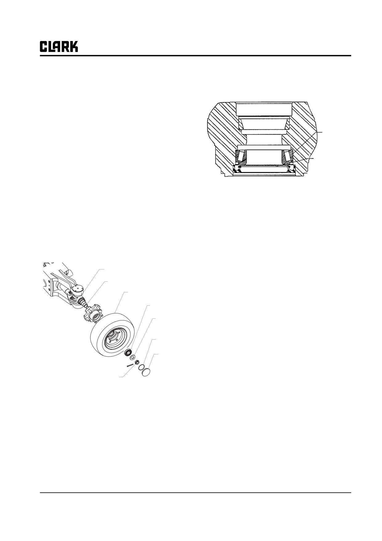
Group 26, Steer Axle
Bearing Disassembly
a brass drift pin, rod, or piece of pipe to drive the
bearing and seal out of the hub.
1.
Be sure truck is parked and blocked up correctly and
safely to raise steer wheels off the floor. Refer to
“Lifting, Jacking, and Blocking,” in the Group “SA.”
NOTE
Because of the heavy weight of the wheel and
Bearing &
tire, it is suggested to first remove the wheel
Cone
and tire assembly from spindle when servic-
ing the bearings to avoid damage to the
grease seal when the wheel hub is moved off
Grease Seal
or on the spindle. It also makes the work sim-
pler and easier.
2.
Refer to the exploded view illustration of the wheel
8.
Clean and inspect the bearing cups and cones for
bearing assembly. Loosen and remove the hubcap
wear or other damage. Replace, as necessary.
from wheel or hub. You may have to lightly tap hub
IMPORTANT
cap with a hammer and chisel and use a pry bar to
loosen. Be careful not to damage mounting surfaces.
Keep serviceable bearing cups and cones
Remove O-ring from hubcap.
matched together. Always replace bearing
cups and cones as a set.
3.
Clean the excess grease from around the wheel nut.
4.
Remove cotter pin, loosen and remove wheel nut and
9.
Inspect grease seal for wear and damage. Replace as
necessary. It is recommended to install a new grease
bearing washer.
seal whenever old ones are removed.
Steering Axle Knuckle
10.
Use a standard puller to remove bearing cups from
Spindle
hub or wheel if bearings require replacement.
Tire and Whel
Bearing
Bearing
Washer
O-ring
Hub cab
Wheel nut and
Cotter pin
Wheel Bearing Assembly.
5.
Pull the wheel or hub off the spindle. Support the
wheel or hub to avoid dragging the grease seal at the
back side across the thread on spindle end.
6.
Clean the old grease out of center of the wheel or
hub.
7.
To remove inner bearing and seal, lay wheel or hub
down with outer edge up (support hub on blocking).
Remove the inner bearing cone and grease seal, using
SM 765, Dec ’06
Pivot-Turn Steering Axle Maintenance • 26-7-5
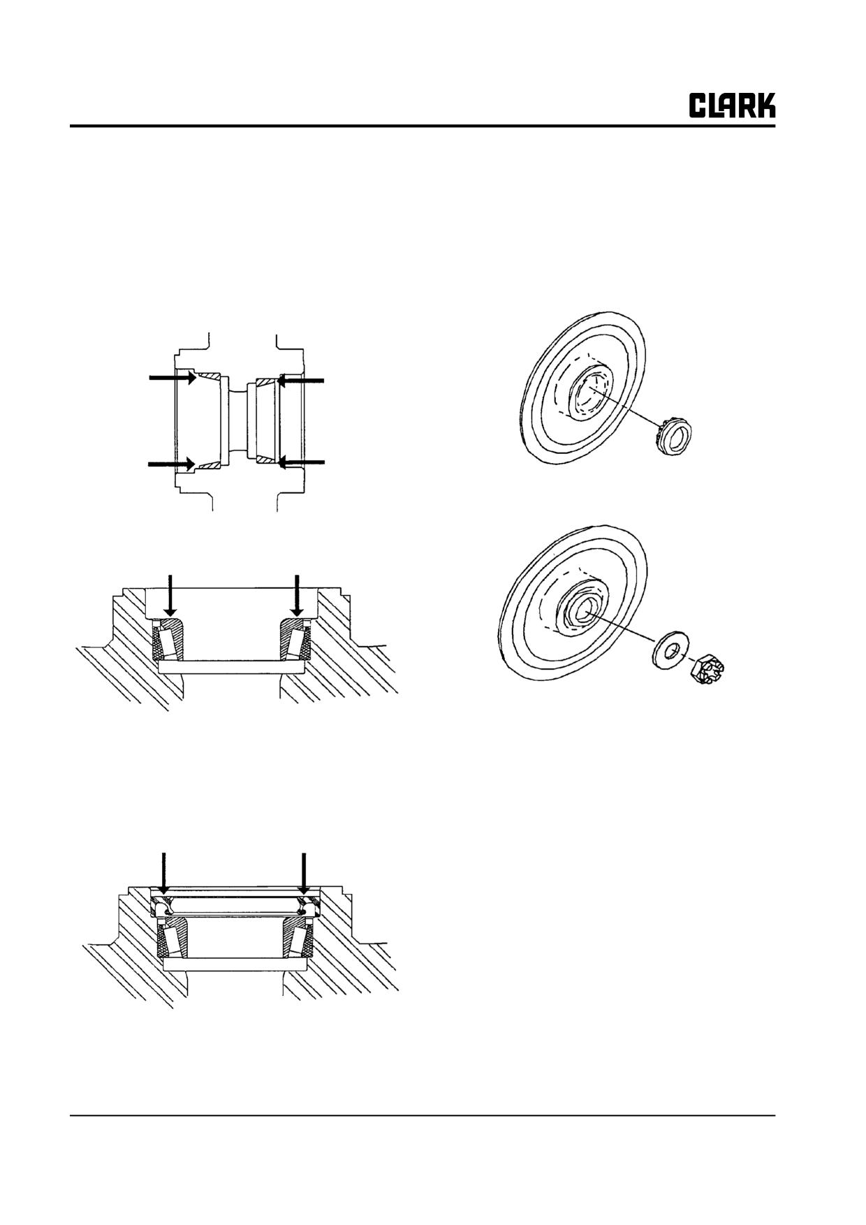
Group 26, Steer Axle
Bearing Reassembly
6. Install hub or wheel on spindle. Be careful not to
damage grease seal lip when moving the hub over the
NOTE
end of spindle and threads.
Use Grade No. 2 EP multi-purpose grease,
7. Pack cavity in hub between bearings one-half full
Clark MS-107C.
with grease.
1. Install new inner and outer bearing cups by pressing
8. Install the outer wheel bearing after it has been
into hub or wheel. Be sure cups are fully seated in
packed with grease.
bore.
9. Install bearing washer and hand tighten wheel nut.
2. Pack the bearings with grease and install the inner
bearing in the hub or wheel.
10. Rotate hub or wheel counter clockwise and torque
wheel nut to 27-31 N⋅m (20-23 ft-lb).
3. Pack cavity between bearing and grease seal half full
11. Back wheel nut up until it is loose.
with grease.
12. While turning the hub or wheel counter clockwise,
4. Install new grease seal in hub or wheel inner bore.
torque the wheel nut to 2.3-2.8 N⋅m (1.7-2 ft-lb).
Apply coating of grease to inside diameter of seal
lips prior to assembly, then install seal in hub or
13. Back up wheel nut to nearest slot and install new cot-
wheel bore.
ter pin. Bend cotter pin tabs.
14. Recheck for correct bearing adjustment by rotating
the wheel by hand. Wheel should rotate freely or
with only slight “drag”. Readjust bearings by adjust-
ing wheel nut as necessary to avoid binding in bear-
ings.
15. Pack the area around wheel nut with grease.
5. Carefully press or tap grease seal into place with
asoftfaced mallet until seal is seated in bottom of
bore.
26-7-6 • Pivot-Turn Steering Axle Maintenance
SM 765, Dec ’06
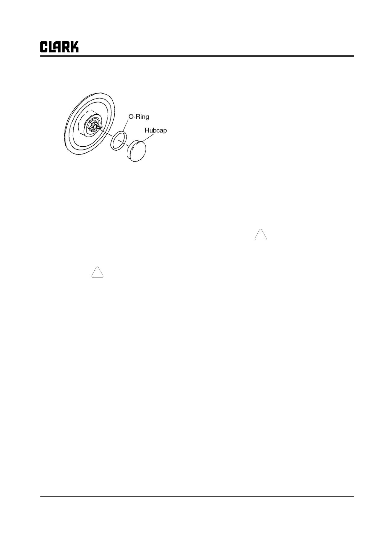
Group 26, Steer Axle
16. Refit O-ring on hubcap and install hubcap by tapping
10.
Recheck for correct bearing adjustment by rotating
into place with a rubber or plastic-faced hammer.
the wheel by hand. Wheel should rotate freely or
with only slight “drag”. Readjust bearings by adjust-
ing wheel nut as necessary to avoid binding in bear-
ings.
11.
Bend cotter pin tabs over.
12.
Pack the area around wheel nut with grease.
13.
Refit O-ring on hubcap if removed or replaced and
install hubcap by tapping into place with a rubber or
plastic-faced hammer.
Steer Axle Disassembly
Wheel Bearing Adjustment
IMPORTANT
The steer wheel bearings are retained and adjusted by the
wheel nut.
Before removing any component for over-
haul, make sure the correct repair parts,
NOTE
seals, and gasket sets are available.
You should clean and repack the wheel bear-
ings before performing a wheel bearing
adjustment. See “Wheel Bearing Lubrica-
!
CAUTION
tion” in this Section for the complete proce-
SAFE PARKING. REFER TO PAGE 3.
dure.
NOTE
Cleanliness is of extreme importance in the
! CAUTION
repair and overhaul of this assembly.
SAFE PARKING. REFER TO PAGE 3.
• Before starting disassembly, thoroughly clean the
1.
Make sure the truck is parked on a level, hard sur-
axle assembly of all accumulations of dirt, oil, cor-
face, the upright is fully lowered, the drive wheels
rosion, and other substances to prevent contamina-
are chocked, and the steer wheels are jacked and
tion of the parts during disassembly and overhaul.
blocked securely. Refer to “Lifting, Jacking, and
• Work in a clean area.
Blocking” for safe procedures.
• Keep all parts in order as disassembly progresses.
2.
Remove hubcap.
Take care to properly identify each part and its
3.
Remove and discard cotter pin.
order of removal. If necessary, keep notes and put
markings on parts using a non-destructive marker
4.
Loosen wheel nut.
such as a grease pencil or felt-tipped pen.
5.
After wheel nut is loosened, hit the top of wheel to
• If necessary, see Section 3, “Steer Axle Removal
loosen the bearings. This moves the bearings free of
and Replacement,” for the procedures to remove
their seated, running position.
the steer axle from the truck.
6.
Rotate hub or wheel counter clockwise and torque
• See Section 5, “Steer Cylinder Removal and
wheel nut to 27-31 N⋅m (20-23 ft-lb).
Replacement,” for the procedures to remove the
steering cylinder and steering links from the steer
7.
Back wheel nut up until it is loose.
axle.
8.
While turning the hub or wheel counter clockwise,
• See Section 6, “Steering Cylinder Overhaul,” to
torque the wheel nut to 2.3-2.8 N⋅m (1.7-2 ft-lb).
disassemble the steer cylinder.
9.
Back up wheel nut to nearest castellation slot and
install new cotter pin.
SM 765, Dec ’06
Pivot-Turn Steering Axle Maintenance • 26-7-7
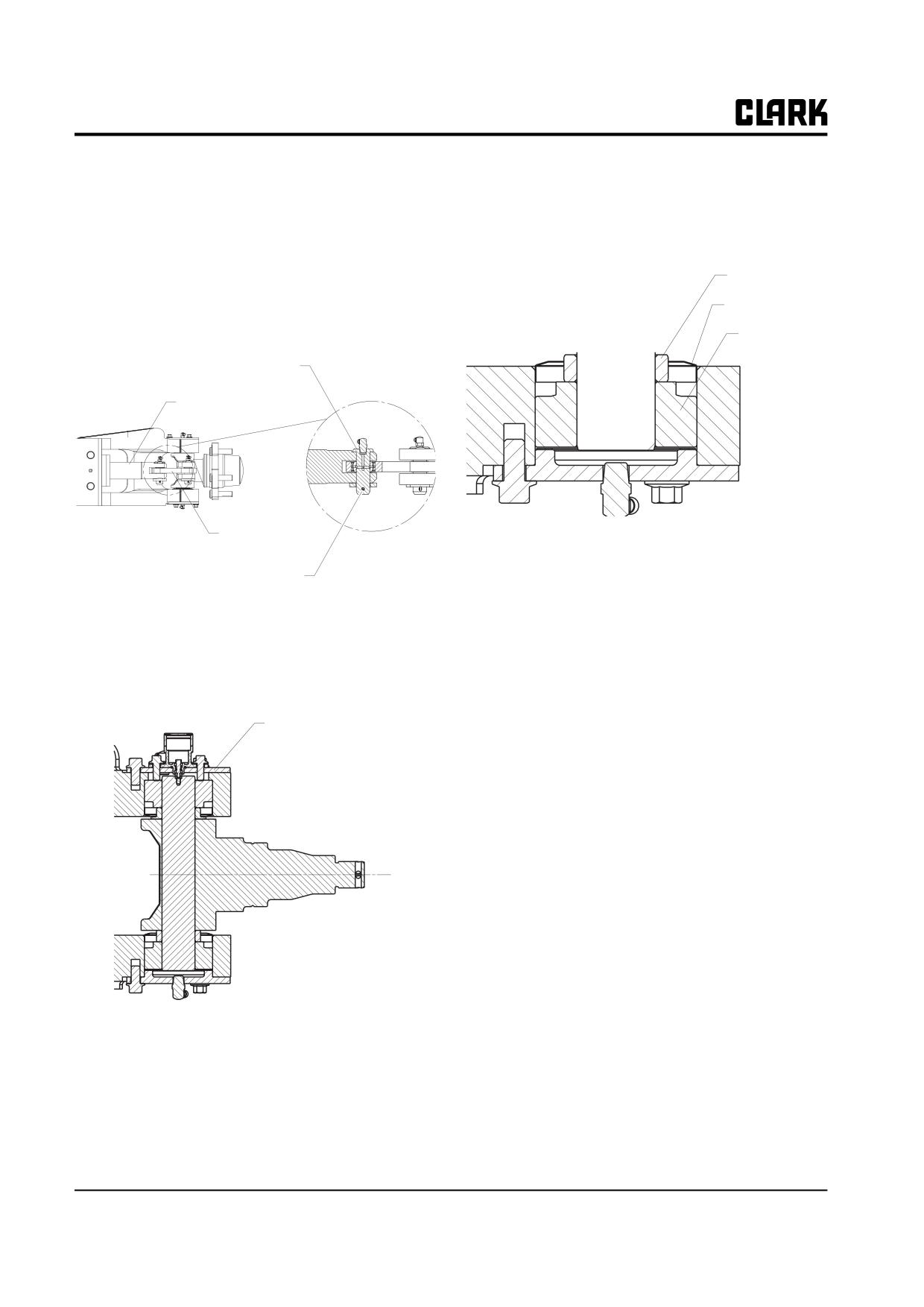
Group 26, Steer Axle
To disassemble the steering knuckle, kingpin, and bearing
5. Remove the knuckle bearing washers, dust covers,
from the steer axle, it is not necessary to remove the axle
upper and lower grease seals and bearings from the
from the truck.
assembly.
1. Remove the cotter pin and washer from the bottom of
the steering link pin and remove the pin. Steering
Spacer
link is free to be removed from the cylinder rod and
knuckle.
Grease Seals
Bearing
Steering Link Pin
Cylinder Rod
Steering Link
Bearing cups may be removed by hand, by using a bearing
puller, or by tapping out using a brass drift pin.
Cotter Pin
2. Remove the stop bolts from the steering knuckle.
3. Remove the bearing protection covers which lie over
and under the steering knuckle. Don’t remove the
bearing cap.
Bearing Cover
4. Drive the kingpin down and out of the assembly.
Remove the steering knuckle. Note right and left
knuckle parts.
IMPORTANT
Do not let the knuckle or pin fall when the
pin is removed.
26-7-8 • Pivot-Turn Steering Axle Maintenance
SM 765, Dec ’06
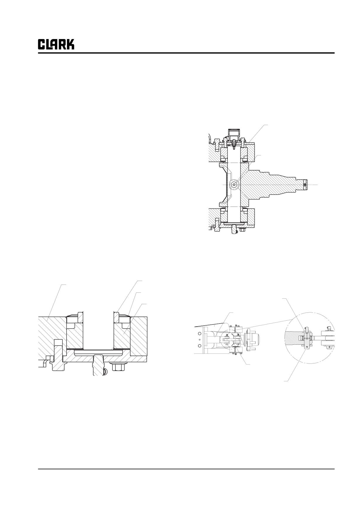
Group 26, Steer Axle
3.
Put the King pin on the steering axle/knuckle bore.
Parts Inspection
4.
Tighten the stop bolt to the center hole of the King
1. Clean all bearings, cups, seals, pins, and other parts
pin.
in an approved cleaning fluid.
IMPORTANT
2. Inspect all parts for scratches, chips and wear. Check
Make sure that retainer pin enters the hole in
the steering arms of the knuckles to be sure they are
the underside of the axle
not bent or twisted. Check all threaded parts for dam-
age.
Bearing Cover
3. Replace all parts which show damage.
4. If parts are to be left exposed, coat all mating sur-
faces of parts with a light coating of engine oil.
Center Hole
Steer Axle Reassembly
Recommended greasing procedure:
a. Use Grade No. 2 EP multi-purpose grease, Clark
MS-107 or equivalent.
b. Pack all tapered roller bearings with grease
before assembly.
c. Pack knuckle pin (bearing) seals with grease
before assembly.
d. Fill steer link sockets with grease through grease
5.
Adjust the height of steering knuckle by use of shim,
fittings after axle is assembled.
so that the steering knuckle can be slightly rotated.
6.
Tighten the bearing protection covers above and
1. Install the bearing cup to the axle housing bore. Tap
under the axle housing.
into place with a brass drift pin or equivalent.
7.
Replace steering link pin and snap ring to join the
Spacer
cylinder rod to the steering link and knuckle.
Axle Housing
Grease Seals
Steering Link Pin
Bearing
Cylinder Rod
Steering Link
Cotter Pin
IMPORTANT
Make sure that bearing cup is fully seated
against the shoulder in bore. There must be
no gap left between cup and the shoulder in
the bore at assembly.
2. Apply grease to upper and lower knuckle bearings
and install bearings, grease seals, and washers to
bores of axle housing.
SM 765, Dec ’06
Pivot-Turn Steering Axle Maintenance • 26-7-9
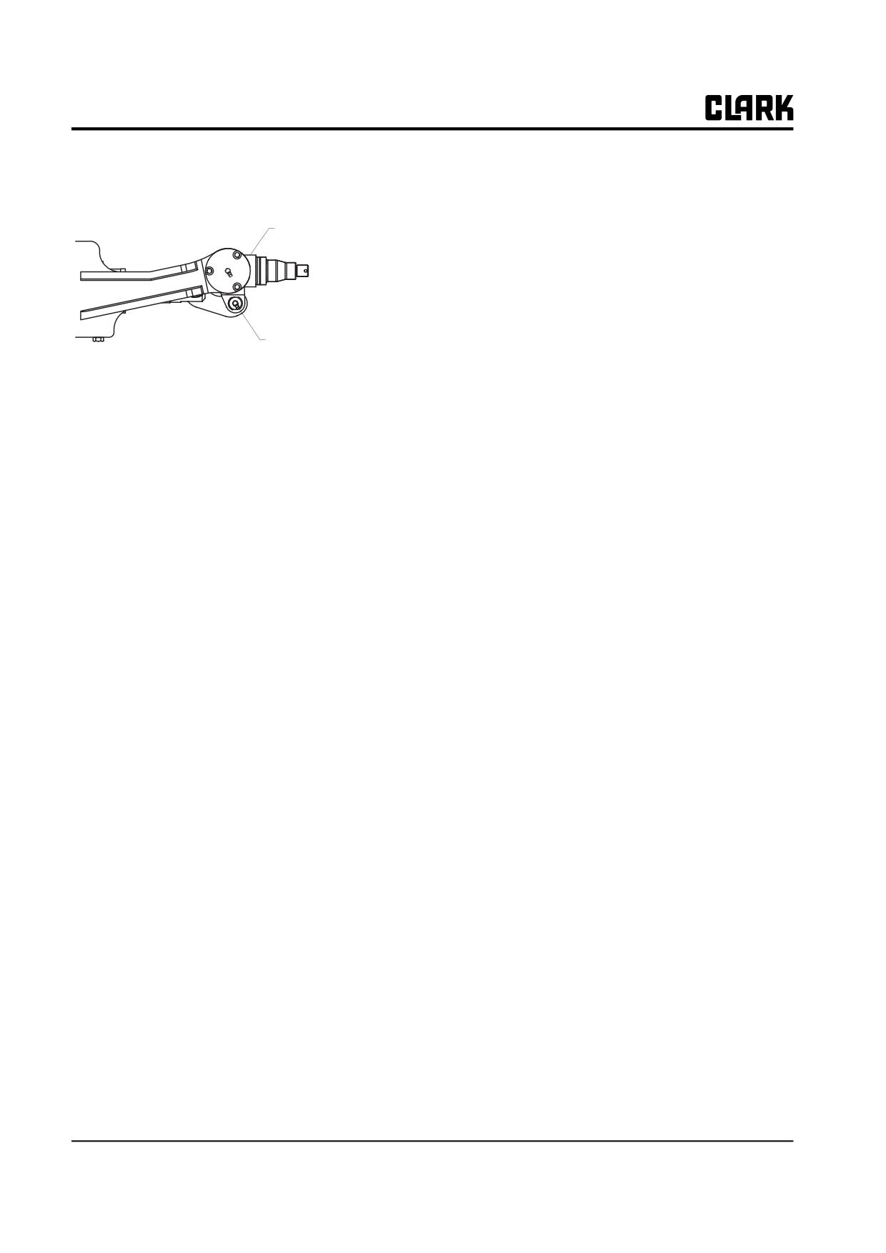
Group 26, Steer Axle
8. Reinstall grease fitting in knuckle housing and lubri-
cate with recommended grease.
Knuckle
Housing
Grease fitting
26-7-10 • Pivot-Turn Steering Axle Maintenance
SM 765, Dec ’06
GROUP 29
GROUP 29
HYDRAULIC SUMP, FILTERS, AND PUMP
Main Hydraulic Sump, Filters, and Pump
Specifications and Description
Section 1
Main Hydraulic Pump Troubleshooting
Section 2
Main Hydraulic Pump Removal and Installation Section 3
NOTE
This group covers the main hydraulic pump for the load
handling system.
Other hydraulic-related components and circuits are
described and illustrated in Group 25 “Steering Column and
Gear,” Group 26 “Steering System,” Group 30 “Hydraulic
Control Valve/Lift Circuit,” Group 32 “Tilt Cylinders,” and
Group 34 “Uprights.” Refer to these groups for hydraulic
components not covered in this group.
SM 765, Nov ’06
Group 29, HYDRAULIC SUMP, FILTERS, AND PUMP
NOTE :
Group 29, HYDRAULIC SUMP, FILTERS, AND PUMP
SM 765, Nov ’06
Group 29, Hydraulic Sump, Filters, and Pump
Section 1
Main Hydraulic Sump, Filters, and Pump
Specifications and Description
Specifications
2
Service Intervals
2
System Description
2
Sump Tank Fill Levels
4
Hydraulic Fluid and Filter Change
5
Remove, clean and replace the strainer
5
SM 765, Nov ’06
Main Hydraulic Sump, Filters, and Pump Specifications and Description • 29-1-1
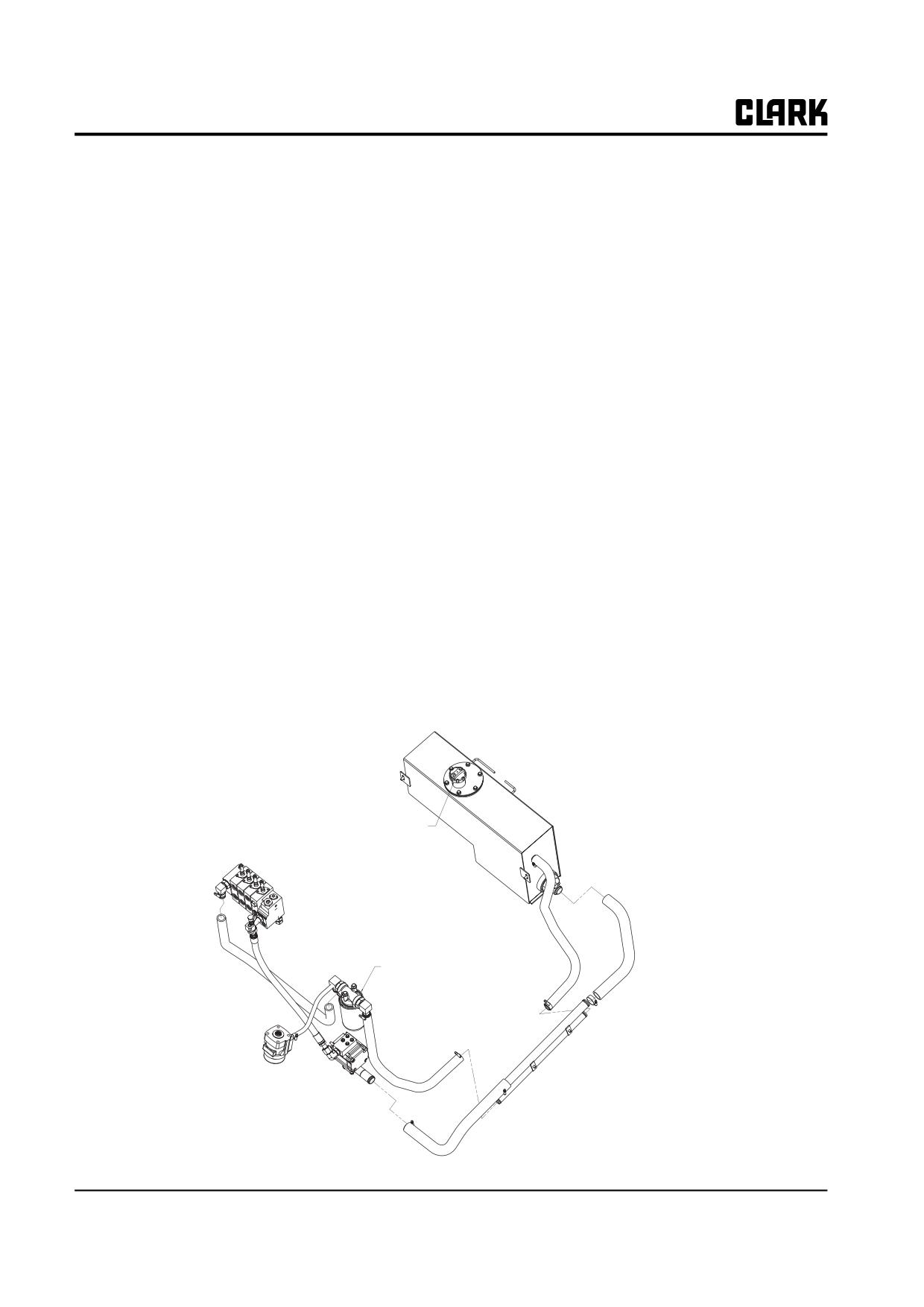
Group 29, Hydraulic Sump, Filters, and Pump
The hydraulic sump is located in the rear side compart-
Specifications
ment of the truck frame. The sump is equipped with a suc-
Hydraulic Pump Type: IntegraI gear-type pump and motor
tion line screen, return line filter, filter cap/breather.
assembly.
The hydraulic pump and motor assembly is mounted to
Sump Capacity: Usable oil = 24 Litres (6.3 Gal)
the flow plate.
Hydraulic Fluid Type: Clark Hydraulic Fluid MS-68 (or
The hydraulic pump draws oil from the sump and sends
other specification MS-68).
oil to main valve.
Filter Type: Disposable, 25 micron, return line oil filter,
The oil which was supplied from the main valve to the
100 mesh suction line screen and a 10 micron filter cap/
steering unit and attachment returns to sump.
breather filter.
Serviceable items are the pump, motor, suction line screen
and the return line filter. Other components, such as hoses,
Service Intervals
fittings, and clamps, are nonserviceable and should be
replaced if worn or damaged.
Hydraulic Fluid Level Checks: Every 8-10 hours or daily.
Hydraulic Fluid Change (Drain and Refill): Every 2000
hours of operation or every year.
Hydraulic Fluid Filter Replacement: After the first 50
hours of operation, then every year or 2000 hours of oper-
ation.
Description
NOTE
Se group 30 for a description of the complete
hydraulic circuit.
Sump Breather Cap
Return line Filter
29-1-2 • Main Hydraulic Sump, Filters, and Pump Specifications and Description
SM 765, Nov ’06
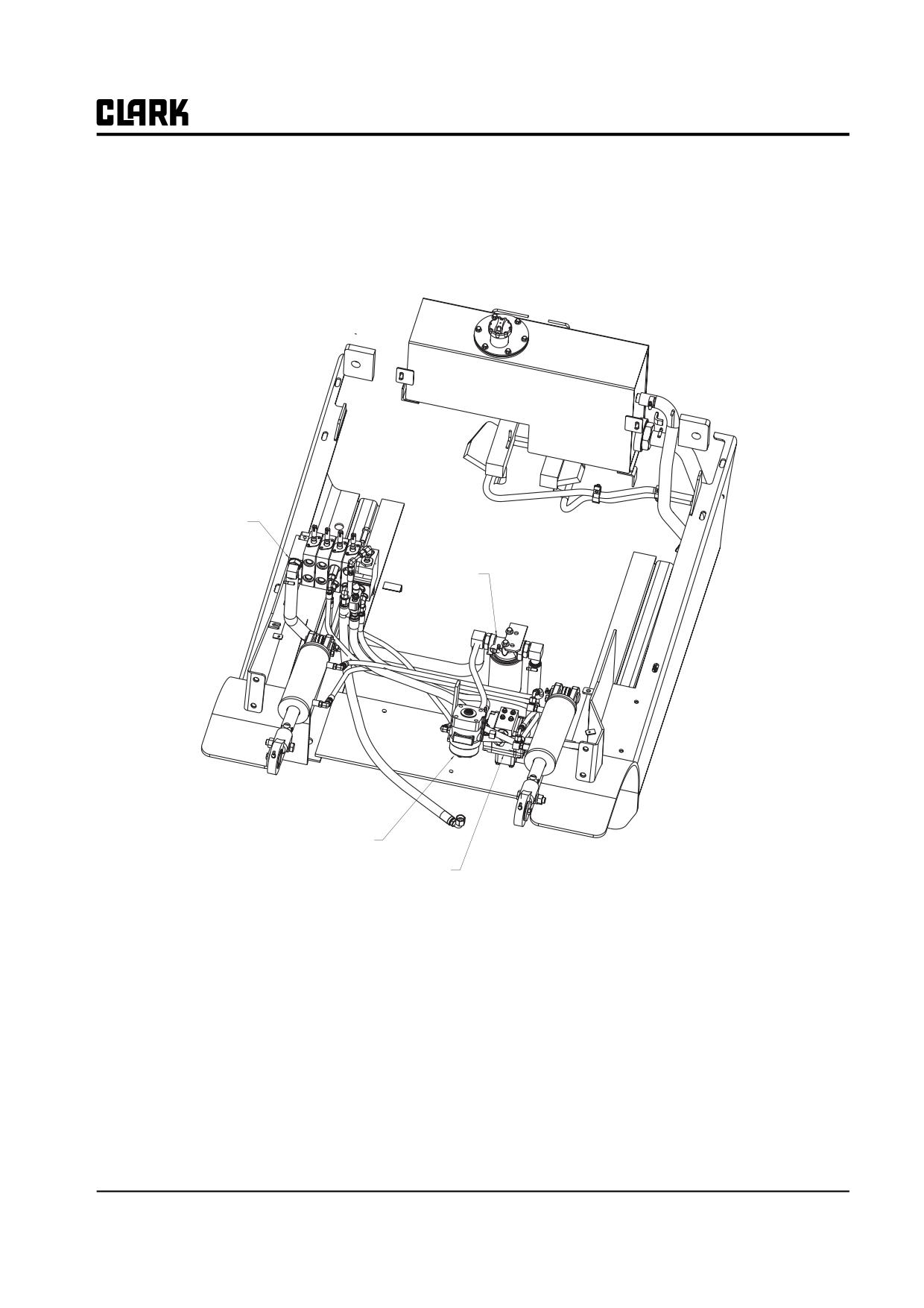
Group 29, Hydraulic Sump, Filters, and Pump
Control Valve
Filter
Steering Gear
Pump
SM 765, Nov ’06
Main Hydraulic Sump, Filters, and Pump Specifications and Description • 29-1-3
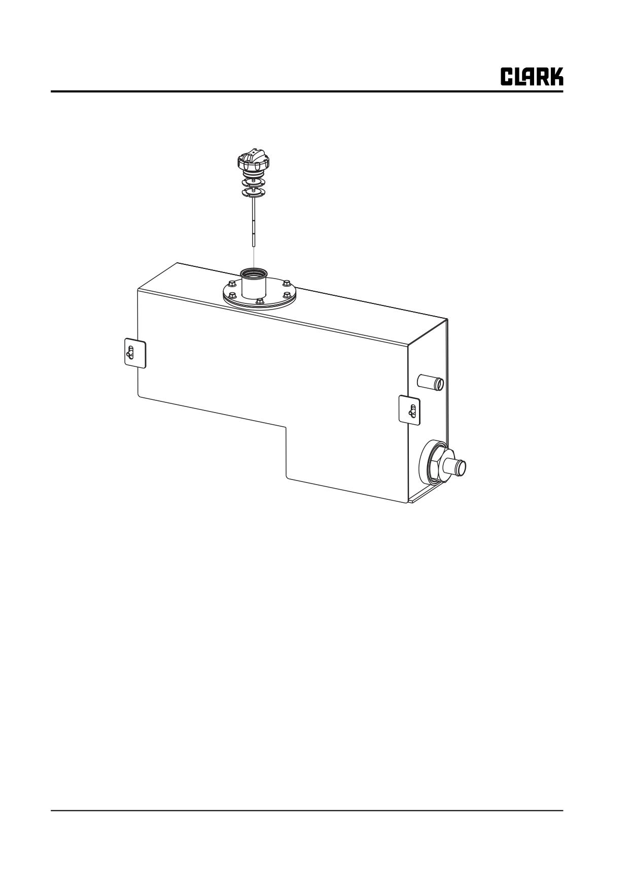
Group 29, Hydraulic Sump, Filters, and Pump
Sump Tank Fill Levels
Pull out the dipstick for the hydraulic oil.
29-1-4 • Main Hydraulic Sump, Filters, and Pump Specifications and Description
SM 765, Nov ’06
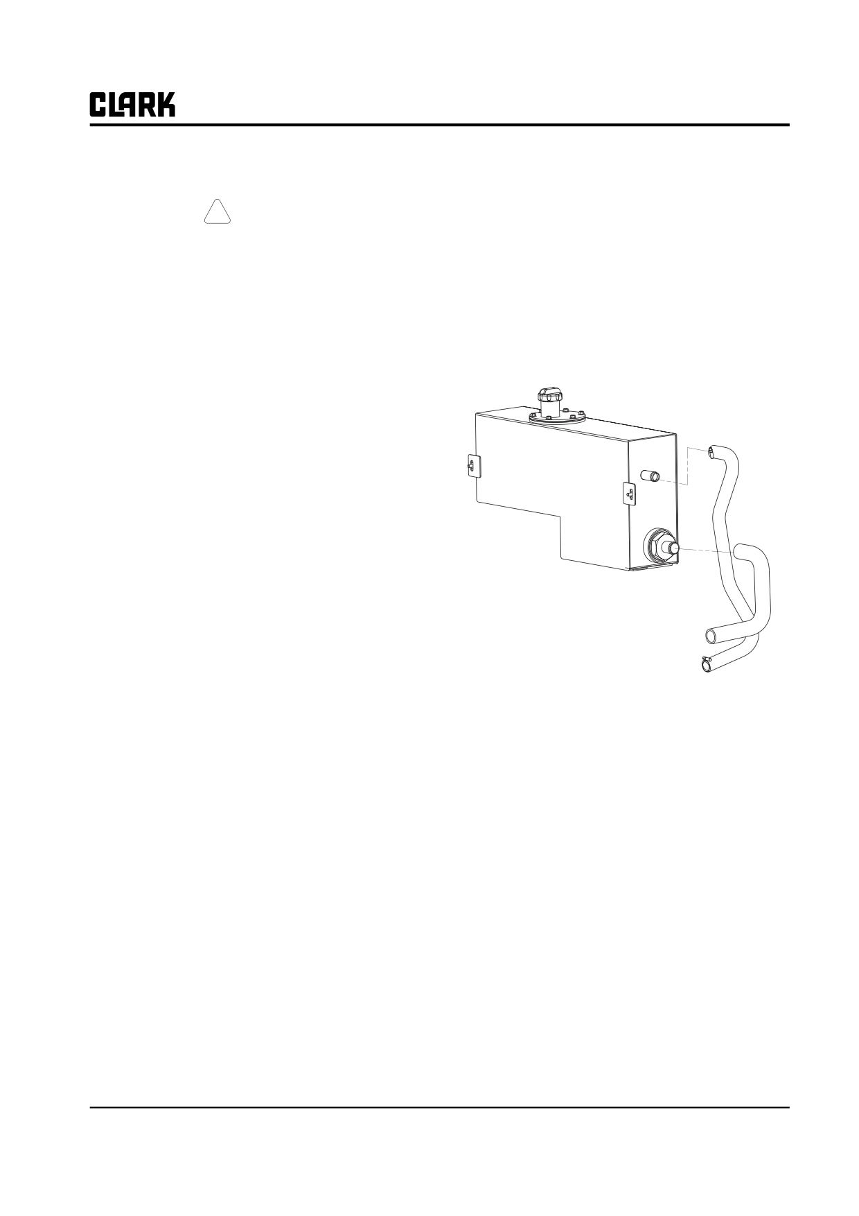
Group 29, Hydraulic Sump, Filters, and Pump
Hydraulic Fluid and Filter Change
Disconnect drain line from truck.
NOTICE
! CAUTION
If old oil is excessively dirty or hydraulic sys-
tem is contaminated, it is recommended that
SAFE PARKING. Before working on truck:
the sump tank be completely drained by
1. Park truck on a hard, level, and solid
removing the pump suction line from the
surface, such as a concrete floor with no
sump outlet and flushed withy clean oil.
gaps or breaks.
2. Put upright in vertical position and fully
Remove, clean and replace the strainer.
lower the forks or attachment.
3. Put all controls in neutral. Turn key
switch OFF and remove key.
4. Apply the parking brake and block the
wheels.
There is drain plug in the hydraulic sump tank. When the
sump tank must be drained of all fluid, the procedure is to
remove the drain plug and allow the fluid to drain into a
suitable drain pan. Unless the sump tank is to be removed
for other repair or maintenance, the hydraulic fluid can
also be changed by one of the following methods:
Pressure gauge to the diagnostic check port fitting.
NOTE: Use quick-disconnect adapter fitting.
You will need a drain pan of 24 L (6.3 gal) minimum
capacity. Be sure the outlet end of the drain line is directed
into the drain pan and held from moving when pressur-
ized.
Remove and discard old oil filter. Install new filter. Follow
the installation instructions printed on the filter body.
Turn key switch ON.
Move tilt control lever to the back tilt position to start the
lift pump. Hold tilt lever in this position until sump tank is
emptied. A steady stream of used oil should flow from the
drain line.
Continue operation until the sump tank is emptied. This
point will be reached when the pump starts to cavitate.
When cavitation occurs the pump speed will increase and
the speed sound will whine. Release the tilt lever immedi-
ately when pump cavitation occurs.
IMPORTANT
Be careful when sump is nearly emptied and
oil flow becomes erratic as the pump
approaches cavitation Do not operate pump
after cavitation occurs.
Turn the key switch OFF.
SM 765, Nov ’06
Main Hydraulic Sump, Filters, and Pump Specifications and Description • 29-1-5
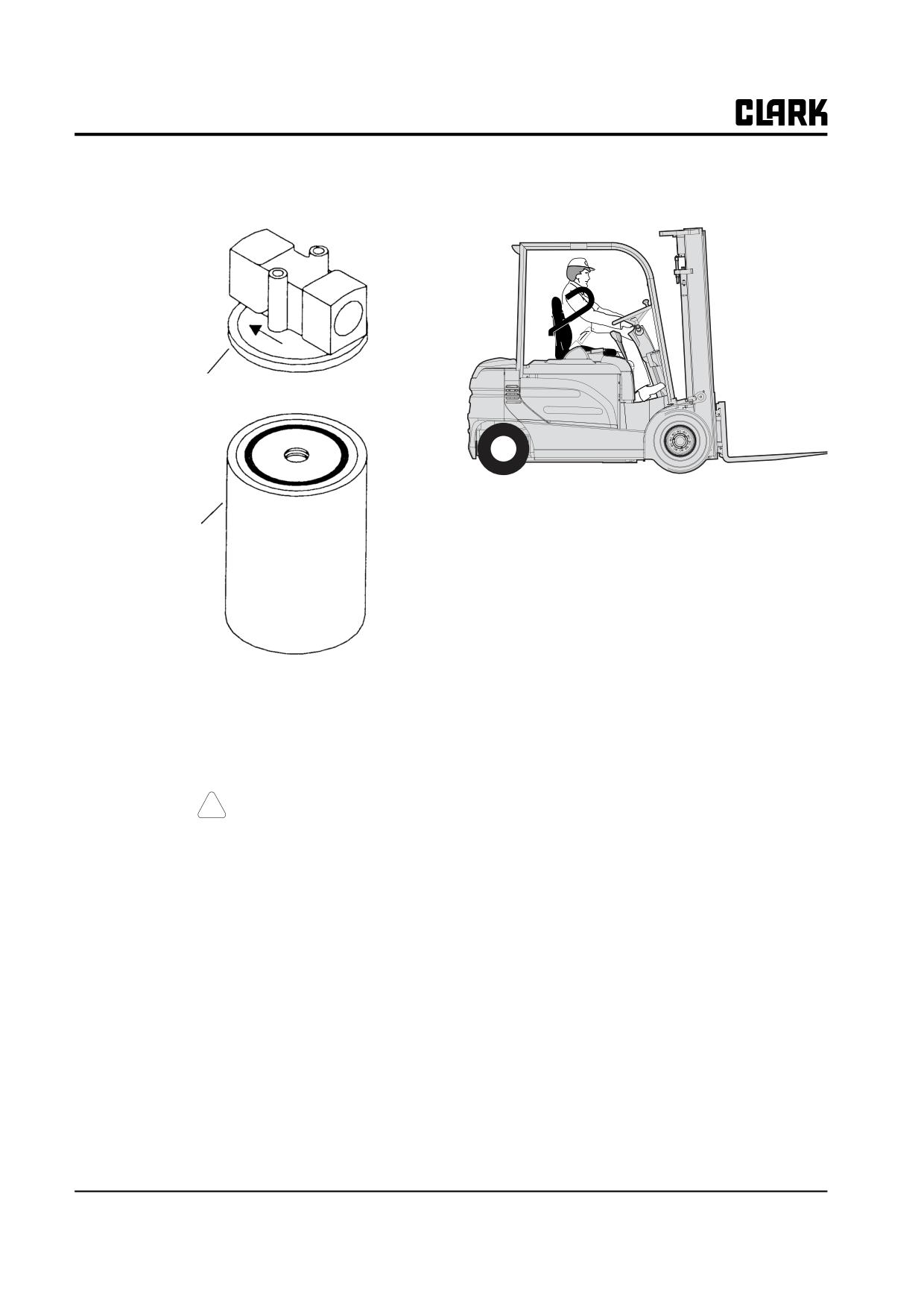
Group 29, Hydraulic Sump, Filters, and Pump
Also, check that the hydraulic line connections at the filter
head are tightened correctly.
Filter Head
Turn the key switch OFF.
Filter
Refill the sump tank with Clark MS-68 Hydraulic Fluid.
Check truck operation. Turn key switch ON. Operate the
hydraulic system. Cycle the lift system serval times: raise
the lift carriage to full height and lower fully down. Check
for leaks. Recheck sump tank fluid level.
! CAUTION
Be sure there is adequate overhead clearance
before raising upright.
29-1-6 • Main Hydraulic Sump, Filters, and Pump Specifications and Description
SM 765, Nov ’06
Group 29, Hydraulic Sump, Filters, and Pump
Section 2
Main Hydraulic Pump Troubleshooting
Noisy Pump
2
Pump Not Delivering Hydraulic Fluid
2
Failure to Build Pressure
2
Pump Not Developing Sufficient Pressure
2
Pump Output Low
2
Foaming Fluid
2
Overheated Pump and/or Fluid
2
External Leakage
3
SM 765, Nov ’06
Main Hydraulic Pump Troubleshooting • 29-2-1
Group 29, Hydraulic Sump, Filters, and Pump
The following is a list of problems and solutions relating
Pump Not Developing Sufficient
to the main hydraulic pump and associated components.
Pressure
For other hydraulic system troubleshooting, refer to
Groups 30 and 34.
•
Leak in hydraulic control system; check system for
and correct leaks.
Noisy Pump
•
Inlet line restriction; check for foreign material or
line kinks, check and clean sump suction screen.
• Hydraulic fluid level low; measure and correct
•
Suction screen dirty; clean screen.
fluid level.
•
Defective hydraulic pump; continue other trouble-
• Fluid viscosity too high; change to specified fluid.
shooting items, then consider servicing or replac-
• Sump strainer dirty; check and clean.
ing pump.
• Air leak at pump inlet line; check plumbing tight-
ness.
Pump Output Low
• Inlet line restriction; check for foreign material or
line kinks, check and clean sump suction screen.
•
Cavitating pump; see “Noisy Pump.”
• Air leak at pump shaft packing; replace packing.
•
Air in fluid or wrong fluid; drain and fill with cor-
rect fluid.
• Defective hydraulic pump; continue other trouble-
shooting items, then consider servicing or replac-
•
System relief valve set too low or too high, stuck or
ing pump.
leaking; correct relief valve, pump may be OK.
•
Overheated fluid; see “Overheated Pump and/or
Fluid.”
Pump Not Delivering Hydraulic Fluid
•
Contaminated fluid; eliminate contamination
• Hydraulic fluid level low; check and correct fluid
source and replace fluid.
level.
•
Gear face, body or cover nicked; repair or replace
• Sump suction screen dirty; check and clean.
pump.
• Inlet line restriction; check for foreign material or
•
Excessive side loading, wear plate tight in body
line kinks, check and clean sump suction screen.
bore, pinched thrust plate; inspect and service
• Air leak in suction line: check plumbing tightness.
pump.
• Fluid viscosity too high: check fluid viscosity and
change to specified fluid.
Foaming Fluid
• Defective hydraulic pump; continue other trouble-
•
Cavitating pump; see “Noisy Pump.”
shooting items, then consider servicing or replac-
ing pump.
•
Wrong fluid; drain and fill with correct fluid.
Failure to Build Pressure
Overheated Pump and/or Fluid
• Hydraulic fluid level low; measure and correct
• Low viscosity fluid; drain and fill with correct
fluid level.
fluid.
• Defective relief valve or pump: perform pressure
• Contaminated fluid; drain fluid, clean suction
check to test valve and pump.
screen, replace filter and fill sump.
• Cavitating pump: see “Noisy Pump.”
• Pump drive shaft misaligned; check mounting and
alignment.
• Axial loading on drive shaft; check shaft end clear-
ance and shaft alignment; check for worn key/
spline.
• Relief valve usually in bypass; check relief setting.
29-2-2 • Main Hydraulic Pump Troubleshooting
SM 765, Nov ’06
Group 29, Hydraulic Sump, Filters, and Pump
External Leakage
• Excessive system pressure; replace pressure con-
trol valve on main hydraulic valve.
• Faulty or distorted pump seal gasket; replace seal
gasket.
• Damaged surfaces on pump body or cover; correct
and replace as required.
SM 765, Nov ’06
Main Hydraulic Pump Troubleshooting • 29-2-3
NOTE :
Group 29, Hydraulic Sump, Filters, and Pump
SM 765, Nov ’06
Group 29, Hydraulic Sump, Filters, and Pump
Section 3
Main Hydraulic Removal and Installation
Main hydraulic Pump Removal
2
Main Hydraulic Pump Installation
3
SM 765, Sep ’06
Main Hydraulic Removal and Installation • 29-3-1
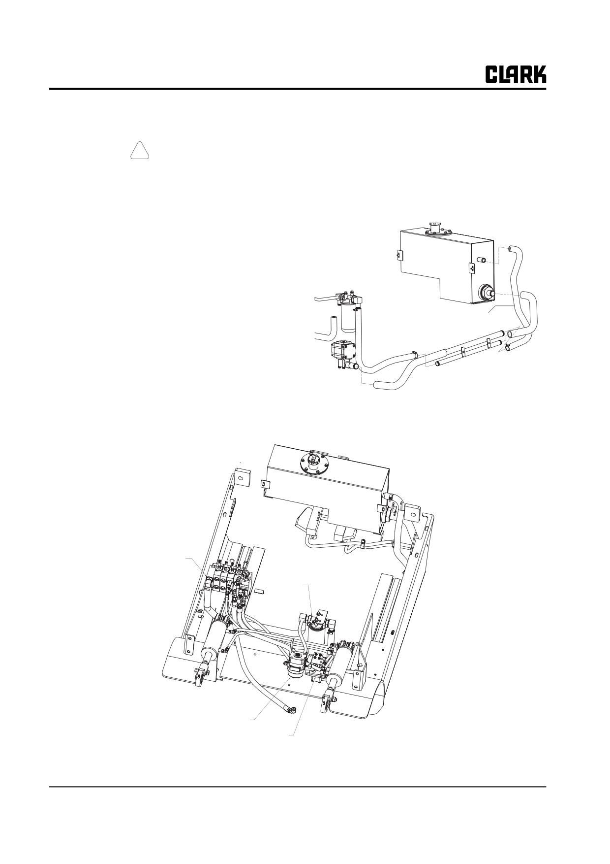
Group 29, Hydraulic Sump, Filters, and Pump
Main Hydraulic Pump Removal
NOTE
Capacity of hydraulic sump is 24 L (6.3 gal).
! CAUTION
1. Place a drip pan under the hydraulic pump for oil that
SAFE PARKING. Before working on truck:
will drain from the pump and hoses when they are
disconnected.
1. Park truck on a hard, level and solid sur-
face, such as a concrete floor with no
2. Disconnect suction line from pump and plug the line.
gaps or breaks.
2. Put upright in vertical position and fully
lower the forks or attachment.
3. Put ail controls in neutral. Turn key
switch OFF and remove key.
4. Disconnect the battery.
5. Apply the park brake and block the
Pump Suction Line
wheels.
The main hydraulic pump is located beneath the flow
plate. The pump can be removed from the truck without
removing the pump and motor assembly.
Serviceable items are the pump, motor and the suction
line filter. Other components such as hoses, fittings and
clamps are non-serviceable and should be replaced if
faulty.
Control Valve
Filter
Steering Gear
Pump
29-3-2 • Main Hydraulic Removal and Installation
SM 765, Sep ’06
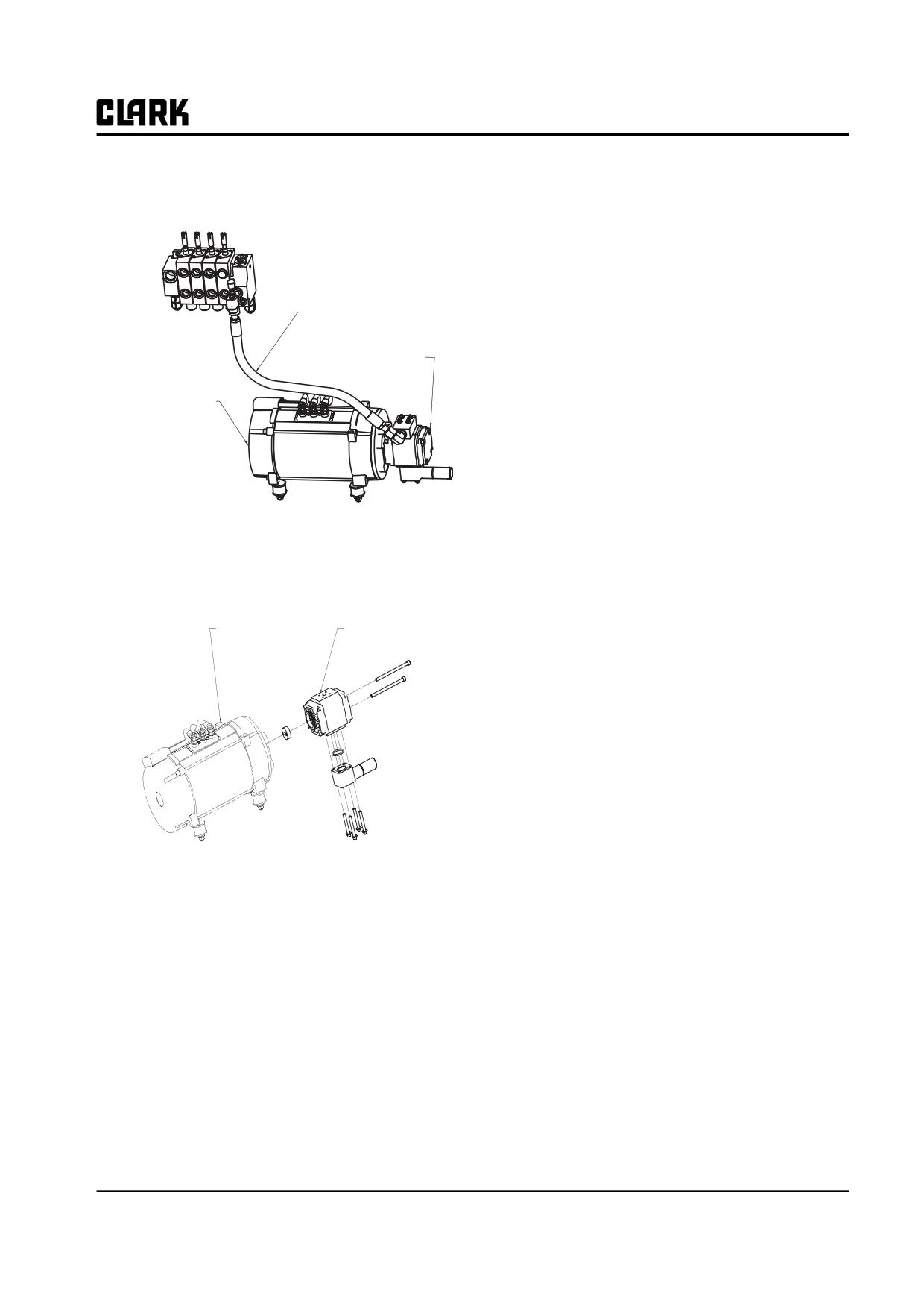
Group 29, Hydraulic Sump, Filters, and Pump
3. Disconnect the pressure line from the pump. Cap the
4. Connect pump outlet hose and tighten. Use two
hose and set aside.
wrenches to tighten hose fittings to prevent twisting
of lines.
NOTE
Always clean or replace hydraulic sump suc-
tion screen fitting when installing new or
Pressure Line
rebuilt pump. See Section 1, Main Hydraulic
Filters and Fluid Maintenance.
Hydraulic
5. Refill sump as necessary using Clark Specification
Pump
MS-68 hydraulic fluid. See Section 1 for description
Hydraulic Motor
of sump tank fill levels.
6. Reinstall hose and cable support bracket.
7. Check operation of hydraulic system. See Section 1,
Main Hydraulic Filters and Fluid Maintenance.
8. Check fluid level of sump again. Add fluid as neces-
sary.
4. Remove the pump mounting fasteners.The ground
strap will come off with the fasteners.
Routine Maintenance
• No maintenance is necessary other than periodic
checks for tightness of the mounting bolts and port
Hydraulic Motor
Hydraulic
fittings plus visual examination for oil leaks. The
Pump
unit should be kept externally clean.
• The unit must be operated on clean hydraulic fluid.
Directions for filter service in this Group must be
adhered to. A fluid cleanliness level of IS04406 17/
14 or better is recommended to give maximum life.
Main Hydraulic Pump Installation
IMPORTANT
Keep all components clean during installa-
tion.
1. Be sure new or serviced pump is well lubricated
before installation.
2. Install pump onto motor. Install and tighten cap-
screws.
3. Slide suction hose and clamp into place and tighten.
SM 765, Sep ’06
Main Hydraulic Removal and Installation • 29-3-3
NOTE :
Group 29, Hydraulic Sump, Filters, and Pump
SM 765, Sep ’06
GROUP 30
GROUP 30
HYDRAULIC CONTROL VALVE/LIFT CIRCUIT
Hydraulic Control Valve/Lift Circuit
Specifications and Description
Section 1
Hydraulic System Schematic
Section 2
Hydraulic System Troubleshooting
Section 3
Hydraulic System Pressure Checks
and Adjustments
Section 4
Hydraulic Control Valve Removal
and Replacement
Section 5
IMPORTANT
Other hydraulic-related components and circuits are
described and illustrated in Group 25, “Steering Column
and Gear”, Group 26 “Steer Axle”, Group 29, “Hydraulic
Sump, Filters and Pump”, Group 32, “Tilt Cylinders”, and
Group 34, “Uprights”. Refer to these other groups for
hydraulic components not covered in this group.
SM 765, Sep ’06
Group 30, HYDRAULIC CONTROL VALVE/LIFT CIRCUIT
NOTE :
Group 30, HYDRAULIC CONTROL VALVE/LIFT CIRCUIT
SM 765, Sep ’06
Group 30, Hydraulic Control Valve/Lift Circuit
Section 1
Hydraulic Control Valve/Lift Circuit
Specifications and Description
Specifications
Hydraulic Fluid Type: Clark specification MS-68 (Clark
Service Intervals
part #1802155 and #1800236)
Hydraulic System Relief Pressure Check: Every year or
Main Relief Valve Setting: 20.6 to 21.1 MPa (2988 to
every 2000 hours of operation.
3060 psi) at rated flow.
Auxiliary Relief Valve Setting: 13.7 to 14.2 kPa (1987 to
2060 psi) at rated flow.
Rated Flow: 76 L/min (20 gpm).
Maximum Pressure Drop at Rated Flow:
Inlet to outlet: 689 kPa (100 psi).
Lift spool (spool #l):
- Inlet to cylinder port: 689 kPa (100 psi)
- Cylinder port to outlet: 550 kPa (80 psi).
Tilt spool (spool #2):
- Inlet to cylinder port: 689 kPa (100 psi)
- Cylinder port to outlet: 550 kPa (80 psi).
Auxiliary spools (spools #3 and #4):
- Inlet to cylinder port: 345 kPa (50 psi)
- Cylinder port to outlet: 207 kPa (30 psi).
SM 765, Nov ’06
Hydraulic Control Valve/Lift Circuit Specifications and Description • 30-1-1
Group 30, Hydraulic Control Valve/Lift Circuit
moved. Excess oil flow is returned to the sump. A check
Description
valve prevents reverse flow.
The following description focuses primarily on hydraulic
When all the control valve spools are in neutral, the micro
circuitry controlled by the main hydraulic control valve,
switch turns the pump motor OFF and not fluid flows.
that is, the lift/tilt/aux circuit. Various other hydraulic sys-
When a spool is partially shifted and the associated cylin-
tems come into play, however, and are mentioned. The
der or other actuator has not reached its end-of-travel,
entire hydraulic system is depicted in the schematics in
some of the fluid flows to the cylinder (actuator) and the rest
Section 2 (next page).
flows to the sump line. In both cases, the pressure in the system
Descriptions of the braking and steering circuits are given
should be less than the amount required to open the relief valves.
in Groups 23 and 25.
The main relief valve vents flow to the sump when one of
The main hydraulic pump (described in Group 29) is
the following conditions is present:
driven by the pump motor and draws fluid from the sump
• The operator continues to hold the lift control in
through a particle-blocking suction screen.
the lift position after the lift mechanism reaches its
The main hydraulic control valve features an open-center,
endof-travel.
parallel-circuit type modular design. It has the main (lift/
• Too heavy a load is being lifted.
tilt) pressure relief valve (steering pressure relief valve
• The operator continues to hold the tilt control in
located in the steering control assembly (Orbitrol)), a sec-
the tilt position after the tilt mechanism has
ondary pressure relief valve for optional auxiliary compo-
reached its end-of-travel (This is called “tilt
nents, a lift spool, a tilt spool with an integral
bypass.“)
counterbalance valve, optional auxiliary spools, and
• Auxiliary relief fails to operate.
adjustable pressure-compensated flow controls. All spools
are low-leakage design.
The auxiliary relief valve vents flow to the sump when the
operator continues to hold the attachment control in the
The main hydraulic valve has from two to four valve sec-
operated position after the attachment reaches its end-of-
tions. Each section performs a separate function; standard
travel.
two spool assemblies have a inlet/lift section (with fluid
inlet port), a tilt section, and an outlet section. A third and
Main and auxiliary relief pressure settings can be checked
fourth section may be added to control auxiliary compo-
through a gauge port on the main valve.
nents.
A tilt-lock valve built into the main control valve assem-
When lift attachments are used, an auxiliary section may
bly locks the upright into its current tilt position when the
be added to the outer (RH) side of the standard (lift/tilt
truck is turned off. A load lowering flow valve mounted
only) main valve. The optional auxiliary sections also
on the upright limits the speed at which the operator can
have an adjustable relief valve and can be assembled with
lower a load, decreasing the speed for heavier loads. A
optional flow control levels.
velocity fuse built into one of the lift cylinder ports pre-
vents the upright from falling rapidly should a hydraulic
The valve spools are arranged in standard sequence (from
line rupture or be disconnected.
the operator’s position) to first provide lift control, then
tilt, and finally auxiliary control. The control levers are
spring-loaded (by the valve spool centering springs) to
return them to neutral when released. Oil flow is con-
trolled by the amount or distance the control handles are
NOTE
Hydraulic plumbing arrangement is illustrated in Group 29.
30-1-2 • Hydraulic Control Valve/Lift Circuit Specifications and Description
SM 765, Nov ’06
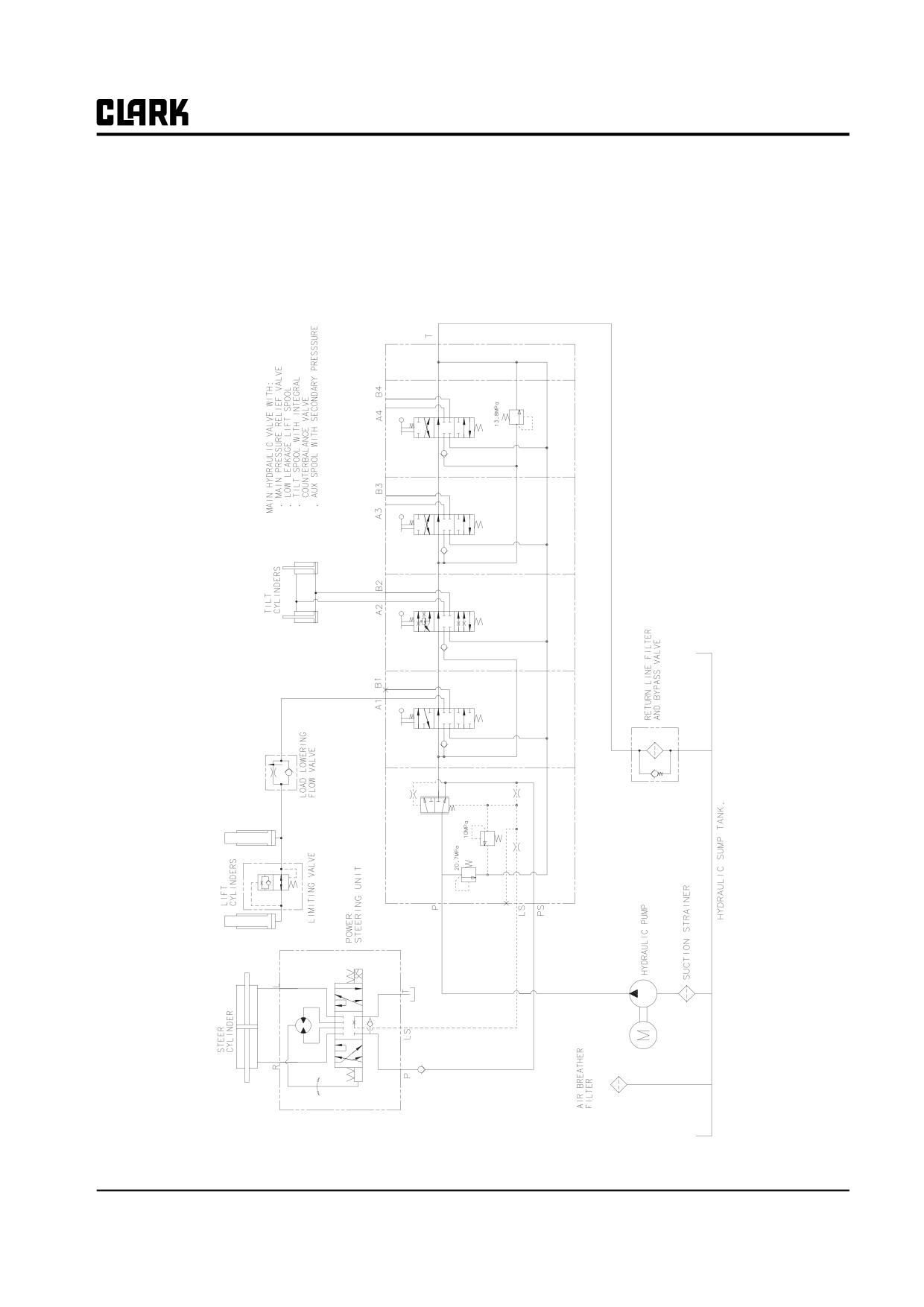
Group 30, Hydraulic Control Valve/Lift Circuit
Section 2
Hydraulic Schematic
Hydraulic Circuit(For Normal Valve)
SM 765, Nov ’06
Hydraulic Schematic • 30-2-1
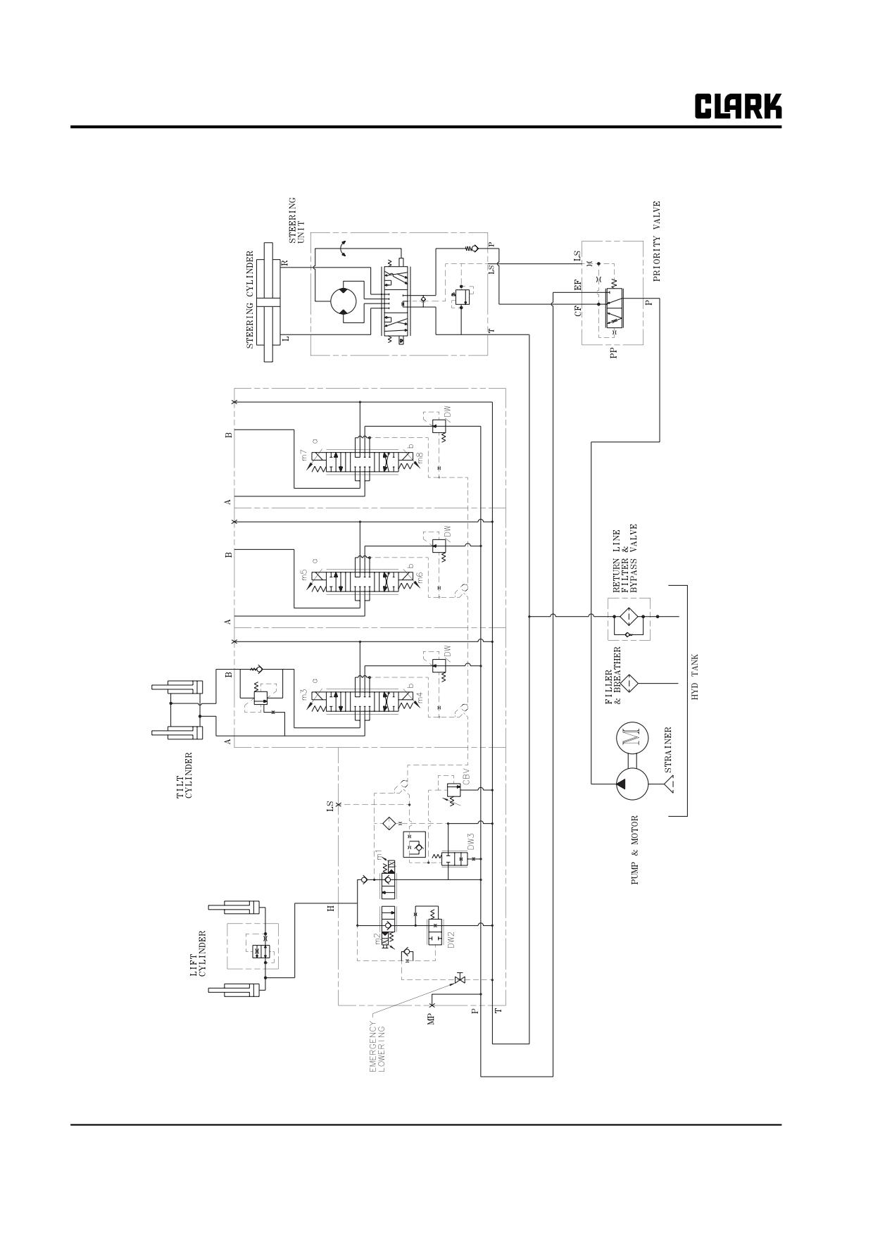
Group 30, Hydraulic Control Valve/Lift Circuit
Hydraulic Circuit(For ELH Valve)
30-2-2 • Hydraulic Schematic
SM 765, Nov ’06
Group 30, Hydraulic Control Valve/Lift Circuit
Section 3
Hydraulic System Troubleshooting
The following is a list of problems and solutions relating
• Cavitating pump; check hydraulic plumbing for
to the main hydraulic control valve and associated compo-
airtight hoses and connections.
nents. For other hydraulic system troubleshooting, refer to
• Pump driveshaft misaligned; check mounting and
Groups 29 and 34.
alignment.
No lift, tilt, or auxiliary function
• Axial loading on drive shaft; check shaft end clear-
ance and shaft alignment; check for worn key/
• Hydraulic fluid very low; check and fill to correct
spline.
level.
• Relief valve in bypass; check relief setting.
• Hose or fittings broken; replace component.
• Defective main lift valve; check other Trouble-
Load cannot be lifted to maximum height
shooting items for possible cause, then consider
rebuilding or replacing main lift valve.
• Hydraulic fluid low: check and fill to correct level.
• Hydraulic pump defective: check other Trouble-
• Hydraulic pump defective; check other Trouble-
shooting items for possible cause, then consider
shooting items for possible cause, then consider
rebuilding or replacing pump.
rebuilding or replacing pump.
No motion, slow or jerky action of
Oil leaks at top of lift (secondary) cylinder(s)
hydraulic system
• Plugged vent line; check and clear line.
• Spool not moved to full stroke; check travel and
• Worn or damaged piston seal: rebuild cylinder.
linkage adjustment.
• Scored cylinder wall; replace cylinder.
• Relief valve not properly set, stuck in place, and/or
See Group
34, “Cylinder Removal, Overhaul, and
worn; check and clean valve, replace if necessary.
Replacement.”
• Dirt or foreign particles lodged between relief
valve control poppet and seat: check valve and
Oil leak at tilt or auxiliary function cylinder
clean.
• Worn or damaged seal; rebuild cylinder.
• Valve body cracked inside; check and replace
entire valve.
• Scored piston rod; repair or replace rod.
See Group
34, “Cylinder Removal, Overhaul, and
Foaming hydraulic fluid
Replacement.”
• Low oil level; check and fill to correct level.
Load will not hold
• Wrong fluid; drain and refill with correct oil.
• Oil too heavy; change to correct viscosity.
• .Oil bypassing between lift spool and valve body; over-
• Pump inlet line restriction or line kinked; clean line
haul valve and spool.
and suction screen or repair kinked hose.
• Spool not centered; see spool remedies for correct-
• Hydraulic pump cavitating (pumping air with
ing problems when spools do not return to neutral.
fluid); check hydraulic plumbing for airtight hoses
• Oil bypassing piston in cylinder; repair or replace
and connections.
cylinder.
Overheated hydraulic fluid
Oil leaks at either end of main hydraulic
• Thin fluid; drain and fill with correct fluid.
valve spool
• Fluid contaminated; drain sump, clean suction
• Defective O-ring seals; rebuild valve.
screen, replace filter, and refill.
SM 765, Sep ’06
Hydraulic System Troubleshooting • 30-3-1
Group 30, Hydraulic Control Valve/Lift Circuit
Spring-centered spools do not return to
No relief valve action (high pressure)
neutral
• Small particles of dirt in relief valve subassembly;
check, clean, and/or replace relief valve, clean
• Broken springs; rebuild valve.
hole.
• Entrapped foreign particles; check and clean sys-
• Relief valve subassembly installed backwards;
tem and valve.
reinstall correctly.
• Bent spool; replace with new valve section.
• Misalignment or binding of linkage; check and
Load drops when spool is moved from
align/adjust linkage.
neutral to lift position
• Dirt or foreign particles lodged between check
valve ball and seat; check and clean.
• Sticking or scored check valve; clean if sticking,
replace if scored, replace poppet.
30-3-2 • Hydraulic System Troubleshooting
SM 765, Nov ’06
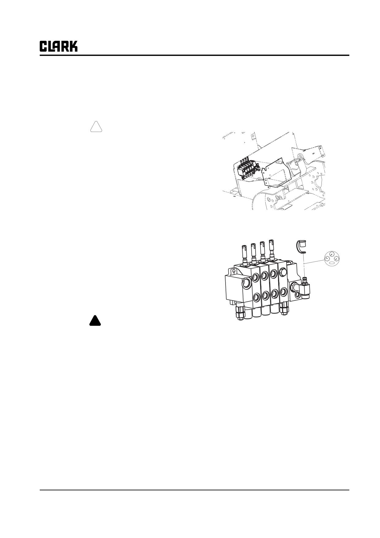
Group 30, Hydraulic Control Valve/Lift Circuit
Section 4
Hydraulic System Pressure Checks and Adjustments
! CAUTION
SAFE PARKING. Before working on truck:
1. Park truck on a hard, level, and solid
surface, such as a concrete floor with no
gaps or breaks.
2. Put upright in vertical position and fully
lower the forks or attachment.
3. Put all controls in neutral. Turn key
switch OFF and remove key.
4. Apply the parking brake and block the
wheels.
2.
Remove the cap from the gauge port on the valve and
connect pressure gauge to the fitting.
Relief Pressure Checks
Following is the procedure for checking main hydraulic
valve lift pressure and auxiliary relief pressure (if the
truck is equipped with an auxiliary component).
Hydraulic system relief pressure setting may be checked
using a Mica Quadrigage (Clark Part No. 923770) or with
a conventional pressure gauge with suitable pressure
range calibration. To cover all models of the truck, a
gauge with capacity range of 0 to 34,475 kPa minimum (0
to 5000 psi) is recommended.
! WARNING
HYDRAULIC FLUID SAFETY. Keep all
NOTE
hydraulic ports and components clean. Wipe
Use quick-disconnect adapter fitting, Clark
the area on the pump around the diagnostic
Part #913125.
check port completely clean to prevent any
3.
Check main relief pressure: Turn key switch on,
contamination from entering the hydraulic
system.
move the lift control lever to full back lift relief posi-
tion. Hold lift control in relief position until pressure
When checking the hydraulic system, do not
reading is obtained, and then release. Gauge should
use your hands to check for leakage. Use a
piece of cardboard or paper to search for
read 20,600 to 21,100 kPa (3988 to 3060 psi).
leaks. Escaping fluid under pressure can pen-
IMPORTANT
etrate the skin causing serious injury. Relieve
Do not operate system in relief any longer
pressure before disconnecting hydraulic or
than required to read the pressure gauge.
other lines. Tighten all connections before
applying pressure. Keep hands and body
4.
Check auxiliary relief pressure: (Truck must have
away from pinholes and nozzles which eject
auxiliary component and auxiliary section added to
fluids under high pressure.
main hydraulic valve.) Move the auxiliary control
1. Remove the covers enclosing the main hydraulic
lever to full back or forward relief position. Hold
auxiliary control in relief position until pressure
valve to access the hydraulic system pressure diag-
reading is obtained, and then release. Gauge should
nostic check port.
read 13,700 to 14,200 kPa (1987 to 2060 psi).
SM 765, Nov '06
Hydraulic System Pressure Checks and Adjustments • 30-4-1
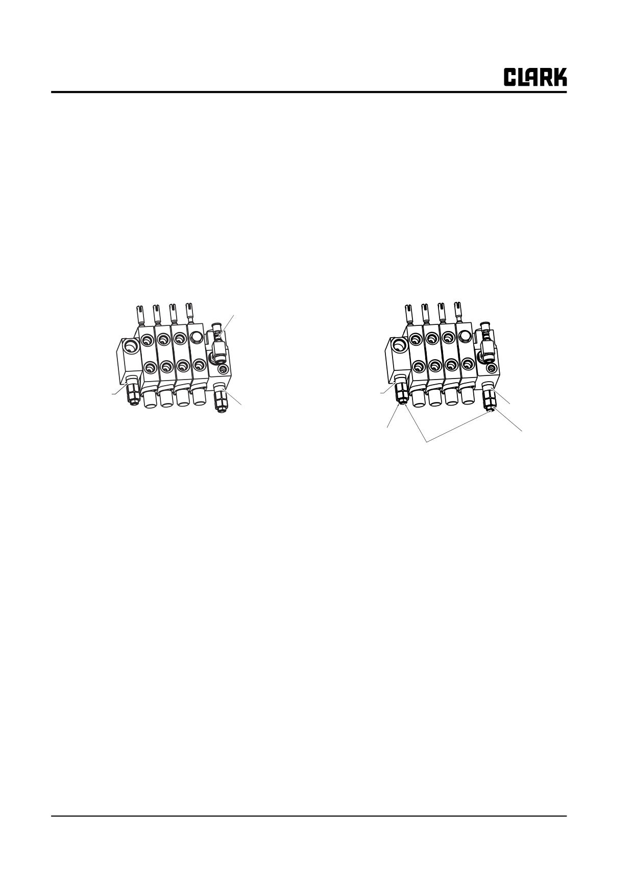
Group 30, Hydraulic Control Valve/Lift Circuit
Main Pressure Relief Adjustment
Auxiliary Pressure Relief Adjustment
IMPORTANT
IMPORTANT
Main pressure relief setting is set at the fac-
The auxiliary relief setting only applies to a
tory. If the relief pressure does not measure
hydraulic valve that has auxiliary sections
within the setting range, main pressure relief
added.
setting is adjusted.
To adjust the hydraulic system auxiliary pressure relief
To adjust the hydraulic system main pressure relief valve:
valve:
1. Loosen the jam nut on the main relief valve adjust-
1. Loosen the jam nut on the auxiliary relief valve
ment screw.
adjustment screw.
Pressure
check port
Secondary
Secondary
relief valve
relief valve
Main
Main
relief valve
relief valve
Jam nut
Jam nut
Adjustement screw
2. Turn the adjustment screw to set the main pressure
2. Turn the adjustment screw to set the auxiliary pres-
relief setting to the normal range.
sure relief setting to the normal range.
3. Reset the jam nut on the main relief valve adjustment
3. Reset the jam nut on the auxiliary relief valve adjust-
screw.
ment screw.
30-4-2 • Hydraulic System Pressure Checks and Adjustments
SM 765, Nov ’06
Group 30, Hydraulic Control Valve/Lift Circuit
GEX 30
Flowrate per RPM
Lift
Tilt in
GEX 20/25
Flowrate
Speed
velocity
RPM
Hz
Remark
Lift
Tilt in
mm/
mm/
deg/
Flowrate
lpm
gpm
Speed
velocity
sec
sec
sec
RPM
Hz
Remark
mm/
mm/
deg/
500
15
8.0
2.1
68
19.29
3.10
lpm
gpm
sec
sec
sec
600
18
9.8
2.6
83
23.63
3.80
500
15
9.7
2.6
82
23.39
3.76
700
21
11.6
3.1
99
27.97
4.50
600
18
11.8
3.1
100
28.45
4.57
800
25
13.4
3.6
114
32.31
5.19
700
21
14.0
3.7
118
33.76
5.43
900
28
15.2
4.0
129
36.65
5.89
800
25
16.1
4.3
137
38.82
6.24
1000
31
17.1
4.5
145
41.24
6.63
900
28
18.2
4.8
155
43.89
7.05
1100
35
18.9
5.0
160
45.58
7.32
1000
31
20.4
5.4
173
49.19
7.91
1200
38
20.7
5.5
175
49.92
8.02
1100
35
22.5
5.9
191
54.26
8.72
1300
41
22.5
5.9
191
54.26
8.72
1200
38
24.7
6.5
209
59.56
9.57
1400
45
24.3
6.4
206
58.60
9.42
1300
41
26.8
7.1
227
64.63
10.39
1500
48
26.1
6.9
221
62.94
10.12
1400
45
28.9
7.6
245
69.69
11.20
1600
51
27.9
7.4
236
67.28
10.81
1500
48
31.1
8.2
263
75.00
12.05
1700
55
29.7
7.8
252
71.62
11.51
1600
51
33.2
8.8
282
80.06
12.87
1800
58
31.5
8.3
267
75.96
12.21
1700
55
35.3
9.3
300
85.12
13.68
1900
61
33.3
8.8
282
80.30
12.91
1800
58
37.5
9.9
318
90.43
14.53
2000
65
35.1
9.3
298
84.64
13.60
1900
61
39.6
10.5
336
2100
68
36.9
9.8
313
88.98
14.30
2000
65
41.8
11.0
354
2200
71
38.7
10.2
328
2100
68
43.9
11.6
372
2300
75
40.5
10.7
344
2200
71
46.0
12.2
390
2400
78
42.3
11.2
359
2300
75
48.2
12.7
408
2500
81
44.1
11.7
374
2400
78
50.3
13.3
427
2600
85
45.9
12.1
389
2500
81
52.4
13.9
445
2700
88
47.7
12.6
405
2600
85
54.6
14.4
463
2800
91
49.5
13.1
420
2700
88
56.7
15.0
481
2900
95
47.7
13.6
435
2800
91
58.9
15.5
499
3000
98
53.2
14.0
451
2900
95
61.0
16.1
517
3100
101
55.0
14.5
466
3000
98
63.1
16.7
535
3200
105
56.8
15.0
481
3100
101
65.3
17.2
553
3300
108
58.6
15.5
497
3200
105
67.4
17.8
572
3400
111
60.4
15.9
512
3300
108
69.5
18.4
590
3500
115
62.2
16.4
527
3400
111
71.7
18.9
608
3500
115
73.8
19.5
626
* The above are only theoretical value.
• Displacement of pump : 19 cc/rev
* The above are only theoretical value.
• Volumetric efficiency of pump : 0.95
• Displacement of pump : 22.5 cc/rev
• Volumetric efficiency of pump : 0.95
SM 765, Nov ’06
Hydraulic System Pressure Checks and Adjustments • 30-4-3
NOTE :
Group 30, Hydraulic Control Valve/Lift Circuit
SM 765, Nov ’06
Group 30, Hydraulic Control Valve/Lift Circuit
Section 5
Hydraulic Control Valve Removal and Replacement
Hydraulic Control Valve Removal
2
Preparation for Valve Removal
2
Control Valve Linkage Disassembly
2
Valve Removal
2
Hydraulic Control Valve Replacement
3
Valve Replacement
3
Control Valve Linkage Reassembly
3
Operational Checks
4
! CAUTION
SAFE PARKING. Before working on truck:
1. Park truck on a hard, level, and solid surface, such as a
concrete floor with no gaps or breaks.
2. Put upright in vertical position and fully lower the forks or
attachment.
3. Put all controls in neutral. Turn key switch OFF and
remove key.
4. Apply the parking brake and block the wheels.
SM 765, Sep ’06
Hydraulic Control Valve Removal and Replacement • 30-5-1
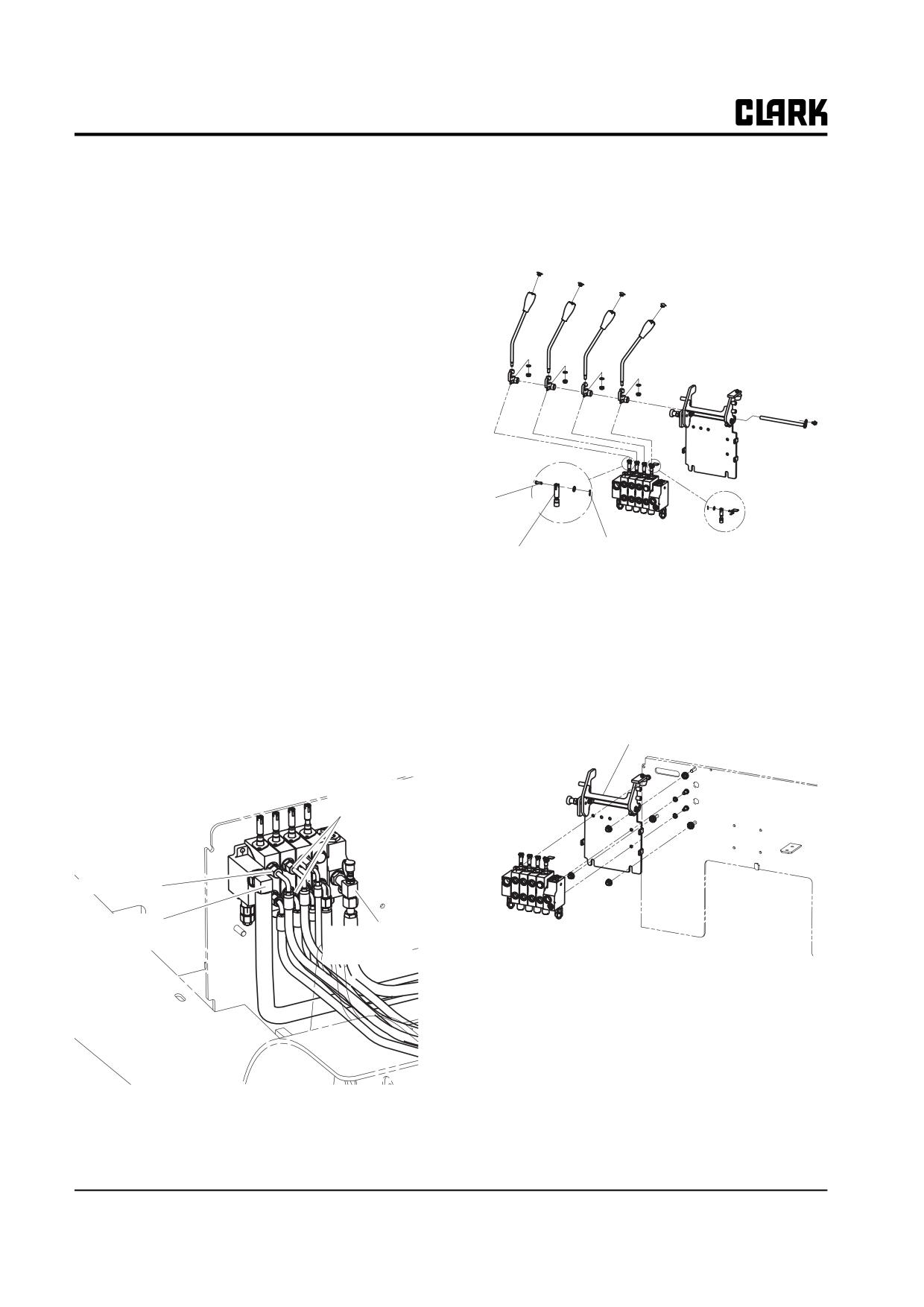
Group 30, Hydraulic Control Valve/Lift Circuit
Hydraulic Control Valve Removal
Control Valve Linkage Disassembly
IMPORTANT
Remove the cotter rings and clevis pins connecting the lift
Keep all hydraulic ports, components, and
and tilt (and auxiliary, as applicable) lever rods from the
fittings completely clean during valve
hydraulic valve spools.
removal and replacement to prevent any con-
tamination from entering the hydraulic sys-
tem.
Preparation for Valve Removal
1. Park truck in a safe position and fully lower the
upright.
2. Return all controls to neutral, apply the parking
brake, and turn key switch OFF.
3. Move all hydraulic control levers to all working posi-
tions and return them to neutral. Be sure there is no
Clevis Pin
hydraulic pressure applied to the system by attach-
ments.
Cotter Pin
Valve Spool
4. Remove floor plate.
5. Remove the right cowl cover from under the dash in
the operator’s compartment. See removal and
Valve Removal
replacement procedures in Group 38.
1. Remove the three hex capscrews mounting the
6. Air clean the hydraulic valve and fittings.
hydraulic valve to the hydraulic valve mounting
bracket .
7. Place a drain pan under the truck and loosen and
remove all hydraulic lines from the valve. Plug the
valve ports. Mark or tag each line as removed to
Hydraulic Valve mounting
Bracket
assure correct position of line at assembly.
Tilt Cylinder
Lines
To upringt
Feed Line
from Pump
Return Line
to Sump
2. Remove valve assembly from valve mounting
bracket. See Section 6 for valve overhaul instruc-
tions.
NOTE
Be sure to clean up any oil spills and dry the
floor to prevent accidents.
8. Cap ends of lines to keep them clean. Tie ends of
lines to truck to prevent loose ends dropping and
leaking oil onto floor
30-5-2 • Hydraulic Control Valve Removal and Replacement
SM 765, Sep ’06