Clark GEX20-30 (RATED CAPACITY : 2000~3000kg). SERVICE MANUAL (2006) - page 4
Group 30, Hydraulic Control Valve/Lift Circuit
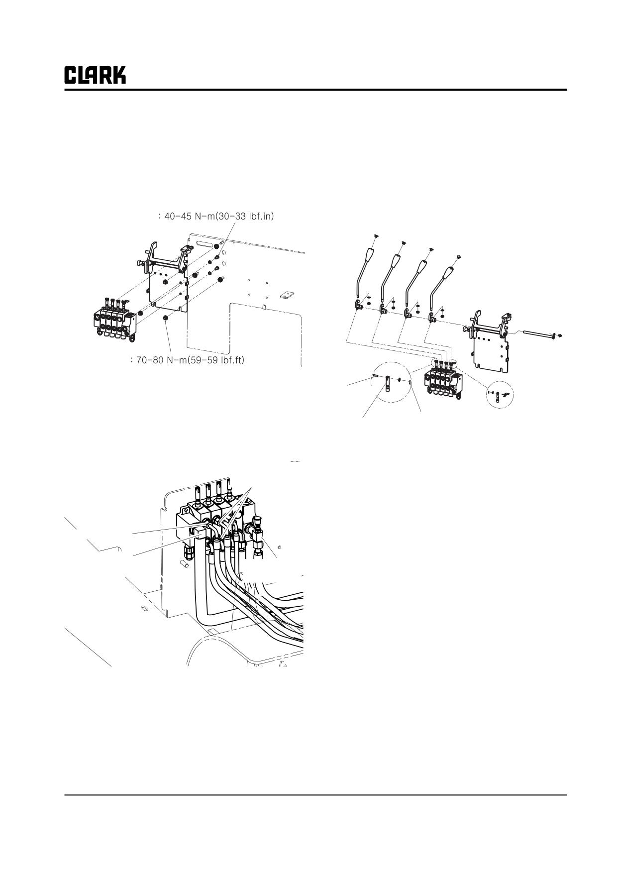
Hydraulic Control Valve Replacement
Control Valve Linkage Reassembly
1. Insert the clevis pins through the rod-end clevises
Valve Replacement
and valve spools of the lift and tilt spools (and auxil-
iary-lever rods and spools where applicable) and
1. Install the main valve on the valve mounting bracket.
secure with the cotter rings. Rotation of the valve
2. Install the valve mounting bracket on the frame.
spools is required to allow insertion of the clevis
pins. Rotate spools back so all pins are in line.
Torque to
Torque to
3. Install the hydraulic lines on the proper ports. Make
Clevis Pin
sure all lines are clean, arerouted correctly in the
truck, and are not kinked. Torque fittings according
Cotter Pin
to “Hydraulic Fitting Tightening Procedure” in
Valve Spool
Group 40.
NOTE
Tilt Cylinder
The illustration above and system specifica-
Lines
tion torques also apply for auxiliary hydrau-
lic functions, such as a side-shifter or rotator.
2. Set the interval of lever, then tighten the nuts under
To Upringt
the lever with torque of 40-50Nm(30-33ft.lb).
Feed Line
Return Line
from Pump
to Sump
SM 765, Sep ’06
Hydraulic Control Valve Removal and Replacement • 30-5-3
Group 30, Hydraulic Control Valve/Lift Circuit
Reinstall Valve
Operational Checks
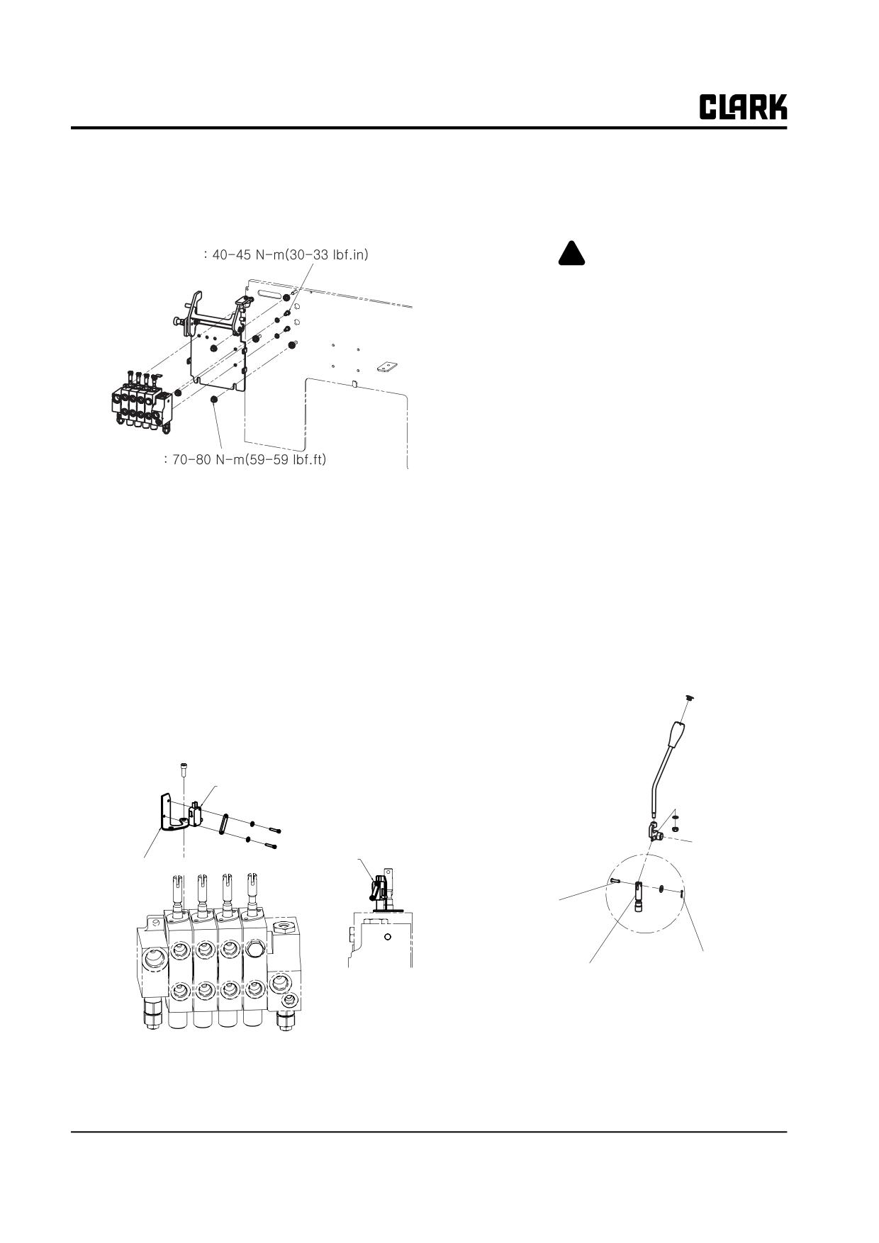
1. Reinstall valve and valve plumbing.
1. Operate the truck and hydraulic system. Check the
system for leaks.
Torque to
!
WARNING
Do not use your hands to check for hydraulic
leakage. Use a piece of cardboard or paper to
search for leaks. Escaping fluid under pres-
sure can penetrate the skin causing serious
injury. Relieve pressure before disconnecting
hydraulic or other lines. Tighten all connec-
tions before applying pressure. Keep hands
and body away from pinholes and nozzles
which eject fluids under high pressure.
If any fluid is injected into the skin, it must
be surgically removed within a few hours by
Torque to
a doctor familiar with this type injury or
gangrene may result.
2. Check the operation of the valve and hydraulic sys-
Lift and Tilt Pump Switches
tem by moving the valve control levers to the various
positions. The levers must operate smoothly with no
binding. When released from any working position,
Adjustment
the levers must return sharply to their neutral posi-
tions.
1. Turn key switch to the OFF position.
If valve spools do not moved or return to correct
2. Loosen switch mounting screws.
position for full function of lift, tilt, or auxiliary cyl-
inders:
3. Adjust switch to activate after 2 mm (0.08 in.) of
spool travel from neutral.
a. When inserting the pin to the lever, check it is
smoothly inserted.
4. Tighten mounting screws.
Micro Switch
Switch shown
Switch Mounting
mounted
Bracket
Clevis Pin
Cotter Pin
Valve Spool
3. Refer to Section 4, “Hydraulic System Pressure-
Check” if valve was disassembled or overhauled.
30-5-4 • Hydraulic Control Valve Removal and Replacement
SM 765, Sep ’06
GROUP 32
GROUP 32
TILT CYLINDERS
Tilt Cylinder Specifications and Description
Section 1
Checks and Adjustments
Section 2
Tilt Cylinder Removal and Installation
Section 3
Tilt Cylinder Overhaul
Section 4
IMPORTANT
Other hydraulic-related components and curcuits are
described and Illustrated in Group 25, “Steering Column
and Gear”, Group 26 “Steer Axle”, Group 29, “Hydraulic
Sump, Filters, and Pump”, Group 30, Hydraulic Control
Valve/Lift Circuit.” and Group 31, “Uprights.” Refer to these
other groups for hydraulic components not covered in this
group.
SM 765, Nov ’06
Group 32, tilt cylinders
NOTE :
Group 32, tilt cylinders
SM 765, Nov ’06
Group 32, Tilt Cylinders
Section 1
Tilt Cylinder Specifications and Description
Specifications
Service Intervals
See Group 30 for hydraulic system specifications.
Tilt Cylinder Drift Test: Every 50-250 hours or each PM.
Tilt Cylinder Type: Double-acting
Tilt Cylinder Check and Adjustment: Every 50-250 hours
or each PM.
Maximum Operating Pressure: 21,000 kPa (3,000 psi)
Tilt Cylinder Rod Seal Condition Check: Every 50-250
Tilt Ranges*:
hours or each PM.
MAST
BACK
FORWARD
MFH mm(in)
Tilt Cylinder Mounting Check and Tightening: Every 50-
TYPE
"B"( ˚ )
"F"( ˚ )
250 hours or each PM.
GEX
Tilt Cylinder Rod-End Check and Tightening: Every 50-
STD
~2015(83)
8
8
250 hours or each PM.
STD
2680(105.5)~3860(152)
8
8
STD
4165(164)~4620(182)
5
6
Tilt Cylinder Rod-End Lubrication: Every 50-250 hours
STD
5170(203.5)
5
3
or each PM.
TSU
3860(152)~4800(189)
5
6
TSU
5050(199)~6100(240)
5
3
Description
TSU
6370(251)~
3
3
The tilt cylinders provide backward and forward tilt of the
QUAD
ALL
3
3
upright. The forward and back tilt angles are governed by
the cylinder stroke and by use of spacers and different
Abbreviations: Std = Standard, high-visibility upright;
length rod ends. The tilt cylinders are pin-mounted to the
TSU = Triple-stage upright; MFH = maximum fork
truck frame and upright using yokes, clevises, and pins.
height; B = back tilt; F = forward tilt. See truck data plate
Pins are held in place by a lock plate and fastener to pre-
for upright MFH.
vent the pins from working their way out.
The tilt cylinders are serviced by removing them from the
Fastener Torques
truck and disassembling them for complete overhaul,
including installation of new seals and or other cylinder
Rod-End Yoke Bolts: 166-193 N.m (122-142 ft-lb)
components.
Rod-End Pin Lock Plate Fasteners: 40-45 N⋅m (30-33 ft-
The tilt lock valve is integrated into the tilt section of the
lb).
main hydraulic control valve. The tilt lock valve prevents
Base Mount Pin Lock Plate Fasteners: 40-45 N⋅m (30-33
the upright from tilting forward when the truck is not run-
ft-lb).
ning. The tilt lock valve is not serviceable and must be
replaced as a valve section if defective.
SM 765, Nov ’06
Tilt Cylinder Specifications and Description • 32-1-1
NOTE :
Group 32, Tilt Cylinders
SM 765, Nov ’06
Group 32, Tilt Cylinders
Section 2
Tilt Cylinder Checks and Adjustments
Tilt Cylinder Drift Test
1
Drift Causes and Remedies
2
Tilt Cylinder Racking Check
2
Forward Adjustment
2
Backward Adjustment
3
Tilt Flow Control Adjustments
3
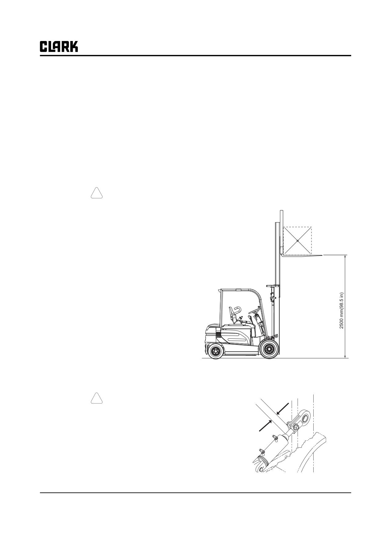
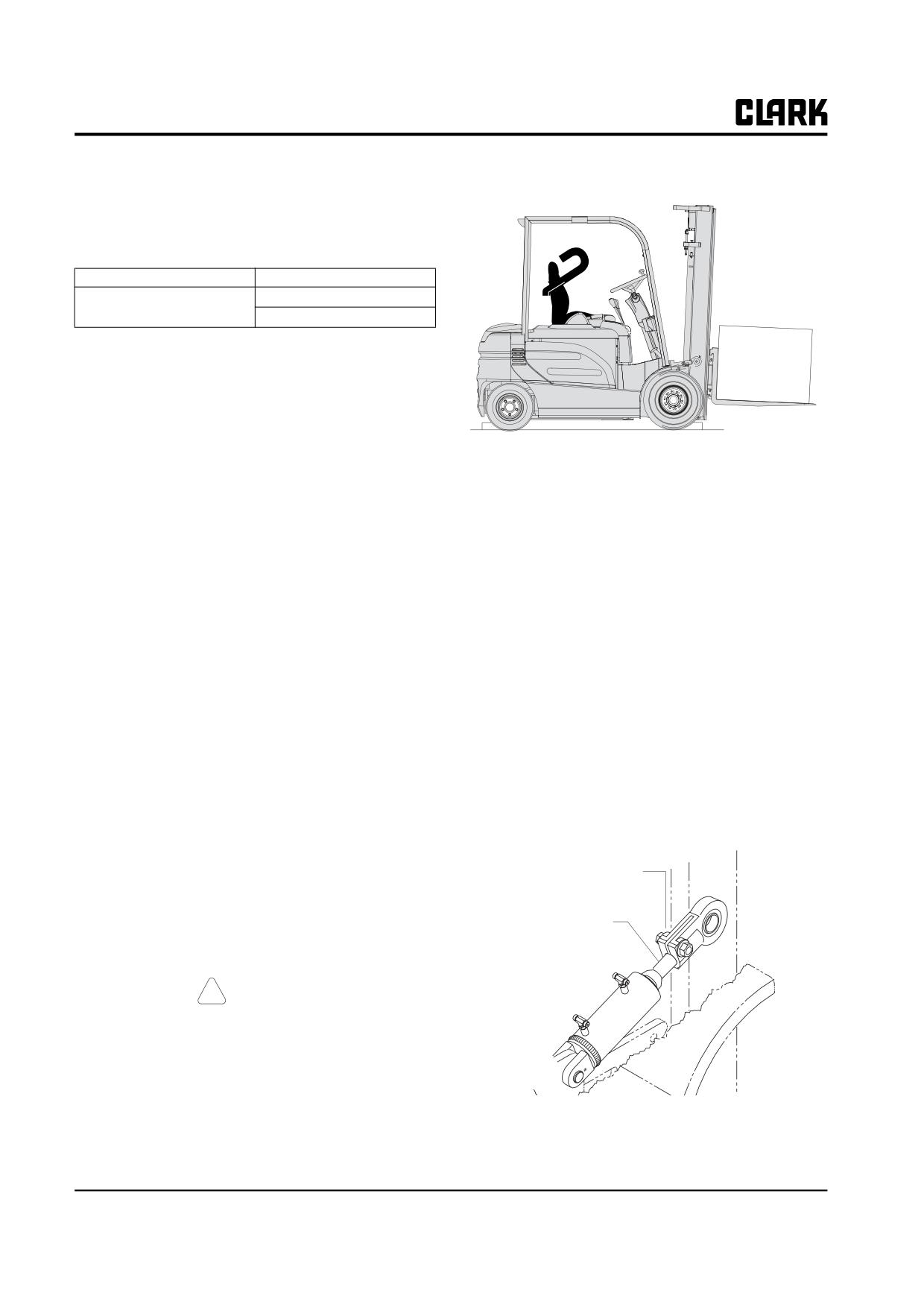
3. Raise the capacity load 2500 mm (98.5 in) off the
! CAUTION
ground and tilt the upright vertical. Shut off the truck.
SAFE PARKING. Before working on truck:
1. Park truck on a hard, level, and solid
surface, such as a concrete floor with no
gaps or breaks.
2. Put upright in vertical position and fully
lower the forks or attachment.
3. Put all controls in neutral. Turn key
switch OFF and remove key.
4. Apply the parking brake and block the
wheels.
Tilt Cylinder Drift Check
To check tilt cylinder drift, a rated capacity load is placed
on the forks, lifted up and held to determine if the tilt cyl-
inder rods moves (drifts) in a specified length of time.
It is recommended that a test load, made up of a full-
capacity load equally distributed on a 1220 x 1220 mm
(48 x 48 in) pallet, be used. The material used to make up
the test load must be stacked to provide load stability and
must not extend beyond the pallet. It must be secured on
the pallet. Refer to the truck data plate for capacity rating.
4. Measure and write down the distance between the
1. Adjust fork width as wide as possible to distribute
cylinder-spacer face and the rod-end yoke.
the load. Refer to truck nameplate for capacity rating.
Measure rod
! CAUTION
distance here
Test load must be stacked stably, not extend
beyond the pallet, and be secured on the pal-
let. Clamp the load on the load backrest or
fork bar to avoid sliping out from fork.
2. Drive the forks into the load pallet until the test load
and pallet rest against the load backrest. Apply the
parking brake and chock the wheels.
SM 765, Nov ’06
Tilt Cylinder Checks and Adjustments • 32-2-1
Group 32, Tilt Cylinders
5. Wait five minutes and measure and write down dis-
tance between rod end and spacer.
6. The measurement must not exceed the following
measures:
Temperature
Drift
0.5°, 3.9mm @ 1 min
50°C(122°F)
5°, 39 mm @ 10 min
Drift Causes and Remedies
Tilt cylinder drift indicates the following possible prob-
lems:
• Tilt cylinder hydraulic circuit hoses or fittings are
leaking. Check the circuit components and repair
as necessary.
Forward Adjustment
• Cylinder piston seals are worn, damaged, or defec-
tive allowing fluid past the piston and causing the
1. Slowly tilt upright fully forward to the end of the tilt
rod to drift. Consider rebuilding the cylinders if the
cylinder stroke.
other remedies in this list are not successful. See
2. As the cylinders approach the end of the stroke,
Section 3 for cylinder removal and replacement
watch both piston rods for equal movement and
and Section 4 for cylinder repair, if necessary.
upright for twisting. Note if upright “racks” (is
• The main hydraulic tilt valve is misadjusted, worn,
twisted at the end of its movement by unequal stroke
or defective. Fluid is leaking past the valve and
of tilt cylinders).
causing the tilt cylinders to drift. See Group 30 for
NOTE
hydraulic valve troubleshooting.
Correct the twisting effect by shortening the
cylinder that is the longest length. Forward
Tilt Cylinder Racking Check
twisting must be adjusted before backward
Upright racking occurs when tilt cylinder strokes are
twisting. If forward adjustment is not
unequal. Cylinders should be checked regularly during
needed, continue with backward adjustment.
operation to determine if cylinder strokes are the same. To
check for racking:
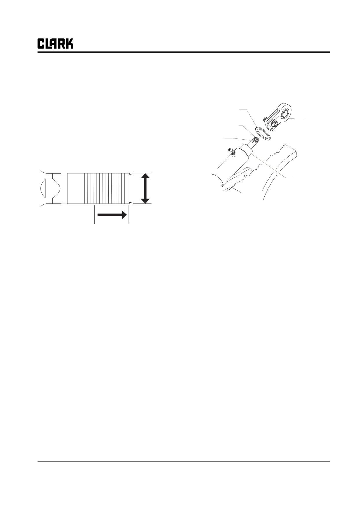
3. To adjust, loosen rod-end yoke capscrew on the tilt
cylinder that extends the farthest, and turn piston rod
• Make sure uuck is parked on level surface with
parking brake applied and wheels chocked.
into rod-end yoke to shorten.
• Check condition of the tilt cylinder, rod-end yoke,
Loosen
mounting pins, piston rod, rod wiper, cylinder
capscrew.
gland, etc., for excessive wear or damage. Make
repairs before making twisting adjustment.
Turn to adjust.
• Use a capacity load (see truck nameplate) centered
on the forks.
! CAUTION
Be sure to secure the load to the fork carriage
to keep it from falling off when tilted for-
ward.
Raise the upright only to the height that will
allow the fork tips to clear the floor when
Forward Adjustment: Pneumatic-tire truck rod-end yoke
tilted fully forward.
orientation shown.
32-2-2 • Tilt Cylinder Checks and Adjustments
SM 765, Nov ’06
Group 32, Tilt Cylinders
NOTE
4. Use rod shims to fill in the space between the rod-
Use wrench flat on rod under spacer (if
end yoke and spacer. Screw rod back into yoke the
installed). Move spacer for access.
same number of turns needed to remove.
4. Continue to turn rod into rod end until tilt cylinder
strokes are equal.
Rod Shim
Rod-End
IMPORTANT
Yoke
Cylinder Rod
The rod must he threaded onto the rod-end
yoke a distance at least as great as the diame-
Wrench Flat
ter of the rod plus 6.5 mm (0.25 in).
Add 6.5
Spacer
mm (.25
in) to
diameter
of rod.
5. Tighten capscrew of the rod-end yoke to 166-193
Thread rod into rod-
end yoke the rod
N⋅m (122-142 ft-lb), and repeat the racking test.
diameter plus 6.5 mm
6. Repeat steps l-5 for fine corrections if any racking
(0.25in).
remains evident.
7. When no racking occurs, retighten yoke capscrew to
5. Tighten capscrew of the rod-end yoke to 166- 193
166-193 N⋅m (122-142 ft-lb).
N.m (122-142 ft-lb), and repeat the racking test.
8. Check all tilt functions before returning the truck to
6. Repeat steps 1-5 for fine corrections if any racking
service.
remains evident.
7. When no racking occurs, retighten capscrew of the
rod-end yoke to 166-193 N⋅m (122-142 Et-lb).
8. Check all tilt functions before returning the truck to
service.
Backward Adjustment
Perform forward check and adjustment first. Then:
1. Slowly tilt upright fully backwards while watching
piston rods. They should both bottom out at the same
time. If they don’t, adjust backward tilt using the fol-
lowing steps.
2. Stop the upright when the first tilt cylinder bottoms
out against its rod spacer.
3. Go to the opposite cylinder and remove the capscrew
on the rod-end yoke and screw rod out of yoke.
Count the number of turns required to remove the rod
from the yoke.
SM 765, Nov ’06
Tilt Cylinder Checks and Adjustments • 32-2-3
NOTE :
Group 32, Tilt Cylinders
SM 765, Nov ’06
Group 32, Tilt Cylinders
Section 3
Tilt Cylinder Removal and Replacement
Tilt Cylinder Removal
2
Parts Inspection
3
Tilt Cylinder Replacement
3
SM 765, Nov ’06
Tilt Cylinder Removal and Replacement • 32-3-1
Group 32, Tilt Cylinders
! CAUTION
!
WARNING
SAFE PARKING. Before working on truck:
The upright assembly is heavy. Use only
hoists with enough capacity to lift the entire
1. Park truck on a hard, level,-and solid
assembly. Keep hands and feet away from the
surface, such as a concrete floor with no
assembly. Use prybars to move the assembly
gaps or breaks.
into position for tilt cylinder replacement.
2. Put upright in vertical position and fully
lower the forks or attachment.
3. Remove the floorboard.
3. Put all controls in neutral. Turn key
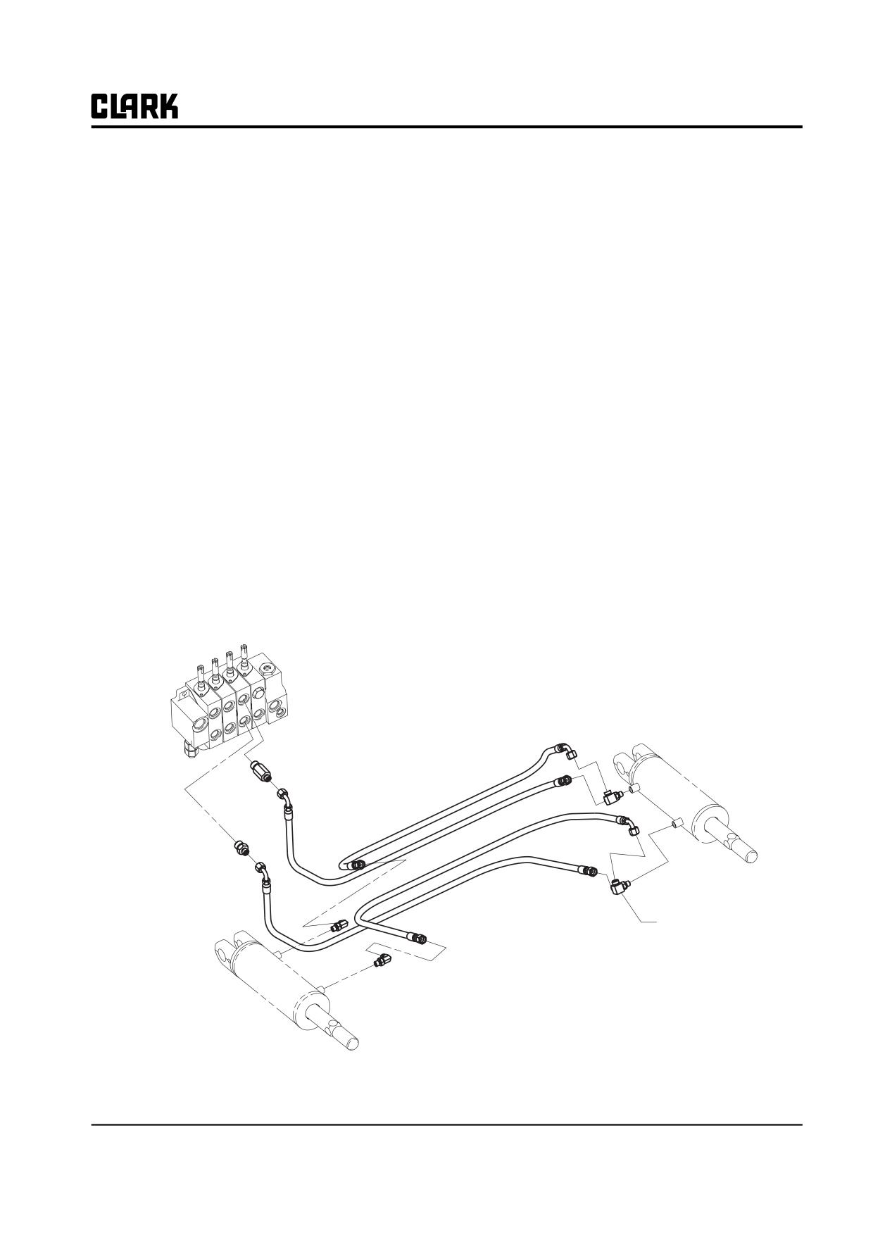
4. Put a drain pan under the truck at each tilt cylinder
switch OFF and remove key.
position before removing the hydraulic lines. Discon-
nect and cap hydraulic lines from the tilt cylinders
4. Apply the parking brake and block the
(see illustration on facing page). Remove the hose
wheels.
connections on both sides of the tee fittings of theri-
ghtside cylinder. Keep all fittings and ports clean.
Tilt Cylinder Removal
1. Move tilt lever back and forth several times to relieve
any pressure.
2. Use an adequate chain and hoist to support the
upright so that it cannot fall when tilt cylinder pins
are removed.
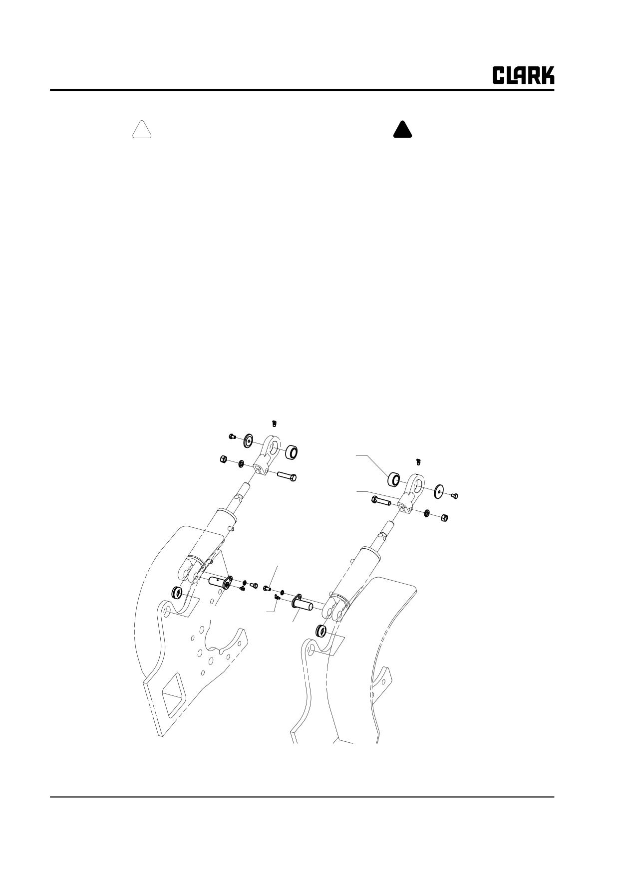
Bearing
Rod-End Yoke
Base Pin
Mounting Bolt
Grease Fitting
Base Pin
Tilt Cylinder Mounting Components
5. Support cylinder with a sling to prevent the cylinder
from dropping when pins are removed.
32-3-2 • Tilt Cylinder Removal and Replacement
SM 765, Nov ’06
Group 32, Tilt Cylinders
6. Remove lock-plate from tilt cylinder rod-end yoke.
Tilt Cylinder Replacement
Use a soft drift and hammer to tap rod-end pin out of
yoke.
1. Position tilt cylinder base yoke on frame mounting
bracket.
7. Pop the cover from tilt cylinder base access port on
the step to the operator’s compartment.
2. Insert base pin in cylinder base yoke and through
frame mounting bracket, making sure slot in pin is in
8. Remove the lock-plate from cylinder base yoke. Use
line with the lock-plate. Grease fitting must point
a soft drift and hammer to tap pin out of yoke.
toward center of truck.
9. Remove cylinder assembly.
IMPORTANT
Make sure the spherical bearing is aligned so
Parts Inspection
that pin fits smoothly in yoke.
1. Clean all bearings, pins, and other components in an
3. Install base pin lock-plate in slot and fasten to yoke
approved cleaning fluid.
with fastener. Tighten fastener to a torque of 40-45
2. Inspect all parts for scratches, nicks, dents, and wear.
N⋅m (30-33 ft-lb).
Check the cylinder rods to be sure they are smooth
4. Position rod-end yoke on upright mounting bracket
with no scratches. Check all threaded parts for dam-
and insert rod-end pin, making sure lock-plate slot is
age.
in correct position. Grease fitting must be toward
3. Replace all parts which show damage.
center of truck. Make sure the spherical bearing is
aligned so that pin fits smoothly in yoke.
4. If parts are to be left exposed, coat all mating sur-
faces of parts with a light layer of engine oil.
Tee Fitting
Till Cylinder Hydraulic Fittings
SM 765, Nov ’06
Tilt Cylinder Removal and Replacement • 32-3-3
Group 32, Tilt Cylinders
NOTE
6. Install tilt cylinder hydraulic lines. Check Group 40
If the rod-end yoke has been removed from
for hydraulic fitting tightening procedures. O-rings
the rod or loosened for adjustment, reinstall
of fittings should be lightly coated with clean
the clamp bolts to a torque of 166-193 N.m
hydraulic fluid or compatible oil.
(122-142 ft-lb). Nuts must be on inside of
7. Remove hoist chain from upright.
upright rails Orientation of the rod-end yoke
bolt hole is to be up as shown on the left side
8. See Section 2 for tilt cylinder adjustment procedures.
of the illustration on the previous page.
When adjustments are made, check all upright com-
ponents under load before returning the truck to ser-
5. Install rod-end lock-plate in slot and fasten to yoke
vice. Nuts must be on inside.
with fastener and washer. Tighten fastener to a torque
of 40-45 N⋅m (30-33 ft-lb).
32-3-4 • Tilt Cylinder Removal and Replacement
SM 765, Nov ’06
Group 32, Tilt Cylinders
Section 4
Tilt Cylinder Overhaul
Preparation for Disassembly
2
Disassembly
2
Inspection
3
Reassembly
3
IMPORTANT
Before removing any component for overhaul, make sure the
correct repair parts, seals, and gasket sets are available.
4
3
6
9
5
7
8
2
1
13
11
12
10
14
15
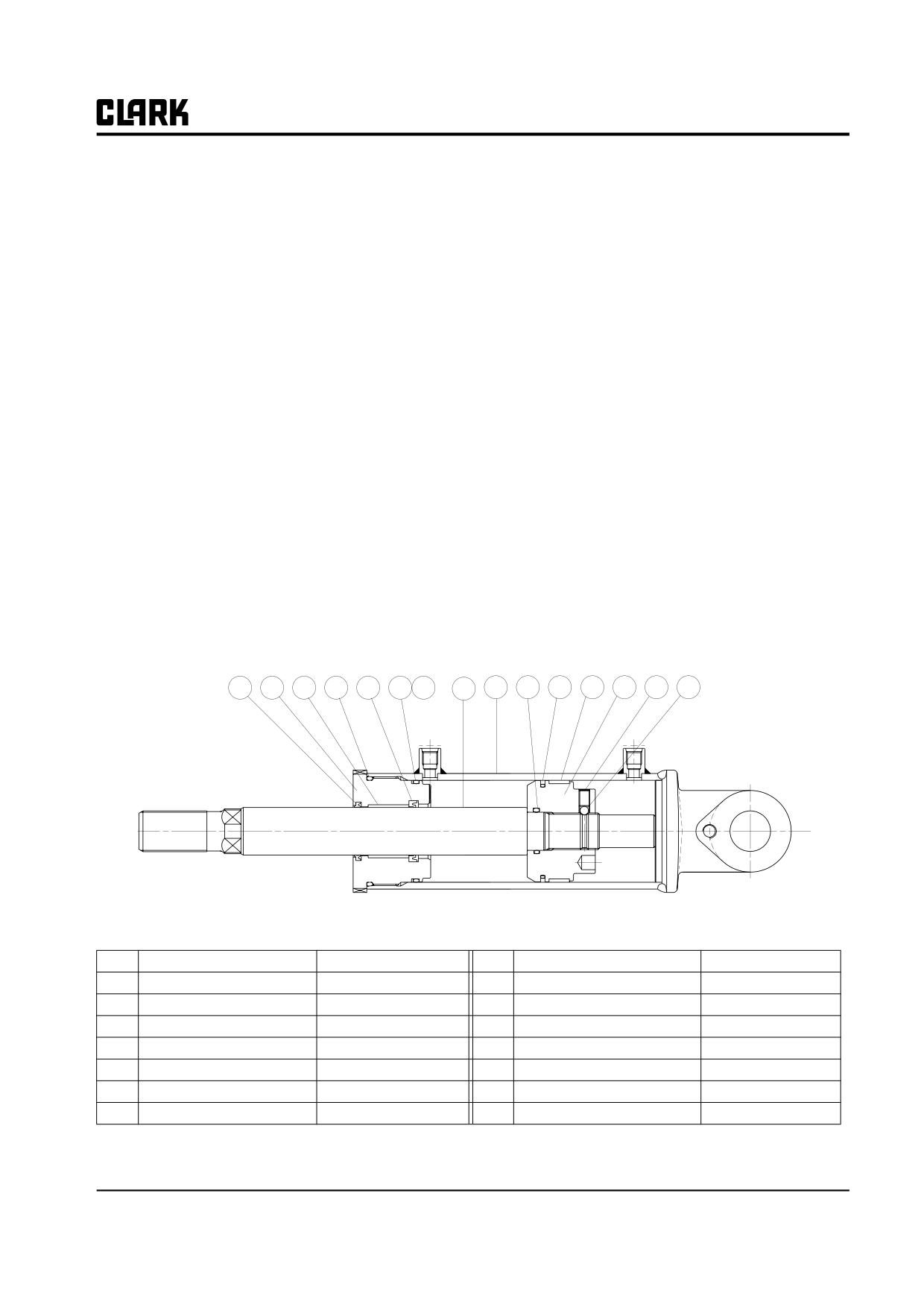
Typical Tilt Cylinder Cross section
1
Tube Assy
9
O-ring
1B G75
2
Rod
10
Piston
3
Gland
11
Piston Seal
4
Dust Wiper
12
Wear Ring
5
Rod Seal
13
O-ring
6
Du Bush
14
Set Screw
7
O-Ring
15
Steel Ball
8
Back up ring
SM 765, Nov ’06
Tilt Cylinder Overhaul • 32-4-1
Group 32, Tilt Cylinders
2. Carefully pull the rod, piston assembly, and gland
Preparation For Disassembly
from the cylinder barrel. Remove gland from rod.
IMPORTANT
Overhaul tilt cylinders only in a clean, dust-
!
WARNING
free location, using clean tools and equip-
The use of compressed air to blow the piston
ment. Dirt or grit will damage the highly-
out of the barrel is not recommended. High-
machined surfaces and will result in leakage
pressure air can result in piston and rod
or premature failure of components. Cleanli-
being ejected at high velocity (explosively),
ness of the hydraulic circuit is extremely
causing severe injury to personnel and prop-
important to the proper operation and main-
erty damage.
tenance of the system. Be sure the work area
is clean.
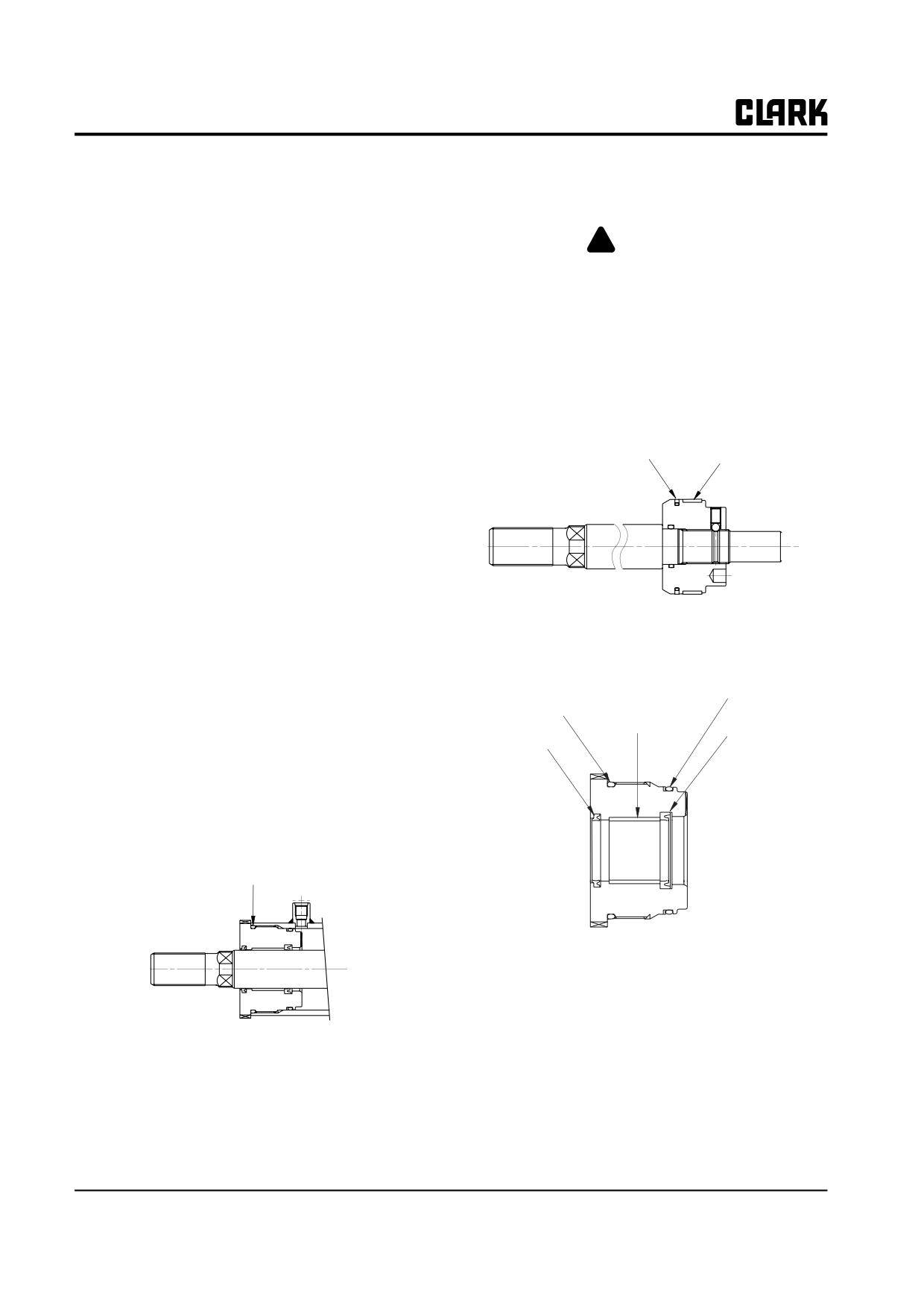
3. Remove and discard the piston packing and wear
rings from the piston.
1. Before disassembly, the exterior of the tilt cylinder
should be carefully cleaned to remove all dirt and
Piston Seal
Wear Ring
grease accumulation.
2. Be sure all hydraulic oil has been removed from the
cylinder. Stroking the piston rod will help force the
oil out.
3. Before starting disassembly, the tilt cylinder should
be carefully examined to determine if there is any
evidence of external damage.
4. Remove and discard the rod U-cup seal, O-ring, and
Disassembly
piston rod wiper from the gland.
The tilt cylinder can be held by clamping the base end or
the barrel in a vise while disassembling.
O-Ring + Backup Ring
O-Ring
IMPORTANT
DU Bush
Rod Wiper
Do not use excessive force when clamping on
Dust Wiper
the barrel.
1. Remove the gland with a hook wrench. Carefully
pull the gland assembly from the cylinder tube and
slide it off the cylinder rod.
O-Ring
32-4-2 • Tilt Cylinder Overhaul
SM 765, Nov ’06
Group 32, Tilt Cylinders
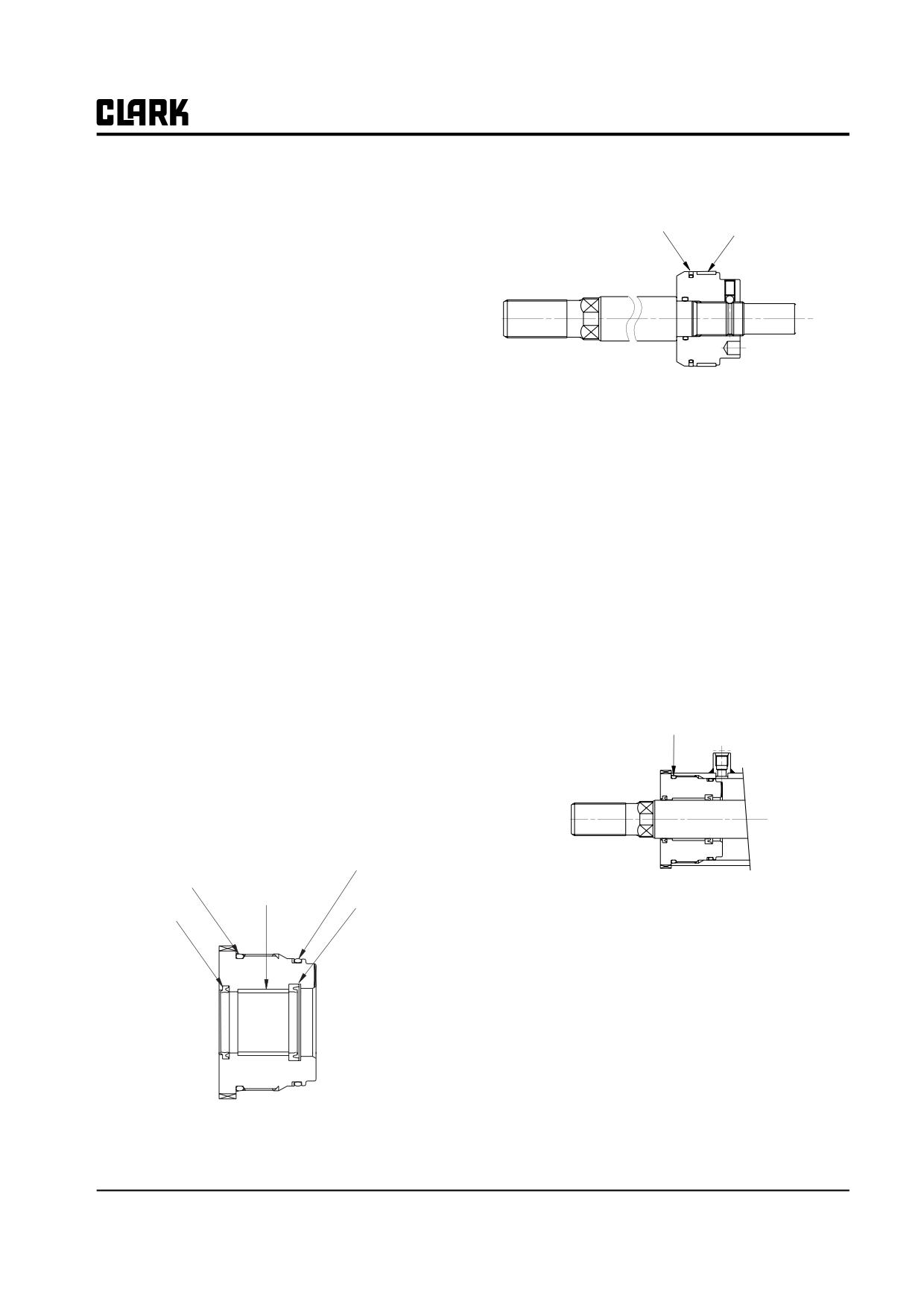
2.
Replace the piston packing and wearing.
Inspection
1. Carefully clean all parts in an approved solvent and
Piston Seal
Wear Ring
place on a clean surface.
2. Check the piston and rod for damage. Look for
gouges, scratches, corrosion, or evidence of unusual
wear. Minor surface damage may be repaired by use
of fine abrasion cloth or stoning. Deeper damage will
require replacement of piston rod assembly.
3. Be sure the threads on rod are undamaged.
4. Inspect the tilt cylinder barrel internal bore for wear,
3.
Install gland on piston rod. Use gentle pressure and
scratches or other damage. Check the outside for
careful movements to avoid damage to the U-cup
damage. Inspect all welds for cracks.
seal and rod wiper when these parts are moved over
Deep gouges or pitted surfaces require replacement
the piston rod end.
of parts.
NOTE
Check the gland, base end, and ports for cracks or
damage that could cause failure. Inspect the ports to
Reassemble cylinder carefully to prevent
be sure they are free of contamination and that the
damage to seal lips and O-rings.
threads are clean and not damaged.
4.
Install piston into cylinder barrel. Be careful not to
5. Put a light coating of hydraulic fluid on all parts. If
damage the piston seals when installing the piston
parts are to be left disassembled for a period of time,
into end of cylinder.
e.g., overnight, they should be covered with a clean
cloth.
5.
Install gland into cylinder them screw the gland into
the cylinder barrel with a hook wrench. When tight-
ing, do not damage the seal. Tighten torque : 60±6
Reassembly
kgf⋅m
Be sure inside of cylinder and all parts are clean before
starting reassembly. Seals may be lubricated with hydrau-
O-Ring
lic oil to assist assembly into cylinder barrel.
1. Install piston dust wiper, rod seal, and O-ring on the
gland. Make sure rod seal and dust wiper are
installed in proper orientation as shown in the illus-
tration.
O-Ring + Backup Ring
O-Ring
DU Bush
Rod Wiper
Dust Wiper
6.
Check the assembly by making sure the piston slides
freely in and out of the cylinder.
See Section 3 for replacement procedures ; see Section 2
for checks and adjustments before returning the truck to
service.
SM 765, Nov ’06
Tilt Cylinder Overhaul • 32-4-3
NOTE :
Group 32, Tilt Cylinders
SM 765, Nov ’06
GROUP 34
GROUP 34
UPRIGHTS
Upright Specifications and Description
Section 1
Troubleshooting
Section 2
Upringht Inspection
Section 3
Carriage and Upright Roller Clearance
Checks and Shim Adjustments
Section 4
Cylinder Removal, Shimming,
Overhaul, and Replacement
Section 5
Upright Chain Inspection, Adjustment,
and Replacement
Section 6
Fork and Carriage Removal and
Replacement
Section 7
Upright Removal and Replacement
Section 8
IMPORTANT
Related service information is covered in Group 29, “Hydrau-
lic Sump, Filters, and Pump,” Group 30, “Hydraulic Control
Valve/Lift Circuit,” and Group 32, “Tilt Cylinder.”
SM 765, Nov ’06
Group 34, Uprights
NOTE :
Group 34, Uprights
SM 765, Nov ’06
Group 34, Uprights
Section 1
Upright Specifications and Description
General Specifications
Upright
Upright Weight: (Approximately 359 kg (792 lb) to
Upright Type Number Cylinder Type
approximately 993 kg (2190 lb) without carriage.
<GEX20-30>
Carriage Weight: Approximately 89 kg (196 lb) to 99 kg
STD Pneu
V2324
Piston-Type Lift Cylinder
(220 lb) with a 41 inch carriage.
TSU Pneu
M2324
Piston-Type Secondary Cylin-
der
Fork Weight: Approximately 44 to 99 kg each (97 to 220
Hi-Lo Pneu H2317
Ram-Type Secondary
lbs).
Cylinder
IMPORTANT
Before hoisting, the weights of upright, car-
Drift:
riage, forks and attachments being lifted
With the upright substantially vertical the descent of the
must be combined to determine what lifting
rated load caused by an internal leakage in the hydraulic
capacity is required of the hoisting equip-
system shall not exceed 100mm (4in) during the first
ment.
10min with the oil in the hydraulic system at normal oper-
ating temperature. If drift over 100 mm (4 in) in ten min-
Capacities and Lift Heights: Upright, carriage, and fork
utes is evident, cylinder should be checked for internal
capacity and upright lift heights are listed on the truck’s
leakage. See Section 3 for drift test procedures.
data plate.
Lubricants:
Fastener and Fitting Torque Specifications
• All Purpose Grease (MS-9)
Pin Mounting Bolts: 280~320 N⋅m (205~234 ft-lb)
• Innerslide Lubricant (Clark P/N 886396)
Load Back Rest: 215-264 N⋅m (159-195 ft-lb)
• Chain and Cable Lube (Clark P/N 886399)
Chain Anchor Bolt Jam Nut: 100-200 N⋅m (74-148 ft-lb)
Carriage Side-Thrust Roller Bolts(External): 40-50 N⋅m
Cylinder Types
(29.5-37 ft-lb)
Standard uprights use two lift cylinders. Triple stage and
Carriage Side-Thrust Roller Bolts(Internal): 70-80 N⋅m
Hi-Lo uprights use three cylinders, a primary (center-
(52-59 ft-lb)
mounted) cylinder, and two secondary cylinders. All pri-
Hose Fittings: See Group 40, “Hydraulic Fitting Tighten-
mary cylinders used on triple-stage uprights (TSUs & Hi-
ing Procedure.”
Lo) are piston cylinders. The lift and secondary cylinders
used on standard, Hi-Lo uprights and TSUs can be piston
Rod End Bolts: 170-190 N⋅m (125-140 ft-lb)
cylinders.
Tilt Cylinder Rod-End Pin Lock Plate: 40-45 N⋅m (30-33
ft-lb).
The types of cylinders used on the truck are listed below.
Check the first five characters of the upright number
stamped on the upright of the truck to determine the type
Service Intervals
of cylinder, piston used on the upright.
• All upright components should be visually checked
every day during the Operator’s Daily Inspection.
IMPORTANT
• A thorough visual inspection should be performed
Before removing any component for over-
by a trained service professional every 50-250
haul, make sure the correct repair parts,
hours.
seals, and gasket sets are available.
• Lift chains should be inspected and lubricated
every 50-250 hours or monthly.
SM 765, Nov ’06
Upright Specifications and Description • 34-1-1
Group 34, Uprights
• Lift chain tension should be checked every 50-250
Piston-type cylinders contain a by-pass check valve in the
hours or monthly.
piston that allows air and fluid that have accumulated in
• Upright and carriage roller checks should be per-
the rod end of the cylinder to return to the system. The
formed every 50-250 hours or monthly.
check valve can be removed and cleaned if indicated by
troubleshooting. A non-serviceable check-ball-type cush-
• Roller patterns should be checked every 6 months
ioning function is built into ram and piston cylinders for
or after 1000 hours of service.
smooth staging during the lowering cycle. The primary
• Racking and drift tests should be performed every
cylinder on TSUs incorporates cushioning on the lift
50~250 hours or monthly.
cycle. A velocity fuse in the hydraulic port of the lift cyl-
• The complete extended inspection should be per-
inders (secondary cylinders on TSUs) prevents the mast
formed at least every year or 2000 hours of opera-
from falling rapidly in case of sudden fluid pressure loss
tion.
due to line breaks or other malfunction of the hydraulic
circuit.
Description
As the cushion system is added to lift cylinder of standard
The upright assembly includes the lift chains, lift cylin-
upright and the 1st cylinder of TSU, the speed will get
ders, carriage, forks, and mast or rail sets. Each of the
slow for a moment before the fork touches the ground. It
components can be serviced using the tests, checks,
is helpful to protect the ground.
adjustments, and removal and replacement procedures in
the following Sections.
As explained in more detail in Group 30, the main pump
sends fluid to the main hydraulic control valve, which
The upright uses the hydraulic cylinders and chain sets to
contains spools that route fluid to the lift cylinders and tilt
lift the carriage and rail sets. On standard, two-stage
cylinders. The valve assembly also contains a counter-
uprights, the lift cylinders lift the carriage with chains and
balance valve that prevents upright tilt when the truck is
directly lift the inner rail set. On triple-stage uprights, the
not operating.
primary (free-lift) cylinder lifts the carriage by chains.
When the primary cylinder reaches its maximum exten-
Fluid flow rates for lift functions are factory set and not
sion, fluid is diverted to the secondary lift cylinders,
adjustable. Flow rates for tilt and auxiliary functions are
which lift the inner rails using a second set of chains and
controlled by adjustments on the main hydraulic valve. A
lift the intermediate rails by direct lift.
non-adjustable “load-lowering” flow valve mounted on
the upright limits upright lowering speed.
On Hi-Lo uprights, the primary(free-lift) cylinder lifts the
carriage by chanis. The secondary cylinders directly lift
Groups 29 and 30 contain general hydraulic information
the inner rail set by rod. Hi-Lo uprights not used second
including upright hydraulic functions. Other hydraulic
set of chain for secondary cyliner.
checks for the upright appear in “Troubleshooting,” Sec-
tion 2.
Friction and play between the nesting rails is controlled by
roller sets mounted on the rails and carriage. When rails or
rollers become worn, the gap between the rollers and rails
becomes larger, creating more play in lifting and lowering
operations. The rail web to roller side clearances can be
reduced by shimming the rollers to close the gap between
the roller and rails. The gap between the rail flange and
roller bearing surface can be reduced by the use of over-
size rollers on a one-time basis.
Forks use a hanger design for mounting on the carriage.
Auxiliary attachments may be added to the upright for
specialized handling operations. The hydraulic circuit is
modified with a hose adapter kit and an auxiliary section
is added to the main hydraulic valve to operate the attach-
ment.
The lift and secondary cylinders on standard uprights and
triple-stage uprights (TSUs) are piston type cylinders. The
primary cylinder on TSUs and HILO are piston-type cyl-
inder. See the chart under “Specifications” to determine
the type of cylinder used on the upright you are servicing.
34-1-2 • Upright Specifications and Description
SM 765, Nov ’06
Group 34, Uprights
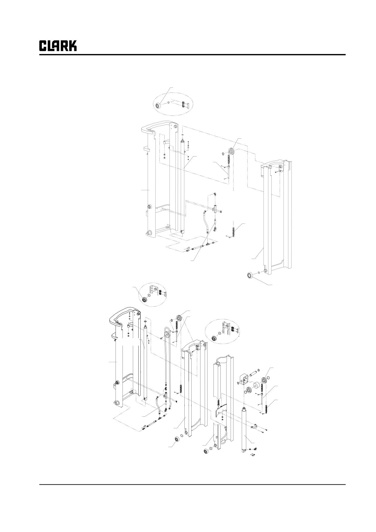
Upper Roller
*Assembly of slider and adjustment of shim:
Assemble the slider as the backside of rail and the
friction surface of slider are in parallel.
Match the outer rail end and inner rail end, and then
make the gap between the flange face of inner rail
and the slider will be within 0.5mm.
Chain Sheave
Lift Cylinder
Chain Anchor
Outer Rail Set
Lift Chain
Load Lowering
Inner Rail Set
Flow Valve
Typical Standard Upright Assembly
Upper Roller
*Assembly of slider and adjustment of shim:
Lower Roller
Assemble the slider as the backside of rail and the
friction surface of slider are in parallel.
Match the outer rail end and inter rail end, and then
make the gap between the flange face of inter rail
and the slider will be within 0.5mm.
Chain Sheave
Chain Anchor
*Assembly of slider and adjustment of shim:
Assemble the slider as the backside of rail and the
friction surface of slider are in parallel.
Match the Inter rail end and inner rail end, and then
make the gap between the flange face of inner rail
Secondary
and the slider will be within 0.5mm.
Cylinder
Outer Rail Set
Chain Sheave
Chain
Anchor
Carriage Chain
Load Lowering
Flow Valve
Inter Rail Set
Primary Cylinder
Lower Roller
Inner Rail Set
Typical Triple Stage Upright Assembly
SM 765, Nov ’06
Upright Specifications and Description • 34-1-3
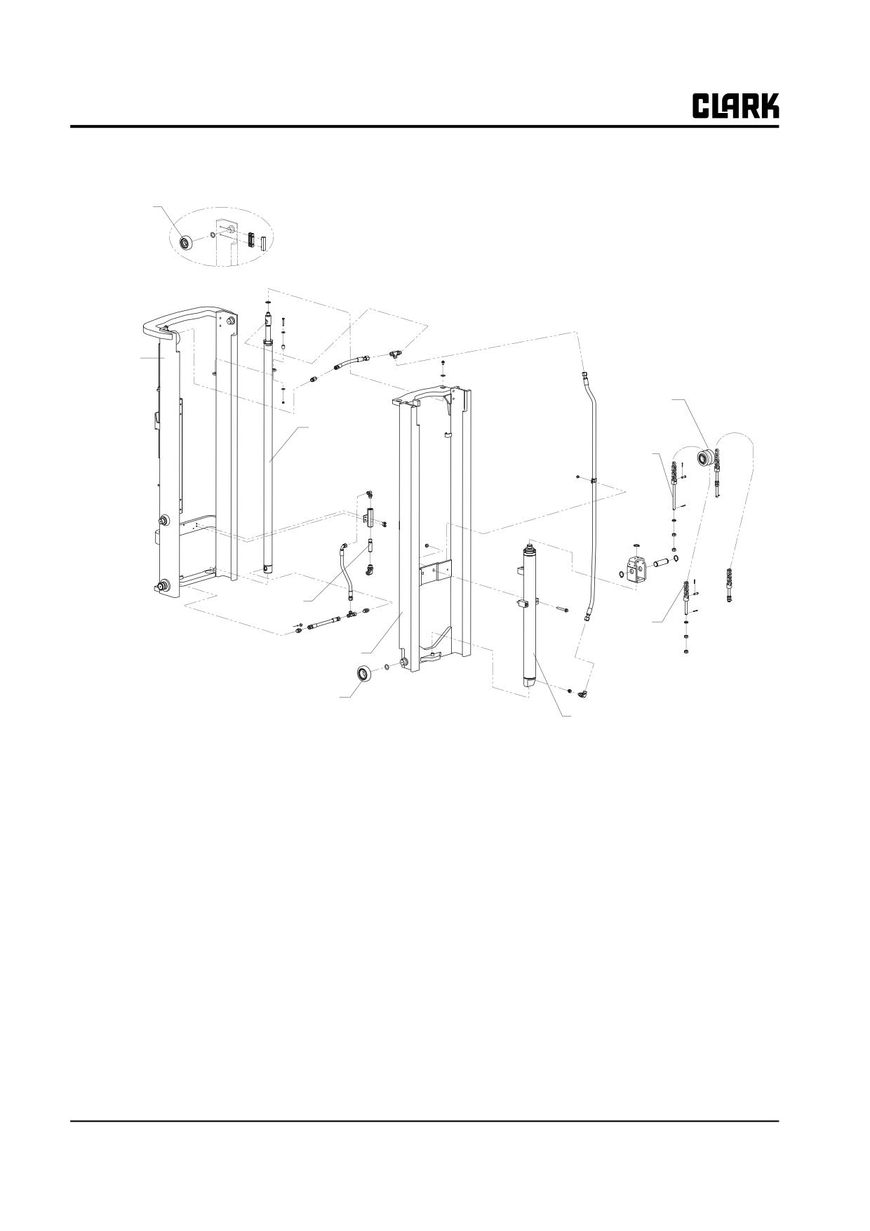
Group 34, Uprights
Upper Roller
*Assembly of slider and adjustment of shim:
Assemble the slider as the backside of rail and the
friction surface of slider are in parallel.
Match the outer rail end and inner rail end, and then
make the gap between the flange face of inner rail
and the slider will be within 0.5mm.
Outer Rail Set
Chain Sheave
Secondary
Cylinder
Chain Anchor
Load Lowering
Flow Valve
Lift Chain
Inner Rail Set
Lower Roller
Primary Cylinder
Typical Hi-lo Upright Assembly
34-1-4 • Upright Specifications and Description
SM 765, Nov ’06
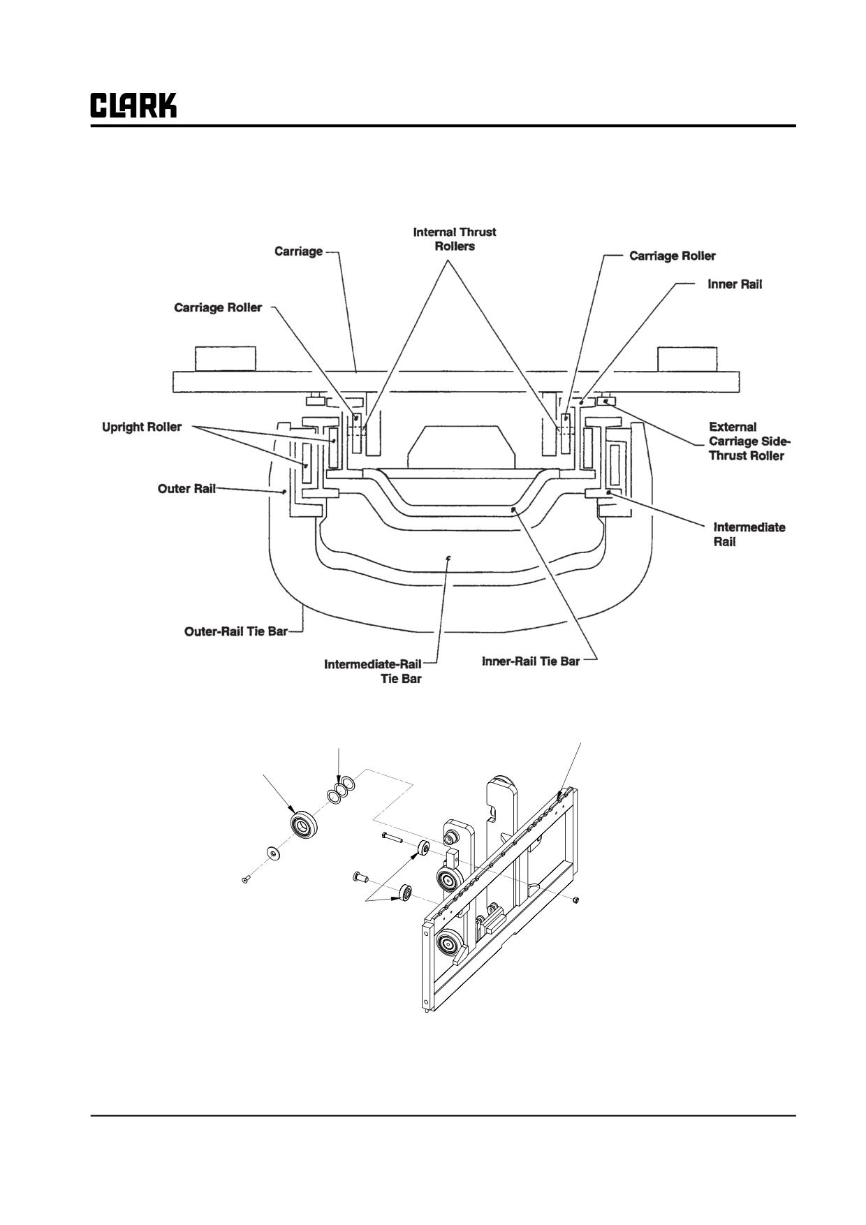
Group 34, Uprights
Typical Triple Stage Upringht-Overhead View
Shim
Carriage
Roller
Side thrust Roller
Carriages and Roller Sets
SM 765, Nov ’06
Upright Specifications and Description • 34-1-5
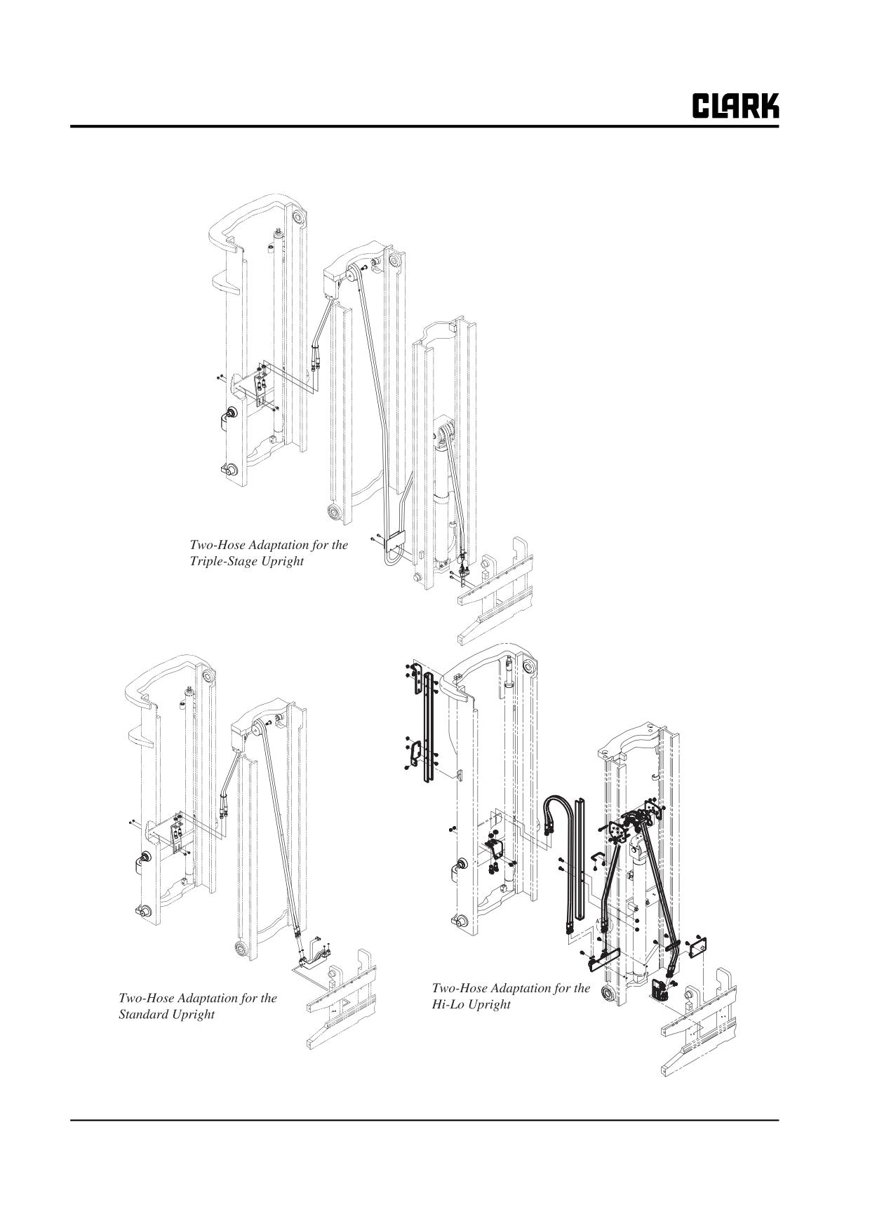
Group 34, Uprights
34-1-6 • Upright Specifications and Description
SM 765, Nov ’06
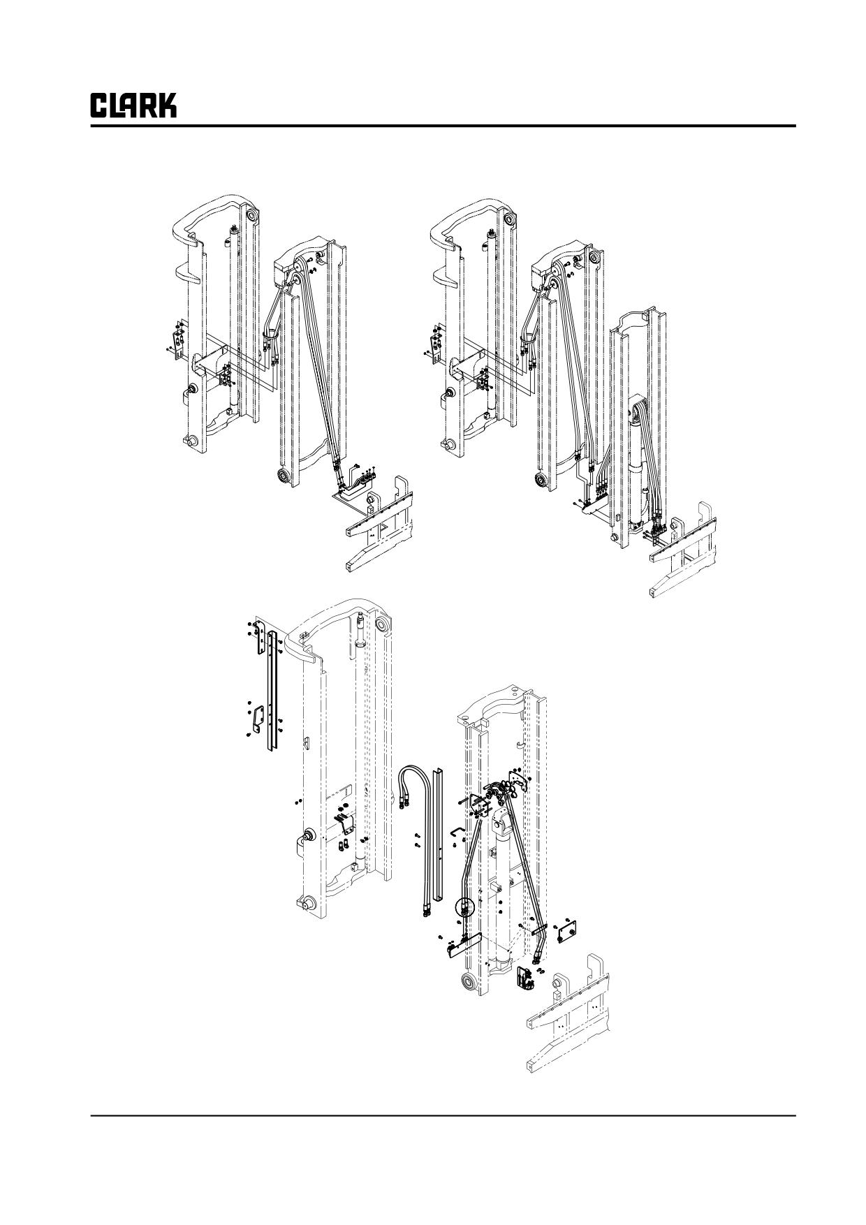
Group 34, Uprights
Four-Hose Adaptation for the
Standard Upright
Four-Hose Adaptation for the
Triple-Stage Upright
Four-Hose Adaptation for the
Hi-Lo Upright
SM 765, Nov ’06
Upright Specifications and Description • 34-1-7
NOTE :
Group 34, Uprights
SM 765, Nov ’06
Group 34, Uprights
Section 2
Troubleshooting
The visual inspection and the operational checks pre-
• Dry hose sheave or rollers; check condition of all
sented in Section 3 should be used to determine problems
sheaves and rollers and lubricate as necessary.
with the upright. Possible problems, causes, and remedies
• Damaged chain sheaves; check condition of chain
are listed below.
sheaves and repair or replace.
Other troubleshooting information about the hydraulic cir-
• Excessive fork hanger or carriage fork bar wear;
cuit and components appears in the troubleshooting Sec-
inspect and replace as necessary.
tions of Groups
29 and
30. Use these other
• Seals dry; lubricate rod.
troubleshooting Sections for more detailed problem isola-
• Seals dry - all primary cylinders; remove gland and
tion with Upright hydraulic functions.
add 100 ml (3.4 oz) of hydraulic oil to rod side of
piston, see “Cylinder Removal, Shimming, Over-
! WARNING
haul, and Replacement.”
The procedures for troubleshooting uprights,
carriages, and forks involve movement of the
No lift, tilt, or auxiliary function
components. Failure to follow these warnings
can result in serious injury.
• Hydraulic fluid level low; check level and fill.
Make sure overhead clearances are adequate
• Broken hoses or fittings; check and repair.
before raising the upright to full lift height.
• Damaged or blocked sump strainer; check and
Do not walk or stand under raised forks.
clean.
Block carriage and upright whenever making
checks with the upright elevated.
• Hydraulic pump defective; see Group 29 for pump
Keep clear of load and carriage when making
troubleshooting.
any check or adjustment.
• Defective main hydraulic control valve; see Group
Keep your arms and fingers away from mov-
30 for valve troubleshooting.
ing parts of the upright.
• Defective upright load-lowering flow valve; disas-
Do not reach through open areas of the
semble valve, check and clean or replace.
upright.
No lift function but tilt operates
Upright noise
• Broken hoses or fittings; check and repair.
• Bent or broken components; inspect upright thor-
• Cylinder is damaged; inspect and repair.
oughly and repair or replace components as
required.
• Main hydraulic control valve, lift section defective;
see Group 30 for valve troubleshooting and ser-
• Damaged upright roller; check condition of rollers
vice information.
and replace defective rollers.
• Upright load-lowering flow valve damaged; disas-
• Roller scuffing rails; clean and lubricate rails.
semble valve, check and clean or replace.
• Roller (carriage or upright) shimming needs
adjustment; check and adjust as required.
• Fit between roller edge and rail flange excessively
loose in rails; replace with oversized, “Select-Fit”
rollers. See “Upright Roller Clearance Check and
Shim Adjustment.”
• Dry lift chain; lubricate chain.
SM 765, Nov ’06
Troubleshooting • 34-2-1
Group 34, Uprights
Load cannot be lifted to maximum height
• Defective priority valve; see Group 30 for valve
troubleshooting information.
• Hydraulic fluid level low, check level and fill.
• Defective upright load-lowering flow valve;
• Debris in upright; check and clean.
remove valve clean, inspect, and replace if neces-
• Hydraulic hose fittings loose or damaged; check
sary.
and torque correctly (see Group 40 for specifica-
tions) or replace.
Lowering speed sluggish
• Check cylinder for external leakage; replace cylin-
• Damaged or binding upright roller; check condi-
der if cracked.
tion of roller and replace if necessary.
• Cylinder shimming is incorrect; check and adjust
• Damaged or kinked hydraulic hose or tube; check
shimming.
condition of hose and tube, repair or replace as
• Internal leakage on lift or secondary piston cylin-
necessary.
ders; remove rod and piston and clean check
• Defective upright load-lowering flow valve; check,
valves; also clean and inspect/replace piston seals.
clean and replace valve if necessary.
See Section 5.
• Defective velocity fuse; remove fuse from cylinder
• Cylinder check valve on lift or secondary piston
hydraulic port, clean and recheck for proper opera-
cylinders not functioning properly; remove rod and
tion.
piston and clean check valves; also clean and
inspect/replace piston seals. See Section 5.
Load bounces excessively when lowering
• Hydraulic pump defective; see Group 29 for pump
• Air in hydraulic system, TSU and Hi-Lo ram-type
troubleshooting information.
cylinders; set capacity load on upright and lift form
• Upright rails binding:
fully collapsed to full lift height for 10-15 cycles.
a. Perform a visual inspection and check for worn,
• Defective upright load-lowering flow valve; check,
or distorted parts, broken or cracked rails or tie-
clean and replace valve if necessary.
bars, correct chain and hosing placement and
operation
• Defective main lift valve; see Group 30 for valve
b. Check rollers for contamination and proper oper-
troubleshooting and service information.
ation, perform roller clearance check and adjust-
• Defective velocity fuse; remove fuse from cylinder
ment
hydraulic port, clean and recheck for proper opera-
tion.
Lift speed sluggish
Upright mis-staging (TSU lifting)
• Hydraulic fluid level low; check level and fill.
• Debris in upright roller area of carriage; check and
• Broken hoses or fittings; check and repair.
clean.
• Pump inlet line restricted; remove from pump and
• Interference between carriage and inner rail or cyl-
clean.
inder; check staging alignment and adjust or repair
• Damaged or binding upright roller; check condi-
as necessary.
tion of roller and replace if necessary.
• Bent or broken carriage or inner rail; replace part -
• Internal leakage on piston-type lift and secondary
do not try to repair by welding.
cylinders (with load); perform cylinder checks
• Damaged or binding carriage roller; check condi-
listed under “Load cannot be lifted to maximum
tion of roller and replace if necessary.
height.”
• Carriage roller shimming or thrust roller out of
• Hydraulic pump defective; see Group 29 for pump
adjustment; perform roller checks on carriage and
troubleshooting information.
make adjustments as necessary.
• Defective main lift valve; see Group 30 for valve
• Damaged or kinked primary cylinder hose; check
troubleshooting and service information.
condition of hose, repair or replace as necessary.
• Defective velocity fuse; remove fuse from cylinder
• Primary cylinder chain or chain sheave binding or
hydraulic port, clean and recheck for proper opera-
damaged; inspect and repair.
tion.
34-2-2 • Troubleshooting
SM 765, Nov ’06
Group 34, Uprights
• Internal leakage in primary lift cylinder; perform
• Bent or broken carriage or inner rail; replace part -
cylinder checks listed under “Load cannot be lifted
do not try to repair by welding.
to maximum height.”
• Carriage and upright roller shimming or thrust
• Damaged primary lift cylinder causing binding in
roller out of adjustment; perform roller checks on
the cylinder; inspect and repair or replace cylinder.
upright and/or carriage and make adjustments as
necessary.
• Defective velocity fuse; remove fuse from cylinder
hydraulic port, clean and recheck for proper opera-
• Defective velocity fuse; remove fuse from cylinder
tion.
hydraulic port, clean and recheck for proper opera-
tion.
Upright mis-staging (TSU lowering)
External leakage on primary cylinder
• Debris in upright roller area or tie bar area; check
and clean.
• Gland loose; check and tighten primary cylinder
gland to 588 N⋅m (432 ft-lb) and glands on lift
• Bent or broken carriage or inner rail; replace part -
(secondary) cylinders to 392 N⋅m (289 ft-lb).
do not try to repair by welding.
• Cracked cylinder tube; replace tube.
• Damaged or binding roller on upright; check con-
dition of roller and replace if necessary.
• Rod seal damage; replace seals and check for:
- Damaged rod seal groove in gland; check for
• Carriage and upright roller shimming or thrust
damage to groove and replace seal or gland if
roller out of adjustment; perform roller checks on
necessary
upright and/or carriage and make adjustments as
- Scored cylinder wall; repair or replace cylinder
necessary.
tube if necessary
• Damaged or kinked lift cylinder hose; check condi-
- Leaking check valve; clean and replace if nec-
tion of hose, repair or replace as necessary.
essary
• Lift cylinder chain or chain sheave binding or dam-
- Leaking O-ring seal on check valve; replace
aged; inspect and repair.
check valve.
• Bent cylinder rod; inspect and replace rod and/or
• Gland static seals (O-rings and back-up ring) dam-
cylinder as necessary.
aged; replace back-up ring.
• Internal leakage in piston-type cylinders; perform
• Gland static seals sealing surface damaged; check
cylinder checks listed under “Load cannot be lifted
groove and bore and repair or replace as necessary.
to maximum height.”
• Damaged lift cylinder causing binding in the cylin-
External leakage on lift (Standard) and
der; inspect and repair or replace cylinder.
secondary cylinder (TSUs and Hi-Lo)
• Defective velocity fuse; remove fuse from cylinder
hydraulic port, clean and recheck for proper opera-
• Gland loose; check and tighten gland on cylinders
tion.
to 392 N⋅m (289 ft-lb).
• Cracked cylinder tube; inspect and replace tube.
Upright mis-staging (Standard and Hi-Lo
• Seal damage in piston-type cylinders; replace pis-
upright lowering)
ton seals and rod seals.
• Damaged seal groove, piston-type cylinders; check
• Damaged or binding roller on upright; check con-
for scratches, nicks, or burrs and repair or replace
dition of roller and replace if necessary.
rod and piston.
• Top carriage roller retaining cap screw loose;
• Scored cylinder wall, TSU piston-type cylinders;
check and replace cap screw.
replace tube and all seals.
• Lift cylinder chain or chain sheave binding or dam-
• Scored or damaged rod; replace rod and all seals.
aged; inspect and repair.
• Damaged gland back-up seal; inspect and replace
• Debris in upright roller area or tie bar area; check
seal.
and clean.
SM 765, Nov ’06
Troubleshooting • 34-2-3
Group 34, Uprights
• Gland static seals sealing surface damaged; check
• Cylinder hydraulic fittings loose or worn; check
grooves and bore.
fitting O-rings, tighten fittings according to Group
40, “Hydraulic Fitting Tightening Procedure.”
Oil leak at top of lift cylinder
• Check valve worn or damaged; remove rod and
• Scored cylinder wall; see Section 5.
piston, clean check valve and replace if necessary.
• Worn or damaged gland rod-seal; see procedures
• Control valve spool linkage malfunctioning, dam-
for piston-type cylinders under “Cylinder leaking
aged, or worn; see Group 30, Section 5 for linkage
internally.”
adjustment and/or replacement.
• Counterbalance function in main hydraulic control
Unsatisfactory lift or tilt cylinder drift test results
valve malfunctioning, damaged, or worn; inspect
• Cylinder leaking internally; remove cylinder gland
and clean or replace if necessary.
and check:
a. Primary cylinder should have only 3.4 ounces
(100 ml) on rod side of the piston
b. Piston-type lift and secondary cylinders should be
dry on rod side of piston.
If fluid is leaking past piston:
On piston-type cylinders, remove rod and piston,
clean check valves and clean and inspect/replace pis-
ton seals
See Section 5.
34-2-4 • Troubleshooting
SM 765, Nov ’06
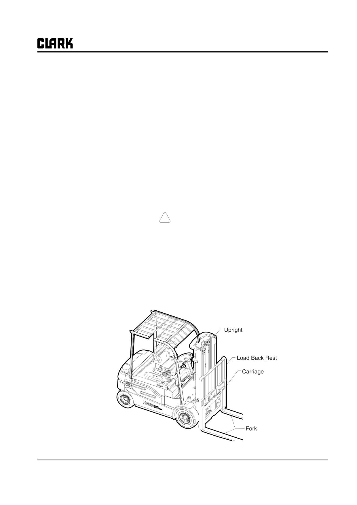
Group 34, Uprights
Section 3
Upright Inspection
!
CAUTION
SAFE PARKING. Before working on truck:
1. Park truck on a hard, level, and solid sur-
face, such as a concrete floor with no gaps or
breaks.
2. Put upright in vertical position and fully
lower the forks or attachment.
3. Put all controls in neutral. turn key switch
OFF and remove key.
4. Apply the parking brake and block the
wheels.
SM 765, Nov ’06
Upright Inspection • 34-3-1
Group 34, Uprights
Basic Visual Inspection
Lift Chains
Use the following steps to conduct an initial visual inspec-
Inspect the chains for:
tion of the upright. This is the same type of inspection
• Proper lubrication. The links should have a coat of
operators should be conducting on a daily basis.
oil on all surfaces. Lubrication oil should penetrate
If you note problems with any component during the basic
completely into chain joints.
visual inspection, continue with “Extended Inspection”
• Good condition of the chain links and pins. No
for checks and service.
rust, corrosion, stiffness, or cracking should be evi-
dent. Pins should not be turned or protruding.
! WARNING
• Excessive side wear or edge wear on the chain
The procedures for checking, maintaining,
plates.
and adjusting uprights, carriages, and forks
• Correct, equal tension on chain sets.
involve movement of the components. Failure
• Secure anchor bolt, adjustment nut, and jam nut
to follow these warnings can result in serious
mounting.
injury. Always use extreme caution.
• Correct alignment of the chain anchors to the chain
Do not walk or stand under raised forks.
and chain sheaves. Adjust turned chain anchors.
Keep clear of load and carriage when making
any check or adjustment.
• Loose, broken, or damaged anchor bolt pins and
Keep your arms and fingers away from mov-
cotter pins. Replace defective pins and cotter pins.
ing parts of the upright.
Do not reach through open areas of the
Rollers
upright.
Inspect the upright and carriage rollers for:
General
• Broken or loose rollers.
• Loose, broken, or misadjusted thrust roller on the
• Check to make sure all fasteners are secure.
carriage.
• Check to make sure the upright lifts and lowers
• Obvious signs of failed bearing seals.
smoothly with and without a capacity load.
• Check for visible damage to components.
NOTE
Some grease will purge from the bearings in
the first 100-200 hours of operation.
Forks
• Check function and security of the fork latch.
• Excessive looseness in carriage or upright roller
shimming.
• Inspect the forks for cracks, especially the hanger
and heel areas.
Upright and Carriage Weldments
• Check for wear in the fork heel. If heel wear is evi-
dent, perform the extended inspection.
Inspect the upright and carriage for:
• Inspect the fork hanger and carriage fork bar for
• Debris or foreign objects on the components.
excessive wear.
• Bent, cracked, or broken components.
• Inspect for bent forks.
• Undesirable wear on or contact between compo-
nents.
Load Backrest
• Irregular roller patterns and signs of excessive
• Inspect load backrest for damage such as cracks or
wear or scraping on the rails.
bending.
• Check for tight mounting fasteners.
34-3-2 • Upright Inspection
SM 765, Nov ’06
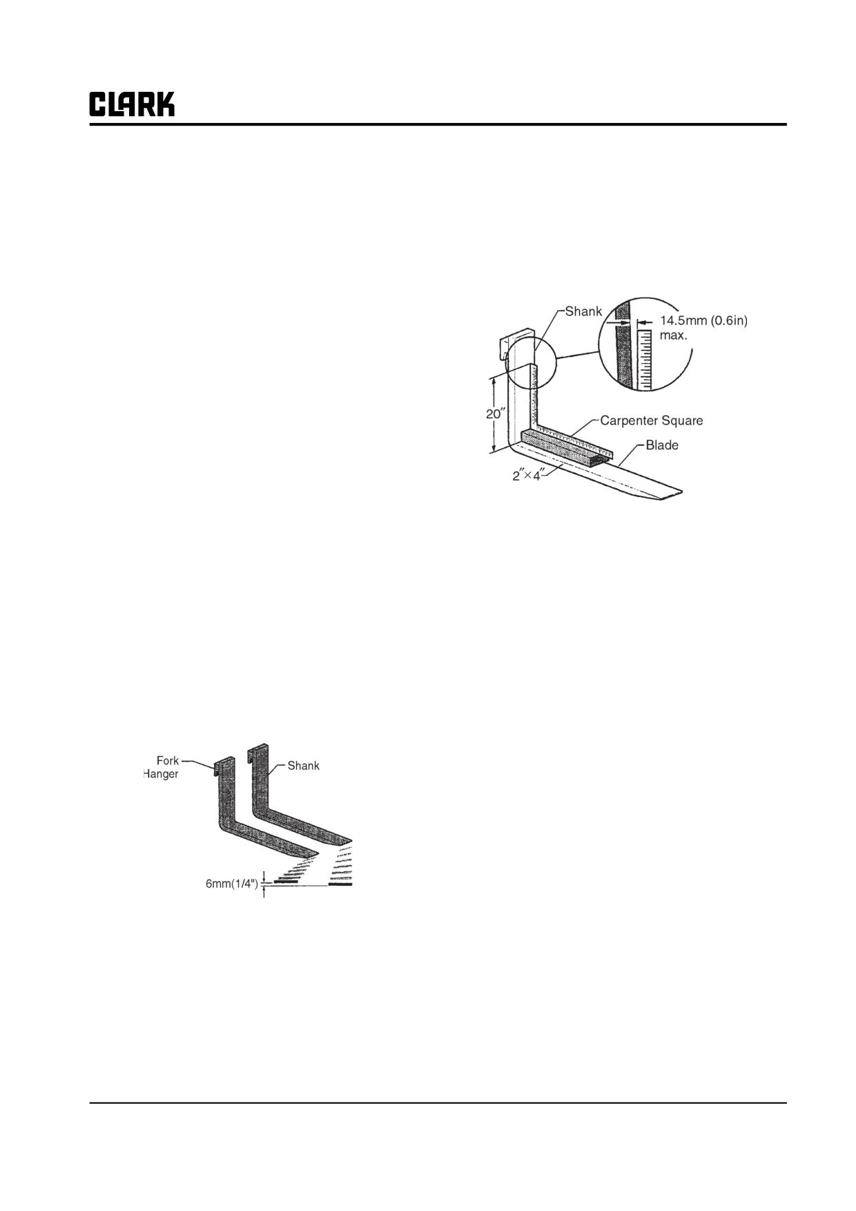
Group 34, Uprights
Hydraulic System
Fork Bending
Overloading, glancing blows against solid objects, or
Inspect the upright hydraulic system components for:
picking up loads unevenly can bend or twist a fork. Use
• Damage or wear on all hoses and hydraulic tubes.
the following procedure to check for fork bending.
• Leaks on hoses, fittings, or valves.
1. Place a 50 x 100 x 610 mm (2 x 4 x 24 in) wood
• Leakage on the cylinders.
block flat on the fork. Make sure the block is not rest-
ing on the heel radius.
• Excessive drift in lift or tilt operations.
Extended Inspection
The extended inspection should be performed whenever
the basic visual inspection indicates upright problems, as
specified for PMs, or at least every 2000 hours.
Forks
Forks have a limited service life because of wear and
fatigue. Forks should be tested every 50-250 hours using a
visual inspection, a fork thickness check, a fork bending
Fork Bending Check
check, and a fork gap check. If replacement is necessary,
always replace the pair to ensure fork integrity.
2. Set a carpenter’s square on the block against the fork
shank
Fork Alignment
3. Check the fork 508 mm (20 in) above the blade to
1. Park the truck on a flat, even surface, tilt upright to
make sure it is not bent more than 14.5 mm (0.6 in) at
vertical position, and set forks 25-50 mm (1-2 in)
the maximum.
above the ground.
4. If blades are bent over the 14.5 mm (0.6 in) allow-
2. Compare fork arms to be sure they are straight, on
ance they should be replaced as a set.
the same plane (level), and the same length.
See Section 7, “Fork and Carriage Removal and Replace-
3. Measure the distance from the fork tips to the
ment,” for procedures to remove and replace the forks.
ground. The height difference between the forks tips
Fork Fatigue
should be no more than 6mm(1/4in).
Fatigue cracks normally start in the heel area or on the
underside of the top hanger. If cracks are found, the fork
should be replaced. Dye penetrants or magnaflux can be
used for a more accurate inspection.
Fork Wear and Heel Wear
Industrial Truck Association (ITA) standards require that
a fork be removed from service when the blade or heel
thickness is reduced by 10% over its original thickness. If
the heel is 10% smaller than the arm, the load capacity
could be reduced by 20%. A 5,000-pound (2272 kg)
Fork Arm Height
capacity fork with 10% wear can only safely handle 4,000
4. If the fork tips are not aligned within the specified
pounds (1818 kg).
6mm (1/4in) difference, the cause of the problem
Use of fork wear calipers are recommended (Clark part
must be determined and corrected before returning
number 1803641) to gauge fork wear as follows:
the truck to service. If replacement is necessary,
always replace the forks in a set.
1. Use the outside jaws of the caliper to measure fork
thickness in the shank area of the fork.
SM 765, Nov ’06
Upright Inspection • 34-3-3
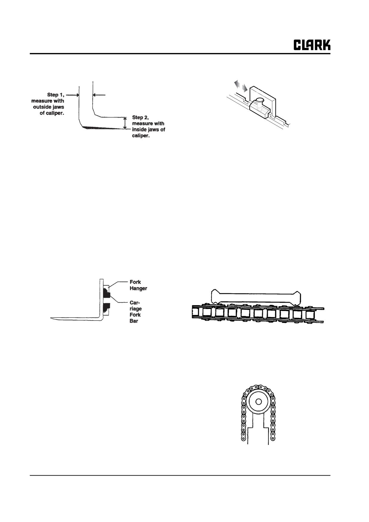
Group 34, Uprights
NOTE
A small amount of lubricant can be applied
NOTE
to the fork latch. Do not over lubricate and
allow lubricant to run down on carriage fork
Hold the caliper square and use light pres-
bar.
sure to squeeze the outer jaw tips against the
fork shank. Take care not to accidentally
2. Check fork stops for widening of notches or round-
alter the reading of the calipers.
ing of top edge. Replace the carriage if fork stops are
excessively worn.
2. Check the fork blade area to the inside jaws of the
caliper.
Lift Chains
3. If the inside jaws fit over the fork in the blade area,
wear exceeds allowable 10% wear and a new set of
The following checks should be performed every 50-250
forks should be installed.
hours to ensure correct chain performance See Section 6
Fork Hanger Wear and Carriage Fork Bar Wear
for more complete chain inspection and maintenance pro-
cedures.
Inspect the fork hangers and carriage fork bar. Excessive
wear can cause the fork to disengage the fork bars or
Chain Wear (Stretch) - All Lift Chains
reduce fork hanger life.
Lift chain stretch due to wear in the joints can be mea-
sured using a measuring tape or Clark’s chain check ruler.
Chain Check Ruler - Clark Part Number 59-960-9908
• If fork hangers are excessively worn, replace the
forks as a set.
When any section of the chain has worn and increased its
• If carriage fork bar is excessively worn, replace the
original length by 3% or more, the chain must be replaced.
carriage.
When checking chain wear, always measure a segment of
the chain that rolls over a sheave.
IMPORTANT
Welding is not recommended for repairing
forks or carriage. Replace the worn parts
with new parts.
Fork Latch and Carriage Fork Stops
1. Check fork latches for proper operation. Latches
should operate smoothly. The spring should be in
good condition and securely lock the fork into posi-
tion. Replace the fork latch if it does not operate
properly.
34-3-4 • Upright Inspection
SM 765, Nov ’06
Group 34, Uprights
IMPORTANT
!
WARNING
Never replace a single chain in a set. Always
replace the two chains in a set for consistent
Do not reach through the upright to push
lift operation. Always replace anchor pins
chains for tension check.
when replacing chains.
3. If one chains moves more than the other;
1. For example, measure a 305 mm (12 in) segment of
a. Lower the forks to ease tension on the chains.
the chain that does not roll over a sheave and count
b. Adjust chain adjustment nuts for equal tension on
the number of links in the segment.
both chains. See Section 6 for chain adjustment
procedures
2. Find an area of the chain that normally runs over the
sheave. This can usually be identified by wear on the
4. Repeat the tension test and make adjustments until
plate edges that roll over the sheave.
the tension is equal on both chains when the carriage
and upright are raised.
3. If the same number of links measures over 315 mm
(12.36 in) the chain must be replaced.
If using a chain check ruler, see instructions on the ruler.
Carriage and Upright Weldments
Chain replacement procedures appear in Section 6.
The carriage and upright should be checked for fatigue
cracks and bent components every 2000 hours or every
Chain Length
year..Fatigue cracks start in areas of stress after a high
IMPORTANT
number of load cycles. Stress concentrations typically
Perform a chain length check and adjust-
exist in welded joints, in the area around a welded joint, or
ment every 50-250 hours. Checks and adjust-
in the corners of parts. Dye penetrant, magnaflux, or other
ments should also be performed to adjust for
crack detection methods can be used to find or trace
chain stretch and tire wear.
cracks. If cracks are found in any structural weldment, the
component should be replaced before returning the truck
Chain length must be adjusted if:
to service.
• The fork-to-ground clearance is less than 5 mm
• Bent components indicate excessive loading or
(.20 in) or more than 25 mm (1.0 in) when the
high impacts to the weldments. Bent components
upright is vertical.
are usually structurally damaged and should be
replaced.
• The center of the bottom carriage roller comes
within 20 mm (0.80 in) of the bottom edge of the
• Inspect roller contact patterns on the rail sections.
inner rail.
Roller contact patterns should be smooth and regu-
lar.
• The carriage safety stop hits the inner rail stop at
- In some applications, it may take up to 500
full lift height.
hours of operation to develop a roller contact
• On TSUs and Hi-Lo, the difference between the
pattern on the flange of the rail.
bottom of the inner rail and the outer rail is greater
- In applications where heavy loads are common,
than 10 mm (0.40 in).
a rail lubricant may be required to allow proper
See Section 6 for chain length adjustment procedures.
wear-in on the roller.
Chain Tension
• Check rails and carriage for wear due to undesir-
able contact between components. Such contact
IMPORTANT
can be an indication of broken rollers, loose com-
Center any auxiliary attachments before
ponents, foreign objects or debris on the upright, or
beginning tension check
a broken weldment.
- If contact or rubbing exists, the condition must
1. Raise the upright enough to put tension on the chains
be corrected immediately.
to be checked.
- Rail and carriage weldments with damage
2. Push the chains forward and pull them backward; the
should be replaced.
amount of tension should be equal on both sides.
SM 765, Nov ’06
Upright Inspection • 34-3-5
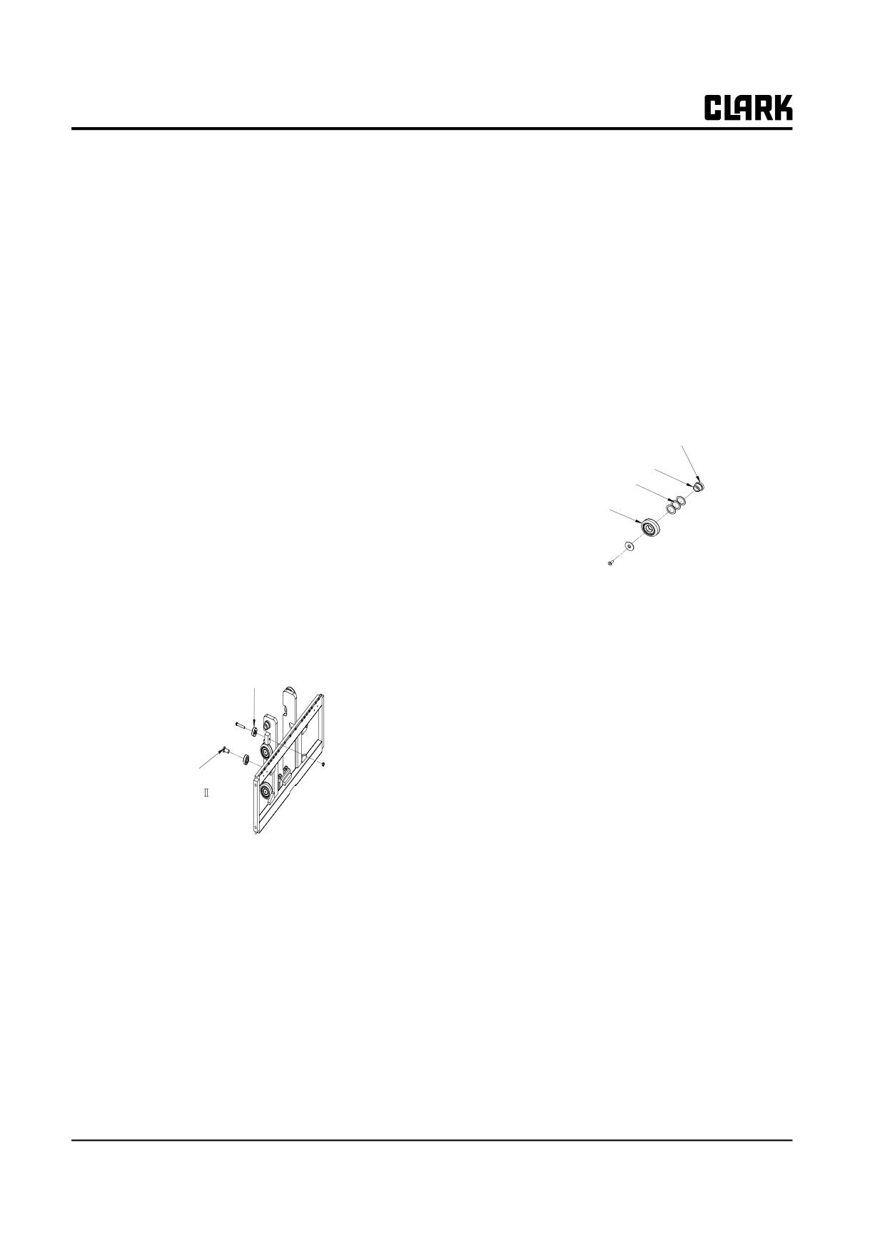
Group 34, Uprights
• Tie bar areas should be free of foreign objects and
NOTE
debris. The roller area of the rail should be cleaned
Some grease will purge from the bearings in
every 500-1000 hours in a normal application.
the first 100-200 hours of operation. This is
- In applications where excessive amounts of
not necessarily a sign of a failed roller bear-
contaminants settle in the rail channels, clean-
ing seal.
ing may be required on 50-250 hour intervals.
- If excessive contamination exists, the rollers
The external thrust rollers are not adjustable. The internal
should be exposed and the bearing seal areas
thrust roller adjusts using a locking cam on the mounting
cleaned thoroughly.
cap screw. See Section 4 for roller replacement and inter-
See Section 4 for carriage roller and upright
nal thrust roller adjustment procedures.
roller removal and installation.
Carriage and Upright Main Load Rollers
Inspect the carriage and upright main load rollers for bro-
Carriage and Upright Rollers
ken, loose, or rough bearings. Defective rollers should be
replaced.
Carriage Thrust Rollers
Shoulder
The carriage uses two types of thrust rollers.
Roller shaft
• The internal thrust roller is found on both standard
shims
and TSUs. The carriage internal thrust rollers are
Bearing outer race
located on the lift bracket and run on the inside
web of the inner rail. The internal thrust roller is
intended to carry a portion of the carriage lateral
load.
• The second type of carriage thrust roller is an
Indications of broken or damaged rollers include:
external thrust roller. The external thrust roller runs
along the outside flange of the inner rail to control
• Part of all of roller bearing missing
lateral load on the carriage. External thrust rollers
• Bearing outer race loose
are found on STD, Hi-Lo CL III and TSUs.
• Scraping noise from the upright
Internal thrust roller
• Scraping of carriage fork bar on inner rail (carriage
rollers)
• Upright rail sections scraping together (upright
rollers)
• Upright misstaging
External thrust roller
(not in 2.0/2.5 ton STD
• Excessive looseness of the rail section or carriage
and Hi-Lo CL )
demonstrated by the following load test.
NOTE
Both types of thrust rollers should be checked for smooth
Some grease will purge from the bearings in
rotation, seal integrity, radial bearing tightness, and a tight
the first 100-200 hours of operation. This is
cap screw. A roller should turn smoothly without sticking
not necessarily a sign of a failed roller bear-
and be grit free. Replace the roller if any defect is found.
ing seal.
External thrust roller cap screws have a locking patch to
Load Test
prevent the cap screw from backing out. Repeated
A load test helps you to determine the amount of clear-
removal will deteriorate the ability of the patch to hold the
ance between the moving upright parts. The upright
cap screw. If the cap screw is backing out without holding,
requires some lateral movement between the interlocking
a new cap screw is recommended. The cap screw can also
rails and the carriage. But, too much or too little clearance
be cleaned and set using thread locking compound Loctite
can be the cause of binding and uneven operation.
271 (Clark Part 1802302). The internal thrust rollers use a
jam nut to ensure that the bearing remains secure.
34-3-6 • Upright Inspection
SM 765, Nov ’06
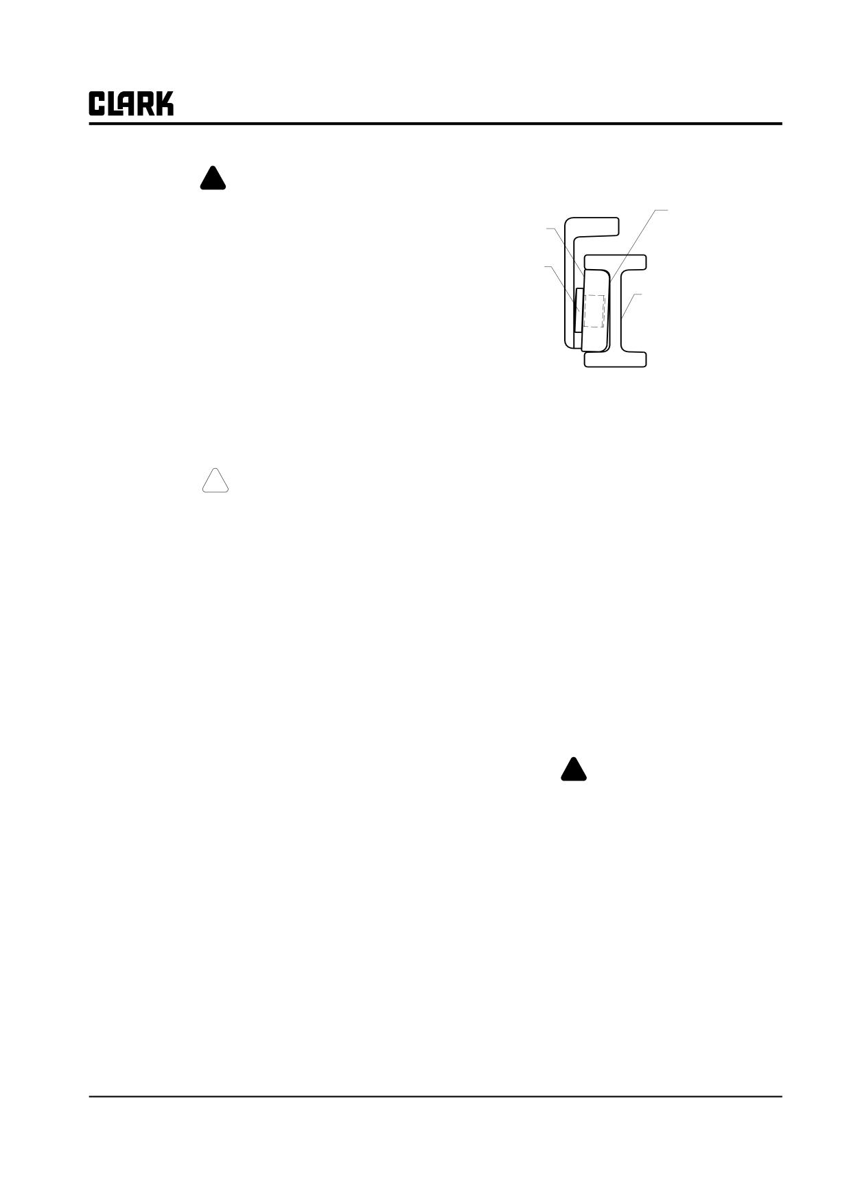
Group 34, Uprights
manufacturing tolerances and wear in the upright rail sec-
! WARNING
tions.
An upright or carriage can move unexpect-
Side Clearance
edly during service procedures causing
Roller
severe injury:
Do not walk or stand under raised forks.
Roller Shaft
Keep clear of load and carriage when making
and shoulder
any check or adjustment.
Rail Web
Keep your arms and fingers away from mov-
ing parts of the upright.
Do not reach through open areas of the
upright.
Failure to follow these warnings can result in
serious injury.
Signs of loose shimming include:
1. Excessive lateral (side-to-side) movement in the
1.
Place a capacity load on the forks and secure it to the
upright rail sections
carriage.
2. Excessive lateral shift in the upright at, or near, full
maximum fork height (MFH)
! CAUTION
3. Irregular roller patterns on the rail.
Test load must be stacked stably, not extend
beyond the pallet, and be secured on the pal-
Signs of over shimming include:
let. Operate the truck only from within the
1. Mis-staging or hanging up of the upright
operator’s compartment.
2. Excessive wear in the rail web
2.
Tilt the upright back slightly and raise the upright to
3. Premature bearing failure.
its maximum extension several times. Note the
Perform the following roll pattern check and the load test
smoothness of operation, the carriage play, and play
if the need for roller shimming is suspected. See Section 4
between the rails.
for detailed clearance measurement procedures.
3.
Move the load 102 mm (4 in) off center on the forks
Roll Patterns
and resecure it to the carriage.
Impressions made by rollers on upright rails are called roll
4.
Raise the upright to its maximum extension and
patterns. Roll patterns can provide indication of the need
lower the load to the floor several times.
for upright or carriage adjustment.
5.
Repeat the step, moving the load 102 mm (4 in) off
center to the other side.
!
WARNING
6.
Raise the upright to its maximum extension and
Keep clear of load and carriage when making
lower the load to the floor several times.
any checks or adjustments.
Carefully observe the smoothness of operation, particu-
larly in carriage play, and play between the rails. If any
1. Elevate the carriage about 4 feet (1.3 m).
unusual movement, staging, or noise occurs during the
2. Apply a light, thin layer of grease to the roller con-
test, correct the problem before returning the truck to ser-
tact area.
vice. Continue with the following roller shimming checks
if too much play is evident in the carriage and rails in the
3. Lower the forks and pick up a capacity load. Raise
load test. The troubleshooting guide may also help to
and lower the upright several times.
identify specific problems with upright operation.
4. Back out from the load and raise the carriage.
Roller Side-Clearance
Compare the impressions of the rollers on each side of the
The carriage and upright rollers are shimmed between the
upright rails. The impressions should look the same on
inner race and the roller shaft shoulder to maintain mini-
both sides. Look for signs of metal scoring or gouging
mal clearance between the side of the roller and the web
which can indicate excessive pressure caused by damaged
of the adjacent rail. Shim adjustments help accommodate
or misadjusted rollers.
SM 765, Nov ’06
Upright Inspection • 34-3-7
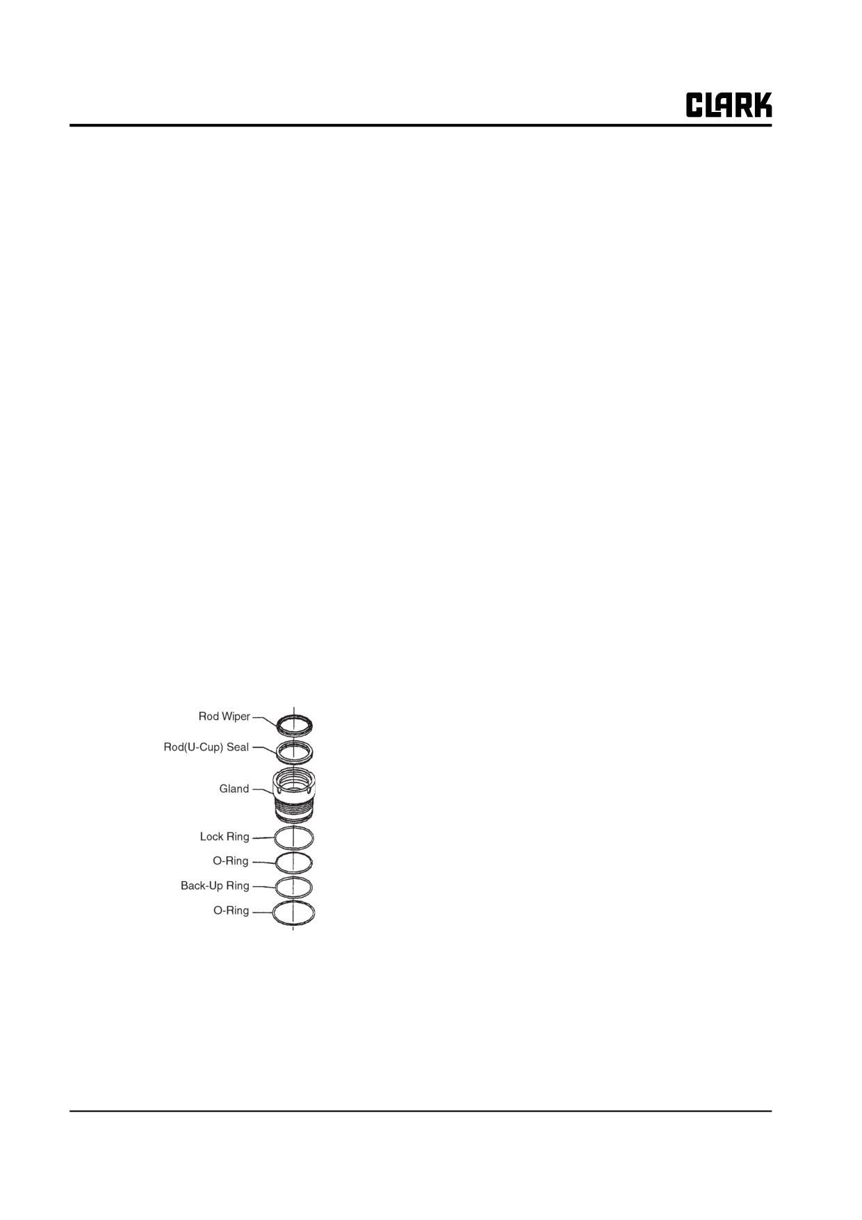
Group 34, Uprights
Carriage rollers, including side-thrust rollers, and all
NOTE
upright rollers can be checked by examining roll patterns.
The seals are installed with lubricant and a
If irregular impressions result from the checks, perform
trace amount will be in the gland/tube inter-
the “Lift Cylinder Shimming Check” and the “Load Test”
face area.
to further diagnose problems.
4. After cleaning the top of the gland and the barrel,
See Section 4 for procedures to measure clearances and
cycle the upright 5-10 times. If a ring of oil forms to
adjust carriage or upright rollers.
run 3 mm (0.125 in) down the rod, the cylinder must
be overhauled or replaced.
Cylinders
Internal Leakage on Primary Cylinder
Use the Drift Test, presented under “Hydraulic Checks”
To check for internal leakage on the primary cylinder:
below, for additional diagnosis of cylinder condition. See
1. Lift the upright to maximum height then lower forks
Section 5 for cylinder repair.
completely.
External Leakage (All Cylinders)
2. Cycle the upright 5-10 times through the first 2/3
To check for external leakage on the primary cylinder:
length of the primary stroke and lower forks com-
1. Clean the top of the gland and rod to remove any
pletely.
buildup of debris.
3. Slowly lift the carriage 305-610 mm (1-2 ft) into the
2. Check rod surface for defects or unusual wear.
secondary lift stage then lift to full extension.
• Nicks, burrs, or other sharp defects can cause dam-
4. If the carriage does not lift to full height, the problem
age to the seal and will lead to leaks. The rod
is likely an internal leak and the cylinder should be
should be repaired or replaced.
overhauled.
• For piston-type cylinders, small blunt defects in the
5. If the carriage does lift to full height, but you still
top and midsection of the rod can be tolerated in
suspect an internal leak, repeat the procedure with a
this cylinder design. The high pressure sealing is
40-70% capacity load.
over the last several inches of stroke. This type of
defect is acceptable if leakage is not evident.
NOTE
3. Check for external leakage from the cylinder barrel,
The primary cylinder normally has approxi-
gland O-rings and backup ring, and the rod seal.
mately 100 ml (3.4 oz) of hydraulic fluid on
the rod side of the piston as a pre-charge.
Use the Drift Test, presented under “Hydraulic Checks”
below, for additional diagnosis of cylinder condition. See
Section 5 for cylinder repair.
Internal Leakage on Piston-Type Lift and Secondary
Cylinders
To check for internal leakage in Standard lift and TSU
secondary cylinders:
1. Lift the upright to MFH then lower forks completely.
2. Cycle the upright 5-10 times through the first 2/3
length of the lift cylinder stroke and lower forks com-
pletely.
• The gland O-rings and backup ring are near-zero
3. Lift the upright to full MFH.
leakage seals. If, after cleaning the gland and tube,
Watch for the lift cylinder to increase lift speed. If you see
oil accumulates to form a run, the O-rings and
an increase in lift speed, one or both of the lift cylinders
backup ring should be replaced (see Section 5).
have an internal leak and requires overhaul.
• External leakage from the barrel requires replace-
ment of the barrel.
34-3-8 • Upright Inspection
SM 765, Nov ’06
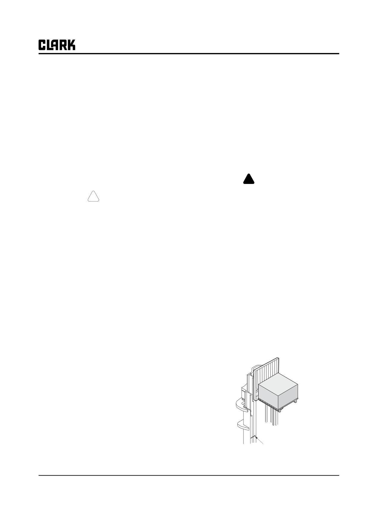
Group 34, Uprights
If the upright does not increase lifting speed, but you still
a. Hoses or tubes with scrapes or kinks should be
suspect an internal leak, repeat the procedure with a
replaced.
capacity load. If the upright does not extend to full MFH,
b. Hoses with outer cover wear exposing the rein-
the problem is likely an internal leak and the cylinder
forcement braiding should be replaced.
should be overhauled.
Lift Cylinder Shimming
Upright Drift
The lift cylinders on both standard uprights, Hi-Lo and
Drift tests check cylinder, main valve, and hydraulic cir-
TSUs bottom out at the end of the stroke to limit upright
cuit integrity under load pressures. A load is held elevated
extension. The upright has dual lift cylinders and the cyl-
for an extended period to determine how much the upright
inders’ extension length must be equal. If not, “racking,”
“drifts” (moves) over a specified time period. A tilt cylin-
or side-to-side shifting, results. Rod extension length is
der drift test appears in Group 32, Section 2, “Tilt Cylin-
made equal by using shims under the rod end of the cylin-
der Checks and Adjustments.”
der. To determine if shimming of the cylinders is required
to prevent racking, perform the following operational
check:
!
WARNING
An upright or carriage can move unexpect-
! CAUTION
edly during service procedures causing
severe injury:
Make sure truck is parked on level surface
Do not walk or stand under raised forks.
with parking brake applied and wheels
Keep clear of load and carriage when making
chocked; make sure overhead clearance is
any check or adjustment.
adequate to extend upright to its full height.
Keep your arms and fingers away from mov-
ing parts of the upright.
1. Center the forks or attachments on the upright.
Do not reach through open areas of the
2. Check for equal chain tension.
upright.
Failure to follow these warnings can result in
3. Raise the upright from the retracted position to full
serious injury.
lift height. Note the point when the lift cylinders
reach the end of their stroke.
1.
Raise upright with the rated capacity and carriage to
• If the upright shifts right or left noticeably, shim-
its full extension and lower to a point halfway down
ming is required.
from full extension with the upright substantially ver-
• Repeat the check three times before adding shims.
tical.
NOTE
2.
Shut off the truck. Apply the parking brake and
Offset or unbalanced loads and off-center
chock the wheels.
attachments can cause the upright to shift
3.
With a pencil or chalk, make a mark across the rails
even with proper lift cylinder shimming.
on one side of the upright.
See Section 5 for lift cylinder shimming procedure. Rack-
ing adjustments for tilt cylinders appear in Group 32, Sec-
tion 2, “Tilt Cylinder Checks and Adjustments.”
Hydraulic Plumbing
Use the Lift Cylinder Shimming Check, the Load Test,
and the following Drift Test to check the performance of
the hydraulic system.
1. Check all fittings for leakage. Disassemble fittings
and inspect the seals. Replace seals as required. See
Group 40 for hydraulic fitting tightening procedures.
Mark upright
rails here
2. Check all hoses and tubes for wear and damage.
SM 765, Nov ’06
Upright Inspection • 34-3-9
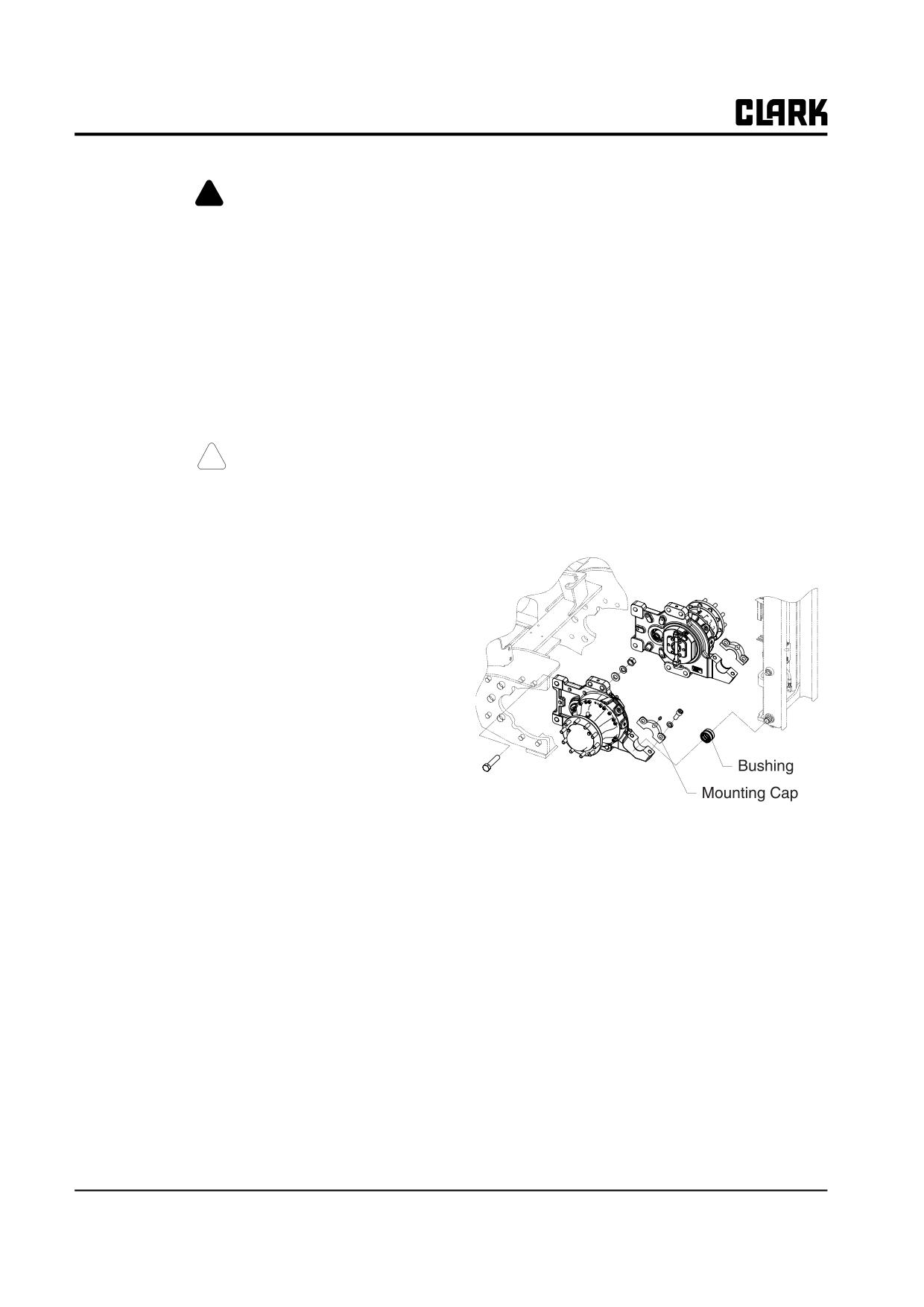
Group 34, Uprights
Consider rebuilding the cylinders if the first two remedies
! WARNING
in this list are not successful. See Section 5 for removal,
Keep clear of load and carriage when making
overhaul, and replacement procedures for primary and
any checks or adjustments. Do not use the
secondary cylinders.
upright to climb; use an approved platform.
Upright Mounting Check
4. Wait ten minutes and recheck the mark. Measure and
write down the distance the marks on the inner and
To check the Upright mounting:
intermediate rails have drifted from the mark on the
1. Check for missing, broken, bent, or loose trunnion
outer rail.
cap fasteners. Replace any damaged parts.
5. If the rated load drift 50 mm (2 in) or more in the ten
2. Lift the upright 305-610 mm (1-2 ft) and tilt the
minutes, read and follow the procedures presented in
upright fully forward.
“Drift Causes and Remedies.”
3. Check for Bushing or cap wear by inserting a feeler
gauge between the upright mounting cap and the
! CAUTION
axle-mounting bearing surface.
Test load must be stacked stably, not extend
beyond the pallet, and be secured on the pal-
let.
Drift Causes and Remedies
If drift of 50 mm (2 in) or more is evident under the rated
load, consider the following causes and remedies:
• The main hydraulic valve is misadjusted, worn, or
defective. Fluid is leaking past the valve and caus-
ing the upright cylinders to drift. See Group 30 for
hydraulic valve troubleshooting and service.
• Upright hydraulic circuit hoses or fittings are leak-
ing. Check the circuit components and repair as
necessary.
• Cylinder piston seals are worn, damaged, or defec-
tive allowing fluid past the piston causing drift.
• Primary cylinder or piston-type lift or secondary
cylinders have a check valve that allows oil to flow
back to the rod side of the cylinder. This check
valve may be clogged or defective. Inspect the
check valve for proper sealing and operation.
• The gap should not exceed 0.75 mm (0.03 in).
• If the gap exceeds 0.75 mm (0.03 in) the bearing or
cap may need replacement.
See Section 8, “Upright Removal and Replacement,” for
procedures to remove and replace the bushing.
34-3-10 • Upright Inspection
SM 765, Nov ’06
Group 34, Uprights
Section 4
Carriage and Upright Roller Clearance Checks and Shim
Adjustments
IMPORTANT
!
WARNING
Before removing any component for over-
haul, make sure the correct repair parts and/
Use an approved safety platform to reach the
or kits are available.
upper areas of the upright. Never use the
upright as a ladder.
! WARNING
Introduction
An upright or carriage can move unexpect-
edly:
Standard and Hi-Lo upright assemblies have two lift roller
• Do not walk or stand under raised forks
sets mounted on the rails, three lift roller sets mounted on
• Kee clear of load and carriage when mak-
the carriage, and two internal and external (except 2.0/2.5
ing any check or adjustment
ton STD) thrust roller set mounted on the carriage.
• Keep your arms and fingers away from
External thrust roller set used more than 3.0ton trucks.
moving parts of the upright.
• Block the carriage or upright when work-
The triple-stage upright assemblies have four lift roller
ing with the components in a raised posi-
sets mounted on the rails, three lift roller sets mounted on
tion.
the carriage, and two thrust roller sets (“internal” and
• Do not reach through open areas of the
“external”) mounted on the carriage. (see the “Roller Side
upright.
Clearance Chart” on next page.)
• Never attempt to move or align the rails
Each carriage and upright lift roller is nested within its
by hand. Use a prybar.
adjacent rail set. The front “face” of the lift roller handles
Failure to follow these warnings can result in
front-to-back friction and play between the nesting seg-
serious injury.
ments of the upright assembly, the side “face” of the roller
radius handles side-to-side friction and play. The rollers
SM 765, Nov ’06
Carriage and Upright Roller Clearance Checks and Shim Adjustments • 34-4-1
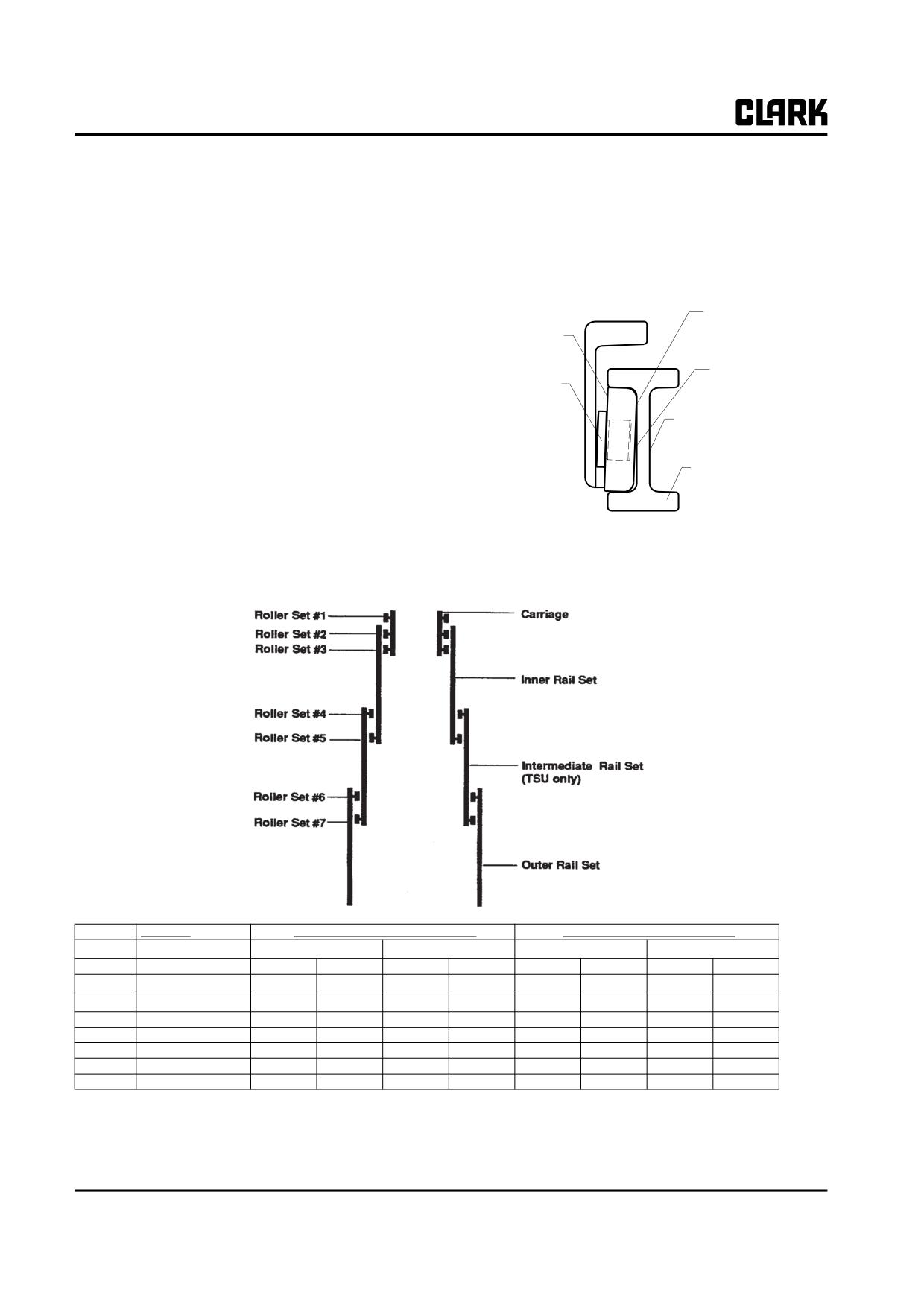
Group 34, Uprights
are canted (tilted) to allow the side face to bear properly
tainty that the clearance is excessive, you perform the
on the web.
checks given below.
Rail flange wear can cause excess play between the lift
To correct excessive lift roller side clearance, you add
rollers and the rail flange. The only way to correct this is
shims as described later in this Section. To correct internal
to install oversize rollers-only one size of which is avail-
thrust roller clearance, you adjust thrust roller position as
able. If oversize rollers were fitted previously, the only
described later in this Section.
remedy for excessive front-to-back play is to replace the
Gap
rail set. (carriage middle rollers are always standard-size
Lift Roller
rollers; see “Oversize Rollers” later in this Section for
details on roller replacement.)
Side Face
Shoulder
Of Clearance
The gap between the roller “side” and the web of adjacent
rail set affects the side-to-side motion of the upright-
Rail Web
which should be as small as possible without causing the
sliding segments to bind. The same is true of the internal
thrust rollers.
Rail Flange
You check the performance effect of the lift roller side
clearance and internal thrust roller clearance by means of
the load test described in Section 3. To evaluate with cer-
Roller Side Clearance Chart
Roller Side Clearance Chart
Web Area
Gap at Mimimumm Span of Rail Set
Gap at Maximum Span of Rail Set
Roller Set#
Forming Gap
Targeta
Allowedb
Targeta
Allowedb
(mm)
(in)
(mm)
(in)
(mm)
(in)
(mm)
(in)
#1
0.5-1.5
0.02-0.06
0.05-1.25
0.02-0.05
d
d
2.25
0-0.09
Front, Inner railc
#2
Front, Inner rail
0-0.75
0-0.03
0-0.06
d
d
2.25
0-0.09
0-1.5e
#3
Back, Inner rail
0-0.75
0-0.03
0-1.0
0-0.04
d
d
2.25
0-0.09
#4
Back, Inner rail
0-0.75
0-0.03
0-1.0
0-0.04
d
d
2.25
0-0.09
#5
Back, Intermd rail
0-0.75
0-0.03
0-1.0
0-0.04
d
d
2.25
0-0.09
#6
Back, Intermd rail
0-0.75
0-0.03
0-1.0
0-0.04
d
d
2.25
0-0.09
#7
Back, Outer rail
0-0.75
0-0.03
0-1.0
0-0.04
d
d
2.25
0-0.09
a. Target is the desired gap after reshimming the roller set.
d. Ideal is same as final measured gap at minimum width point of rail set.
b. Allowed is the acceptable gap when checking roller set.
e. Measured at top of inner rail.
c. Internal side thrust rollers should extend 0.25-0.50mm(0.01-0.02 in)
beyond #1 rollers.
34-4-2 • Carriage and Upright Roller Clearance Checks and Shim Adjustments
SM 765, Nov ’06
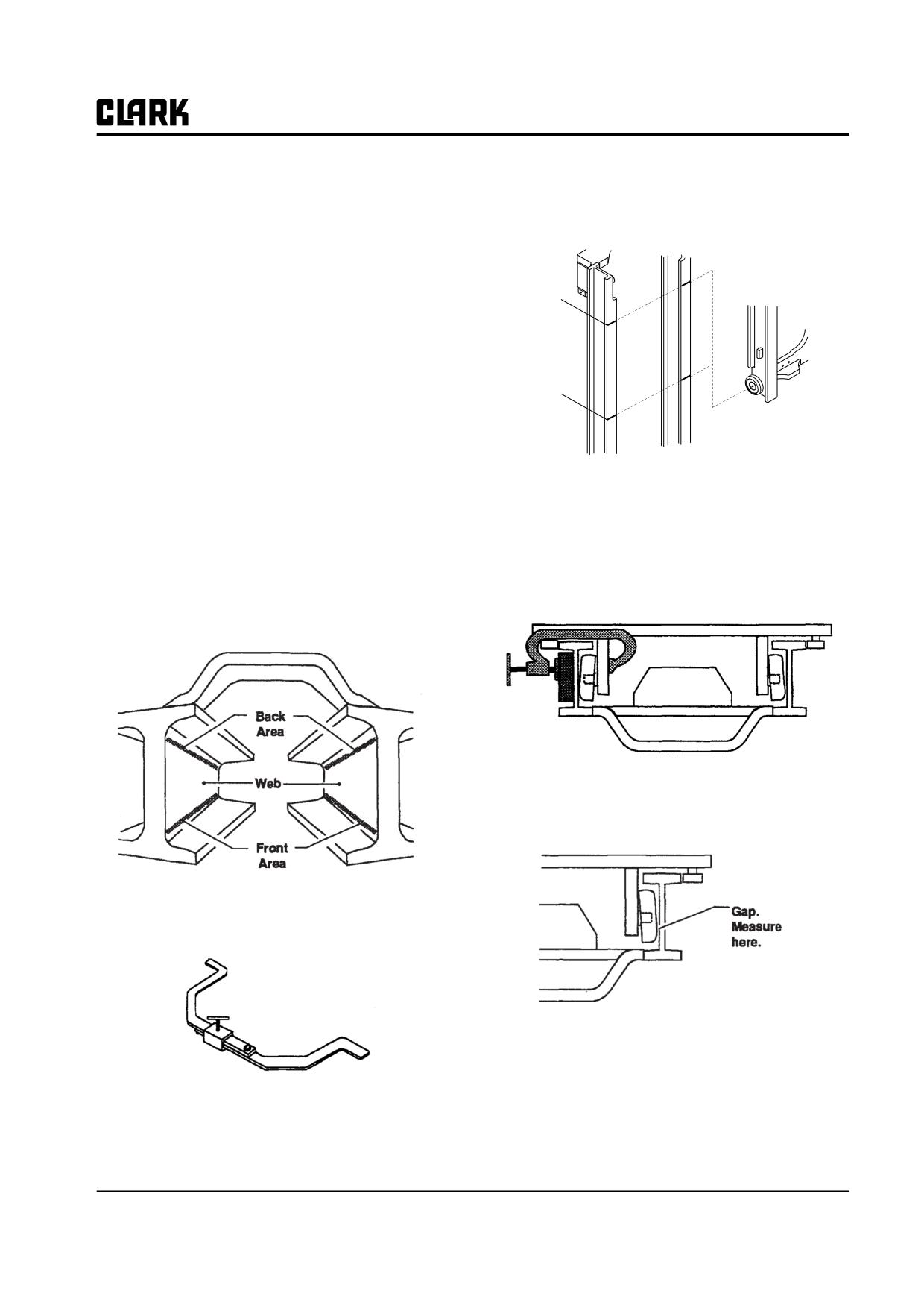
Group 34, Uprights
2. Position the carriage or rails so that the roller set you
Roller Side Clearance Checks
want to check is at the mark for the narrowest span
The same basic procedure is used for checking all the lift
on the adjacent nesting rail set.
rollers. That general procedure is given in the subsection
directly below. Special instructions for specific rollers fol-
low that subsection. Follow those directions (in the sub-
section called “Directions for Checking Specific Rollers”)
Narrowest
and you will be directed to general and specific informa-
span
tion you need.
General Roller Side Clearance Checking
Widest
Procedure
span
For each roller set, you need to measure the gap between
the outside face of a roller and its adjacent nesting rail. In
general, the lift roller side clearance check procedure is as
Example of Aligning Roller Set with Widest and
follows:
Narrowest Spans Marked on Adjacent Rail Set.
Rail sets are shown separated for clarity.
1. With the spanner tool, find and mark the narrowest
and widest spans in each rail set at the roller-contact
3. Clamp the rails together opposite the roller you
areas in the rail webs:
intend to check. Use wooden shim blocks to protect
the rails. Place clamp as close to roller as possible.
• Inner Rail Set-Mark narrowest and widest spans
Torque clamp to 25 N⋅m (20 ft-lb).
for both the front and back web areas.
• Outer and Intermediate Rail Sets-Mark narrowest
and widest spans for the back web area only.
4. Measure the gap with a feeler gauge. Make sure
roller is tight against its shoulder. Write down the
result.
Web Areas on Typical Rail Set
5. Repeats steps 2 through 4 for the widest span marked
on the rail set.
Spanner Tool. Clark Part #180109
SM 765, Nov ’06
Carriage and Upright Roller Clearance Checks and Shim Adjustments • 34-4-3
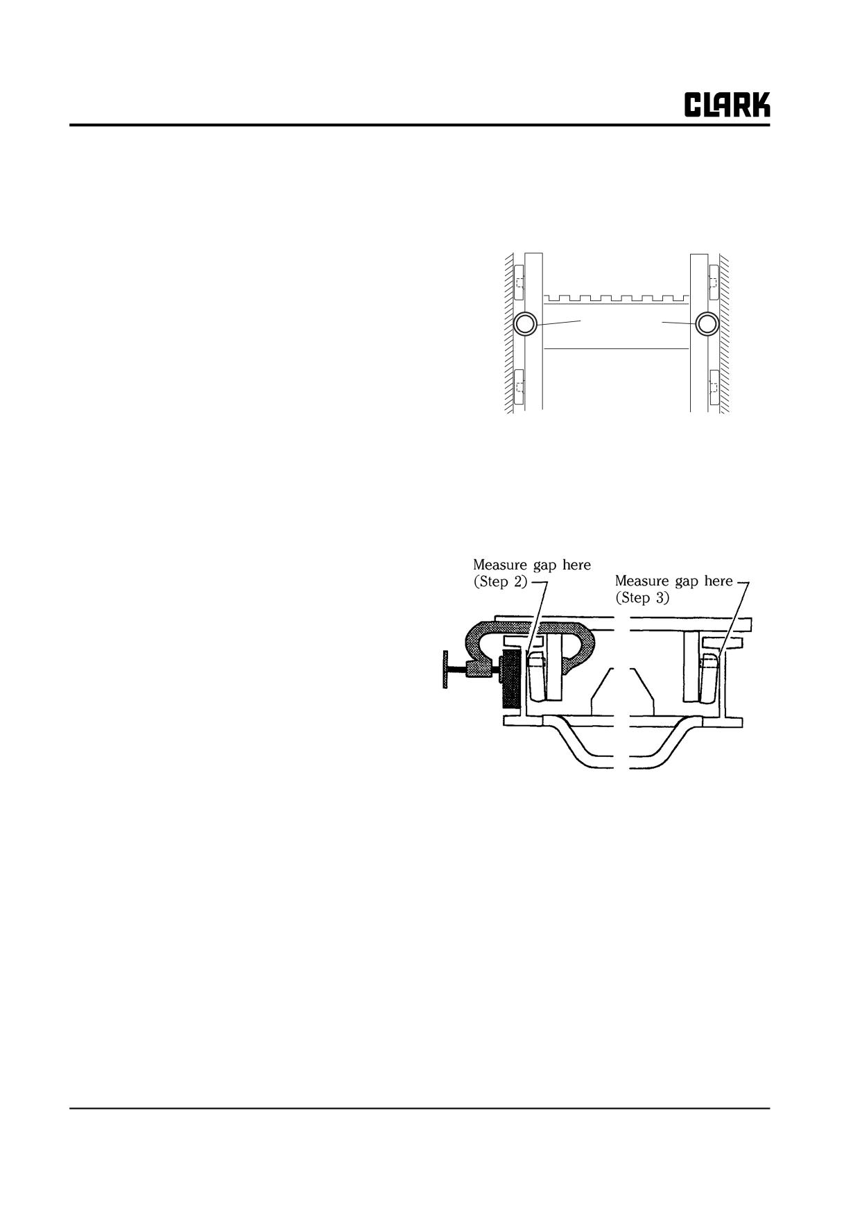
Group 34, Uprights
6. If the clearance at the widest rail set span is more
Top Carriage Rollers and Internal Thrust Rollers
than 2.25 mm (0.09 in), the roller set needs shim-
The internal thrust rollers are nearly perpendicular to the
ming.
top carriage lift rollers and contact the same flange area as
If the clearance at the narrowest rail set span is more
the carriage rollers. The top carriage lift rollers and the
than 1.0 mm (0.04 in), the roller set should be
internal thrust rollers should be checked together.
shimmed; however, it is OK for the middle carriage
roller gap to be up to 1.5 mm (0.06 in).
7. Repeat entire procedure for each roller set, following
the instructions in “Directions for Checking Specific
Interral Thrust
Rollers” below.
Rollers
Rollers
Directions for Checking Specific Rollers
Use these directions to supplement the general procedures
given above.
1.
Move the top carriage lift roller to the narrowest span
Carriage Rollers
on the inner rails set.
Bottom Carriage Rollers
2.
Clamp rail to one side as in general procedures.
Follow the general procedure above.
Check clearance of lift roller on clamped side. Locate
Middle Carriage Rollers
the clamp between the thrust roller and the bottom
roller of the carriage.
The middle rollers are difficult to access and require the
following special procedures.
1. Raise the carriage until the middle rollers are at the
top of the inner rails.
2. Measure roller side clearance at the top of the inner
rails. Note measurement here:
_____________________
If gap is less than 1.5 mm (0.06 in), shimming is not
required.
If gap is more than 1.5 mm (0.06 in), check clearance
at narrowest span by comparison with the top of the
rail set as follows:
a. With spanner tool, measure span of inner rail set
at top of the front web area. Note measurement
The internal thrust roller should contact the web and
here:
_____________________
cause the lift roller to stand off from the web by .01
b. With spanner tool, measure span of inner rail set
to 1 mm (0.001-0.03 in). If the gap is outside this
at narrowest span of front web area. Note mea-
range, the internal thrust roller must be adjusted as
surement here:
_____________________
explained later in this Section under “Internal Thrust
c. Subtract measurement in step b from measure-
Roller Adjustment.”
ment in step a, Write result here:
b-a=
_____________________
3.
Check clearance on lift roller opposite clamped side
If the calculated gap is less than or equal to the
as in the general procedures. If clearance is greater
gap measured in step 2, the roller set does not
than 1.25 mm (0.05 in), the roller set should be
require shimming. Otherwise, the roller set
shimmed.
should be shimmed.
4.
Move clamp to opposite side and check clearance on
clamped side as in step 2 directly above. Gap should
be 0.01-1.0 mm (0.001-0.03 in).
5.
Move the top carriage lift roller to the widest span on
the inner rail set and check clearance as in general
procedures.
34-4-4 • Carriage and Upright Roller Clearance Checks and Shim Adjustments
SM 765, Nov ’06
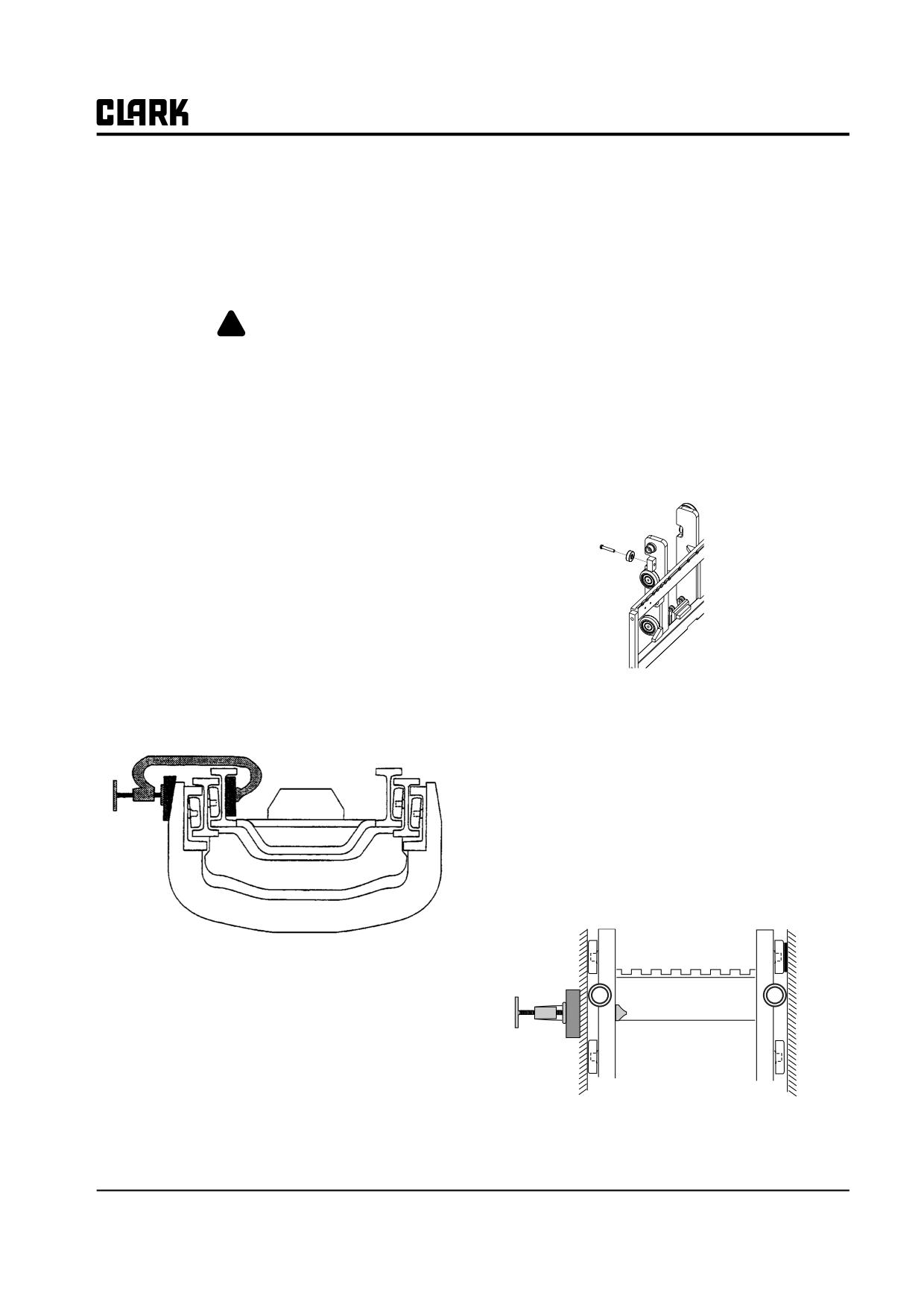
Group 34, Uprights
Upright Rollers
Internal Thrust Roller Adjustment
1.
Remove the carriage as described in Section 7 of this
The internal thrust rollers should be adjusted to extend 0-
Group.
0.75 mm (0.03 in) into the top carriage roller side clear-
2.
Fully extend the upright making sure carriage hoses
ance. Carriage roller side clearance should be within toler-
and chains are secured out of the way to prevent
ances before you adjust the thrust rollers.
damage.
NOTE
Carriage must be replaced on upright before
! WARNING
adjusting internal thrust rollers. See Section
An upright or carriage can move unexpect-
8 for carriage replacement procedures.
edly:
• Do not walk or stand under raised forks
1.
Lift the carriage to the top of the inner rail.
• Keep clear of load and carriage when
making any check or adjustment
2.
Loosen the jam nut on the back of the thrust roller
• Keep your arms and fingers away from
cap screw and then loosen the cap screw. Rotate the
moving parts of the upright.
bearing to pivot toward the carriage and away from
• Do not reach through open areas of the
the rail.
upright.
• Never attempt to move or align the rails
by hand. Use a prybar.
• Use an approved safety platform to reach
the upper areas of the upright. Never use
the upright as a ladder.
Failure to follow these warnings can result in
serious injury.
3.
Follow the “General Roller Side Clearance Checking
Procedure” given earlier in this Section.
3.
Lower the carriage to a convenient height to do the
The clamping procedure is as illustrated below.
adjustment.
4.
Clamp the carriage between the top and middle car-
riage roller.
• Use a shim block under the clamp on the outside of
the channel rail.
• Torque on the clamp should not exceed 25 N⋅m (20
ft-lb).
5.
Insert a 0.5 mm (0.02 in) temporary shim between
the top carriage roller and the rail web on the side
opposite the clamp. If a 0.5 mm (0.02 in) shim will
not fit, insert a 0.25 mm (0.01 in) shim.
SM 765, Nov ’06
Carriage and Upright Roller Clearance Checks and Shim Adjustments • 34-4-5
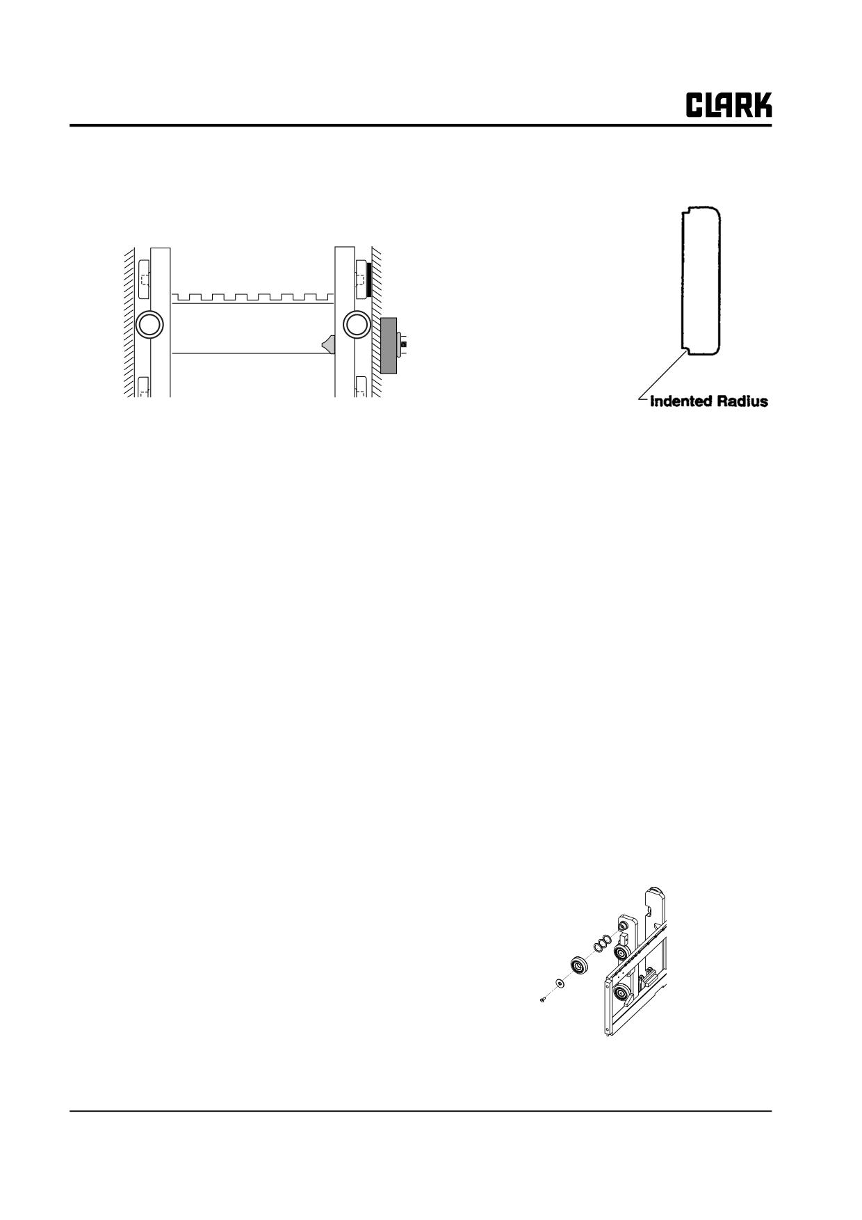
Group 34, Uprights
6.
Move the clamp to the shimmed side and clamp the
Oversize Rollers
rollers against the shim and the rail web by position-
ing the clamp between the top and middle carriage
At the time of roller shimming,
rollers.
you may want to replace the lift
rollers with oversize rollers to
counter rail flange wear as
detected by inspection and the
load test. Because there is only
one size of oversize rollers, you
can install them only if they were
not installed previously.
Identify oversize rollers as fol-
lows: If a roller is oversize, it has
an indented radius in the outer
7.
Cam the thrust roller on the shimmed side against the
edge of its mounting side, as shown below.
rail clockwise and tighten the cap screws firmly.
NOTE
Lift Roller Shimming
Make sure the roller does not rotate with the
cap screw when tightening.
You need to shim lift rollers if the roller side clearance
checks indicated that clearance was excessive at either the
8.
Insert a 0.5 mm (0.02 in) shim in the opposite roller.
narrowest or widest span of the roller set’s adjacent rail
If a 0.5 mm (0.02 in) shim will not fit, insert a 0.25
set.
mm (0.01 in) shim.
Your objective in shimming is to add only enough shims
9.
Loosen the clamp and remove the shim.
to bring the clearances at both the widest and narrowest
spans into tolerances. In practice, you achieve this by
10.
Reposition the clamp on the opposite side and draw
shimming to obtain the smallest possible clearance at the
the roller against the shim and rail web.
narrowest span of the rail set.
11.
Cam the thrust roller on this shimmed side toward the
rail clockwise and tighten the cap screws firmly.
Carriage Roller Shimming
NOTE
Using the measurement you recorded in previously in the
Make sure the roller does not rotate with the
“Roller Side Clearance Checks,” determine the number of
cap screw when tightening.
shims required to reduce the carriage roller clearance at
the narrowest span on the inner rail to 0-0.75 mm (0-0.03
12.
Loosen the clamp and remove the shim.
in):
13.
Use a crow’s foot to torque the cap screws 70-80 N⋅m
1. Remove the carriage as described in Section 8, “Fork
(51.5-59.2 ft-lb).
and Carriage Removal and Replacement.”
NOTE
2. Remove the rollers (note the number of shims
If a crow’s foot is not available, the carriage
already on the roller shafts, if any).
can be raised to the top of the inner rail and a
socket used to tighten to the correct torque.
14.
Position the carriage to access the jam nut on the
back side of the cap screw and torque to 70-80 N⋅m
(51.5-59.2 ft-lb).
• Clean and inspect roller bearings, shims, and
shafts.
34-4-6 • Carriage and Upright Roller Clearance Checks and Shim Adjustments
SM 765, Nov ’06
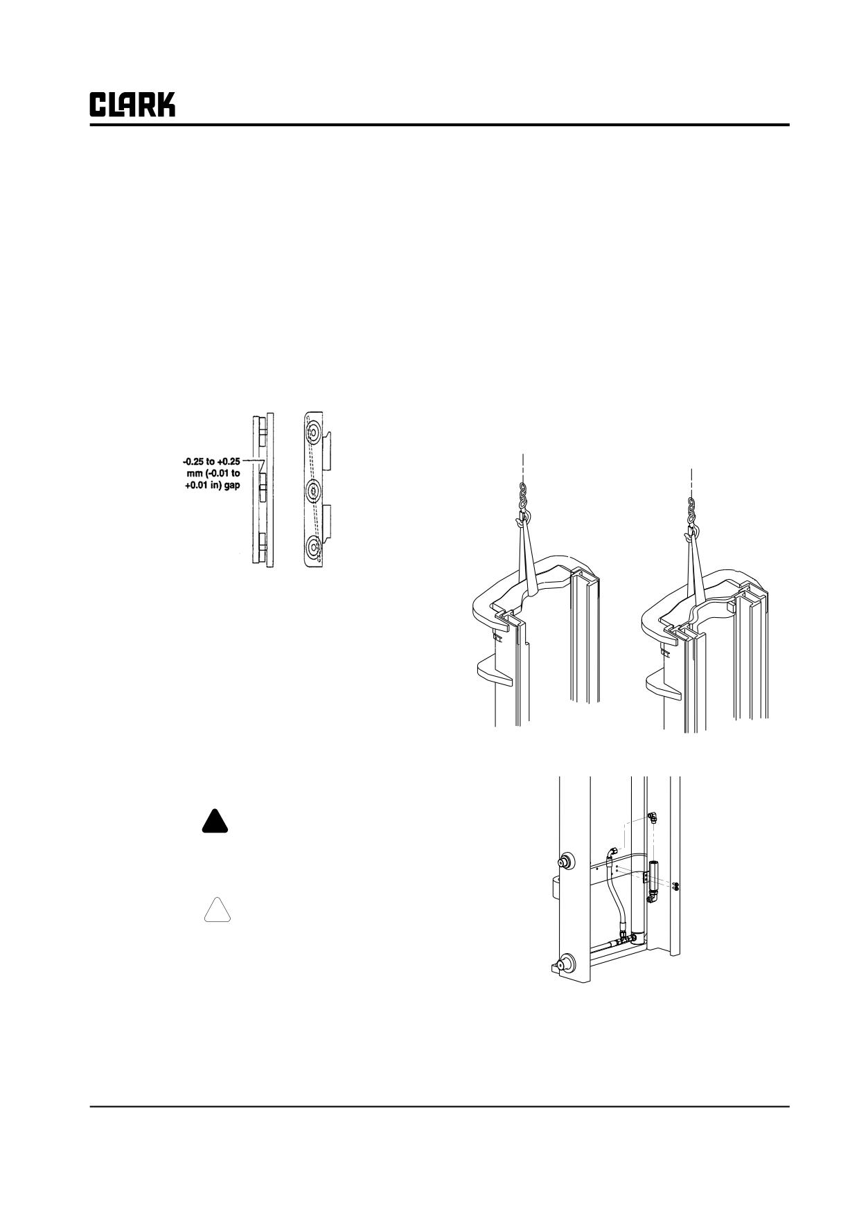
Group 34, Uprights
• Replace any defective parts.
Upright Roller Removal
3. Add shims to the top and bottom rollers as deter-
1. After the carriage has been removed, lower the
mined in the previous steps.
upright rails until both of the secondary (final) lift
cylinders are completely collapsed.
• Install shims with the same number on each side.
2. Jack the truck and block under the frame so that the
• When an odd number of shims is required, always
bottom of the upright is approximately 254 mm (10
place the odd shim on the same side on all roller
in) off the floor. See “Lifting, Jacking, and Blocking”
sets.
in Group SA for safe procedures.
4. Use a straight bar to determine the number of shims
3. Set the parking brake and block the steer wheels.
to add to the middle roller shaft as shown in the fol-
lowing illustration. This shimming may be asymmet-
4. Tilt the upright to as near vertical as possible.
ric, meaning the numbers of shims do not have to
5. Using a hoist and lifting strap of adequate capacities,
match those of the top and bottom rollers.
connect the lifting strap to the inner rail on standard
and Hi-LO uprights or intermediate rails on triple-
stage uprights. Lift hoist to remove slack from the
strap.
5. Reinstall all bearings; torque top roller fasteners to
40-45 N⋅m (30-33 in-lb).
Carriage internal thrust rollers must be adjusted after the
carriage is shimmed. Adjust as described previously.
Upright Roller Shimming
Use the following procedures to remove, shim, and
replace rollers. Use the preceding checks to determine the
6. Disconnect the flow control valve manifold from the
number of shims required to reduce the roller clearances
upright bracket.
to 0.75 mm (0.03 in) or less.
! WARNING
Use an approved safety platform. Never use
the upright as a ladder.
! CAUTION
The carriage should be removed for shim-
ming or when any service is performed on the
upright. See Section 8, for removal and
replacement procedures.
SM 765, Nov ’06
Carriage and Upright Roller Clearance Checks and Shim Adjustments • 34-4-7
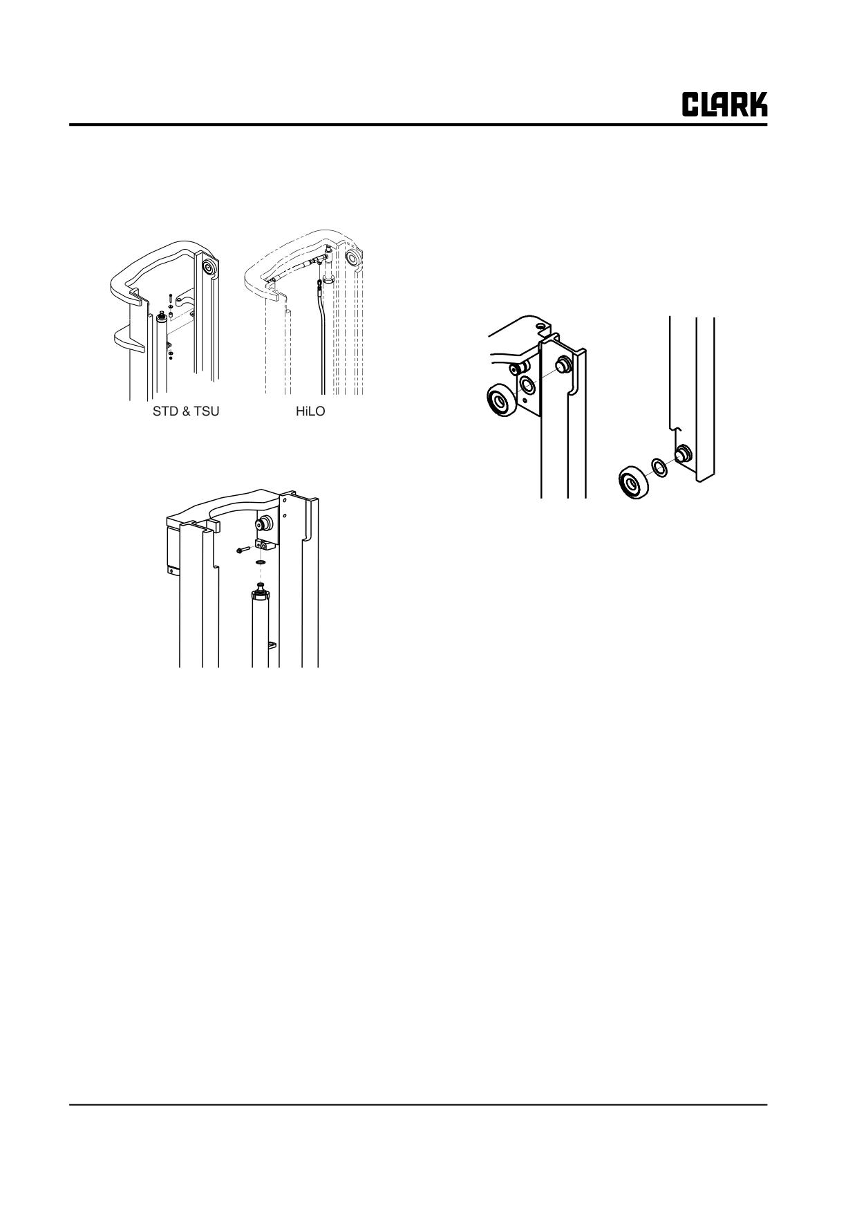
Group 34, Uprights
7. Disconnect the cylinder guide bolts.
Roller Removal, Shimming, and Replacement
In Hi-Lo upright, disconnect the secondary cylinder
To add shims to, or replace the rollers:
hose.
1. Use a puller to remove the rollers from the posts. Or,
gently pry the rollers off the posts. Pry at different
points around the bearing to work it off. Do not dam-
age the bearing seals on the backside of the roller.
8. Secure the cylinder to prevent its falling and discon-
nect the cylinder rod retaining bolts.
2. Inspect all roller components when removed:
a. Clean and inspect the rollers, shims, and roller
shafts.
b. Bearings should be in good condition and allow
the roller to spin smoothly with a true rotation.
c. Clean rail sections and add lubricant if necessary.
d. Replace any worn or damaged component.
3. If the clearance check indicated an even number of
shims needed, split the number evenly between the
NOTE
rollers on either side of the upright.
For 4-hose adapters, you must disconnect the
hose sheave and bracket. This is not neces-
4. If the clearance check indicated an odd number of
sary for 2-hose adapters.
shims needed, keep the odd number to the same side
on all rails of the upright. If three shims are needed,
9. Move the sheave with the hoses and any other con-
for example, add one to the rollers on the left side.
nected components out of the way.
Add the other two on the rollers on the right side.
10. Disconnect the rail cylinders by raising the rails to
5. Reposition the rollers onto the roller shaft and use a
free the cylinder rod ends from the tie bar. Tilt the
plastic or hard-rubber mallet to gently tap the roller.
cylinders inward and secure out of the way of the tie
Seat the roller evenly by continuing to tap gently
bars.
until it is fully seated and snug against the added
shims.
11. Lower the assembly completely to expose the rollers.
The lower roller set of the inner rail and upper roller set of
the outer rail on standard and triple-stage uprights are now
exposed for shim adjustment.
34-4-8 • Carriage and Upright Roller Clearance Checks and Shim Adjustments
SM 765, Nov ’06
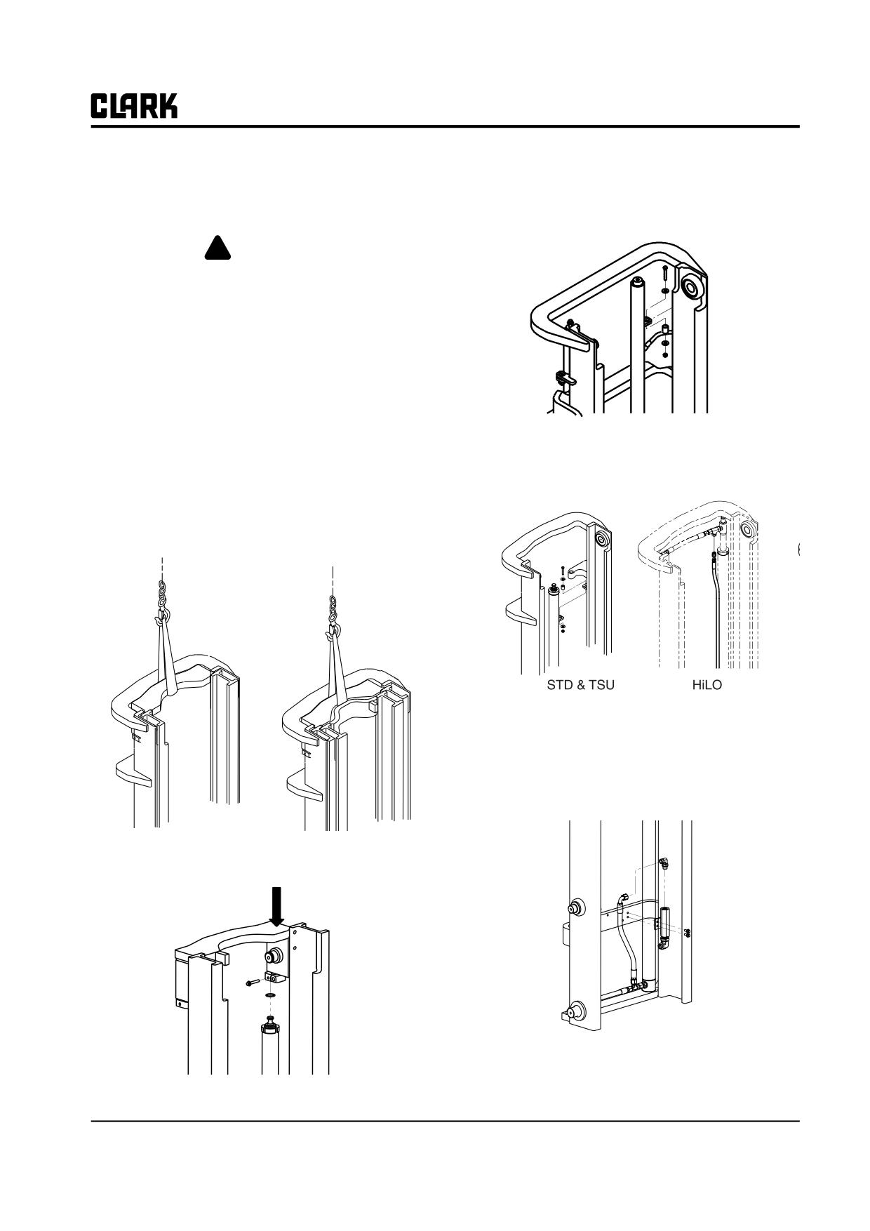
Group 34, Uprights
Upright Reassembly
3. Reconnect the cylinder guide bolts. Do not tighten
until inner and/or intermediate rails are in the fully
The following steps detail the procedures for reassem-
lowered position. Torque guide bolts nuts to 20-25
bling the upright.
N⋅m (14.8-18.5 ft-lb).
! WARNING
The upright can move unexpectedly:
• Keep your arms and fingers away from
moving parts of the upright.
• Do not reach through open areas of the
upright.
• Never attempt to move or align the rails
by hand. Use a prybar.
Failure to follow these warnings can result in
4. Reconnect the cylinder rod retaining bolts. Torque
serious injury.
rod retaining bolts to 20-25 N⋅m (14.8-18.5 ft-lb).
In Hi-Lo upright, Reconnect the Secondary cylinder
1. Connect the lifting strap to the inner rail on standard
hose.
and Hi-Lo uprights or intermediate rails on triple-
stage uprights and raise the rails just high enough to
clear the lift cylinders. Use a prybar to guide the rails
and allow the rollers to reenter the rail channel.
5. Replace the 4-hose sheave and bracket assembly onto
the upright. Torque nuts to 20-25 N⋅m (14.8-18.5 ft-
lb).
6. Reconnect the load lowering flow valve to the
upright bracket. Torque nuts to 20-25 N⋅m (14.8-18.5
ft-lb).
2. Reposition the rail cylinders and slowly and carefully
lower the rails to seat the rod end into the mounting.
SM 765, Nov ’06
Carriage and Upright Roller Clearance Checks and Shim Adjustments • 34-4-9
Group 34, Uprights
7. Jack up the truck only enough to remove the blocking
Overshimming
and slowly lower the truck so that its full weight is on
the floor.
Use these steps to check for overshimming:
8. Replace the carriage and forks.
1. With the forks removed, lift the upright to maximum
fork height.
9. Test the upright lift and tilt functions; make sure all
upright components work correctly and smoothly.
2. Slowly lower the upright.
Check for overshimming as described in the next
• The carriage should not bind or hang up at any
subsection. Repeat the load test to make sure the
point along the rails.
upright works correctly under load. When you are
• If the carriage binds or hangs up, and the rails are
sure all components are operating correctly, perform
not clogged with grease or debris, the carriage
the chain adjustment checks in Section 3 before
requires reshimming. See “Troubleshooting” for
returning the truck to service.
other mis-staging problems.
34-4-10 • Carriage and Upright Roller Clearance Checks and Shim Adjustments
SM 765, Nov ’06
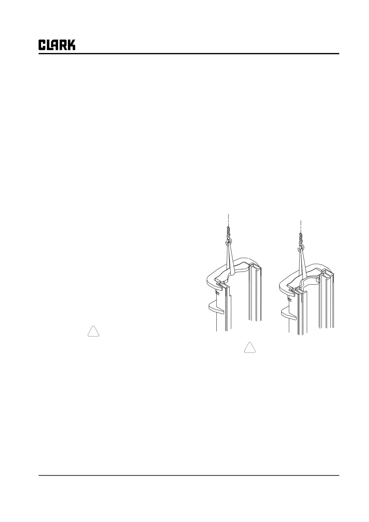
Group 34, Uprights
Section 5
Cylinder Removal, Shimming, Overhaul, and Replacement
Cylinder Types
Lift Cylinder Shimming Procedure
Standard uprights use two lift cylinders. Hi-Lo and Triple
To shim the lift cylinders to correct unequal cylinder
stage uprights use three cylinders, a primary (center-
stroke:
mounted) cylinder, and two secondary cylinders. All pri-
1. Fully lower upright until both lift cylinders are col-
mary cylinders used on Hi-Lo and triple-stage uprights
lapsed.
(TSUs) are piston cylinders. The lift and secondary cylin-
ders used on standard, Hi-Lo uprights and TSUs are either
2. Attach a hoisting strap to the tie bar of the inner rail
piston or ram cylinders.
or intermediate rail tie bar of TSUs.
IMPORTANT
Before removing any component for over-
haul, make sure the correct repair parts,
seals, and gasket sets are available.
Upright
Upright
Type
Number
Cylinder Type
<GEX20-30>
Standard pneu V2324 Piston-Type Lift Cylinder
TSU
pneu M2324 Piston-Type Secondary Cylin-
der
Hi-Lo
pneu H2317 Piston-Type Secondary Cylin-
der
! CAUTION
To remove, or partially remove, the cylinders
from the upright for shimming or overhaul,
!
CAUTION
start with the truck in a safe position:
Make sure hoisting equipment is of adequate
capacity and in good working order.
• Ignition off
• Parking brake applied
• Directional lever in neutral
• Forks lowered completely
• Wheels blocked.
SM 765, Nov ’06
Cylinder Removal, Shimming, Overhaul, and Replacement • 34-5-1
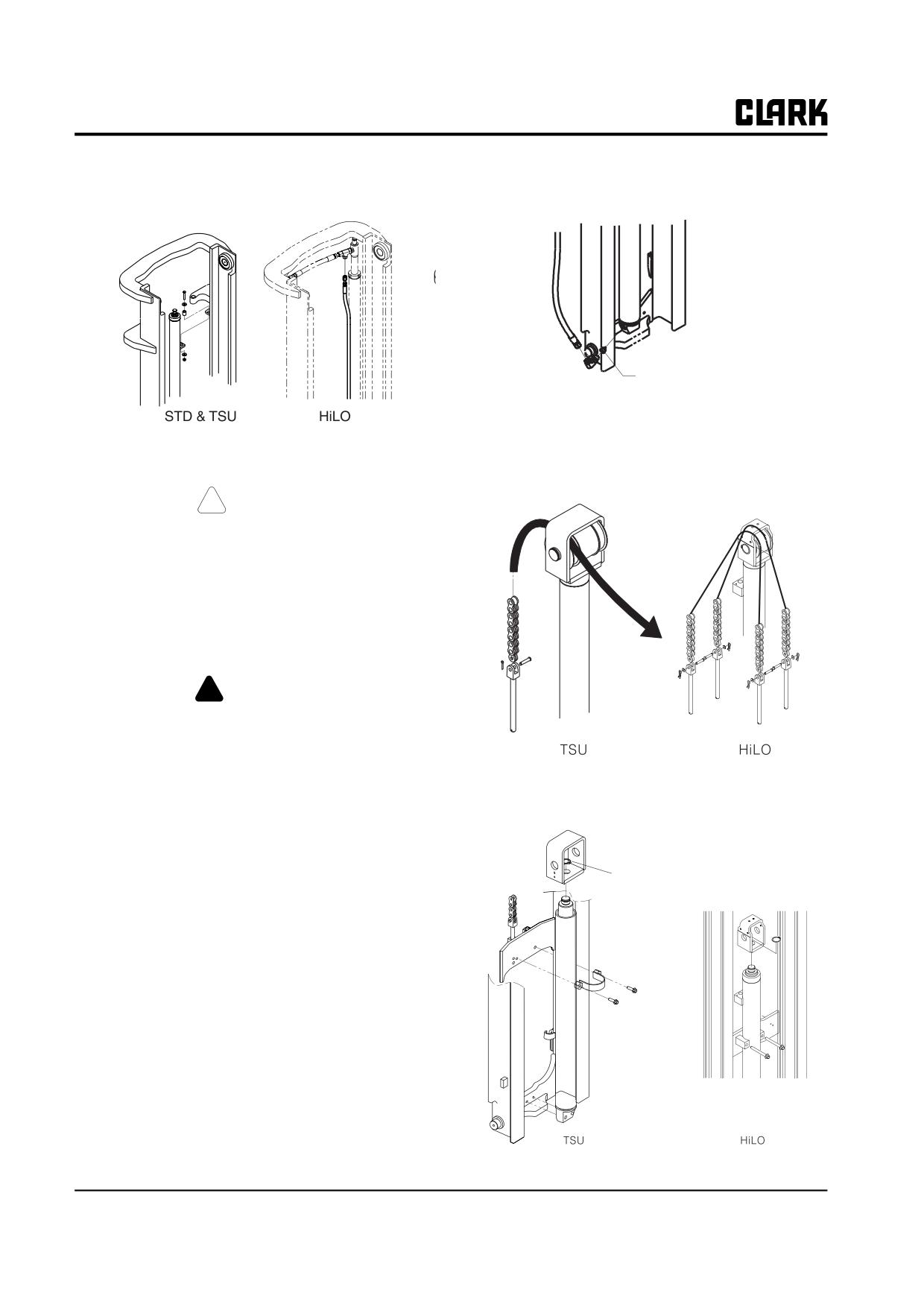
Group 34, Uprights
3. Remove the cylinder rod retaining bolt.
2. Disconnect and cap the hydraulic line at the base of
In Hi-Lo Upright, Remove the Cylinder Hose.
the cylinder.
Load Lowering
Flow Valve
3. Remove and discard cotter pins from chain anchor
4. Slowly lift the inner (or intermediate) rails off the top
bolt pins on the cylinder.
of the cylinder to expose the cylinder rod top.
4. Remove the pins, draw the chain through the sheave,
and drape the chain over the carriage.
! CAUTION
Block rail in up position.
5. Insert shim(s) over rod end of cylinder with the
shorter stroke to compensate for unequal stroke
length.
6. Slowly lower the inner or intermediate rail back onto
the rod ends.
! WARNING
Do not try to maneuver the cylinder or rails
with your hands. Use a prybar.
7. Replace cylinder rod retaining bolt to secure rod end
5. Remove the snap ring holding the chain sheave (and
into inner or intermediate rail mounting hole. Torque
hose bracket, if equipped) on the rod end and move
the cylinder rod retaining bolts to 20-25 N⋅m (14.8-
assembly off top of rod.
18.5 ft-lb).
8. Repeat the racking test and adjustment until no rack-
Snap Ring
ing is evident during upright lift extension.
9. Check all upright functions before returning the truck
to service.
Primary Cylinder Removal and
Replacement (Hi-Lo & TSU)
Remove the primary cylinder for replacement only. Cylin-
der can be overhauled without removing it from the
upright. See “Cylinder Overhaul” for procedures.
1. Make sure the cylinder is completely collapsed and
pressure is released.
34-5-2 • Cylinder Removal, Shimming, Overhaul, and Replacement
SM 765, Nov ’06
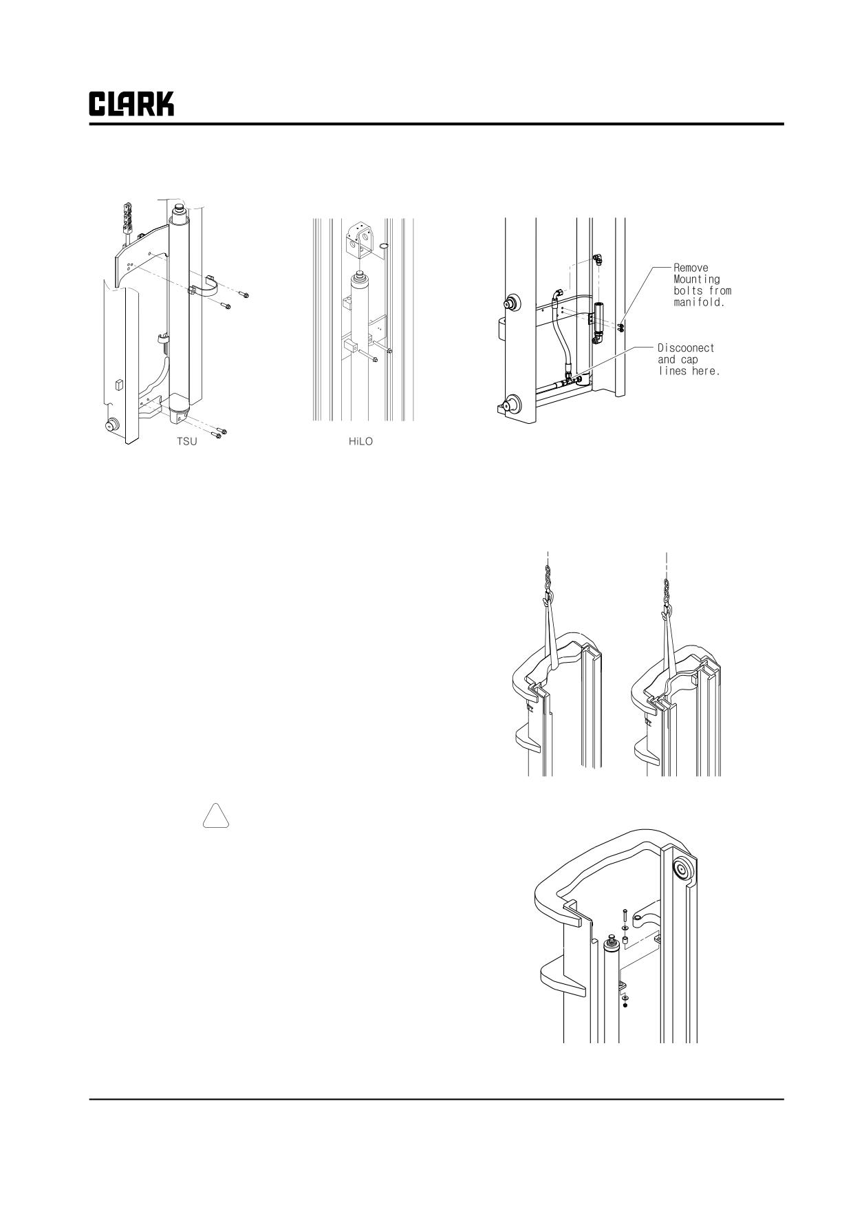
Group 34, Uprights
6. Disconnect cylinder mounting bolts and cylinder
4. Disconnect and cap the hydraulic line from the base
base mounting bolts.
of each cylinder. Remove the mounting bolts from
the manifold block.
Use these steps in reverse to replace the cylinder. Check
5. Lower the carriage
Group 40 for hydraulic fitting tightening procedures. If
6. Using a hoist and lifting strap of adequate capacities,
complete cylinder was torque hydraulic line bracket to 40-
connect the lifting strap to the inner rail on standard
45 N⋅m (30-33 ft-lb).
& Hi-Lo uprights and inner and intermediate rails on
triple-stage uprights.
Lift and Secondary Cylinder
Removal and Replacement
Only piston-type lift and secondary cylinders must be
removed from the upright for overhaul. The cylinder gland
and rod can be removed for overhaul while leaving the
cylinder tube mounted on the truck.
1. Make sure the cylinders are completely collapsed and
pressure is released.
2. Tilt the upright to as near vertical as possible.
3. Using a hoist and lifting strap of adequate capacities,
lift the carriage to access the hydraulic lines at the
base of the cylinders.
7. Disconnect the cylinder guide bolts.
! CAUTION
Make sure hoisting equipment is of adequate
capacity and in good working order.
SM 765, Nov ’06
Cylinder Removal, Shimming, Overhaul, and Replacement • 34-5-3
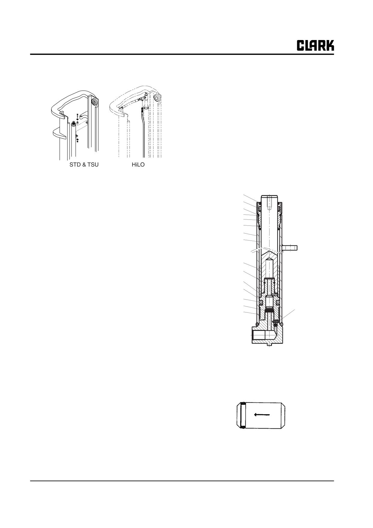
Group 34, Uprights
8. Disconnect the cylinder rod retaining bolts.
1.
Clean the rod-end and gland thoroughly to prevent
In Hi-Lo upright, Remove the cylinder hoses.
contamination from falling into the cylinder during
disassembly.
2.
With a blunt punch or chisel, bend the lock ring out
of the locking grooves of the gland.
3.
Use a spanner wrench to remove the gland. Reuse the
lock ring if undamaged.
4.
Carefully lift the rod out of the cylinder and place in
a clean area.
5.
Inspect the tube and tube end for damage and cover
the cylinder tube end to prevent contamination.
9. Remove the cylinders by raising the inner rail (and
6.
Remove all rings and seals from the piston and the
intermediate rail on the triple stage upright) to free
gland.
the cylinder rod ends from the tie bar.
Rod Wiper
10. Remove any shims and note number and location.
Rod Seal
O-Ring
11. Lift the cylinders off the base mount.
Back-Up Ring
Gland
Use these steps in reverse to replace the cylinders. Torque
O-Ring
the cylinder rod retaining bolts to 20-25 N⋅m (14.8-18.5
Tube
ft-lb). Torque the cylinder guide bolt nuts to 30-35 N⋅m
Rod
(22.2-25.6 ft-lb). Check Group 40 for hydraulic fitting
tightening procedures.
Spacer
Retaining Ring
Cylinder Overhaul
Check Valve
Use these steps to overhaul the primary and lift and sec-
Piston
ondary (TSU) cylinders.
Cylinder Seal
NOTE
Snap Ring
Pin
Wear Ring
During overhaul, set rod or cylinder on a
work bench with adequate support for safe
and convenient disassembly. Two sets of 4x4
in (100x100 mm) “V”-notched blocks are
helpful; one set for the cylinder barrel and
one set for the piston rod. The blocks prevent
7.
For piston-type cylinders:
nicks and scratches from harming the piston
a. Remove the check valve from the piston for
or rod.
inspection and cleaning by removing the snap
ring from the piston bore.
Cylinder Disassembly
• To overhaul the primary cylinder, it is not neces-
sary to remove the cylinder from the upright.
Instead, free the rod end of the cylinder as
explained in “Cylinder Removal.”
• To overhaul piston-type cylinders, you should
remove the cylinders from the upright as explained
in “Cylinder Removal.” The cylinders have seals
Check Valve. Arrow shows direction of flow
on the piston, and the rods must be removed for
b. Use a blunt hook to pop the check valve out.
seal replacement.
34-5-4 • Cylinder Removal, Shimming, Overhaul, and Replacement
SM 765, Nov ’06
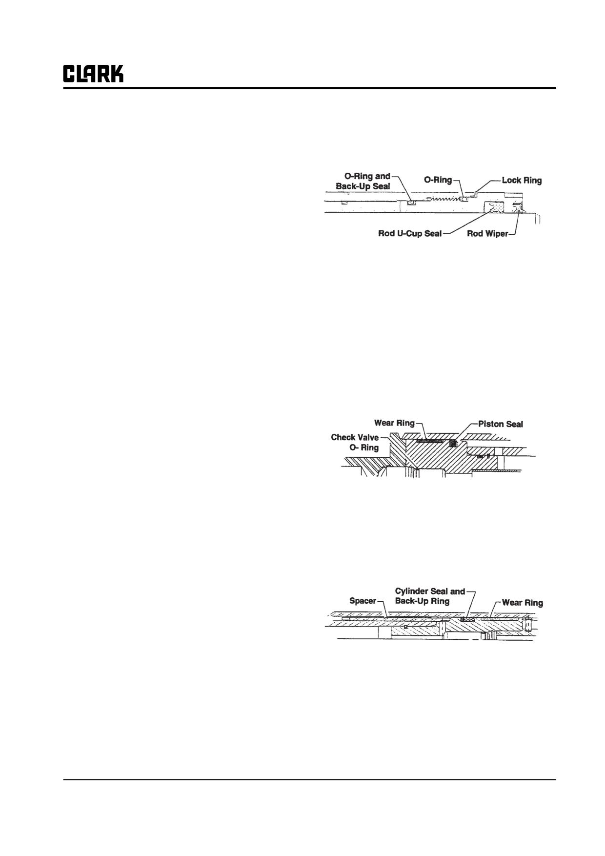
Group 34, Uprights
IMPORTANT
2.
Replace the U-cup seal (groove toward bottom of
Use extreme care that you do not make nicks
cylinder), rod wiper, and O-ring and back-up seals on
and burrs on the interior surface area of the
the gland.
cap or cylinder or the piston.
Parts Inspection and Service
1. Clean all parts completely in a suitable solvent. Dry
all parts with a soft clean cloth.
2. Inspect cylinder barrel and bore for cracks, pining,
scoring, or other irregularities that may require
replacement of the barrel.
NOTE
3. Inspect the piston and rod for nicks, scratches, scor-
ing, or other defects that may demand new parts.
O-rings should be carefully installed to elimi-
nate cuts or twisting.
4. Check all gland and piston seal grooves for nicks,
burrs, and scratches that can damage seals during
3.
Replace the piston seals:
reinstallation.
a. Primary cylinder pistons require a piston seal and
5. Inspect and clean the check valves.
wear ring. Install the piston seal from the top of
the rod. Use a ring compressor to compress the
6. Inspect all seals, including the check valve O-ring.
piston seal. This prevents damage to the seal dur-
ing reassembly.
NOTE
Minute imperfections inside the cylinder bar-
rel or on the piston or rod may be improved
for acceptable use by careful honing. How-
ever, removal of material that produces a
notch, groove, or out-of-roundness may cause
excessive leakage during operation and a
shortened life.
7. Use new parts as necessary. Always use the Packing
Kit listed in the parts manual. New kits include all
b. Piston-type lift and secondary cylinder require a
the seals, wiper rings, wear rings and O-rings neces-
cylinder seal, a back-up ring, and a wear ring on
sary for the particular cylinder.
the piston. Install the cylinder seal from the top of
the rod.
Cylinder Reassembly
Take care when installing these parts to make sure that no
parts are damaged.
1. Coat all packing, seals and rings in clean, hydraulic
oil (Clark part number 1800236 qt., 1802155 gal.)
prior to reassembly. Coat the inside of the gland nut
bore with hydraulic oil.
4.
For protection against corrosion, lubricate spacers
(where used) with petroleum-based hydraulic fluid.
Slide the spacer onto the rod.
SM 765, Nov ’06
Cylinder Removal, Shimming, Overhaul, and Replacement • 34-5-5
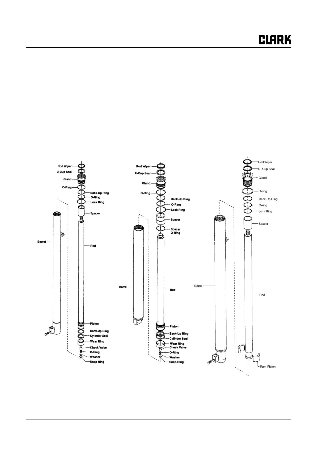
Group 34, Uprights
5. Insert the piston and rod into the cylinder. Be careful
8. Check the assembly by making sure the piston slides
not to scratch or damage the cylinder gland nut
freely in and out of the cylinder.
threads.
9. Tighten the gland nut:
6. For primary cylinders, add 3.4 oz (100 ml) of hydrau-
• On primary cylinders, tighten the gland nut to 135
lic oil into the cylinder on the rod side of the piston.
N⋅m (100 ft-lb).
7. Install the lock ring onto the gland. Lubricate cylin-
• On lift and secondary cylinders, tighten the gland
der threads and screw gland onto cylinder. Be careful
nut to 100 N⋅m (75 ft-lb).
not to damage gland seal. Make sure the gland is
This competes the cylinder repair procedure. Replace the
fully seated on the cylinder barrel. Deform the lock
cylinders as described in “Cylinder Removal and Replace-
ring into slots in the tube and the gland.
ment.” Complete the chain length adjustment in Section 3
for correct carriage and rail position. When all adjust-
ments are completed, return the truck to service.
Hi-lo and Triple-Stage Upright
Typical Piston-Type Standard
Hi-lo Upright Lift and TSU
Upright Lift and TSU
Primary Cylinder
Secondary Cylinder
Secondary Cylinder
34-5-6 • Cylinder Removal, Shimming, Overhaul, and Replacement
SM 765, Nov ’06
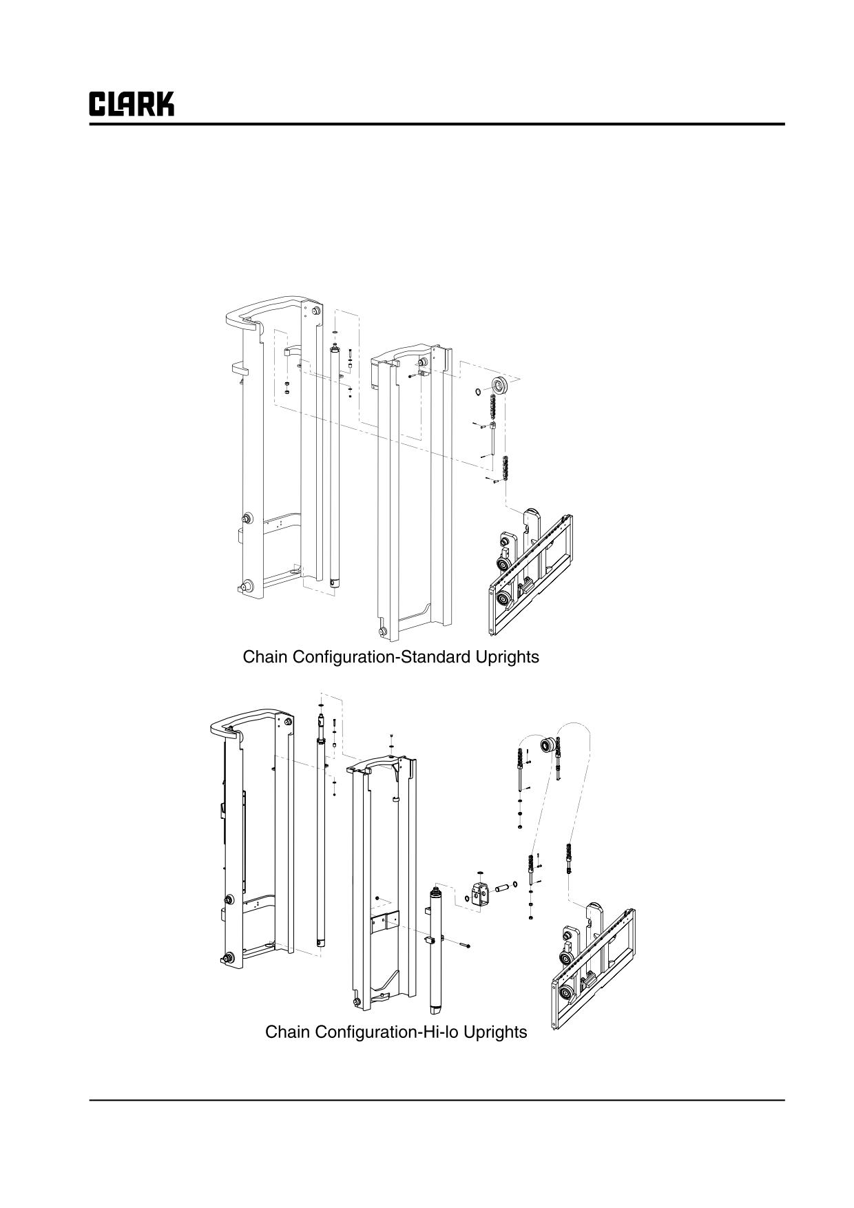
Group 34, Uprights
Section 6
Upright Chain Inspection, Adjustment, and Replacement
SM 765, Nov ’06
Upright Chain Inspection, Adjustment, and Replacement • 34-6-1
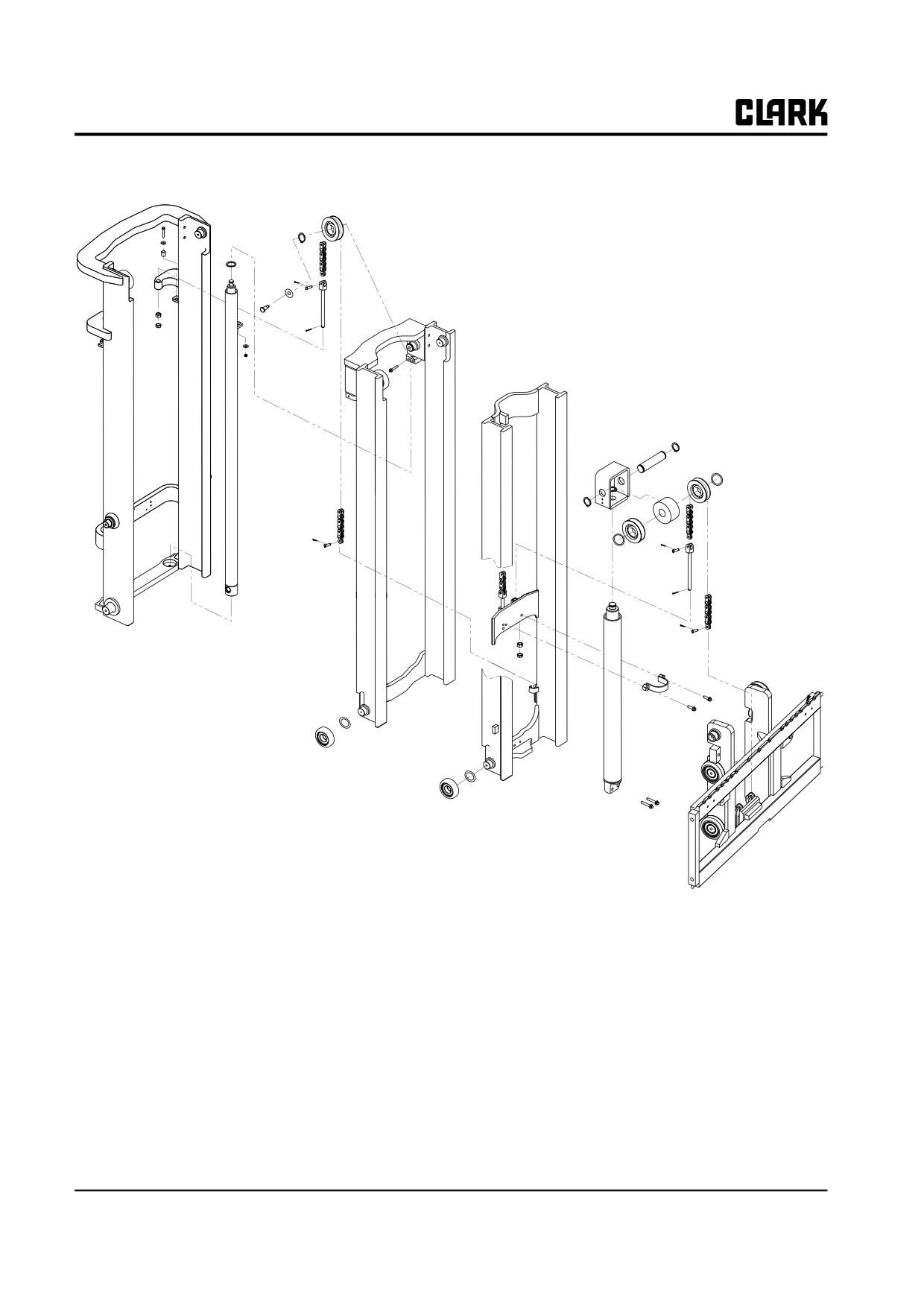
Group 34, Uprights
Chain Configuration-Triple Stage Uprights
34-6-2 • Upright Chain Inspection, Adjustment, and Replacement
SM 765, Nov ’06
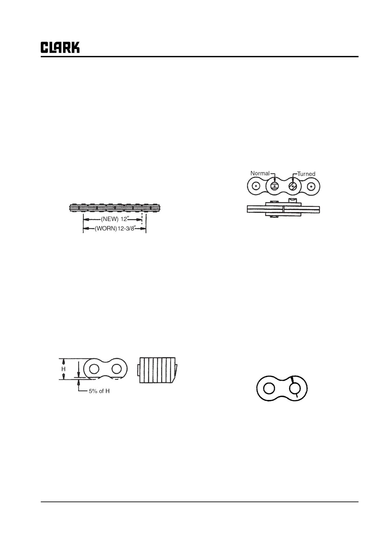
Group 34, Uprights
in this condition, a pin, or series of pins, can begin to twist
Periodic Inspections
out of a chain resulting in failure. The pin head rivets
Each 50-250 hours of operation (more frequently in severe
should be examined to determine if the "VEE" flats are
or extreme environments), chains should be inspected and
still in correct alignment. Chain with rotated/displaced
lubricated. Inspection should focus on the following:
heads or abnormal pin protrusion should be replaced
immediately. Do not attempt to repair the chain by weld-
ing or driving the pin(s) back into the chain. Once the
Elongation
press fit integrity between outside plates and pins has been
When a length of 12.00 inches (305 mm) of new chain has
altered, it cannot be restored. Any wear pattern on the pin
elongated to a length of 12.360 inches (315 mm), it should
heads or the sides of the link plates indicates misalign-
be discarded and replaced. It is important to measure the
ment in the system. This condition damages the chain and
chain in the section that moves over the sheaves because it
increases frictional loading, and should be corrected.
receives the most frequent articulation. Measuring the
chain near its clevis terminals could give an erroneous
reading as it would not have flexed as frequently, if indeed
at all, as nearer the middle of the assembly.
Turned pins and abnormal pin protrusion.
Chains should be replaced when wear exceeds 3% or
Cracked Plates
when 12 inches (305 mm) of chain is stretched 3/8 inch
The chains should periodically be inspected very care-
(10 mm).
fully, front and back as well as side to side, for any evi-
dence of cracked plates. If any one crack is discovered, the
Edge Wear
chain(s) should be replaced. It is important, however, to
determine the causes of the crack before installing new
Check the chain for wear on the link plate edges caused by
chain so the condition does not repeat itself.
running back and forth over the sheave. The maximum
reduction of material should not exceed 5%. This can be
• Fatigue Cracking - Fatigue cracks are a result of
compared to a normal link plate height by measuring a
repeated cyclic loading beyond the chain's endur-
portion of chain that does not run over the sheave. Dis-
ance limit. The magnitude of the load and fre-
torted or battered plates on leaf chain can cause tight
quency of its occurrence are factors which
joints and prevent flexing.
determine when fatigue failure will occur. The
loading can be continuous or intermittent (impulse
load).
Worn contours and worn surfaces on the outside links or
pin heads should not exceed 5% of new link height.
Fatigue cracks generally run from the pin hole toward the
edge of the link plate approximately 90o from the line of
pull.
Turning or Protruding Pins
Fatigue cracks almost always start at the link plate
Highly loaded chain operating with inadequate lubrication
pin hole (point of highest stress) and are perpendic-
can generate abnormal frictional forces between pin and
ular to the chain pitch line. They are often micro-
link plates. In extreme instances, the torque could surpass
scopic in their early stage. Unlike a pure tensile
the press fit force between the pins and the outside plates,
failure, there is no noticeable yielding (stretch) of
resulting in pin rotation. When chain is allowed to operate
the material.
SM 765, Nov ’06
Upright Chain Inspection, Adjustment, and Replacement • 34-6-3
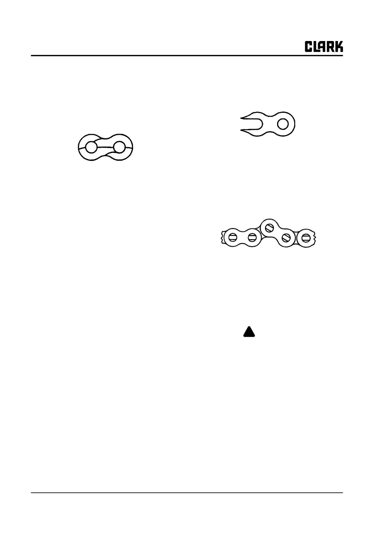
Group 34, Uprights
• Stress - Corrosion Cracking - The outside link
Ultimate Strength Failure
plates, which are heavily press fitted to the pins,
are particularly susceptible to stress corrosion
This type of failure is caused by overloads far in excess of
cracking. Like fatigue cracks, these initiate at the
the design load.
point of highest stress (pin hole) but tend to extend
in an arc-like path between the holes in the pin
plate.
Broken plate caused by overload.
Arc-like cracks in plates are a sign of stress corrosion.
Tight Joints
More than one crack can often appear on a link
All joints in leaf chain should flex freely. Tight joints
plate. In addition to rusting, this condition can be
resist flexure and increase internal friction, thus increasing
caused by exposure to an acidic or caustic medium
chain tension required to lift a given load. Increased ten-
or atmosphere.
sion accelerates wear and fatigue problems.
Stress corrosion is an environmentally assisted fail-
ure. Two conditions must be present: a corrosive
agent and static stress. In the chain, static stress is
present at the pin hole due to the press fit pin. No
cyclic motion is required, and the plates can crack
during idle periods. The reactions of many chemi-
If lubrication does not loosen a tight joint, the chain may
cal agents (such as battery acid fumes) with hard-
have corrosion and rust problems or bent pins and must
ened steel can liberate hydrogen which attacks and
be replaced.
weakens the steel grain structure.
See Section 3 for detailed chain stretch, length, and ten-
For this same reason, never attempt to electroplate
sions checks.
a leaf chain or its components. The plating process
liberates hydrogen, and hydrogen embrittlement
cracks will appear. These are similar in appearance
Chain Length Adjustments
to stress corrosion cracks.
If a plated chain is required, consult Clark. Plated
!
WARNING
chains are assembled from modified, individually
An upright or carriage can move unexpect-
plated components which may reduce the chain
edly:
rating.
• Do not walk or stand under raised forks
• Corrosion Fatigue - Corrosion fatigue cracks are
• Keep clear of load and carriage when mak-
very similar (in many cases identical) to normal
ing any check or adjustment
fatigue cracks in appearance. They generally begin
• Keep your arms and fingers away from
at the pin hole and move perpendicular (90°) to the
moving parts of the upright.
chain pitch line.
Corrosion fatigue is not the same as stress corro-
• Block the carriage or upright when work-
sion. Corrosion fatigue is the combined action of
ing with the components in a raised posi-
an aggressive environment and a cyclic stress (not
tion.
a static stress alone, as in stress corrosion).
• Do not reach through open areas of the
upright.
• Never attempt to move or align the rails by
hand. Use a prybar.
Failure to follow these warnings can result in
serious injury.
34-6-4 • Upright Chain Inspection, Adjustment, and Replacement
SM 765, Nov ’06
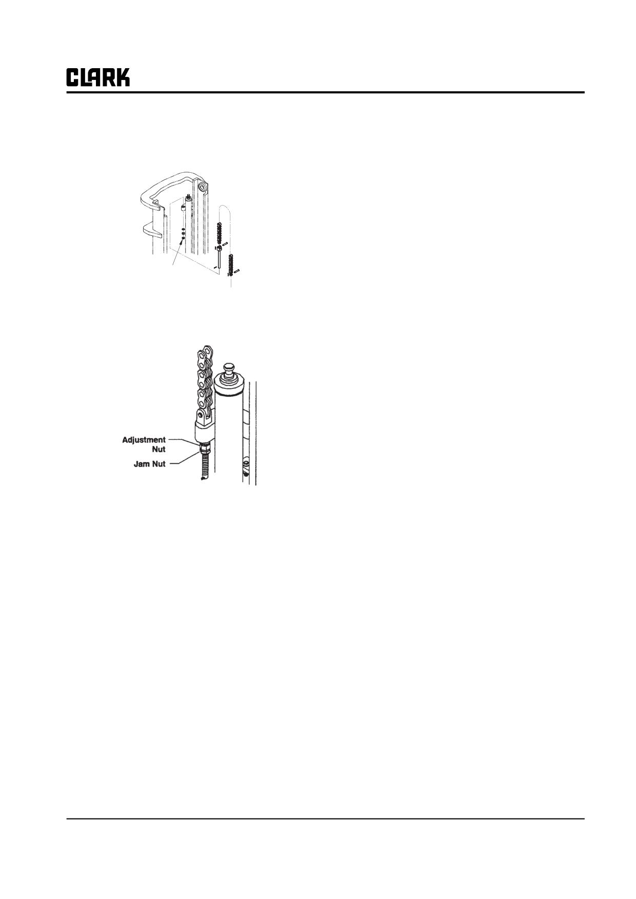
Group 34, Uprights
Standard Upright Chain Length Adjustment
3. Carriage stop-to-upright:
a. Lift upright to its full height and check for clear-
To adjust chain length on the standard upright use the fol-
ance on the carriage safety stop.
lowing illustration and procedures:
b. If the carriage stop hits the upright stop, adjust
the chain anchor adjustment nuts out until there is
at least 3 mm (0.12 in) clearance between the
stops.
IMPORTANT
The carriage stop must not be allowed to con-
tact the upright stop under any circumstance
during normal operations.
Adjust chain
length here
To carriage
If all three chain length requirements listed above cannot
be met, the tire diameter may be out of the design range
1. Fork-to-ground clearance:
allowance. Also, excessive tire wear will decrease carriage
a. Set the upright to vertical position.
stop clearance.
b. Break the jam nuts loose on the chain anchors.
Oversized tires will reduce the bottom carriage roller
engagement on the inner rail when the carriage is in the
lowered position. The fork-to-ground clearance can devi-
ate from the 10-20 mm (0.40-0.80 in) allowance by a
small amount if necessary to maintain the safe 20 mm
(0.80 in) clearance of the bottom carriage roller to the
lower edge of the inner rail.
Triple-Stage and Hi-Lo Upright Chain
Length Adjustments
c. Turn the chain adjustment nuts until clearance
Triple-stage uprights use two chain sets; one set for car-
between forks and ground is 10-20 mm (0.40-
riage lift and one set for rail lift. Adjustment anchors for
0.80 in).
the lift cylinder stage are located at the back of the outer
rail. Adjustment anchors for the primary lift stage are
IMPORTANT
behind the primary cylinder. Carriage chain anchors are
For all chain anchor adjustments:
not intended for adjustment.
• Threaded chain anchors must be left free to
pivot in mounting hole.
Hi-Lo Uprights use one chain set for carriage lift.
• Anchor cotter pin heads must be to the
For TSU inner rail lift chains, chain length must be
inside of the upright.
adjusted if the difference between the bottom of the inner
• Torque jam nuts to adjustment nuts to
rail and the outer rail is greater than 10 mm (0.40 in).
100-200 N⋅m (74-148 ft-lb).
• Make sure chain anchors are secured so
For the TSUand Hi-Lo primary cylinders lift chain, the
that no twist is evident in the chains.
chain length must be adjusted if:
2. Carriage roller position:
• The fork-to-ground clearance is less than 5 mm
a. Raise carriage about 1 m (3.2 ft) and smear a
(0.20 in) or more than 25 mm (1.0 in) when the
bead of grease on the bottom 75 mm (3 in) inner
upright is vertical.
rail in the area of the roller pattern.
• The center of the bottom carriage roller comes
b. Tilt upright fully back and completely lower.
within 20 mm (.80 in) of the bottom edge of the
c. Raise carriage about 1 m (3.2 ft) and measure the
inner rail.
distance from where the center of the bottom car-
• The carriage safety stop hits the inner rail stop at
riage roller stopped to the bottom edge of the
full lift height.
inner rail. Distance should not be less than 20 mm
(0.80 in) or chain length adjustment is required.
SM 765, Nov ’06
Upright Chain Inspection, Adjustment, and Replacement • 34-6-5
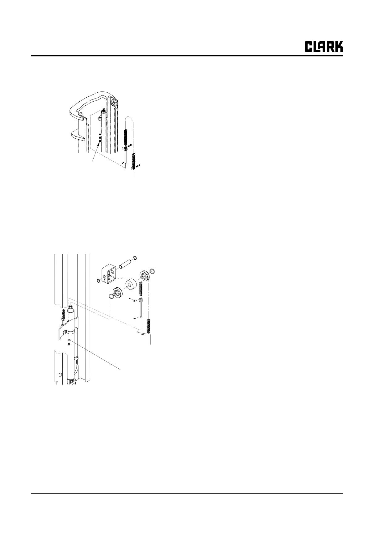
Group 34, Uprights
To adjust the cylinder lift chains on a TSU use the follow-
IMPORTANT
ing illustration and procedures:
For all chain anchor adjustments:
• Threaded chain anchors must be left free to
pivot in mounting hole.
• Anchor cotter pin heads must be to the
inside of the upright.
• Torque jam nuts to adjustment nuts to
100-200 N⋅m (74-148 ft-lb).
• Make sure chain anchors are secured so
that no twist is evident in the chains.
Adjust chain
length here
2.
Carriage roller position:
a. Raise carriage about 1 m (3.2 ft) and smear a
To inner rail
bead of grease on the bottom 75 mm (3 in) of the
inner rail in the area of the roller pattern.
1. Set the upright in the vertical position.
b. Tilt upright fully back and completely lower.
2. Break the jam nuts loose on the chain anchors.
c. Raise carriage again about 1 m (3.2 ft) and mea-
sure the distance from where the center of the
3. Adjust the chain anchor adjustment nuts until the
bottom carriage roller stopped to the bottom edge
bottom of the inner rail is within 2.5 mm (0.10 in) of
of the inner rail. Distance should not be less than
the bottom of the outer rail.
20 mm (0.80 in) or chain length adjustment is
To adjust the primary cylinder lift chain on TSU and Hi-
required.
Lo use the following illustration and procedures:
3.
Carriage stop-to-upright:
a. Lift upright to its full height and check for clear-
ance on the carriage safety stop.
b. If the carriage stop hits the upright stop, adjust
the chain anchor adjustment nuts out until there is
at least 3 mm (0.12 in) clearance between the
stops.
IMPORTANT
The carriage stop must not be allowed to con-
tact the upright stop under any circumstance
during normal operations.
To carriage
If all three chain length requirements listed above cannot
be met, the tire diameter may be out of the design range
allowance. Also, excessive tire wear will decrease carriage
Adjust chain
length here
stop clearance.
Oversized tires will reduce the bottom carriage roller
1. Fork-to-ground clearance:
engagement on the inner rail when the carriage is in the
a. Set the upright to vertical position.
lowered position. The fork-to-ground clearance can devi-
b. Break the jam nuts loose on the chain anchors.
ate from the 10-20 mm (0.40-0.80 in) allowance by a
c. Turn the chain adjustment nuts until clearance
small amount if necessary to maintain the safe 20 mm
between forks and ground is 10-20 mm (0.40-
(0.80 in) clearance of the bottom carriage roller to the
0.80 in).
lower edge of the inner rail.
34-6-6 • Upright Chain Inspection, Adjustment, and Replacement
SM 765, Nov ’06
Group 34, Uprights
Failure to follow these warnings can result in
Chain Lubrication
serious injury. See “Lifting, Jacking, and
Like all bearing surfaces, the precision-manufactured,
Blocking” for safe blocking procedures.
hardened-steel, joint-wearing surfaces of leaf chain
require a film of oil between all mating parts to prevent
General Guidelines
accelerated wear.
Maintaining a lubricant film on all chain surfaces will:
• Chain Movement - Make sure that the chain oper-
ating path is clear and that the chain articulates
• Minimize joint wear.
freely through its full range of operation.
• Improve corrosion resistance.
• Lubrication - Assure that the chain is well lubri-
• Reduce the possibility of pin turning.
cated with the heaviest oil that will penetrate the
• Minimize tight joints.
void between the link plate apertures and the pins.
• Promote smooth, quiet chain action.
• Paint - Make sure the chain does not get painted
over at any time.
• Lower chain tension by reducing internal friction
in the chain system.
• Protection - Where necessary, as a protection from
atmosphere or sliding wear, the chain may be cov-
Laboratory wear tests show #40 oil to have greater ability
ered with a layer of grease. It should be noted,
to prevent wear than #10 oil. Generally, the heaviest
however, that the grease will have to be removed at
(highest viscosity) oil that will penetrate the joint is best.
a later date for chain inspection and relubrication.
Whatever method is used, the oil must penetrate the chain
• Chain Mountings - Double check to be sure all
joint to prevent wear. Applying oil to external surfaces
chain fastening devices are secured and all adjust-
will prevent rust, but oil must flow into the live bearing
ments have been made to assure uniform loading
surfaces for maximum wear life.
of multiple chain applications. Check chain
anchors and pins for wear, breakage, and misalign-
To prepare the chain for oiling, the leaf chain plates
ment. Damaged anchors and pins should be
should be brushed with a stiff brush or wire brush to clear
replaced.
the space between the plates so that oil may penetrate the
live bearing area.
• Sheaves - Sheaves with badly worn flanges and
outside diameter should be replaced. This wear
Oil may be applied with a narrow paint brush or directly
may be due to chain misalignment or frozen bear-
poured on. Chain should be well flooded to be sure the oil
ings.
penetrates the joint.
In locations difficult to reach, it may be necessary to use a
Lift Chains (Standard and TSUs)
good quality oil under pressure such as an aerosol can or
pump pressure spray.
To remove and replace the lift cylinder and/or carriage
chain set on standard and triple-stage uprights (TSU):
Chain Removal and Replacement
1. Attach a hoist strap on the carriage of the standard
upright or inner rail of the TSU.
! WARNING
2. Lift the carriage or inner rail slightly to create slack
in the chains. Block the carriage or inner rail up for
The procedures for removing and replacing
safety.
chain sets involve hoisting and blocking com-
ponents.
3. Remove the chain anchor pins on the outer rail and
pull the chains off of the sheaves on the inner or
• Do not walk or stand under raised forks.
intermediate rails.
• Keep your arms and fingers away from
moving parts of the upright.
• Do not reach through open areas of the
upright.
SM 765, Nov ’06
Upright Chain Inspection, Adjustment, and Replacement • 34-6-7
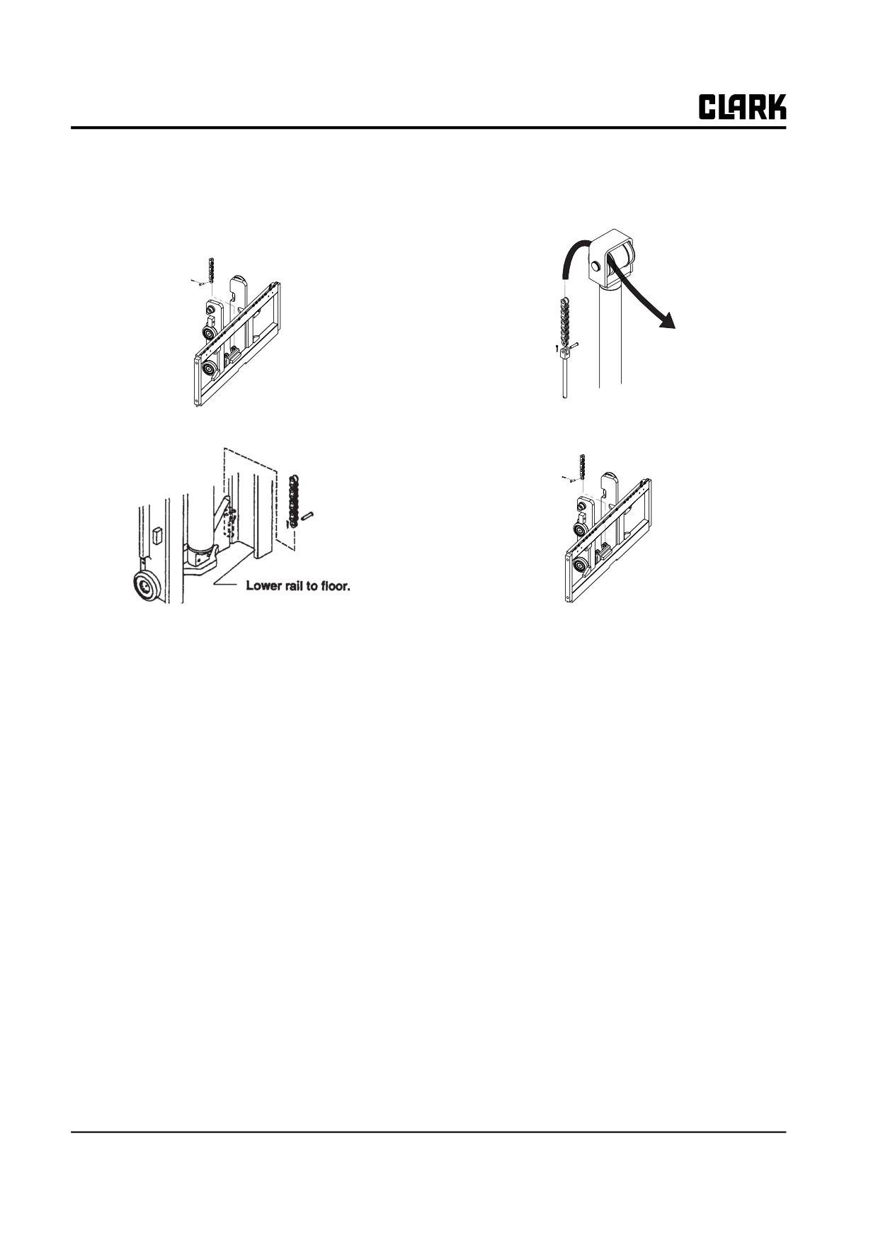
Group 34, Uprights
4. Remove the chain anchor pins from the carriage on
2. Remove the chain anchor pins from the back of the
the standard upright or the inner rail on the TSU. On
primary cylinder. Pull the chains through the chain
the TSU, the inner rails must be lowered to the floor
sheave and lay over the carriage load backrest.
to access the chain anchor pins.
3. Remove the chain anchor pins from the back of the
Lift Chain Removal from Carriage (standard upright)
carriage.
Triple-Stage Upright Lift Chain Removal from Inner Rail
4. Use these steps in reverse to replace the primary cyl-
inder/carriage chain.
NOTE
Perform the chain length adjustment and chain tension
If a hose adapter assembly is used, the chain
check before returning the truck to service.
sheaves must be loosened and removed to
prevent the hoses from stretching when the
inner rails of the TSU are lowered to access
Other Chain Service Notes
the chain anchor pins.
• Use lengths of factory assembled chain. Do not
5. Use the steps in reverse order to replace the lift chain
build lengths from individual components.
set.
• Do not attempt to rework damaged chains by
replacing only the components obviously faulty.
The entire chain may be compromised and should
Primary Cylinder/Carriage Chains (TSU
be discarded.
and Hi-Lo)
• Never electroplate assembled leaf chain or its com-
1. Tilt the upright forward, lower it, and completely col-
ponents. Plating will result in failure from hydro-
lapse the primary cylinder to create slack in the
gen embrittlement. Plated chains are assembled
chains. The carriage may also be lifted and blocked
from modified, individually plated components.
in position and the primary cylinder completely col-
• Welding should not be performed on any chain or
lapsed to create slack in the chains.
component. Welding spatter should never be
allowed to come in contact with chain or compo-
nents.
• Leaf chains are manufactured exclusively from
heat treated steels and therefore must not be
annealed. If heating a chain with a cutting torch is
absolutely necessary for removal, the chain should
not be reused.
34-6-8 • Upright Chain Inspection, Adjustment, and Replacement
SM 765, Nov ’06
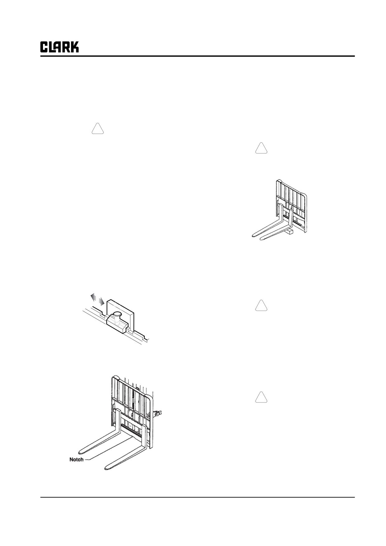
Group 34, Uprights
Section 7
Fork and Carriage Removal and Replacement
3.
Lift tip of each fork and put a 100 x 100 mm (4 x 4
! CAUTION
in) block under the fork arm near the heel.
SAFE PARKING. Before working on truck:
!
CAUTION
1. Park truck on a hard, level, and solid sur-
face, such as a concrete floor with no gaps
Forks weight 44-99 kg (97-220 lbs) each. Take
or breaks.
care when lifting.
2. Put upright in vertical position and fully
lower the forks or attachment.
3. Put all controls in neutral. Turn key
switch OFF and remove key.
4. Apply the parking brake and block the
wheels.
Fork Removal
NOTE
Blocking the Fork
Forks do not need to be removed to remove
the carriage.
4.
Push down on tips of the forks to disengage the fork
hooks from the carriage fork bar.
1.
Release the fork latches.
5.
Lift fork heel and remove block.
!
CAUTION
Forks are not stable sitting free in upright
position. Use care when working around the
forks.
Latch Operation
6.
Back the truck away from the forks.
2.
Move each fork to the notch on the bottom of the
lower carriage cross bar.
Fork Replacement
1.
Carefully drive truck up close to forks.
! CAUTION
Forks are not stable sitting free in upright
position. Use care when working around the
forks.
2.
Drag forks into position close to carriage and to line
up with the notche on the lower carriage cross bar.
3.
Lift fork heel and place block under arm near the
heel.
SM 765, Nov ’06
Fork and Carriage Removal and Replacement • 34-7-1
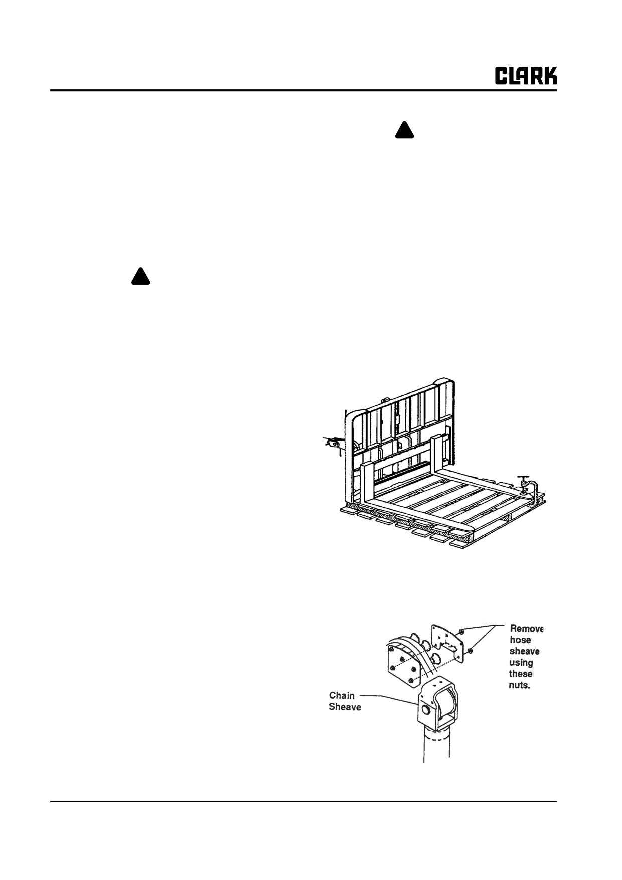
Group 34, Uprights
4. Lift tips of forks to engage the fork hooks on the
!
WARNING
upper carriage fork bar.
You may need to pull on the hoses/cables and
5. Remove blocks from under fork.
chains while lowering the primary cylinder to
6. Check fork latches when repositioning forks to upper
get it all the way down. This is done to create
carriage fork notches.
slack in hoses/cables and chains and to dis-
place as much oil as possible, which will
reduce oil loss when disconnecting hydraulic
Carriage Removal
lines for auxiliary components.
The carriage should be removed for shimming or when
You may need a helper to hold the control
any service procedure is performed on the upright.
handle in the lowering position while you pull
on the carriage chains to fully collapse the
! WARNING
primary cylinder (on Hi-Lo & TSUs). When
The procedures for checking, maintaining,
pulling on the chains to lower the primary
and adjusting uprights, carriages, and forks
cylinder (on Hi-Lo & TSUs), the ignition
involve movement of the components.
must be off.
• Do not walk or stand under raised forks.
4.
Once the carriage is fully lowered, clamp the front of
one fork to the pallet to prevent the carriage from
• Keep clear of load and carriage when mak-
falling over backwards when removed.
ing any check or adjustment.
• Keep your arms and fingers away from
moving parts of the upright.
• Do not reach through open areas of the
upright.
• Always use a prybar to move the upright or
carriage.
Failure to follow these warnings can result in
serious injury.
1. Set upright tilt to 0 degrees (vertical). Raise the car-
riage about 12 in (305 mm).
2. Place a heavy pallet under the forks. Turn the key off.
3. Lower the carriage onto the pallet and keep lowering
(until the primary cylinder is all the way down on
5.
For carriage auxiliary components, the hose sheave
TSUs and Hi-Lo). Before proceeding with the next
bracket must be unbolted from the primary cylinder
step read the following warning.
chain sheave bracket. Move the hose bracket off the
chain bracket.
34-7-2 • Fork and Carriage Removal and Replacement
SM 765, Nov ’06
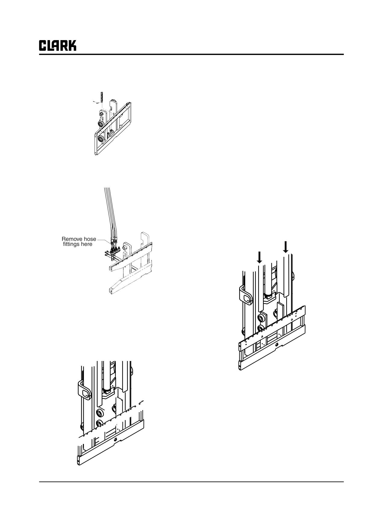
Group 34, Uprights
6. Disconnect the carriage chains at the base of the car-
10. Remove steer wheel blocks. Release the parking
riage. Pull chains back off primary cylinder sheave.
brake and slowly back the truck away from the car-
riage.
11. Lower the upright rails until both of the secondary
cylinders are completely collapsed.
Carriage Replacement
To replace the carriage:
1. First check to be sure the carriage is securely
clamped to the pallet.
7. For carriage auxiliary components, disconnect hoses
2. Move the truck up to the carriage assembly with the
(2- or 4-hose assemblies) from carriage. Remove the
inner rail centered on the carriage.
bolts and strap fixture also.
3. Raise the upright until the inner rail is high enough to
clear the upper carriage rollers.
4. Tilt the upright until it is at the same angle as the car-
riage assembly.
5. Now slowly move the truck forward until the inner
rail is centered over the carriage rollers.
• Cap all lines to prevent leaks.
• Label all lines and fittings for correct reassembly.
8. Elevate the primary cylinder to its maximum height.
Be sure all hoses and loose parts are secured out of
the way to prevent damage.
9. Continue elevating the upright until the inner rail
clears the carriage.
SM 765, Nov ’06
Fork and Carriage Removal and Replacement • 34-7-3
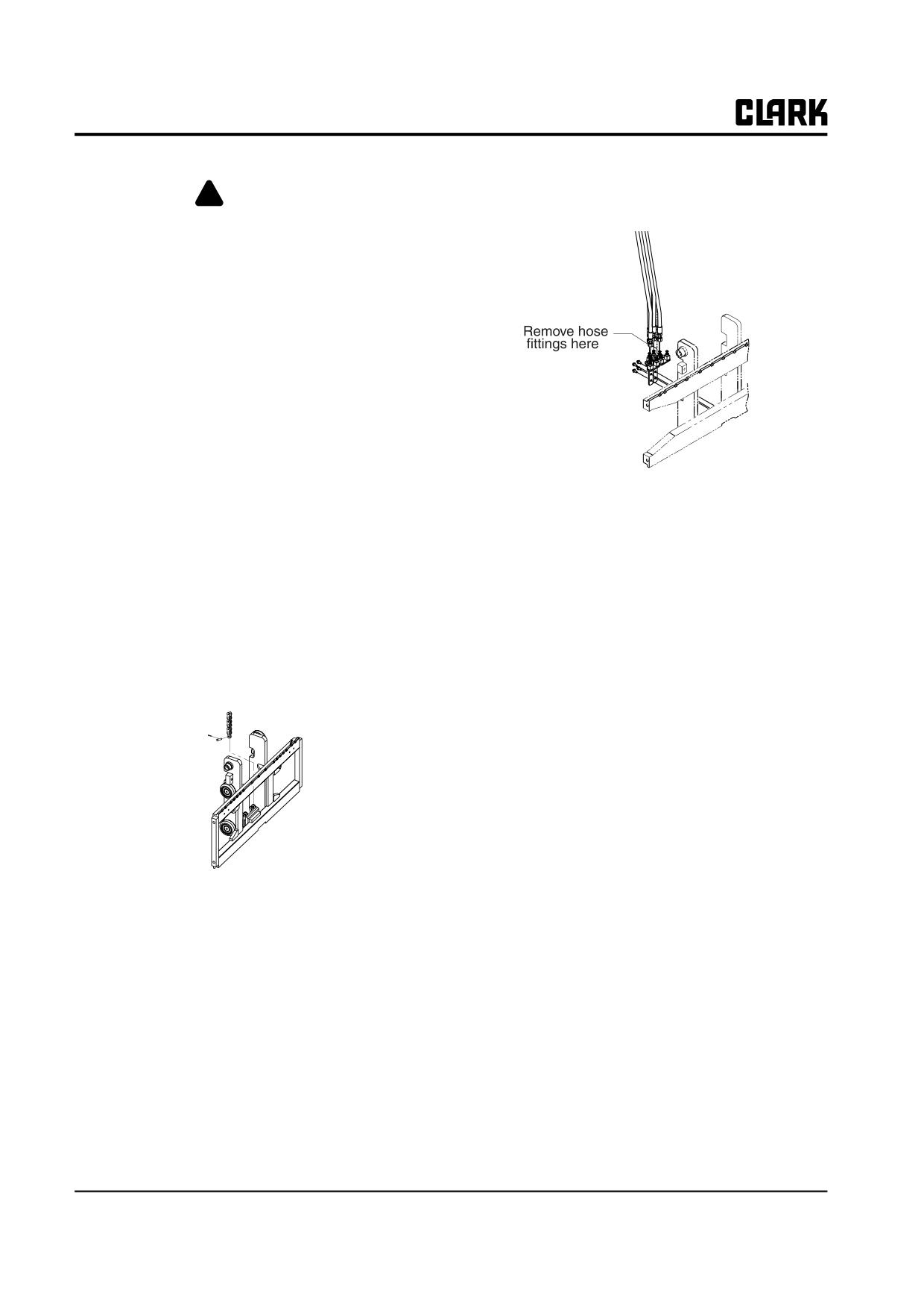
Group 34, Uprights
10. Reconnect the hoses and mounting strap to the car-
! WARNING
riage auxiliary component if the carriage is so
Never attempt to move or align the carriage
equipped.
or bearings by hand. Use a pry bar.
6. Lower the upright until the inner rail clears all of the
carriage rollers.
NOTE
If the rail or bearings bind, raise the upright,
back away from the carriage and check to be
sure the carriage rollers are installed prop-
erly.
7. When the inner rail has cleared the carriage rollers,
continue to lower the upright until the lift cylinders
are lowered completely.
• Lubricate all O-rings with a light coating of system
8. Reset the truck in a safe position:
hydraulic fluid or a compatible oil.
• Ignition off
• Use two wrenches to tighten hose fittings to pre-
• Parking brake applied
vent hoses from twisting.
• Directional lever in neutral
• See Group 40 for hydraulic fitting tightening pro-
cedures.
• Forks completely lowered
• Block steer wheels.
11. Adjust carriage height according to Section 6 and
chain tension according to Section 3.
9. Reinstall the carriage lift chains to the base of the
carriage.
12. Remove the “C” clamp from the pallet and check the
operation of the carriage and the upright. Carefully
check for oil leaks. Make sure the carriage and
upright work smoothly and correctly before returning
the truck to service.
• Set anchor bolts so that no twist develops in the
chains.
• Anchor pin heads must be pointing to the inside of
the upright.
• Use new cotter pins.
IMPORTANT
Always use new anchor pins when replacing
chain sets.
34-7-4 • Fork and Carriage Removal and Replacement
SM 765, Nov ’06
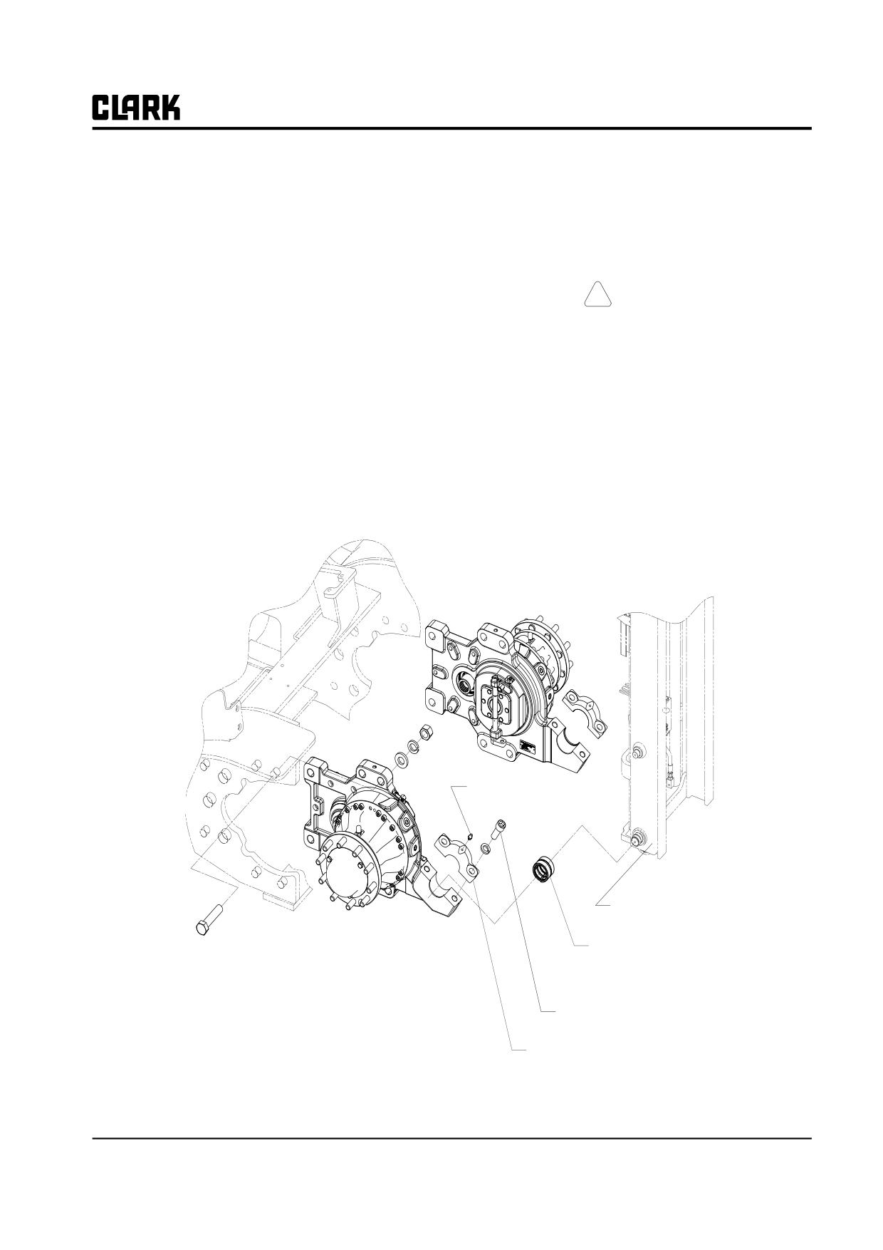
Group 34, Uprights
Section 8
Upright Removal and Replacement
This Section describes how to remove the entire upright
!
CAUTION
assembly from the truck. The carriage and forks must be
removed from the upright assembly before the upright is
SAFE PARKING. Before working on truck:
removed. (For uprights with an auxiliary component, a
1. Park truck on a hard, level, and solid sur-
side-shifter for example, the two hydraulic hoses power-
face, such as a concrete floor with no gaps
ing the auxiliary component must be removed before the
or breaks.
carriage is removed.) See Section 7, “Fork and Carriage
Removal and Replacement,” for procedures to remove the
2. Put upright in vertical position and fully
carriage and fork assembly from the upright.
lower the forks or attachment.
3. Put all controls in neutral. Turn key
switch OFF and remove key.
4. Apply the parking brake and block the
wheels.
Nipple-grease
Outer rail set
Bushing
Bolt of upright mounting
Mounting cap
Typical Upright Installation
SM 765, Nov ’06
Upright Removal and Replacement • 34-8-1
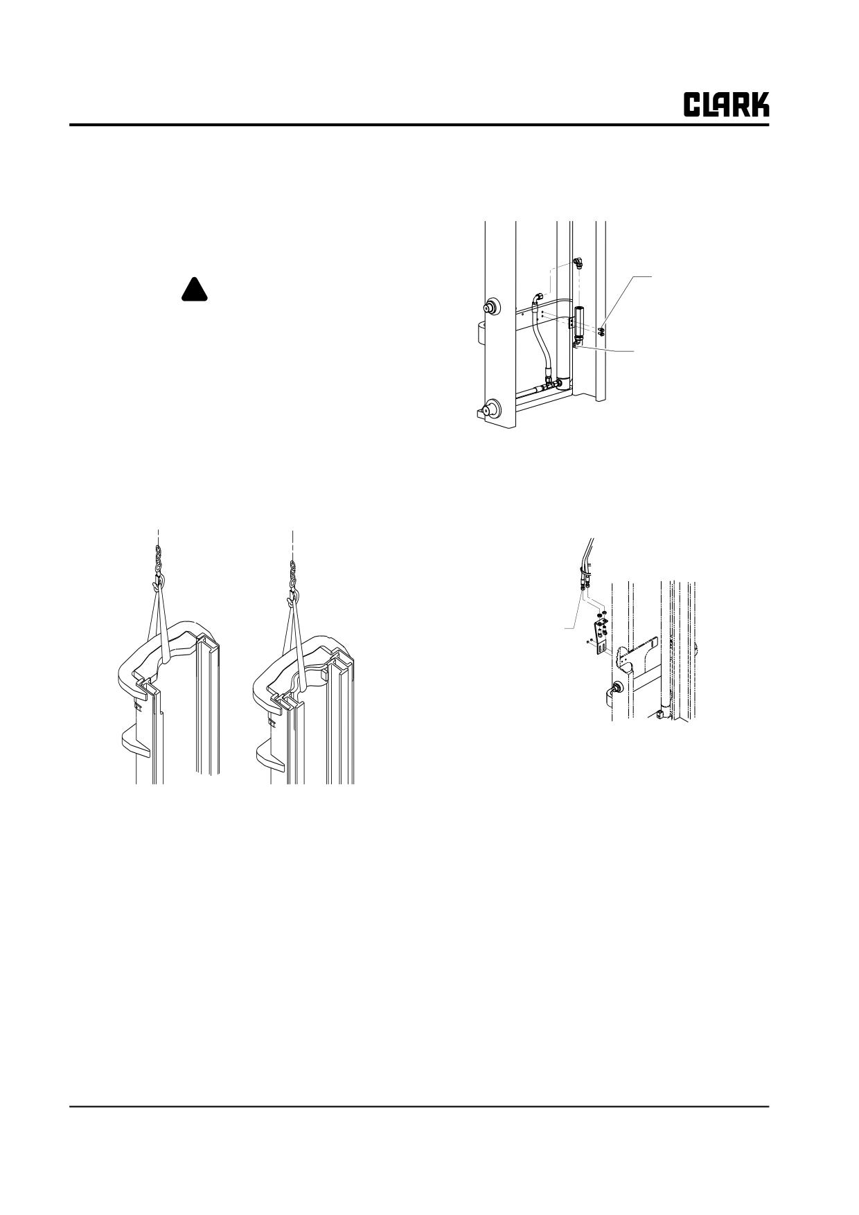
Group 34, Uprights
2. Disconnect and cap hydraulic line at the load-lower-
Upright Removal
ing flow valve. Secure the hose out of the way of the
The following procedures are for uprights with carriage
upright.
and forks, or auxiliary components removed. See Section
7, “Fork and Carriage Removal and Replacement,” for
instructions on removing the forks and carriage.
Remove the
mounting bolts
! WARNING
from the manifold
The upright assembly is heavy. Use only
hoists with enough capacity to lift the entire
assembly. Keep clear of the assembly as it is
Disconnect
and cap line from
being hoisted and set down. Keep hands and
main hydraulic
feet away from the assembly. Use prybars to
control valve.
move the assembly into position for reattach-
ment.
1. Attach a hoist and strap of adequate capacity to the
NOTE
upright as shown below. Tension the hoist so that the
For two-hose adapter assemblies, the hydrau-
upright cannot fall when upright mounting pins and
lic lines to the upright must also be discon-
tilt cylinder pins are removed.
nected and capped.
Disconnect
lines here
34-8-2 • Upright Removal and Replacement
SM 765, Nov ’06
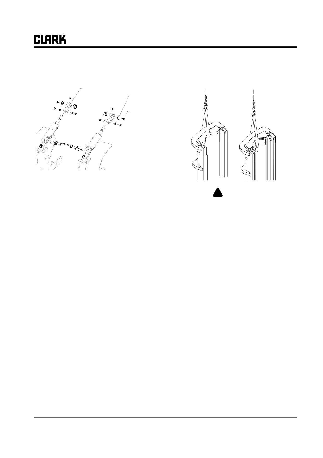
Group 34, Uprights
3. Remove tilt cylinder rod-end lock plates and rod-end
Upright Replacement
pins from upright.
1. Use an overhead chain hoist of adequate capacity and
an approved lift chain to lift upright into position.
Tilt cylinder
Rod end
Tilt cylinder
Mounting
Tilt cylinder
mounting Bolt
4. Remove trunnion ring bolts and lift upright off frame.
See illustration on page 1.
!
WARNING
5. Slowly set upright down on the floor, 100 x 100 mm
Use prybars to move the assembly into posi-
(4 x 4 in) blocking, or sturdy pallets set end-to-end.
tion for reattachment.
SM 765, Nov ’06
Upright Removal and Replacement • 34-8-3
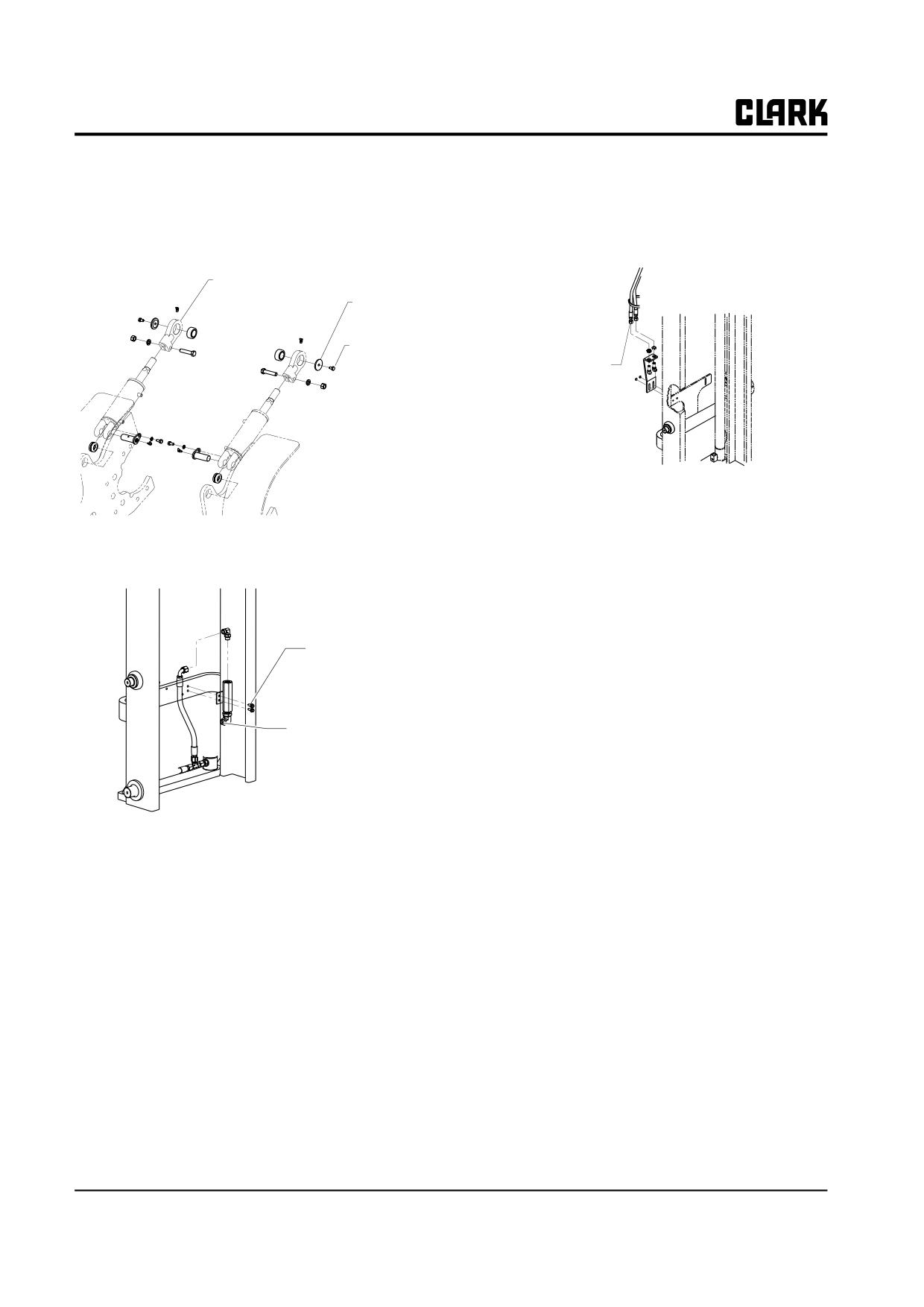
Group 34, Uprights
2. Install rod end pins, lock plates, and fasteners.
NOTE
Tighten lock plate fasteners to a torque of 40-45 N⋅m
Reconnect two-hose adapter assembly
(30-33 ft-lb).
hydraulic lines to the upright-mounted
bracket.
Tilt cylinder
Rod end
Tilt cylinder
Mounting
Tilt cylinder
mounting Bolt
Reconnect
lines here
4. Remove the lift chain between the upright and hoist.
5. Completely check all upright and hydraulic compo-
nents under load before returning the truck to service.
3. Attach hydraulic lines to the upright flow control
valve:
6. See Section 8, “Fork and Carriage Removal and
Replacement,” for steps to replace the carriage and
fork assembly.
Connect the
mounting bolts
to the manifold
Reconnect
line here
• Lubricate all O-rings with a light coating of system
hydraulic fluid or a compatible oil.
• Use two wrenches to tighten hose fittings to pre-
vent twisting lines.
• See Group 40 for hydraulic fitting tightening pro-
cedures.
34-8-4 • Upright Removal and Replacement
SM 765, Nov ’06
GROUP 38
GROUP 38
COUNTERWEIGHT AND CHASSIS
Counterweight Specifications and Description ... Section 1
Counterweight Removal and Installation
Section 2
Overhead Guard Removal and Installation
Section 3
Floor Plate, Seat and Seat Deck Removal
and Installation
Section 4
SM 765, Dec ’06
Group 38, Counterweight and chassis
NOTE :
Group 38, Counterweight and chassis
SM 765, Dec ’06
Group 38, Counterweight and Chassis
Section 1
Counterweight Specifications and Description
Specifications
2
Description
2
General Maintenance
2
SM 765, Nov ’06
Counterweight Specifications and Description • 38-1-1
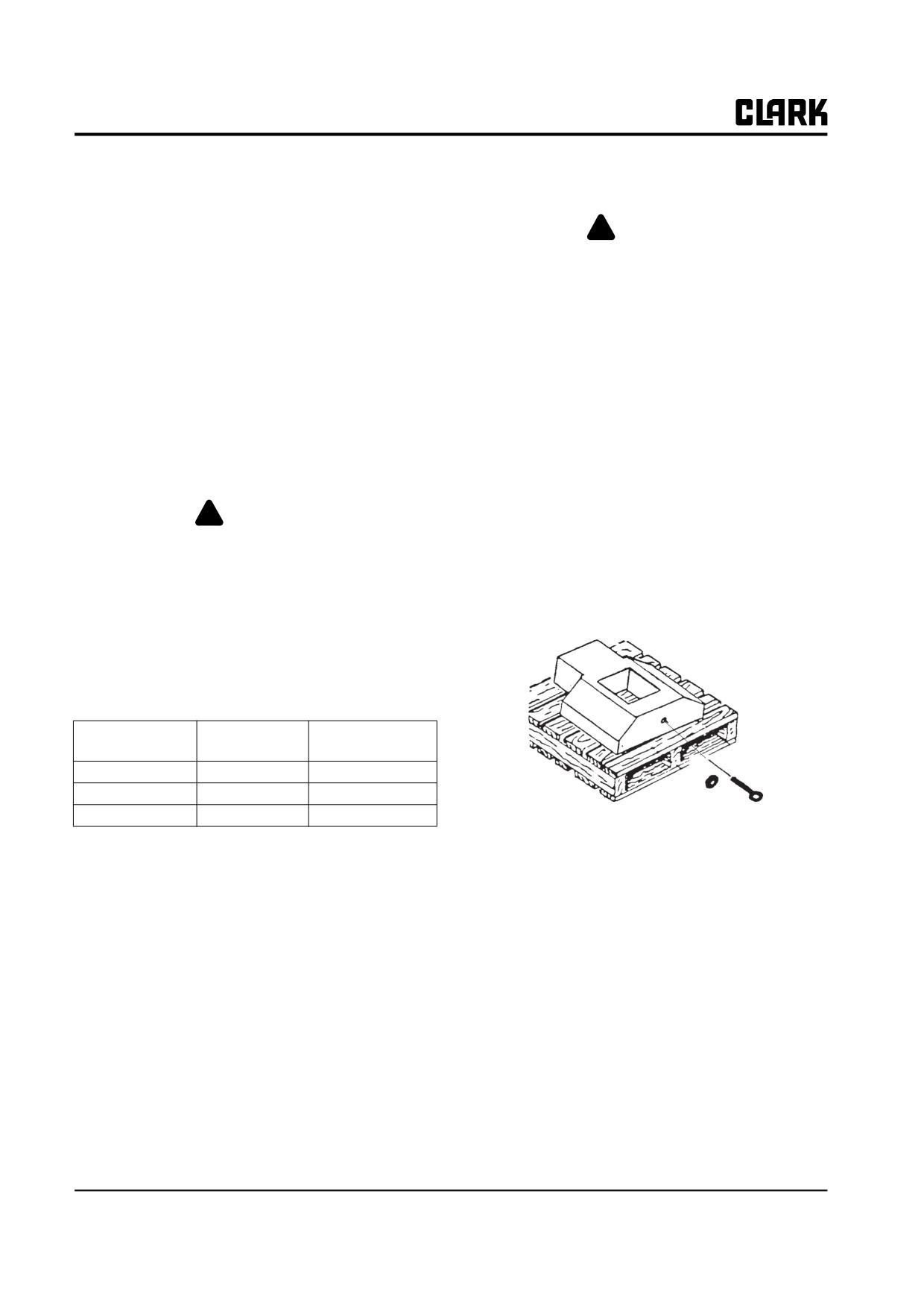
Group 38, Counterweight and Chassis
Specifications
General Maintenance
Fastener Torques
!
WARNING
The counterweight is extremely heavy. Do not
Counterweight Mounting Bolts: 340-380 N.m (25l-280
remove the counterweight unless you have
lb-ft)
training and are familiar with the correct
procedures. Counterweights can fall if not
Description
handled correctly and can cause severe
injury or death. Keep your hands, feet, and
The counterweight is a solid, cast-iron piece mounted to
body clear of the counterweight at all times.
the back of the lift truck. It is used to counterbalance the
Hoisting equipment must be capable of han-
loads placed on the upright at the front of the truck. The
dling the weight of the counterweight when
weight must be great enough to counteract forward tip-
removing or replacing. Make sure your lift-
ping when lifting or stopping with a capacity load. The
ing equipment is of adequate capacity to han-
battery provides much of the counterweight on an electric
dle the weight.
truck.
The counterweight must be maintained in good condition
! WARNING
and securely attached to the lift truck. Because of its
heavy weight and bulky mass, the counterweight must be
The minimum battery weight for your truck
carefully supported and handled. When removed from the
is stamped on the nameplate. Never operate
truck, store at floor level as shown below to be sure it will
the truck with a battery that weighs less.
not fall or tip, causing damage or injury.
Large, hardened steel bolts hold the counterweight to the
frame.
Different counterweights are used based on truck capacity
and battery compartment length.
Counterweight weights(GEX):
Short wheel base
Long wheel base
28.2 BC
33.9 BC
560 kg (1235 lbs)
GEX20
-
760 kg (1675 lbs)
GEX25
-
720 kg (1587 lbs)
-
GEX30
Generic Illustration
38-1-2 • Counterweight Specifications and Description
SM 765, Nov ’06
Group 38, Counterweight and Chassis
Section 2
Counterweight Removal and Installation
Conterweight Removal
2
Counterweight Installation
3
SM 765, Nov ’06
Counterweight Removal and Installation • 38-2-1
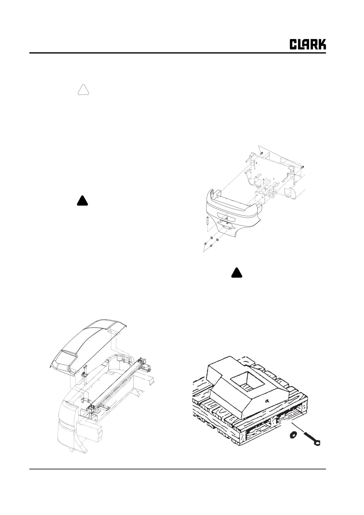
Group 38, Counterweight and Chassis
4.
Raise the hood of operator's seat, and remove the bat-
Counterweight Removal
tery
! CAUTION
5.
Install the eyebolt in the counterweight. The eyebolt
should bear 1193kg(2630lb).
SAFE PARKING. Before working on truck:
6.
Using an overhead hoist with sufficient lifting capac-
1. Park truck on a hard, level and solid sur-
ity, attach hoist chain to eye bolt. Slowly lift hoist
face, such as a concrete floor with no
until slack is removed from chain.
gaps or breaks.
7.
Remove the counterweight mounting bolts.
2. Put upright in vertical position and fully
Counterweight mounting fastner
lower the forks or attachment.
3. Put all controls in neutral. Turn key
switch OFF and remove key.
4. Apply the park brake and block the
wheels.
! WARNING
Observe proper, safe lifting practices when
lifting counterweight on or off truck.
Counterweight should only be lifted by
appropriately-sized eye bolt installed
through the top lifting hole.
Counterweight mounting fastner
Use only overhead lifting equipment having a
safe lifting capacity in excess of that of the
counterweight.
!
WARNING
1.
Remove the Electronic Controls cover.
Stand clear of the counterweight as it is being
hoisted, moved, or mounted.
2.
Remove the controller from the counterweight.
3.
Remove the battery connector from the counter-
8.
Slowly lift the counterweight from the truck frame
weight.
until it is free from the counterweight hooks on the
frame and can be moved back to clear the eleclronic
controls. Take care not to damage the controls.
9.
Slowly lower the counterweight onto a sturdy pallet.
Set the counterwcighl on its flat side if possible.
Generic Illustration
38-2-2 • Counterweight Removal and Installation
SM 765, Nov ’06
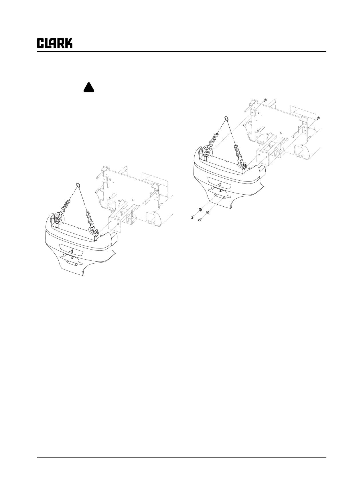
Group 38, Counterweight and Chassis
2. Inspect the counterweight mounting bolts to make
Counterweight Installation
sure they are in good condition before installing. Use
only Clark replacement parts. Torque the mounting
! WARNING
bolts to 340-380 N⋅m (251-280 lb-ft).
Stand clear of the counterweight as it is being
hoisted, moved, or mounted.
During mounting, always use prybars for
location adjustments. Do not place any part
of your body between the counterweight and
truck.
1. Place the counterweight fit to the mounting hole of
frame by use of the hoist and eyebolt.
3. Remove the hoist and eye bolls.
IMPORTANT
Never allow a truck to be put into service
without the counterweight mounting bolts in
place. Check the bolts and torque regularly.
Generic Illustration
SM 765, Nov ’06
Counterweight Removal and Installation • 38-2-3
NOTE :
Group 38, Counterweight Specifications and Description
SM 765, Nov ’06
Group 38, Counterweight and Chassis
Section 3
Overhead Guard Removal and Installation
Overhead Guard Removal
2
Overhead Guard Installation
2
SM 765, Nov ’06
Overhead Guard Removal and Installation • 38-3-1
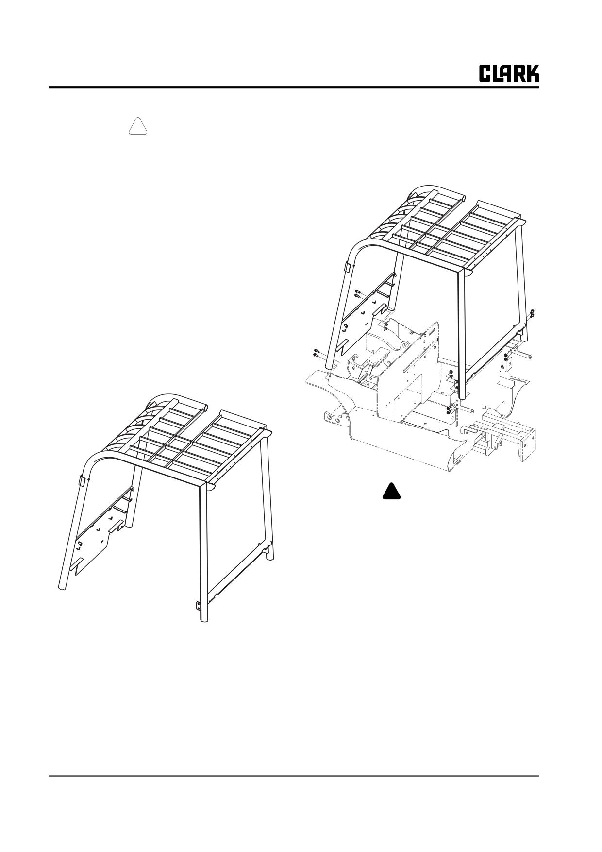
Group 38, Counterweight and Chassis
Overhead Guard Installation
! CAUTION
1. Put overhead guard in place on the truck chassis.
SAFE PARKING. Before working on truck:
2. Install the eight overhead guard mounting bolts.
1. Park truck on a hard, level and solid sur-
face, such as a concrete floor with no
Tighten to 88-95 N⋅m (65-70 lb-ft).
gaps or breaks.
2. Put upright in vertical position and fully
lower the forks or attachment.
3. Put all controls in neutral. Turn key
switch OFF and remove key.
4. Apply the park brake and block the
wheels.
Overhead Guard Removal
1. Remove the battery.
2. It is not anticipated that it should be necessary to
remove the overhead guard from the truck in thc-
coursc of normal service or repair. The instrument
panel/cowl assemblies are supported by the overhead
guard.
!
WARNING
Overhead guard must be in place to protect
operator from falling objects.
3. If the overhead guard shall be disassembled from the
fork lift truck for repair or replacement, make sure to
install the lifting hook to the overhead guard.
4. Remove the battery cover and control cover, and then
remove the floor. Disassemble all the kinds of wir-
ings from the overhead guard.
5. Remove the overhead guard mounting bolts.
6. Lift overhead guard from the truck
38-3-2 • Overhead Guard Removal and Installation
SM 765, Nov ’06
Group 38, Counterweight and Chassis
Section 4
Floor Plate, Seat and Seat Deck Removal and Installation
Floor Plate Removal and Installation
2
Operator’s Seat Deck Removal
2
Operator’s Seat Deck Reinstallation
3
SM 765, Nov ’06
Floor Plate, Seat and Seat Deck Removal and Installation • 38-4-1
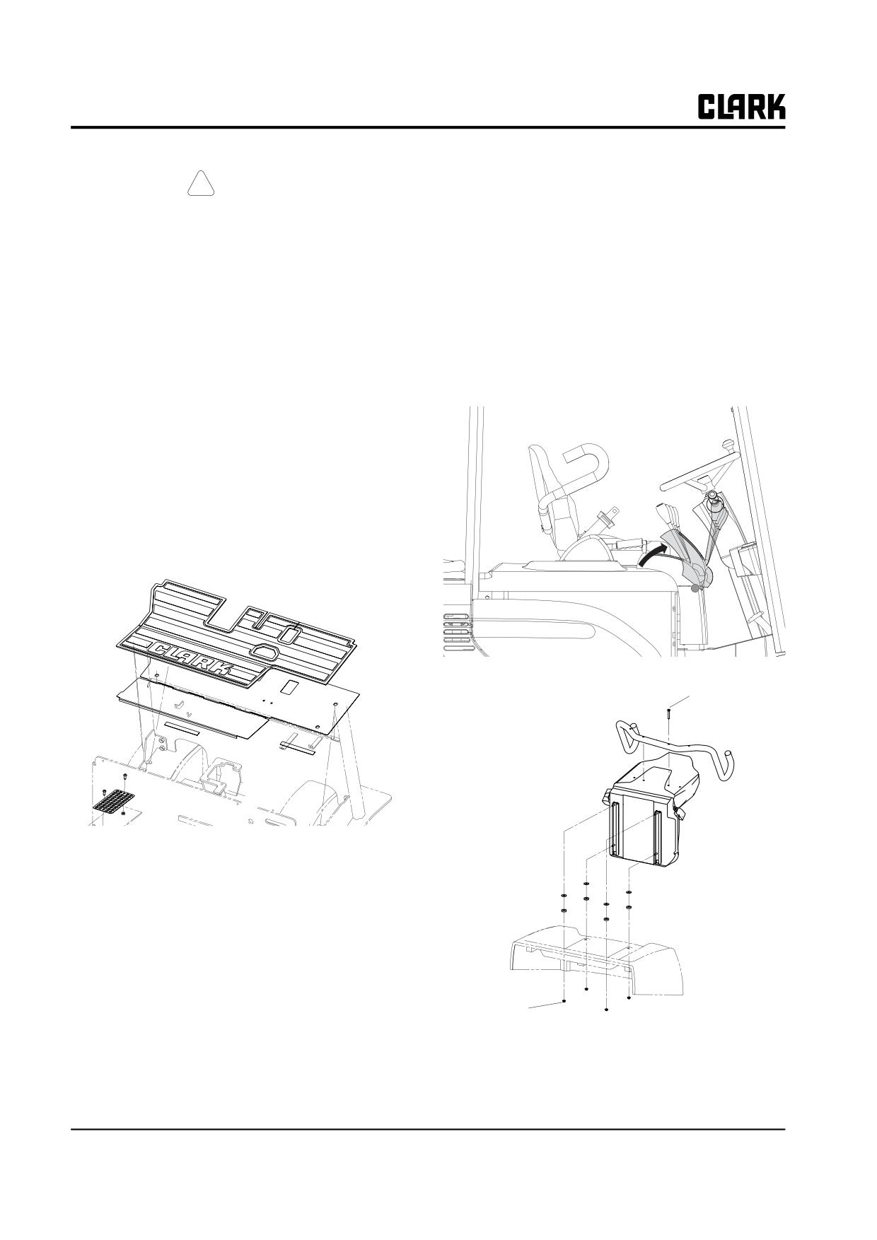
Group 38, Counterweight and Chassis
Operator's Seat Deck and Hood
! CAUTION
Removal and Installation
SAFE PARKING. Before working on truck:
1. Park truck on a hard, level and solid sur-
Removal
face, such as a concrete floor with no
gaps or breaks.
1. Push the hydraulic control lever bracket which locks
2. Put upright in vertical position and fully
the deck of operator's seat. Pull the handle on the
lower the forks or attachment.
right side of hydraulic control lever bracket and push
3. Put all controls in neutral. Turn key
the lever bracket forward, then the deck of operator's
switch OFF and remove key.
seat can be lifted.
4. Apply the park brake and block the
2. Remove the nuts holding the seat slide studs to the
wheels.
seat deck.
Floor Plate Removal and Installation
1. Tilt the steering column fully forward.
2. Fold the floor plate on its hinge and lift out the oper-
ator’s compartment. Rubber mat lifts out with floor
plate. Floor plate is not fastened to the truck.
3. To replace the floor plate, position the front of floor
plate first, then unfold it out into position.
Torque to :
6-13 N.m
(60-120 in-lb)
IMPORTANT
Make sure the accelerator pedal has a full
stroke and does not bind.
Torque to :
23-25 N.m
(203-221 in-lb)
3. The seat deck, which is held on the seat deck by the
seat mounting fasteners, may now also be removed.
38-4-2 • Floor Plate, Seat and Seat Deck Removal and Installation
SM 765, Nov ’06
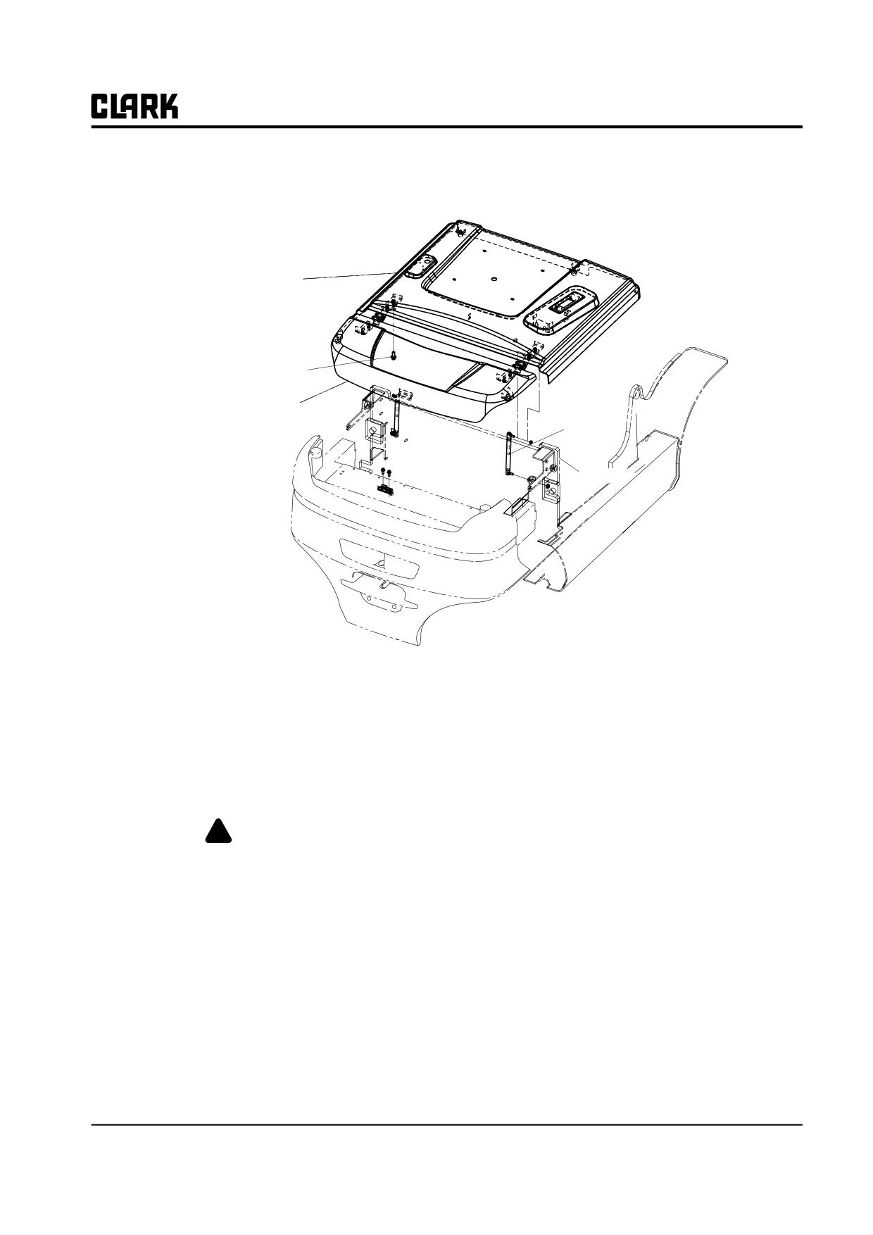
Group 38, Counterweight and Chassis
Seat Deck
Seat deck
mounting bolt
Rear hood
Gas spring
Frame
4. Remove the hood mounting fasteners and remove the
hood.
Reinstallation.
1. Reinstall the hood in reverse order that it was
removed.
! WARNING
Failure to follow this reinstallation procedure
may result in operator injury. Ensure full
latch engagement for battery retention.
SM 765, Nov '06
Floor Plate, Seat and Seat Deck Removal and Installation • 38-4-3
NOTE :
Group 38, Counterweight Specifications and Description
SM 765, Nov ’06
GROUP 40
GROUP 40
SPECIFICATIONS
Nameplate and Decals
Section 1
General Specifications
Section 2
Hydraulic Fitting Tightening Procedure
Section 3
SM 765, Nov ’06
Group 40, SPECIFICATIONS
NOTE :
Group 40, SPECIFICATIONS
SM 765, Nov ’06
Group 40, Specifications
Section 1
Nameplate and Decals
Nameplate and Decal Locations
2
Nameplate and Decals
4
SM 765, Nov ’06
Nameplate and Decals • 40-1-1
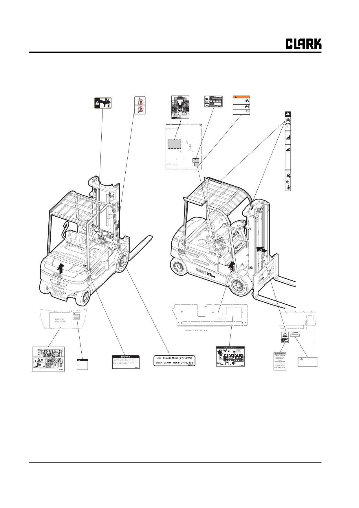
Group 40, Specifications
Nameplate and Decals Locations
WARNING
BEFORE OPERATING lift truck, operator must:
• Be trained and authorized.
• Read and understand operator's
manual.
• Not operate a faulty lift truck.
• Not repair lift truck unless trained and authorized.
• Have the overhead guard and load backrest
extension in place.
DURING OPERATION, lift truck operator must:
• Wear a seat belt.
• Keep entire body inside truck cab.
• Never carry passengers or lift people.
• Keep truck away from people and obstructions.
• Travel with lift mechanism as low as possible.
and tilted back.
TO PARK lift truck, operator must:
• Completely lower forks or attachments.
• Shift into neutral.
• Turn off key.
• Set parking brake.
WARNING
Read the
manual
Buckle up!
Apply brake
when leaving
truck
Watch Out
For Other
People
Most lift truck
INJURIES
are to other
people near
the lift truck.
Prevent
Overturns!
AVOID :
slippery,
sloping,
or uneven
surfaces
loads over
capacity on
nameplate
• unstable or
high loads
• low tire
pressure
poorly
maintained
lift truck
fast or
sharp turns
In Case of
Tip-Over:
Don't
jump
Hold on
tight
Brace feet
Lean
away
! WARNING
Disconnect battery before handling
WARNING
electrical components.
Connect positine to positive, negative
to negative to prevent damage.
40-1-2 • Nameplate and Decals
SM 765, Nov ’06
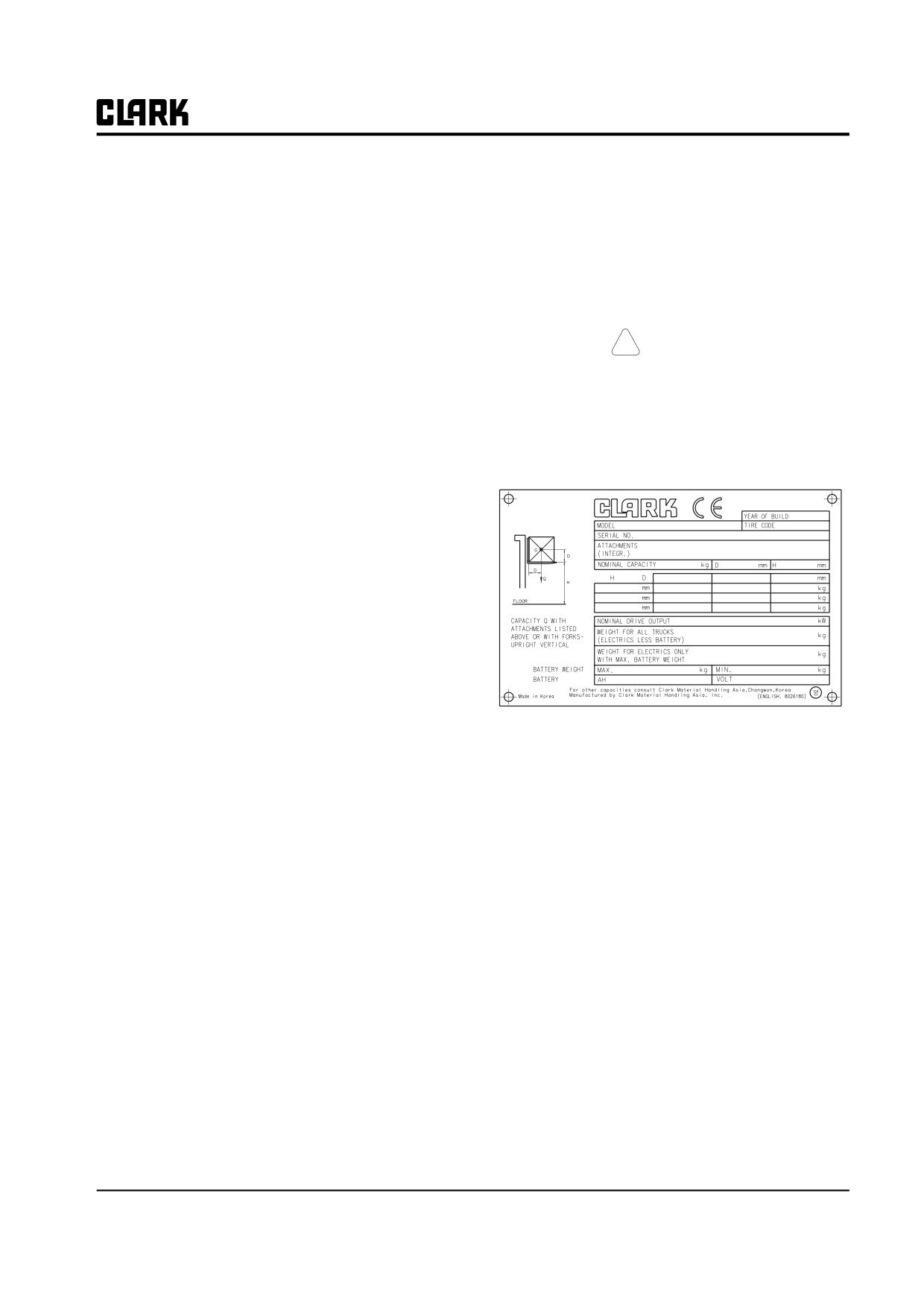
Group 40, Specifications
on plate). Personal injury and damage to the truck
Nameplate and Decals
can occur if these capacities are exceeded.
This section shows the nameplate (data and capacity
5. Truck weight - The approximate weight of the truck
plate) and decals required to be on all operating Clark
without a load on the forks. The truck weight plus the
industrial trucks. The nameplate lists the data on the truck
weight of the load must be considered when operat-
- type and serial number - and the capacities of the truck.
ing on elevators, elevated floors, etc., to be sure it is
Decals depict or explain the hazards the operator must
safe.
avoid when operating the truck. The nameplate and decals
are placed in specific locations on the truck and are
intended to warn others working around the truck of its
!
CAUTION
hazards as well. The nameplate and decals MUST BE IN
Before attachments are added, or if the truck
PLACE on all trucks.
is modified after leaving the factory, you
If any decals or the nameplate are missing from the truck,
must contact your authorized Clark dealer
check with your local Clark dealer for replacements. This
for authorization and a new nameplate as
is required by OSHA.
capacity will be affected. This is required by
OSHA.
IMPORTANT
Do not allow a lift truck with damaged or
missing decals or data plate to be placed in
service. Replace them immediately. They
contain important information as described
on the following pages. This is required by
OSHA. The location of all decals is also
shown on the following pages.
Truck Data and Capacity Plate
The truck data and capacity plate provides essential infor-
mation about the truck. This information is important for
both operators and service personnel. Operators can see
what the truck’s capacities and load ratings are. Service
personnel must identify the truck model, type, and serial
number when ordering parts. Refer to numbers on exam-
ple data plate illustration.
1. Truck model number or registered name.
2. Truck serial number--An identification number
assigned to this particular truck and should be used
when requesting information or ordering service
parts for this truck from your authorized CLARK
dealer. The serial number is also stamped on the
frame.
3. Attachment description (if any installed)--The user
must see that the truck is marked to identify the
attachment(s), including weight of the truck/attach-
ment combination and truck capacity with the attach-
ment.
4. Capacity rating, load center, and lifting height data
Shows the maximum load capacity of this truck with
relation to load centers and fork heights (see diagram
SM 765, Nov ’06
Nameplate and Decals • 40-1-3
Group 40, Specifications
Warning Decal
Operator Safety Decar
The Operator Safety Warning Decal describes basic safe
The Operator Safety Decal depicts
WARNING
operating procedures that should be used when operating
impotant points about truck operation
Read the
the truck. This decal depicts important points about truck
and warns operators about truck safety
manual
operation and warns operators about truck safety hazards.
hazards. The Operator Safety Decal is
This decal is meant as a reminder for operators. It is
meant as a reminder for operators and is
placed where operators can review the points daily as they
placed where operators can review the
Buckle up!
conduct a visual inspection and prepare the truck for
points daily as they conduct a visual
work.
inspection and prepare the truck for
work.
Apply brake
when leaving
truck
Watch Out
WARNING
For Other
People
BEFORE OPERATING lift truck, operator must:
Be trained and authorized.
Read and understand operator's
manual.
Not operate a faulty lift truck.
Most lift truck
INJURIES
Not repair lift truck unless trained and authorized.
are to other
Have the overhead guard and load backrest
people near
extension in place.
the lift truck.
DURING OPERATION, lift truck operator must:
Prevent
Wear a seat belt.
Overturns!
Keep entire body inside truck cab.
Never carry passengers or lift people.
Keep truck away from people and obstructions.
Travel with lift mechanism as low as possible.
and tilted back.
AVOID :
slippery,
sloping,
TO PARK lift truck, operator must:
or uneven
Completely lower forks or attachments.
surfaces
Shift into neutral.
loads over
Turn off key.
P
capacity on
nameplate
Set parking brake.
Clark Material Handling Co.
Sit Down Rider
2798233
unstable or
high loads
low tire
pressure
IMPORTANT
poorly
maintained
Safety and warning decals are placed in con-
lift truck
spicuous locations on the truck to remind
fast or
sharp turns
operators of essential procedures or to pre-
vent them from making an error that could
In Case of
damage the truck or cause personal injury.
Tip-Over:
Safety and warning decals should be replaced
Don't
jump
immediately if missing, damaged or illegible.
This is required by OSHA.
Hold on
Lift trucks can be tipped over if operated improperly.
tight
Experience with lift truck accidents has shown that the
driver cannot react quickly enough to jump clear of the
Brace feet
truck and overhead guard as the truck tips. To protect
Lean
operators from severe injury or death in the event of a tip-
away
over, make sure this decal is in place to remind them to
always use their seat belts.
2798235
40-1-4 • Nameplate and Decals
SM 765, Nov ’06
Group 40, Specifications
Hand Safety Warning Decal
Battery Disconnect Warning Decal
This safety decal is placed on the upright to warn of the
This warning decal is located on the front of the seat deck.
danger of injury from movement between rails, chains,
It warns of the danger of truck movement when removing
sheaves, fork carriage, and other parts of the upright
or inserting the battery connector by calling for turning
assembly. Operators and others should never climb on or
the key switch to OFF and setting the parking brake.
reach into the upright. Personal injury will result if any
body part is put between moving parts of the upright.
! WARNING
Turn key switch off
and set parking
brake before
removing
or inserting battery
2791862
connector.
Truck may start in
Keep Away from Forks Decal
motion if you do not.
This safety decal is placed on the upright to warn of the
2743642
danger of injury from forks when they are in the raised
position. Operators and others should never ride on or
stand under forks or attachments. The forks can fall and
cause injury or death.
Polarity Warning Decal
This warning decal is located on the front of the seat deck,
adjacent to the Battery Disconnect Warning Decal. It
notes the need to disconnect the battery before handling
electrical components and to always make electrical con-
nections positivc to positive and negative to negative to
prevent damage.
WARNING
Disconnect battery before handling
electrical components.
Connect positive to positive, negative
to negative to prevent damage.
SM 765, Nov ’06
Nameplate and Decals • 40-1-5
Group 40, Specifications
Electric Truck Warning Decal
This warning decal is located on the inside of the electri-
cal contactor compartment door. It warns that to prevent
unexpected movement of the truck when working on it, to
raise the drive wheels, disconnect the battery, discharge
the capacitors and refer to maintenance procedures.
!
WARNING
TRUCK CAN MOVE UNEXPECTEDLY!
BEFORE WORKING ON THIS TRUCK.
Raise drive wheels clear of operating surface.
Disconnect battery.
Discharge capacitor(s).
Refer to maintenance procedures.
BREAKING THESE RULES MAY CAUSE
SERIOUS OR FATAL INJURY TO
YOURSELF AND OTHERS.
2770314
40-1-6 • Nameplate and Decals
SM 765, Nov ’06
Group 40, Specifications
Section 2
General Specifications
Weights and Performance Specifications
2
Critical Fastener Torque Specifications
4
SM 765, Sep ’06
General Specifications • 40-2-1
Group 40, Specifications
Weights and Performance Specifications
Capacities
For standard trucks.
At 500 mm (24 in)
Models
Load Center
GEX 20
2000 kg 4000 lbs
GEX 25
2500 kg 5000 lbs
GEX 30
3000 kg 6000 lbs
Note: Rated capacity applies when using uprights with maximum fork height up to and including 3195 mm (126 in) For
GEX 20-30 .
Truck Weights and Axle Weights
Approximate weights for standard trucks with 126” Standard upright and GEX20/25 28.2”, GEX30 33.9” comportment.
Gross Vehicle
Empty Vehicle
Loaded Drive
Empty Drive
Empty Steer
Weight
Weight
Axle weight
Axle weight
Axle weight
kg(lbs)
kg(lbs)
kg(lbs)
kg(lbs)
kg(lbs)
GEX 20
6035(13305)
4035(8895)
5216(11499)
2088(4603)
819(1805)
GEX 25
6235(13745)
4235(9336)
6115(13481)
2133(4702)
620(1367)
GEX 30
6330(13955)
4330(9546)
6755(14892)
2178(4801)
575(1268)
Note: Refer to the truck data plate for exact service and axle weights.
Parking Brake Test
The brake must be capable of holding the truck with a full rated-capacity load on a 15 % grade.
Travel Speeds
Maximum speeds with standard upright for Standard Models.
80 Volt
GEX 20 no load
16.7kph (10.4mph)
GEX 25 no load
16.7kph (10.4mph)
GEX 30 no load
16.6kph (10.3mph)
GEX 20 with load
15.7kph (9.8mph)
GEX 25 with load
15.4kph (9.6mph)
GEX 30 with load
15.2kph (9.4mph)
Turning Radius
Battery Compartment : 716mm/28.2in
GEX20 : 1905mm/75.0in
GEX 25 : 1905mm/75.0in
Battery Compartment : 860mm/33.9in
GEX30 : 2000mm/78.7in
40-2-2 • General Specifications
SM 765, Sep ’06
Group 40, Specifications
Drift, Lift and Tilt Cylinders
Upright fork Downdrift: Should not exceed 100 mm (4 in) in a 10-minute period.
Tilt Cylinder Drift: Should not exceed 5° in a 10-minute period.
Determined by marking and measuring carriage descent and upright forward tilt from raised, non-tilted position with
hydraulic fluid at operating temperature: and a capacity load held evenly distributed on lift forks. (If a pallet is used, load
should not extend beyond pallet: load should be stacked to provide maximum stability). Fork completely engaging load
and adjusted as wide-as possible to provide even distribution of weight.
Lift and Lowering Speeds, Upright
Lift Loaded
Lower Loaded
Lift Empty
Lower Empry
m/s(fpm)
m/s(fpm)
m/s(fpm)
m/s(fpm)
GEX 20 80V
Standard
0.48(94)
0.47(92)
0.54(106)
0.43(85)
Triple-Stage
0.47(92)
0.47(92)
0.52(102)
0.43(85)
GEX 25 80V
Standard
0.41(81)
0.47(92)
0.54(106)
0.43(85)
Triple-Stage
0.45(89)
0.47(92)
0.52(102)
0.43(85)
GEX 30 80V
Standard
0.38(75)
0.47(92)
0.50(98)
0.43(85)
Triple-Stage
0.39(77)
0.47(92)
0.48(94)
0.43(85)
Critical Fastener Torque Specifications
For standard transaxle trucks.
Tightening Torque. Dry
N.m
ft-lb
Drive Axle-to-Frame Mounting Bolts:
450-500
332-369
Drive Wheel Lug Nuts
155-180
114-133
Steer Axle Mounting Bolts
240-265
180-196
Steer Wheel Lug Nuts
225-250
165-185
Steering Handwheel Retaining Nut
35-45
25.8-33.2
Tilt Cylinder Yoke Clamp Bolts
170-190
120-140
Tilt Cylinder Pin Retainer Bolts
Front
40-45
30-33
Rear
40-45
30-33
Counterweight Mounting Bolts (Bottom)
340-380
250-280
Brake System Specifications
Service Brake
Type: Wet disc brake
Fluid: Hydraulic fluid, RANDO HD32 or NUTO H32 in accordance with CLARK specification MS-68 (CLARK
#2776239)
Pedal Freeplay: None
Parking Brake
Type: Hand brake linked to service brake shoe at each wheel.
Holding Test: Rated load on 15% grade.
SM 765, Sep ’06
General Specifications • 40-2-3
Group 40, Specifications
Steering Column and Gear Specifications
Tilt Cylinders Specifications
Steering System Type: Hydrostatic power steeing.
Tilt cylinder type: double-acting with shims
Maximum Operating pressure: 21,000 kPa (3,045 psi; 210
Steering System Relief Pressure Setting: 10,000 kPa
bar)
(1450 psi)
Tilt Ranges
Steer Axle Specifications
(Abbrcviations - Std = Standard, high-visibility upright;
Steer Cylinder Type: Double-acting, piston-type.
TSU = Triple-stage upright HI-LO:Full Free lift upright;
MFH = maximum fork height: B = back tilt; F = forward
Lilt)
Hydraulic Sump, Filters, and Pump
MAST
BACK
FORWARD
MFH mm(in)
TYPE
"B"( ˚ )
"F"( ˚ )
Specifications
GEX
Hydraulic Pump Type: Integral gear type pump and motor
STD
2015(83)~3860(152)
8
8
assembly.
STD
4165(164)~4620(182)
5
6
Sump Type and Capacity: Removable tank mounted in
STD
5170(203.5)~
5
3
truck side frame with maximum capacity of 25 L (6.6 gal-
TSU
3860(152)~4800(189)
5
6
lons)
TSU
5210(199)~6100(240)
5
3
TSU
6370(251)~
3
3
Hydraulic Fluid Type: Clark Hydraulic Fluid specification
QUAD
ALL
3
3
MS-68.
Hydraulic Fluid Filters: Return line filter and suction line
Upright Specifications
screen mounted in sump.
Return Filter Type: Disposable, 25 micron, full flow.
Upright Weight: approximately 341 kg (753 lb) to approx-
imately 971 kg (2140 lb)
Suction Screen: 100 mesh stainless steel screen.
Carriage Weight: approximately 136 kg (300 lb)~150kg
(330 lb)
Hydraulic Valve/Lift Circuit Specifications
Fork Weight: approximately 50-62 kg each (110-137 lb)
Rated Flow: 75 L/min (20 gpm)
IMPORTANT
Before hoisting, the weights of upright, car-
Counterweight and Chassis Specifications
riage, and forks must be combined to deter-
mine what lifting capacity is required of the
Counterweight weights:
hoisting equipment.
Short wheel base
Long wheel base
Capacities and Lift Heights: Upright, carriage, and fork
28.2 BC
33.9 BC
capacity and upright lift heights are listed on the truck’s
data plate.
560 kg (1235 lbs)
GEX20
-
Lubricants:
760 kg (1675 lbs)
GEX25
-
All Purpose Grease (Clark specifications MS-9)
720 kg (1587 lbs)
-
GEX30
Innerslide Lubricant (Clark part #886396)
Chain and Cable Lube (Clark part #886399)
40-2-4 • General Specifications
SM 765, Sep ’06
Group 40, Specifications
Section 3
Hydraulic Fitting Tightening Procedure
1. Tighten fitting finger tight until it stops turning,
2. Using finger tips only, lightly snug fitting with a
while moving the fitting lightly side to side to pre-
wrench until it bottoms out on the seat or port. Do
vent cocking or thread damage.
not overtightcn.
SM 765, Nov ’06
Hydraulic Fitting Tightening Procedure • 40-3-1