Clark GEX20-30 (RATED CAPACITY : 2000~3000kg). SERVICE MANUAL (2006) - page 2
Group 16, Electrical Motors
Section 1
Motor Specifications and Descriptions
Specifications
Drive Motors
Pump Motor
Frame Size: 240 mm (9.449in) diameter
Frame Size: 200 mm (7.874 in) diameter
Internal Bearings: Sealed and lubricated with high tem-
Internal Bearings: Sealed and lubricated with high tem-
perature grease for the life of the bearing. The bearing at
perature grease for the life of the bearing. The bearing at
the back end of the motor is a special encoder bearing
the back end of the motor is a special encoder bearing
(sensor) that needs to be replaced every 10,000 hours, or
(sensor) that needs to be replaced every 10,000 hours, or
any time the bearings are removed from the motor rotor
any time the bearings are removed from the motor rotor
shaft.
shaft.
Terminal Nut Torque: 15 N.m (133 in-lb)
Terminal Nut Torque: 15 N.m (133 in-lb)
Rotor outside Diameter: 149 mm (5.866 in)
Rotor inside Diameter: 65 mm (2.559 in)
Rotor outside Diameter: 124 mm (4.882 in)
Number of Slots: 44
Rotor inside Diameter: 46 mm (1.811 in)
Number of Slots: 48
Stator outside Diameter: 240 mm (9.449in)
Stator inside Diameter: 150 mm (5.905 in)
Stator outside Diameter: 200 mm (7.874 in)
Number of Slots: 36
Stator inside Diameter: 125 mm (4.921 in)
Number of Slots: 36
Nominal Air Gap: 0.5 mm (.0196 in)
Nominal Battery Voltage: 80V
Nominal Air Gap: 0.4 mm (.0157 in)
Maximum Battery Voltage: 84.5V
Nominal Battery Voltage: 80V
Nominal Speed: 1800 RPM
Maximum Battery Voltage: 84.5V
Stall Current: 275A
Nominal Speed: 2160 RPM
Insulation: Class F
Stall Current: 450A
Winding: Delta
Insulation: Class F
Encoder: 64 Pulses / Rev
Winding: Delta
Encoder: 64 Pulses / Rev
SM 765, Nov ’06
Motor Specifications and Descriptions • 16-1-1
Group 16, Electrical Motors
The pump motor also has a built-in thermistor which con-
Description and Location
stantly monitors the winding temperature and reports this
The truck has three electric AC motors:
information to the control (this sensor is not serviceable).
Should it sense that the motor is approaching the tempera-
• Two identical traction motors
ture limit, the control will cutback motor current until the
• One main hydraulic/power steering pump motor.
temperature decreases. Since it is cutting back current and
not voltage, the top end speed will not be affected, unless
Drive motors
the loads are close to capacity.
The two drive motors are three-phase AC motors with
class F insulation. These motors do not use brushes and
the motors are totally enclosed, minimizing the service
requirements. Because the motors do not use brushes and
are enclosed, sealing them from outside contamination,
there is no need to blow out the inside of the motors dur-
ing a PM. Each motor has two bearings; the drive end
bearing is a ball bearing and the bearing at the rear of the
motor is a special encoder bearing (sensor) for motor
feedback to the control. One motor drives the left traction
wheel, the other the right. The electronic control system
varies the speeds to the two motors independently to
accommodate cornering.
The external connections are easily accessible from the
top of the motor where they are protected from external
damage.
Each drive motor also has a built-in thermistor which con-
stantly monitors the winding temperature and reports this
information to the control (this sensor is not serviceable).
Should it sense that the motor is approaching the tempera-
ture limit, the control will cutback motor current until the
temperature decreases. Since it is cutting back current and
not voltage, the top end speed will not be effected, unless
on a grade.
Lift/Steer pump motor
The pump motor is a three-phase AC motor with class F
insulation. It is also a brushless motor and totally
enclosed. Because the motors do not use brushes and are
enclosed, sealing them from outside contamination, there
is no need to blow out the inside of the motors during a
PM. This motor has two bearings; the drive end bearing is
a ball bearing and the bearing at the rear of the motor is a
special encoder bearing (sensor) for motor feedback to the
control. An electronic control system controls the speed of
the motor at all times. This pump runs for steering any
time the truck is in gear, or anytime a hydraulic function is
requested.
The external connections are easily accessible from the
top of the motor where they are protected from external
damage.
16-1-2 • Motor Specifications and Descriptions
SM 765, Nov ’06
Group 16, Electrical Motors
Section 2
Drive Motor Overhaul
6.
Remove the bolts securing the lower battery plate
Inspection Procedure
and tilt the plate back against the rear battery plate.
Before performing these service procedures:
7.
Remove all electrical cables from the motor. Tag
• Park truck safely.
cable terminals to aid in reinstallation. Position
• Fully lower the upright.
cables out of the way of motor removal.
• Apply the park brake
8.
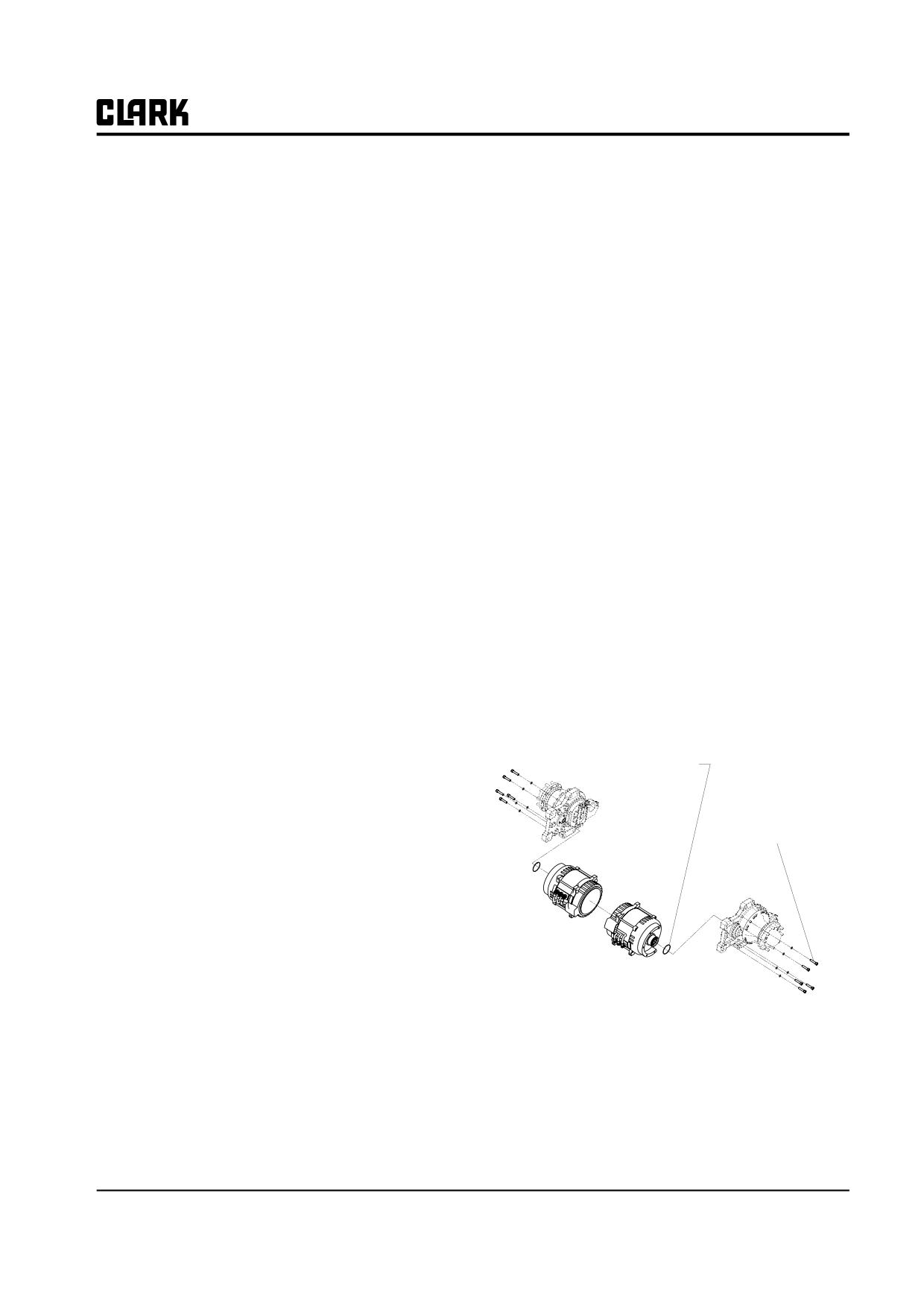
Remove bolts holding motor to axle. Have drain pan
• Turn the key switch OFF.
in place to catch axle oil.
• Disconnect battery from truck receptacle.
9.
Lower motor onto floor or through the top using a
• Discharge capacitors by connecting a 200 ohm 10
suitable chain hoist or come-a-long.
watt resistor between the positive and negative
10.
Reinstall in reverse order. Use new O-ring, coated
input post of the controller for 10 seconds.
with drive axle fluid.
11.
Check and fill drive axle oil as described in Group
Motor Cleanliness
20.
Electric motors should be kept clean at all times to prevent
NOTE
shorting, minimize wear, and optimize cooling.
When removing or installing cables to motor,
• Wipe off all dust, dirt, oil, water, etc., from outer
hold the terminal's lower nut with a wrench
surface of motor.
while turning the upper fastening nut with
another wrench.
• Remove any debris from cooling fan air vents and
around motor frame to prevent overheating.
Coat O-Ring with Transmission
• Air-clean (blow off) motors using clean, dry (mois-
Fluid Prior to Installation
ture-free) compressed air at 207 kPa (30 psi) maxi-
mum air pressure.
The presence of any oil on or near the motor could indi-
Torque to 70 - 75 N-M
(51 - 55 lb/ft)
cate either bad bearings or leaking hydraulic system.
Determine cause and repair problem before extensive
motor damage occurs.
Drive Motor Removal and Installation
1. Remove the battery from the truck.
2. Tilt the steering column fully forward and remove
the floor plate.
3. Remove all electrical cables from the drive motor.
Tag cable terminals to aid in reinstallation and posi-
tion the cable out of the way.
4. Remove the mast from the truck.
5. Remove the drive axle from the truck.
SM 765, Nov ’06
Drive Motor Overhaul • 16-2-1
Group 16, Electrical Motors
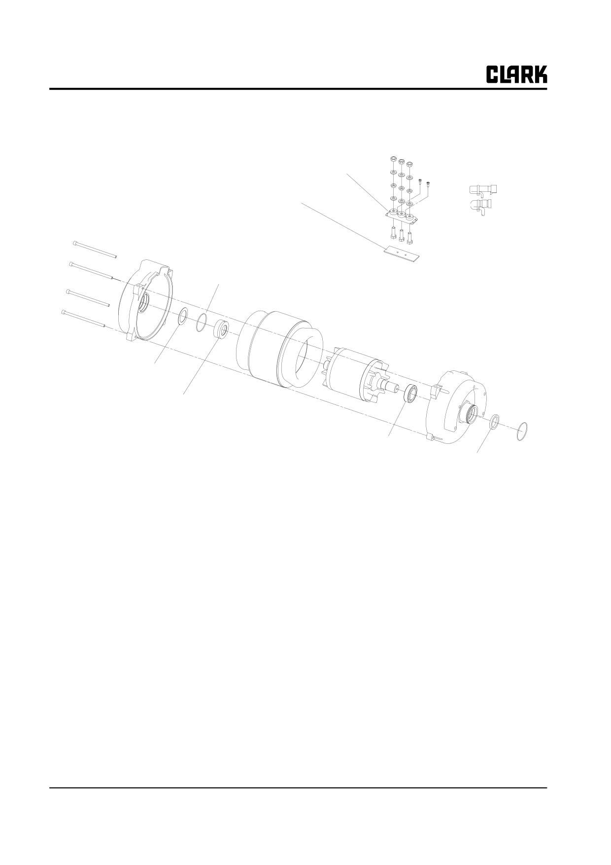
Terminal Block
Terminal Block
Mounting Bracket
Screw
Non-Drive End Frame
O-Ring
Stator
Rotor
Drive End Frame
Wave washer
Encoder Bearing
Ball Bearing
O-Ring
Shaft Seal
Ball Bearings
Encoder Bearing
Both ball bearings are maintenance free. If it becomes
The encoder bearing is used to communicate the motor
necessary to remove the bearings to repair the motor, they
speed to the controller.
should be replaced. In any case the seals (shaft oil seal and
NOTE
O-ring) must be replaced.
The encoder bearing is very sensitive to static
In general bearings should be replaced at approximately
electricity. If you are going to be working on
10,000 operating hours.
the encoder bearing you should have a
ground strap on to insure that the encoder
bearing does not get damaged.
16-2-2 • Drive Motor Overhaul
SM 765, Nov ’06
Group 16, Electrical Motors
• Insure that the encoder cables are installed cor-
Replacing Encoder Bearing
rectly and do not get pinched or touch the rotor.
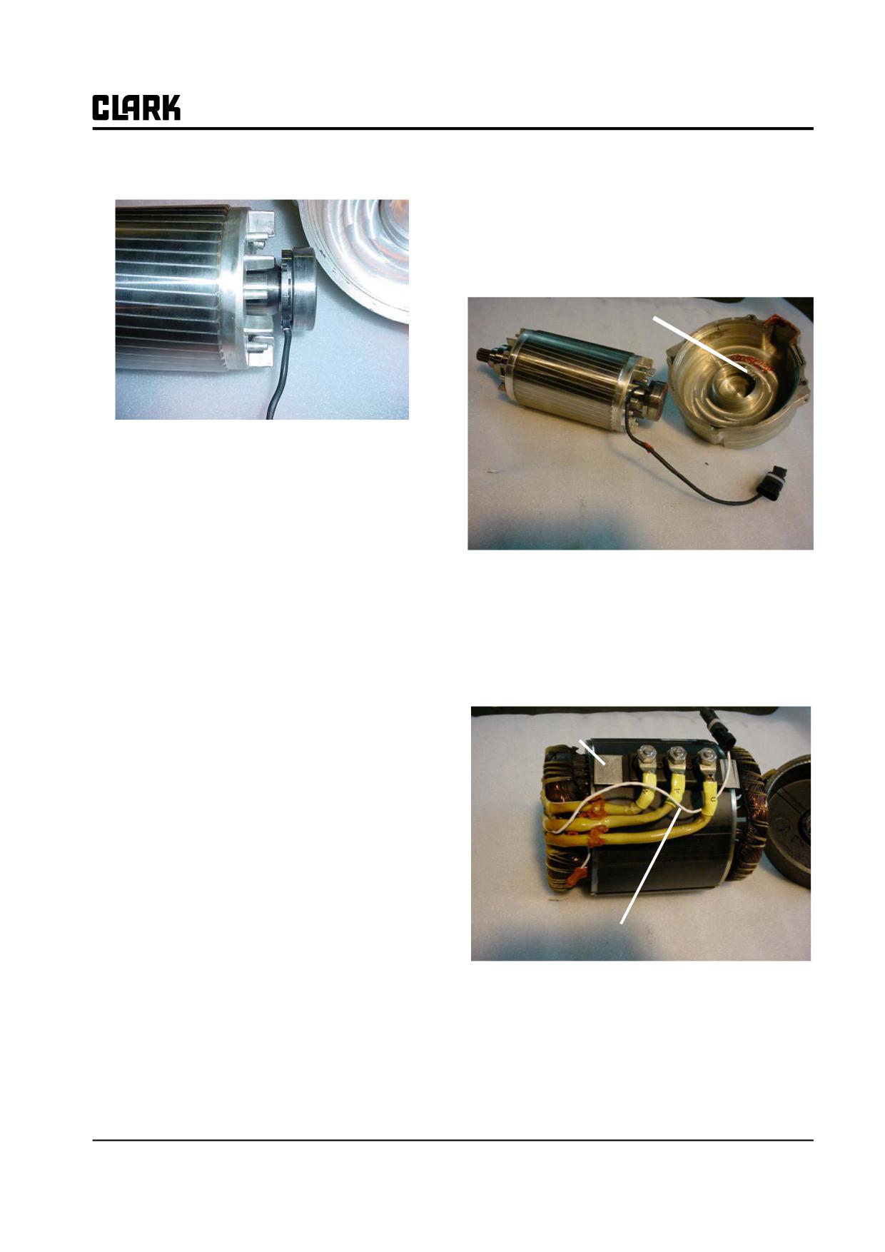
• Install the end housing carefully onto the encoder
bearing and press it on with a steady pressure. The
lead from the bearing must located in the notch in
the housing frame.
Notch for Lead
In general the encoder bearing should be replaced every
time the motor is disassembled.
To replace the encoder bearing:
• Turn key OFF.
• Set park brake.
• Install the rotor into the stator housing.
• Disconnect battery.
• Tie strap the encoder bearing lead to one of the
• Remove the drive motor (see page 1 of this sec-
motor leads to prevent it from being pulled and
tion).
contacting the rotor.
• Remove motor thru bolts.
• Install the drive end onto the motor making sure
• The silicone sealing the cables into the end frame
that the terminal block mounting bracket is aligned
will need to be loosened to allow removal of the
with the slots in both end frames.
end frame.
• Remove the non-drive end housing from motor.
Terminal Block
Mounting Bracket
• Remove rotor from motor.
• Use a gear puller to remove encoder bearing from
the rotor.
• Press new encoder bearing on to rotor at the inner
ring with a steady pressure. The inner ring of the
bearing must to be pressed against the shaft shoul-
der.
Motor Reassembly
Thermal Sensor Lead
NOTE
The encoder bearing is very sensitive to static
electricity. If you are going to be working on
• Install the motor through bolts and tighten.
the encoder bearing you should have a
ground strap on to insure that the encoder
• Fill the void around the drive motor leads with Sil-
bearing does not get damaged.
icone # 1758629.
• Reinstall the motor into the truck.
SM 765, Nov ’06
Drive Motor Overhaul • 16-2-3
NOTE :
Group 16, Electrical Motors
SM 765, Nov ’06
Group 16, Electrical Motors
Section 3
Pump Motor Overhaul
3. Have drain pan in place to catch axle oil. Remove
Inspection Procedure
the hydraulic pump from the motor (see group 29 for
Before performing these service procedures:
instructions).
• Park truck safely.
IMPORTANT
• Fully lower the upright.
The pump motor assembly weighs over 110
• Apply the park brake
pounds. A suitable lifting device may be
needed to help hold and then raise the motor
• Turn the key switch OFF.
from the truck.
• Disconnect battery from truck receptacle.
• Discharge capacitors by connecting a 200 ohm 10
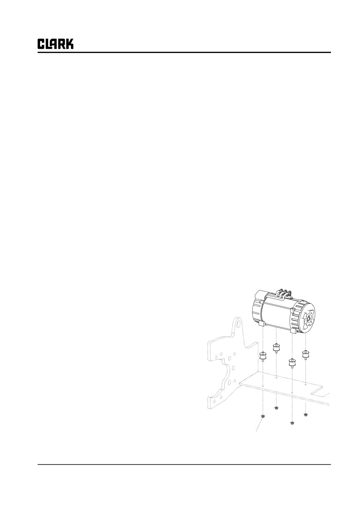
4. Remove the 4 nuts securing the pump motor mount-
watt resistor between the positive and negative
ing plate to the frame bottom.
input post of the controller for 10 seconds.
5. Lift the motor assembly and place it on a bench for
service.
Motor Cleanliness
6. Reinstall in reverse order.
Electric motors should be kept clean at all times to prevent
NOTE
shorting, minimize wear, and optimize cooling.
When removing or installing cables to motor,
• Wipe off all dust, dirt, oil, water, etc., from outer
hold the terminal's lower nut with a wrench
surface of motor.
while turning the upper fastening nut with
• Remove any debris from cooling fan air vents and
another wrench.
around motor frame to prevent overheating.
• Air-clean (blow off) motors using clean, dry
(moisture-free) compressed air at 207 kPa (30 psi)
maximum air pressure.
The presence of any oil on or near the motor could indi-
cate either bad bearings or leaking hydraulic system.
Determine cause and repair problem before extensive
motor damage occurs.
Pump Motor Removal and Installation
1. Tilt the steering column fully forward and remove
the floor plate.
2. Disconnect battery and remove all electrical cables
from the motor. Tag cable terminals to aid in rein-
stallation. Position cables out of the way of motor
removal.
Torque to 40 - 45 N.m
(29.5 - 33.2 Lbs.ft)
SM 765, Nov ’06
Pump Motor Overhaul • 16-3-1
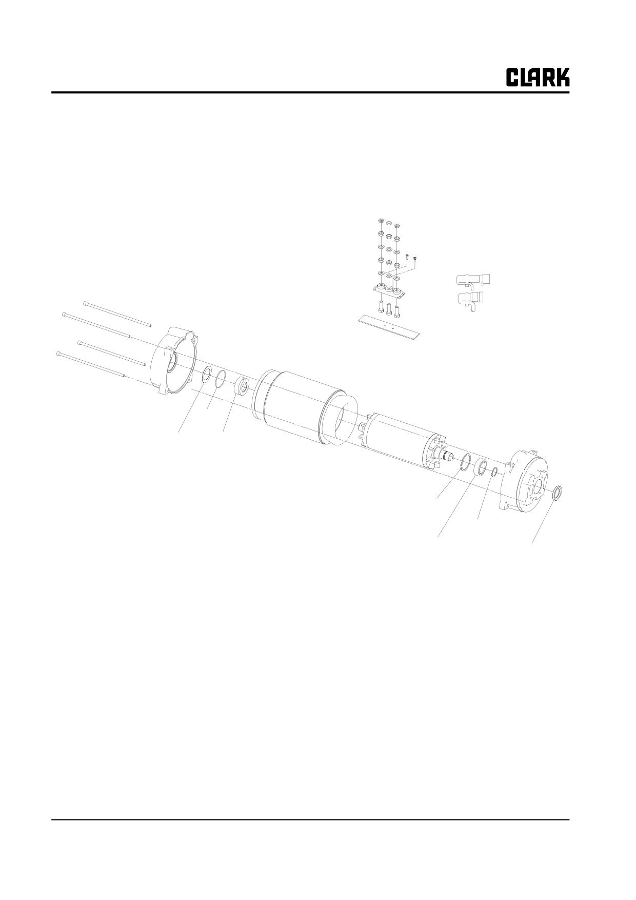
Group 16, Electrical Motors
Terminal Block
Terminal Block
Mounting Bracket
Screw
Non-Drive
End Frame
Stator
O-Ring
Rotor
Wave Washer
Encoder
Bearing
Drive End Frame
Snap Ring
Snap Ring
Ball Bearing
Shaft Seal
Pump Motor Exploded View
Ball Bearings
Encoder Bearing
The encoder bearing is used to communicate the motor
speed to the controller.
Both ball bearings are maintenance free. If it becomes
necessary to remove the bearings to repair the motor, they
NOTE
should be replaced. In any case the seals (shaft oil seal and
The encoder bearing is very sensitive to static
O-ring) must be replaced.
electricity. If you are going to be working on
the encoder bearing you should have a
In general bearings should be replaced at approximately
ground strap on to insure that the encoder
10,000 operating hours.
bearing does not get damaged.
16-3-2 • Pump Motor Overhaul
SM 765, Nov ’06
Group 16, Electrical Motors
Replacing Encoder Bearing
Motor Reassembly
In general the encoder bearing should be replaced every
• Press new encoder bearing on to rotor at the inner
time the motor is disassembled.
ring with a steady pressure. The inner ring of the
bearing must to be pressed against the shaft shoul-
der.
To replace the encoder bearing:
NOTE
• Turn key OFF.
The encoder bearing is very sensitive to static
• Set park brake.
electricity. If you are going to be working on
• Disconnect battery.
the encoder bearing you should have a
ground strap on to insure that the encoder
• Remove the pump motor (see page 2 of this sec-
bearing does not get damaged.
tion).
• Remove motor bolts.
• Insure that the encoder cables are installed cor-
• Loosen the silicone sealer around the cables at the
rectly and do not get pinched or touch the rotor.
end housing.
• Install the end housing carefully onto the encoder
• Remove the non-drive end housing from motor.
bearing and press it on with a steady pressure. The
• Remove rotor from motor.
lead from the bearing must located in the notch in
the housing frame.
• Use a gear puller to remove encoder bearing from
the rotor.
• Install the rotor into the stator housing.
• Tie strap the encoder bearing lead to one of the
motor leads to prevent it from being pulled and
contacting the rotor.
• Install the drive end onto the motor making sure
that the terminal block mounting bracket is aligned
with the slots in both end frames.
• Install the motor through bolts and tighten.
• Fill the void around the drive motor leads with Sil-
icone # 1758629.
• Install the fan and snap ring onto the shaft.
SM 765, Nov ’06
Pump Motor Overhaul • 16-3-3
NOTE :
Group 16, Electrical Motors
SM 765, Nov ’06
GROUP 17 ELECTRICAL CONTACTORS
GROUP 17
ELECTRICAL CONTACTORS
Contactors Specifications and Overhaul
Section 1
SM 765, Nov ’06
Group 17 ELECTRICAL CONTACTORS
NOTE :
Group 17 ELECTRICAL CONTACTORS
SM 765, Nov ’06
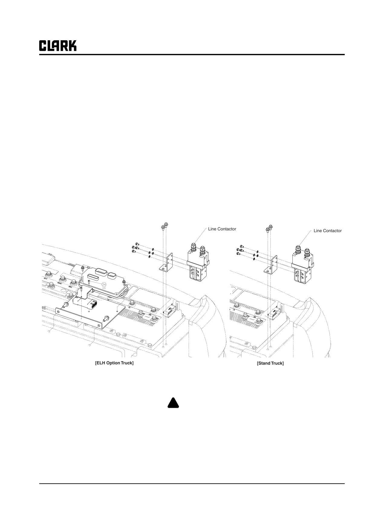
Group 17, Electrical Contactors
Section 1
Contactors Specifications and Overhaul
Specifications
Removal and Replacement
Standard Truck: One Drive Line Contactor, one Pump
1. Disconnect power cables from contactors. Move
Line Contactor. Mounting Fastener Torque: 8-10 N.m (71-
power cables out of the way.
88 in-lb).
2. Disconnect connecting bus bars from contacts.
3. Disconnect wiring from contactor coil terminals.
4. Remove mounting bolts and contactor assembly from
truck.
5. Reverse procedure for installation.
Overhaul
! WARNING
Disconnect battery before working on contactor tips.Before attempting to disassemble a con-
tactor to install a new contact set, carefully observe location and orientation of each part.
SM 765, Nov ’06
Contactors Specifications and Overhaul • 17-1-1
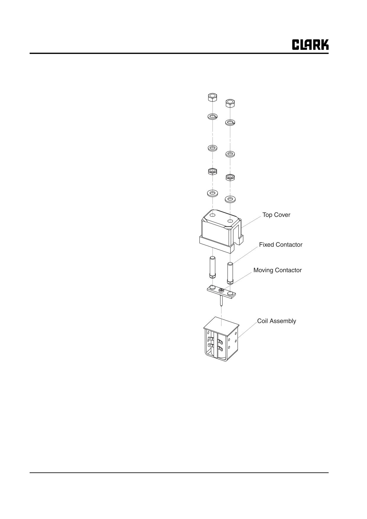
Group 17, Electrical Contactors
binding and that tips are in correct orienta-
CONTACTOR INSPECTION AND
tion and tips contact correct mating parts.
TIP REPLACEMENT
1.
Check armature and movable contacts for freedom of
movement by depressing movable arm with a screw-
driver or small rod. Check for any restrictions to
movement and for return of parts by action of spring.
2.
Inspect contact tips. Look for any worn or eroded
surfaces. Look for evidence of tip welding.
Inspect for evidence of any contaminants on tips
(paint, dirt, paper or cloth material, etc.) which
would impair operation.
Do not use sandpaper or file tips. Any damage must
be corrected by tip replacement.
Tips must be replaced before they wear through and
damage copper base.
To remove and replace contact tips, use following
3.
To replace tips on the contactors, loosen and remove
two cover mounting screws attaching it to coil frame.
(Observe position of positive (+) marking on cover).
Be careful not to lose return spring fitted under cover.
Remove locknut and lockwasher from contact studs
and remove contact studs from top cover. Inspect the
top cover to make sure it has not been overheated and
that the contact studs have not melted into the plastic.
Replace the studs with new.
Lift movable contact assembly off base. Remove
lock ring from armature shaft and remove moving
contact tips. Be careful not to disassemble or lose
other parts under contact tips on armature assembly.
Replace movable contacts with new and assemble
onto armature shaft. Make sure lock ring is fully
seated.
Assemble contactor by putting moving contact
assembly armature shaft into coil plunger with return
spring on top of armature shaft. Put top cover over
spring and install cover mounting screws. Be sure
return spring is in recess in top cover.
NOTE
When assembling top cover to base, make
sure it is installed with positive sign (+) mark-
ings located correctly. Use a bar or rod to
move contacts. Be sure movement is free of
17-1-2 • Contactors Specifications and Overhaul
SM 765, Nov ’06
GROUP 19 MOTOR CONTROLS
GROUP 19
MOTOR CONTROLS
Description
Section 1
Control Programming
Section 2
Control troubleshooting
Section 3
GEX Factory Control Settings
Section 4
SM 765, Sep ’06
Group 19 MOTOR CONTROLS,
NOTE :
Group 19 MOTOR CONTROLS,
SM 765, Sep ’06
Group 19, Motor Controls
Section 1
Description
The CLARK GEX uses a Dual AC controller to control both drive motors and a single AC controller
to control the single motor/pump combination which supplies flow to all hydraulic functions and
steering.
Traction Control and Motors
uses this information to increase motor speed in propor-
tion to the distance stroked, providing only the desired
The dual AC traction control consists of two motor con-
flow rate. Tilt and aux switches mounted on the hydraulic
trols mounted to a single heat-sink plate and enclosed by a
valve provide unique inputs to the control. The speed of
single cover. The right portion of the control is reference
each function can be programmed independently so that
to as the "slave" control and operates the left drive motor.
only the required flow rate is produced, minimizing power
The left portion of the control is referred to as the "mas-
losses. When the key is in the "ON" position and a direc-
ter" control and operates the right drive motor. The con-
tion is selected, the control will operate the motor at a
trol receives inputs from the speed control (accelerator)
fixed rpm (roughly 500~600 rpm). This provides adequate
pedal, steer tire position sensor (steer pot), direction
flow for the steering function. If the control receives an
switches, foot brake switch, motor encoders, motor ther-
input from the lift potentiometer, tilt or aux switches, then
mistors and other miscellaneous switches. The control is
it will ramp up the motor speed to match the desired
able to proportional reduce the speed of the inside tire
speed. Once the request is removed the motor speed will
when the truck is in a turn, based on the steer angle input
return to the fixed level. As with the traction control and
from the steer sensor. Once the steer angle exceeds a cer-
motors, the lift/steer control and motor have thermistors
tain value, the inside wheel will start to reverse. The
for thermal protection and the motor has a built-in encoder
speed of the vehicle is controlled by the accelerator con-
for speed feedback.
trol pedal. For a given pedal position the control will
maintain a set speed, as determined by control parameter
settings. These settings are adjustable to meet your cus-
tomer's needs. One feature that is new to the GEX is
"release braking". This feature will apply a regenerative
braking force every time the driver lifts up off the acceler-
ator pedal. The final travel speed will be determined by
the new pedal position. The control receives motor speed
feedback from the motor encoders which allow for precise
speed regulation. Every motor also has a built-in ther-
mistor which constantly monitors the winding tempera-
ture and reports this information to the control. Should it
sense that the motor is approaching the temperature limit,
the control will cutback motor current until the tempera-
ture decreases. Since it is cutting back current and not
voltage, the top end speed will not be effected, unless on a
grade. Each control also has built-in thermal protection
that will reduce output current should the control
approach the thermal limit.
Lift/Steer Control and Motor
A single motor/pump combination is used for both
hydraulic functions and steering. The motor is controlled
by a dedicated controller. The lift lever is equipped with a
linear potentiometer that measures the distance the lever is
stroked and provides this input to the control. The control
SM 765, Sep ’06
Description • 19-1-1
Group 19, Motor Controls
Operational Features
Speed Limit
Parameters MAX SPEED FORWARD and MAX SPEED
Creep Speed
BACKWARD allow for the adjustment maximum speed
that the vehicle can travel in each direction. The maxi-
Parameters THROTTLE X POINT and THROTTLE Y
mum speed is adjustable from 0 Hz to 140 Hz in 1 Hz
POINT control how the truck reacts when you first push
increments.
on the accelerator. Increasing THROTTLE X POINT will
give you more pedal stroke with less speed at the begin-
ning of the stroke. Increasing THROTTLE Y POINT will
Example: 140 Hz = approx. 11.1 mph empty
give more speed with less pedal stroke. See Chart below.
78 Hz = approx. 6.2 mph empty
SPEED f(Hz)
Stop on Ramp
When this feature is ON it lets the vehicle electrically hold
MAX SPEED
on an incline. Time is adjustable with AUXILIARY
TIME parameter.
When this feature is OFF the vehicle uses regen braking to
stop on an incline. Once the vehicle has stopped it will
TROTTLE Y
POINT
hold for 1 second then continue to creep down the incline
FREQ. CREEP
at approx. 1 mph. The vehicle can continue up the ramp at
V
any time without hesitation.
VACC
TROTTLE 0
TROTTLE X
VACC
MIN
ZONE
POINT
MAX
Steering Time Delay
This feature uses the AUXILIARY TIME in the pump
Control acceleration
control to delay turn off time when the directional lever is
returned to neutral. This parameter is adjustable from 0 to
Parameter ACCELERATION DELAY allows the adjust-
20 seconds of delay.
ment of the time it takes to accelerate a stop to full speed.
See parameter-programming chart later in this manual.
Static Return to Off (SRO)
Regenerative braking
This feature requires the operator to return the directional
lever to the neutral position anytime they leave the vehicle
Parameter INVERSION BRAKING allows for the adjust-
and return. If the parking brake, seat switch or key switch
ment of the amount of time that it takes to stop the vehicle
is opened, the control shuts down and can not be restarted
when changing from one direction to the other. See
parameter-programming chart later in this manual.
(The dash display will show a -79 fault code) until the
directional lever is returned to neutral. A time delay of
approximately 2 seconds is built in to allow momentary
Accelerator Pedal Position Plug braking
opening of the parking brake or seat switch.
Parameter RELEASE BRAKING allows for the adjust-
ment of the amount of time that it takes to stop the vehicle
Thermal Protector
when you remove your foot from the accelerator. See
parameter-programming chart later in this manual.
Each controller has an internal thermal protector on the
heat sink. The controllers will reduce the output current
to 50% of the set current when the heat sink temperature
Brake Pedal Regen Braking
reaches 75°C. The dash will display the following codes
Parameter PEDAL BRAKING allows for the adjustments
depending on which controller in over temperature, (Mas-
of the amount of regen braking you receive when you
ter -61 code, Slave -140 code, and Pump -203 code).
apply the service brake. See parameter-programming
chart later in this manual.
19-1-2 • Description
SM 765, Sep ’06
Group 19, Motor Controls
Standard Fault Codes
NOTE
The control has over 75 fault codes assist the service tech-
nicians and operators in the trouble shooting the vehicle.
The Handset instructions and Troubleshoot-
If mis-operation of the vehicle occurs, a fault code will be
ing can be found in Group 19, Section 3 of
displayed on the Dash Display of the vehicle, or by plug-
this manual.
ging the handset into the "B: plug of the master controller
and reading the fault code.
Protection Features
With the fault code number, follow the procedures out-
lined in Group 19, Section 03 ,"Fault Codes", section to
Reverse Battery Polarity:
determine the problem and a solution.
The MAIN CONTACTOR is there to protect the control-
ler against reverse battery polarity and for safety reasons.
Stored Fault Codes
This feature records the last 5 fault codes in controller.
Connection Errors:
The last 5 fault codes can be accessed through the alarm
log using a handset, or a laptop computer with the PcCon-
All inputs are protected against connection errors.
sole software and adapter cable. The faults are stored with
the hour meter reading when the fault first happened, the
Thermal Protection:
number of time the fault has happened, and the tempera-
ture the first time the fault happened.
If the controller temperature exceeds 80° C, the maximum
current is reduced in proportion to the thermal increase.
Hour Meter Readings
The temperature can never exceed 100° C.
When the traveling speed is less than 0.5km/h, it displays
External Agents:
the accumulated operating hour.
The controller is protected against dust and the spray of
Battery Discharge Indication (BDI)
liquid to the degree of protection meeting IP54.
Provides accurate battery state of charge information to
Protection Against Uncontrolled Movement:
the vehicle operator, Features and Functions:
• Displays 100 to 0 percent charge in 10% incre-
The main contactor will not close if:
ments.
- The power unit is not functioning
•
Lift Circuit is disabled at 10% discharge
- The controller is not functioning perfectly.
- The output of the accelerator does not fall
below the minimum voltage value stored, with
Handset
1V added
This is a multifunctional tool used with the AC controls.
- Running microswitch is in closed position.
The handset (Clark part #8033636) has a display and a
key board for data entry.
Low Battery Charge:
When the battery charge is low, -66 Code, the maximum
Features and functions:
current is reduced to half the maximum current pro-
• Monitor existing fault codes for both traction and
grammed.
pump controls.
• Monitor hour meter readings on traction and pump
Protection against accidental startup:
controls.
A precise sequence of operations is necessary before the
• Monitor or adjust the control functions
control will start (SRO). Startup cannot occur if the
• Use as a tester to monitor input and output infor-
mation.
SM 765, Sep ’06
Description • 19-1-3
Group 19, Motor Controls
sequence is not followed completely. (Request for drive,
potentiometer signal acquisition is carried out using the
must be made after closing the key switch).
handset. This enables adjustment of the minimum and
maximum useful signal level (PROGRAM VACC func-
tion), in either direction. This function is unique when it is
Capacitor Charge:
necessary to compensate for asymmetry with the mechan-
The controllers can hold an electrical charge for several
ical elements associated with the Potentiometer. Espe-
seconds, due to the power capacitor bank. A discharge
cially relating to minimum level. The sequence of
resistance is built in the controller, which ensures capaci-
procedure is described later in this manual.
tor discharge to a safe voltage in about one minute, after
the key is switched off. If it is necessary to work on the
Analog control unit
controller before that time, discharge the capacitors as
described below.
Connection C25 (PTHERMR) and C24 (NTHERMR) are
used for the right motor thermal sensor. Connection C35
(PTHERML) and C34 (NTHERML) are used for the Left
Discharging Controller Capacitors
motor thermal sensor. Sensors are analog.
It is necessary to discharge the capacitors before you work
on the controller. To discharge the capacitors, disconnect
Speed Feedback
the battery at the battery receptacle, connect a 200 ohm 10
watt resistor between the positive and negative input post
The traction motors control is based upon the motor speed
of the controller for 10 seconds.
feed back. The speed transducer is an incremental
encoder, with two phases shifted at 90°. The encoder is
supplied with +12V from the control panel.
Communications with CLARK Dash:
The traction controller communicates by CANBUS to
Steer Angle Transducer
CLARK dash. The dash shows Battery State of charge,
Hourmeter and fault code if a fault occurs.
Angular position of steered wheels in transduced to an
electric information (voltage) by means of a potentiome-
ter, with following characteristics:
Microswitches:
- Positive supply: 12V ± 2V
The micro switches must have a contact resistance lower
- Voltage potentiometer : 1V~9V
than 0.1ohm and a leakage current lower than 100 micro
- Netural : 5V
amps.
- Potentiometer is installed in a way that in the
When full load is connected, the voltage between the key
zero position (straight wheels), pot output volt-
switch contacts must be lower than 0.1 volt.
age is in the middle of the electric range corre-
sponding to a full left-to-right transition of
The micro switches send a voltage signal to the micropro-
steer wheels;
cessor when a function is requested (for example: running
- The potentiometer is installed in a way that,
request) is made.
when the truck turns right, pot voltage
increases;
Accelerator Unit:
- Use "SET STEER MIN" and "SET STEER
MAX" functions of the handset to record the
The accelerator unit consists of a potentiometer in 3 wire
extremes (minimum and maximum) of the
configuration.
potentiometer range;
- Use "SET STEER 0-POS" function of the
CPOT (C21) signal.
handset to record the pot output when the steer
EN ACC (C8) is the accelerator enable. It is fed with
wheels are straight.
+Batt from the key switch.
NPOT (C20) is the accelerator negative supply. This out-
put is feed back to the microprocessor A/D converter to
test the continuity of the accelerator unit circuit (test of
pot wire disconnection). The procedure for automatic
19-1-4 • Description
SM 765, Sep ’06
Group 19, Motor Controls
Steering Table
The relationship between the two motors speed changes as
a function of the steering angle.
The steering angle information comes from the transducer
(potentiometer). As the steer wheel is turned, the inside
motor will slow and than finally reverse direction to help
the truck turn sharply.
SM 765, Sep ’06
Description • 19-1-5
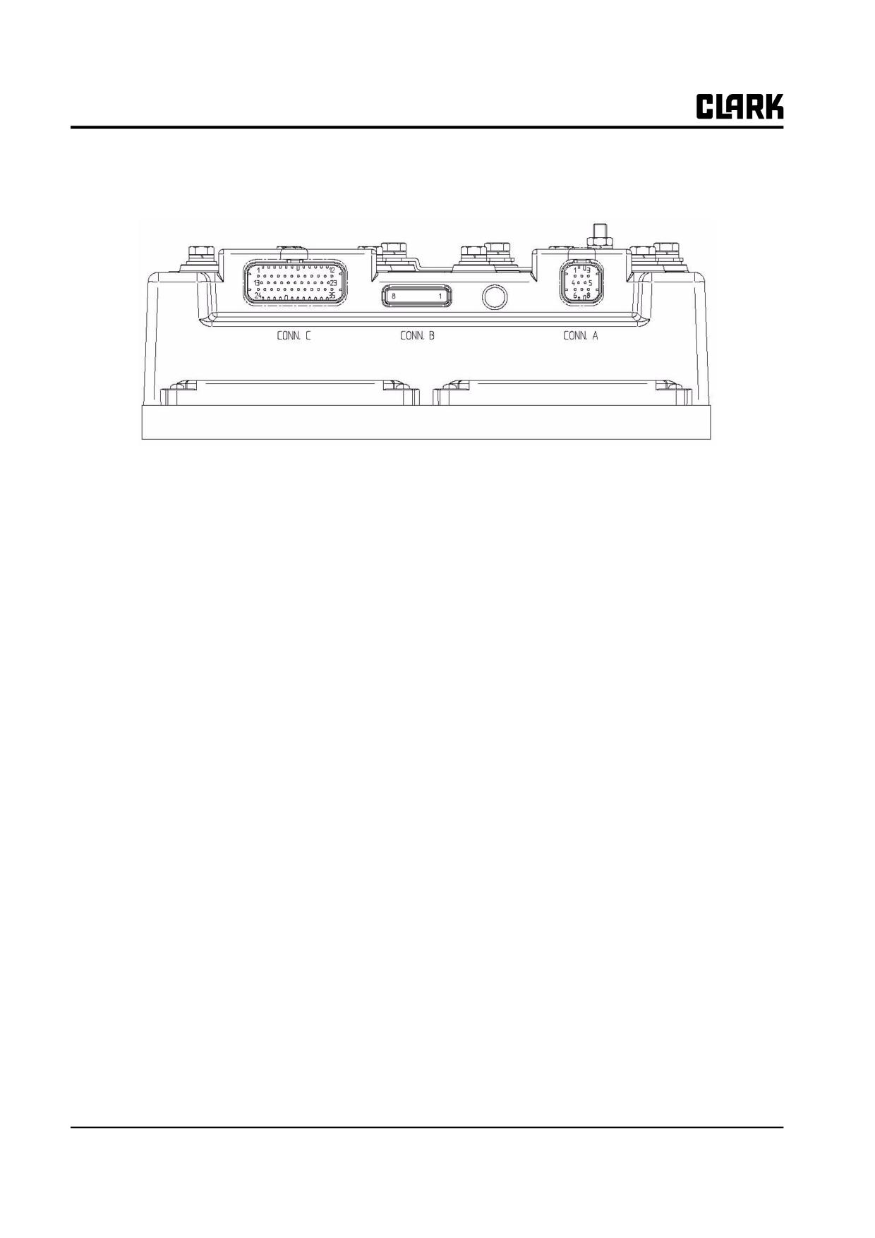
Group 19, Motor Controls
Description of Connectors - DualAC2(Power)
A1
CAN H
High level CANBUS
A2
CANT H
CANBUS termination output, 120 ohm internally connected to CAN_H. Connect to
CAN_L_OUT to insert termination.
A3
CAN_POS
Positive of CAN circuit; to be used in case of optoisolated CANBUS
A4
CAN_L_OUT
Low level CANBUS: to be used as repetition for CAN_L line or to be connected to CANT_H
to insert termination resistance
A5
CANT_L
CANBUS termination output, 120 ohm internally connected to
CAN_L. CAN Connect to CAN_H_OUT to insert the termination.
A6
CAN_L
Low level CANBUS.
A7
CAN_H_OUT
High level CANBUS: to be used as repetition for CAN_H line or to be connected CANT_L to
insert termination resistance
A8
CAN_NEG
Negative of CAN circuit, to be used in case of optoisolated
CANBUS
B1
PCLRRXD
Positive serial reception.
B2
NCLRRXD
Negative serial reception.
B3
PCLRTXD
Positive serial transmission.
B4
NCLRTXD
Negative serial transmission
B5
GND
Negative handset power
B6
+12
Positive handset power
B7
FLASH
B8
FLASH
C1
PENC_R
Positive of the right motor encoder power supply (+12V).
C2
NENC_R
Negative of the right motor encoder power supply
C3
KEY
Connected to +Batt through a micro switch and a 10A fuse in series
C4
CM
Common of FW / REV / HB / PB / SEAT / ENABLE micro switches
C5
Seat
Seat presence input; active high.
C6
FORWARD
Forward direction request input; active high.
C7
REVERSE
Reverse direction request input; active high.
19-1-6 • Description
SM 765, Sep ’06
Group 19, Motor Controls
C8
ENABLE
Traction request input; active high.
C9
PB
Pedal brake request input; active high.
C10
SR / HB
Speed reduction or hand brake input; active low (micro switch open).
C11
PENC_L
Positive of the left motor encoder power supply (+12V).
C12
NENC_L
Negative of the left motor encoder power supply
C13
PHA_R
Right motor encoder phase A.
C14
PHB_R
Right motor encoder phase B.
C15
NPOTST
Negative of steering potentiometer (-Batt)
C16
PPOTST
Positive of steering potentiometer (+5V)
C17
CPOTST
Steering potentiometer wiper signal.
C18
CPOTB
Brake potentiometer wiper signal.
C19
NPOTB
-Batt.
C20
NPOT
Negative of traction accelerator (test for wire disconnection)
C21
CPOT
Traction potentiometer wiper signal.
C22
PHA_L
Left motor encoder phase A.
C23
PHB_L
Left motor encoder phase B.
C24
NTHERM_R
Negative of right traction motor temperature sensor.
C25
PTHERM_R
Right traction motor temperature signal.
C26
NLC
Output of main contactor coil driver (drives to -Batt)
C27
PLC
Positive of main contactor coil.
C28
NBRAKE
Output of electric brake coil (drives to -Batt, Maximum current 3A)
C29
PBRAKE
Positive of electromechanical brake coil.
C30
PAU
Xpositive of auxiliary load.
C31
NAUX
Output of auxiliary load driver (drives to _Batt).
C32
-BATT
C33
PPOT
Traction potentiometer positive, 5V output, use load > 1K omh.
C34
NTHERM_L
Negative of left traction motor temperature sensor.
C35
PTHERM_L
Left traction motor temperature sensor.
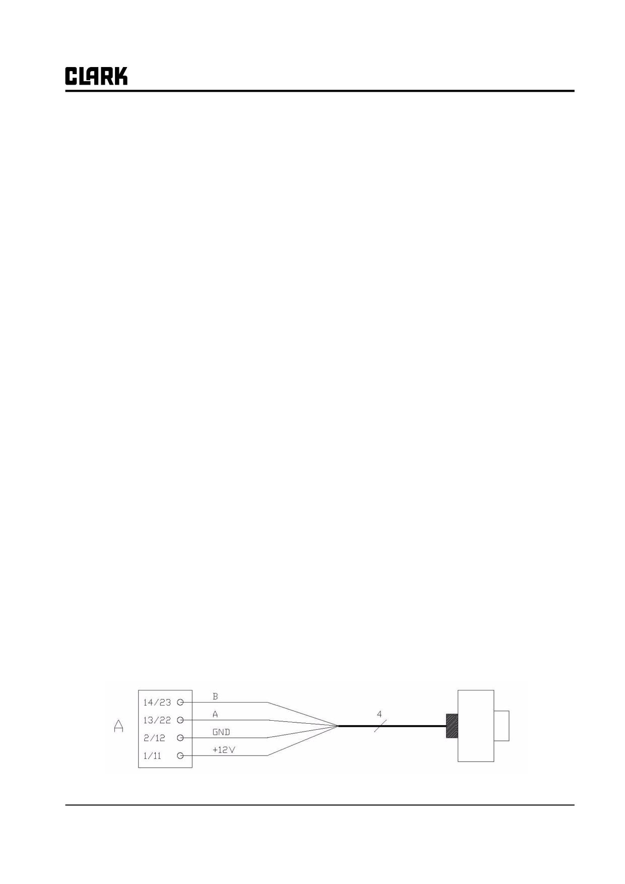
Encoder Installation
In order to control the AC motors with the ZAPI controller an incremental encoder is installed with 2 phases shifted at
90°. The encoder power supply is 12V
C11/C1
+12V
Positive of encoder power supply.
C12/C2
GND
Negative of encoder power supply.
C22/C13
A:
Phase A of the encoder
C23/C14
B:
Phase B of the encoder
Connection of encoder with open collector output; +12V power supply.
SM 765, Sep ’06
Description • 19-1-7
Group 19, Motor Controls
The encoder power supply voltage and output electronic
has to be communicated to ZAPI in order to correctly set
the selection jumper in the controller.
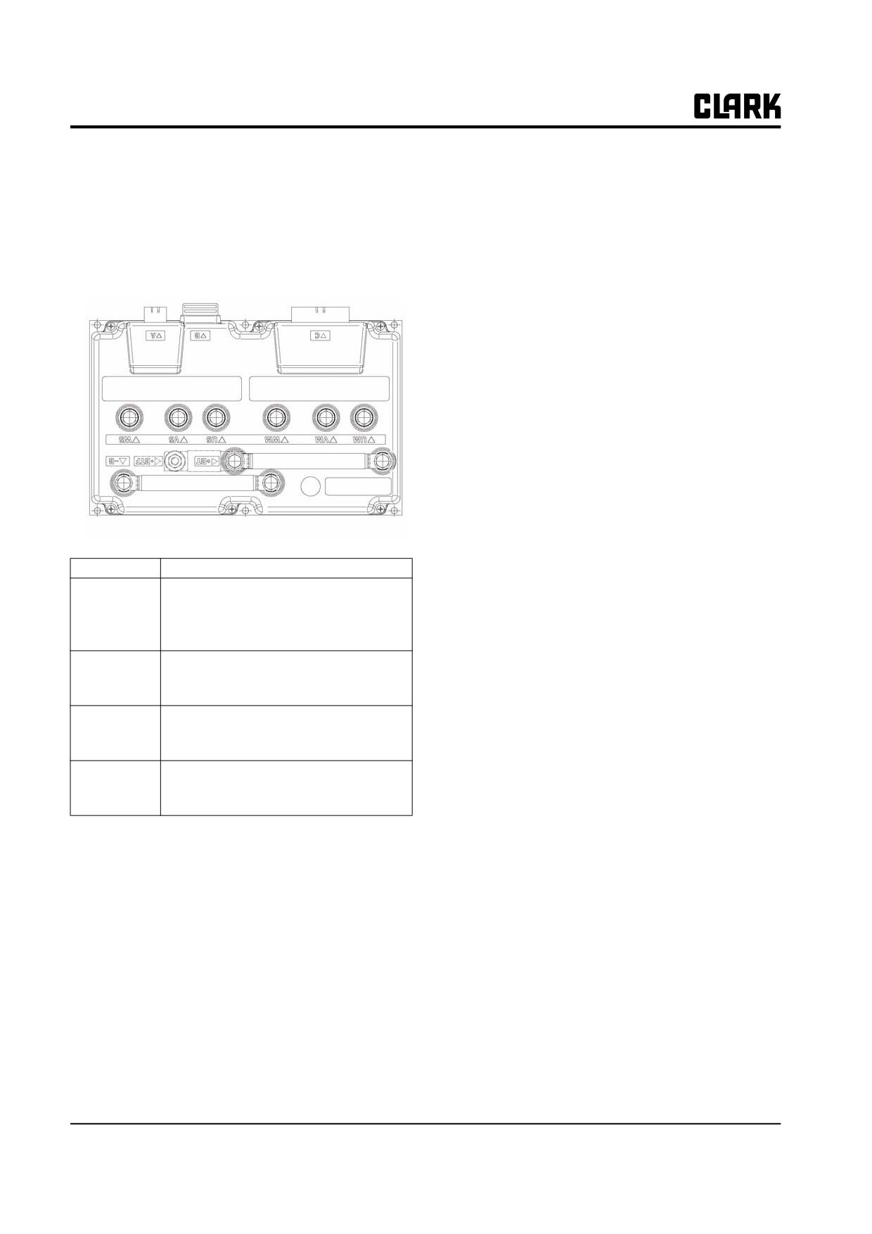
Description of Power Connections
-B
Negative of the battery
+BT
Positive of the battery; if the power fuse is
not present,positive cable coming from
the Line contactor must be connected to
this power connection
+BTF
Positive of battery before power fuse,
must be connected to positive cable com-
ing from line contactor.
Um: Vm; Wm
Connection bars for the three phases of
the right motor; follow this sequence and
the indication on the motor.
Us, Vs, Ws
Connection bars for the three phases of
the left motor; follow this sequence and
the indication on the motor.
19-1-8 • Description
SM 765, Sep ’06
Group 19, Motor Controls
Description of Connections - Hydraulic AC3
A1
CPOT
Accelerator potentiometer wiper.
A2
PPOT
Potentiometer positive: 10V output; keep load > 1KW.
A3
NPOT
Negative of accelerator unit, tested for wire disconnection diagnosis.
A4
CM
Common of LIFT ENABLE / 1st SPEED / 2nd SPEED / 3rd SPEED / 4th SPEED / HYDRO /
SR microswitches.
A5
LIFT ENABLE
Input for potentiometer lifting enable input; it is active HIGH.
A6
1st SPEED
Input for first speed request; it is active HIGH..
A7
3rd SPEED
Input for third speed request; it is active HIGH
A8
AN.IN
Free analog input.
A9
PPOT
Potentiometer positive: 10V output; keep load > 1KW.
A10
-BATT
-Batt.
A11
-BATT
-Batt.
A12
HYDRO REQ
Input for hydraulic steering request. Active high.
A13
SR
Speed reduction input. Active low (switch opened).
A14
DIG.IN
This is a digital input, free for customer request.
B1
KEY
Connected to the power supply through a microswitch (CH) with a
10A fuse in series.
B2
PAUX
Positive of the auxiliary output.
B3
PHYDRO
Positive for the hydraulic steering contactor.
B4
4th SPEED
Input for fourth speed request; it is active HIGH.
B5
SAFETY
If not connected to -Batt the MC coil power output will be disabled.
Can also be used as a general purpose input.
B6
PTHERM
Input for motor temperature sensor.
B7
CM
Common of LIFT ENABLE / 1st SPEED / 2nd SPEED / 3rd SPEED / 4th SPEED / HYDRO /
SR microswitches.
B8
NAUX
This output can be used for drive the main contactor coil (single pump configuration) or to drive
an auxiliary load (combi configuration)
B10
NHYDRO
Output for driving an hydraulic steering contactor; drives the load to -Batt. Maximum current:
3A.
B11
2nd SPEED
Input for second speed request; it is active HIGH.
B11
GND
-Batt.
B12
NTHERM
-Batt.
C1
CAN-L
Low level CAN-BUS voltage I/O.
SM 765, Sep ’06
Description • 19-1-9
Group 19, Motor Controls
C2
CAN-L-OUT
Low level CAN-BUS voltage I/O.
C3
CAN-H
High level CAN-BUS voltage I/O.
C4
CAN-H-OUT
High level CAN-BUS voltage I/O.
D1
-BATT
-Batt.
D2
MODE
This input allows the customer to select the software for traction or
lifting application.
Configuration:
MODE: Open (not connected)
Traction inverter
MODE: Close (connected with A5)
Pump inverter
E1~E6
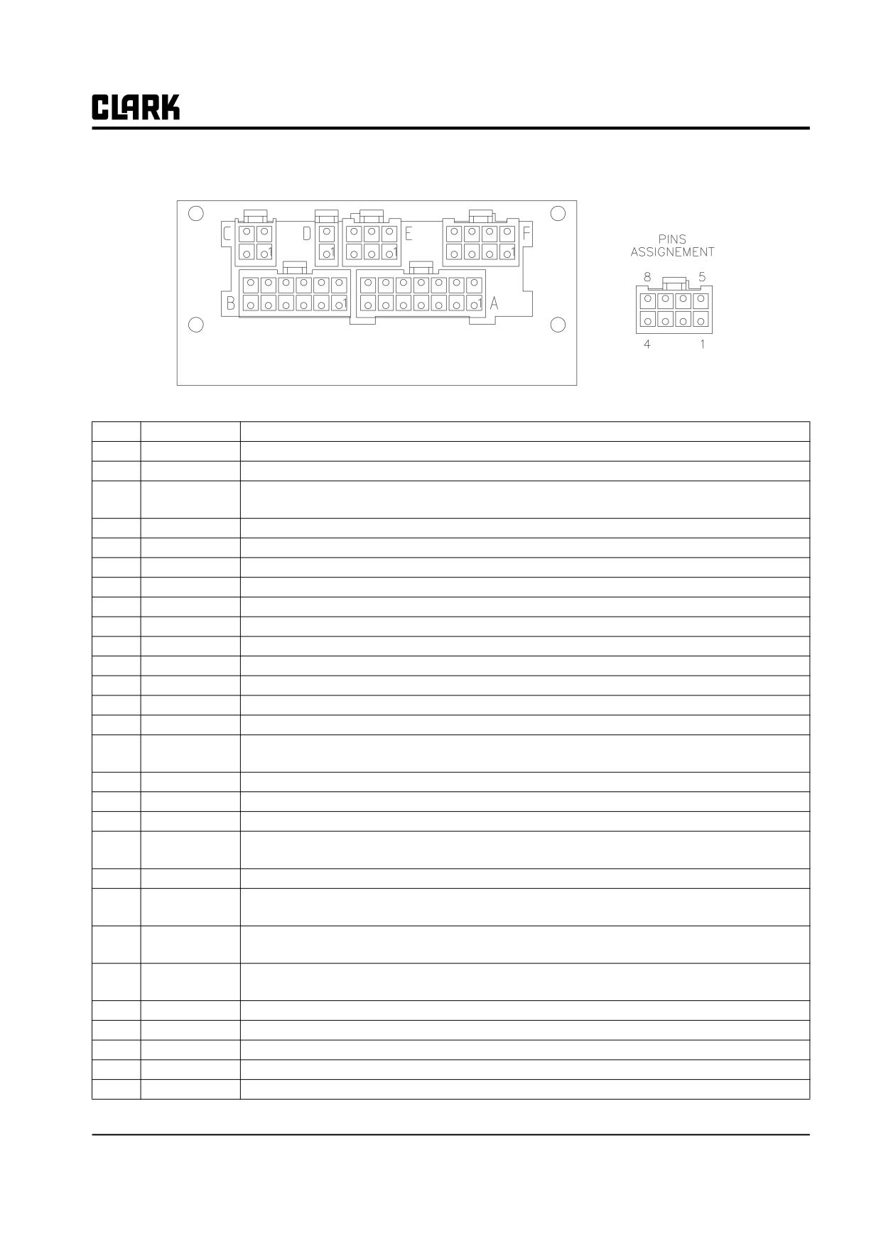
Incremental ENCODER connector (see chapter 3.6).
F1
PCLRXD
Positive serial reception.
F2
NCLRXD
Negative serial reception.
F3
PCLTXD
Positive serial transmission.
F4
NCLTXD
Negative serial transmission.
F5
GND
Negative console power supply.
F6
+12
Positive console power supply.
F7
FLASH
Must be connected to F8 for the Flash memory programming (if used).
F8
FLASH
Must be connected to F7 for the Flash memory programming (if used).
19-1-10 • Description
SM 765, Sep ’06
Group 19, Motor Controls
Section 2
Control Programming
Programming & Adjustments Using ZAPI Handset
Adjustments via Handset
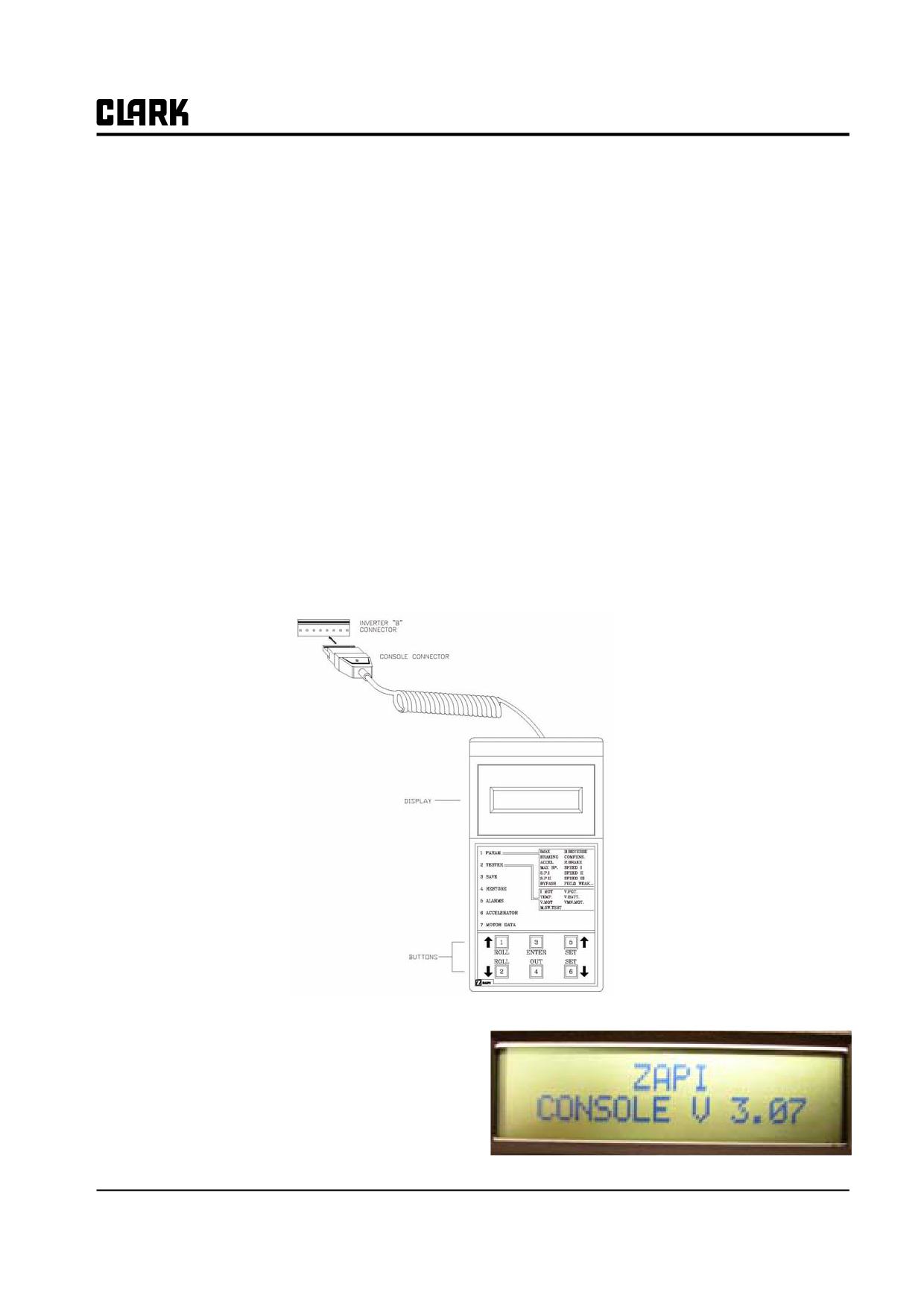
Adjustments of parameters and changes to the controller's configuration are made using the digital Handset. The Handset
is connected to the "B: connector of the controller.
Start with the battery disconnected at the battery receptacle, key switch in the OFF position.
Disconnect the dash display harness from the Master Control and connect the handset cord into this "B" connector.
Plug in the battery and turn the key switch ON.
Description of Handset & Connections
Digital Handsets used to communicate with the AC Controllers must be fitted with EPROM CK ULTRA, minimum
"Release Number 3.07, CLARK part number 8033636.
The Handset “Release Number” will be displayed on the
Handset display momentarily when the key switch is first
turned ON.
SM 765, Sep ’06
Control Programming • 19-2-1
Group 19, Motor Controls
The Handset display will than show a screen simular to the one shown below.
DA2M2BGCPE CK 0.13
80V 280A 00000
As shown in this Example; the “M” in DA2M2BGCPE, indicates the the Handset is now monitoring the Master control.
The slave control is represented with a :”S”, and the Pump control would be indicated with a “P”.
The last 6 digits of the top line in the example above indicate the current software revision loaded into the Master control.
The CK indicates CLARK and the 0.13 is the software revision level.
The bottom line on the display indicates the Battery Voltage and the current level that has been set and the current internal
hour meter reading of the control.
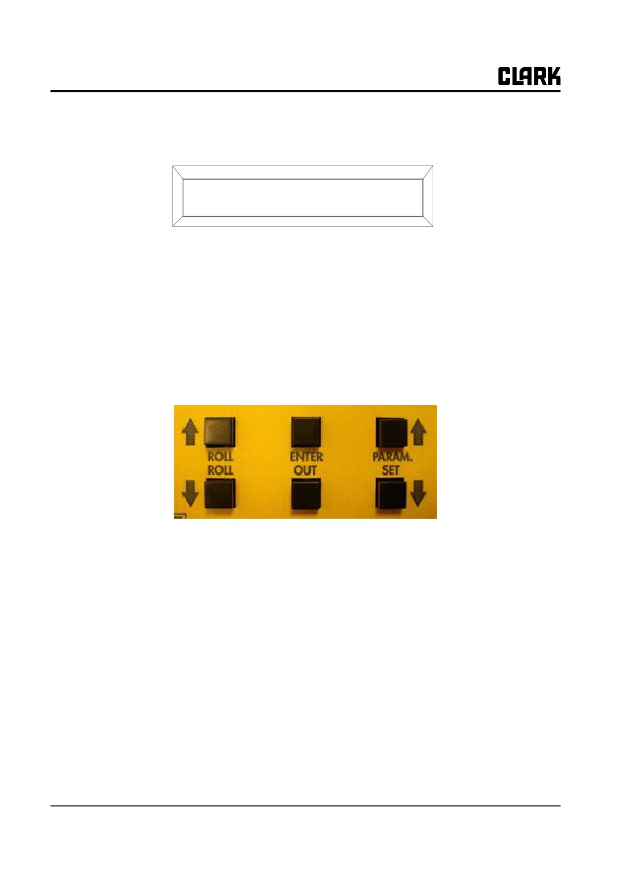
At the bottom of the Handset there are 6 push buttons used to navigate to a different control (Master, Slave or Pump), or to
navigate through the control functions and to make changes to the paramaters.
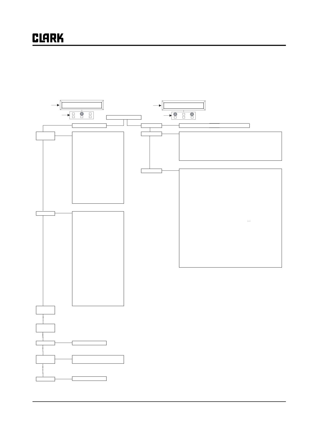
A flow chart of the Handset functions is shown on the following page.
The Handset is used to make adjustments to the parameters, used to view test functions within the electrical system of the
truck and to view the alarms (fault codes) that are present or stored in the memory of the controls.
See Group 19, Section 4 for GEX Factory Control Settings
19-2-2 • Control Programming
SM 765, Sep ’06
Group 19, Motor Controls
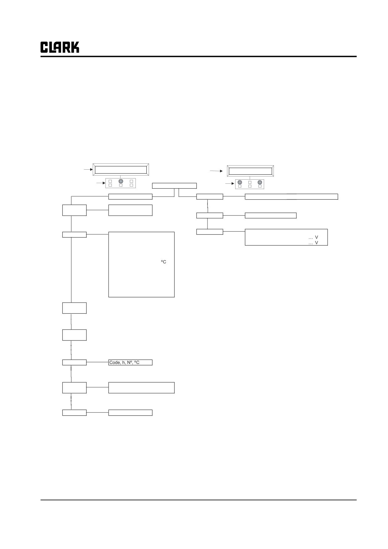
Gex Handset
Master Control Configuration
DA2M2BGCPE CK 0.13
DA2M2BGCPE CK 0.13
DISPLAY
80V 280A 00000
DISPLAY
80V 280A 00000
KEYBOARD
KEYBOARD
HEADING
Enter
Main Menu
Set Model
Connected to 3 (Master), 4 (Slave), 5 (Pump)
Enter
Parameter
Enter
Acceleration Delay
0-9
Set Options
Hour Meter
Running / Key On
Change
Release Braking
0-9
Battery Check
On/Off
Inverse Braking
0-9
Hydraulic Key On
On/Off
Pedal Braking
0-9
Stop On Ramp
On/Off
Speed Limit Braking
0-9
Roll
Aux Input #1
Exclusive Hyd / Option #1 / Option #2
Brake Cutback
0-9
Up
Pedal Braking
Analog / Digital / None
Roll
Max Speed Forward
Hz
Steer Table
Option #1 / Option #2
Up
Max Speed Reverse
Hz
Curve Cutback
%
Enter
Frequency Creep
Hz
Adjustments
Set Pot Brake Minimum
... V
Maximum Current
0-9
Set Pot Brake Max
... V
Auxilary Time
Sec
Set Battery Type
80V
Seat Micro Delay
Sec
Adjust Battery
... V
Acc Smooth
Sec
Max Steer Right
... V
Inv Smooth
Sec
Max Steer Left
... V
Stop Smooth
Hz
Set Steer 0-Position
... V
Idle Time
Min
Set Steer Right
...”
Set Steer Left
...”
Throttle 0 Zone
...%
Enter
Throttle Y Zone
...%
Tester
Motor Voltage
%
Throttle X Zone
...%
Frequency
Hz
Adjustment #04
”C
Encoder
Hz
Adjustment #01 (Display)
0-9
Slip Value
Hz
Adjustment #02 (Shut Down)
0-9
Current RMS
A
Main Contactor Voltage
... V
Temperature
”C
Aux Output Voltage
... V
Roll
Temperature #1
”C
Up
Temperature #2
”C
Maintenance Done
On/Off
Maintenance
None / Opt #1 / Opt #2
Accelerator
V
1 X 10,000 Hours
0-6
Steer Angle
...”
1 X 1,000 Hours
0-9
Brake Pedal Pot
%
1 X 100 Hours
0-9
Inner Wheel Cutback
%
Seat Switch
On/Off
1 X 10 Hours
0-9
1 X 100 Hours
0-9
Forward Switch
V
Reverse Switch
V
Enable Switch
On/Off
Brake Switch
On/Off
Cutback Switch
On/Off
Exclusive Hydraulics
On/Off
Hand Brake
On/Off
Voltage Booster
%
Battery Voltage
V
Battery Charge
%
Save
Parameter
Roll
Up
Restore
Parameter
Roll
Up
Enter
Alarms
Code, h, N”, ”C
Roll
Up
Program
Enter
VACC
VACC Settings
Min/Max
Roll
Up
Enter
Motor Data
Not Available
SM 765, Sep ’06
Control Programming • 19-2-3
Group 19, Motor Controls
Master Control - "Dualac2 Power 80V"
SUBMENU "SET OPTIONS"
1. HOUR COUNTER
RUNNING:
the counter registers any motor running.
SEAT:
the counter registers when the "key" is closed and operator is sitting on the seat.
2. BATTERY CHECK
ON:
the battery discharge level check is carried out; when the battery level reaches 10%, a fault is sig-
naled (-66 code) and the maximum current is reduced to half th programmed value.
OFF:
the battery discharge level is carried out but no fault is signaled.
3. HYDRO ON
ON/OFF
Controller manages the power steering function when the "key" is switched on.
4. STOP ON RAMP
ON
the stop on ramp feature (truck electrically held on a ramp) is managed for a time established by "
auxiliary time" parameter.
OFF
the stop on ramp feature is not performed.
5. AUX INPUT #1
EXCLUSIVE
input C10 activates power steering function, output A31 is activated.
HYDRO:
OPTION #1
input C10 is the input for the handbrake switch, active low (open switch)
OPTION #2
input C10 is input for a speed reduction switch, active low (open switch)
6. PEDAL BRAKING
ANALOG:
The mechanical brake pedal has a switch and potentiometer installed. When the accelerator is
released and the pedal brake is pushed the controller performs an electrical braking whose intensity
is proportional to the brake pedal potentiometer. The minimum intensity is established by the
"Release braking" parameter, when the brake pedal is slightly pressed (brake switch closed but
brake potentiometer at minimum). The maximum intensity is established by the "Pedal Braking"
parameter, when the brake pedal is fully pressed (brake potentiometer at maximum). In the middle
positions, the electrical braking intensity is a linear function between minimum and maximum
intensity.
Digital:
The truck does not have a potentiometer installed on the mechanical brake pedal, but only a micro
switch; when the accelerator is released and the brake pedal is pushed (brake switch closed), the
controller performs an electrical braking following "Pedal Braking" parameter.
7. SET TEMPERATURE
DIGITAL:
A digital (ON/OFF) motor thermal sensor is connected C25 (C35) input.
ANALOG:
An analog motor thermal sensor is connected to C25 (C35) (the curve can be customized on cus-
tomer request).
None
No motor sensor switch connected.
8. STEER TABLE This parameter is used to set the correct steering table.
8. MODE SELEC- Used to set up the working mode of truck. (0=Economy, 1=Normal, 2=Power, 3=Turtle mode)
TION
19-2-4 • Control Programming
SM 765, Sep ’06
Group 19, Motor Controls
SUBMENU "ADJUSTMENTS"
1. SET POT BRK MIN:
Records the minimum value of the braking pedal potentiometer when the braking pedal
(Not Used)
switch is closed; the procedure is similar to the "Program VACC" function. This proce-
dure is only used if the "pedal braking" option is programmed as "Analog".
2. SET POT BRK MAX:
Records the maximum value of the braking pedal potentiometer when the braking pedal
(Not Used)
is fully pressed; the procedure is similar to the "Program VACC" function. This proce-
dure is only used if the "pedal braking" option is programmed as "Analog".
3. SET BATTERY TYPE:
Selects nominal battery voltage.
4. ADJUST BATTERY:
Fine adjustment of the battery voltage measured by the controller.
5. MAX STEER RIGHT:
Records in the controller EEPROM the steer potentiometer output voltage when the
steering wheel is turned fully right (maximum of the steering potentiometer range).
6. MAX STEER LEFT:
Records in the controller EEPROM the steer potentiometer output voltage when the
steering wheel is turned fully left (minimum of the steering potentiometer range).
7. SET STEER 0 POS:
Records in the controller EEPROM the steer potentiometer output voltage when the
steering wheels are straight.
8. SET STEER RIGHT:
Sets the max steering angle in the right direction.
9. SET STEER LEFT:
Sets the max steering angle in the left direction.
10. THROTTLE 0 ZONE:
Establishes a deadband in the accelerator input curve
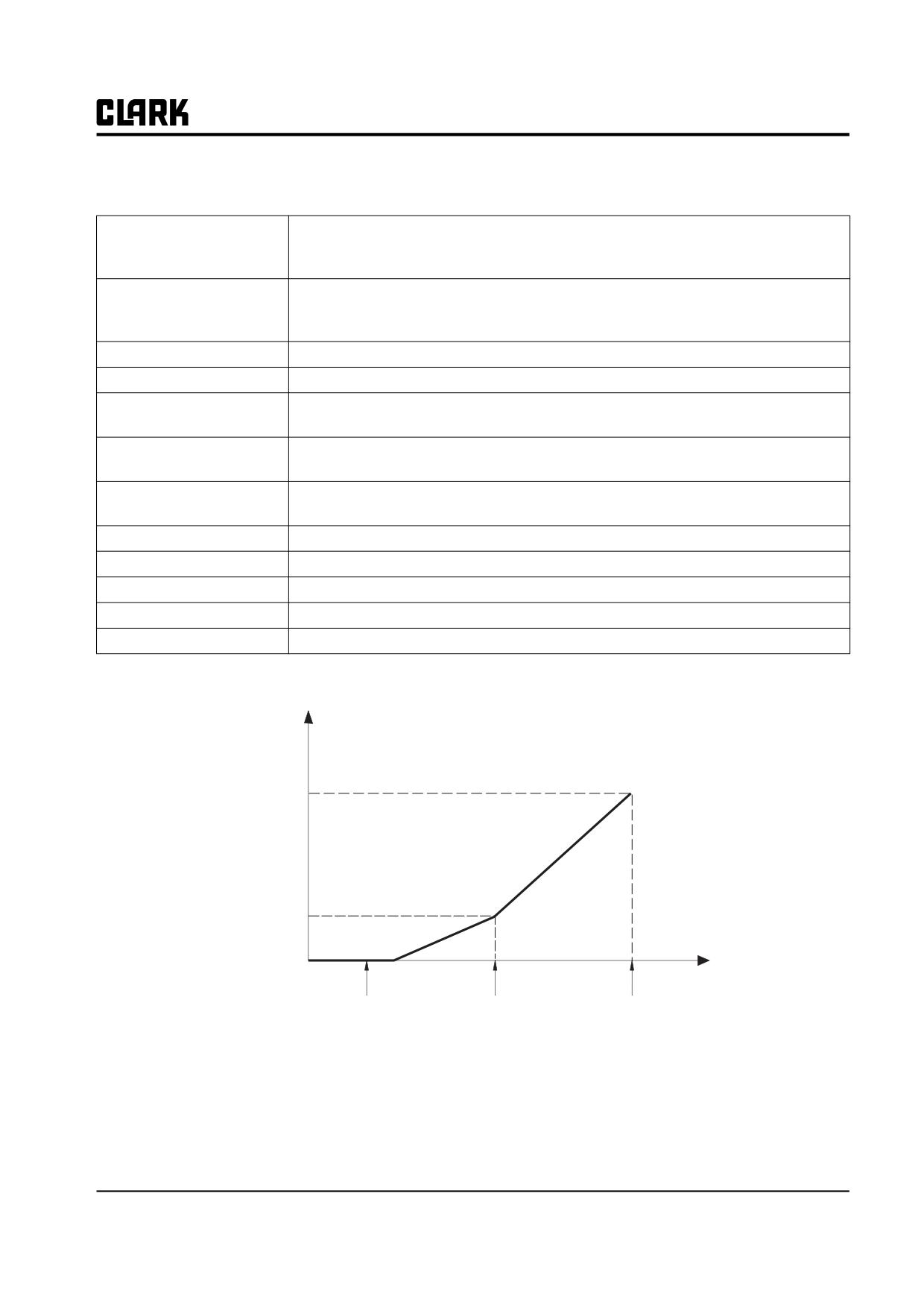
11. THROTTLE X POINT:
This parameter changes the characteristics of the accelerator input curve
12. THROTTLE Y POINT:
This parameter changes the characteristics of the accelerator input curve
SPEED f(Hz)
MAX SPEED
TROTTLE Y
POINT
FREQ. CREEP
V
TROTTLE X
VACC
VACC
TROTTLE 0
MIN
POINT
MAX
ZONE
VACC MIN and VACC MAX are values programmable by the "PROGRAM VACC" function.
This VACC procedure programs the actual minimun and maximum input voltages from the accelerator control.
See Group 13, Section 4 for setup procedure.
SM 765, Sep ’06
Control Programming • 19-2-5
Group 19, Motor Controls
13. ADJUSTMENT #04:
Determines the motor temperature level at which the "Motor Temperature" fault is
(Do Not Change)
signaled. The default temperature is 130° C. Icon on dash will illuminate at this
temperature.
14. MOTOR SHUTDOWN:
This parameter determines the motor temperature level at which the "Motor Shut-
(Do Not Change)
down" fault is signaled. The default temperature is 145° C.
15. ADJUSTMENT #01
Adjust the upper level of the battery discharge table.
16. ADJUSTMENT #02
Adjust the lower level of the battery discharge table.
17. ADJUSTMENT #3
Adjust percentage of battery change it take to reset battery state of charge on dash
display.
18. MAIN CONT VOLTAGE:
Adjusts the Line contactor coil voltage (PWM output C26).
19. AUX OUTPUT VOLTAGE:
Adjusts the Electric brake coil voltage (PWM output C28).(Not Used)
20. MAINTENANCE DONE:
OFF is the default Setting. When a maintenance warning occurs, the operator can
cancel the warning setting this parameter ON. When the truck is turned on again
this parameter becomes OFF.
21. MAINTENANCE:
-NONE:
When truck reaches maintenance time, if this parameter is set as NONE, the con-
troller gives a maintenance warning but does not reduce performance.
OPTION #1:
When truck reaches maintenance time, if this parameter is set as OPTION #1, the
controller gives a maintenance warning and reduces truck performance
OPTION # 2:
When truck reaches maintenance time, if this parameter is set as OPTION #2, the
controller gives a maintenance warning and stops the truck.
22. MAINTENANCE TIME:
Sets the number running truck hours before setting the maintenance fault. This is a
count down timer, it must be reset after each PM.
23. 1x 10, 000 HOURS:
Sets the ten thousands units of the hour meter displayed on the dash display. This
will not change the hour meter of the controller.
24. 1x 1, 000 HOURS:
Sets the thousands units of the hour meter displayed on the dash display. This will
not change the hour meter of the controller.
25. 1x 100 HOURS:
Sets the hundreds units of the hour meter displayed on the dash display. This will
not change the hour meter of the controller.
26. 1x 10 HOURS:
Sets the ten units of the hour meter displayed on the dash display. This will not
change the hour meter of the controller.
27. 1x 1 HOURS:
Sets the units of the hour meter displayed on the dash display. This will not change
the hour meter of the controller.
19-2-6 • Control Programming
SM 765, Sep ’06
Group 19, Motor Controls
Parameter Regulation
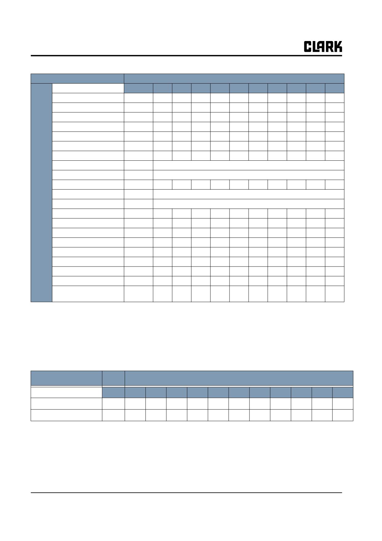
The following parameters can be modified( See Group 19, Section 4 for Clark factory recommended settings)
1. ACC DELAY:
Determines the acceleration ramp
2. RELEASE BRAKING:
Controls the deceleration ramp when the travel request (accelerator) is released
The higher the setting, the more aggressive the braking.
3. INVERSION BRAKING:
Controls the deceleration ramp when the direction is changed (FWD to REV or
REV to FWD) during travel.
The higher the setting, the more aggressive the braking.
4. PEDAL BRAKING:
Determines the deceleration ramp when the travel request is (accelerator) released
and the brake pedal switch is closed.
The higher the setting, the more aggressive the braking.
5. SPEED LIMIT BRAKING:
Deceleration ramp when the pedal position is changed but not completely released
6. BRAKE CUTBACK:
Determines the deceleration ramp when the speed reduction input becomes active
and the motor slows down.
7. CURVE BRAKING:
Determines the rate of the decelleration ramp in a curve as the steer wheel is
(Do Not Change)
turned.
8. MAX SPEED FORWARD:
Determines maximum speed in forward direction.
9. MAX SPEED BACKWARD:
Determines maximum speed in reverse direction.
10. CURVE CUTBACK:
Speed reduction when the truck in a turn. The parameter sets the speed set point
(CLARK Special)
when the truck driving wheels are running in opposite direction (3 wheel truck,
steering angle greater than roughly 67°); or when the maximum steering angle is
reached (4 wheel truck, the internal wheel is stopped). In intermediate steering
angles, the speed set point will be within a range between the straight wheel speed
and the CURVE CUTBACK SPEED.
11. CURVE CUTBACK #1:
Determines the speed of the inside wheel as the steering wheel is turned.
12. CUTBACK SPEED1:
Speed reduction when cutback switch1 is active.
(Not Used)
13. FREQUENCY CREEP:
Minimum speed when the forward or reverse switch is closed, but the accelerator
(Do Not Change)
is in a minimum position.
14. MAXIMUM CURRENT:
Changes the maximum current of the controller
(Do Not Change)
15. AUXILIARY TIME:
Determines the time that the truck will hold on a ramp if the "stop on ramp" option
(Do Not Change)
is ON.
16. SEAT MICRO DELAY:
Used to set up the Delay value to open the seat switch.
17. ACC SMOOTH
ACC SMOOTH controls the acceleration rate, when the speed request is between 0
Hz and the frequency setting defined by STOP SMOOTH. When the speed request
is above the STOP SMOOTH value, then the parameter ACCELERATION
DELAY controls the acceleration rate. Adjusting this level changes the time (in
seconds) required to accelerate the truck. The lower the acceleration level the
more aggressive the acceleration is.
18. INV SMOOTH
INV SMOOTH is similar to ACC SMOTH but it controls the acceleration rate after
the truck is plugged to a complete stop and starts to accelerate in the opposite
direction.
19. STOP SMOOTH
Sets the frequency point where ACC SMOOTH stops and ACCELERATION
DELAY starts.
20. IDLE TIME
Sets the main line Contactor open time.
SM 765, Sep ’06
Control Programming • 19-2-7
Group 19, Motor Controls
PARAMETERS
PROGRAM LEVEL
Unit
0
1
2
3
4
5
6
7
8
9
Acceleration Delay (*)
Sec.
1
1.5
1.8
2.0
2.5
3
3.5
4
4.5
5
Release Braking (**)
Sec.
25
20
18
15
10
8
6
4
3
2
Inversion Braking (**)
Sec.
5.5
5
4.5
4
3.5
3
2.5
2
1.5
1
Pedal Braking (**)
Sec.
5.5
5
4.5
4
3.5
3
2.5
2
1.5
1
Speed Limit Barking (**)
Sec.
8.9
8.3
7.7
7.1
6.6
6
5.5
4.9
4.4
3.8
Brake Cutback (**)
Sec.
5.5
5
4.5
4
3.5
3
2.5
2
1.5
1
Curve Braking
Sec.
1.5
1.4
1.3
1.2
1.1
1
0.9
0.8
0.7
0.6
Max speed Forw
Hz
0 ~ 200
Max speed Back
Hz
0 ~ 200
Dual
Cutback Speed
%
10
20
30
40
50
60
70
80
90
100
AC2
Cutback Speed 2
%
0 ~ 100
PW(8
0V)
Curve Cutback
%
0 ~ 100
Curve Cutback #1
%
55
60
65
70
75
80
85
90
95
100
Frequency Creep
Hz
0.3
0.6
0.9
1.2
1.5
1.8
2.1
2.4
2.7
3
Maximum Current
% IMAX
47
53
59
65
71
76
82
88
94
100
Auxiliary Time
Sec.
0
1.5
3.0
4.5
6.0
7.5
9.0
10.5
12
15
Seat Micro Delay
Sec.
2.0
2.1
2.3
2.4
2.6
2.8
2.9
3.1
3.3
3.5
Acc. Smooth
Sec.
1.0
1.2
1.5
1.7
2.0
2.2
2.5
2.7
3.0
3.5
Inv. Smooth
Sec.
1.0
1.2
1.5
1.7
2.0
2.2
2.5
2.7
3.0
3.5
Stop Smooth
Hz
5
7
10
12
15
17
20
22
25
27
Idle time
Min
1
2
3
4
6
8
10
12
15
20
(***)
*)The acceleration time shown is the time from 0 Hz to 100 Hz. This is the ideal ramp calculated by the software; the real
ramp could change as afunction of motor control parameter setting and, obviously, a function of the load.
(**)The braking feature is base on deceleration ramps. The value shown in the table is the time to decrease the speed from
100 Hz to 0 Hz. This is the ideal ramp calculated by the software; the real ramp could change as afunction of motor con-
trol parameter setting and, obviously, a function of the load.
(***)(Always closed).
PARAMETERS
SPEED EMPTY MPH
MPH
1
2
3
4
5
6
7
8
9
10
11.1
MAX SPEED FORWARD
HZ
13
26
38
51
63
76
88
101
114
126
140
MAX SPEED REVERSE
HZ
13
26
38
51
63
76
88
101
114
126
140
NOTE
Maximum speed for the GEX20/30 can not exceed 140 Hz.
Maximum speeds are adjustable from 0 Hz to 140 Hz in 1 Hz increments. Forward speed and reverse speeds can be set
independently (Forward speed can be set to 8 MPH and Reverse speed can be set at 5MPH if desired)
19-2-8 • Control Programming
SM 765, Sep ’06
Group 19, Motor Controls
TESTER MENU
The most important input or output signals can be measured in real time using the TESTER function of the handset. The
handset acts as a multimeter able to read voltage, current and temperature. The following is a list of measurements for
different configurations.
Handset Tester: user can verify the state of the following parameters:
MASTER CONTROL
Truck Hour Meter(HRs)
Accelerator (V)
Brake switch (ON/OFF)
Motor voltage (%)
Steer Angle (°)
Exclusive hydro (ON/OFF)
Frequency (Hz)
Int wheel cutback (%)
Brake pedal poti (%)
Encoder (Hz)
Forw switch (ON/OFF)
Hand brake (ON/OFF)
Slip Value (Hz)
Back switch (ON/OFF)
Voltage booster (%)
Current RMS (A)
Enable switch (ON/OFF)
Battery voltage (V)
Temperature (°C)
Seat switch (ON/OFF)
Battery charge (%)
Temperature #1 (°C)
Cutback switch (ON/OFF)
Temperature #2 (°C)
Cutback switch2 (ON/OFF)
Master Control - "Dualac2 Power 80V"
1) TRUCK HOUR METER:
Shows truck hour meter
2) MOTOR VOLTAGE:
This is the voltage supplied to the motor by the controller; it is expressed as a percent-
age of full battery voltage.
3) FREQUENCY:
This is the frequency of the voltage and current supplied to the motor.
4) ENCODER:
This is the speed of the motor, expressed in the same unit of the frequency; this infor-
mation comes from the speed sensor.
5) SLIP VALUE:
This is the difference of speed between the rotating field and the shaft of the motor,
expressed in the same unit of the frequency.
6) CURRENT RMS:
Root Mean Square value of the motor current.
7) TEMPERATURE:
The temperature measured on the aluminum heat sink holding the MOSFET devices.
8) TEMPERATURE #1:
This is the temperature of the right motor; if this option is programmed "None" it
shows 0°.
9) TEMPERATURE #2:
This is the temperature of the left motor; if this option is programmed "None" it shows
0°.
10) ACCELERATOR:
The voltage of the accelerator potentiometer's wiper (CPOT). The voltage level is
shown on the left-hand side of the Handset display and the value in percentage is
shown on the right-hand side.
11) STEER ANGLE:
This is the indication off the angular position of the steer wheel.
12) INTERNAL WHEEL
This is an indication of the speed reduction applied to the inside wheel; in other words,
CUTBACK:
it shows the ratio of the two speeds.
13) FORWARD SWITCH:
The level of the Forward direction digital input FW.
ON /+BV = input active, switch closed.
OFF / GND = input non-active, switch open.
14) BACKWARD SWITCH:
The level of the Reverse direction digital input BW.
ON /+BV = input active, switch closed.
OFF / GND = input non-active, switch open.
SM 765, Sep ’06
Control Programming • 19-2-9
Group 19, Motor Controls
15) ENABLE SWITCH:
The level of the Enable digital input.
ON /+BV = input active, switch closed.
OFF / GND = input non-active, switch open.
16) SEAT SWITCH:
The level of seat microswitch digital input.
ON /+BV = input active, switch closed.
OFF / GND = input non-active, switch open.
17) CUTBACK SWITCH:
The level of the Speed Reduction microswitch.
ON /+BV = input active, switch closed.
OFF / GND = input non-active, switch open.
18) CUTBACK SWITCH2:
The level of the Speed Reduction microswitch.
ON /+BV = input active, switch closed.
OFF / GND = input non-active, switch open.
19) BRAKE SWITCH:
The level of the brake microswitch.
ON /+BV = input active, switch closed.
OFF / GND = input non-active, switch open.
20) EXCLUSIVE HYDRO:
Status of the exclusive hydro switch.
ON /+BV = input active, switch closed.
OFF / GND = input non-active, switch open.
21) BRAKE PEDAL POTI:
Voltage of the brake potentiometer's wiper (CPOTB). The parameter is active only if
the "PEDAL BRAKING" parameter is set to "ANALOG".
22) HAND BRAKE:
The level of the Handbrake microswitch.
ON /+BV = input active, switch closed.
OFF / GND = input non-active, switch open
23) VOLTAGE BOOSTER:
This is the booster voltage supplied to the motor in load condition; It is expressed in a
percentage of the full voltage.
24) BATTERY VOLTAGE:
Level of the battery voltage measured at the input of the key switch.
25) BATTERY CHARGE:
The percentage charge level of the battery.
19-2-10 • Control Programming
SM 765, Sep ’06
Group 19, Motor Controls
Slave Control - "Dualac2 Power (80V)"
Submenu "Adjustments"
1. SET BATTERY TYPE: Selects nominal battery voltage
2. ADJUST BATTERY: Fine adjustment of the battery voltage measured by the controller.
GEX Handset
Slave Control Configuration
DISPLAY
DM2S2BGCPE CK 0.13
DM2S2BGCPE CK 0.13
80V 280A 00000
DISPLAY
80V 280A 00000
KEYBOARD
KEYBOARD
HEADING
Enter
Main Menu
Set Model
Connected to 4 (Slave) (3 = Master, 5 = Pump)
Roll
Parameter
Enter
Not Available
Up
Change
Enter
Set Options
Not Available
Roll
Roll
Up
Up
Enter
Enter
Adjustments
Set Battery Type
48/72/80/96
Tester
Motor Voltage
%
Adjust Battery
Frequency
Hz
Aux Output Voltage
Encoder
Hz
Slip Value
Hz
Current RMS
A
Roll
Temperature
Up
Seat Switch
On/Off
Forward Switch
V
Reverse Switch
V
Enable Switch
On/Off
Voltage Booster
%
Battery Voltage
V
Save
Parameter
Roll
Up
Restore
Parameter
Roll
Up
Enter
Alarms
Roll
Up
Program
Enter
VACC Settings
Min/Max
VACC
Roll
Up
Enter
Motor Data
Not Available
See Group 19, Section 4 for GEX Factory Control Settings
SM 765, Sep ’06
Control Programming • 19-2-11
Group 19, Motor Controls
TESTER MENU
The most important input or output signals can be measured in real time using the TESTER function of the handset. The
handset acts as a multimeter able to read voltage, current and temperature. The following is a list of measurements for
different configurations.
Handset Tester: user can verify the state of the following parameters:
SLAVE CONTROL
Motor voltage (%)
Current RMS (A)
Back switch (ON/OFF)
Frequency (Hz)
Temperature (°C)
Enable switch (ON/OFF)
Encoder (Hz)
Seat switch (ON/OFF)
Voltage booster (%)
Slip Value (Hz)
Forw switch (ON/OFF)
Battery voltage (V)
Slave Control - "Dualac2 Power 80V"
1) MOTOR VOLTAGE:
This is the voltage supplied to the motor by the controller; it is expressed as a percentage
of full battery voltage.
2) FREQUENCY:
This is the frequency of the voltage and current supplied to the motor.
3) ENCODER:
This is the speed of the motor, expressed in the same unit of the frequency; this informa-
tion comes from the speed sensor.
4) SLIP VALUE:
This is the difference of speed between the rotating field and the shaft of the motor,
expressed in the same unit of the frequency.
5) CURRENT RMS:
Root Mean Square value of the motor current.
6) TEMPERATURE:
The temperature measured on the aluminum heat sink holding the MOSFET devices.
7) SEAT SWITCH:
The level of seat microswitch digital input.
ON /+BV = input active, switch closed.
OFF / GND = input non-active, switch open.
8) FORWARD SWITCH:
The level of the Forward direction digital input FW.
ON /+BV = input active, switch closed.
OFF / GND = input non-active, switch open.
9) BACKWARD SWITCH:
The level of the Reverse direction digital input BW.
ON /+BV = input active, switch closed.
OFF / GND = input non-active, switch open.
10) ENABLE SWITCH:
The level of the Enable digital input.
ON /+BV = input active, switch closed.
OFF / GND = input non-active, switch open.
11) VOLTAGE BOOSTER:
This is the booster voltage supplied to the motor in load condition; It is expressed in a per-
centage of the full voltage.
12) BATTERY VOLTAGE:
Level of the battery voltage measured at the input of the key switch.
19-2-12 • Control Programming
SM 765, Sep ’06
Group 19, Motor Controls
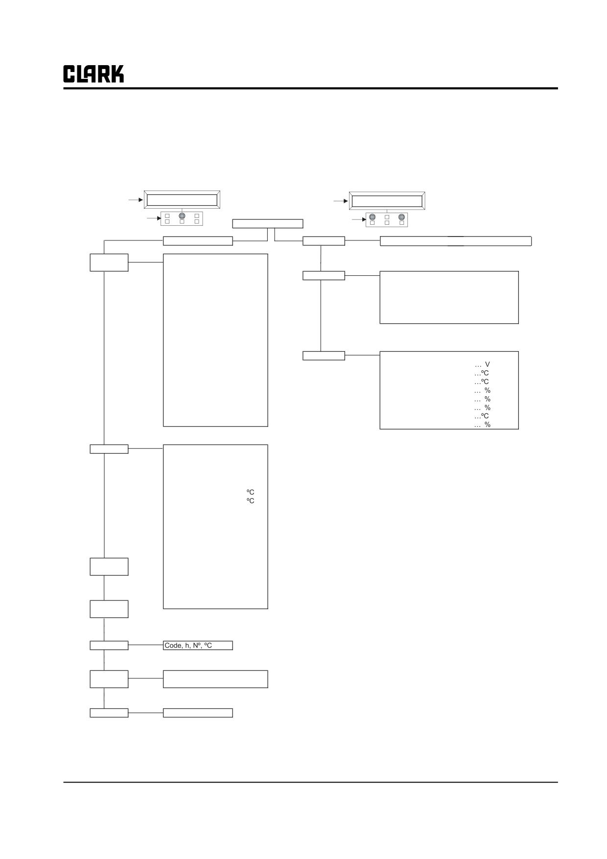
PUMP CONTROL
Using the configuration menu of the programming console, the user can configure the following functions.
GEX Handset
Pump Control Configuration
AC3P2BIG CK0.09
AC3P2BIG CK0.09
DISPLAY
80V 450A 00000
DISPLAY
80V 450A 00000
KEYBOARD
KEYBOARD
HEADING
Enter
Main Menu
Set Model
Connected to 5 (Pump) (3 = Master, 4 = Slave)
Roll
Parameter
Enter
Acceleration Delay
0-9
Up
Change
Decelleration Delay
0-9
Enter
Acc delay Tilt
0-9
Set Options
Hour Meter
Running / Key On
Dec delay Tilt
0-9
Set Temperature
Analog / Digital / None
Aux1 Acc delay
0-9
Roll
Therm Protection
On/Off
Roll
Aux1 Dec delay
0-9
Up
Hour Meter Truck
On/Off
Up
Aux2 Acc delay
0-9
Pressure Funct
On/Off
Aux2 Dec delay
0-9
Digital lift
On/Off
Max Speed Up
Hz
Min Speed Up
Hz
Cutback speed
%
1st Speed
Hz
Enter
Adjustments
Set Battery Type
48/72/80/96
2nd Speed
Hz
Adjust Battery
3rd Speed
Hz
Adjustment #04
4th Speed
Hz
Adjustment #03
Hydro Speed
Hz
Throttle 0 Zone
Idle Speed
Hz
Throttle Y Zone
Idle Time
Sec
Throttle X Zone
Maximum Current
0-9
Motor Shutdown
Auxilary Time
Sec
IMAX Protection
Enter
Tester
Motor Voltage
%
Frequency
Hz
Encoder
Hz
Slip Value
Hz
Current RMS
A
Temperature
Roll
Motor Temperature
Up
Accelerator
V
Lift Switch
On/Off
1st Speed Switch
On/Off
2nd Speed Switch
On/Off
3rd Speed Switch
On/Off
4th Speed Switch
On/Off
Save
Hydro Speed Req
On/Off
Parameter
Voltage Booster
V
Battery Voltage
V
Roll
COS FI
Up
Battery Current
A
Restore
Battery Charge
%
Parameter
Roll
Up
Enter
Alarms
Roll
Up
Program
Enter
VACC
VACC Settings
Min/Max
Roll
Up
Enter
Motor Data
Not Available
SM 765, Sep ’06
Control Programming • 19-2-13
Group 19, Motor Controls
SUBMENU "SET OPTIONS"
1 HOUR METER TRUCK
RUNNING:
The meter registers when the "key" is ON
KEY ON:
The meter registers travel time only.
2 SET TEMPERATURE
DIGITAL:
A digital (ON/OFF) motor thermal sensor is connected to F6 input.
ANALOG:
An analog motor thermal sensor is connected to F6(the curve can be customized on customer
request).
None:
No motor sensor switch connected.
3 THERMO PROTECTION
ON:
When motor winding temperature is over 90°…, reduce the torque
OFF:
Always pull torque should be provided.
4 HOUR METER TRUCK
ON:
Equipment usage time should be shared between travel and hydraulic controller.
OFF:
Equipment usage time should not be shared.
5 PRESSURE FUNCT
ON:
Use pressure sensor to operate steering motor.
OFF:
Operate steering motor by ahead/astern lever without pressure sensor.
6 DIGITAL LIFT
ON:
Operate lift without potentiometer(operated by ON/OFF switch)
OFF:
Lift speed is relative to the output value of potentiometer.
19-2-14 • Control Programming
SM 765, Sep ’06
Group 19, Motor Controls
SUBMENU "ADJUSTMENTS"
1. SET BATTERY TYPE:
Selects nominal battery voltage.
2. ADJUST BATTERY:
Fine adjustment of battery voltage measured by the controller.
3. ADJUSTMENT #4:
Used to decide the motor temp level on which the motor temp abnormal signal is dis-
played. The temp range will be adjusted from 70°C to 160°C in the unit of 10°C. This
parameter shall be adjusted only when the “Temp Adjustment” (“Option” menu) parame-
ter has been programmed in analog.
4.
MOTOR
SHUT-
Used to shut down the hydraulic operation when the set value is reached. (However, the
DOWN:
steering can work.)
5. THROTTLE 0 ZONE:
Establishes a deadband in the accelerator input curve.
6. THROTTLE X POINT:
This parameter changes the characteristics of the accelerator input curve.
7. THROTTLE Y POINT:
This parameter changes the characteristics of the accelerator input curve.
8. IMAX PROTECTION:
The value to start the current reduction when the motor temperature reaches adjustment
#4 value.
SPEED f(Hz)
MAX SPEED
TROTTLE Y
POINT
FREQ. CREEP
V
TROTTLE X
VACC
VACC
TROTTLE 0
MIN
POINT
MAX
ZONE
VACC MIN and VACC MAX are values programmable by the "Program VACC" function.
This VACC procedure programs the actual minimun and maximum input voltages from the lift potentiometer.
See Group 13, Section 4 for setup procedure.
SM 765, Sep ’06
Control Programming • 19-2-15
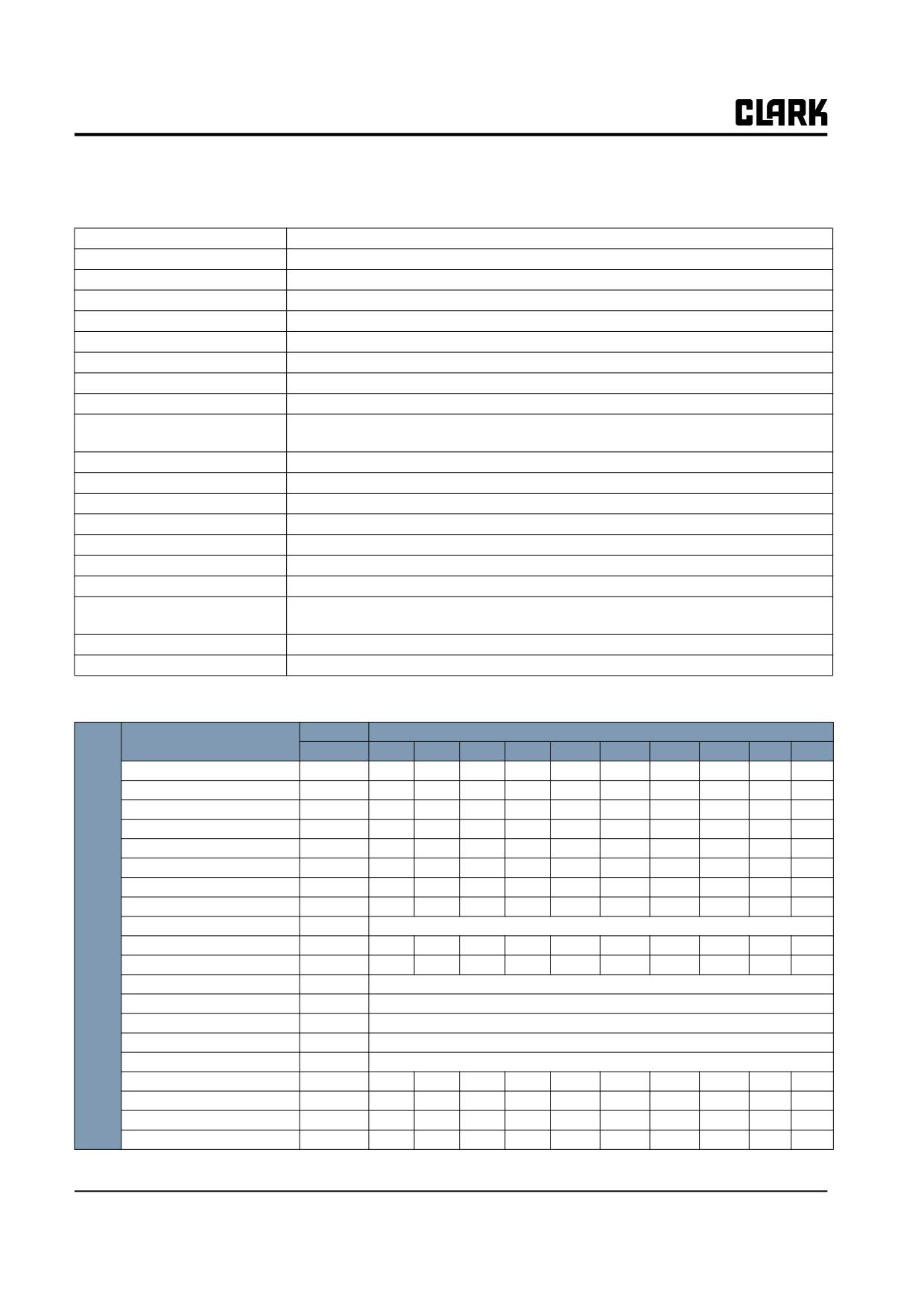
Group 19, Motor Controls
Parameter Regulation: Pump Configuration
The following parameters can be modified:
1. Acceleration Delay
Acceleration ramp for lift(See Tables Below).
2. Deceleration Delay
Deceleration ramp for lift(See Tables Below).
3. Acceleration Delay Tilt
Acceleration ramp for tilt(See Tables Below).
4. Deceleration Delay Tilt
Deceleration ramp for tilt(See Tables Below).
5. Acceleration Delay Aux1
Acceleration ramp for Aux1(See Tables Below).
6. Deceleration Delay Aux1
Deceleration ramp for Aux1(See Tables Below).
7. Acceleration Delay Aux2
Acceleration ramp for Aux2(See Tables Below).
8. Deceleration Delay Aux2
Deceleration ramp for Aux2(See Tables Below).
9. Max Speed Up:
Determine the maximum lifting speed with a Potentiometer control (See Tables Below).
10. Min Speed Up:
Determine the minimum lifting speed with a potentiometer control when the lifting
enable switch is closed (See Tables Below).
11. Cutback Speed
Speed when cutback switch is activated
12. 1st Speed Fine:
First speed (Tilt Speed), fine adjustment (See Tables Below).
13. 2nd Speed Fine:
Second speed, fine adjustment (See Tables Below).
14. 3rd Speed Fine:
Third speed, fine adjustment (See Tables Below).
15. 4th Speed Fine:
Fourth speed, fine adjustment.
16. Hyd Speed Fine:
Hydro speed, fine adjustment.
17. Idle Speed:
Set speed when steer on demand is active but pressure sensor is not moving. (Not used)
18. Idle Time:
The set time delay before stopping the motor when steer demand is active and pressure
sensor is not moving. (Not used)
19. Max Current:
Maximum current of the controller (See Tables Below).
20. Auxilary Time:
Time delay when power steering function request is switched off (See Tables Below).
The following tables show the different value at which the parameters can be set.
PROGRAM LEVEL
PARAMETERS
UNIT
0
1
2
3
4
5
6
7
8
9
Acceleration Delay
Sec.
0.5
0.7
1
1.4
1.9
2.5
3.2
4
4.8
5.5
Deceleration Delay
Sec.
0.5
0.7
1
1.4
1.9
2.5
3.2
4
4.8
5.5
Acceleration Delay Tilt
Sec.
0.5
0.7
1
1.4
1.9
2.5
3.2
4
4.8
5.5
Deceleration Delay Tilt
Sec.
0.5
0.7
1
1.4
1.9
2.5
3.2
4
4.8
5.5
Acceleration Delay Aux1
Sec.
0.5
0.7
1
1.4
1.9
2.5
3.2
4
4.8
5.5
Deceleration Delay Aux1
Sec.
0.5
0.7
1
1.4
1.9
2.5
3.2
4
4.8
5.5
Acceleration Delay Aux2
Sec.
0.5
0.7
1
1.4
1.9
2.5
3.2
4
4.8
5.5
Deceleration Delay Aux2
Sec.
0.5
0.7
1
1.4
1.9
2.5
3.2
4
4.8
5.5
AC3
Max Speed Up
Hz
0-200
PW
Min Speed Up
Hz
0
13.5
15
16.5
18
19.5
21
22.5
24
25.5
(80V)
Cutback Speed
%
10
20
30
40
50
60
70
80
90
100
1st Speed Fine
Hz
0-200
2nd Speed Fine
Hz
0-200
3rd Speed Fine
Hz
0-200
4th Speed Fine
Hz
0-200
Hyd Speed Fine
Hz
0-200
Idle Speed
Hz
6
8
10
12
14
16
18
20
22
24
Idle Time
Sec.
1
2
4
8
10
12
14
16
18
20
Max Current
% IMAX
44
50
56
63
69
75
81
87
94
100
Auxilary Time
Sec.
0
1
2
3
4
6
8
10
12
15
19-2-16 • Control Programming
SM 765, Sep ’06
Group 19, Motor Controls
TESTER MENU
The most important input or output signals can be measured in real time using the TESTER function of the handset. The
handset acts as a multimeter able to read voltage, current and temperature. The following is a list of measurements for
different configurations.
Handset Tester: user can verify the state of the following parameters:
PUMP CONTROL
Motor voltage (%)
Accelerator (V)
Hydro speed req. (ON/OFF)
Frequency (Hz)
Lifting switch (ON/OFF)
Voltage booster (%)
Encoder (Hz)
1st speed switch (ON/OFF)
Battery voltage (V)
Slip Value (Hz)
2nd speed switch (ON/OFF)
Cos fi
Current RMS (A)
3rd speed switch (ON/OFF)
Battery Current (A)
Temperature (°C)
4th speed switch (ON/OFF)
Battery charge (%)
Motor Temperature (°C)
1) MOTOR VOLTAGE:
This is the voltage supplied to the motor by the controller; it is expressed as a percent-
age of full battery voltage.
2) FREQUENCY:
This is the frequency of the voltage and current supplied to the motor.
3) ENCODER:
This is the speed of the motor, expressed in the same unit of the frequency; this infor-
mation comes from the speed sensor.
4) SLIP VALUE:
This is the difference of speed between the rotating field and the shaft of the motor,
expressed in the same unit of the frequency.
5) CURRENT RMS:
Root Mean Square value of the motor current.
6) TEMPERATURE:
The temperature measured on the aluminum heat sink holding the MOSFET devices.
7) MOTOR TEMPERATURE:
This is the temperature of the right motor; if this option is programmed "None" it
shows 0°.
8) ACCELERATOR:
The voltage of the accelerator potentiometer's wiper (CPOT). The voltage level is
shown on the left-hand side of the console display and the value is in percentage is
shown on the right-hand side
9) LIFTING SWITCH:
Status of lifting switch.
ON /+BV = input active, switch closed.
OFF / GND = input non-active, switch open.
10) TILT SPEED SWITCH:
ON /+BV = input active, switch closed.
OFF / GND = input non-active, switch open.
11) AUX1 SPEED SWITCH:
ON /+BV = input active, switch closed.
OFF / GND = input non-active, switch open.
SM 765, Sep ’06
Control Programming • 19-2-17
Group 19, Motor Controls
12) AUX2 SPEED SWITCH:
ON /+BV = input active, switch closed.
OFF / GND = input non-active, switch open.
13) AUX3 SPEED SWITCH:
ON /+BV = input active, switch closed.
OFF / GND = input non-active, switch open.
14) HRYDRO SPEED REQ.:
ON /+BV = input active, switch closed.
OFF / GND = input non-active, switch open.
15) VOLTAGE BOOSTER:
This is the booster voltage supplied to the motor in load condition; It is expressed in a
percentage of the full voltage.
16) BATTERY VOLTAGE:
Level of the battery voltage measured at the input of the key switch.
17) COS FI:
This is cosj (real time calculated) of the motor.
18) BATTERY CURRENT:
This is the battery current (not measured but calculated.
19) BATTERY CHARGE:
The percentage charge level of the battery
OTHER HANDSET FUNCTIONS
Save and Restore Function
SAVE Function allows the transfer of controller parameters to the PC memory. With this function, a copy of the control-
ler's set of parameters can be retained in a Pc and downloaded to another controller (see restore).
RESTORE Function allows you to download controller parameters from the PC memory to the controller Eeprom. Thus
a copy of the parameters stored in the Pc can be downloaded in a controller avoiding the parameter setting operation.
SETUP for INSTALLING A NEW CONTROL PANEL
Sequence for AC Traction Controller Setting
When the "Key Switch" is turned ON, if no faults are present, the Zapi Handset Display will be showing the standard
Opening Display.
If the controller is not configured to your requirements, follow the sequence detailed below. Remember to cycle the key
switch if you make any changes to the controller configuration.
1) Select the options required.
2) Select and set battery voltage.
3) Confirm correct installation of all wires. Use Handset's TESTER function to assist.
4) Perform the accelerator signal acquisition procedure using the Handset "PROGRAM VACC".(See Group 13, Sec-
tion 4 for programming procedures).
5) Perform the steering potentiometer signal acquisition, using the parameters in "Adjustment" menu.(See Group 13,
Section 4 for programming procedures).
Remember: when turning the wheel to the right the voltage will increase.
19-2-18 • Control Programming
SM 765, Sep ’06
Group 19, Motor Controls
6) Set the maximum steering angles, right and left; use the parameters in "Adjustment" menu. (See Group 13, Sec-
tion 4 for programming procedures).
7) Verify “BATTERY VOLTAGE”. Use volt meter to determine voltage between +BT and -B on the controller.
8) Verify the "MAXIMUM CURRENT"
9) Verify the acceleration delay requirements for the truck. Test the parameter setting in both directions.
10) Verify the FREQENCY CREEP level starting from level 0.3 Hz. The truck should just move when the accelera-
tor start switch is closed. Increase the level accordingly.
11) Verify speed reduction.
12) Set Hour Meter to correct hours.
SM 765, Sep ’06
Control Programming • 19-2-19
NOTE :
Group 19, Motor Controls
SM 765, Sep ’06
Group 19, Motor Controls
Section 3
CONTROL TROUBLESHOOTING
FAULT CODES FOR GEX
This is the list of codes that the CLARK dash display may show
Fault
Fault Name
Control
Fault
Fault Name
Control
Code
Code
140
" HIGH TEMPERATURE"
SLAVE
1
"NO SEAT SWITCH"
MASTER
148
"ENCODER ERROR"
SLAVE
2
"CHOPPER RUNNING"
MASTER
150
"WATCHDOG"
PUMP
8
"WATCHDOG"
MASTER
151
"CHOPPER RUNNING"
PUMP
9
"INPUT MISMATCH"
MASTER
155
"EEPROM KO"
PUMP
10
"WAITING DISPLAY"
MASTER
159
"LOGIC FAILURE #3
PUMP
13
"EEPROM KO"
MASTER
160
"LOGIC FAILURE #2
PUMP
17
"LOGIC FAILURE #3
MASTER
161
"LOGIC FAILURE #1
PUMP
18
"LOGIC FAILURE #2
MASTER
171
"MOTOR SHUTDOWN"
PUMP
19
"LOGIC FAILURE #1
MASTER
172
"VMN LOW"
PUMP
30
"VMN LOW"
MASTER
173
"VMN HIGH"
PUMP
31
"VMN HIGH"
MASTER
174
"TH MOTOR SENSOR KO"
PUMP
33
"IDLE TIME"
MASTER
182
"MOTOR LOCKED"
PUMP
37
"CONTACTOR CLOSED"
MASTER
195
"STBY I HIGH"
PUMP
38
"CONTACTOR OPEN"
MASTER
196
"THERMIC SENSOR KO"
PUMP
53
"STBY I HIGH"
MASTER
201
"ENCODER ERROR"
PUMP
60
"CAPACITOR CHARGE"
MASTER
202
"CAP CHARGE"
PUMP
61
" HIGH TEMPERATURE"
MASTER
203
" HIGH TEMPERATURE"
PUMP
65
"MOTOR TC START"
MASTER
204
"VACC NOT OK"
PUMP
66
"BATTERY LOW"
MASTER
205
"INCORRECT START"
PUMP
71
"MOTOR SHUTDOWN"
MASTER
206
"PEDAL WIRE KO"
PUMP
72
"MOTOR LOCKED"
MASTER
207
"MOTOR TC START"
PUMP
74
"DRIVER SHORTED"
MASTER
208
"BATTERY LOW "
PUMP
75
"CONTACTOR DRIVER"
MASTER
211
"COIL SHORTED"
PUMP
76
"COIL SHORTED"
MASTER
212
"COIL INTERUPTED"
PUMP
77
"MAINTENANCE HOURS"
MASTER
217
"WRONG SET BATTERY"
PUMP
78
"VACC NOT OK"
MASTER
218
"SAFETY"
PUMP
79
"INCORRECT START (SRO)"
MASTER
222
"NO CAN MSG"
PUMP
80
"FORWARD + REVERSE"
MASTER
225
"AUX OUTPUT KO"
PUMP
81
"TH MOTOR SENSOR KO"
MASTER
232
"MASTER KO"
SLAVE
82
"ENCODER ERROR"
MASTER
233
"NO CAN MSG 3"
SLAVE
84
"STEER SENSOR KO"
MASTER
235
"THERMIC SENSOR KO"
SLAVE
86
"PEDAL WIRE KO"
SLAVE
236
"INPUT MISMATCH"
SLAVE
87
"WATCHDOG"
SLAVE
243
"NO CAN MSG 5"
MASTER
88
"WATCHDOG"
SLAVE
245
"WRONG SET BATTERY"
MASTER
96
"LOGIC FAILURE #3
SLAVE
246
"SLAVE KO"
MASTER
97
"LOGIC FAILURE #2
SLAVE
247
"NO CAN MSG 4"
MASTER
98
"LOGIC FAILURE #1
SLAVE
248
"CHECKUP NEEDED"
MASTER
99
"TH MOTOR SENSOR KO"
SLAVE
249
"THERMIC SENSOR KO"
MASTER
109
"VMN LOW"
SLAVE
253
"AUX OUTPUT KO"
MASTER
110
"VMN HIGH"
SLAVE
255
"HANDBRAKE"
MASTER
132
"STBY I HIGH"
SLAVE
Blank
"DASH DISPLAY"
MASTER
139
"CAPACITOR CHARGE"
SLAVE
SM 765, Dec ’06
CONTROL TROUBLESHOOTING • 19-3-1
Group 19, Motor Controls
Fault Code Charts
Fault
Action
Fault Name
Fault Description
Control
Troubleshooting
Code
Required
1
"NO SEAT
No input from seat
MASTER
• Controller detects the seat switch is open
SWITCH"
switch
or SLAVE
during operation.
• Check seat switch wiring and connec-
tions
Repair seat
• Check for inoperative seat switch.
switch wiring
Replace seat
switch
2
“CHOPPER
FET is running
MASTER
• XXXX
RUNNING”
8
"WATCH-
Watchdog circuit
MASTER
•
It is a self-diagnosing test within the
DOG"
has been triggered
logic between Master and Slave micro
controllers.
• This fault could also be caused by a
CAN-BUS malfunction, which blinds
Master -Slave communication. So
,
before replacing the controller , check
the Canbus
9
"INPUT
Seat Switch mis-
MASTER
• The seat switch input for traveling is dif-
MIS-
matched
ferent from that of hydraulic system.
MATCH"
• Check the seat switch line connected to
travelling controller and hydraulic con-
troller.
10
"WATCH-
Watchdog circuit
MASTER
It is a self-diagnosing test within the logic
DOG"
has been triggered
between Master and Slave micro controllers.
• This fault could also be caused by a
CAN-BUS malfunction, which blinds
Master -Slave communication. So
,
before replacing the controller , check
the Canbus
13
"EEPROM
Warning: EEprom
MASTER
• Fault in the area of memory in which the
KO"
fault controller
adjustment parameters are stored;
will use default
• This fault does not inhibit truck opera-
parameters
tion, but the controller will use default
parameters.
Replace con-
•
If fault persists when key is switched
troller
OFF and ON again.
•
If the fault disappears, remember that
the parameters stored previously have
been cancelled and replaced by the
default values.
17
"LOGIC
Failure in overload
MASTER
• Fault in the hardware section of the logic
Replace con-
FAILURE #3
protection hard-
board that manages the hardware current
troller
ware circuit
protection.
19-3-2 • CONTROL TROUBLESHOOTING
SM 765, Dec ’06
Group 19, Motor Controls
Fault
Action
Fault Name
Fault Description
Control
Troubleshooting
Code
Required
18
"LOGIC
Failure in U,V,W
MASTER
•
Fault in the hardware section of the logic
Replace con-
FAILURE #2
voltage feedback
board that manages the phase 's voltage
troller
circuit
feedback.
19
"LOGIC
An over voltage or
MASTER
•
This fault signals that the under voltage /
FAILURE #1
under voltage con-
over voltage protection interrupt has
dition has been
been triggered
detected
•
A real under voltage / over voltage key
input (C3) happened. Voltage has been
below 30V
•
A real over voltage on the power capaci-
tors happened, voltage has been 115V.
•
Fault in the hardware section of the logic
Replace con-
board that manages the over voltage pro-
troller
tection.
•
Possible plugging in or unplugging of
battery or charger with the key switch on.
30
"VMN
Wrong voltage on
MASTER
•
This test is carried out during initial diag-
Replace con-
LOW"
motor power out-
nosis and in standby. Possible causes
troller
puts; failure in the
•
problem with motor connections or the
power section or
motor power circuit; check if the
3
in the mosfet
phases are correctly connected; check if
driver circuit or in
there's chassis ground of the motor to
the motor
truck frame.
•
A problem with motor connection or
power circuit.
- Check if all 3 phases are correctly
connected.
- Check for short between motor ter-
minal and chassis
- Perform diode test
- unhook battery at controller and do
a diode check between Batt + and
Batt - (should read .3 to .5 volts)
•
Diode test
-Disconnect all power and motor leads
from control.
-Select diode test on your multi meter.
-Place positive meter lead on control -
Battery terminal place negative meter
lead on terminals U,V,W meter should
read .3V to .5V if not replace control.
-Place negative meter lead on control +
Battery terminal place positive meter
lead on terminals U,V,W meter should
read .3V to .5V if not replace control.
-If code presist replace control
• Fault in the inverter power section.
SM 765, Dec ’06
CONTROL TROUBLESHOOTING • 19-3-3
Group 19, Motor Controls
Fault
Action
Fault Name
Fault Description
Control
Troubleshooting
Code
Required
31
"VMN
Wrong voltage on
MASTER
•
This test is carried out during initial diag-
HIGH"
motor power out-
nosis and in standby. Possible causes:
puts; failure in the
•
Problem with motor connections or the
power section or
motor power circuit; check if the
3
in the mosfet
phases are correctly connected; check if
driver circuit or in
there's chassis ground of the motor to
the motor
truck frame.
•
Unhook battery at controller and do a
diode check between Batt + and Batt -
(should read .3 to .5 volts)
Replace con-
•
Fault in the controller power section.
troller
•
Possible bad battery, Excessive voltage
to case of battery.
33
"IDLE
Displayed when
MASTER
•
The main line contactor open function
TIME"
the Idle time con-
starts.
dition starts
•
Any traction inputs (Accelerator, pedal
brake, direction S/W-ON) need to close
the contactor.
37
"CONTAC-
Line contactor
MASTER
•
Before driving the line contactor coil, the
TOR
power contact
controller checks if the line contactor is
CLOSED"
closed at power up
stuck. The controller drives the bridge
for a while, trying to discharge the capac-
itor bank. If they don't dis charge, the
fault condition is entered. It is suggested
to check the contactor contact, see if it is
mechanically stuck.
38
"CONTAC-
Line contactor
MASTER
•
The controller has driven the line contac-
TOR OPEN"
power contact
tor, but the contactor did not close.
does not pull in
•
The wires to the coil are open or a loose
connection.
•
The contact does not pull in properly
53
"STBY
I
Wrong voltage in
MASTER
•
The microprocessors verify if the feed-
HIGH"
current sensor
back of current sensor device output is
feedback circuit
within the zero current window. Possible
causes of the fault.
•
Current sensor failure.
•
Failure in the controller : if the fault per-
sists, replace the power unit.
19-3-4 • CONTROL TROUBLESHOOTING
SM 765, Dec ’06
Group 19, Motor Controls
Fault
Action
Fault Name
Fault Description
Control
Troubleshooting
Code
Required
60
"CAPACI-
Power Capacitor
• When key is switched on, the controller
TOR
Voltage does not
tries to charge the capacitors through a
CHARGE"
increase when the
power resistor, and check if the capacitor
key is turned ON;
is charged (1/2 battery volts) within a
failure in power
timeout. If they do not charge, an fault is
section, or in
signaled; the line contactor does not
Logic PCB, or in
close.
driver PCB, or in
• The charging resistor is open
the motor MAS-
• The charging circuit has a failure
TER
• There is a problem in the power section.
• Possible Motor connection open.
61
"
HIGH
Warning: Master
MASTER
• Temperature of control is greater than
TEMPERA-
or Slave or both
75°C. Maximum current reduced propor-
TURE"
temperature higher
tionally to the temperature increase. At
that 75 degrees C
100°C the maximum current of both con-
trols is reduced to zero.
65
"MOTOR
Warning: Right or
MASTER
• Right or left or both drive motors analog
TC START"
left or both
or SLAVE
temperature sensor is greater than the
motors tempera-
temperature set in ADJUSTMENT #4
ture high (over
(130°C) in the ADJUSTMET submenu.
Adj #4)
Check tempera-
• When this fault occurs. Maximum cur-
ture shown on
rent is reduced to half and maximum
handset in tester
speed is reduced to 60Hz.
mode
• If it happens when the motor is cold,
Replace con-
check the wring. If all is ok,
troller
66
"BATTERY
Warning: Battery
MASTER
• When battery level reaches 20% or less
LOW"
charge level below
or (10% on the dash display), the current
20%
level for the drive motors is reduced to
50% of the programmed level and the lift
function is locked out.
71
"MOTOR
Warning: Right or
MASTER
This fault occurs when the right or left or both
SHUT-
left or both motors
motor temperature switches are open (digital
DOWN"
temp. are very
sensor), or if the analog sensor temperature
high (over
overtakes the cut off level.
MOTOR SHUT-
The cut off level is adjusted with the MOTOR
DOWN param.)
SHUTDOWN parameter
(145°C) in the
ADJUSTMENT submenu.
If this fault occurs, maximum current is
reduced to zero and the motor is stopped.
If the shutdown occurs when the motor is cold
Replace con-
check the wiring. If wiring is ok
troller
72
"MOTOR
Drive motor
MASTER
• After 15 seconds the motor stalled with
LOCKED"
locked up
maximum current, controller reduces
maximum current to 50%.
• Check if Line Contactor is pulled in.
SM 765, Dec ’06
CONTROL TROUBLESHOOTING • 19-3-5
Group 19, Motor Controls
Fault
Action
Fault Name
Fault Description
Control
Troubleshooting
Code
Required
74
"DRIVER
Line contactor coil
MASTER
•
When the key is turned ON, the micro-
SHORTED"
driver is shorted
processor checks that the line contactor
coil driver is not shorted
•
If it is, this fault is signaled.
•
Check if there is an external short or low
impedance pull-down between NLC
(C26) and -Batt.
Replace con-
•
If no external causes can be found.
troller
75
"CONTAC-
Line contactor coil
MASTER
•
When the initial diagnosis is finished, the
TOR
driver is open (not
traction logic closes the line contactor
DRIVER"
able to drive the
and checks the voltage drain of the
coil to the correct
driver.
voltage)
•
If this is not low, the driver is unable to Replace con-
close and the fault is signaled.
troller
76
"COIL
Init: Line contac-
•
When the key is turned on, the micropro-
SHORTED"
tor coil driver pro-
cessor checks that the line contactor coil
tection circuit is
driver short circuit protection hardware If
damaged or Stby
it does not react in a correct way to the
or running: short
microprocessor stimulus, the fault is sig-
on line contactor
naled.
MASTER
Replace contac-
•
When the fault occurs while the line con-
tor coil
tactor is closed this, indicates a short cir-
cuit across the line contactor coil. check
if there is an external short circuit and if
the ohmic value (xxx Omhs) of the line
contactor coil is correct
77
"MAINTE-
Displayed when
MASTER
•
This is just an indication that the vehicle
NANCE
the normal hour
is due for its Periodic Maintenance.
HOURS"
meter exceeds the
maintenance
hours set for the
vehicle
19-3-6 • CONTROL TROUBLESHOOTING
SM 765, Dec ’06
Group 19, Motor Controls
Fault
Action
Fault Name
Fault Description
Control
Troubleshooting
Code
Required
78
"VACC NOT
Warning: Accel-
MASTER
•
This fault indicates that the accelerator
OK"
erator signal
voltage is 1volt greater than the mini-
(CPOT) voltage
mum value programmed by PROGRAM
higher than
VACC function.
VACC MIN+1V
•
The potentiometer is not correctly cali-
While the trac-
brated.
tion enable
Replace accel-
•
The potentiometer is defective.
switch is open
erator
•
Use tester mode to check for voltage
change when accelerator is depressed,
should be approx 1.5volts (0.4~1.9volts
accelerator),
2.7volts
(0.4~3.1volts
accelerator) of change. If not 1.5volts
(0.4~1.9volts accelerator),
2.7volts
(0.4~3.1volts accelerator) check for wir-
ing shorts, if no shorts, replace accelera-
tor. If accelerator still doesn’t change
and voltage is greater than 2.0volts
(0.4~1.9volts accelerator) & 3.2volts
(0.4~3.1volts accelerator) replace con-
trol.
79
"INCOR-
Warning: Wrong
MASTER
•
If SRO FUNCTION is active, every time
Replace con-
RECT
traction request
work is stopped the operator must put the
troller
START
sequence This
truck in neutral.
(SRO)"
fault indicates an
•
If forward, reverse or seat switch is
incorrect start-
active when key switch is turned on.
ing sequence
•
If forward, reverse closed without seat
switch input.
•
If the fault persist after checking the wir-
ing,
80
"FOR-
Warning: For-
MASTER
•
Processor is continuously checking for a
Replace con-
WARD
+
ward and reverse
request for forward and reverse at the
troller
REVERSE"
inputs are both
same time.
active
•
Defective wiring.
•
Running micro switch failure.
•
Incorrect operation.
•
If defect persist
81
"TH
Warning:Motor
MASTER
•
The range of the motor temperature ana-
MOTOR
Master tempera-
log sensor is always checked and a fault
SENSOR
ture sensor is out
is signaled if it's out of range
KO"
of range
•
When this fault occurs. The maximum
current is reduced to half and maximum
speed is reduced to 60 Hz.
SM 765, Dec ’06
CONTROL TROUBLESHOOTING • 19-3-7
Group 19, Motor Controls
Fault
Action
Fault Name
Fault Description
Control
Troubleshooting
Code
Required
82
"ENCODER
Motor speed sen-
MASTER
•
This fault indicates that the frequency
ERROR"
sor (encoder) does
supplied the motor is greater that 20 Hz,
not work properly
and the signal feedback from the encoder
has a jump higher than 20 Hz in less than
ten milliseconds. This condition clearly
shows a malfunctioning of the encoder
signal.
•
Check encoder wiring; if no fault is
found in the wiring it is necessary to
replace the encoder.
•
Check voltage on wire #47, should be
approx 12VDC. If not 12VDC unplug
right + left encoders, recheck wire #47
for 12VDC. If 12VDC is present now,
check encoders and encoder wiring for
shorts. If still no 12VDC replace control
84
"STEER
Steering Potenti-
MASTER
•
This fault indicates an out of range steer-
SENSOR
ometer signal out
ing potentiometer signal.
KO"
of range
•
The fault comes up under the following
two conditions:
•
The "set Steer
0 pos" (programmed
straight wheel pos) parameter is wrong
(lower than "set steer min) or higher than
Replace con-
"set steer max")
troller
86
"PEDAL
Fault in Accelera-
SLAVE
•
Check accelerator wiring and connec-
Repair wiring as
WIRE KO"
tor negative
tions for opens
required
(NPOT) Input cir-
•
Check accelerator input voltage using
If accelerator
cuit.
PcConsole handset in tester mode (volt-
voltage is greater
This fault indi-
age should range from 2.0 VDC to
than 2.0 VDC or
cates that accelera-
approx. 0.30 VDC).
less than 0.30
tor wiring (NPOT
•
Check voltage between NPOT (pin C20)
VDC replace
or PPOT) wire is
Battery Neg. (pin C12) voltage should be
accelerator
open.
greater than 0.30 VDC. This voltage
If voltage is not
should remain constant all the way
greater than 0.3
through the pedal stroke.
VDC proceed to
•
Check if controller input NPOT (C20) is
the next step
good. Remove pins (C20, C21, C8) from
If it sill read 0
connector, now connect a 4.7K ohm
VDC the control-
resistor between PPOT (C8) and NPOT
ler has a failed
(C20) now plug the connector back in,
input
this will polarize NPOT. Now check volt-
age between (C12) -Batt and (C20)
If it reads cor-
NPOT the reading should be approx. 0.6
rectly 0.6 VDC
VDC
the problem is in
the accelerator or
the harness
19-3-8 • CONTROL TROUBLESHOOTING
SM 765, Dec ’06
Group 19, Motor Controls
Fault
Action
Fault Name
Fault Description
Control
Troubleshooting
Code
Required
87
"WATCH-
Watchdog circuit
SLAVE
•
It is a self-diagnosing test within the
DOG"
has been triggered
logic between Master and Slave micro
controllers.
•
This fault could also be caused by a Can-
bus malfunction, which blinds Master -
Slave communication. So , before replac-
ing the controller , check the Canbus
88
“CHOPPER
FET is running
SLAVE
•
XXXX
RUNNING”
96
"LOGIC
Failure in overload
SLAVE
•
Fault in the hardware section of the con-
Replace con-
FAILURE #3
protection hw cir-
troller that manages the hardware current
troller
cuit
protection.
97
"LOGIC
Failure in U,V,W
SLAVE
•
Fault in the hardware section of the con-
Replace con-
FAILURE #2
voltage feedback
troller that manages the phase 's voltage
troller
circuit
feedback.
•
Line contactor not closing, check param-
eter setting for main contactor.
98
"LOGIC
An over voltage or
•
This fault signals that the under voltage /
FAILURE #1
under voltage con-
over voltage protection interrupts been
dition has been
triggered
detectedSLAVE
•
A real under voltage / over voltage situa-
tion happened.
•
Verify battery setting.
•
Fault in the hardware section of the con-
troller that manages the over voltage pro-
tection. Replace logic Card.
•
Possible plugging in or unplugging of
battery or charger with the key switch on.
99
"TH
Warning:Motor
SLAVE
•
The range of the motor temperature ana-
MOTOR
Slave tempera-
log sensor is always checked and a fault
SENSOR
ture sensor is out
is signaled if it's out of range
KO"
of range
•
When this fault occurs. The maximum
current is reduced to half and maximum
speed is reduced to 60 Hz.
109
"VMN
Wrong voltage on
SLAVE
•
This test is carried out during initial diag-
LOW"
motor power out-
nosis and in standby. Possible causes:
puts; failure in the
•
Problem with motor connections or the
power section or
motor power circuit; check if the
3
in the mosfet
phases are correctly connected; check if
driver circuit or in
there's chassis ground of the motor to
the motor
truck frame.
•
unhook battery at controller and do a
diode check between Batt + and Batt -
(should read .3 to .5 volts)
Replace con-
•
Fault in the controller power section.
troller
SM 765, Dec ’06
CONTROL TROUBLESHOOTING • 19-3-9
Group 19, Motor Controls
Fault
Action
Fault Name
Fault Description
Control
Troubleshooting
Code
Required
110
"VMN
Wrong voltage on
SLAVE
•
This test is carried out during initial diag-
Replace con-
HIGH"
motor power out-
nosis and in standby. Possible causes:
troller
puts; failure in the
•
Problem with motor connections or the
power section or
motor power circuit; check if the
3
in the mosfet
phases are correctly connected; check if
driver circuit or in
there's chassis ground of the motor to
the motor
truck frame.
•
Unhook battery at controller and do a
diode check between Batt + and Batt -
(should read .3 to .5 volts)
•
Fault in the controller power section.
132
"STBY
I
Wrong voltage in
SLAVE
•
The microprocessors verify if the feed-
Replace con-
HIGH"
current sensor
back of current sensor device output is
troller
feedback circuit
within the zero current window. Possible
causes for the fault.
Replace the
power unit
•
Current sensor failure.
•
Failure in the controller
•
If the fault persist.
139
"CAPACI-
Power Capacitor
SLAVE
•
When key is switched on, the inverter
TOR
Voltage does not
tries to charge the capacitors through a
CHARGE"
increase when the
power resistor, and check if the capacitor
key is turned ON;
is charged (1/2 battery volts) within a
failure in power
timeout. If they do not charge, an fault is
section, or in
signaled; the line contactor does not
Logic PCB, or in
close.
driver PCB, or in
•
The charging resistor is open
the motor
•
The charging circuit has a failure
•
There is a problem in the power section.
•
Possible Motor connection open.
140
"
HIGH
Warning: Mas-
SLAVE
•
Temperature of control is greater than
TEMPERA-
ter or Slave or
75°C. Maximum current reduced propor-
TURE"
both tempera-
tionally to the temperature increase. At
ture higher that
100°C the maximum current of both con-
75 degrees C
trols is reduced to zero.
148
"ENCODER
Motor speed sen-
•
This fault indicates that the frequency
Replace
ERROR"
sor (encoder) does
supplied the motor is greater that 20 Hz,
encoder
not work properly
and the signal feedback from the encoder
SLAVE
has a jump higher than 20 Hz in less than
ten milliseconds. This condition clearly
shows a malfunctioning of the encoder
signal.
•
Check encoder wiring; if no fault is
found in the wiring.
19-3-10 • CONTROL TROUBLESHOOTING
SM 765, Dec ’06
Group 19, Motor Controls
Fault
Action
Fault Name
Fault Description
Control
Troubleshooting
Code
Required
150
"WATCH-
Watchdog circuit
PUMP
•
It is a self-diagnosing test within the
DOG"
has been triggered
logic between Master and Slave micro
controllers. This fault could also be
caused by a CAN-BUS malfunction,
which blinds Master -Slave communica-
tion. So , before replacing the controller ,
check the CAN-BUS
151
“CHOPPER
FET is running
PUMP
•
XXXX
RUNNING”
155
"EEPROM
Warning:
PUMP
•
Fault in the area of memory in which the
KO"
Eeprom fault
adjustment parameters are stored; this
controller will
fault does not inhibit truck operation, but
use default
the controller will use default parame-
parameters
ters.
•
If defect persists when key is switched
OFF and ON again, replace the logic
board. If the fault disappears, remember
that the parameters stored previously
have been cancelled and replaced by the
default values.
160
"LOGIC
Failure in U,V,W
PUMP
•
Fault in the hardware section of the con-
Replace con-
FAILURE #2
voltage feedback
troller that manages the phase 's voltage
troller
circuit
feedback.
161
"LOGIC
An over voltage or
PUMP
•
This fault signals that the under voltage /
Replace con-
FAILURE #1
under voltage con-
over voltage protection interrupt has
troller
dition has been
been triggered. Two possible reasons:
detected
•
A real under voltage / over voltage situa-
tion happened.
•
Verify battery setting.
•
Fault in the hardware section of the con-
troller that manages the over voltage pro-
tection. Replace logic Card.
•
Possible plugging in or unplugging of
battery or charger with the key switch on.
171
"MOTOR
Warning: Pump
PUMP
•
This fault occurs when the pump motor
SHUT-
motor temp. are
temperature switches are open (digital
DOWN"
very high (over
sensor), or if the analog sensor tempera-
MOTOR SHUT-
ture overtakes the cut off level.
DOWN param.)
•
The cut off level is adjusted with the
MOTOR
SHUTDOWN parameter
(145°C) in the ADJUSTMENT sub-
menu.
•
If this fault occurs, maximum current is
reduced to 130 amps needed for steering.
•
If the shutdown occurs when the motor is
cold check the wiring. If wiring is ok
replace logic board.
SM 765, Dec ’06
CONTROL TROUBLESHOOTING • 19-3-11
Group 19, Motor Controls
Fault
Action
Fault Name
Fault Description
Control
Troubleshooting
Code
Required
172
"VMN
Wrong voltage on
• This fault signals that the under voltage /
LOW"
motor power out-
over voltage protection interrupt has
puts; failure in the
been triggered Two possible reasons:
power section or
• A real under voltage / over voltage situa-
in the mosfet
tion happened.
driver circuit or in
• Fault in the hardware section of the con-
the motorPUMP
Replace con-
troller that manages the over voltage pro-
troller
tection.
• A problem with motor connection or
power circuit.
• Check if all 3 phases are correctly con-
nected.
• Check for short between motor terminal
and chassis
• Perform diode test
• Diode test
-Disconnect all power and motor leads
from control.
-Select diode test on your multi meter.
-Place positive meter lead on control -
Battery terminal place negative meter
lead on terminals U,V,W meter should
read .3V to .5V if not replace control.
-Place negative meter lead on control +
Battery terminal place positive meter
lead on terminals U,V,W meter should
read .3V to .5V if not replace control.
-If code presist replace control
173
"VMN
Wrong voltage on
PUMP
• This test is carried out during initial diag-
HIGH"
motor power out-
nosis and in standby. Possible causes:
puts; failure in the
• Problem with motor connections or the
power section or
motor power circuit; check if the
3
in the mosfet
phases are correctly connected; check if
driver circuit or in
there's chassis ground of the motor to
the motor
truck frame.
• unhook battery at controller and do a
Replace con-
diode check between Batt + and Batt -
troller
(should read .3 to .5 volts)
• Fault in the inverter power section.
• Possible bad battery, Excessive voltage
to case of battery.
174
"TH
Warning:Motor
PUMP
• The range of the motor temperature ana-
MOTOR
Pump tempera-
log sensor is always checked and a fault
SENSOR
ture sensor is out
is signaled if it's out of range
KO"
of range
• When this fault occurs. The maximum
current is reduced to half and maximum
speed is reduced to 60 Hz.
19-3-12 • CONTROL TROUBLESHOOTING
SM 765, Dec ’06
Group 19, Motor Controls
Fault
Action
Fault Name
Fault Description
Control
Troubleshooting
Code
Required
182
“MOTOR
Pump motor
PUMP
• After 15 seconds of the motor being
LOCKED”
locked up
stalled with maximum current, controller
reduces maximum current to 50%.
• Check to see that the pump contactor is
pulled in
• Possible bad encoder(Sensor, Bearing)
195
"STBY I
Wrong voltage in
PUMP
• The microprocessors verify if the feed-
HIGH"
current sensor
back of current sensor device output is
feedback circuit
within the zero current window. Possible
causes of the fault;
• Current sensor failure.
• Failure in the logic card: If the fault per-
sist, replace the power unit.
196
"THERMIC
Warning: Pump
PUMP
• The range of the temperature sensor is
SENSOR
temperature sen-
always checked and a warning is sig-
KO"
sor is our of
naled if it is out of range. This fault will
range
reduce the maximum current output of
the controller to 50%.
201
"ENCODER
Motor speed sen-
PUMP
• This fault indicates that the frequency
ERROR"
sor (encoder) does
supplied the motor is greater that 20 Hz,
not work properly
and the signal feedback from the encoder
has a jump higher than 20 Hz in less than
ten milliseconds. This condition clearly
shows a malfunctioning of the encoder
signal. Check encoder wiring; if no fault
Replace
is found in the wiring.
encoder
202
"CAP
Power Capacitor
PUMP
• When key is switched on, the inverter
CHARGE"
Voltage does not
tries to charge the capacitors through a
increase when the
power resistor, and check if the capacitor
key is turned ON;
is charged (1/2 battery volts) within a
failure in power
timeout. If they do not charge, a fault is
section, or in
signaled; the line contactor does not
Logic PCB, or in
close.
driver PCB, or in
• The charging resistor is open
the motor
• The charging circuit has a failure
• There is a problem in the power section.
• Possible Motor connection open.
203
"HIGH
Warning: Pump
PUMP
• Temperature of control is greater than
TEMPERA-
Controller tem-
75°C. Maximum current reduced propor-
TURE"
perature higher
tionally to the temperature increase. At
that 75 degrees C
100°C the maximum current of both con-
trols is reduced to zero.
SM 765, Dec ’06
CONTROL TROUBLESHOOTING • 19-3-13
Group 19, Motor Controls
Fault
Action
Fault Name
Fault Description
Control
Troubleshooting
Code
Required
204
"VACC NOT
Warning: Accel-
PUMP
•
This fault indicates that the accelerator
OK"
erator siganal
voltage is 1volt greater than the mini-
(CPOT) voltage
mum value programmed by PROGRAM
higher than
VACC function.
VACC MIN+1V
•
The potentiometer is not correctly cali-
While the trac-
brated.
tion enable
•
The potentiometer is defective.
switch is open
•
Tilt or sideshift switch activated at star-
tup
205
"INCOR-
Warning: Wrong
PUMP
•
This fault indicates an incorrect starting
RECT
traction request
sequence.
START"
sequence
•
Lift or enable switch failure
•
Error in sequence made by operator.
•
Incorrect wiring.
•
If the fault persist after checking the wir-
ing,
Replace con-
troller
•
Pot partially activated at startup
206
"PEDAL
Fault in Accelera-
PUMP
•
Check accelerator wiring and connec-
WIRE KO"
tor negative
tions for opens
(NPOT) Input cir-
•
Check accelerator input voltage using
cuit.
PcConsole handset in tester mode (volt-
age should range from xx VDC to
approx. xx VDC).
207
"MOTOR
Warning: Pump
PUMP
•
Pump motor analog temperature sensor
TC START"
motors tempera-
is greater than the temperature set in
ture high
ADJUSTMENT #4
(130°C) in the
ADJUSTMET submenu.
•
When this fault occurs, current goes
down to IMX PROTECTION value and
Check tempera-
motor rpm begins to decrease. Motor
ture shown on
current and speed decrease linearly as the
handset in tester
temperature increases until MOTOR-
mode
SHUTDOWN is reached.
Replace con-
•
If it happens when the motor is cold,
troller
check the wring. If all is ok,,
208
"BATTERY
Warning: Battery
PUMP
•
When battery level reaches 20% or less,
LOW "
charge level
the current level for the drive motors is
below 20%
reduced to 50% of the programmed level
19-3-14 • CONTROL TROUBLESHOOTING
SM 765, Dec ’06
Group 19, Motor Controls
Fault
Action
Fault Name
Fault Description
Control
Troubleshooting
Code
Required
211
"COIL
Init: Line contac-
PUMP
•
When the key is turned on, the micropro-
SHORTED"
tor and EB coil
cessor checks that the line contactor coil
driver protection
driver short circuit protection hardware If
circuit is damaged
it does not react in a correct way to the
or Stby or running:
micro processor stimulus, the fault is sig-
short on line con-
naled. When the fault that occurs while
tactor or EB coil
the line contactor is closed this indicates
a short circuit across the line contactor
coil. check if there is an external short
circuit and if the ohmic value (xxx
Omhs) of the line contactor coil is cor-
rect
217
"WRONG
Battery voltage
PUMP
•
This fault indicates that actual battery
SET BAT-
does not corre-
voltage is 20% higher or 20% lower than
TERY"
spond to pro-
"SET BATTERY" parameter setting.
grammed "SET
Replace battery with correct battery.
BATTERY"
218
"SAFETY"
Input F5 is not
PUMP
xxx
connected to Batt-
222
"NO CAN
Pump has lost Can
PUMP
•
This Fault is present in combi Systems
MSG"
communication
(traction + Pump). The traction has
with Master
detected a fault and has informed the
pump controller through the can-bus line.
The pump is waiting for the traction ok.
The fault must be looked for in the trac-
tion controller or can-bus circuit.
225
"AUX OUT-
EB coil driver
PUMP
•
The microprocessor checks the driver of
PUT KO"
shorted or open
the electromechanical brake coil. If the
(Not used)
status of the driver output does not corre-
spond to the signal coming from the
microprocessor, the fault is signaled. It
is suggested to check for an external
short or a low impedance pull-down
between NHYDRO (F9) and -Batt.
SM 765, Dec ’06
CONTROL TROUBLESHOOTING • 19-3-15
Group 19, Motor Controls
Fault
Action
Fault Name
Fault Description
Control
Troubleshooting
Code
Required
232
"MASTER
Slave micro pro-
SLAVE
•
Slave and Master microprocessor per-
KO"
cessor detects
form a crosscheck in order to verify
Master processor
functionality. There are two conditions
malfunctioning
under which the slave enters this fault
condition:
•
The SLAVE microprocessor receives an
incoherent Can message from the MAS-
TER microprocessor.
•
The SLAVE microprocessor compares
the inputs status and the related MAS-
TER operations and finds they are not
coherent. In both cases, the SLAVE
brings the controller to a safe status
opening the power bridge and the line
contactor.
233
"NO CAN
Slave has lost Can
SLAVE
•
Slave (node #4) signals that it has lost
MSG 3"
communication
communication with the Master (node
with Pump
#3) This fault could be determined to be
a problem in the truck CAN-BUS line or
be an internal problem in the controller
logic card. First check the CAN_BUS
connection.
235
"THERMIC
Warning: Slave
SLAVE
•
The range of the temperature sensor is
SENSOR
temperature sen-
always checked and a warning is sig-
KO"
sor is our of
naled if it is out of range. This fault will
range
reduce the maximum current output of
the controller to 50%.
236
"INPUT
Slave micro pro-
SLAVE
•
Safety related inputs (Fwd direction, Rev
MIS-
cessor has
direction, accelerator Enable, Seat
MATCH"
detected a mis-
switch) are inputs to both micro proces-
match between
sors by independent hardware circuit.
inputs status and
The two microprocessors read these
the input status
inputs and compare by exchanging
transmitted Via
related status on the Canbus. If the
Canbus by master
SLAVE microprocessor finds a mismatch
micro processor
between its inputs and MASTER inputs,
it brings the controller to a safe status
opening the power bridge and the line
contactor.
243
"NO CAN
Master has lost
MASTER
•
Master (node #3) signals that it has lost
MSG 5"
Can communica-
communication with the Pump (node #5)
tion with Pump
This fault could be determined to be a
problem in the truck CAN-BUS line or
be an internal problem in the controller
logic card. First check the CAN_BUS
connections.
19-3-16 • CONTROL TROUBLESHOOTING
SM 765, Dec ’06
Group 19, Motor Controls
Fault
Action
Fault Name
Fault Description
Control
Troubleshooting
Code
Required
245
"WRONG
Battery voltage
MASTER
•
This fault indicates that actual battery
SET BAT-
does not corre-
voltage is 20% higher or 20% lower than
TERY"
spond to pro-
"SET BATTERY" parameter setting.
grammed "SET
Replace battery with correct battery.
BATTERY"
246
"SLAVE
Master micro pro-
MASTER
•
Slave and Master microprocessor per-
KO"
cessor detects
form a crosscheck in order to verify
Slave micro pro-
functionality. If the MASTER detects
cessor Malfunc-
SLAVE microprocessor malfunctioning,
tioning
it brings the controller to a safe status
opening the power bridge and line con-
tactor.
247
"NO CAN
Master has lost
MASTER
•
Master (node #3) signals that it has lost
MSG 4"
Can communica-
communication with the Slave (node #4)
tion with Slave
This fault could be determined to be a
problem in the truck CAN-BUS line or
be an internal problem in the controller
logic card. First check the CAN_BUS
connections.
249
"THERMIC
Warning: Mas-
MASTER
•
The range of the temperature sensor is
SENSOR
ter temperature
always checked and a warning is sig-
KO"
sensor is our of
naled if it is out of range. This fault will
range
reduce the maximum current output of
the controller to 50%.
253
"AUX OUT-
EB coil driver
MASTER
•
The microprocessor checks the driver of
PUT KO"
shorted or open
the electromechanical brake coil. If the
(Not used)
status of the driver output does not corre-
spond to the signal coming from the
microprocessor, the fault is signaled. It
is suggested to check for an external
short or a low impedance pull-down
between NAUX (C31) and -Batt.
Replace con-
troller
•
If no external cause is found
255
"HAND-
Handbrake switch
MASTER
•
Indicate that handbrake is activated
Repair wiring or
BRAKE"
closed
replace switch if
•
Check wiring and handbrake switch.
needed
Blank
"DASH DIS-
Dash
Display
MASTER
•
Check 5 volt power supply for dash dis-
Replace 5 V
PLAY"
blank
play If no 5 volts
power supply
•
Check wiring and connector at control
Replace dash
and display. If not wiring or connections
display
SM 765, Dec ’06
CONTROL TROUBLESHOOTING • 19-3-17
NOTE :
Group 19, Motor Controls
SM 765, Dec ’06
19, Motor Controls
Section 4
GEX Factory Control Settings
Parameters in White are customer preference adjustable.
Parameters in Orange are factory preset and not adjustable.
Refer to Section 2 for Handset Programming Instructions
Name
Scaled Value
Master (DUALAC2)
PARAMETER CHANGE
Turtle Mode
Economic Mode
Normal Mode
Power Mode
ACCELER. DELAY
LEVEL = 6
LEVEL = 6
LEVEL = 5
LEVEL = 4
RELEASE BRAKING
LEVEL = 3
LEVEL = 2
LEVEL = 2
LEVEL = 1
INVERS. BRAKING
LEVEL = 4
LEVEL = 5
LEVEL = 6
LEVEL = 6
PEDAL BRAKING
LEVEL = 7
LEVEL = 7
LEVEL = 7
LEVEL = 7
SPEED LIMIT BRK.
LEVEL = 0
LEVEL = 0
LEVEL = 0
LEVEL = 0
BRAKE CUTBACK
LEVEL = 5
LEVEL = 5
LEVEL = 5
LEVEL = 5
CURVE BRAKING
LEVEL = 5
LEVEL = 5
LEVEL = 5
LEVEL = 5
MAX SPEED FORW
47 Hz
79 Hz
119 Hz
143 Hz
(Do Not adjust to a higher HZ)
MAX SPEED BACK
47 Hz
79 Hz
119 Hz
143 Hz
(Do Not adjust to a higher HZ)
CUTBACK SPEED 1
80%
90%
100%
100%
CURVE CUTBACK
40%
40%
40%
40%
CURVE CUTBACK 1
100%
100%
100%
100%
FREQUENCY CREEP
0.30 Hz
0.30 Hz
0.30 Hz
0.30 Hz
MAXIMUM CURRENT
LEVEL = 9
LEVEL = 9
LEVEL = 9
LEVEL = 9
AUXILIARY TIME
4.5
4.5
4.5
4.5
SEAT MICRO DELAY
3.5
3.5
3.5
3.5
ACC. SMOOTH
2.5
2.5
2.0
1.5
INV. SMOOTH
2.0
2.5
2.0
1.5
STOP SMOOTH
20Hz
15Hz
10Hz
10Hz
IDLE TIME
15
15
15
15
SET OPTION
HOUR COUNTER
RUNNING
RUNNING
RUNNING
RUNNING
BATTERY CHECK
ON
ON
ON
ON
HYDRO KEY ON
OFF
OFF
OFF
OFF
STOP ON RAMP
OFF
OFF
OFF
OFF
AUX INPUT #1
OPTION #1
OPTION #1
OPTION #1
OPTION #1
PEDAL BRAKING
DIGITAL
DIGITAL
DIGITAL
DIGITAL
SET TEMPERATURE
ANALOG
ANALOG
ANALOG
ANALOG
STEER TABLE
OPTION #2
OPTION #2
OPTION #2
OPTION #2
MODE SELECTION
LEVEL = 3
LEVEL = 0
LEVEL = 1
LEVEL = 2
SM 765, Nov ’06
GEX Factory Control Settings • 19-4-1
Group 19, Motor Controls
PARAMETER CHANGE
Turtle Mode
Economic Mode
Normal Mode
Power Mode
SET MODEL
CONNECTED TO
3 (Master)
3 (Master)
3 (Master)
3 (Master)
ADJUSTMENTS
SET POT BRK MIN
0.5 V
0.5 V
0.5 V
0.5 V
SET POT BRK MAX
4.5 V
4.5 V
4.5 V
4.5 V
SET BATTERY TYPE
80V
80V
80V
80V
ADJUST BATTERY
MAX STEER RIGHT
MAX STEER LEFT
SET STEER 0-POS.
SET STEER RIGHT
83 Degrees
83 Degrees
83 Degrees
83 Degrees
SET STEER LEFT
60 Degrees
60 Degrees
60 Degrees
60 Degrees
THROTTLE 0 ZONE
1%
1%
1%
1%
THROTTLE X POINT
54%
54%
54%
54%
THROTTLE Y POINT
47%
47%
47%
47%
ADJUSTMENT #04
130℃
130℃
130℃
130℃
MOTOR SHUTDOWN
145℃
145℃
145℃
145℃
ADJUSTMENT #02
LEVEL = 4
LEVEL = 4
LEVEL = 4
LEVEL = 4
ADJUSTMENT #01
LEVEL = 4
LEVEL = 4
LEVEL = 4
LEVEL = 4
ADJUSTMENT #03
20%
20%
20%
20%
MAIN CONT. VOLT.
80 V
80 V
80 V
80 V
AUX OUTPUT VOLT.
36 V
36 V
36 V
36 V
MAINTEN. RESET
OFF
OFF
OFF
OFF
MAINTENANCE
NONE
NONE
NONE
NONE
MAINTENANCE TIME
250
250
250
250
1X10000 HOURS
0
0
0
0
1X1000 HOURS
0
0
0
0
1X100 HOURS
0
0
0
0
1X10 HOURS
0
0
0
0
1X1 HOURS
0
0
0
0
DISP. GEAR RATIO
42
42
42
42
SLAVE (DUAL AC2)
SET MODEL
CONNECTED TO
4 (Slave)
4 (Slave)
4 (Slave)
4 (Slave)
ADJUSTMENTS
SET BATTERY TYPE
80V
80V
80V
80V
ADJUST BATTERY
AUX OUTPUT VOLT.
12V
12V
12V
12V
PUMP (AC2)
19-4-2 • GEX Factory Control Settings
SM 765, Nov ’06
Group 19, Motor Controls
PARAMETER CHANGE
Turtle Mode
Economic Mode
Normal Mode
Power Mode
ACCELER. DELAY
LEVEL = 0
LEVEL = 0
LEVEL = 0
LEVEL = 0
DECELER. DELAY
LEVEL = 0
LEVEL = 0
LEVEL = 0
LEVEL = 0
ACCELER. DELAY TILT
LEVEL = 0
LEVEL = 0
LEVEL = 0
LEVEL = 0
DECELER. DELAY TILT
LEVEL = 0
LEVEL = 0
LEVEL = 0
LEVEL = 0
ACCELER. DELAY AUX1
LEVEL = 0
LEVEL = 0
LEVEL = 0
LEVEL = 0
DECELER. DELAY AUX1
LEVEL = 0
LEVEL = 0
LEVEL = 0
LEVEL = 0
ACCELER. DELAY AUX2
LEVEL = 0
LEVEL = 0
LEVEL = 0
LEVEL = 0
DECELER. DELAY AUX2
LEVEL = 0
LEVEL = 0
LEVEL = 0
LEVEL = 0
MAX SPEED UP
60 Hz
75 Hz
100 Hz
100 Hz
MIN SPEED UP
16.50 Hz
16.50 Hz
16.50 Hz
16.50 Hz
CUTBACK SPEED
100%
100%
100%
100%
1ST SPEED FINE*
40 Hz
40 Hz
40 Hz
40 Hz
2ND SPEED FINE*
25 Hz (S/Shift)
25 Hz (S/Shift)
25 Hz (S/Shift)
25 Hz (S/Shift)
3RD SPEED FINE*
50 Hz
50 Hz
50 Hz
50 Hz
4TH SPEED FINE*
50 Hz
50 Hz
50 Hz
50 Hz
HYD SPEED FINE
21 Hz
21 Hz
21 Hz
21 Hz
IDLE SPEED
12 Hz
12 Hz
12 Hz
12 Hz
IDLE TIME
LEVEL = 5
LEVEL = 5
LEVEL = 5
LEVEL = 5
MAXIMUM CURRENT
LEVEL = 9
LEVEL = 9
LEVEL = 9
LEVEL = 9
AUXILIARY TIME
2
2
2
2
SET OPTION
HOUR COUNTER
RUNNING
RUNNING
RUNNING
RUNNING
SET TEMPERATURE
ANALOG
ANALOG
ANALOG
ANALOG
THERM PROTECTION
OFF
OFF
OFF
OFF
HOUR METER TRUCK
ON
ON
ON
ON
PRESSURE FUNCT.
OFF
OFF
OFF
OFF
DIGITAL LEFT
OFF
OFF
OFF
OFF
SET MODEL
CONNECTED TO
5 (PUMP)
5 (PUMP)
5 (PUMP)
5 (PUMP)
ADJUSTMENTS
SET BATTERY TYPE
80V
80V
80V
80V
ADJUST BATTERY
THROTTLE 0 ZONE
5%
5%
5%
5%
THROTTLE X POINT
63%
63%
63%
63%
THROTTLE Y POINT
36%
36%
36%
36%
ADJUSTMENT #04
130 °C
130 °C
130 °C
130 °C
MOTOR SHUTDOWN
145 °C
145 °C
145 °C
145 °C
IMAX PROTECTION
100%
100%
100%
100%
ADJUSTMENT #03
55 °C
55 °C
55 °C
55 °C
* See AUX Hydraulic Settings in Section 3
SM 765, Nov ’06
GEX Factory Control Settings • 19-4-3
Group 19, Motor Controls
** Not used software version CK 1.12 + higher
NOTE
All motors must be stopped before saving parameters.
parameter may not be stored to EEPROM if motor is run-
ning.
19-4-4 • GEX Factory Control Settings
SM 765, Nov ’06
GROUP 20 DRIVE AXLE
GROUP 20
DRIVE AXLE
Specification and description of drive axle
Section 1
Troubleshooting of wheel drive axle
Section 2
General operation of drive axle
Section 3
Disassembly and Reassembly of drive axle ...Section 4
Disassembly and Reassembly of axle end
Section 5
Adjustment
Section 6
SM 765, Nov ’06
Group 20 DRIVE AXLE
NOTE :
Group 20 DRIVE AXLE
SM 765, Nov ’06
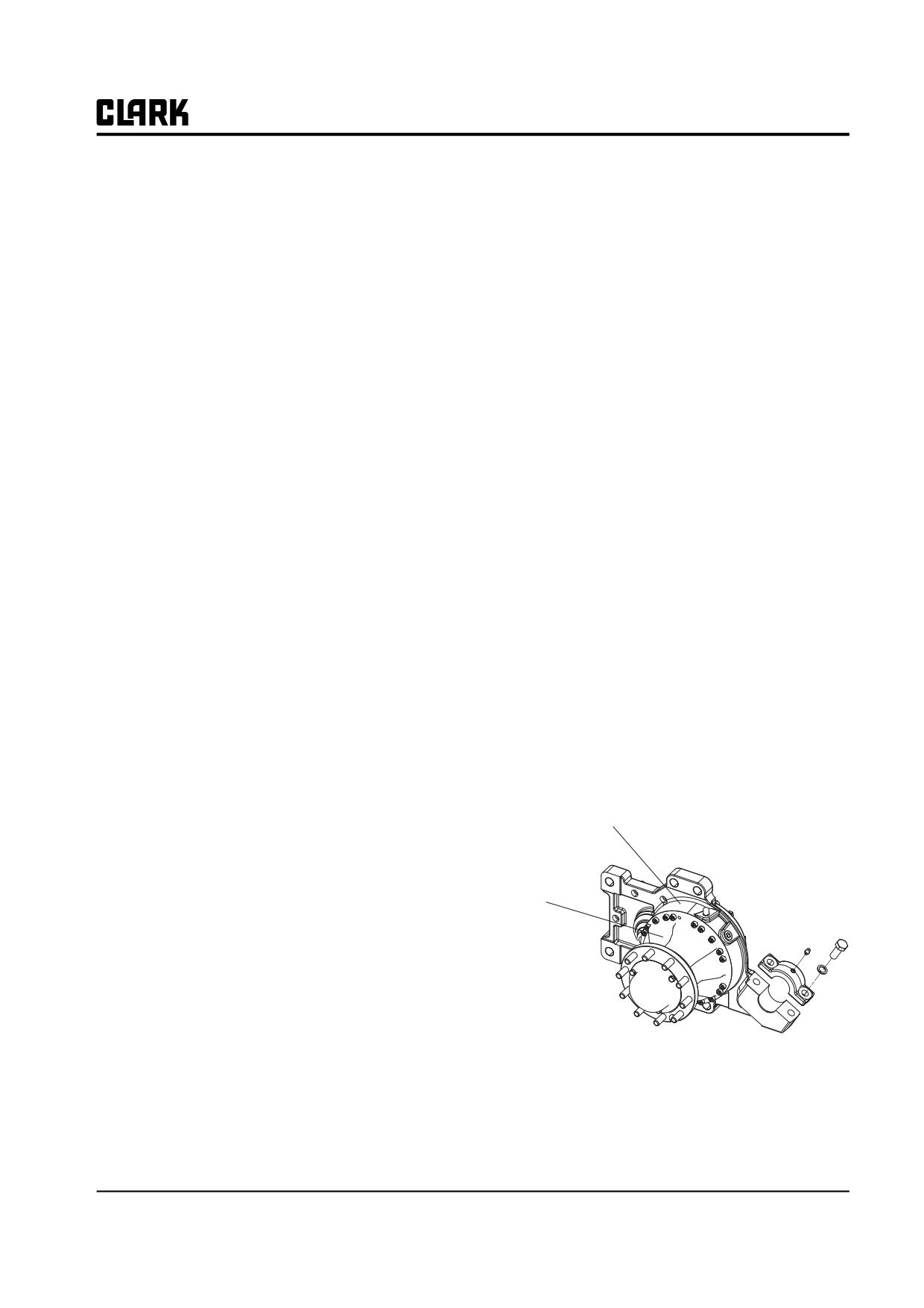
Group 20, Drive Axle
Section 1
Specification and description of drive axle
Specifications
Torque specification
General specification
Boss bearing and plate housing socket bolt, tightening
Reduction ratio
:
26
torque : (330 kgf.cm) 12T
Speed
:
Forward/Reverse 1
Brake piston and plate housing socket bolt, tightening
Oil capacity
:
1.0 liter
torque : (130 kgf.cm) 8T
Gear type
:
Plant gear
Brake stopper fixing socket bolt, tightening torque: (130
kgf.cm)
Drive axle oil
:
Torque fluid 56(SAE 80W)
Wheel bearing free load adjusting nut, tightening torque :
Weight
:
60kg (excl. oil)
(2000 kgf.cm)
Final housing socket bolt, tightening torque : (330 kgf.cm)
12T
Brake specification
Wheel cap fixing socket bolt, tightening torque : (330
Service brake type
:
Wet brake
kgf.cm) 12T
Required flow of service brake: 3.9cc
Master hinge mounting bolt: M16X2.0X40
Service brake setting stroke: 0.9mm
Brake oil
:
Hydraulic fluid
DESCRIPTION
Parking brake lever ratio :
1:8.27
Drive axle ass'y
Fitting specification
Brake port
: M10X1.0P
Oil drain plug
: PT 1/4, PT 3/8
Wheel Ass'y
Air bleeder
: PT 1/8
Air bleeder (Brake): M12X1.25P
Oil port
: PT1/2
Nipple
: M6X0.75P(grease)
Stud bolt (Wheel bolt): M14X1.5P
Loctite specification
Bolt
:
Loctite 277
Fitting
:
Loctite 572
SM 765, Nov ’06
Specification and description of drive axle • 20-1-1
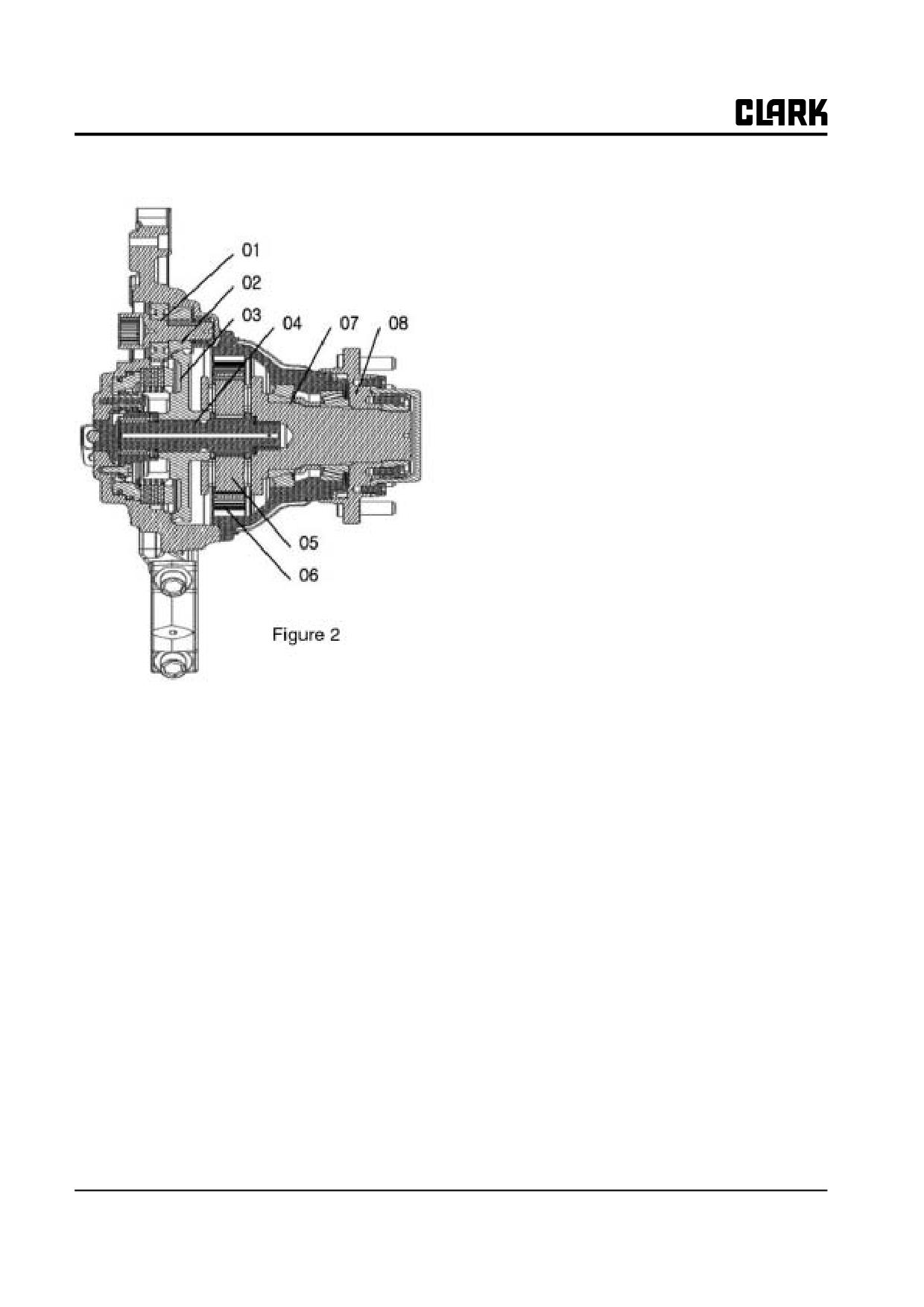
Group 20, Drive Axle
Drive axle
As this drive axle is power transmission system that is
installed to driving wheel for electric forklift, it includes
service brake and parking brake systems. It transmits the
rotating force from the driving motor to the drive
shaft(01). The gear(03) meshed in drive gear(02), which is
locked to the shaft with key, and the sun gear shaft(04) are
one body type as locking with key. The sun gear shaft(04)
and the planetary gear(05) are meshed in the ring
gear(06), so that the third reduction will be occurred. The
final reduced rotating force will be applied to wheel
adapter(08) through the carrier shaft(07) in order to rotate
the shaft.
20-1-2 • Specification and description of drive axle
SM 765, Nov ’06
Group 20, Drive Axle
Section 2
Troubleshooting of wheel drive axle
Troubleshooting for wheel drive axle
Maintenance period
Following contents help to solve the problem of wheel
• Replacement period of wheel drive axle oil: 1,000
drive axle that does not perform right functions.
hours
• Wheel drive axle oil volume: 1.0 liter
Please make sure that the wheel drive axle is just a key
part of related power train components group, when han-
• Replacement period of service brake disc: 4,000
dles the problem of wheel drive axle. The wheel drive axle
hours
is in normal operation based on the condition of other
related components of power train. Therefore, examine
the problems and maintain the wheel drive axle oil, wheel
drive axle assembly, control system, brake system and
driving motor to be the perfect system.
To check and repair the defectiveness of wheel drive axle,
please refer to the description based on the symptom and
cause.
For the inspection of doubtable components, please refer
to the maintenance manual.
Symptom and Cause
Following is general defectiveness of wheel drive axle and
possible causes.
When the forklift does not move.
• Poor contact of battery.
• Check the operational condition of parking brake
• Check the electric control system
• Check the direction-control switch
• Check the connecting unit of connector
• Check the normal operation of driving motor
• Check the condition of bearing
When the forklift is overheated
• Check if the oil level is low or is polluted
• Check the overloading of fork
• Check the condition of bearing
• Check if there is dragging to service brake
SM 765, Nov ’06
Troubleshooting of wheel drive axle • 20-2-1
NOTE :
Group 20, Drive Axle
SM 765, Nov ’06
Group 20, Drive Axle
Section 3
General operation of drive axle
General operation
Cleaning of part
Following procedure shall be applied to disassembly,
Do not use gasoline because it is very combustible. It is
inspection, washing, repair, installation and assembly pro-
also not safe to the working environment.
cess of wheel drive axle component. Especially, disas-
To complete the disassembly, appropriate cleaning is
sembly and reassembly procedures are described at the
required.
latter part of this section. Those procedures have to be
observed.
Clean the processing surface of steel part with industrial
solvent.
Disassembly of components
Wash out inside and outside of bearing, cap and housing.
Before disassemble the wheel drive axle, drain out the
It is possible to clean the unprocessed or unpolished cast
wheel drive axle oil, remove the required hydraulic line
iron part with steam.
and take off the wheel drive axle from the forklift as illus-
Treat the part or cast iron that is being washed by solvent
trated to the manual to disassemble the wheel drive axle.
or steam at the light alkali liquid tank. Complete dry the
Please observe followings.
part before rinsing.
Cleanness - Work at the clean place. Make sure that
For the part with rough surface like castings, do not clean
impurities or dirt should not get into the unit while repair-
with dust cloth.
ing. The bearing can be worn and damaged by the dirt.
Before start the disassembly, always keep clean the out-
Rinse all parts completely. Clean all part except rough-
side of unit.
surfaced part with clean cloth and dry it. Slightly apply
the oil to the part and wrap it with anti-corrosive paper for
Assembly - When disassemble many assemblies, place all
store. Keep it to clean and dry place.
parts with the same order of disassembly on the clean
bench. It makes the assembly simple and there is no
Until the bearing gets clean, wash out with clean solvent.
chance to lose the part.
When dry the bearing with compressed air without mois-
ture, make sure that the bearing does not get out of its
Use of part-disassembly tools
- Always control the
place or damaged because of compressed air.
load that is applied to the shaft, bearing and housing. The
removal of these parts is limited. Never apply the power to
Do not rotate the bearing while drying. It is no problem to
drive the parts when they are completely stopped. For
slowly rotate it with hands for faster dray.
removal, it is recommended to use soft hammer, bar and
NOTE
wooden hammer.
Do not wash out the emulsion product with
Bearing - Use designated puller when takes off the reus-
solvent.
able bearing. Apply the clean oil to bearing and cover it
with clean cloth without fuzz or clean paper when store it.
Part checking
Snap ring - Take off the snap ring with designated pliers.
Check all wheel drive axle components before reassemble
This snap ring is reusable if there is no groove and it is not
after cleaning, and decide it if it needs to be replaced.
loosened.
It is important to carefully and completely check all parts.
When replace all he parts that seem to be worn, stressed or
damaged, it saves money and time.
SM 765, Nov ’06
General operation of drive axle • 20-3-1
Group 20, Drive Axle
Checking: Check the steel part if there is mark, deforma-
When it needs to be replaced, use official product of
tion or discoloration that is related to inappropriate lubri-
CLARK to maintain the unit performance and extend the
cating work, notch, and step or scratch.
life.
Check the fitting, discoloration and broken area of bearing
The checking procedure that is advised to various parts is
ball, cage or retainer, roller and raceway
as follows.
Check the abnormal contacting pattern of gear that has
serious symptom of abrasion, fitting and crack across to
Bearing
the contacting line.
Replace the bearing if there is hole or it is broken or dis-
Check the crack, scratch and abrasion of processed sur-
colored. Always replace one set of bearing cup and cone.
face for casting or malleable parts, wider drill hole and
Do not separately replace the bearing and race.
crack or burr of contacting surface.
Replace the bearing with considerable gap.
Check the fastener if it has rounded head or damaged spi-
Check the fitting of bearing. The internal race of bearing
ral area or is curved or cracked.
has to be firmly inserted into the shaft. Tighten the outer
IMPORTANT
race to the housing bore. If the bearing gets out from the
All damaged parts that affect to the align-
bore, replace the housing.
ment and structure should be replaced. The
repair with welding or correction is not
Gear and Shaft
allowed. These works can cause the malfunc-
tion when the load is applied because it
Check the frosting and fitting of gear tooth. The frosting
affects the housing of casting product.
on the tooth surface of gear does not affect to the malfunc-
Curved head, crack or leakage, loosen stud,
tion of transmission. When continuously uses unit, the
crossed-type screw hole of all housings
frosting of gear won't be developed to the fitting condi-
tion. Most likely, the gear tooth that is a little bit fitted can
be reusable. However, if the fitting is serious, the gear has
Repair and replacement of part
to be replaced.
Protect the wheel drive axle such as seal and washer from
If it is possible to use Magnaflux, check the damage of
the early abrasion, and replace it with low-priced parts
part with it.
that do not give big cost of repair.
If the heat-treated part of gear tooth is worn or cracked,
Replace the seriously worn part even though it is not bro-
replace the gear.
ken.
Check all shafts if the tooth is curved or cracked or the
The steel parts such as shaft or gear can't be repaired. If it
spline is broken.
is worn or damaged, it should be replaced.
The seal and washer has to be periodically replaced. For
Spline
the fastener with auto-locking patch, it is possible to reuse
if it is fixed by dropping the heavy duty thread locker for
Check the abnormal abrasion from the spline of all gear
many times.
and shaft. If the spline is excessively worn or fitted,
replace the relevant part.
The repair of wheel drive axle housing is limited to the
removal of scratch or burr on the processing surface or
replacement of damaged stud. Because the cost of new
O-Ring
part is very small in comparison to the total cost of labor
power and malfunction time of machine and it may
Replace all O-ring whenever overhauling. Lubricate the
require more cost after the repair, it is better avoiding the
O-ring and seal with gear oil before the reassembly.
reuse of the damaged parts. To decide reuse or replace-
ment of drive axle part, the internal force, time to use and
application of unit shall be considered.
20-3-2 • General operation of drive axle
SM 765, Nov ’06
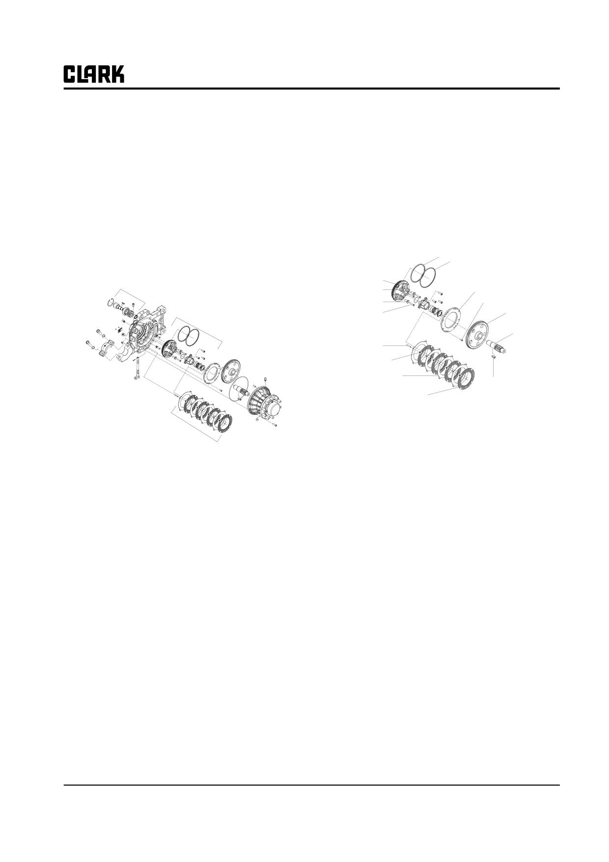
Group 20, Drive Axle
Section 4
Disassembly and Reassembly of drive axle
Disassembly of drive axle ass'y
Disassembly of service brake
D-ring
Cautions to disassemble the drive axle
D-ring
Drive shaft assembly
Piston
Stopper brake
Mounting plate
Return spring
Spacer
Socket bolt
Service brake piston
Driven gear
Hexagon bolt
Shaft sun gear
Driven assembly
Guide pin
Return spring
Mast hinge
Reaction plate
Key
Parking lever
Paper disc
• Remove the shaft sun gear and driven gear from
the bearing bore.
Disc and plate set
• Remove twelve stopper fixing socket bolts with
Wheel assembly
relevant tools.
• Arrange the parts under the order of disassembly.
• Remove the reaction plates (4EA) and the brake
• Pay attention to the parts and removal order when
discs (4EA) from the housing.
disassemble.
NOTE
• Record with irremovable pen if necessary and dis-
Pay attention not to lose or damage the
tinguish the parts.
springs (16EA).
• Place the disassembled units to the clean area. Dis-
assembly of service brake
• Remove the piston fixing hexagon bolts from the
housing by using spanner or wrench box.
NOTE
When remove the piston, apply the air pres-
sure into the brake port.
SM 765, Nov ’06
Disassembly and Reassembly of drive axle • 20-4-1
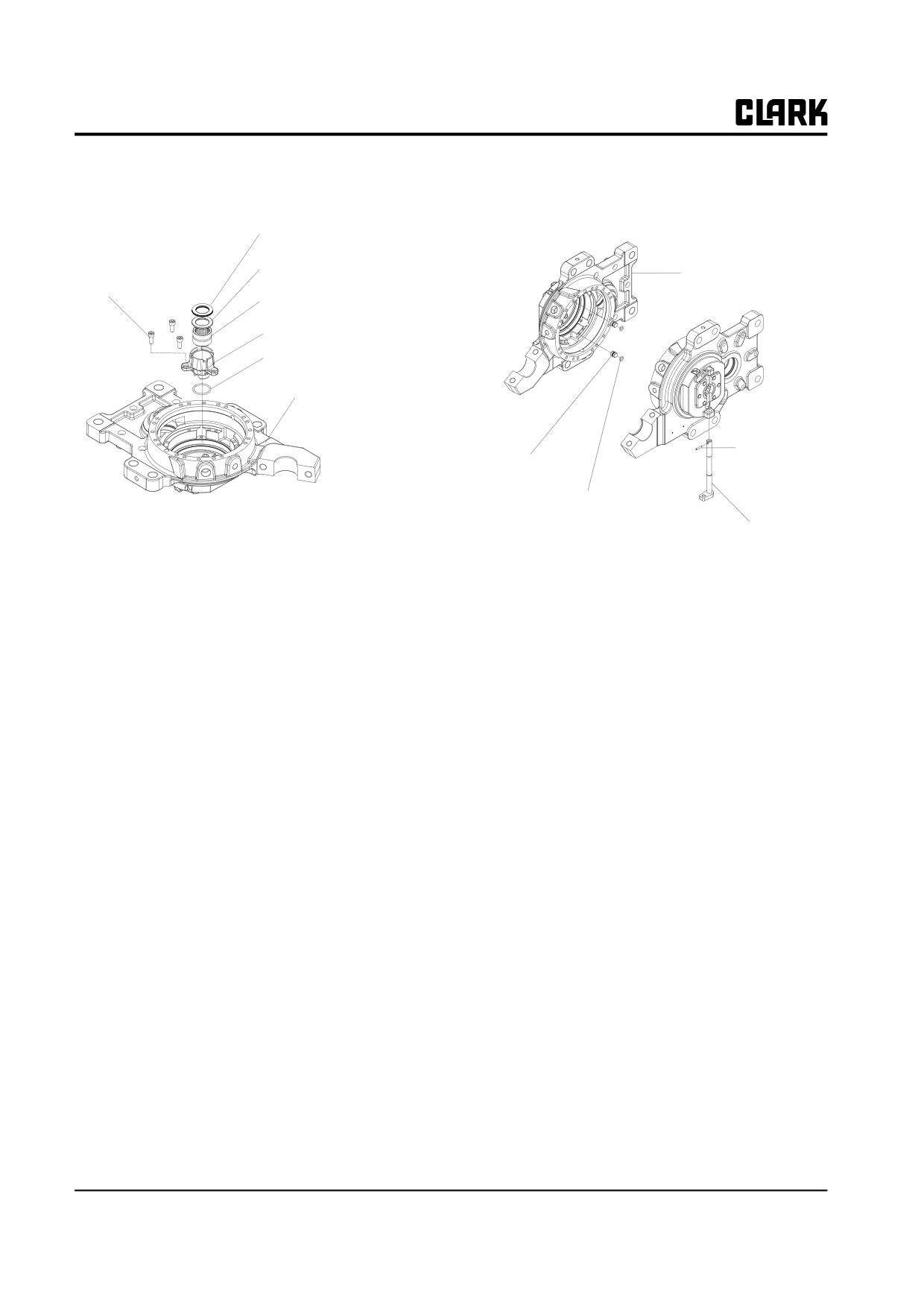
Group 20, Drive Axle
Disassembly of bearing boss
Disassembly of parking lever and
drive shaft
Thrust needle bearing
Spacer (shim)
Housing plate
Bolt
Needle roller bearing
Bearing boss
O-ring
Plate housing
Pin spring
King brake pin
O-ring
Parking brake lever
Disassembly of bearing boss
Disassembly of parking brake lever and
•
Remove the thrust needle bearing and shim from
the bearing boss.
drive shaft
•
Remove the bearing boss fixing bolts (3EA) from
• Remove the spring pin by using pliers.
the plate housing with appropriate tool.
• Remove the parking brake pin and O-ring from the
•
Pay attention to the damage or separation of O-
plate housing by using rubber hammer and screw
ring from bearing boss.
driver.
NOTE
NOTE
When reassembly, use new O-ring.
Pay attention not to damage the O-ring of
parking brake pin.
•
Remove the parking brake lever from the plate
housing.
20-4-2 • Disassembly and Reassembly of drive axle
SM 765, Nov ’06
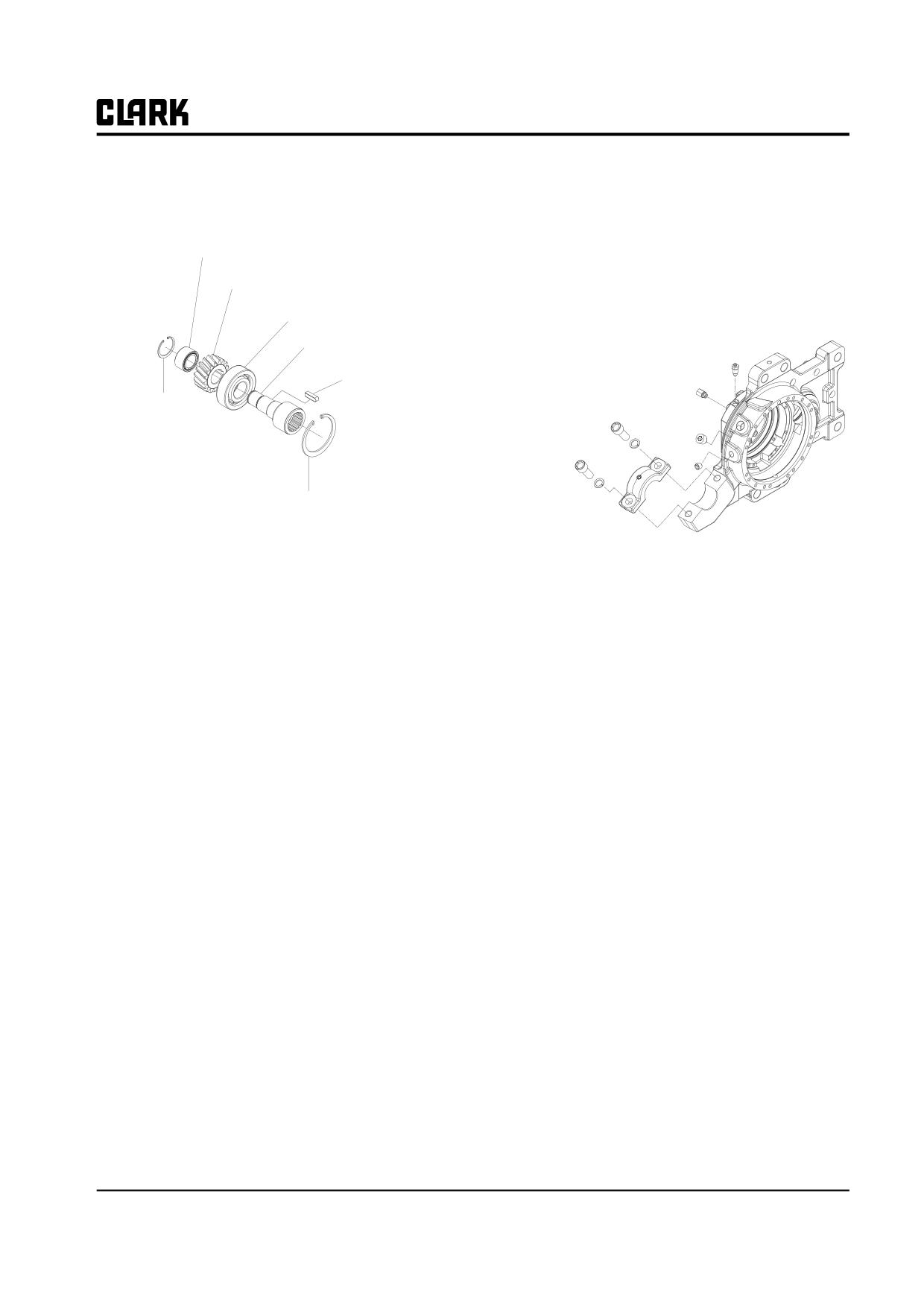
Group 20, Drive Axle
Disassembly of drive shaft ass'y
Disassembly of master hinge,
brake fitting and plug
Bearing
Brake air bleeding port
Gea(13T)
Brake port
Bearing
Plug
Drive shaft
Level plug
Key
Bolt
Snap ring
Snap ring
Master hinge
•
Remove the snap ring from the drive shaft.
•
Remove the gear (13T) and key from the drive
shaft.
Disassembly order of brake fitting and plug
•
Remove the ball bearing from the drive shaft by
using gear puller.
•
Remove the master hinge fixing socket bolts
(When install the gear puller, fix it to inner ring of
(2EA) from plate housing by using appropriate
bearing and remove it)
tool.
•
Remove the fittings of brake port and brake air
bleeding port.
•
Remove the level plug and insertion plug.
SM 765, Nov ’06
Disassembly and Reassembly of drive axle • 20-4-3
NOTE :
Group 20, Drive Axle
SM 765, Nov ’06
Group 20, Drive Axle
Section 5
Disassembly and Reassembly of axle end
NOTE
Disassembly of carrier and hub bear-
Arrange all the parts under the order of dis-
ing
assembly.
Pay attention to the parts and removal order
when disassemble.
Plant gear shaft
Record with irremovable pen if necessary
Pin spring
and distinguish the parts.
Taper roller bearing
Spacer
Housing final
Removal of axle end from the drive axle
Bearing taper
Oil seal
Bolt stud
Adaptor
Washer
Needle bearing
Planetary gear
Spacer
Lock nut
Washer
O-ring
Lock washer
Wheel cap
Lock nut
Bolt
Remove hexagon socket bolts from the plate housing by
using appropriate tool to disassemble the wheel assembly
and drive axle.
SM 765, Nov ’06
Disassembly and Reassembly of axle end • 20-5-1
Group 20, Drive Axle
Disassembly of axle end
Disassembly of carrier shaft ass'y
Taper roller bearing
Spacer
Housing final
Taper roller bearing
Oil seal
Stud bolt
Adaptor
Stud bolt
Lock nut
O-ring
Wheel cap
Bolt
Disassembly of wheel sub assembly
Disassembly of carrier shaft ass'y
•
Remove the wheel cap fixing socket bolts (4EA)
•
Set the carrier shaft ass'y on the flat bottom place.
from the wheel adaptor with appropriate tool.
•
Remove the planetary gear shaft fixing pin spring
•
Remove the fixing bolts of lock nut.
by using pliers or tool.
•
Remove the lock nut fixed to the wheel adaptor
•
Remove the planetary gear shaft by tapping two or
from the carrier shaft.
three times with hammer or tool.
•
Remove the wheel adaptor from the carrier shaft.
• -Repeat the removal to three places.
NOTE
!
CAUTION
Pay attention not to do damage the oil seal
assembled to the wheel adaptor.
When reassemble, the pin spring can be
omitted.
•
Place the axle end on the press and remove the
Check if the pin spring is assembled when the
taper roller bearing.
assembly is completed.
The way to assemble the oil seal: Use jigDisassembly of
carrier shaft ass'y
20-5-2 • Disassembly and Reassembly of axle end
SM 765, Nov ’06
Group 20, Drive Axle
Section 6
Adjustment
• Re-measure the assembly product with dial gauge.
Preloading and adjustment of hub
• When compare the measured value with gauge, if
taper roller bearing
the space is plus value based on the gap, insert
Lock nut
spacer with small width and if it is minus value,
insert the space with big width. Apply different
spacer based on the measured value.
Measuring master
Lock nut
Oil Seal
Taper roller
bearing
Spacer
Carrier ass'y
Required tool for assembly
- Lock nut assembly adaptor
- Torque wrench, 20kgf.m setting
-
(-) Screwdriver
− Rubber hammer
Adjustment order of preloading
•
Place the bearing cup into final housing and press-
How to measure the space
fit it to the housing with assembled jig.
Measurement when the space isn't assembled
•
Locate the measuring spacer as shown in the
•
Use measuring master to measure the space.
above figure.
(Refer to the figure 14 for measurement of space)
•
Press-fit the outer ring of bearing to the housing.
•
Place the taper roller bearing as shown in the fig-
•
Assemble the taper roller bearing to carrier shaft,
ure 15.
set the preload adjustment nut up to 2000kgf.m and
measure and record with dial gauge.
•
Press-fit the bearing with press and pressurizing
jig.
•
Hit it with plastic hammer and rotate the wheel
Measurement when the space is assembled
adaptor two or three times.
• Assemble the spacer based on the above method
Set the torque value by tightening the preloading
and apply the preload.
adjustment nut.
(Torque wrench, torque setting: 20kgf.m)
SM 765, Nov ’06
Adjustment • 20-6-1
Group 20, Drive Axle
•
Tighten the bolt to prevent the looseness.
•
Install the jig for measurement to contact on the
disc and plate housing surfaces.
•
Measure the preloading value with push-pull
gauge as shown in the figure 16.
•
Place the dial gauge on the jig.
(Specification: Push-pull gauge torque: 12kgf.cm
•
Measure the stage differences between jig sur-
~15kgf.cm)
faces.
(Caution: measure it when apply the preload to
brake disc[150kg.cm])
•
The gap when the deviation of dial gauge is "0".
(It accurately sets to 0.9mm)
•
Set the gap adjustment according to the measured
value of gap based on the thickness of back plate.
•
Refer to the specification to set the stroke.
•
When measuring gap is based on 0.9mm, if it is
plus value, apply the thicker plate.
•
When measuring gap is based on 0.9mm, if it is
minus value, apply the thinner plate.
Measured value and stroke specification
Measured value
Setting stroke
-0.15
0.95
-0.10
0.9
-0.05
0.85
0
0.8
0.05
0.75
Adjustment of brake disc gap
0.1
0.7
0.15
0.65
Specification: 0.85~0.9mm
Required tool for setting
- Measuring jig
- Dial gauge
Preloading adjustment order
•
Assemble the disc and plate to the plate housing.
20-6-2 • Adjustment
SM 765, Nov ’06
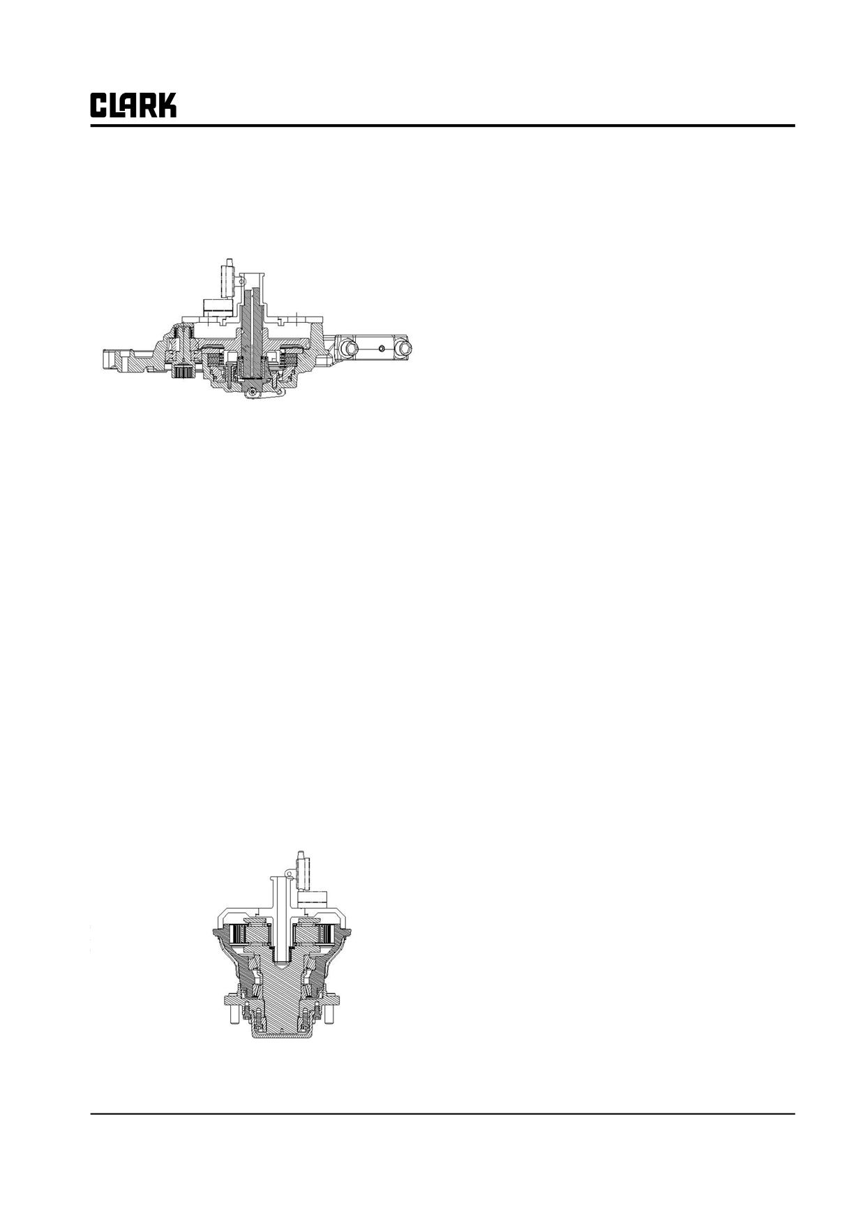
Group 20, Drive Axle
•
Record the value that the dial gauge shows.
Adjustment of thrust needle bear-
•
Calculate the stage differences of drive axle and
ing gap
wheel, and set the gap of shaft direction.
•
Set the thrust needle bearing based on gap specifi-
cation.
(Specification : 0.05~0.1mm)
Calculation of measured value and shim
adjustment
•
Adjust it by summing the measured values of
wheel and drive axle and deducting the existing
shim (3t).
•
If the summed value is "0", set the gap with
0.1mm.
Apply the different spacer based on the measured
Figure 18. Drive axle assembly
value (for example, 3T, 3.1T, 3.2T)
Required tool for setting
- Measuring jig
- Dial gauge
How to measure the gap
•
Install the assembled axle ass'y to the exclusive jig
or flat bottom.
•
Set the measuring jig as shown in the figure 18.
•
Place the dial gauge on the measuring jig and mea-
sure the stage differences of jig.
•
Record the value that the dial gauge shows.
•
Install the assembled wheel ass'y to the exclusive
jig or flat bottom as above method.
• Set the measuring jig to axle end assembly as
shown in the figure 19.
Figure 19. Axle end assembly
SM 765, Nov ’06
Adjustment • 20-6-3
NOTE :
Group 20, Drive Axle
SM 765, Nov ’06
GROUP 22
GROUP 22
WHEELS AND TIRES
Wheels and Tires Specifications and
Description
Section 1
Pneumatic Wheels and Tires
Section 2
SM 765, Nov ’06
Group 22, Wheels and tires
NOTE :
Group 22, Wheels and tires
SM 765, Nov ’06
Group 22, Wheels and Tires
Section 1
Wheels and Tires Specifications and Description
Specifications
Description
Steer Tire Types : Pneumatic rubber/Cushion rubber, non-
The wheels and tires used on the truck come in pneumatic
marking, and urethane.
or cushion types in a variety of sizes depending on truck
model and application. Pneumatic tires are mounted on
Drive Tire Types : Pneumatic rubber/Cushion rubber, non-
multi-piece rims with locking rings.
marking, and urethane.
Pneumatic Drive and Steer Tire Inflation Pressure :
!
WARNING
Drive GEX20/25/30: 800 kPa (116psi)
For your safety and the safety of others,
before you do tire or rim maintenance or ser-
Steer GEX20/25/30: 1000 kPa (145psi)
vice, read the OSHA rules regarding owner
responsibility. Do not work on tires or rims
Fastener Torques
unless you have been trained in the correct
procedures. Read and understand all mainte-
Steer Tire Mounting Nut Torque : Check mounting proce-
nance and repair procedures on tires and
dure in Sections 2 and 3 for cushion and pneumatic tires
rims. Serious injury or death can result if
and wheels.
safety messages are ignored.
Drive Wheel Mounting Nut Torques :
1 Piece (black) 155-180 N⋅m (114-133 lb⋅ft)
The Occupational Safety and Health Act (OSHA) speci-
fies required procedures for servicing multi-piece rim
wheels in 29 CFR Section 1910.177. It is the owner’s
Service Intervals
responsibility to comply with OSHA.
Wheel Mounting Bolts Check and Tightening : Every 50-
In accordance with OSHA, the owner must provide a
250 hours of operation and each PM.
training program to train and instruct all employees who
service multi-piece rim wheels in the hazards involved
Tire Condition : Daily inspection.
and the safety procedures to be followed. Do not let any-
Tire Pressure Check : Daily inspection.
one mount, demount, or service multi-piece rim wheels
without correct training.
The owner should obtain and maintain in the service area
current copies of the United States Department of Trans-
portation, National Highway Traffic Safety Administra-
tion publications entitled “Safety Precautions for Mount-
ing and Demounting Tube-Type Truck/Bus Tires,” and
Multi-Piece Rim/Wheel Matching Chart” or other similar
publications applicable to the types of multi-piece rim
wheels being serviced.
SM 765, Nov ’06
Wheels and Tires Specifications and Description • 22-1-1
NOTE :
Group 22, Wheels and Tires
SM 765, Nov ’06
Group 22, Wheels and Tires
Section 2
Pneumatic Wheels and Tires
in this manner can result in damage to the rim and
! CAUTION
truck tip-over and driver injury.
SAFE PARKING. Before working on truck :
4.
Do not fill a tire with air that has been run flat with-
1. Park truck on a hard, level, and solid
out first inspecting the tire, rim, and wheel assembly.
surface, such as a concrete floor with no
Double check the lock ring for damage. Make sure
gaps or breaks.
that it is secure in the gutter before filling the tire
with air.
2. Put upright in vertical position and fully
lower the forks or attachment.
5.
Always remove all air from a single tire and from
both tires of a dual assembly prior to removing any
3. Put all controls in neutral. Turn key switch
rim components, or any wheel components, such as
OFF and remove key.
nuts and rim clamps. Always remove the valve core
4. Apply the parking brake and block the
to remove air from tire. Be sure all air is removed.
wheels.
6.
Check rim components periodically for fatigue
cracks. Replace all cracked, badly worn, damaged,
Pneumatic Tire Maintenance
and severely rusted components.
Precaution
7.
Do not, under any circumstances, attempt to rework,
weld, heat, or braze any rim components that are
The following instructions supplement the OSHA require-
cracked, broken, or damaged. Replace with new parts
ments. In the event of any conflict or inconsistency
or parts that are not damaged, which are of the same
between these instructions and the OSHA requirements,
size, type, and make.
the OSHA requirements shall be controlling.
8.
Never attempt to weld on an inflated tire/rim assem-
bly.
! WARNING
Before you do tire or rim maintenance, read
9.
Clean rims and repaint to stop detrimental effects of
the OSHA rules regarding owner responsib-
corrosion. Be very careful to clean all dirt and rust
lilty. Read and understand all maintenance
from the lock ring gutter. This is important to secure
and repair procedures on tires and rims. Do
the lock ring in its proper position.
not work on tires or rims unless you have
A Filter on the air filling equipment to remove the
been trained in the correct procedures. Seri-
moisture from the air line prevents a lot of corrosion.
ous injury or death can result if the safety
The filter should be checked periodically to make
messages are ignored.
sure it is working properly.
10.
Make sure correct parts are being assembled. Ask
1. Do not let anyone mount or demount tires without
your distributor or the manufacturer if you have any
proper training.
doubts.
2. Never sit on or stand in front of a tire and rim assem-
11.
Do not be careless or take chances. If you are not
bly that is being filled with air. Use a clip-on chuck
sure about the proper mating of rim and wheel parts,
and make sure the hose is long enough to permit the
consult a wheel and rim expert. This may be the tire
person filling the tire with air to stand to the side of
man who is servicing your fleet, the rim and wheel
the tire, not in front or in back of the tire assembly.
distributor in your area, or the CLARK dealer.
3. Never operate a vehicle on only one tire of a dual
12.
Mixing parts of one manufacturer’s rims with those
assembly. The carrying capacity of the single tire and
of another is potentially dangerous. Always ask man-
rim is dangerously exceeded, and operating a vehicle
ufacturer for approval.
SM 765, Nov ’06
Pneumatic Wheels and Tires • 22-2-1
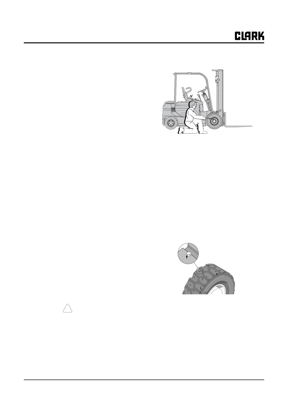
Group 22, Wheels and Tires
13. Do not use undersized rims. Use the right rims for
handled gauge to keep your body away from
the job.
the side.
14. Do not overload rims. Ask your rim manufacturer if
special operating conditions are required.
15. Do not seat rings by hitting with a hammer while the
tire is filled with air pressure. Do not hit a filled or
partially-filled tire/rim assembly with a hammer.
16. Double check to make sure all the components are
properly seated prior to filling tire with air.
17. Have the tire in a safety cage when filling with air.
18. When removing wheels, regardless or how hard or
firm the ground appears, put hardwood blocks under
the jack.
• If tires are low, do not add air. Have the tire and
wheel inspected by a person trained and autho-
19. Block the tire and wheel on the other side of the vehi-
rized to do tire and wheel maintenance. The tire
cle, before you place the jack in position. Place
may require removal and repair.
blocks under the truck frame as near as possible to
• Incorrect (low) tire pressure can reduce the sta-
the jack to prevent the truck from falling if the jack
bility of a lift truck and cause it to tip over.
should fail.
IMPORTANT
20. Remove the bead seat band slowly to prevent it from
Check wheels and tires for damage every
dropping off and crushing your toes. Support the
time you check tire pressure. Make repairs
band on your thigh and roll it slowly to the ground.
when needed. Dirt can get into cuts and cause
This will protect your back and feet.
damage to the tire cord and tread. Remove
21. Bead breakers and rams apply pressure to bead
debris from all cuts.
flanges. Keep your fingers away from the bead
flanges. Slant bead breaker about 10° to keep it
2.
Check the condition of the drive and steer wheels and
firmly in place. If it slips off, it can fly with enough
tires. Remove objects that are imbedded in the tread.
force to kill. Always stand to one side when you
Inspect the tires for excessive wear, cuts and breaks.
apply hydraulic pressure.
General Tire Maintenance, Inspec-
tion, and Repair
1. Park the truck as described in “Safe Parking” and
check for correct tire inflation air pressure.
• Drive GEX20/25/30: 800 kPa (116psi)
• Steer GEX20/25/30: 1000 kPa (145 psi)
3.
Check all wheel lug nuts or bolts to be sure none are
loose or missing. Have missing bolts replaced and
! CAUTION
loose bolts tightened to the correct torque before
Check tire pressure from a position facing
operating the truck.
the tread of the tire, not the side. Use a long-
• Torque pneumatic steer tires to 225-250 N⋅m (165-
185 ft⋅lb).
• Torque 1 piece black lug nuts for pneumatic drive
tires to 155-180 N⋅m (114-133 ft⋅lb).
22-2-2 • Pneumatic Wheels and Tires
SM 765, Nov ’06
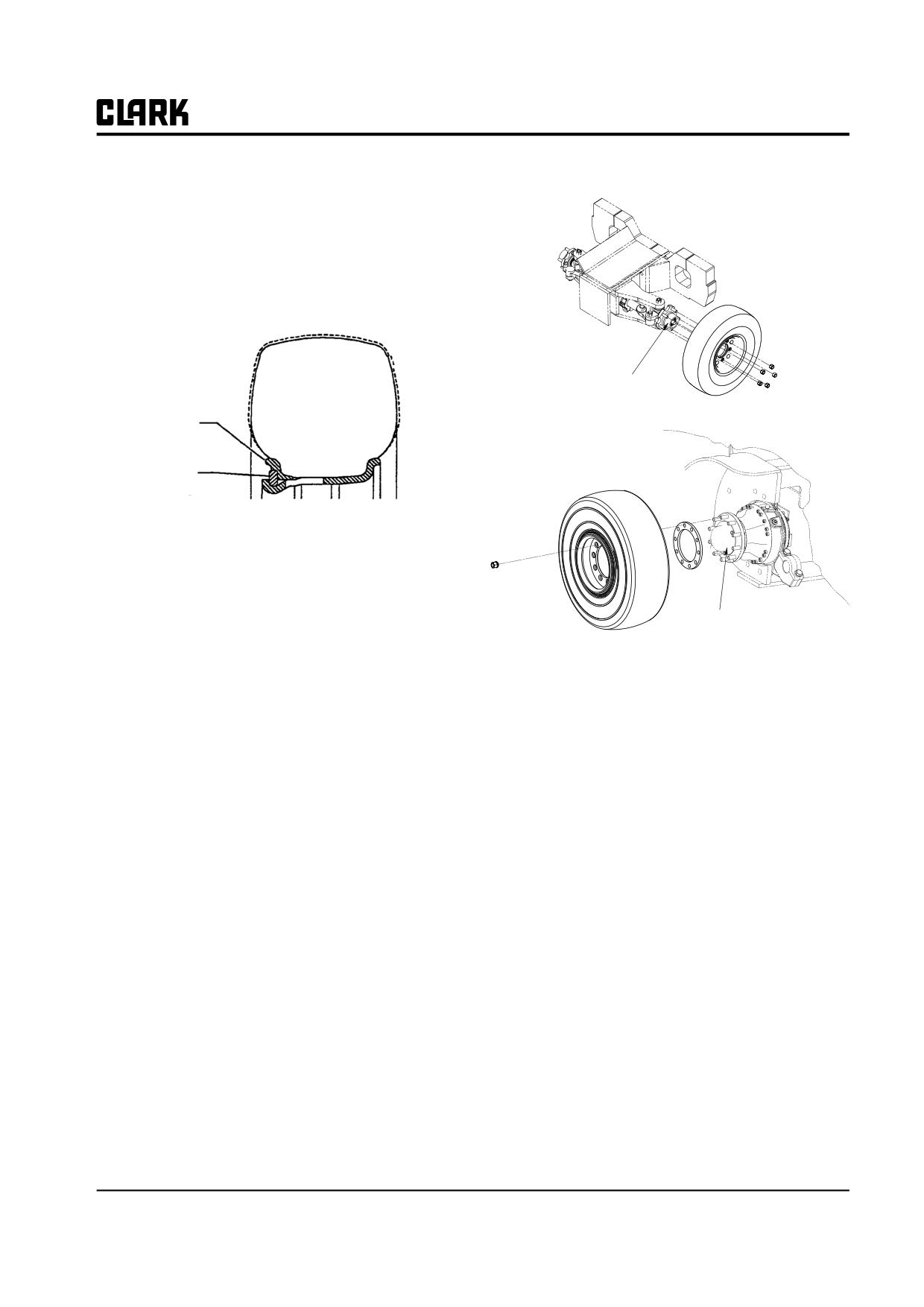
Group 22, Wheels and Tires
Inspection and Minor Repair
2. Loosen the five lug nuts on the wheel.
Inspect pneumatic tires and wheels carefully for.
1. Low inflation pressure.
2. Damaged tires. Check tires for cuts and breaks.
3. Damaged wheels or loosening of the lock ring on
multi-piece rims.
Steering
Axle hub
Wheel
wedge
Lock
ring
4. Check for loose nuts or bolts not in position.
5. Check the nuts or bolts for damage.
6. Check the surface of the wheels for bent flanges.
7. Check all parts for rust or corrosion.
Drive
Axle hub
8. Mark the damaged areas with chalk so that the parts
can be removed from operation.
3. Use a portable jack of adequate capacity placed
9. Remove all parts that are damaged and install new
under the frame of truck to raise drive or steer wheels
parts in the same position.
off floor.
10. Replace parts with the correct sizes and types. See
4. Once tire is off the ground enough to rotate freely,
your parts manual.
remove the lug nuts and lift the wheel from the hub.
Use caution when lifting tire and wheel.
11. Include your truck serial number when ordering
replacement parts.
Drive and Steer Wheel Remounting
Wheel Dismounting and Remounting
IMPORTANT
See “Tire Installation” in this Section to
Refer to “Lifting, Jacking, and Blocking” in Group SA for
make sure the wheel and tire mounting orien-
information on jacking up or raising the truck for wheel
tation is correct. Check the information for
removal. Always start with the truck parked safely.
correct tire-to-wheel mounting and wheel-to-
hub mounting.
Drive and Steer Wheel Dismounting
1. Make sure the truck is parked on a flat, hard surface
1. Remove the valve core from the valve stem to be sure
and the jacking and blocking devices are secure to
all air is removed from the tire.
hold the truck in a safe position.
2. Inspect the removed lug nuts for damage to the
threads. Also inspect all hub studs for thread damage.
SM 765, Nov ’06
Pneumatic Wheels and Tires • 22-2-3
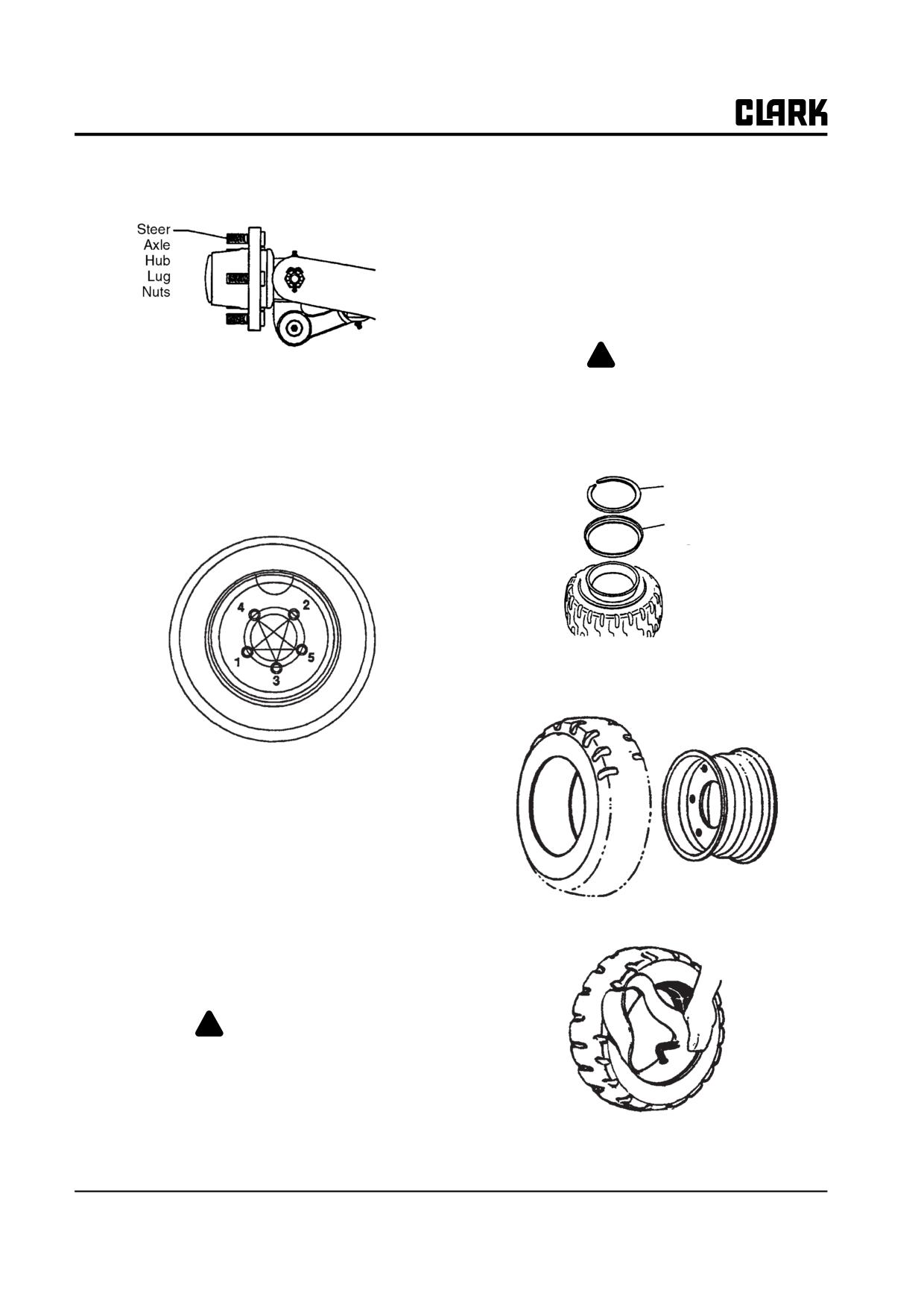
Group 22, Wheels and Tires
Replace any lug nuts or studs that have damaged
the rim and side ring. The lock ring can sepa-
threads. Make sure studs are secure in the axle hub.
rate from the rim with enough force to cause
injury or death.
Wheel Disassembly and Tire Removal
1. Remove valve core from the valve stem to be sure all
air is removed.
!
WARNING
3. Set the wheel on the hub and start the lug nuts on the
Before starting disassembly, remove the air
hub studs. Tighten the nuts only enough to seat the
from the tire. Failure to remove the air from
nuts into the beveled openings on the wheel and to
the tire can result in serious injury.
secure the wheel on the axle hub.
4. Use a crisscrossing nut tightening sequence to torque
2. Remove lock ring.
the nuts to a pre-final torque of 54-81 N⋅m (40-60
Lock Ring
ft⋅lb). Make sure all nuts seat into beveled spacer
holes correctly.
Wheel
Wedge
3. Remove wheel wedge.
4. Remove tire from wheel.
5. Begin the crisscrossing sequence again and tighten
the lug nuts to final torque.
• Torque drive wheel 1 piece lug nuts to 155-180
N⋅m (114-133 ft⋅lb).
• Torque steer wheel lug nuts to 225-250 N⋅m
(165-185 lb⋅ft).
6. Carefully lower the truck and remove the jack.
7. Check tire pressure for correct inflation pressure.
• Drive wheel pressure is
5. Remove the rubber inner tube protector (flap).
GEX20/25/30: 800 kPa (116psi)
• Steer wheel pressure is
GEX20/25/30: 1000 kPa (145 psi).
! WARNING
If tires are not fully inflated, see “Adding Air
Pressure To Mounted Wheel/Tire Assem-
blies” and follow the procedures for adding
air to the mounted tires.
Before you add air pressure to the tire, make
6. Repair tire and/or tube, as needed.
sure the lock ring is correctly positioned in
22-2-4 • Pneumatic Wheels and Tires
SM 765, Nov ’06
Group 22, Wheels and Tires
7. Check for cracks in the wheel.
12. Clean the tire bead seat area. Remove all rust and
rubber with a wire brush or wheel.
Cracks in the wheel are caused by :
• Deep rim tool marks.
13. Clean wedge and lock rings. Make sure the seating
• Overload on wheels.
surface and bead seat areas are clean.
• Too much air pressure in the tires.
• Using the wrong size tires.
8. Check for cracks in the lock ring.
9. Check for cracks between the stud holes in the wheel.
Cracks are caused by :
• Loose wheel nuts.
• Wheel not installed correctly.
• Wrong size or type of parts used.
• Too much torque on the wheel fasteners. If the
wheel mounting parts are too tight, the studs or
bolts can break, causing cracks in the wheel
14. Apply paint to the tire rim with a brush. Or, use an
between the stud holes.
aerosol can of metal primer.
• Too little torque on the wheel fasteners. If the
The parts must be clean and dry before you apply the
wheel mounting parts are too loose, damage to
paint. Make sure to apply paint to the outside or tire
parts and tire wear will result.
side of the rim. This is important because air is on the
metal surface of the tire side of the rim
10. Check wedge ring for wear or damage. Corrosion
buildup will cause wear and damage to the wheel
15. Apply lubricant on the tire side of the rim base. Do
wedge ring.
not use a lubricant that has water or solvent which
will cause damage to the rubber.
11. Clean the wheels. Remove rust and dirt.
NOTE
Clark dealers can supply the correct lubri-
cant, which contains a rust inhibitor.
SM 765, Nov ’06
Pneumatic Wheels and Tires • 22-2-5
Group 22, Wheels and Tires
5. Install the wheel wedge.
Tire Replacement and Wheel
Reassembly
1. Put the tube into the tire.
6. Put the side ring over the rim and install the lock ring
as shown.
IMPORTANT
Install washer 22.123 on tube over valve stem
before flap is installed, when specified. See
sketch. Refer to Service Parts List.
Wheel
Washer
Tube
7. Connect air chuck and turn the tire over with the
2. Put the rubber tube protector(flap) over the tube.
valve stem down. Put 21 kPa (3 psi) of air into the
tire.
3. Install the tire onto the wheel rim, against the bead
seat area.
8. Turn wheel to the other side. Check to make sure
lock ring is in correct location.
4. Put the wheel wedge over the rim.
22-2-6 • Pneumatic Wheels and Tires
SM 765, Nov ’06
Group 22, Wheels and Tires
9. Disconnect the air chuck. Use a mallet and hit the
Directional-Tread Single Drive Tires
ring to make sure the ring is fully installed.
• Tire arrow to point in the dirction of forward rota-
tion. Rotate wheel to bring arrow on tire above the
wheel center. Arrow must point toward front of
truck.
Inside
10. Put the tire in an OSHA-approved safety cage.
Front of truck
Tire-to-Wheel Mounting
Directional-Tread Tires
All directional-tread tires are to be mounted in the correct
position with respect to the arrow cast on the side of the
tire as explained below.
SM 765, Nov ’06
Pneumatic Wheels and Tires • 22-2-7
Group 22, Wheels and Tires
Filling Tires with Air
2.
Turn the regulator valve counterclockwise (CCW)
until you can feel no resistance from the regulator.
Follow these procedures when putting air into tires. All
This will adjust the regulator presssure to a low pres-
wheel and tire assemblies must be filled in a safety cage.
sure near zero.
The hose must have an adapter that can be connected to
the valve stem.
1. Attach an air hose to valve stem.
2. Open the control valve which will let compressed air
into the tire.
3. At intervals, close the control valve and check the
pressure in the tire by reading the gauge. Do not put
too much presssure into the tire.
4. Continue to fill the tire to the correct air pressure
reading of
3.
Slowly turn the cylinder valve counterclockwise
Drive tire GEX20/25/30: 800 kPa (116 psi).
(CCW) to open position.
Steer tire GEX20/25/30: 1000 kPa (145 psi)
IMPORTANT
Put equal pressure in both tires of a dual
assembly. Do not put air into a tire that is flat
without first inspecting it and the wheel for
damage.
Filling Tires with Nitrogen
If your air supply does not have enough pressure to fill the
tire, you can use a pressurized cylinder of commercial
4.
The tank gauge will now show tank pressure.
nitrogen gas to get the correct tire pressure. With the tire
in a safety cage, connect the nitrogen cylinder to the valve
stem with the use of an air chuck.
! WARNING
Use nitrogen only. Do not use oxygen or any
other gas to fill tires. Make sure all items of
equipment used (nitrogen cylinder, regulator,
gauges, hoses) are UL approved and in good
condition. Use the correct regulator and hose
5.
Turn the regulator valve clockwise (CW) until the
for the pressures that are necessary.
regulator gauge reads the correct tire pressure. Fill
the tire with nitrogen.
1. Be sure tank valve is closed to connect hose to valve
stem. Tank vlave is closed by turning handle on top
of tank clockwise to a stop.
22-2-8 • Pneumatic Wheels and Tires
SM 765, Nov ’06
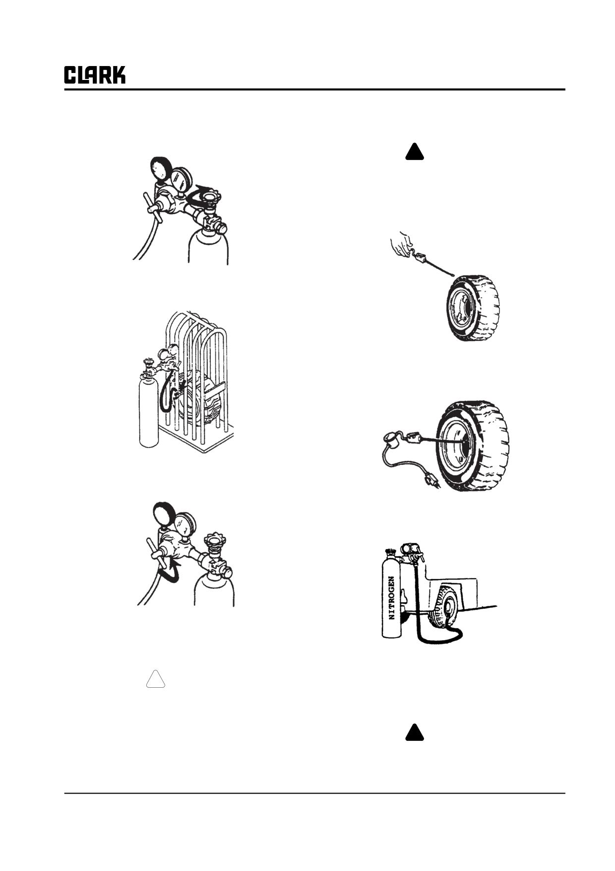
Group 22, Wheels and Tires
6. Turn the tank valve clockwise (CW) and close the
Checking and Adjusting Tire Pressure
valve.
!
WARNING
Before you add air pressure to the tire, make
sure the lock ring is correctly positioned in
the rim and wheel wedge. The lock ring can
separate from the rim with enough force to
cause injury or death.
7. Disconnect the air chuck from the valve stem.
1. Attach a clip-on air chuck to valve stem. Stand by the
side of the wheel and put the correct air pressure in
the tire.
8. Turn the regulator valve counterclockwise (CCW) to
the off position.
2. If your air supply does not have enough pressure to
fill the tire, you can use a nitrogen cylinder to get the
correct pressure.
9. Use a tire pressure gauge to check the tire pressure. If
necessary, put more air into the tire. Do this as many
times as necessary to reach the correct tire pressure.
3. Put a clip-on type air chuck on the nitrogen cylinder
! CAUTION
hose and attach it to the valve stem. Follow the pro-
cedures described previously for adjustment of the
Use a long-handled gauge so that your hand
nitrogen cylinder valves.
does not go inside the cage, or in front of any
component of a multi-piece wheel.
!
WARNING
Use nitrogne only. Do not use oxygen or any
other gas to fill tires.
SM 765, Nov ’06
Pneumatic Wheels and Tires • 22-2-9
NOTE :
Group 22, Wheels and Tires
SM 765, Nov ’06
GROUP 23
GROUP 23
BRAKE SYSTEM
Brake System Specifications and Description
Section 1
Service Brake Troubleshooting
Section 2
Brake Pedal Linkage & Adjustments
Section 3
Brake Bleeding
Section 4
Pedal and Master Cylinder Service
Section 5
Parking Brake Service
Section 6
SM 765, Dec ’06
Group 23, Brake system
NOTE :
Group 23, Brake system
SM 765, Dec ’06