Clark GEX20-30 (RATED CAPACITY : 2000~3000kg). SERVICE MANUAL (2006) - page 1
GEX20-30
SERVICE MANUAL
RATED CAPACITY : 2000~3000kg
Part No. 8051044
Book No. SM-765
Dec. 2006
#40-1,Ungnam-Dong,
changwon-city, Kyungnam,
Korea
Truck Models Covered by this Manual
This manual consists of “base” module that pertains
You may, however, purchase specific modules and
to all GEX20-30 models and other modules that per-
expand your manual to fully cover multiple models.
tain only to specific models. Manuals shipped with
To do so, order the desired modules as you would
the truck contain the base module and the modules
any other Clark part.
specific to the purchased truck.
Arrangement and Use of this Manual
Clark arranges parts and service procedures by stan-
You can quickly locate a specific point in the manual
dardized Groups. In this manual, Groups are similar
by using the headers and footers that appear on every
to “chapters”. Groups are listed in the indexes on the
Section page. The following illustration points out
next page.
these areas.
Each Group begins with a table of contents that
shows the Sections contained within the Group.
Lengthy Sections also begin with a table of contents.
Each Group and Section has an identifying name and
number, or “ID”.
Each page also has a unique ID. The page ID con-
sists of three numbers separated by hyphens. The
three numbers represent the Group number, the Sec-
tion number, and the page number. For example,
“00-1-2” on the lower corner of the page indicates
This manual is intended for the use of trained service
Group 00, Section 1, page 2.
personnel. Please read Group SA, “Safe Mainte-
nance”, and the Operator’s Manual before working
The Group number sometimes has a letter or letters
on or operating the truck.
added to it in parentheses if one or more variations of
the Group exist. For example, if the truck has a stan-
dard transaxle, Group 06 is expressed as “06(S)”; if
the truck has a hydrostatic transmission, Group 06 is
expressed as “06(H)”.
SM765, Nov ’06
NOTE :
,
SM765, Nov ’06
CONTENTS
Contents by Group and Section
(Alphabetical listing of contents appears on next page.)
Contents are listed here by Group number and name followed by Section number and name:
SA
SAFE MAINTENANCE
6. Parking Brake Service
1. Safety
25
STEERING COLUMN AND GEAR
2. Lifting, Jacking, and Blocking
3. Towing
1. Steering System Specifications and Description
2. Steering System Troubleshooting
3. Steering Column Removal and Installation
PS
PERIODIC SERVICE
4. Steering System Relief Pressure Check and
1. Maintenance Schedule
Adjustment
2. Planned Maintenance
5. Steering Gear Overhaul
3. The PM Inspection Form
26
STEERING AXLE
12
BATTERY
1.Steering Axle Specifications and Description
1. Battery Service
2. Steering Wheel Bearing Maintenance and Adjust-
ment
13
WIRING, SWITCHES, AND INSTRUMENTS
3. Steering Axle Removal and Installation
4. Steering Axle Overhaul
1. Schematic Electric Circuit Diagrams
5. Steering Cylinder Removal and Installation
2. General Electrical Service Tips
6. Steering Cylinder Overhaul
3. Wiring and Cables
7. Pivot-Turn Steering Axle Maintenance
4. Switches and Sensors
5. Instrument Panel
29
HYDRAULIC SUMP, FILTERS, AND PUMP
1. Main Hydraulic Sump, Filters, and Pump Specifi-
16
ELECTRIC MOTORS
cations and Description
1. Motor Specifications And Descriptions
2. Main Hydraulic Pump Troubleshooting
2. Drive Motors Overhaul
3. Main Hydraulic Removal and Installation
3. Pump Motor Overhaul
30
HYDRAULIC CONTROL VALVE/LIFT CIRCUIT
17
ELECTRICAL CONTACTORS
1. Hydraulic Control Valve/Lift Circuit Specifications
1. Contactors Specifications and Overhaul
and Description
2. Hydraulic Schematic
19
MOTOR CONTROLS
3. Hydraulic System Troubleshooting
1. Description
4. Hydraulic System Pressure Checks and Adjust-
2. Control Programming
ments
3. Control troubleshooting
5. Hydraulic Control Valve Removal and Replace-
4. GEX Factory Control Settings
ment
20
DRIVE AXLE
32
TILT CYLINDERS
1. Specification and description of drive axle
1. Tilt Cylinder Specifications and Description
2. Troubleshooting of wheel drive axle
2. Tilt Cylinder Checks and Adjustments
3. General operation of drive axle
3. Tilt Cylinder Removal and Replacement
4. Disassembly and Reassembly of drive axle
4. Tilt Cylinder Overhaul
5. Disassembly and Reassembly of axle end
6. Adjustment
34
UPRIGHTS
1. Upright Specifications and Description
22
WHEELS AND TIRES
2. Troubleshooting
1. Wheels & Tires Specifications and Description
3. Upright Inspection
2. Pneumatic Wheels and Tires
4. Carriage and Upright Roller Clearance Checks
and Shim Adjustments
23
BRAKE SYSTEM
5. Cylinder Removal, Shimming, Overhaul and
1. Brake System Specifications and Descriptions
Replacement
2. Service Brake Troubleshooting
6. Upright Chain Inspection, Adjustment, and
Replacement
3. Brake Pedal Linkage & Adjustments
7. Fork and Carriage Removal and Replacement
4. Brake Bleeding
8. Upright Removal and Replacement
5. Pedal and Master Cylinder Service
SM 765, Nov '06
CONTENTS -1
CONTENTS
38
COUNTERWEIGHT AND CHASSIS
1. Counterweight Specifications and Description
2. Counterweight Removal and Installation
3. Overhead Guard Removal and Installation
4. Floor Plate, Seat, and Seat Deck Removal and
Installation
40
SPECIFICATIONS
1. Nameplate and Decals
2. General Specifications
3. Hydraulic Fitting Tightening Procedure
CONTENTS -2
SM 765, Nov '06
CONTENTS
Alphabetical Listing of Topics
(Contents are listed by order of Group and Section numbers on previous page.)
Contents are listed here by topic followed by the Group#-Section# the topic appears in:
Battery Service
12-1
Main Hydraulic System Specifications and
Description
29-1
Brake Caliper Removal and Replacement
23-4
Maintenance Schedules
PS-1
Brake Overhaul
23-6
Motor Specifications And Descriptions
16-1
"Brake Pedal and Master Cylinder Removal, Replacement,
and Adjustment "
23-3
Nameplate and Decals
40-1
Brake Specifications
23-1
Overhead Guard Removal and Installation
38-3
"Brake System Fluid Check, Fill, and Bleed
"Parking Brake Removal, Replacement, and
Specifications and Description"
23-2
Adjustment"
23-5
Carriage and Upright Roller Clearance Checks and
Pivot-Turn Steering Axle Maintenance
26-7
Shim Adjustment
34-4
Planned Maintenance Program
PS-2
Checks and Adjustments
32-2
PM Inspection Form
PS-3
Contactors
17-1
Programming & Adjustments Using ZAPI Handset... 19-2
Control troubleshooting
19-3
Pump Motor Overhaul
16-3
Counterweight Removal and Installation
38-2
Safety
SA-1
Counterweight Specifications and Description
38-1
Schematic Electric Circuit Diagrams
13-1
"Cylinder Removal, Shimming, Overhaul and
Steering Axle Overhaul
26-4
Replacement"
34-5
Steering Axle Removal and Installation
26-3
Description
19-1
Steering Axle Specifications and Description
26-1
Drive Axle Fluid Check and Change
20-2
Steering Column Removal and Installation
25-3
Drive Axle Overhaul
20-5
Steering Cylinder Removal and Installation
26-5
Drive Axle Removal and Installation
20-4
Steering Cylinder Overhaul
26-6
Drive Axle Specifications and Description
20-1
Steering Gear Overhaul
25-5
Drive Axle Troubleshooting
20-3
Steering System Relief Pressure Check and Adjustment
25-4
Drive Motors Overhaul
16-2
Steering System Specifications and Description
25-1
"Floor Plate, Seat, and Seat Deck Removal and
Steering System Troubleshooting
25-2
Installation"
38-4
Steering Wheel Bearing Maintenance and Adjustment
26-2
Fluids and Filters
29-2
Switches and Sensors
13-4
Fork and Carriage Removal and Replacement
34-7
Tilt Cylinder Overhaul
32-4
General Electrical Service Tips
13-2
Tilt Cylinder Removal and Installation
32-3
General Specifications
40-2
Tilt Cylinder Specifications and Description
32-1
Hydraulic Fitting Tightening Procedure
40-3
TMX Factory Control Settings
19-4
Hydraulic System Pressure Checks and Adjustments29-4
Towing
SA-3
Hydraulic System Removal and Overhaul
29-5
Trouble shooting
34-2
Hydraulic System Schematic
30-1
"Upright Chain Inspection, Adjustment and
Hydraulic System Troubleshooting Troubleshooting.. 29-3
Replacement"
34-6
Hydraulic Control Valve/Lift Circuit Specifications and
Upright Inspection
34-3
Description
30-1
Upright Removal and Replacement
34-8
Hydraulic Control Valve Removal and Replacement
30-5
Upright Specifications and Description
34-1
Hydraulic Schematic
30-2
Wheels & Tires Mounting and Maintenance
22-2
Hydraulic System Pressure Checks and Adjustments
30-4
Wheels & Tires Specifications and Description
22-1
Hydraulic System Troubleshooting
30-3
Wiring and Cables
13-3
Instrument Panel
13-5
"Lifting, Jacking, and Blocking the Truck"
SA-2
Main Hydraulic Sump, Filters, and Pump
Specifications and Description
29-1
Main Hydraulic Pump Troubleshooting
29-2
Main Hydraulic Removal and Installation
29-3
SM 765, Nov '06
CONTENTS -3
NOTE :
Alphabetical Listing of Topics
SM 765, Dec '04
REVISION HISTORY
Nov. 2006
When new or revised information is published to update this
manual the action to be taken with the pages is indicated in
Mark
Indication
Action required
the table.
❍
Page to be newly added
Add
Pages not marked are not currently revised, but are
●
Page to be replaced
Replace
included for page numbering continuity.
(
)
Page to be deleted
Discard
Revision
Revision
Revision
Revision
Mark
Page
Mark
Page
Mark
Page
Mark
Page
number
number
number
number
SA-1-1
12-1-2
13-4-6
19-2-10
SA-1-2
12-1-3
13-5-1
19-2-11
SA-1-3
12-1-4
13-5-2
19-2-12
SA-1-4
12-1-5
13-5-3
19-2-13
SA-1-5
12-1-6
13-5-4
19-2-14
SA-2-1
19-2-15
SA-2-2
13-1-1
16-1-1
19-2-16
SA-2-3
13-1-2
16-1-2
19-2-17
SA-2-4
13-1-3
16-2-1
19-2-18
SA-2-5
13-2-1
16-2-2
19-2-19
SA-3-1
13-2-2
16-2-3
19-3-1
SA-3-2
13-2-3
16-3-1
19-3-2
SA-3-3
13-3-1
16-3-2
19-3-3
13-3-2
16-3-3
19-3-4
PS-1-1
13-3-3
19-3-5
PS-1-2
13-3-4
17-1-1
19-3-6
PS-1-3
13-3-5
17-1-2
19-3-7
PS-1-4
13-3-6
19-3-8
PS-1-5
13-3-7
19-1-1
19-3-9
PS-2-1
13-3-8
19-1-2
19-3-10
PS-2-2
13-3-9
19-1-3
19-3-11
PS-2-3
13-3-10
19-1-4
19-3-12
PS-2-4
13-3-11
19-1-5
19-3-13
PS-2-5
13-3-12
19-1-6
19-3-14
PS-2-6
13-3-13
19-1-7
19-3-15
PS-2-7
13-3-14
19-1-8
19-3-16
PS-2-8
13-3-15
19-1-9
19-3-17
PS-2-9
13-3-16
19-1-10
19-4-1
PS-2-10
13-3-17
19-2-1
19-4-2
PS-2-11
13-3-18
19-2-2
19-4-3
PS-2-12
13-3-19
19-2-3
19-4-4
PS-2-13
13-3-20
19-2-4
PS-2-14
13-4-1
19-2-5
20-1-1
PS-3-1
13-4-2
19-2-6
20-1-2
PS-3-2
13-4-3
19-2-7
20-2-1
13-4-4
19-2-8
20-3-1
12-1-1
13-4-5
19-2-9
20-3-2
SM 765, Nov ’06
REVISION HISTORY - 1
REVISION HISTORY
Revision
Revision
Revision
Revision
Mark
Page
Mark
Page
Mark
Page
Mark
Page
number
number
number
number
20-4-1
25-4-2
29-1-5
34-2-3
20-4-2
25-5-1
29-1-6
34-2-4
20-4-3
25-5-2
29-2-1
34-3-1
20-5-1
25-5-3
29-2-2
34-3-2
20-5-2
25-5-4
29-2-3
34-3-3
20-6-1
25-5-5
29-3-1
34-3-4
20-6-2
25-5-6
29-3-2
34-3-5
20-6-3
25-5-7
29-3-3
34-3-6
34-3-7
22-1-1
26-1-1
30-1-1
34-3-8
22-2-1
26-1-2
30-1-2
34-3-9
22-2-2
26-2-1
30-2-1
34-3-10
22-2-3
26-2-2
30-2-2
34-4-1
22-2-4
26-2-3
30-3-1
34-4-2
22-2-5
26-2-4
30-3-2
34-4-3
22-2-6
26-3-1
30-4-1
34-4-4
22-2-7
26-3-2
30-4-2
34-4-5
22-2-8
26-3-3
30-4-3
34-4-6
22-2-9
26-3-4
30-5-1
34-4-7
26-4-1
30-5-2
34-4-8
23-1-1
26-4-2
30-5-3
34-4-9
23-1-2
26-4-3
30-5-4
34-4-10
23-1-3
26-5-1
34-5-1
23-2-1
26-5-2
32-1-1
34-5-2
23-2-2
26-5-3
32-2-1
34-5-3
23-3-1
26-6-1
32-2-2
34-5-4
23-3-2
26-6-2
32-2-3
34-5-5
23-3-3
26-6-3
32-3-1
34-5-6
23-4-1
26-6-4
32-3-2
34-6-1
23-5-1
26-7-1
32-3-3
34-6-2
23-5-2
26-7-2
32-3-4
34-6-3
23-5-3
26-7-3
32-4-1
34-6-4
23-6-1
26-7-4
32-4-2
34-6-5
23-6-2
26-7-5
32-4-3
34-6-6
26-7-6
34-6-7
25-1-1
26-7-7
34-1-1
34-6-8
25-1-2
26-7-8
34-1-2
34-7-1
25-2-1
26-7-9
34-1-3
34-7-2
25-2-2
26-7-10
34-1-4
34-7-3
25-3-1
34-1-5
34-7-4
25-3-2
29-1-1
34-1-6
34-8-1
25-3-3
29-1-2
34-1-7
34-8-2
25-3-4
29-1-3
34-2-1
34-8-3
25-4-1
29-1-4
34-2-2
34-8-4
2 - REVISION HISTORY
SM 765, Nov ’06
REVISION HISTORY
Revision
Revision
Revision
Revision
Mark
Page
Mark
Page
Mark
Page
Mark
Page
number
number
number
number
38-1-1
38-1-2
38-2-1
38-2-2
38-2-3
38-3-1
38-3-2
38-4-1
38-4-2
38-4-3
40-1-1
40-1-2
40-1-3
40-1-4
40-1-5
40-1-6
40-2-1
40-2-2
40-2-3
40-2-4
40-3-1
SM 765, Nov ’06
REVISION HISTORY - 3
NOTE :
REVISION HISTORY
SM 765, Nov ’06
GROUP SA SAFE MAINTENANCE
GROUP SA
SAFE MAINTENANCE
Safety
Section 1
Lifting, Jacking, and Blocking the Truck
Section 2
Towing
Section 3
SM 765, Nov ’06
Group SA SAFE MAINTENANCE
NOTE :
Group SA SAFE MAINTENANCE
SM 765, Nov ’06
Group SA, Safe Maintenance
Section 1
Safety
Safety Signs and Messages
2
Safe Maintenance Practices
2
General Shop Precautions
4
SM 765, Nov ’06
Safety • SA-1-1
Group SA, Safe Maintenance
Safety Signs and Messages
Safe Maintenance Practices
Safety signs and messages in this manual and on the lift
The following instructions have been prepared from cur-
truck provide instructions and identify specific areas
rent industry and government safety standards applicble to
where potential hazards exist and special precautions
industry truck operation and maintenance. These recom-
should be taken. Be sure you know and understand the
mended procedures specify conditions, methods, and ac-
meaning of these instructions, signs, and messages. Dam-
cepted practices that aid in the safe maintenance of indus-
age to the truck, death, or serious injury to you or other
trial trucks. They are listed here for the reference and
persons may result if these messages are not followed.
safety of all workers during maintenance operations.
Carefully read and understand these instructions and
NOTE
the specific maintenance procedures before attempting
This message is used when special informa-
to do any repair work.
tion is required relating to procedures, equip-
ment, tools, pressures, capacities, and other
When in doubt of any maintenance procedure, please con-
special data.
tact your local Clark dealer.
1.
Powered industrial trucks can become hazardous if
IMPORTANT
maintenance is neglected. Therefore, suitable mainte-
This message is used when special precau-
nance facilities, trained personnel, and procedures
tions should be taken to ensure a correct
must be provided.
action or to avoid damage to, or malfunction
2.
Maintenance and inspection of all powered industrial
of, the truck or a component.
trucks shall be done in conformance with the manu-
facturer’s recommendations.
! CAUTION
3.
A scheduled planned maintenance, lubrication, and
This message is used as a reminder of safety
inspection program shall be followed.
hazards that can result in personal injury if
4.
Only trained and authorized personnel shall be per-
proper precautions are not taken.
mitted to maintain, repair, adjust, and inspect indus-
trial trucks. Work should be performed in accordance
with the manufacturer’s specifications.
! WARNING
This message is used when a hazard exists
5.
Properly ventilate work area, vent exhaust fumes,
that can result in injury or death if proper
and keep shop clean and floor dry.
precautions are not taken.
6.
Avoid fire hazards and have fire protection equip-
ment present in the work area. Do not use an open
flame to check for level or leakage of fuel, electro-
! DANGER
lyte, or coolant. Do not use open pans of fuel or flam-
This message is used when an extreme haz-
mable cleaning fluids for cleaning parts.
ard exists that can result in injury or death or
7.
Before starting work on truck:
serious injury if proper precautions are not
a. Wear eye protection and remove all jewelry.
taken.
b. Raise drive wheels off of floor or disconnect
power source. Use blocks or other positive truck
The above terms have been adopted by Clark Material
positioning devices
Handling Company. The same terms may be used in dif-
c. Disconnect battery before working on the electri-
ferent context in service literature supplied directly or
cal system.
indirectly by vendors or truck components.
8.
Before working on engine fuel system of gasoline or
diesel-powered trucks, be sure the fuel shut-off valve
is closed.
9.
Operation of the truck to check performance must be
conducted in an authorized, safe, clear area.
SA-1-2 • Safety
SM 765, Nov ’06
Group SA, Safe Maintenance
10.
Before starting to drive truck:
19. Modifications and additions that affect capacity and
a. Be in operating position.
safe truck operation must not be done without the
b. Be sure parking brake is engaged.
manufacturer’s prior written approval. Capacity, op-
c. Put direction control in neutral.
eration and maintenance instruction plates, tags, or
d. Start engine.
decals must be changed accordingly. This is an
e. Check functioning of direction and speed con-
OSHA requirement.
trols, steering, brakes, warning devices, and any
20. Care must be taken to assure that all replacement
load handling attachments.
parts, including tires, are interchangeable with the
11.
Before leaving truck
original parts and of a quality at least equal to that
a. Stop truck.
provided in the original equipment. Parts, including
b. Put directional control in neutral.
tires, are to be installed per the manufacturer’s proce-
c. Apply the parking brake.
dures. Always use genuine CLARK or CLARK
d. Turn key switch OFF.
approved parts.
e. Put blocks at the wheels if truck is on an incline.
21. Use special care when removing heavy components
12.
Brakes, steering mechanisms, control mechanisms,
from the truck, such as counterweight, seat deck,
warning devices, lights, governors, guards, safety de-
upright, etc. Be sure that lifting and handling equip-
vices, and frame members must be carefully and reg-
ment is of the correct capacity and in good condition.
ularly inspected and maintained in a safe operating
Also, this removal may upset stability of the truck.
condition.
The frame must always be safely blocked for major
component removal.
13.
Special trucks or devices designed and approved for
hazardous area operation must receive special atten-
tion to ensure that maintenance preserves the origi-
NOTE
nal, approved, safe-operating features.
Become familiar with additional operating
and maintenance safety instructions con-
14.
Fuel systems must be checked for leaks and condi-
tained in the following publications:
tion of parts. Extra special consideration must be
given in the case of a leak in the fuel system. Action
ASME B56.1 - Safety Standard for Low Life and High
must be taken to prevent the use of the truck until the
Lift Trucks. Published by: American Society of Mechani-
leak has been corrected.
cal Engineers, Three Park Avenue, New York, NY 10016.
15.
The truck manufacturer’s capacity, operation, and
NFPA 505 - Powered Industrial Trucks. Including Type,
maintenance instruction plates, tags, or decals must
Areas of Use, Maintenance and Operation. Available
be maintained in legible condition.
from: National Fire Protection Assoc., Inc., Batterymarch
16.
Batteries, motors, controllers, limit switches, protec-
Park, Quincy, MA 02269.
tive devices, electrical conductors, and connections
General Industrial Standards, OSHA 2206: OSHA Safety
must be inspected and maintained in conformance
and Health Standards (29 CFR 1910), Subpart N-Materi-
with good practices. Special attention must be paid to
als Handling and Storage, Section 1910.178 Powered
the condition of electrical insulation.
Industrial Trucks. For sale by: Superintendent of Docu-
17.
To avoid injury to personnel or damage to the equip-
ments, U.S. Government Printing Office, Washington, DC
ment, consult the manufacturer’s procedures in
20402.
replacing contacts on any battery connection.
18.
Industrial trucks must be kept in a clean condition to
minimize fire hazards and help in the detection of
loose or defective parts.
SM 765, Nov ’06
Safety • SA-1-3
Group SA, Safe Maintenance
General Shop Precautions
!
CAUTION
The following list contains general precautions that
DO NOT STEAM-CLEAN
should be followed when working on a lift truck.
Do not steam-clean a solid state controlled
• Always wear safety glasses for eye protection.
truck. Excessive moisture will interfere with
• Remove rings, watches, loose jewelry and open
proper operation of the solid state compo-
clothing before working on a vehicle to avoid seri-
nents.
ous injury.
Solid state controls should be cleaned at regular intervals.
• Do not smoke while working on a vehicle.
Blowing dirt off with an air (207 kPa [30 psi] max.) hose
• Put power key switch in the OFF position, unless
periodically will, for the most part, eliminate any serious
otherwise required by the procedure.
cleaning problems. For a more thorough cleaning, water
may be hosed over the control. A mild detergent may be
• Set the parking brake. Place chocks to the front and
applied, such as that used for washing dishes. The deter-
rear surfaces of the tires to provide further restraint
gent should be rinsed off, and the controls must be thor-
from inadvertent vehicle movement.
oughly air-dried before putting truck into service.
• Use safety stands or blocks whenever a procedure
requires you to be under the vehicle.
Periodic cleaning should preclude the need for using a
degreaser. However, if a degreaser is used, we recommend
• Service electric truck batteries in a well-ventilated
Clark #1801146 Degreaser, or the equivalent to MS-180
area to avoid the danger of lighting explosive
Freon TF Degreaser and Cleaner. Only approved solvents
gases.
should be used to clean solid state control components.
• Follow the Safety Instructions outlined in Group
12, Battery Handling.
!
CAUTION
• Always discharge the capacitors prior to working
on or around electrical components.
CHECK POLARITY
• Avoid contact with battery acid. The battery con-
Battery polarity must be correct or the truck
tains corrosive acid which can cause injury. Follow
will not operate.
the instructions outlined in Group 12 and those
instructions received with your battery and charger.
!
CAUTION
USE TRUCK BATTERY ONLY
Cautions
Do not use a motor generator unit such as
The following is a list of “CAUTIONS” connected with
“ready power” or a battery charger to move
the operation and maintenance of trucks equipped with
and/or check this truck as serious damage
solid state control panels.
may occur.
IMPORTANT
! CAUTION
SAFETY NOTICE
WELDING ON TRUCKS
Read and understand all Safety Precautions
1.Make sure the truck has no grounds.
and Warnings before performing repairs on
lift trucks.
2.Disconnect truck battery.
Appropriate service methods and proper repair procedures
3.Protect electrical wiring and components
are essential to the safe, reliable operation of industrial
from weld spatter with a shield.
trucks, as well as the personal safety of the individual
4.Ventilate battery or remove battery from
doing the work. This Service Manual provides general
truck.
directions for accomplishing service and repair work with
If the above is not followed, damage can
tested, effective techniques. Following them will help
result to wiring and electrical components
assure successful repair and reliable truck operation.
on a solid state control truck.
SA-1-4 • Safety
SM 765, Nov ’06
Group SA, Safe Maintenance
There are numerous variations in procedures, techniques,
Improper or careless techniques cause accidents. Don’t
tools and parts used for servicing industrial trucks, as well
take chances with incorrect or damaged equipment. Read
as in the skill of the person doing the work.
and understand the procedures for safe operation and
maintenance outlined in this manual.
This manual cannot possibly anticipate all such variations
and provide advice or precautions as to each. Accordingly,
Drive and work safely. Follow the safety signs and
anyone departing from the instructions provided in this
their messages displayed in the work area, on the
manual, through procedures used or choice of tools, mate-
truck, and in this manual.
rials, and parts may jeopardize his or her personal safety
and the safety of the vehicle user.
SM 765, Nov ’06
Safety • SA-1-5
NOTE :
Group SA, Safe Maintenance
SM 765, Nov ’06
Group SA, Safe Maintenance
Section 2
Lifting, Jacking, and Blocking
Raising Drive Wheels
2
Chaning the Upright in Raised Position
3
Raised Rear of Truck
3
Raised Entire Truck
4
Shipping Tie-Down Instructions
5
! WARNING
Lifting or jacking any large piece of equipment such as a fork truck presents obvious hazards.
It must be done with great care and forethought. Consult the truck weight information in
Group 40, Specifications, to ensure that your lifting equipment is of adequate capacity.
SM 765, Nov ’06
Lifting, Jacking, and Blocking • SA-2-1
Group SA, Safe Maintenance
5.
Block the truck under the frame behind the drive
! CAUTION
wheels with solid blocking.
To perform these service procedures, first:
6.
Turn key switch OFF.
• Park truck on a level surface.
7.
Check for safe clearance between drive wheels,
• Put the upright in a vertical position and lower the
block and floor.
carriage fully down.
8.
Check the stability of the truck. Be sure that the
• Return control handle to neutral and turn key
blocks are located securely under the frame before
switch OFF.
operating the drive motor or working on truck.
9.
Lower the drive wheels to the floor by reversing this
! WARNING
procedure.
Defective equipment can cause accidents:
• Turn key switch ON.
All tools and lifting equipment must be in
• Tilt upright fully back.
good condition, meet the load capacity
requirements and have OSHA labels when
• Turn key switch OFF.
required. Tools with defects can fail, causing
10.
Remove the blocks from under the frame and upright
severe injury or death.
rails.
Raising Drive Wheels
This procedure uses the upright as a lever to lift the drive
wheels off the floor and prevent accidents due to inadvert-
ent powering of the drive wheels.
1. Park the truck safely.
2. Turn key switch ON. Tilt the upright fully back.
3. Put a solid 100 x 100 mm (4 x 4 inch) hardwood
block under the front section of each upright rail. Put
a 3-6 mm (0.125-0.250 inch) steel plate on top of
each block.
4. Tilt the upright fully forward. This will raise the
drive wheels off the floor.
GENERIC ILLUSTRATION
SA-2-2 • Lifting, Jacking, and Blocking
SM 765, Nov '06
Group SA, Safe Maintenance
Chaining the Upright in Raised Position
Raising Rear of Truck
This procedure is used to safely provide clearance for
The truck may be raised at the rear by jacking and block-
access from the front of truck to components on or near
ing under the center of the frame member at either the
the drive axle.
front or rear steer axle mounting, or under the center sec-
tion of the steer axle.
1. Park truck safely.
Refer to truck data plate for truck weights.
2. Put blocks at front of and rear of drive wheels.
3. Raise upright carriage.
!
WARNING
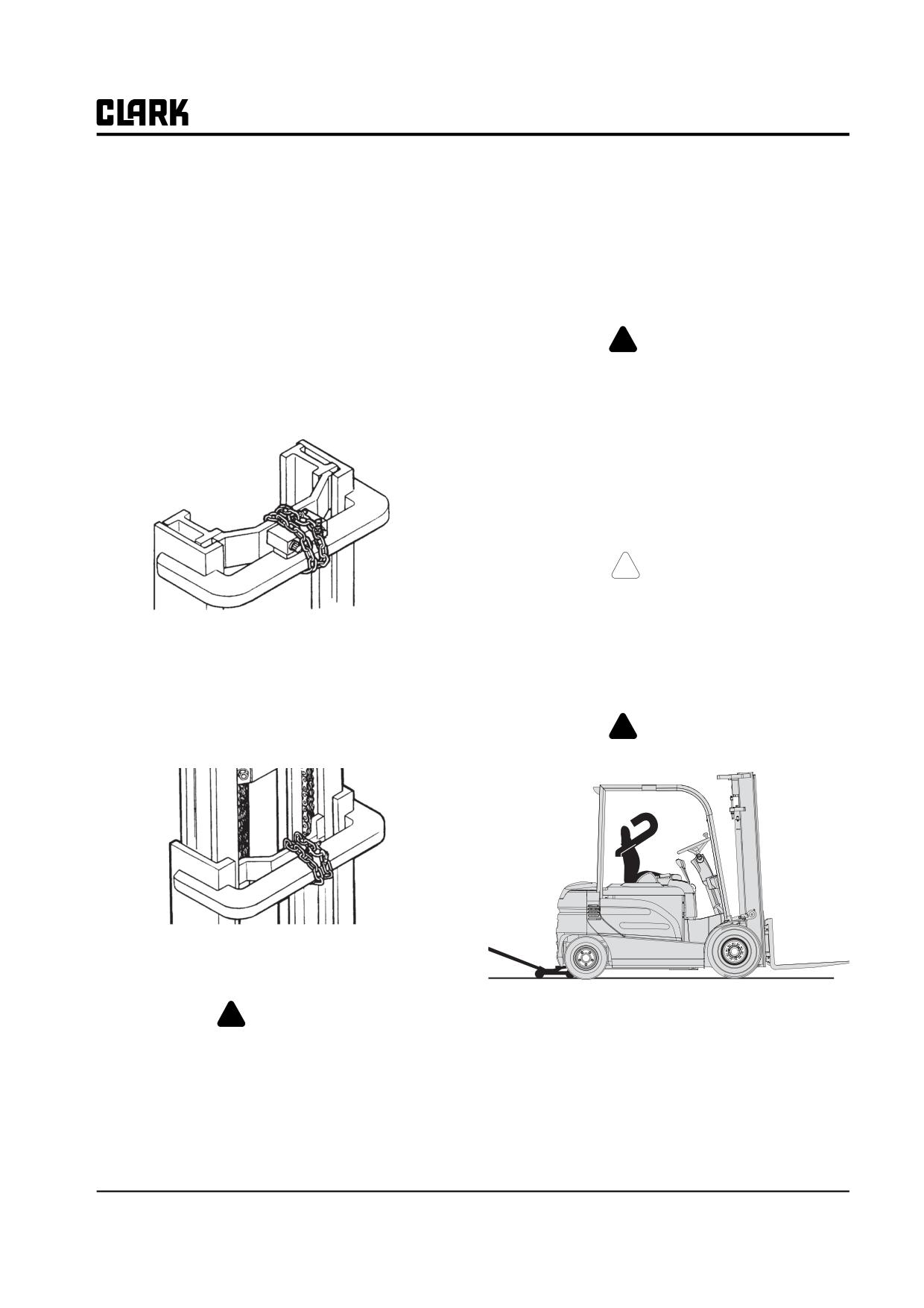
4. Chain the center inner rail tie bar to the top outer rail
An incorrectly installed counterweight can
tie bar as shown.
move or fall unexpectedly. NEVER LIFT OR
BLOCK A TRUCK USING THE COUN-
TERWEIGHT. Failure to follow procedures
outlined in this manual can result in injury or
death.
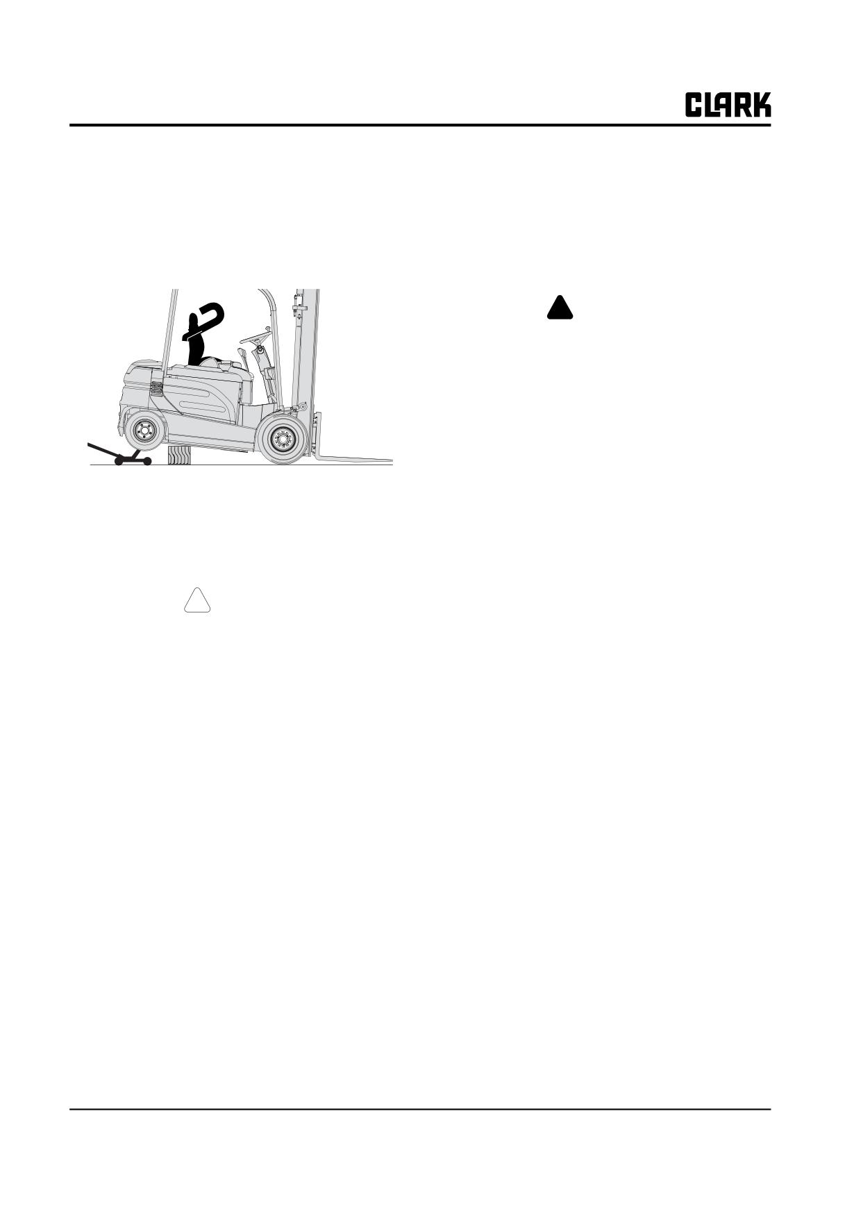
1. Park truck safely.
2. Put blocks at front and rear of drive wheels.
!
CAUTION
If possible, remove the battery from truck to
reduce weight for added safety and ease of
jacking.
Triple Stage Uprights: Chain the center intermediate rail
3. Put a floor jack under the steer axle mounting frame
tie bar and the lower inner rail tie bar to the top outer rail
member, centered between the two wheels.
tie bar.
!
WARNING
Never lift the truck by the counterweight.
5. Reverse the procedure to remove the chains.
! WARNING
If there is insufficient clearance under frame for your
jack, the truck may first be driven onto shims, such as
Keep hands, tools, etc. out of upright.
25x150x300 mm(1 x 6 x 12 in.) pieces of board, to
increase the truck frame underclearnce.
SM 765, Nov ’06
Lifting, Jacking, and Blocking • SA-2-3
Group SA, Safe Maintenance
4.
Raise the truck only as high as necessary to perform
Raising Entire Truck
the maintenance work.
Refer to truck data plate for truck weights.
5.
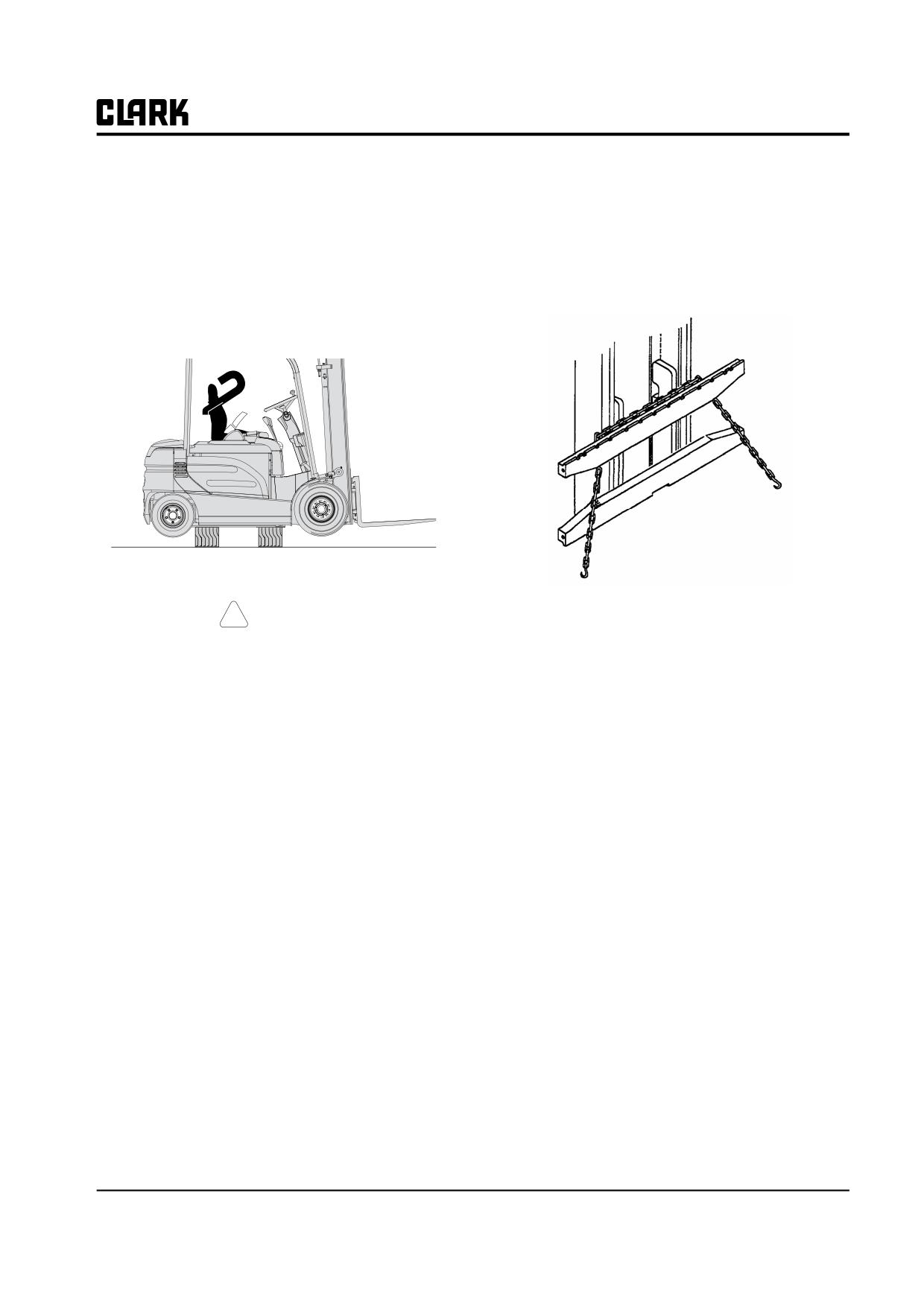
Put blocks at both sides of the truck, fully under the
frame main side structure. Put the blocks in front of
1.
Park truck safely. Lower upright fully.
but close to the counterweight and steer wheels for
2.
If necessary, drive truck onto boards to increase
best truck stability.
underclearance.
!
WARNING
SIDE-TO-SIDE TIPOVER. When jacking
side of truck, be sure upright is lowered fully.
Do not raise one side of the truck more than
about 50 mm (2 in.) higher than the other, to
avoid tipping truck over laterally.
END-TO-END TIPOVER. If the upright and
drive axle are removed while the truck is
blocked up, the truck will tip backward due
to the heavy counterweight. Upright and
counterweight must both be removed before
Put an equal number of blocks under each side of the
attempting to raise the truck for drive axle
truck to provide a level working position.
removal. The back of the truck must be sup-
6.
Lower the truck onto the blocks and remove the jack.
ported by blocking under the steer axle to
prevent movement.
! CAUTION
If the counterweight is removed while the
truck is up on blocks, the weight of the
Before performing any maintenance work,
upright and drive axle will cause the truck to
check the truck for stable condition on the
fall forward.
blocking by determining that it will not rock
on blocks.
3.
Put the jack under side frame, near the center of the
truck.
7.
When maintenance work is completed, lower the rear
IMPORTANT
of truck to the floor by reversing the above procedure
and lowering each side of the truck 50 mm (2 in.) at a
Be sure to put the jack squarely and fully
time:
under the main side structure of the frame.
• Put jack under frame and raise truck.
4.
Carefully raise the truck one side at a time, only as
• Carefully remove blocks and lower truck.
high as necessary to do the maintenance work, and
• Remove jack and blocks from drive wheels.
not more than 150 mm (6 in.) total.
SA-2-4 • Lifting, Jacking, and Blocking
SM 765, Nov '06
Group SA, Safe Maintenance
5. Put blocks under the side frame, at each side of the
Shipping Tie-Down Instructions
jack. Spread the blocks close to the steer and drive
wheels for maximum stability.
1. Front of Truck
a. With Upright and Carriage Installed
6. If using one jack, lower the truck onto the blocks and
• Lower the carriage fully.
move the jack to the opposite side. Repeat the lifting
procedure.
• Put a tie-down (e.g., chain) between the car-
riage fork bars.
7. Put the same size blocks under each side of the truck
so it will be leveled.
! CAUTION
b. Without Upright and Carriage Installed
Before performing any maintenance work,
• Put a chain across the truck floor plate. Protect
check the truck for stable condition on the
truck from chain damage by using covered
blocking.
chain or protective material under the chain at
contact points.
8. When maintenance work is completed, lower the
2. Rear of Truck
entire truck to the floor by reversing this procedure.
• Attach the tie-down to the toe-pin in bottom of
Lower the truck one side at a time, while carefully
counterweight.
removing the blocks. Be sure no tools or equipment
are under the truck or wheels.
NOTE
Depending on jack height, shims under the
tires may be needed for clearance to allow
removal of jack.
SM 765, Nov ’06
Lifting, Jacking, and Blocking • SA-2-5
NOTE :
Group SA, Safe Maintenance
SM 765, Nov ’06
Group SA, Safe Maintenance
Section 3
Towing
SM 765, Nov ’06
Towing • SA-3-1
Group SA, Safe Maintenance
If your truck is disabled but can be moved freely on its
4. Check that the counterweight bolts on both trucks are
own wheels without further damage, use the following
in place and properly torqued to 340-380 Nom (250-
procedures to tow the truck safely to a repair area.
280 ft-lb). These bolts are made of special, high-ten-
sile steel and are not commercially available. When
necessary, replace these bolt only with genuine Clark
! WARNING
replacement parts.
For your safety and the care of your truck,
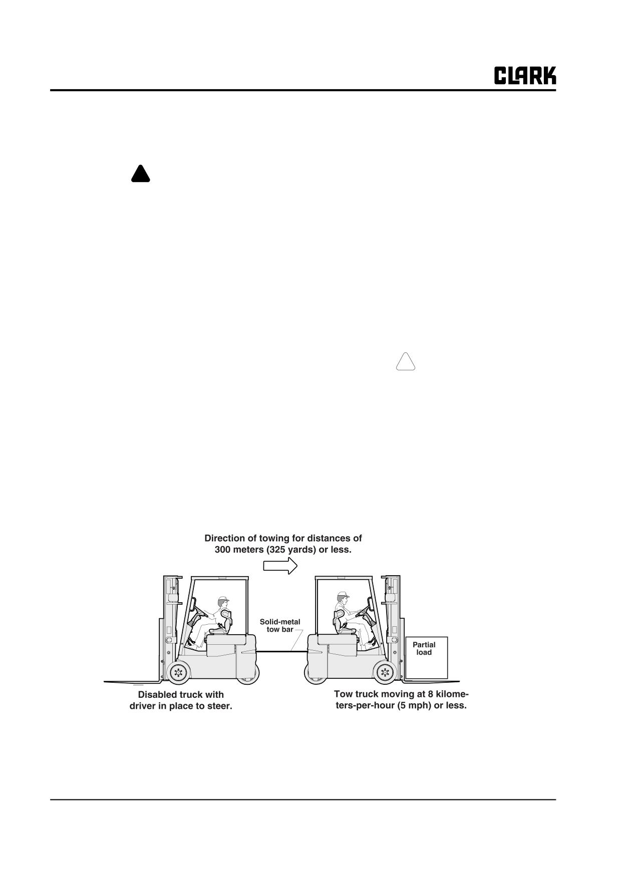
5. Use an approved, solid metal tow bar with towing couplers
use the proper equipment and carefully fol-
that connect to the towing pins in the counterweights of
low these recommendations for safe towing.
each truck.
Do not tow a lift truck if there is a problem
NOTE
with the brakes or tires, or if the steering
DOT-approved towing equipment is available from
cannot be operated.
your Clark dealer.
Do not tow up or down ramps or steep
6. Release the parking brake on the towed vehicle.
inclines.
Place directional control lever in NEUTRAL.
7. Tow the disabled truck backward. An operator must
Do not tow the disabled truck if traction or
be on the disabled truck.
weather conditions are poor.
!
CAUTION
1. Apply the parking brake or block the drive wheels on
the disabled truck while working around it.
The power steering will not operate on the
disabled truck when the power steering
2. When possible, raise the forks on the disabled truck
motor is not running. The steering hand-
300 mm (12 in) from the floor or ground. Secure the
wheel will be difficult to turn.
carriage on the upright with a chain.
3. Use a truck for towing that is of equal or larger
8. Tow the truck slowly. Careful towing is necessary to
capacity than the disabled truck. Carry a partial load
prevent injury to personnel or damage to the disabled
on the towing truck for improved traction
truck. The truck should be towed at a speed of less
than 8 kph (5 mph, or a moderate walking speed)
with a driver in place and steering the disabled truck.
SA-3-2 • Towing
SM 765, Nov '06
Group SA, Safe Maintenance
IMPORTANT
!
WARNING
Do not lift the disabled truck or any wheels
off the floor while the truck is being towed.
Always engage the parking brake when park-
ing a lift truck. The truck can roll and cause
9. Park the disabled truck in authorized areas only.
injury or death to personnel near it.
Fully lower the forks to the floor. Leave the direc-
tional control in neutral. Turn the key switch to OFF,
and engage the parking brake. Remove the key. Dis-
connect the battery. When necessary, block the
wheels to prevent the truck from rolling.
SM 765, Nov ’06
Towing • SA-3-3
NOTE :
Group SA, Safe Maintenance
SM 765, Nov ’06
GROUP PS PERIODIC SERVICE
GROUP PS
PERIODIC SERVICE
Maintenance Schedule
Section 1
Planned Maintenance Program
Section 2
The PM Inspection Form
Section 3
SM 765, Nov ’06
Group PS PERIODIC SERVICE
NOTE :
Group PS PERIODIC SERVICE
SM 765, Nov ’06
Group PS, Periodic Service
Section 1.
Maintenance Schedule
“Periodic Service” and “Planned Maintenance”
2
Determining Maintenance Intervals
2
GEX Service Chart/Lubrication Points
3
Recommended Periodic Service Schedule
4
SM 765, Nov ’06
Maintenance Schedule • PS-1-1
Group PS, Periodic Service
“Periodic Service” and “Planned
Determining Maintenance Intervals
Maintenance”
Time intervals on the charts on the next four pages and
elsewhere in this manual relate to truck operating hours as
The term “periodic service” includes all maintenance
recorded on the hourmeter, and are based on experience
tasks that should be performed on a regularly scheduled
Clark has found to be convenient and suitable under nor-
basis.
mal operation. Standard operating condition classifica-
tions are:
The term “Planned Maintenance” indicates a formalized
program of basic inspections, adjustments, and lubrica-
Normal Operation: Eight-hour material handling, mostly
tions that the Clark service organization provides custom-
in buildings or in clean, open air on clean, paved surfaces.
ers at a prescribed interval, usually 50-250 hours. The
recommended basic “Planned Maintenance” procedure is
Severe Operation: Prolonged operating hours or constant
given in Section 2 of this Group.
usage.
The current Section,”Maintenance Schedules,” specifies
Extreme Operation:
all maintenance tasks.including Planned Maintenance
• In sandy or dusty locations, such as cement plants,
tasks.that should be performed periodically, and suggests
lumber mills, and coal dust or stone crushing sites.
intervals at which they should be performed.
• High-temperature locations, such as steel mills and
foundries.
• Sudden temperature changes, such as constant trips
from buildings into the open air, or in refrigeration
plants.
If the lift truck is used in severe or extreme operating con-
ditions, the maintenance intervals should be shortened
accordingly.
IMPORTANT
MAINTENANCE INTERVALS. If the lift
truck is used in severe or extreme operating
conditions, the maintenance intervals should
be shortened ace. Put upright in vertical posi-
tion and fully lower the forks or attachment.
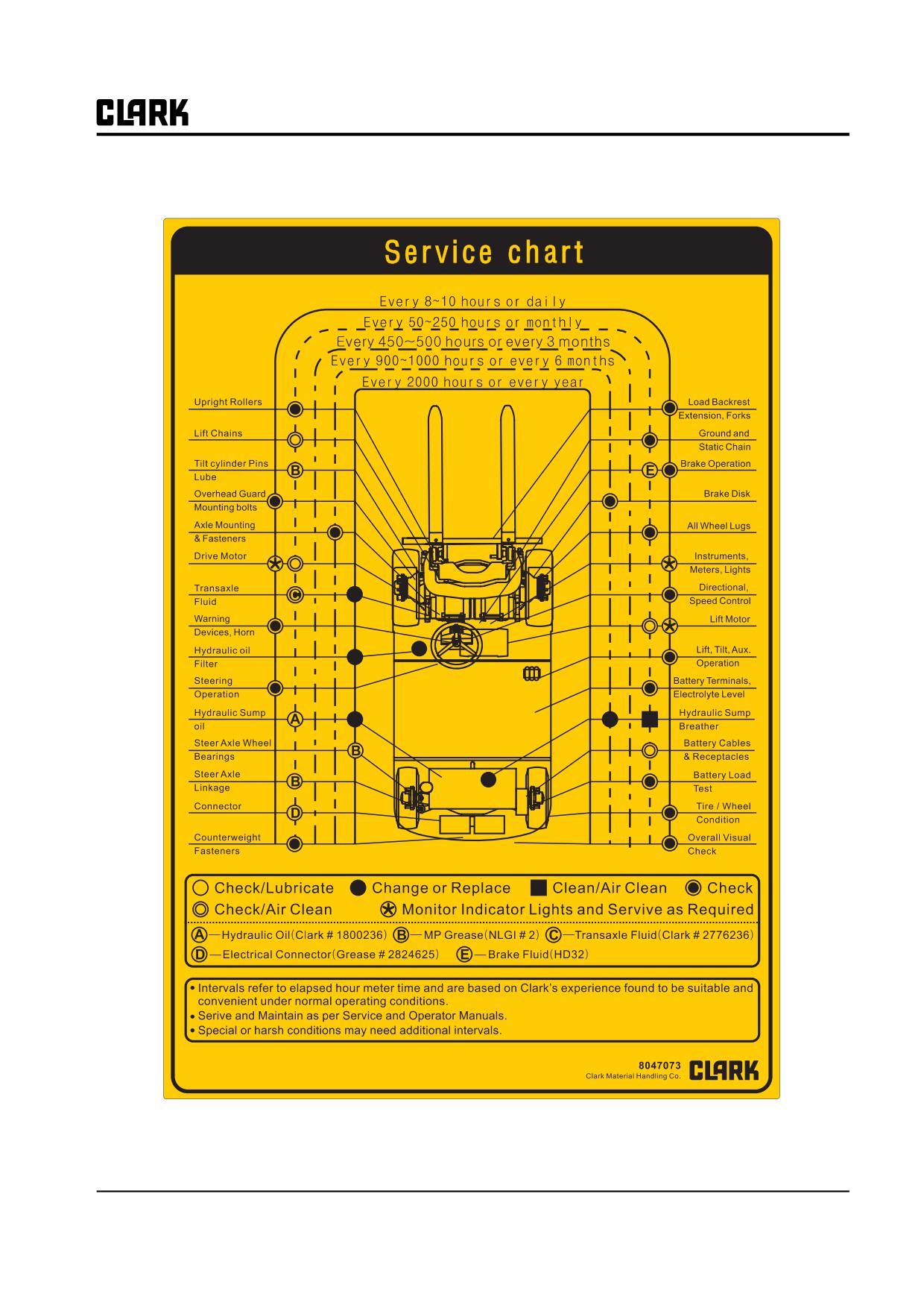
Service Chart/Lubrication Points
A decal, similar to the illustration below, is located on the
underside of the seat deck. This decal is a basic guide to
periodic
maintenance intervals and tasks. A more detailed chart is
supplied on the next page.
PS-1-2 • Maintenance Schedule
SM 765, Nov ’06
Group PS, Periodic Service
GEX Service Chart/Lubrication Points
SM 765, Nov ’06
Maintenance Schedule • PS-1-3
Group PS, Periodic Service
Recommended Periodic Service Schedule
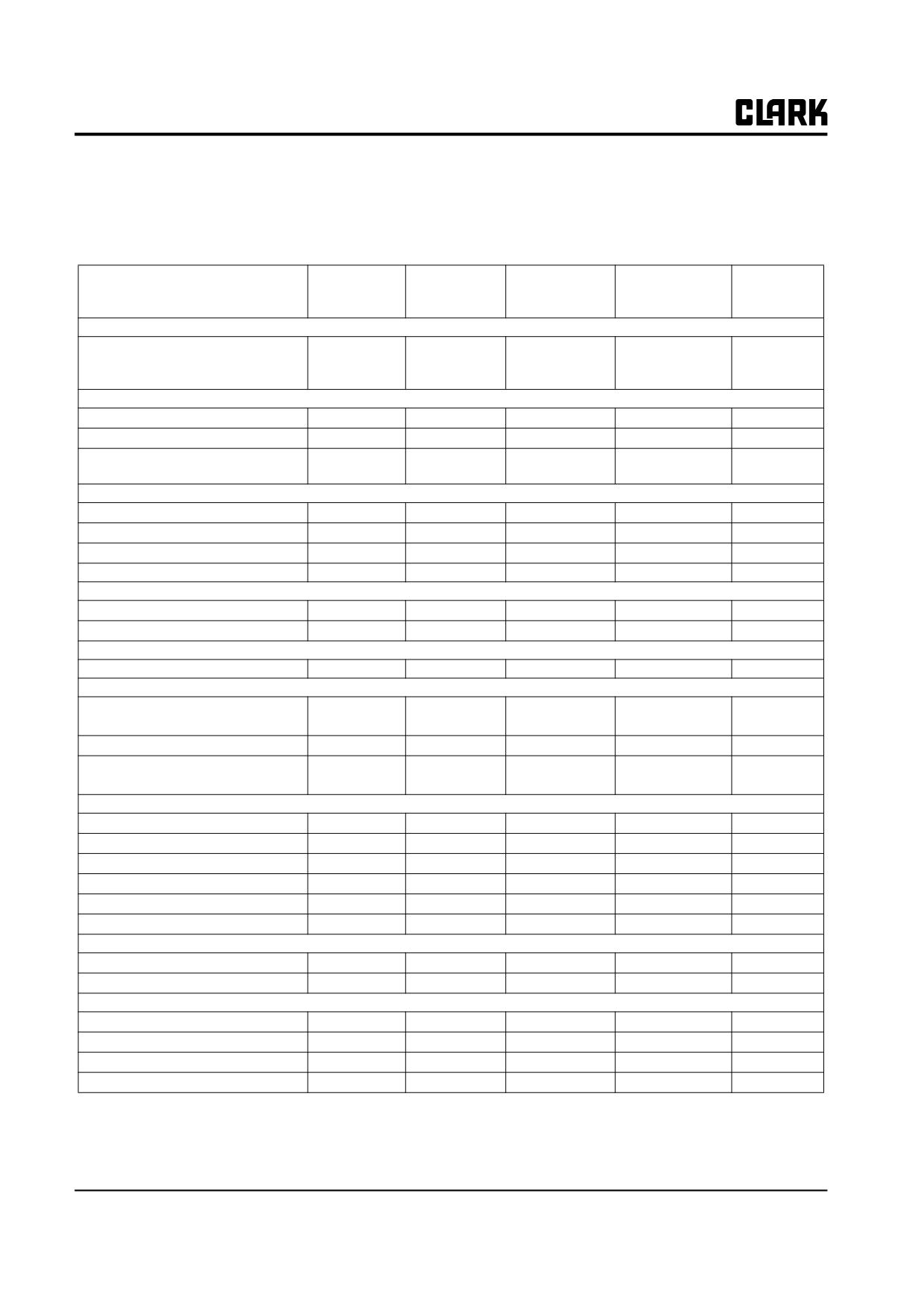
This chart lists maintenance tasks that should be done periodically, the suggested time intervals, and the service manual
Group in which the task is covered. Refer to Operator’s Manual for Daily Checks.
Every
Every
Every
Every
450- 500 Hours
900- 1000 Hours
2000 Hours
TASKS
1st 50 Hours
50-250 Hours
(or 3 months)
(or 6 months)
(or 1 year)
Group PS - Periodic Maintenance
Perform Planned Maintenance
inspections, lubrications, and adjust-
ments
Group 12 - Battery
Battery electrolyte level - check/add
Battery load voltage test
Battery terminals/cables - clean/
tighten
Group 13 Wiring and Instruments
Hourmeter - check
Lamp check - at start-up
Wiring harness - inspect
Instruments/accessories
Group 16 - Electric Motors
Drive motor - check/air clean
Lift pump motor - check/air clean
Group 17 -Contactors
Contactor tips - check/air clean
Group 19 - Motor Controls
Display - check display for error
codes
Controller - air clean
Controller connectors - check
and lubricate
Group 20 - Drive Axle
Air vent - inspect, clean or replace
Axle mounting bolts - inspect/tighten
.Pressure checks
Fluid change - drain/fill
Fluid filter - replace
Fluid level/condition - check/sample
Group 22 - Wheels And Tires
Wheel mounting bolts - tighten
Tire pressure/condition - check
Group 23 - Brakes
Operation - check
Service brake - check wear
Brake lines - check
Parking brake - check/adjust
PS-1-4 • Maintenance Schedule
SM 765, Nov ’06
Group PS, Periodic Service
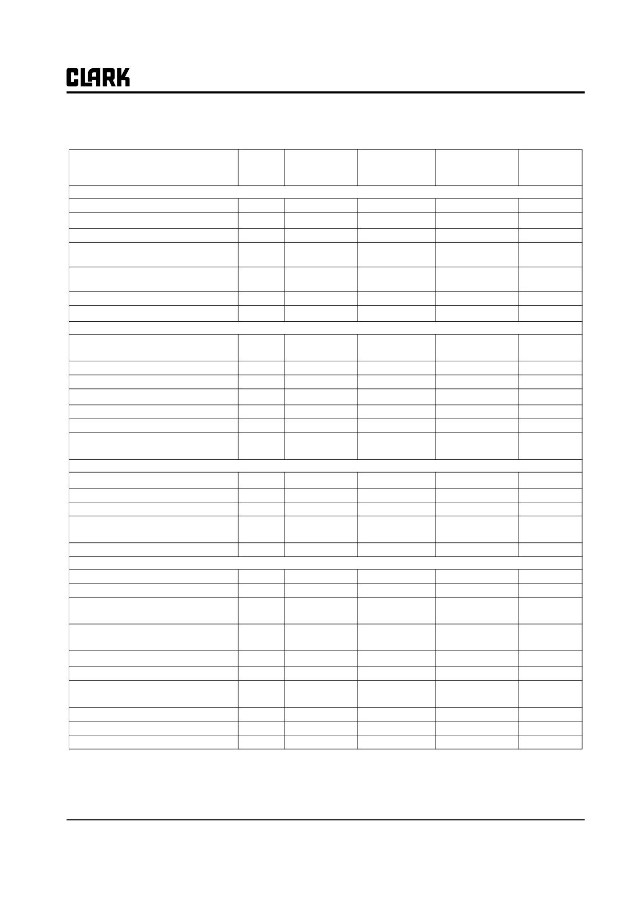
TASKS
Every
Every
Every
1st 50
Every
450- 500 Hours
900- 1000 Hours
2000 Hours
Hours
50-250 Hours
(or 3 months)
(or 6 months)
(or 1 year)
Group 25/26 - Steer Axle and Lines
Operation - check
Power steering relief pressure - check
Steer axle mounting - inspect
Steer wheel and trunnion bearings -
check
Steer wheel and trunnion bearings -
lubricate/adjust
Steering cylinder seals - check leakage
Steering linkage - lubricate
Group 29/30 - Hydraulic Lift System
Hydraulic fluid level/condition -
check/sample
Hydraulic fluid change - drain/fill
Hydraulic filler screen - clean
Hydraulic fluid filter - replace
Hydraulic tank breather - clean/replace
Control valve linkage - check/clean
Hydraulic system relief pressure - test/
adjust
Group 32 - Tllt Cylinders
Tilt cylinder adjustment - check/adjust
Tilt cylinder drift - test
Tilt cylinder mounting - check/tighten
Tilt cylinder rod ends - check/tighten/
lubricate
Tilt cylinder rod/seals - check for leaks
Group 34 - Upright, Lift Cylinders, Carriage, Forks
Operation - check
Carriage and lift chain - lubricate
Carriage chain condition - inspect/
adjust
Forks, latches, stop pin - inspect/check
wear
Lift chain condition - inspect/adjust
Load backrest
Upright cylinder/mounting - inspect/
tighten
Upright lift cylinder downdrift - test
Upright rollers - check
Upright trunnion bolts - tighten
SM 765, Nov ’06
Maintenance Schedule • PS-1-5
NOTE :
Group PS, Periodic Service
SM 765, Nov ’06
Group PS, Periodic Service
Section 2
Planned Maintenance
Use PM Report Form
2
How to Perform the PM Periodic Inspections and Maintenance
2
Visual Inspection
2
Operational Checks
5
Test Drive Truck with Load
6
Lift Mechanism and Controls
8
Battery Compartment Inspection
10
Motor Transistor Controls Inspection
10
Hydraulic Compartment Inspection
10
Cleaning
11
Air-Cleaning
12
Critical Fastener Torque Checks
12
Lubrication, Fluids, and Filters
12
Hydraulic Sump
12
Hydraulic Fluid and Filter Change
12
Sump Tank Breather Maintenance
13
Access to the Drive Axle
13
Drive Axle Fluid
13
Drive Axle Fluid Change
13
Truck Chassis Inspection and Lubrication
13
Upright and Tilt Cylinder Lubrication
13
Lift Chains
13
Air-Cleaning Motors
14
SM 765, Nov ’06
Planned Maintenance • PS-2-1
Group PS, Periodic Service
Use PM Report Form
A planned maintenance program of regular, routine
inspections and lubrication is important for long life and
troublefree operation of your lift truck. Make and keep
records of your inspections. Use these records to help
establish the correct PM intervals for your application and
to indicate maintenance required to prevent major prob-
lems from occurring during operation.
As an aid in performing and documenting your PM
inspections, Clark has prepared an Electric Truck Planned
Maintenance Report form. Copies of this form may be
obtained from your authorized Clark dealer. We recom-
mend that you use this form as a checklist, to make a
record of your inspection and truck condition.
Be sure all capacity, safety, and warning plates or decals
are attached and legible.
The periodic maintenance procedures outlined in this
manual are intended to be used with the PM report form.
They are arranged in groupings of maintenance work that
!
CAUTION
are done in a logical and efficient sequence.
Do not operate a lift truck with damaged or
missing decals and nameplates. Replace them
A check mark or entry is made on the PM Report Form
immediately. They contain important infor-
when the PM is performed. Please note the special coding
mation.
system for indicating the importance of needed repairs
and/or adjustments.
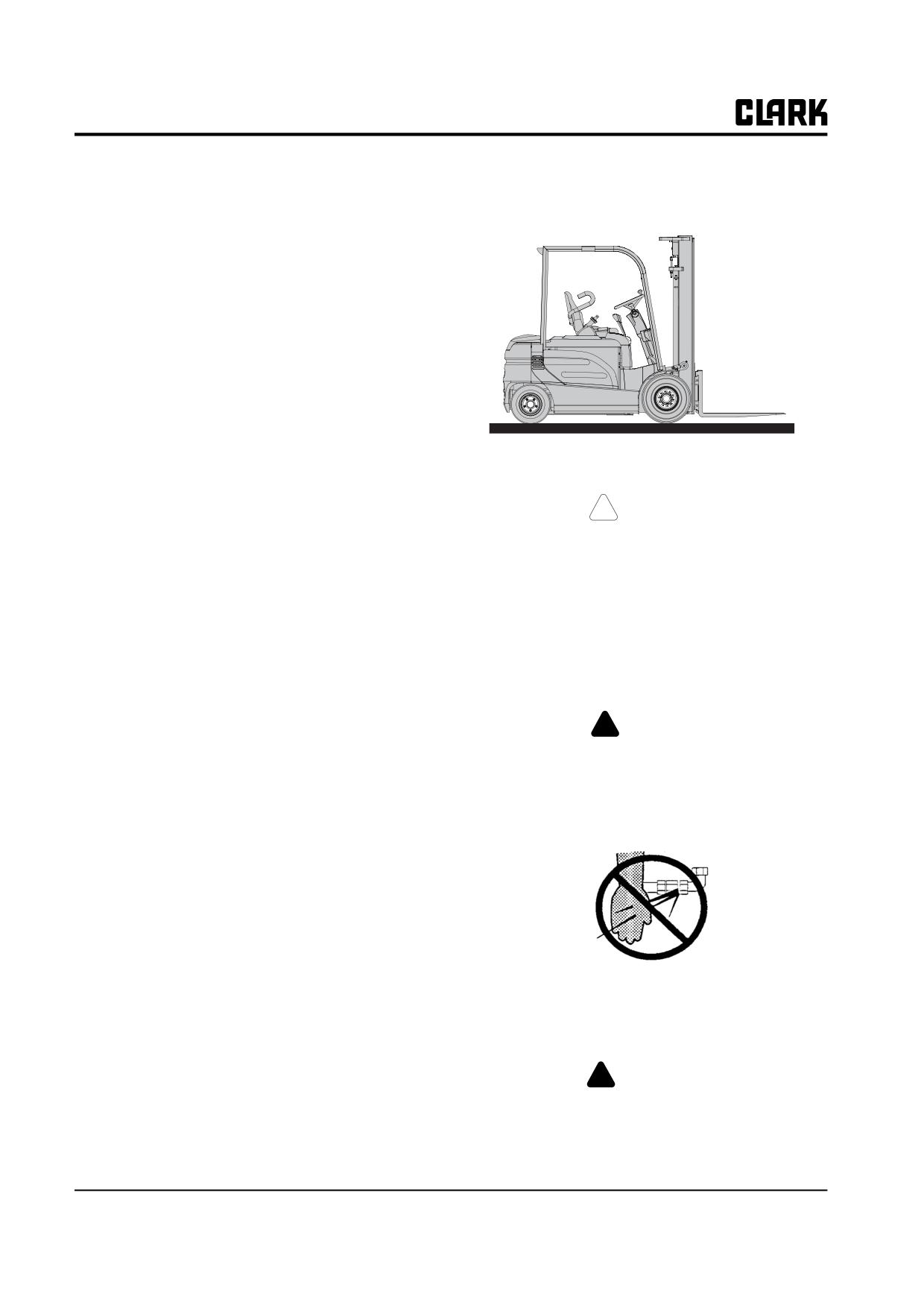
Inspect the truck for signs of external leakage of transmis-
When you have finished the PM inspections, be sure to
sion fluid, etc. Check for hydraulic leaks and loose fit-
give a copy of the report to the designated authority or the
tings. DO NOT use bare hands to check. Hydraulic Fluid
person responsible for lift truck maintenance.
may be hot or under pressure.
Do not make repairs or adjustments unless authorized to
do so.
!
DANGER
HYDRAULIC FLUID PRESSURE: Do not
For safety:
use your hands to check for hydraulic leak-
• Remove all jewelry (watch, rings, bracelets, etc.)
age. Fluid under pressure can penetrate your
before working on the truck.
skin and cause serious injury.
• Disconnect battery from truck receptacle before
working on electrical components.
• Wear safety glasses. Wear a safety (hard) hat in
industrial plants and in special work areas where
protection is necessary or required.
How to Perform the PM Periodic
Inspections and Maintenance
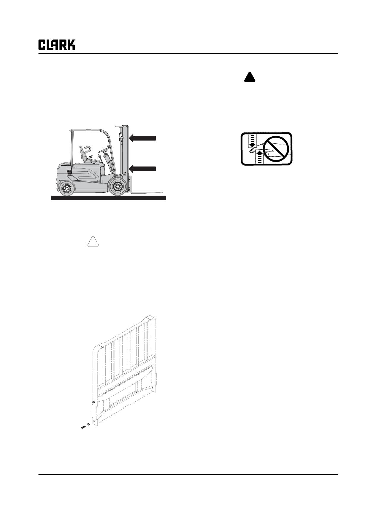
Be sure that the driver’s overhead guard, load backrest
extension, finger guards, and any other safety devices are
Visual Inspection
in place, undamaged, and attached securely.
Perform a visual inspection of the lift truck and its compo-
nents. Walk around the truck and take note of any obvious
!
WARNING
damage and maintenance problems. Check for loose fas-
For trucks equipped with spark-enclosed
teners and fittings.
(EE) construction, or with polyurethane
PS-2-2 • Planned Maintenance
SM 765, Nov ’06
Group PS, Periodic Service
tires, check the ground strap or chain for
!
DANGER
wear and secure attachment.
Uprights can drop suddenly if not properly
Check all of the critical components that handle or carry
blocked. Look at the upright, but keep hands,
the load.
tools, etc. out.
IMPORTANT
Uprights and lift chains require special atten-
tion and maintenance to maintain them in
safe operating condition. Refer to Lift Chain
Check the overhead guard for damage. Be sure that it is
Maintenance in Group 34 for additional
properly positioned and all mounting fasteners are in
information.
place and tight.
Check the upright assembly. Inspect the upright rails, car-
! CAUTION
riage rollers, lift chains, lift and tilt cylinders. Look for
obvious wear and damaged or missing parts. Check for
If load backrest has been removed, a bolt and
any loose parts or fittings. Check for leaks, damaged or
washer must be in place on each end of the
loose rollers, and rail wear (metal flaking). Carefully
top fork bar to act as a fork stop.
check the lift chains for wear, rust and corrosion, cracked
or broken links, stretching, etc. Check that the lift and car-
Check the load backrest for damage. Inspect the welds on
riage chains are correctly adjusted to have equal tension.
the carriage and load backrest for cracks. Be sure that the
Check that the lift chain anchor fasteners and locking
mounting fasteners are all in place and tight.
means are in place and tight.
Be sure all safety guards and chain retainers are in place
and not damaged. Inspect the carriage stops and cylinder
retainer bolts. Check all welded connections.
Inspect all lift line hydraulic connections for leaks. Check
the lift cylinder rods for wear nicks, grooves, and
scratches. Check the cylinder seals for leaks. Refer to
Group 34 for details on uprights.
SM 765, Nov ’06
Planned Maintenance • PS-2-3
Group PS, Periodic Service
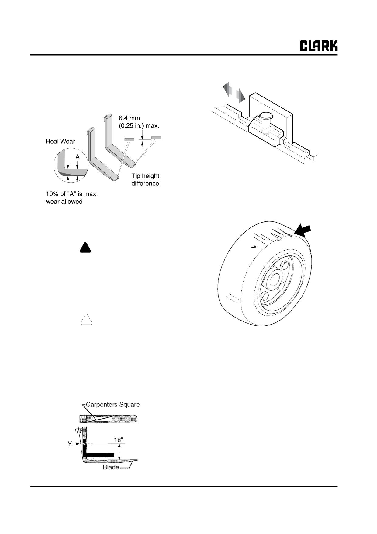
Forks
Inspect the load forks for cracks, breaks, bending and
wear. The fork top surfaces should be level and even with
each other. The height difference between both fork tips
should be no more than 6 mm (0.25 in.)
Inspect the fork latches. Be sure they are not damaged or
broken, operate freely and lock correctly. Check the fork
stop pins (or bolt and washer) for secure condition.
Wheels and Tires
NOTE
Your Clark dealer has special tools for mea-
suring fork wear.
! WARNING
If the fork blade at the heel is worn down by
more than l0%, the load capacity is reduced
and the fork must be replaced. DO NOT
attempt to fill with weld. See Group 34 for
inspection procedure.
Check the amount of wear at the heel of the fork.
! CAUTION
If the forks are obviously bent or damaged,
have them inspected by a trained mainte-
Check the condition of the drive and steer wheels and
nance person before operating the truck.
tires. Remove objects embedded in the tread. Inspect the
Inspect the forks for twists and bends. To check, put a 2 x
tires for excessive wear, break, “chunking out,” and bond
4 x 24 in. long block on the blade of the fork with the 4 in.
failure between the tire and rim.
surface against the blade. Put a 24 in. carpenter’s square
on the top of the block and against the shank. Check the
fork 18 in. above the blade to be sure it is not bent more
than 14.5 mm (0.6 in.) at Y.
PS-2-4 • Planned Maintenance
SM 765, Nov ’06
Group PS, Periodic Service
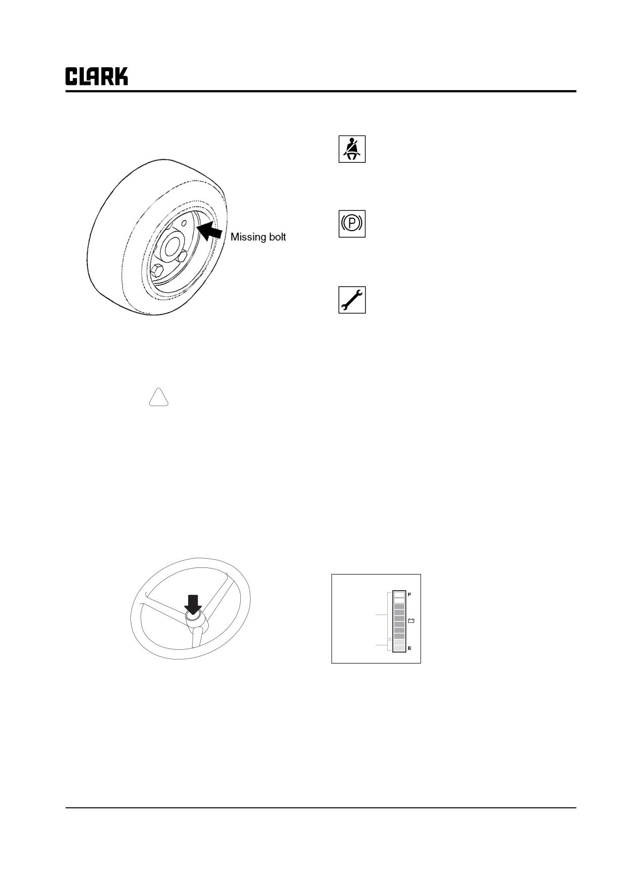
2. Using the Display
Seat Belt: At start up this symbol displays
along with an audio alarm for 4 seconds. This
display reminds you to fasten your seat belt.
Parking Brake: The symbol is displayed and "-
255" status code appears on the numeric dis-
play when parking brake is applied. Release
parking brake to operate truck.
Service Status: The following 5 codes are usu-
ally operator fault codes, and can be corrected
by as explained in "Section 5, Operating Proce-
dures." If you see any other codes displayed,
the truck needs to be serviced.
Check all wheel mounting bolts to be sure none are loose
•
-01 Seat Switch Open
or missing.
•
-061, -065 ,-140, -203, -207 Overheat of motor
and controller (Restart after cooling
! CAUTION
down)
Personnel working on wheels and tires must
•
-66 Low Battery (truck will go into lift lockout
be trained and qualified to do wheel and tire
when the dash display shows less than
maintenance.
15%)
•
-77 Maintenance Hours (preset hour meter reading
Replace missing bolts and tighten loose bolts to the cor-
indicating that it is time to have the
rect torque before operating the truck.
truck serviced. Truck will reduce the top
speed if desired)
Operational Checks
•
-79 Incorrect Start Up Sequence (SRO)
•
-217, -245 Wrong set battery
1.
Check horn to be sure it operates.
•
-255 Parking Brake Switch Open
Battery discharge indicator
It displays the battery discharge
condition of forklift truck.
The one bar indicates
10%
Blue color
charging condition.
If the battery is charged more
Red color
than 20% (8 bars or more), blue
LED is displayed, but it is less
than 20% (2 bars or less), red
IMPORTANT
LED is displayed. If it is less than 10% (1 bar), it will
Because the battery is such an important
flicker and buzzer sound.
part of electric truck operation, it requires its
own specialized maintenance program,
which should include full-scale cleaning and
inspection. Refer to Group 13 for specific
instructions.
SM 765, Nov ’06
Planned Maintenance • PS-2-5
Group PS, Periodic Service
Slow-speed indicator (Turtle shaped)
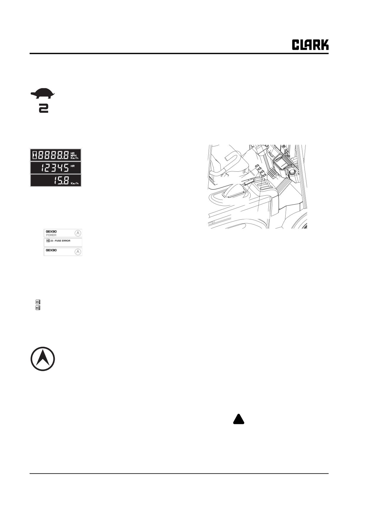
• Release the control lever. It should return to neutral
without binding. The pump motor should turn off.
The traveling speed of truck is limited to
The control lever should not bind when moving it
set speed.
to any position.
The upper mark is slow speed operating
• Repeat procedures with tilt control lever. Forks
icon, and the figure shows the limited
should tilt evenly and smoothly.
max. speed. (In upper example, the lim-
ited max. speed is 2km/h)
• If lift truck is equipped with an attachment, test the
auxiliary control lever for a correct function.
Hourmeter & Speed
• Briefly operate the attachment.
• It displays the accumulated oper-
ating hour and traveling speed of
truck.
• When the traveling speed is less
than 0.5km/h, it displays the accu-
Lift lever
mulated operating hour.
• When the traveling speed is more
than 0.5km/h, it displays the traveling speed.
Tilt lever
Option lever
Message display
The model name, POWER
Normal
selection, travel direction, warn-
4.
Check Drive Motor (Brake) Cut-Off Switch
Error
ing and error message are dis-
• Move the truck forward slowly. Slowly depress
Warning
played.
BATTERY LOW
brake pedal. Drive motor should cut off before the
• In normal operating condition:
brakes apply.
Model name/POWER/Travel direction
• If operation is not satisfactory, DO NOT operate
•
When several messages are simultaneously dis-
the truck. Take truck out of service and report con-
played, it will be displayed in the order of Error,
dition to designated authority.
Warning and Normal condition.
• If many error conditions are
5.
Check Upright
23 : FUSE ERROR
simultaneously
occurred,
the
• Note any excessive “slop” or “noise” in the
56 : FET SHORT
priority 2 Errors will be displayed.
upright. It may indicate roller damage, or that
(The priority means Error number)
roller shimming, repair or adjustment may be
required.
Travel direction icon
6.
Check Tilt Cylinder (Refer to Group 32 to do the
• It displays the traveling direction or angle of
following)
steering wheel..
• Perform drift test.
• The direction icon rotates in 10 degrees.
• Perform check and adjustment procedure.
(Total 36 icon)
• Check rod seal condition.
Error icon
• Check mounting. Tighten as needed.
• Check rod end. Tighten as needed.
• When error occurs this icon is displayed to distin-
guish the condition easily. When the error message
7.
Check Truck Performance
is displayed, this icon is simultaneously displayed.
3. Check Function Control Levers
!
WARNING
• Gently pull back on the lift control lever. The pump
Check all around to be sure that your
motor should turn on and the carriage should begin
intended path of travel is clear of obstruc-
to elevate.
tions and pedestrians.
PS-2-6 • Planned Maintenance
SM 765, Nov ’06
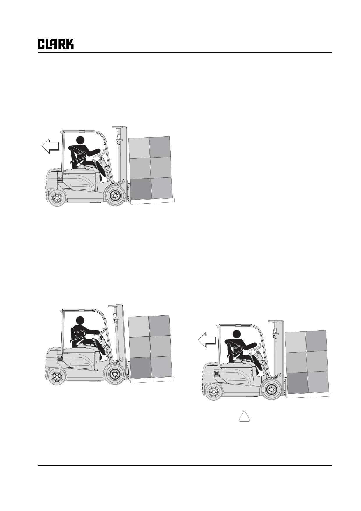
Group PS, Periodic Service
• Drive the truck forward in a straight line at a high
2. Operaten the truck at a slow speed in a forward direc-
rate of speed. Listen for unusual drive train noise.
tion of travel. Reverse direction of travel. The truck
Stop truck.
should slow down to a smooth controlled stop, and
accelerate normally in the opposite direction.
• Check acceleration from a stop to top travel speed.
Acceleration should be smooth without hesitation.
If plugging is as specified, then repeat the procedure
Stop the truck. Repeat procedure in reverse.
at high speed. The truck should come to a smooth
controlled stop in approximately 20 feet (6.10 mm)
• Report condition on PM report form.
with accelerator in maximum travel position.
3. Repeat the procedure at high speed with the direction
lever moved in reverse direction.
If plugging (braking) is not as specified, refer to the
adjustment instructions in Group 19 of this manual.
Report condition to designated authority.
Check Accelerator
1. After checking to see that you have a clear path
ahead, drive the truck in a straight line at a high rate
of speed in a forward direction of travel. Listen for
unusual drive train noise. Stop truck
Test Drive Truck with Load
2. Check acceleration from a stand still condition to top
travel speed. Acceleration should be smooth without
NOTE
hesitation.
Conduct these tests with a rated capacity
3. After checking to see that you have a clear path
load, if possible.
behind, drive the truck in reverse. Check acceleration
from stand still condition through top travel speed.
Test the truck for proper operation and drive train function
Acceleration should be smooth.
by driving the truck in both the forward and reverse direc-
tions. Drive first in a straight line and slowly through a
Check the accelerator pedal while conducting the speed
series of full right and left turns. Then repeat, driving in
range tests. It must move easily and smoothly throughout
the acceleration stroke and return without binding. There
opposite direction.
should be no restriction to movement on either accelera-
tion or deceleration.
Carry Load Low & Tilt Back
Test for correct function of the transistor control.
!
CAUTION
Check Controlled Plugging (Braking)
DO NOT operate lift truck if the brakes are
1. Operate the truck with parking brake set. It should
not operating properly. Use only brake fluid,
not move. Release parking brake.
SAE J1703 DOT 3, for ECX / EPX brakes.
SM 765, Nov ’06
Planned Maintenance • PS-2-7
Group PS, Periodic Service
Test the service brake (drive motor cut-off) switch. Drive
shifting from NEUTRAL to REVERSE, then back to
the truck FORWARD (or in REVERSE) at creep speed.
NEUTRAL. Check for positive control action when
While holding the accelerator pedal steady in creep speed
changing directions.
position, depress brake pedal. The braking action should
Listen for clunking, squealing, grinding, scraping, or other
interrupt power to the drive motor and stop the truck.
unusual noises. Check for vibration. Listen for wheel
Release the brake pedal. The drive motor should again
bearing or other specific running noise.
start moving the truck.
Lift Mechanism and Controls
NOTE
Conduct these tests with a rated capacity load.
Test the operation of the hydraulic system and upright.
Brake Pedal
Accelerator Pedal
Test brake operation by depressing and releasing the brake
pedal several times while driving the truck. The brakes
should bring the truck to a smooth stop without pulling,
squealing, or shuddering. Have the brakes adjusted or
repaired as necessary. Drive motor should cut off before
brakes apply.
To check brake holding capability and adjustment, park
the truck on a grade and depress brake pedal. The brake
should hold a lift truck with rated load on a 15% grade.
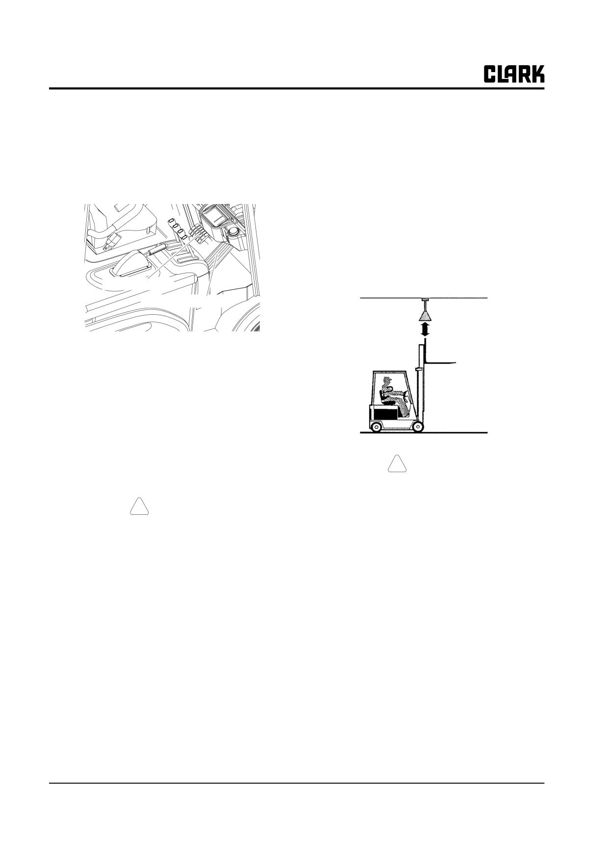
!
CAUTION
Check Steering
Be sure there is adequate overhead clearance
before raising the upright.
! CAUTION
Cycle (raise to full height and then lower) the upright at
DO NOT operate lift truck if steering system
both slow and fast speed, with the upright tilted slightly
is not operating properly.
backward. Watch the upright assembly as it rises. All
movements of the upright, fork carriage, and lift chains
Check steering control operation. First, drive the truck in a
must be even and smooth, without binding or jerking
straight line. The truck must drive in a straight line with-
motions. Watch for chain wobble or looseness. The chains
out drifting toward either side. Then drive slowly (creep
should have equal tension and move smoothly, without
speed) through a series of full right and left turns. Check
noticeable wobble.
steering response and smoothness of operation. Turning
effort must be the same in either direction. You will hear
Check function of the control lever and main hydraulic
the hydraulic pump operate over relief when in a full turn.
valve. Listen for abnormal noises in the hydraulic valve,
If there is a steering problem, have it repaired.
main hydraulic pump, and system components.
NOTE
If the maximum fork height is not reached, either the fluid
Conduct the following test with a rated
level in the hydraulic sump tank is low, or there is severe
capacity load.
binding within the upright.
Test for general drive train operation. Drive the truck at
various speeds and operating conditions, in both FOR-
WARD and REVERSE directions. Test shifting from
NEUTRAL to FORWARD, then back to NEUTRAL. Test
PS-2-8 • Planned Maintenance
SM 765, Nov ’06
Group PS, Periodic Service
Test for correct tilt cylinder rod adjustment. Raise the car-
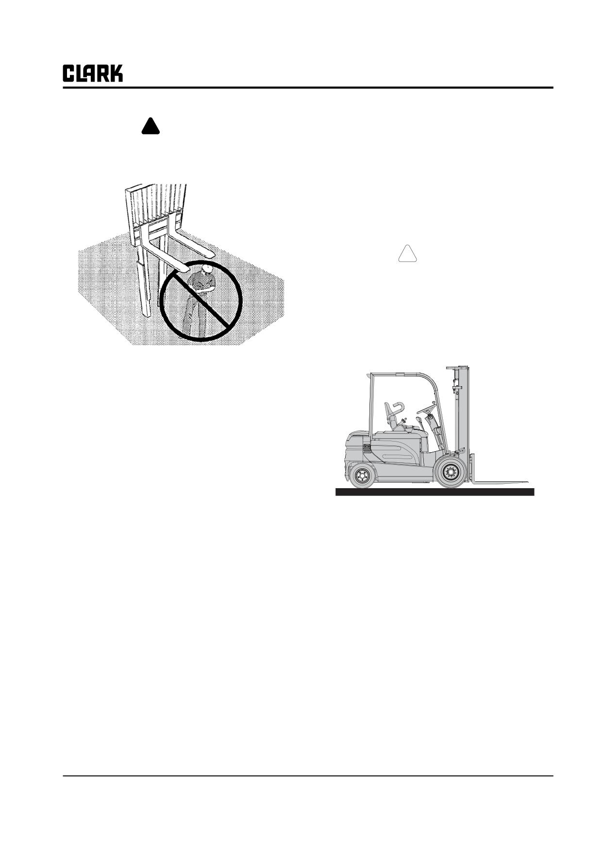
! WARNING
riage to an intermediate position. Tilt the upright fully for-
FALLING FORKS. Do not walk or stand
ward without a load on the forks. Check for upright
under raised forks. The forks can fall and
racking (twisting) as the tilt cylinders reach the end of
their stroke. Tilt the upright fully back. The upright should
cause injury or death.
not rack (twist) when the tilt cylinders reach the end of
their travel. If forward upright racking is found, adjust-
ment of the tilt cylinder rod ends (yokes or spacers) is
required. If backward racking is found, adding or remov-
ing shims is required. Refer to Group 32.
!
CAUTION
When you have completed the operational
tests, park and leave truck according to stan-
dard shutdown procedures.
Never Walk Under Raised Forks!
Check the upright rails, rollers, carriage, lift chains, and
cylinders as they move. Watch for binding or excessive
freeplay (looseness) between the carriage and the upright
rails and rollers. Listen for abnormal noises. If there is
excessive clearance between the rails and channels, the
upright roller needs adjustment. If the rails or carriage
bind or hesitate when lowering, the rollers are either dam-
aged or roller adjustment is incorrect.
Check the upright for excessive downdrift. Stop the fork
carriage in an intermediate position. Check that it holds its
position without moving down. If you observe downward
movement (drift) or have a report of a drift problem, the
lift cylinder seals may be worn. With forks elevated, turn
Standard Shutdown Procedures:
key switch off. Pull back on the lift lever. The forks should
• Come to a complete stop.
not lower This tests the check valve.
• Park only in authorized locations.
Test the tilt function. Check for excessive tilt cylinder
• Lower the forks fully, tilt upright forward until fork
drift. Stop the upright at a position near vertical. Check
tips touch floor.
that the upright holds its position without moving forward.
• Allow travel control to return to neutral.
If you observe forward movement (drift) or have a report
of a tilt drift problem, the tilt cylinder seals may be worn.
• Turn the key switch OFF.
• Apply the parking brake.
Check fork height adjustment and carriage chain adjust-
ment. Tilt the upright to the vertical position and fully
• Disconnect Battery
lower the carriage. The forks should stop and be held
approximately 13 mm (0.50 in.) above the floor. If the
Make a record of all maintenance and operating problems
forks hit the floor, the carriage lift chains should be
you find.
adjusted. Also check the rail chains.
If truck is equipped with an attachment, briefly operate
the attachment to check the controls for correct function.
SM 765, Nov ’06
Planned Maintenance • PS-2-9
Group PS, Periodic Service
Battery Compartment Inspection
Turn key switch OFF. Disconnect battery from truck
receptacle. Remove the control compartment cover from
Turn key switch OFF. Disconnect battery from truck
the counterweight.
receptacle.
Discharge the capacitor using a 10W~100W resistance
connected from the +Batt(pos.) to the -Batt(neg.).
Inspect the transistor controls for clean condition. Check
for oily dirt buildup on contactors, Inspect all control wir-
ing terminals for any obvious damage. Look for cracks or
worn areas in the wiring insulation. Check for loose con-
nections at the control terminals. Air-clean as necessary.
Treat the control panel plugs with Clark 1801145”Lectric-
Like” Spray or Clark 1803827-brush on cleaner.
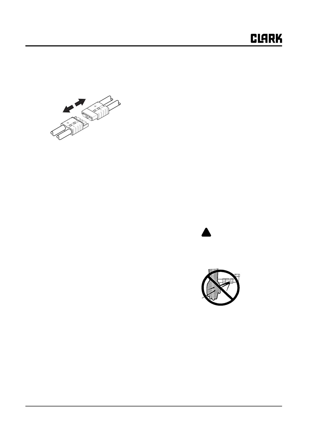
Inspect condition of the battery connector and truck bat-
Hydraulic Compartment Inspection
tery receptacle. Check the spring-loaded terminals, con-
Remove the floorplate.
nectors, and retaining tabs. Look for poor connections due
to burning, bad crimps, or broken or loose retainers.
Check the condition of all hydraulic system components,
Check the molded body for damage from overheating,
hoses, piping, and connections. Check for wear, leakage,
burning, and chips or cracks. Replace receptacle terminals
and damage.
if pitted or corroded.
Remove the battery.
Inspect condition of the battery and cables. Check the bat-
Inspect the drive motor, hydraulic pump motor power
tery cables for wear or other damage. Check for signs of
cables. Check drive motor mounting fasteners. Check
interference or rubbing with other components. Be sure
hydraulic pump motor. Check pump motor mountings.
that the cable terminals are tight and clean. Clean off any
deposits of corrosion found on the battery.
!
DANGER
Never wash the battery when it is in the truck.
HYDRAULIC FLUID PRESSURE: Do not
Check battery post terminals for corrosion and damage.
use your hands to check for hydraulic leak-
Clean all corrosion from cable end and battery post.
age. Fluid under pressure can penetrate your
Check tighmess of cable and post terminals.
skin and cause serious injury.
If necessary, check the state-of-charge condition of the
battery. Take a specific gravity test of the electrolyte with
a hydrometer. Be sure to check a minimum of six battery
cells.
Check the electrolyte level of the battery. Add distilled
water, as required, to fill each cell to the correct level.
Check to be sure the vent hole in each battery cell cap is
open. If cap vents are plugged with corrosion, remove the
Brake Shoe and Drum Inspection
caps and wash in a solution of baking soda and water.
The brake linings, drum and adjustment setting can be
Refer to Group 12, Battery, for additional information.
inspected without removing the drum or hub. Refer to
Group 23, Section 6 for inspection procedure.
Motor Transistor Controls Inspection
IMPORTANT
Do not clean electrical components with
steam. Only approved solvents should be
used to clean controls.
PS-2-10 • Planned Maintenance
SM 765, Nov ’06
Group PS, Periodic Service
CLEANING
Cleaning Summary
* Battery Compartment.
* Hydraulic Compartment
* Drive Motor and Steer Motor.
* Pump Motor.
* Axle Mounting
* Control Compartment
* Upright.
IMPORTANT
Do not clean electrical components with steam. Only approved solvents should be used to clean Solid
State components. Scheduled cleaning (as outlined) should preclude the need for using a degreaser. Not
all degreasers are acceptable. If a degreaser is to be used, we recommend degreaser or the equivalent to
MS-180 Freon TF degreaser and cleaner.
! WARNING
When cleaning with compressed air:
• Wear eye protection and protective clothing when cleaning or drying with air pressure.
• Reduce air pressure to 30 PSI (207 kPa). Debris removed with air pressure can cause injury.
Normal Cleaning
Blowing dirt off with an air hose periodically will, for the most part, eliminate any serious cleaning problems. Should the
need arise for a more thorough cleaning, water may be hosed over the control and if necessary a mild detergent applied
such as that used in washing dishes in the home. This detergent should be rinsed off and the control dried with an air hose.
The control must be thoroughly dry before putting the truck back into service.
IMPORTANT
Cleaning the components of the truck is a vital part of the P.M. process. Keeping the components clean
will increase their service life and assure trouble free truck operation.
SM 765, Nov ’06
Planned Maintenance • PS-2-11
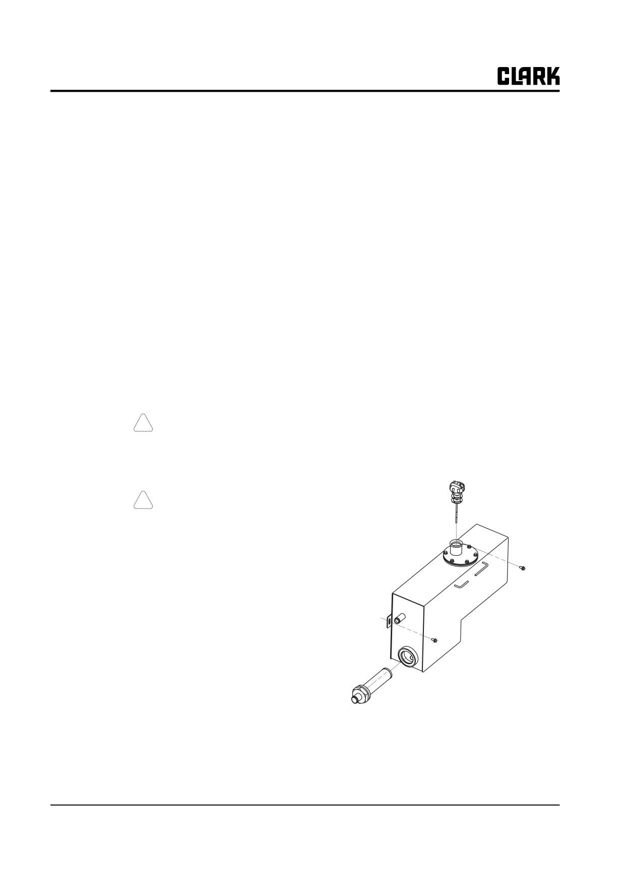
Group PS, Periodic Service
ponents which directly support, handle or control the load,
Air-Cleaning
or protect the operator.
Always maintain a lift truck in a clean condition. Do not
Check torque of critical items, including: overhead guard,
allow dirt, dust, lint, or other contaminants to accumulate
drive axle mounting, drive and steering wheel mounting,
on the truck. Keep the truck free from leaking oil and
counterweight mounting, load backrest extension, tilt cyl-
grease. Wipe up all oil spills. Keep the controls and floor-
inder mounting and yokes, upright mounting and compo-
board clean and dry. A clean truck makes it easier to see
leaks and loose, missing or damaged parts, and will help
nents. Refer to Group 40 for torque specifications.
prevent fires. A clean truck will run cooler.
The environment in which a lift truck operates will deter-
Lubrication, Fluids, and Filters
mine how often and to what extent cleaning is necessary.
For example, trucks operating in manufacturing plants
Hydraulic Sump
which have a high level of dirt or lint (e.g., cotton fibers,
Check the hydraulic sump tank fluid level. Correct fluid
paper dust, etc.) in the air or on the floor, will require
level is important for proper hydraulic system operation.
more frequent cleaning. If air pressure does not remove
heavy deposits of grease, oil, etc., it may be necessary to
Low fluid level can cause pump damage. Overfilling can
use steam or liquid spray cleaner. DO NOT clean electri-
cause loss of fluid or lift system malfunction.
cal components with steam.
Hydraulic fluid expands as its temperature rises. Check
NOTE
the fluid level at operating temperature, after approxi-
mately 30 minutes of truck operation. To check the fluid
See special provision for blowing dust from
level, park the truck on a level surface. Put the upright in a
pump and drive motors on page 14 of this
vertical position and lower the fork carriage fully down.
section.
Remove the floorplate and observe the fluid level marking
on the sump tank. Refer to Group 29, Section 1 for more
! CAUTION
information on the sump tank. DO NOT overfill.
Battery must be disconnected and capacitors
Check the condition of the hydraulic fluid for color, clar-
discharged before inserting air wand through
ity, and contamination. Change (replace) the hydraulic
access holes.
fluid as necessary.
! CAUTION
Wear suitable eye protection and protective
clothing.
Lift trucks should be air-cleaned at every PM interval, and
as often as required.
Air-cleaning should be done using an air hose with special
adapter or extension having a control valve and nozzle to
direct the air properly. Use clean, dry, low-pressure com-
pressed air. Restrict air pressure to 207 kPa (30 psi).
Air-clean the following: upright assembly; drive axle; bat-
tery, cables, switches and wiring harness; transistor con-
trols and wiring; drive and hydraulic pump motors;
steering axle and steering cylinder.
Critical Fastener Torque Checks
Fasteners in highly loaded (critical) components can
Hydraulic Fluid and Filter Change
quickly fail if they loosen. Loose fasteners can cause dam-
age or component failure. For safety, it is important that
Drain and replace the hydraulic sump fluid every 2000
the correct torque be maintained on all fasteners of com-
operating hours, or sooner, as required. Replace the
PS-2-12 • Planned Maintenance
SM 765, Nov ’06
Group PS, Periodic Service
hydraulic fluid filter at every fluid change. Replace the
Drive Axle Fluid Change
sump tank breather/fill cap every 1000 operating hours.
NOTE
NOTE
Check the PM interval (operating hours), or
Always use genuine Clark Parts.
the condition of the fluid to determine if the
drive axle fluid needs to be changed.
Sump Tank Breather Maintenance
Drain and replace the drive axle fluid every 2000 operat-
Remove the sump tank fil cap/breather and inspect for
ing hours. The fluid should be drained when it is at operat-
excessive contamination and damage. Clean and replace
ing temperature. Put the truck in a level position. Block
as recommended by the PM schedule, or as required by
the wheels to prevent truck from moving.
operating conditions.
Inspect and clean the drive axle breather (air vent)
mounted on top of drive axle.. Refer to Lubrication Chart
and Group 40.
Access to the Drive Axle
Truck Chassis Inspection and Lubrication
Access the Drive axle by removing the floorplate or
through the upright.
Lubrication and inspection of truck chassis components,
including steer wheels and wheel bearings, will be easier
! WARNING
if the rear of the truck is raised and blocked up under the
frame. Refer to Group SA, Section 2, for additional infor-
An upright or carriage can move unexpect-
mation.
edly. Chain or block the carriage and rails.
Failure to follow this warning can result in
IMPORTANT
serious injury or death.
Do not raise truck by lifting under the coun-
terweight.
Refer to Group SA, Section 2 for additional information
on supporting the upright.
!
WARNING
Block the wheels. Be sure to put blocking under the car-
riage and upright rails.
Be sure to put blocking under the frame to
keep the truck safe.
Drive Axle Fluid
Be sure to clean the grease fittings before lubricating.
Remove excess grease from all points after lubricating.
Check the drive axle fluid level with the truck on a level
surface and fluid at operating temperature.
Upright and Tilt Cylinder Lubrication
Remove the fluid level inspection plug located on the left
side of the drive axle housing. Fluid level should be at the
Clean the fittings and lubricate the tilt cylinder rod end
bottom of the inspection hole. If fluid level is low, add
bushings.
enough fluid to bring fluid level up to bottom of the
inspection hole. DO NOT overfill.
Clean the fittings and lubricate the upright trunnion bush-
ings (one fitting on top of trunnion, each side).
Add the recommended fluid only, as required.
Inspect the fill plug for damage. Replace as needed. Install
Lift Chains
and tighten the plug.
Lubricate the entire length of the rail lift and carriage
chains with Clark Chain and Cable Lube.
SM 765, Nov ’06
Planned Maintenance • PS-2-13
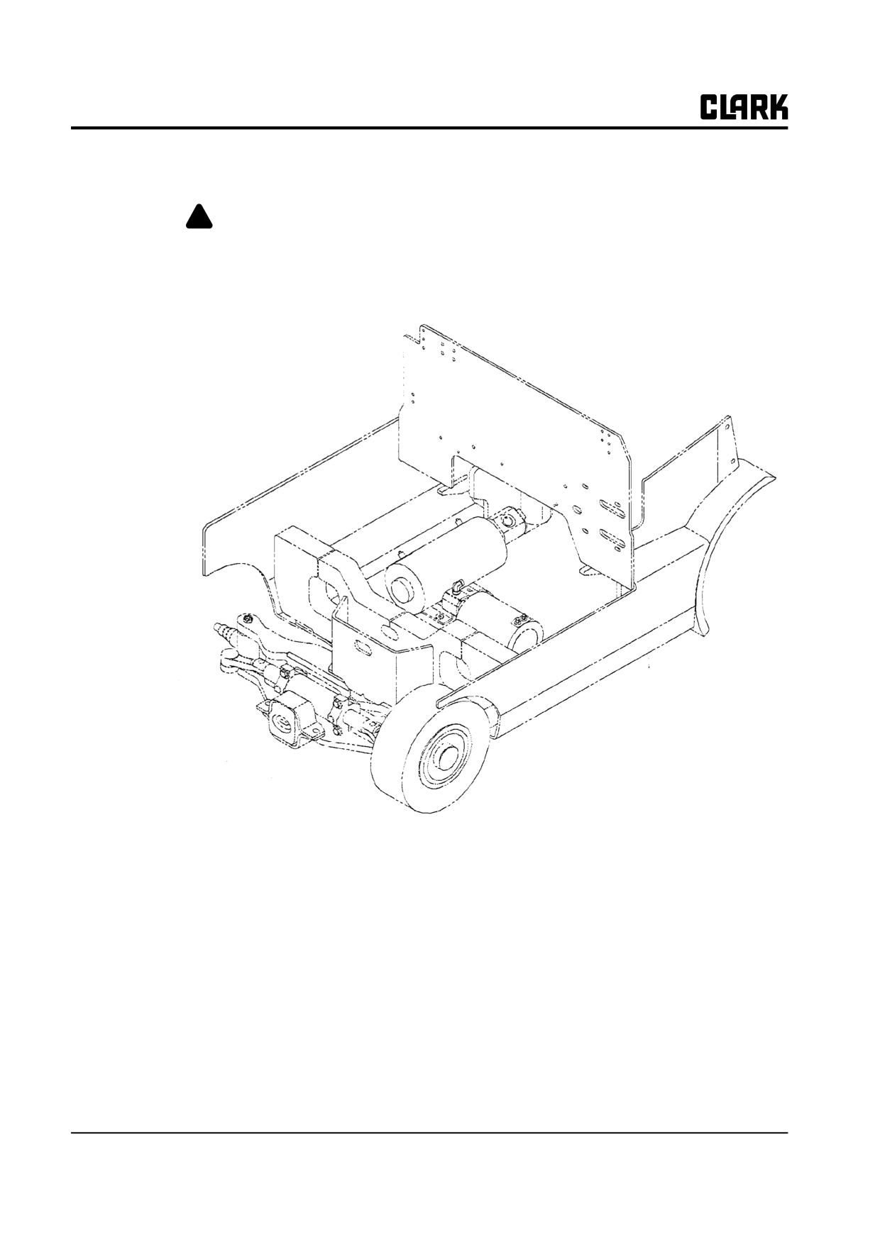
Group PS, Periodic Service
Air Cleaning of Motors
tors by using a
10W~100W resistance
connected from the +Batt(pos.) to the
-
Batt(neg.).
! WARNING
Before inserting metal air cleaning wand, dis-
connect the battery and discharge the capaci-
PS-2-14 • Planned Maintenance
SM 765, Nov ’06
Group PS, Periodic Service
Section 3
The PM Inspection Form
• As an aid to service technicians performing and
• Use this form as a checklist, and make a record of
documenting PM inspections, Clark has prepared
your inspection and truck condition. Note the spe-
an Electric Truck Planned Maintenance Report
cial coding system for indicating the importance of
form. (Sample appears on the next page.)
needed repairs and/ or adjustments.
SM 765, Oct ’06
The PM Inspection Form • PS-3-1
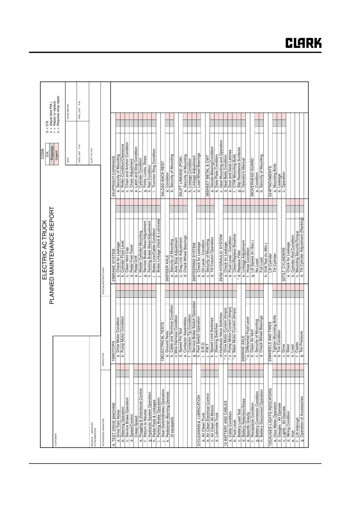
Group PS, Periodic Service
PS-3-2 • The PM Inspection Form
SM 765, Oct ’06
GROUP 12 BATTERY
GROUP 12
BATTERY
Battery Service
Section 1
SM 765, Nov ’06
Group 12 BATTERY
NOTE :
Group 12 BATTERY
SM 765, Nov ’06
Group 12, Battery
Section 1
Battery Service
Battery Handling
2
Battery Removal
3
Battery Maintenance
4
Maximum Battery Life
4
Battery Vents
4
Battery Cleaning
5
Battery Charging
5
Battery Electrolyte
5
CleanBattery Compartment
5
Replacement Batteries
5
Battery Installation
5
Keeping Battery Records
6
Battery Tests
6
Specific Gravity Test
6
Load Test
6
SM 765, Nov ’06
Battery Service • 12-1-1
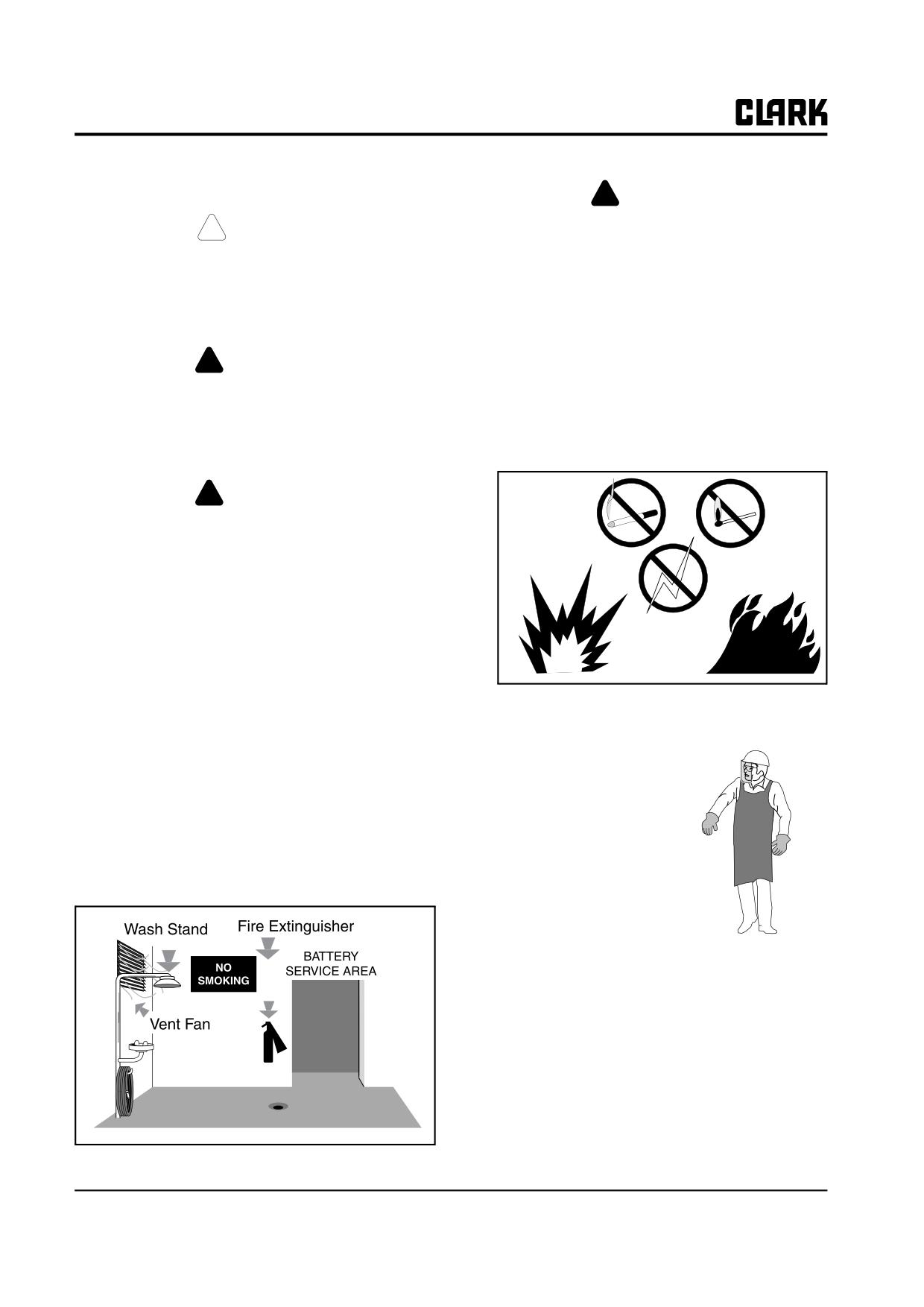
Group 12, Battery
Battery Handling
!
DANGER
Explosive gas is always present around bat-
! CAUTION
teries, especially when they are being
Remove all jewelry (watch, rings, bracelets,
charged.
etc.) before working on electrical systems.
Severe burns can result from contact with
• No smoking allowed in the charging area.
electrical circuits.
• Battery electrolyte must never be checked with
an open flame.
! WARNING
• Open flame, sparks, or electric arcs must never
be allowed in the battery charging area.
Battery service must be done by trained per-
sonnel. Battery acid can cause severe burns
• The battery contains corrosive sulfuric acid
and injury. Do not smoke or have open
which can cause injury. If acid contacts your
flames around batteries.
eyes or skin, flush immediately with water and
get medical assistance.
! WARNING
Electric truck batteries are heavy and awk-
ward to handle. On charge, they give off
hydrogen and oxygen which, in certain con-
centrations, are explosive. Electric truck bat-
teries are also costly, so before you remove,
service, or install a truck battery, consult
BATTERY MANUFACTURER for more rec-
ommendations and instructions on handling
and charging batteries. Carefully read and
follow recommendations and instructions.
Persons maintaining batteries must wear protective cloth-
ing such as:
Change or service batteries only in an area designated for
this purpose. Refer to page 4 for additional information.
• Face and head shields
• Be sure this area has provisions to flush and neu-
• Long shirt sleeves
tralize acid spillage.
• Gauntlet gloves
• Be certain the area has proper ventilation to venti-
• Rubber apron
late fumes from charging batteries.
• Check to see that there is fire protection. Fire extin-
guishers should be properly maintained and
located in designated areas.
12-1-2 • Battery Service
SM 765, Nov ’06
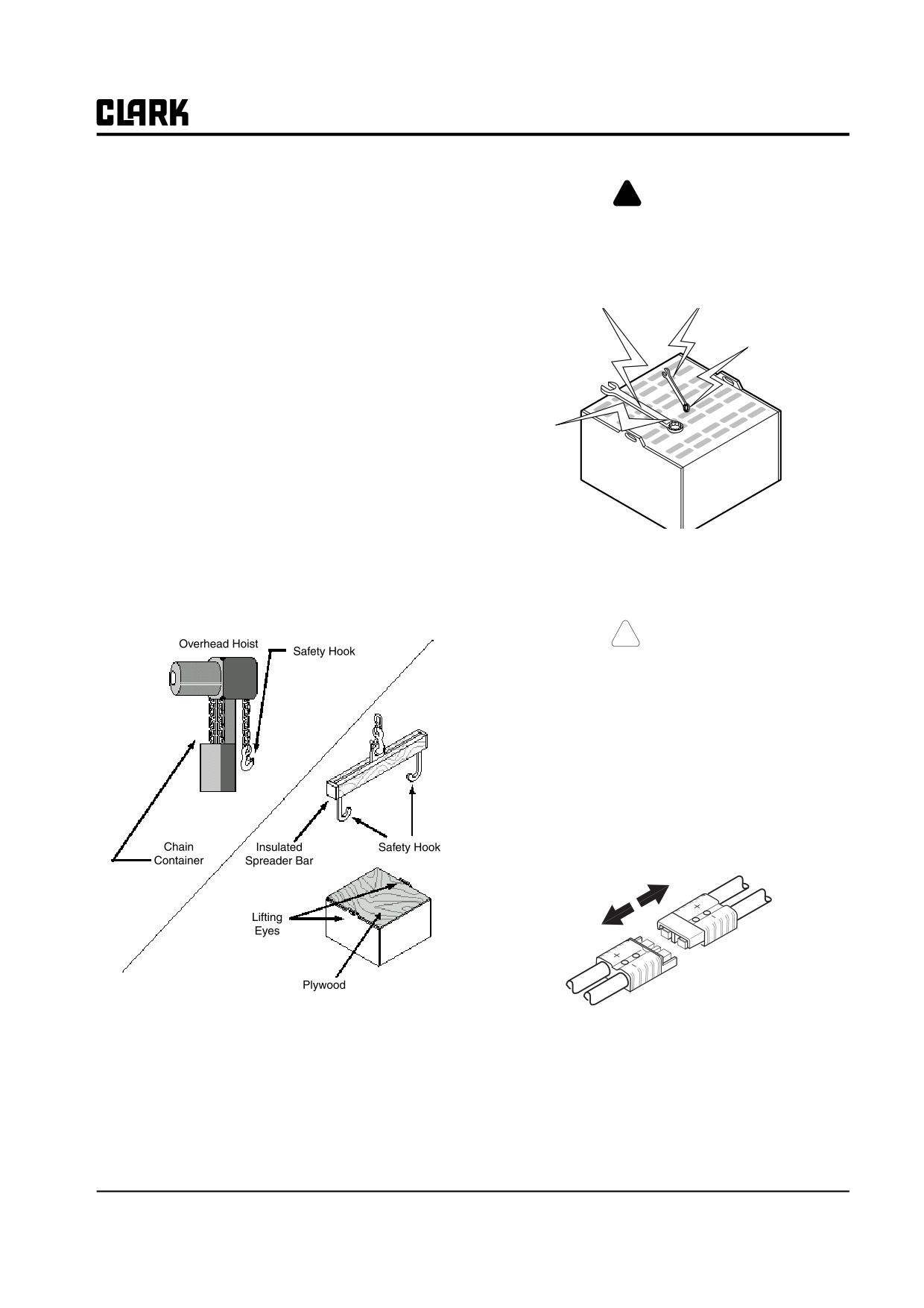
Group 12, Battery
Be sure the battery service area is equipped with material
!
DANGER
handling equipment designed for the purpose of removing
and replacing batteries, such as a conveyer or overhead
Never lay tools or other metal objects on a
hoist equipped with safety hooks.
battery. Metal objects contacting battery ter-
minals will cause short circuits. The shorted
IMPORTANT
circuits could ignite battery fumes and cause
To prevent side forces from damaging the
the battery to explode.
battery, the distance between the lifting
hooks (of the spreader bar) must be adjusted
to the same dimension as measured between
the battery lifting eyes. Make sure the lifting
hooks are the correct size to fit the lifting eyes
of the battery.
• When using an overhead hoist, be sure to use an
insulated spreader bar or similar lifting device.
• Be sure the hoist is equipped with a chain container
to accumulate excess lifting chain. When this is not
possible, be sure the battery is covered with a non-
conductive material, such as plywood, as shown
below.
Battery Removal
• If the battery does not have a cover of its own,
cover it with a non-conductive material such as
1.
Move truck to the designated battery service area.
plywood.
! CAUTION
SAFE PARKING. Before working on truck:
• Park truck on a hard, level and solid surface, such
as a concrete floor with no gaps or breaks.
• Put upright in vertical position and fully lower the
forks or attachment.
• Put all controls in neutral. Turn key switch OFF
and remove key.
• Apply the park brake and block the wheels.
2.
Turn key switch OFF and disconnect battery.
SM 765, Nov ’06
Battery Service • 12-1-3
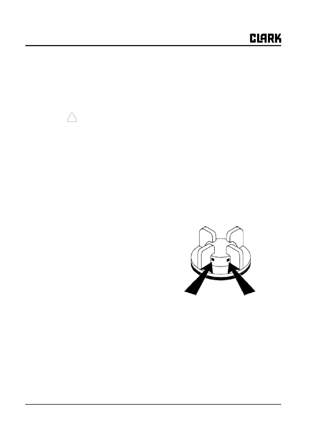
Group 12, Battery
3. Lift and latch seat deck to access battery.
age andcould ignite battery fumes, causing the bat-
tery to explode.
4. If the battery to be handled is uncovered, cover bat-
• Maintain good battery cable connections.
tery with a non-conductive material (plywood, heavy
cardboard, etc.) prior to removal from truck.
• Check power cables and wiring for damage that
can cause premature drainage of the battery.
IMPORTANT
• Do not overcharge a battery.
Do not wash battery in truck.
• Do not undercharge a battery.
• Follow the instructions provided by the supplier(s)
! CAUTION
of the battery and battery charging equipment.
An overhead hoist of sufficient lifting capac-
• Maintain accurate battery records. If battery trou-
ity (refer to “Weights” in Group 40) should
bles occur, these records will help you and your
be used to lift battery. The safety hooks of the
battery representative determine the nature of the
insulated spreader bar should be attached to
problem.
the lifting eyes provided in the battery casing.
Battery Vents
5. Be sure battery is covered. Attach lifting device. Lift
and remove battery.
•
When Charging Batteries: The vent caps must be
kept in place to avoid electrolyte spray. Care must
Battery Maintenance
be taken to assure that vent caps are functioning.
The vents must be open to allow the battery to
NOTE
breathe. The battery cover must be removed/
To obtain maximum performance and bat-
opened to dissipate heat and explosive gas.
tery life, follow the instructions supplied by
•
When Cleaning Batteries: The vent caps must be
your battery vendor.
tightly in place.
Industrial batteries are used to supply the electrical power
to operate an electric industrial truck. Their voltage
depends on the number of individual cells they contain.
There are approximately two volts for each cell in the
commonly used lead-acid type battery. Batteries normally
range from 6 volts to 72 volts. Their capacity varies
depending on the application. Only use batteries that com-
ply with factory specifications as to size and capacity.
Maximum Battery Life
• Do not add acid to a battery. Only qualified battery
representatives should determine if this is neces-
sary.
• When lifting a battery, use a lifting device designed
for this purpose.
• Check the electrolyte level after placing a battery
on charge. The electrolyte level in a battery should
be slightly below the lower lip of the filling hole
vent. Do not overfill. Overfilling causes loss of
electrolyte.
• Keep the battery clean, dry and in good condition.
• Keep metal objects and tools away from the top of
the battery. Short circuits will cause battery dam-
12-1-4 • Battery Service
SM 765, Nov ’06
Group 12, Battery
Battery Cleaning
Clean Battery Compartment
The easiest and most satisfactory method of cleaning a
. Using baking soda and water solution, clean the walls
battery is to wash it with a low-pressure cold water spray.
and floor of the compartment. Rinse with clear water.
The battery top can also be washed with a baking soda
. Blow off the compartment walls and floor with an air
solution and rinsed with clear water.
hose. Allow to air-dry.
IMPORTANT
. Remove battery from truck before washing.
!
CAUTION
• Vent caps must be free of obstruction and in
Wear eye protection and protective clothing
good condition.
when cleaning or drying with compressed air.
• Battery top should be clean and free of cracks
Reduce air pressure to 207 kPa (30 psi).
or breaks.
Debris removed with air pressure can cause
• Battery terminals must be clean and solidly
injury.
mounted.
• Damaged batteries should be repaired or
replaced. Consult your battery vendor.
• Check to be sure all vent caps are tight before
washing the battery.
• Fill a bucket with cold water. Add a box of baking
soda to the bucket. Stir the solution until dissolved.
Keep this solution around the battery service area
at all times.
• After washing battery, thoroughly rinse with clear
cold water.
Replacement Batteries
Battery Charging
!
CAUTION
Follow the instructions supplied by the battery charger
vendor.
Use a battery properly sized to the dimen-
sions of the battery compartment. Batteries
too small can shift and cause damage to the
Battery Electrolyte
truck or injury to the operator or bystanders.
• Check with battery manufacturer’s documentation
Only use batteries that comply with factory
before working on battery electrolyte.
recommendations as to size and capacity.
• Always use a carboy tilter or siphon when handling
battery electrolyte.
Battery Installation
• When mixing electrolyte, always pour acid into
If the battery is uncovered, cover the battery with a non-
water-NEVER pour water into acid. Pouring water
conductive material (i.e., plywood, heavy cardboard, etc.)
into acid will cause a dangerous chemical action or
prior to installation.
splash.
• Using an overhead hoist and insulated spreader bar,
lift battery into battery compartment.
• Install battery retainer, if applicable.
• Remove non-conductive material from battery.
• Connect battery to truck.
SM 765, Nov ’06
Battery Service • 12-1-5
Group 12, Battery
Keeping Battery Records
Battery Tests
Records should be maintained to get the best service out
NOTE
of your battery and truck.
Use both tests described here.
These records should contain:
Specific Gravity Test
• Test Date. Each test should be dated for future ref-
erence and comparison.
Test at least six cells across battery with a temperaturecor-
• Specific Gravity and Temperature Readings.
rected hydrometer (see chart). Battery is fully charged
Each battery cell should be checked and recorded
when the reading falls in the 1.280 to 1.300 range. If the
before and after charging. The specific gravity
difference between cells is more than .015, battery needs
reading of the electrolyte, calculated using a multi-
maintenance.
plier to account for the ambient temperature,
should not be less than 1.260. If below 1.250, the
SPECIFIC GRAVITY TEST
battery should be recharged and tested.
SPECIFIC GRAVITY
STATE OF CHANGE
• Variation Between Each Cell Tested. The varia-
1.260~1.300
100% CHARGED
tion in specific gravity reading between cells
1.230~1.250
75% CHARGED
should not be greater than 15 points (0.015). If
1.200~1.220
50% CHARGED
readings are greater, there are defective cells.
1.170~1.190
25% CHARGED
NOTE
1.140~1.160
VERY WEAK
The pilot cell should be changed occasionally
1.110~1.130
DISCHARGED
to distribute any electrolyte loss over the bat-
tery when taking readings.
The battery specific gravity is an indication of the bat-
tery’s state of charge. You can determine the specific grav-
• Load Voltage Tests should be performed and
ity of the electrolyte solution in a battery with an
recorded indicating the condition of a battery while
hydrometer. If the state of charge is low, the hydrometer
it is performing work.
will read low. If the state of charge is high, the hydrometer
• Actual Operating Hours of the Battery. Record
will read high.
the actual time the battery is in use before putting it
on charger.
For, example a reading from:
• Charging Time. Keep an accurate record of the
•
1.260 to 1.300 indicates a fully-charged battery.
actual time the battery is on charger. After each
•
1.200 to 1.220 indicates a battery is in a discharged
charge, check to see if the battery is fully charged.
condition and cannot give satisfactory service.
Test the battery before placing it back into service.
Record these results.
Load Test
• Visually Inspect for loose terminal connections or
posts, a cracked case, damaged cell covers (vent
Put the main hydraulic system into tilt by-pass while read-
caps), or excessive corrosion. This data should be
ing battery volts with a voltmeter.
noted to help determine work environment and
possible trouble areas.
Battery needs recharge or repair if voltage drops below
80% of the rated voltage of the battery.
Minimum acceptable readings:
•
80 volt battery: 64 volts
12-1-6 • Battery Service
SM 765, Nov ’06
GROUP 13 WIRING, SWITCHES, AND INSTRUMENTS
GROUP 13
WIRING, SWITCHES, AND INSTRUMENTS
Schematic Electric Circuit Diagrams
Section 1
General Electical Service Tips
Section 2
Wiring and Cables
Section 3
Switches and Sensors
Section 4
Instrument Panel
Section 5
SM 765, Nov ’06
Group 13 WIRING, SWITCHES, AND INSTRUMENTS
NOTE :
Group 13 WIRING, SWITCHES, AND INSTRUMENTS
SM 765, Nov ’06
Group 13, Wiring, Switches, and Instruments
Section 1
Schematic Electric Circuit Diagrams
Standard Truck
IN-28280
ELH Options Truck
IN-28294
SM 765, Nov ’06
Schematic Electric Circuit Diagrams • 13-1-1
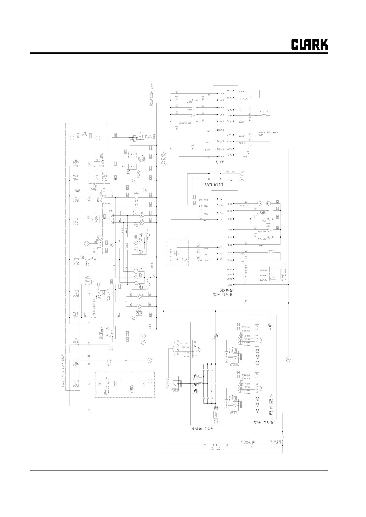
Group 13, Wiring, Switches, and Instruments
Standard Truck
13-1-2 • Schematic Electric Circuit Diagrams
SM 765, Nov ’06
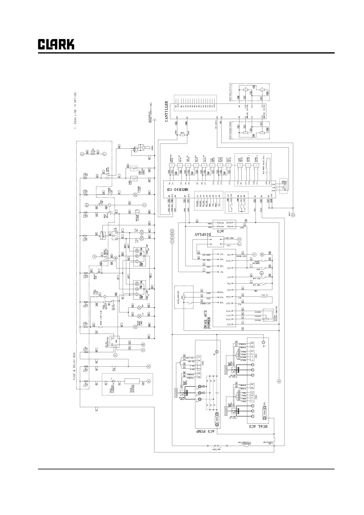
Group 13, Wiring, Switches, and Instruments
ELH Options Truck
SM 765, Nov ’06
Schematic Electric Circuit Diagrams • 13-1-3
NOTE :
Group 13, Wiring, Switches, and Instruments
SM 765, Nov ’06
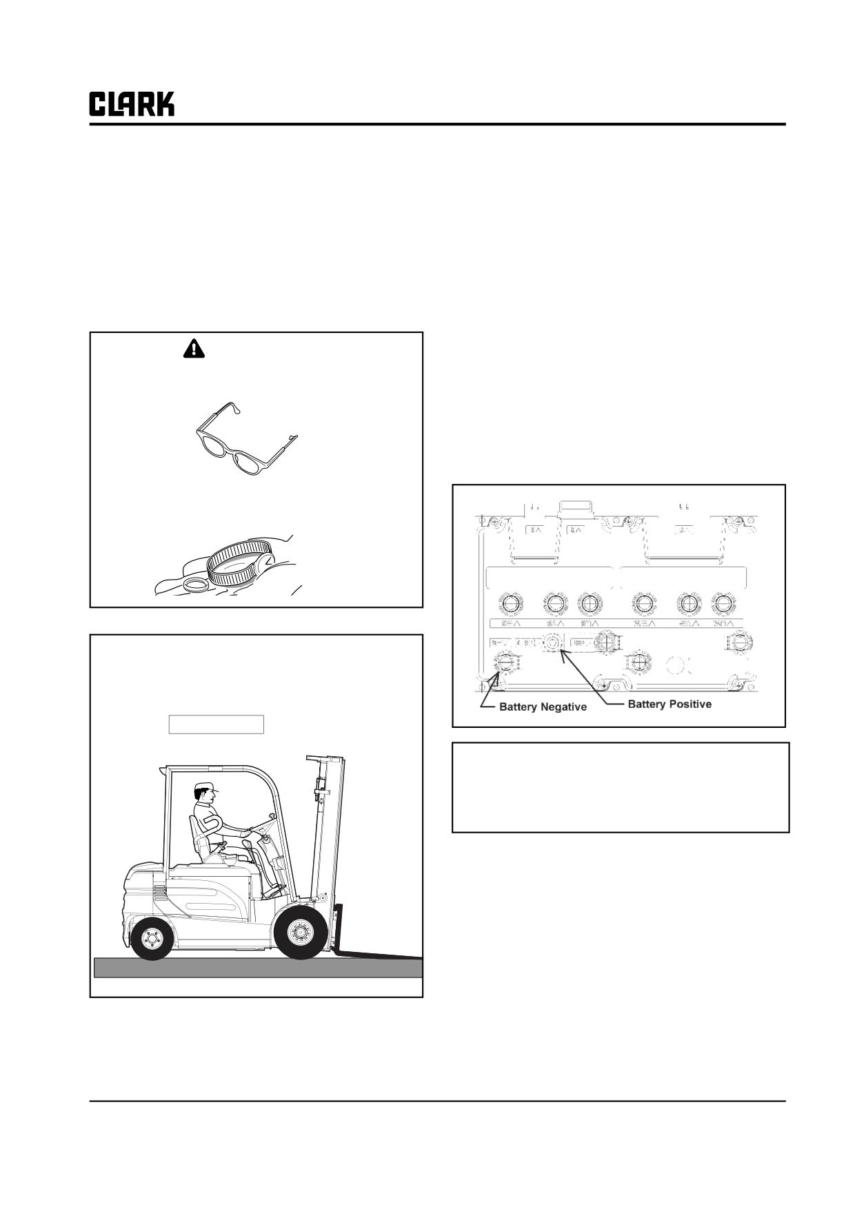
Group 13, Wiring, Switches, and Instruments
Section 2
General Electrical Service Tips
• Make sure battery is disconnected.
General Electrical Service Tips
3. Discharging Controller Capacitors
CAUTION
It is necessary to discharge the capacitors before you work
Always wear safety glasses.
on the controller.
NOTE
Make sure that the battery has first been dis-
connected at the battery receptacle.
Remove all jewelry before
working on truck.
1. Move truck to service area:
. Park truck on a flat level surface.
. Fully lower upright.
. Tilt forks forward until fork tips touch the floor.
SERVICE AREA
To discharge the capacitors connect a 200 ohm 10
watt resistor between the positive and negative
input post of the controller for 10 seconds.
2. Disable the truck:
• Turn the key switch to OFF.
• Remove key.
SM 765, Nov ’06
General Electrical Service Tips • 13-2-1
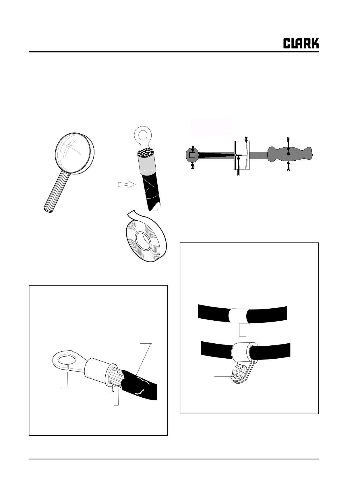
Group 13, Wiring, Switches, and Instruments
Checking Power Cables
Torquing Fasteners
Every cable and wiring harness on this truck is manufac-
Improperly torqued fasteners can cause damage
tured to an exact specification. A shorter cable or harness
Use an appropriate wrench and tighten all fasteners to the
will not fit. If either a harness or cable is routed improp-
torque specified in the following inspection procedures.
erly, it will not fit. Subsequently, electrical shorts and
damaged components may result if the replacement part is
the wrong one, or if it is routed incorrectly.
Pivoted
Scale
Handle
Socket
Head
Force or Pull
Pointer
Cuts
Typical Torque Wrench
Connecting and Mounting Compo-
Power cables having small cuts
nents
may be repaired with electrical
tape.
Tape markers are used to correctly position each
wire harness and electrical cable on the truck. When
correctly installed, the tape marker will be hidden by
Repairable Damage
the mounting clamp (guide). Be sure to follow the
instructions, where noted in this manual, when
installing a wire harness or electrical cables. If you
Cables having damage as shown in illustration below
do not, possible shorts and equipment damage may
should be removed immediately and replaced with
result.
new. Be certain the replacement cable is the exact
same length, size and has the proper connector. Make
absolutely certain the cable end is properly crimped
and its connection properly torqued upon installation
Tape Marker
Damaged Casing
Clamp
(and/or Guide)
Break
Markers on Wire Harnesses and Power Cables
Broken Wires
Cable Unfit for Further Service
13-2-2 • General Electrical Service Tips
SM 765, Nov ’06
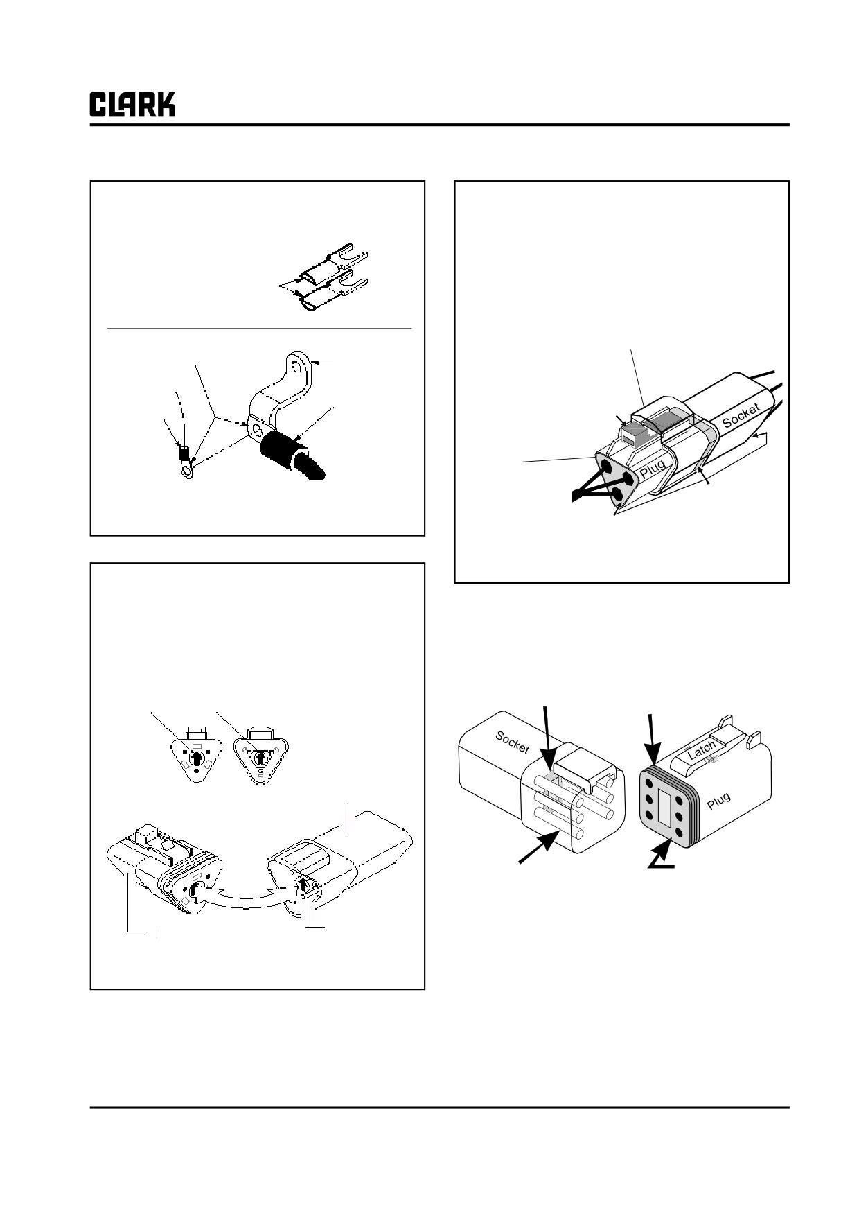
Group 13, Wiring, Switches, and Instruments
Multiple cable and wire connections must be con-
There is a moisture-resistant seal at each wireend of
nected as illustrated or electrical shorts and control
the connector and between the plug and socket.
damage may result.
Check seals for damage that would make them unfit
for furtherservice (cuts, etc.). Make certain the end
Terminal Barrels
seals are seated flush with the end of the connector
Must Face Opposite
housing. Make certain the plug and socket
Each Other
latchtightly to each other.
Firmly push plug into socket until
Assemble
latch "clicks" locking the two components
together.
Back to Front
Buss Bar
Barrel
Latch
Barrel
End seals
must be firmly
seated within
Seal(s)
the assembly
Multiple Connections
housing.
Seals and Latch
Connector Plugs and Receptacles are permanently
labeled with the proper PL (Plug) and SO (Socket/
Receptacle) number for easy identification. Match the
plug number with the appropriate receptacle number
Retainer plates snap into place to secure the pins and
before making a connection. If you do not, electrical
their sockets.
shorts and possible damage to the equipment may result.
Check the plates and seal for damage and secure
i.e., Plug #PL-6 plugs into pin socket #SO-6, etc.
mounting.
Pin Lock (Arrows must point in direction shown.)
Retainer Plates
Rubber Seal
SO-6 Socket
Retainer Plates
Pin
Retainer Plates
Pin(s)
PL-6 Plug
Example of Pin Lock Plug and Socket
SM 765, Nov ’06
General Electrical Service Tips • 13-2-3
NOTE :
Group 13, Wiring, Switches, and Instruments
SM 765, Nov ’06
Group 13, Wiring, Switches, and Instruments
Section 3
Wiring and Cables
The following illustrations depict wiring and cable routing
and connections for standard trucks and main accessory
harness.
Electrical Components
SI-47116
Main Harness
SI-47202
Cables
SI-47193
Accessory Harness and Components
SI-47115
SM 765, Nov ’06
Wiring and Cables • 13-3-1
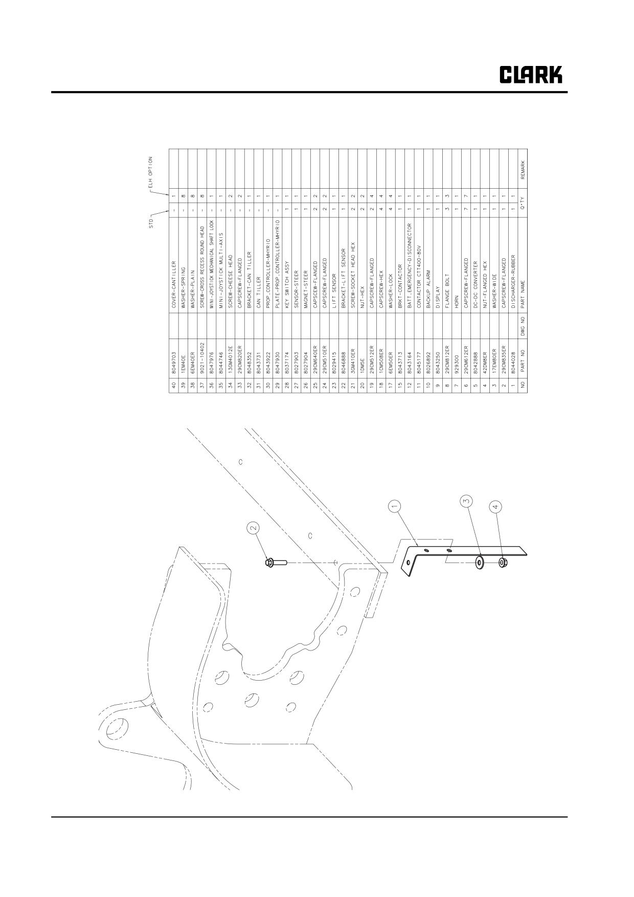
Group 13, Wiring, Switches, and Instruments
Electrical Components
13-3-2 • Wiring and Cables
SM 765, Nov ’06
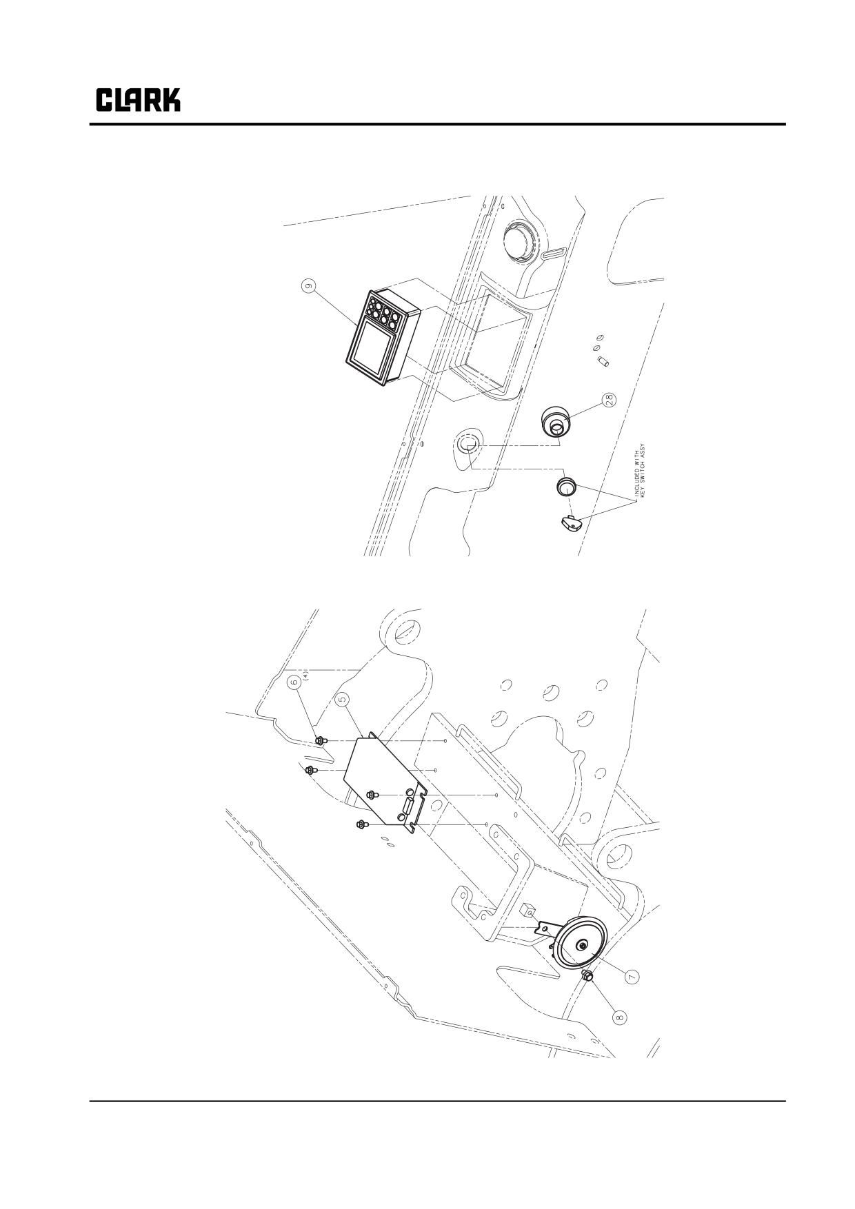
Group 13, Wiring, Switches, and Instruments
SM 765, Nov ’06
Wiring and Cables • 13-3-3
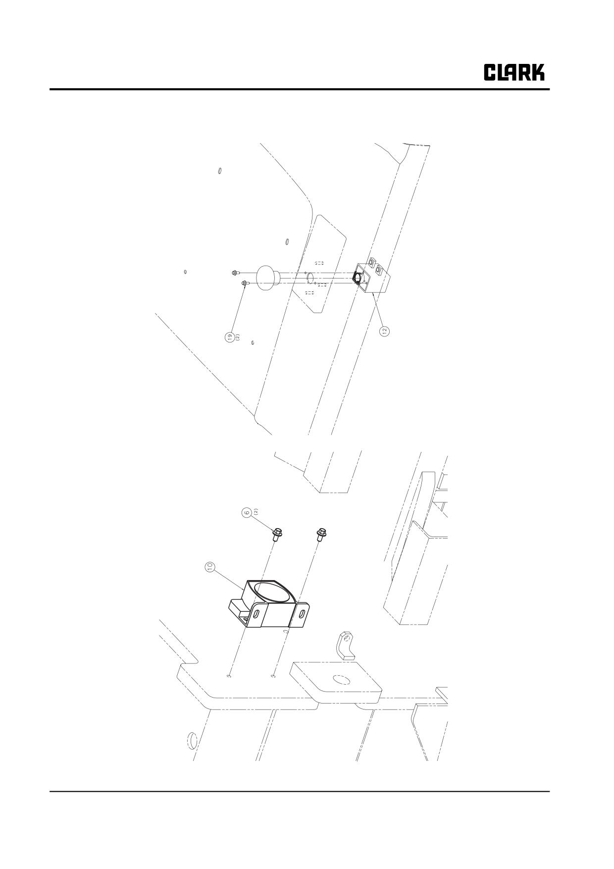
Group 13, Wiring, Switches, and Instruments
13-3-4 • Wiring and Cables
SM 765, Nov ’06
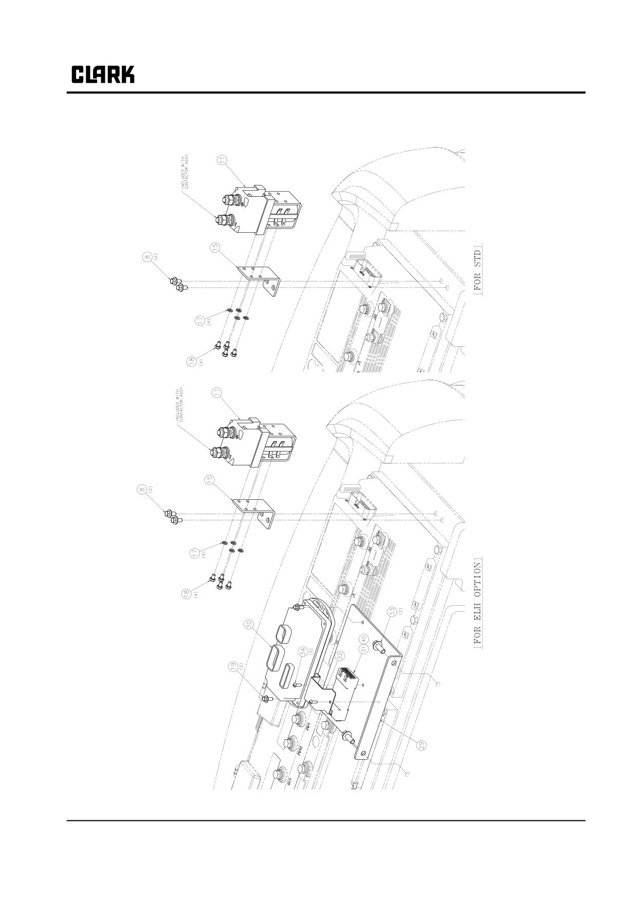
Group 13, Wiring, Switches, and Instruments
SM 765, Nov ’06
Wiring and Cables • 13-3-5
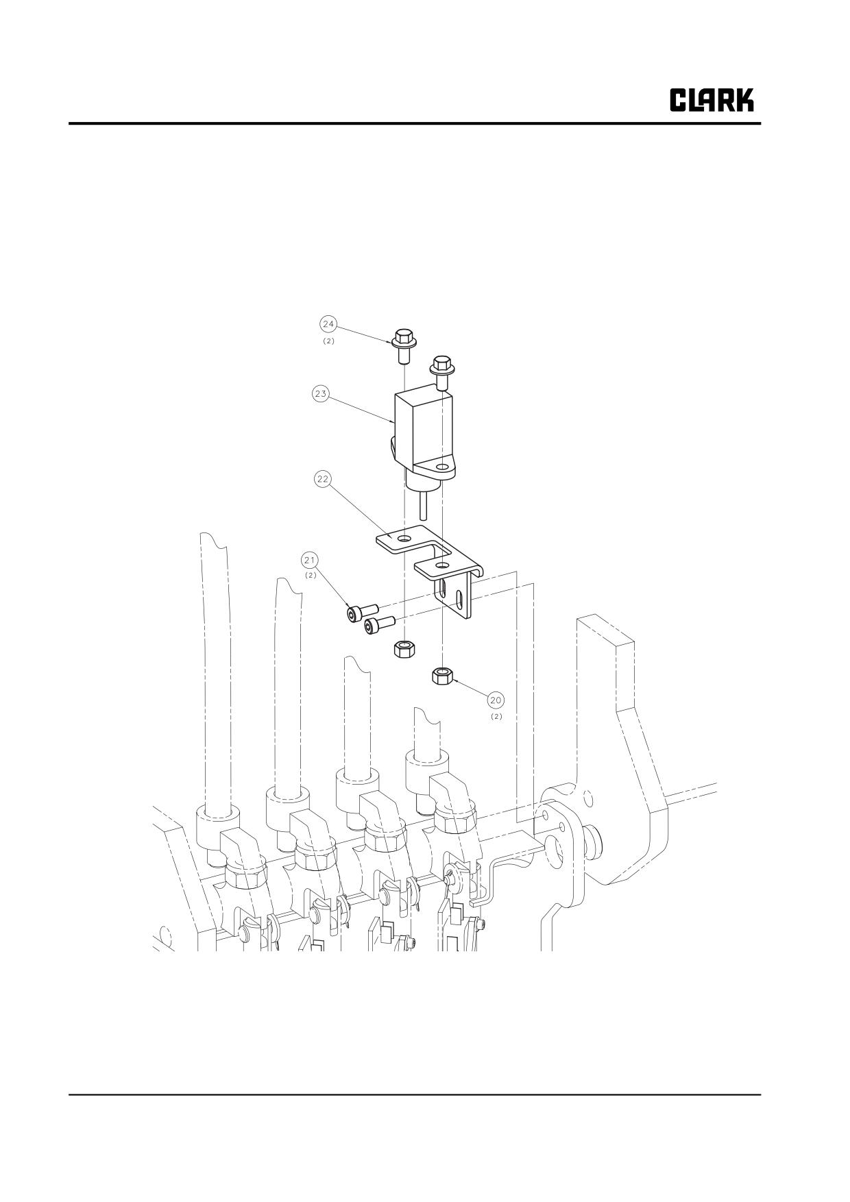
Group 13, Wiring, Switches, and Instruments
13-3-6 • Wiring and Cables
SM 765, Nov ’06
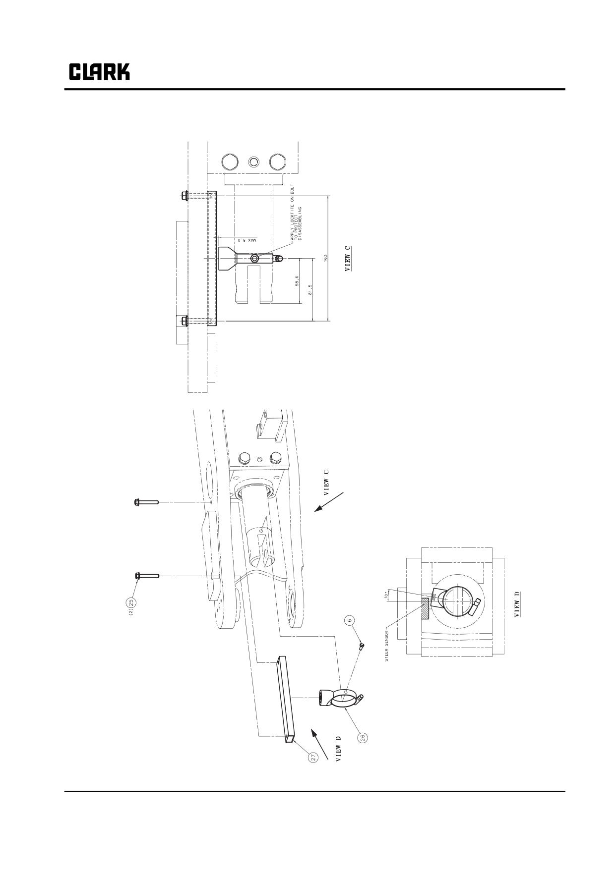
Group 13, Wiring, Switches, and Instruments
SM 765, Nov ’06
Wiring and Cables • 13-3-7
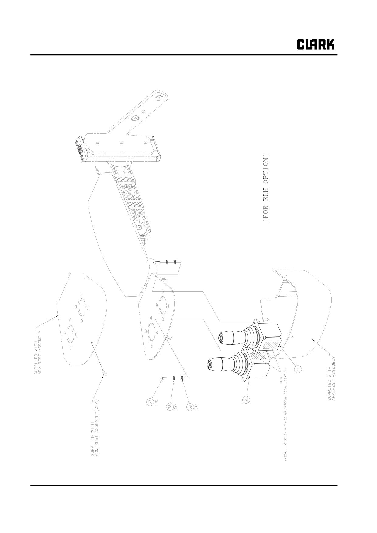
Group 13, Wiring, Switches, and Instruments
13-3-8 • Wiring and Cables
SM 765, Nov ’06
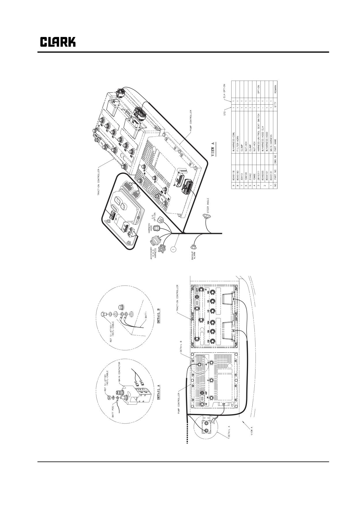
Group 13, Wiring, Switches, and Instruments
Main Harness
SM 765, Nov ’06
Wiring and Cables • 13-3-9
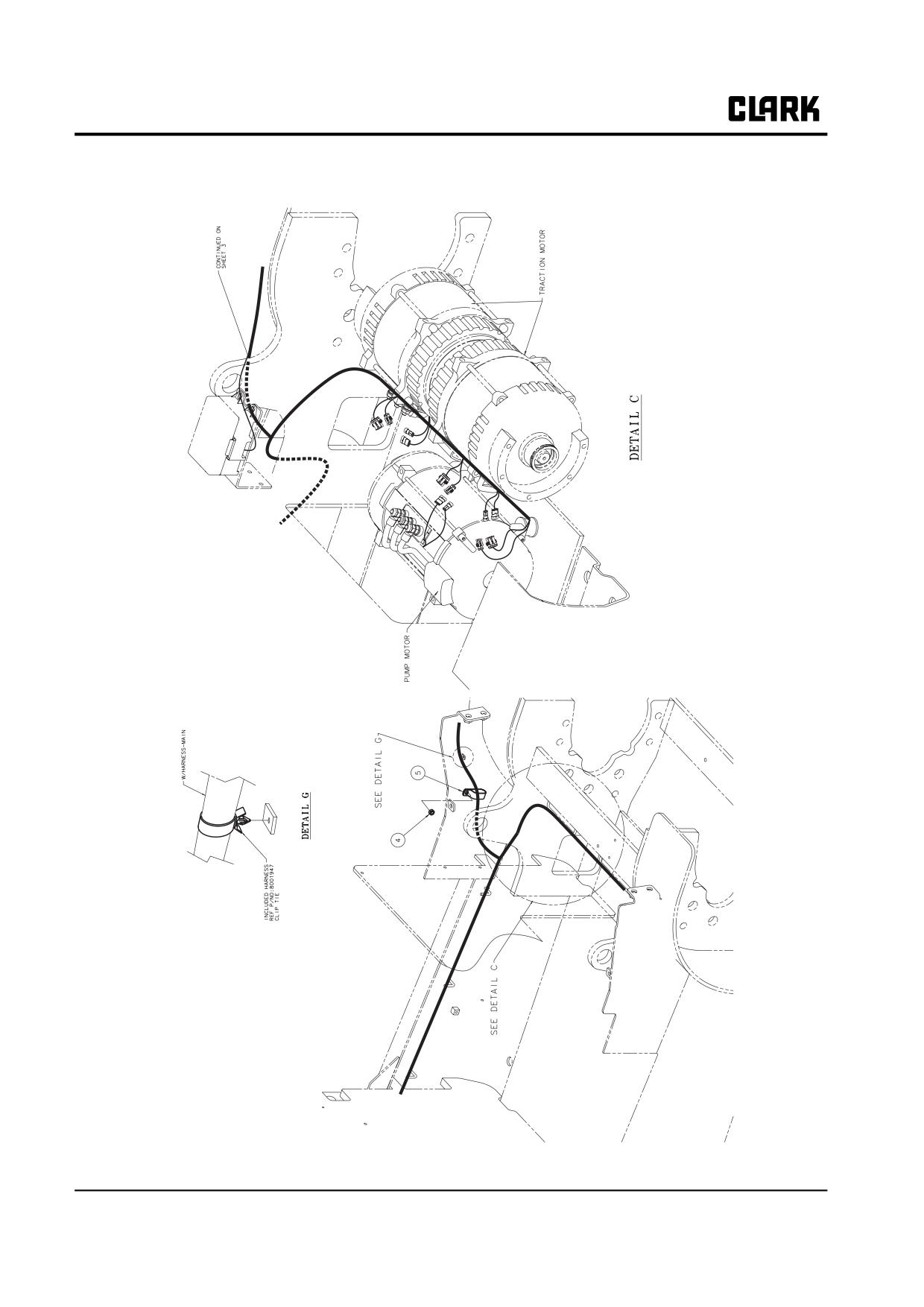
Group 13, Wiring, Switches, and Instruments
13-3-10 • Wiring and Cables
SM 765, Nov ’06
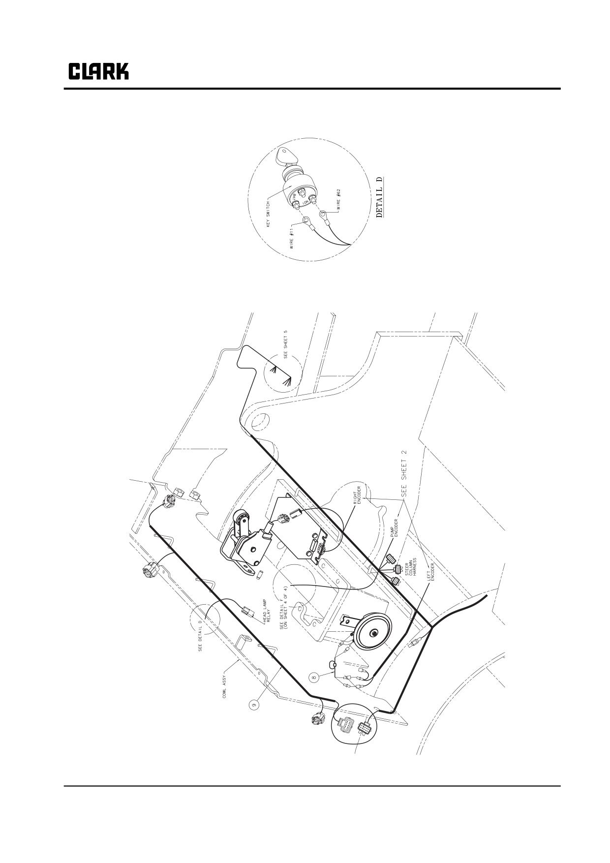
Group 13, Wiring, Switches, and Instruments
SM 765, Nov ’06
Wiring and Cables • 13-3-11
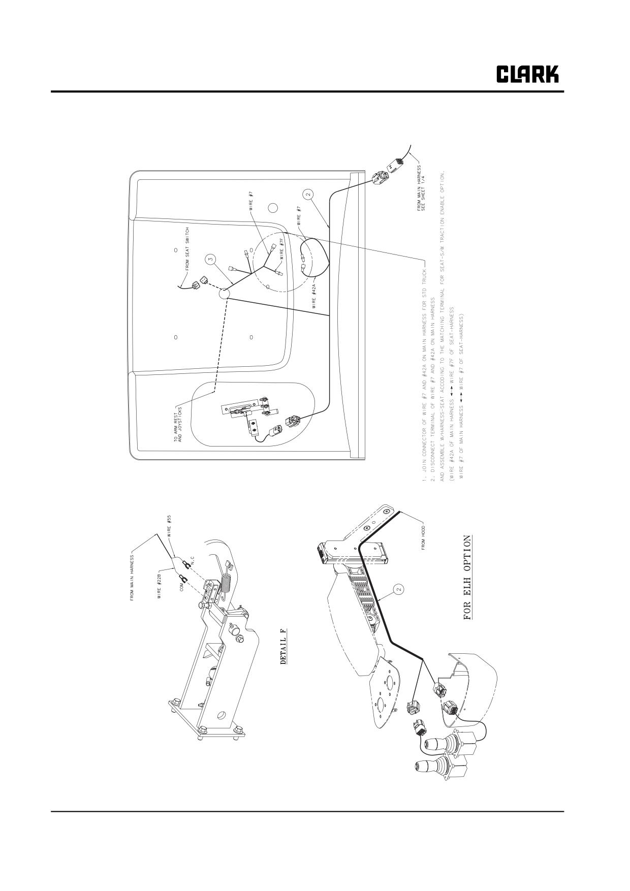
Group 13, Wiring, Switches, and Instruments
13-3-12 • Wiring and Cables
SM 765, Nov ’06
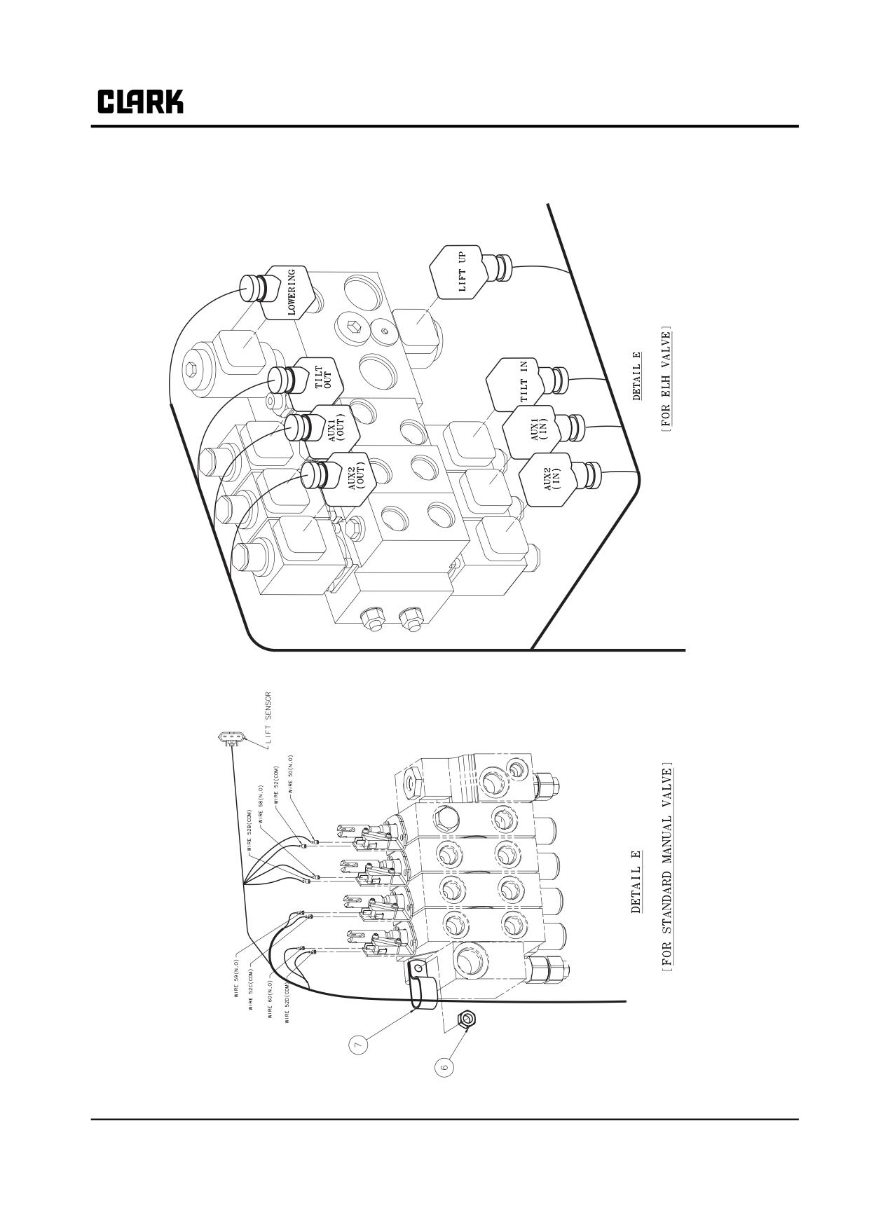
Group 13, Wiring, Switches, and Instruments
SM 765, Nov ’06
Wiring and Cables • 13-3-13
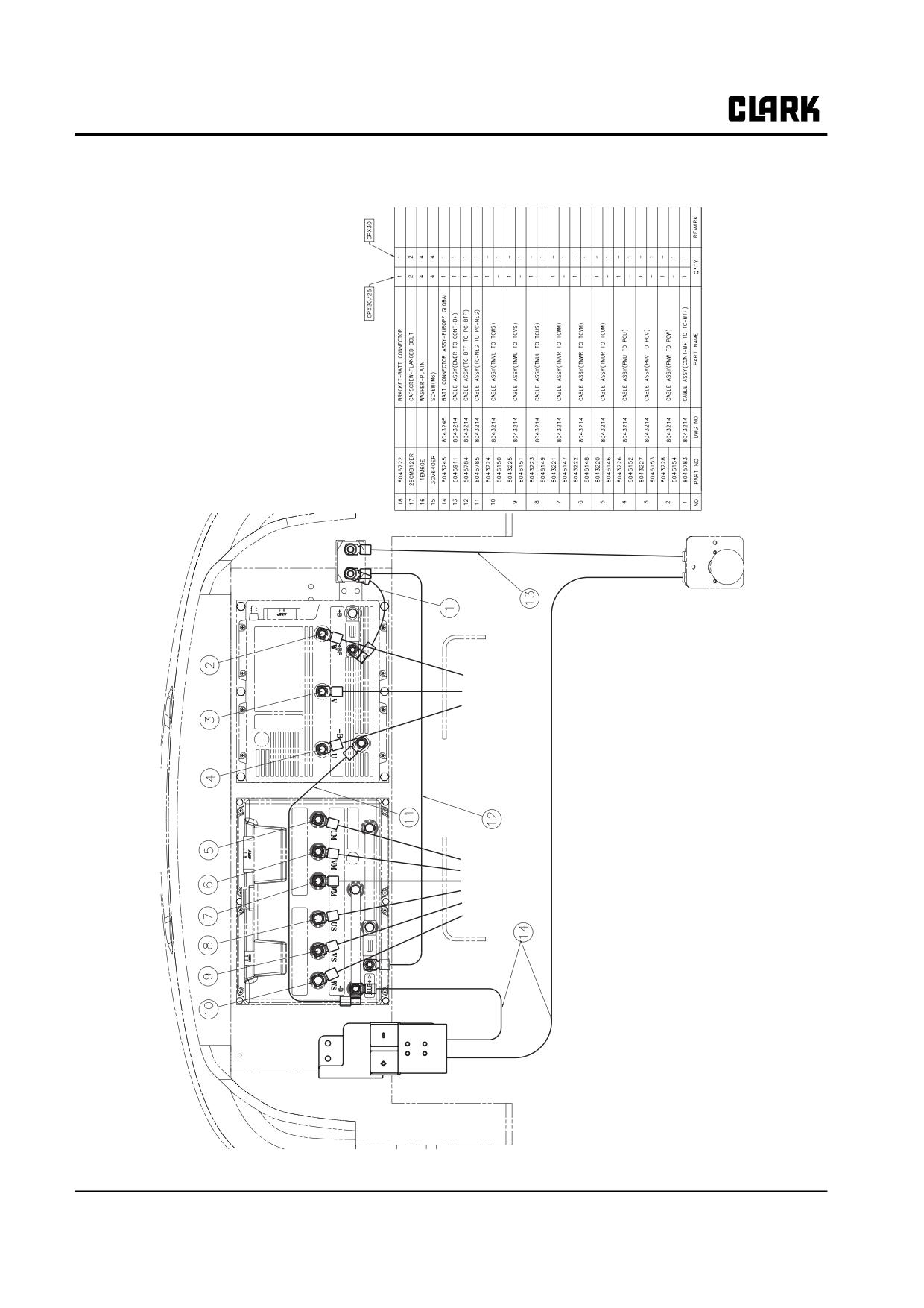
Group 13, Wiring, Switches, and Instruments
Cables
13-3-14 • Wiring and Cables
SM 765, Nov ’06
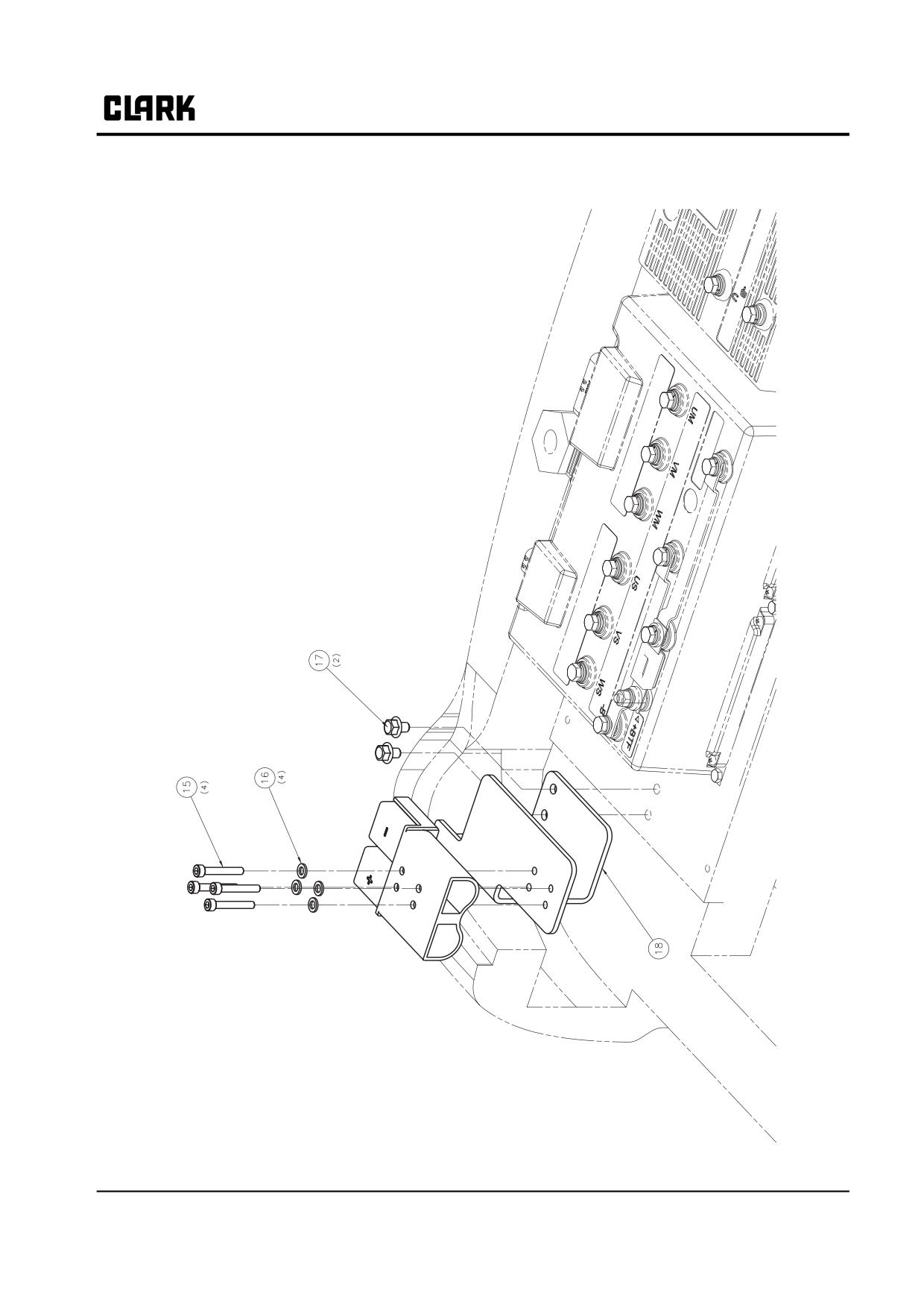
Group 13, Wiring, Switches, and Instruments
SM 765, Nov ’06
Wiring and Cables • 13-3-15
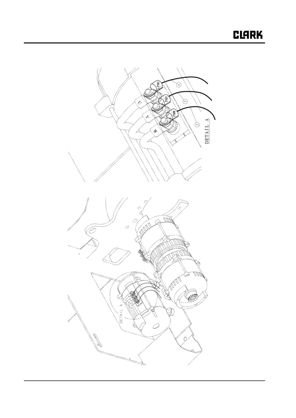
Group 13, Wiring, Switches, and Instruments
13-3-16 • Wiring and Cables
SM 765, Nov ’06
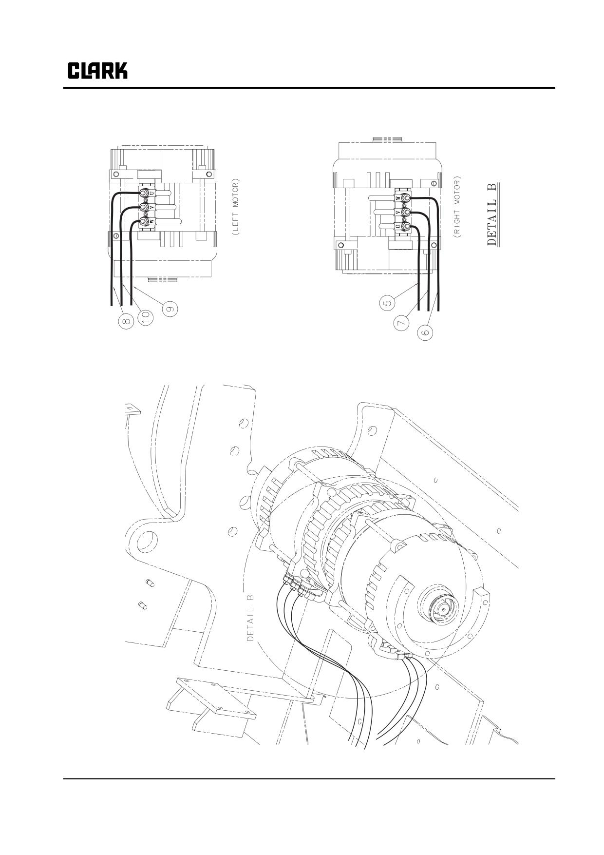
Group 13, Wiring, Switches, and Instruments
SM 765, Nov ’06
Wiring and Cables • 13-3-17
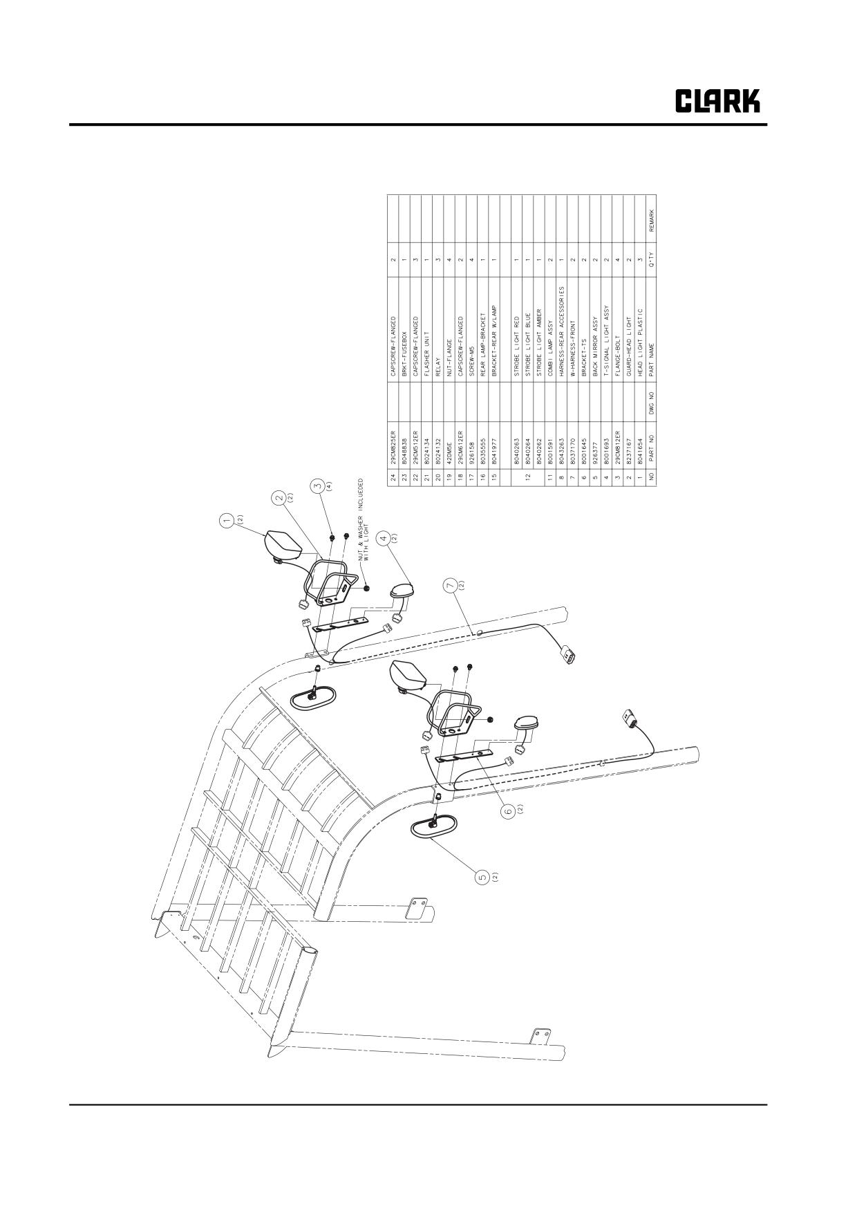
Group 13, Wiring, Switches, and Instruments
Accessory Harness and Components
13-3-18 • Wiring and Cables
SM 765, Nov ’06
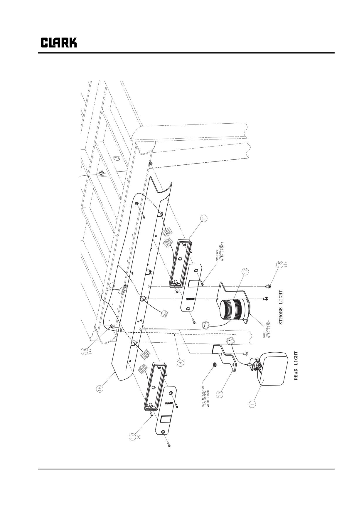
Group 13, Wiring, Switches, and Instruments
SM 765, Nov ’06
Wiring and Cables • 13-3-19
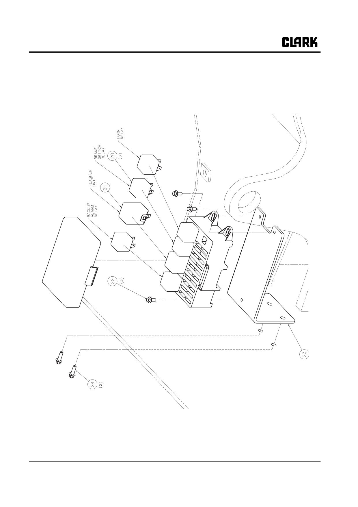
Group 13, Wiring, Switches, and Instruments
13-3-20 • Wiring and Cables
SM 765, Nov ’06
Group 13, Wiring, Switches, and Instruments
Section 4
Switches and Sensors
Accelerator Control Switch
2
Description
2
Adjustment
2
Program Adjustment
3
Brake Switches
3
Service Brake Switch Description
3
Service Brake Switch Adjustment
3
Parking Brake Switch Description
4
Parking Brake Switch Adjustment
4
Parking Brake Operation
4
Seat Switch
5
Lift and Tilt Pump Switches
5
Description
5
Switch Adjustment
5
Lift Pot Adjustment
6
Program Adjustment
6
SM 765, Sep ’06
Switches and Sensors • 13-4-1
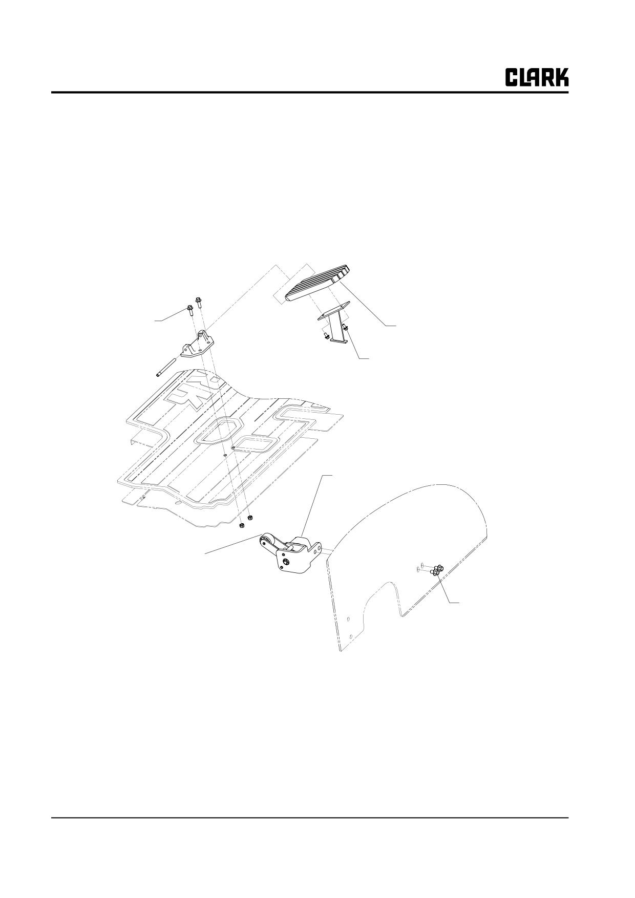
Group 13, Wiring, Switches, and Instruments
Accelerator Control Switch
Description
trical pulses to the motor, which in turn will supply more
power to the drive train.
The accelerator control is operated by the accelerator foot
An internal spring returns the control to start position. The
pedal to send a signal for power demand to the control.
accelerator is an integral unit and is not serviceable. Open-
At the start, the accelerator control is stroked (by the
ing of the unit will void the warranty.
action of the accelerator pedal), and in turn sends a signal
to the motor control, requesting it to produce longer elec-
A
Torque:
8-10 N.m
(71-88 in-lb)
Accelerator
Pedal
C
Torque:
5-6 N.m
(44-53 in-lb)
Accelerator
Control Switch
Roller
B
Torque
20-25 N.m
(177-221 in-lb)
13-4-2 • Switches and Sensors
SM 765, Sep ’06
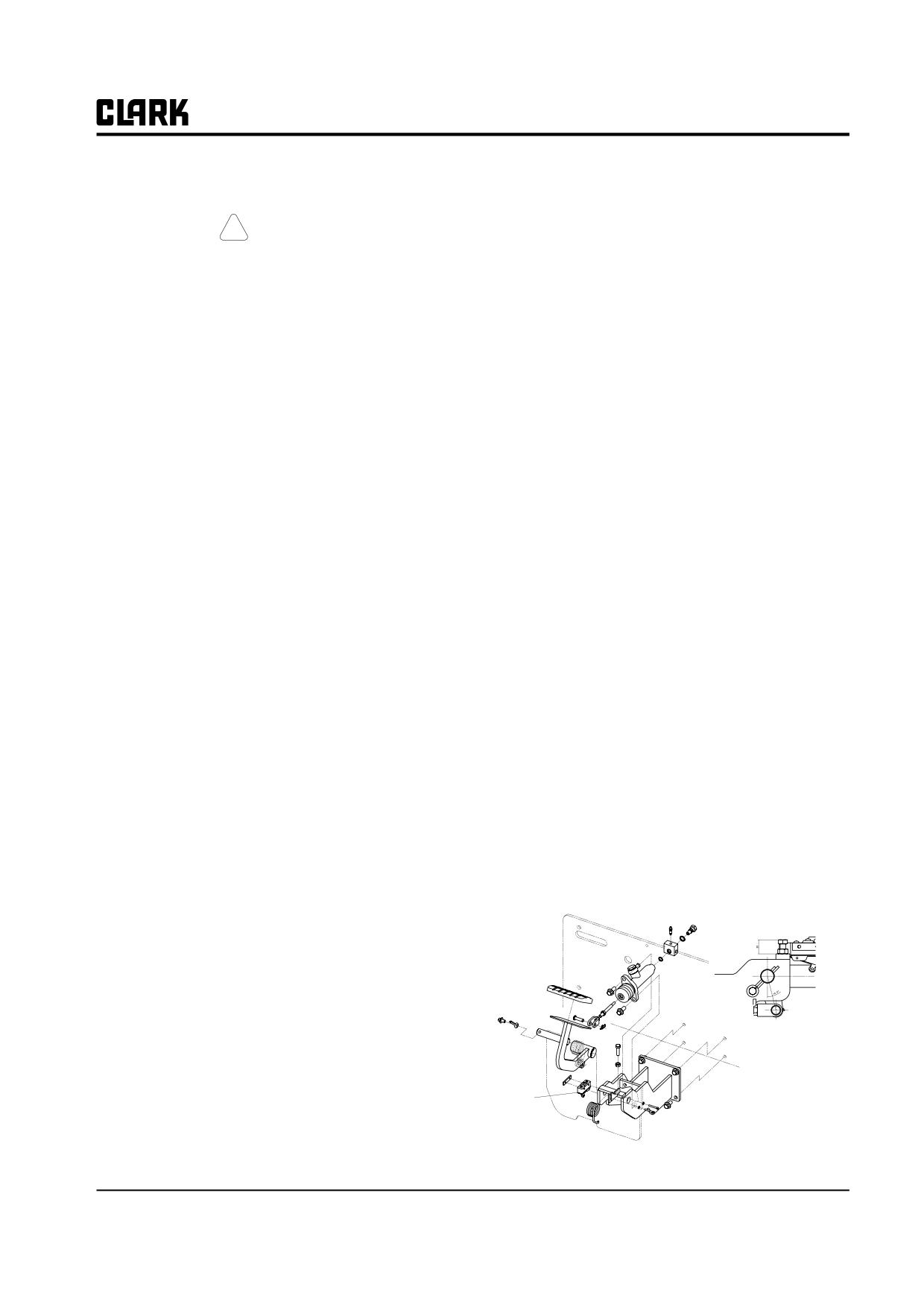
Group 13, Wiring, Switches, and Instruments
Program Adjustment
• Display will show software version
• Turn the key switch Off and remove the tester cord
from the control
! CAUTION
• Plug the dash display harness into the "B" plug of
Before any adjustments are done, safely jack
the control
up the truck, block the drive wheels off the
• Lower truck to the ground and test drive truck
floor and disconnect the battery.
Use the following method to program the accelerator con-
Brake Switches
trol to the contol panel with the handset:
(Detailed handset operation instructions are in Group 19.)
Service Brake Switch Description
•
Disconnect the dash display harness from the con-
The foot brake switch is on the brake link end, under the
trol panel
flow plate. The switch operates when it is released by the
•
Plug handset into plug "B" of the control
brake pedal lever during braking. Depressing or releasing
•
Plug in the battery
the switch operates a set of contacts that alternate from
•
Turn the key switch On
open to closed to activate the Pedal Braking function of
the control. This function uses the motor to help bring the
•
Handset will go through startup and display soft-
truck to a controlled stop.
ware version
•
Press the “ENTER” button
Service Brake Switch Adjustment
•
Display will read "MAIN MENU' "PARAMETER
CHANGE".
Adjust the switch so that it “clicks” just before the end of
•
Press the “ROLL UP” button five times
pedal “freeplay” (the lag between pressing the brake and
operating the master cylinder, covered in Group
23).
•
Display will read "MAIN MENU" “PROGRAM
Adjust switch as follows.
VACC”
•
Press the "ENTER" button
1. Turn key switch OFF.
•
Display will read "VACC SETTINGS"
2. Make sure freeplay is properly adjusted as described
•
Press the "ENTER” button
in Group 23.
•
Display will read "MIN VACC MAX"
3. Loosen brake switch mounting screws.
•
Move the directional lever to Forward position
4. Rotate switch against pedal until switch trips. (A
•
Depress the accelerator pedal to the floor and than
click can be heard.) Tighten mounting screws.
release slowly
5. Check operation of switch by depressing brake pedal.
•
Move the directional lever to the Reverse position
Switch should actuate just before the end of freeplay
•
Depress the accelerator pedal to the floor and than
(at which time you feel resistance in the pedal caused
release slowly
by the master cylinder beginning to operate.)
•
Press the "ENTER" button
•
Press the “OUT” button
•
Display will read "ARE YOU SURE"
"YES=ENTER" "NO=OUT"
•
Press "ENTER" button (this stores the value for
MIN and MAX accelerator voltage)
Capscrew height
•
Display will show new settings
control
•
Press the “OUT” button
•
Display will read "MAIN MENU" “PROGRAM
Brake
VACC”
Switch
•
Press "OUT button
SM 765, Sep ’06
Switches and Sensors • 13-4-3
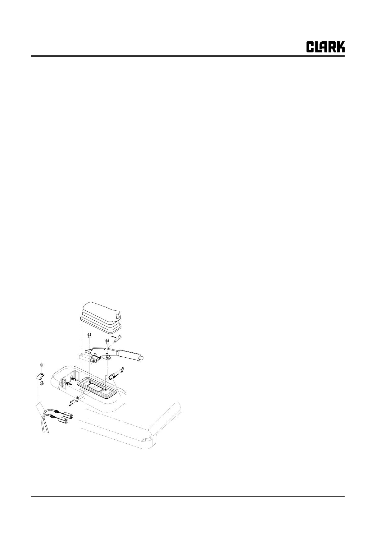
Group 13, Wiring, Switches, and Instruments
Parking Brake Switch Description
Parking Brake Operation
The parking brake switch is mounted to the hood under of
The operator applies the parking brake by pull up on a
parking brake assembly. The brake handle center pin
parking brake, which is then held by a ratchet. The pull-
depresses the switch when the hand lever is not applied.
ing up the brake lever tensions cables connected to a brake
This depressing of the switch closes the contacts.
shoe at each brake assembly, thereby applying the brakes.
The operator releases the parking brake by push down on
When the parking brake is applied, it releases the switch,
a Parking lever. Return spring returns the lever and
allowing the contacts to return their normally open posi-
cable to the off position. The lever also operates the park-
tion. This open circuit signals the controller to disable the
ing brake interlock switch and the parking brake indicator
drive motors.
light switch.
IMPORTANT
The switch must cut electrical current to the
drive motor before the brakes apply. Other-
wise, excessive lining wear will result and the
drive motor will overheat.
Parking Brake Switch Adjustment
1. Turn key switch OFF.
2. Loosen parking brake switch mounting screws.
3. Adjust position of switch so that there is contact with
the center pin and the switch actuates (clicks) just as
the parking brake lever is fully released.
4. Tighten mounting screws.
5. Check operation of switch before truck is returned to
service.
Parking Brake Switch
13-4-4 • Switches and Sensors
SM 765, Sep ’06
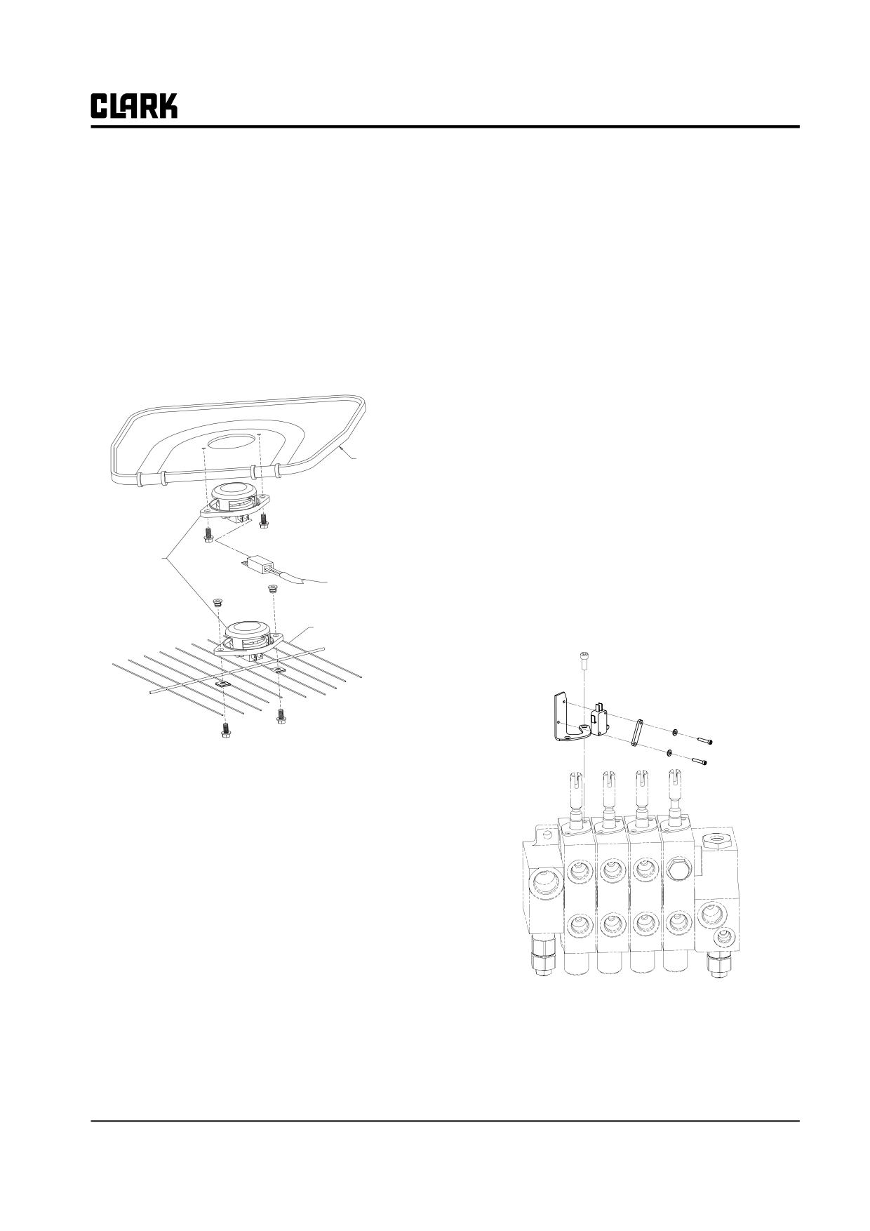
Group 13, Wiring, Switches, and Instruments
Seat Switch
Lift and Tilt Pump Switches
The GEX trucks are equipped with a seat switch that sig-
nals the control to cut the power when the operator
Description
leaves the seat.
The pump control switches are mounted on brackets at the
When the seat switch is open, a -01 fault code will be dis-
valve spools and they are normally open. Movement of th
played on the dash display.
valve spools from the neutral position trips the switches
and closes their contacts. Current flow through the con-
There is a 1.5 second time delay built into the control to
tacts signals the pump controller to operate the pump
allow for momentary opening of the seat switch. If the
motor at the set speed for the selected function.
truck is operated over rough surfaces and the operator is
bounced, causing a momentary opening of the seat switch,
The lift lever activates a lift enable switch and also acti-
the truck will not shut down.
vates a Lift Pot. This potentiometer signals the pump con-
troller to run at an increasing speed proportional to the
rearward movement of the lever.
Azdel Seat pan
Switch Adjustment
1. Turn key switch to the OFF position.
SUSPENSION SEAT
2. Loosen switch mounting screws.
3. Adjust switch to activate after spool moves from neu-
Seat Switch
tral.
Wire harness
4. Tighten mounting screws.
5. Check operation of switch before truck is returned to
Seat Flexolater
service.
STATIC SEAT
SM 765, Sep ’06
Switches and Sensors • 13-4-5
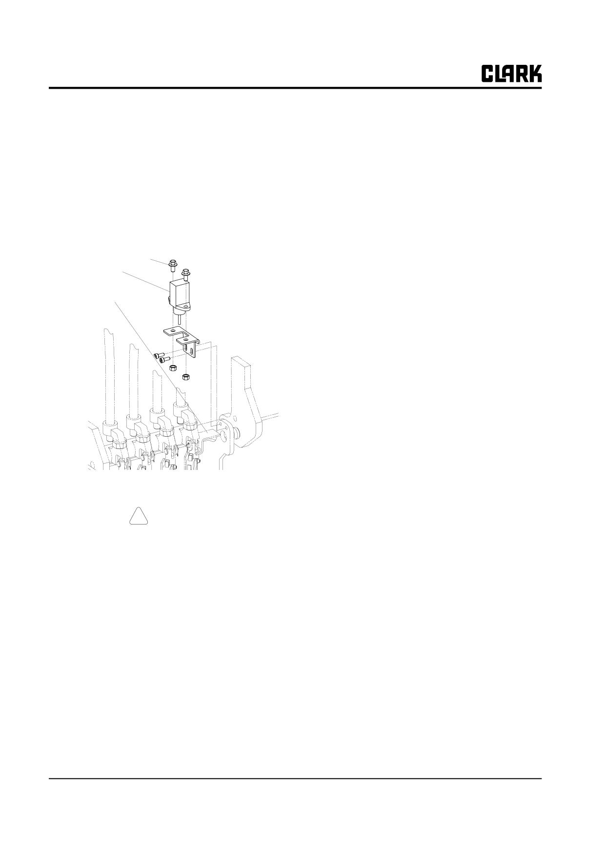
Group 13, Wiring, Switches, and Instruments
Lift Pot Adjustment
•
Display will read "CONFIG MENU' "SET
MODEL"
1. Insure that the flag of the actuator is properly posi-
•
Press "ENTER" button
tioned on the flat of the large nut.
•
Display will read "CONNECTED TO 3"
2. Tighten the lock nut against the bottom of the actua-
•
Press "PARAM SET UP" button two (2) times
tor.
•
Display will read "CONNECTED TO 5"
3. Loosen the capscrews on the switch mounting
•
Press "OUT" button
bracket and adjust the Pot to the point that it just
•
Display will read "ARE YOU SURE"
touches the actuator plate. Insure that the Pot is paral-
"YES=ENTER" "NO=OUT"
lel with the lift linkage.
Pot mounting screw
•
Press "ENTER" button (this stores the connected
to value)
Lift sensor
•
Display will read "CONFIG MENU" “CON-
NECTED TO”
Actuator
•
Press "OUT" button
•
Display will read Software Version for Pump Con-
trol
•
Press the “ENTER” button
•
Display will read "MAIN MENU' "PARAMETER
CHANGE".
•
Press the “ROLL UP” button five times
•
Display will read "MAIN MENU" “PROGRAM
VACC”
•
Press the "ENTER" button
•
Display will read "VACC SETTINGS"
•
Press the "ENTER” button
•
Display will read "MIN VACC MAX"
Program Adjustment
•
Move the lift lever to full raised position
•
Release the lift lever to the neutral position
! CAUTION
•
Press the “OUT” button
Before any adjustments are done, safely jack
•
Display will read "ARE YOU SURE"
up the truck, block the drive wheels off the
"YES=ENTER" "NO=OUT"
floor and disconnect the battery.
•
Press "ENTER" button (this stores the value for
MIN and MAX lift potentiometer voltage)
Use the following method to program the Lift Potentiome-
ter to the control panel with the handset:
•
Display will show new settings
•
Press the “OUT” button
(Detailed handset operation instructions are in Group 19.)
•
Display will read "MAIN MENU" “PROGRAM
• Disconnect the dash display harness from the con-
VACC”
trol panel
•
Press "OUT button
• Plug handset into plug "B" of the control
•
Display will show software version
• Plug in the battery
•
Turn the key switch Off and remove the tester cord
• Turn the key switch On
from the control
• Handset will go through startup and display soft-
•
Plug the dash display harness into the "B" plug of
ware version
the control
• Press both the "ROLL UP" and "PARAM SET UP"
•
Lower truck to the ground and test drive truck
buttons (top outside buttons) simultaneously.
13-4-6 • Switches and Sensors
SM 765, Sep ’06
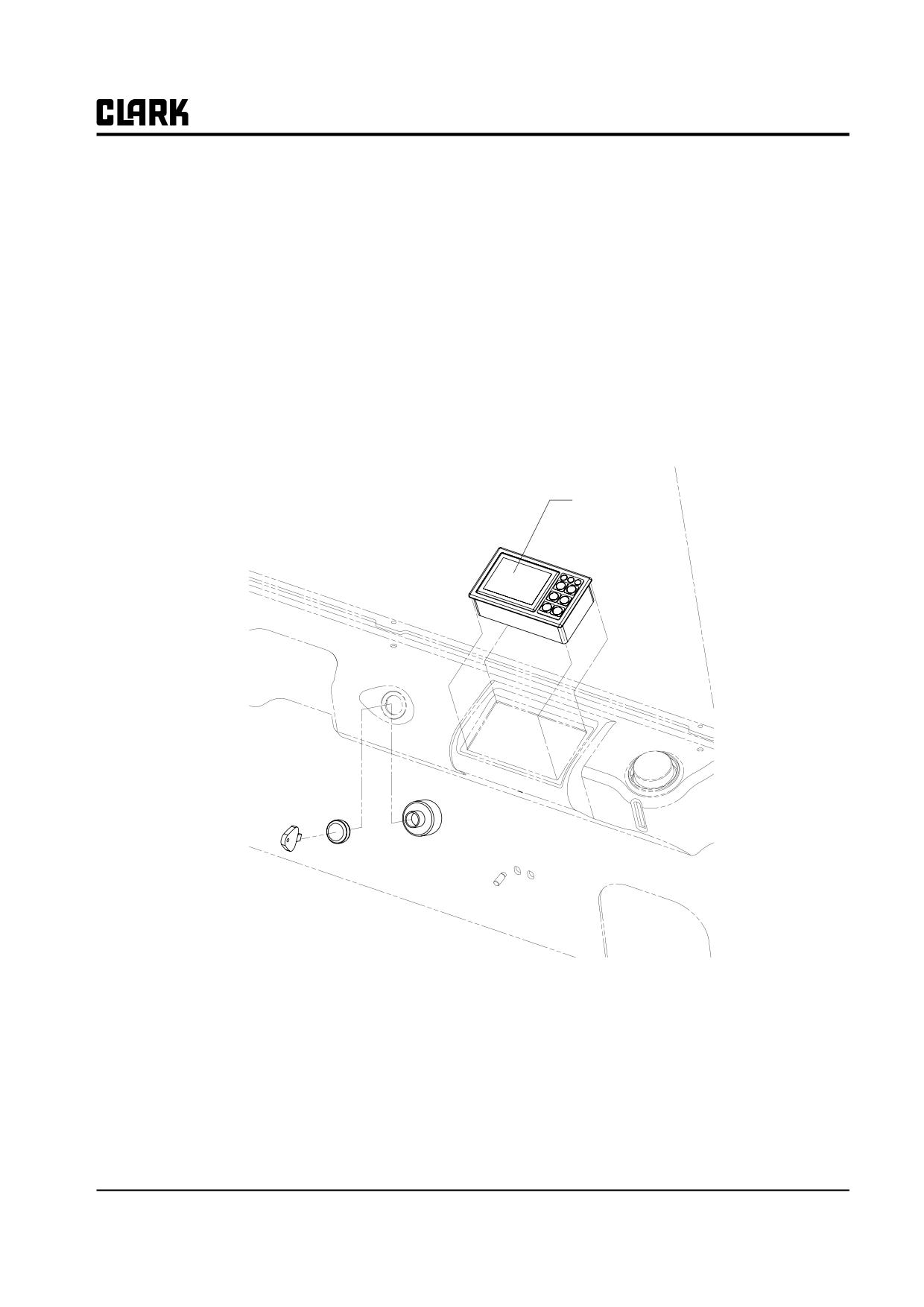
Group 13, Wiring, Switches, and Instruments
Section 5
Instrument Panel
Dash Display
SM 765, Sep ’06
Instrument Panel • 13-5-1
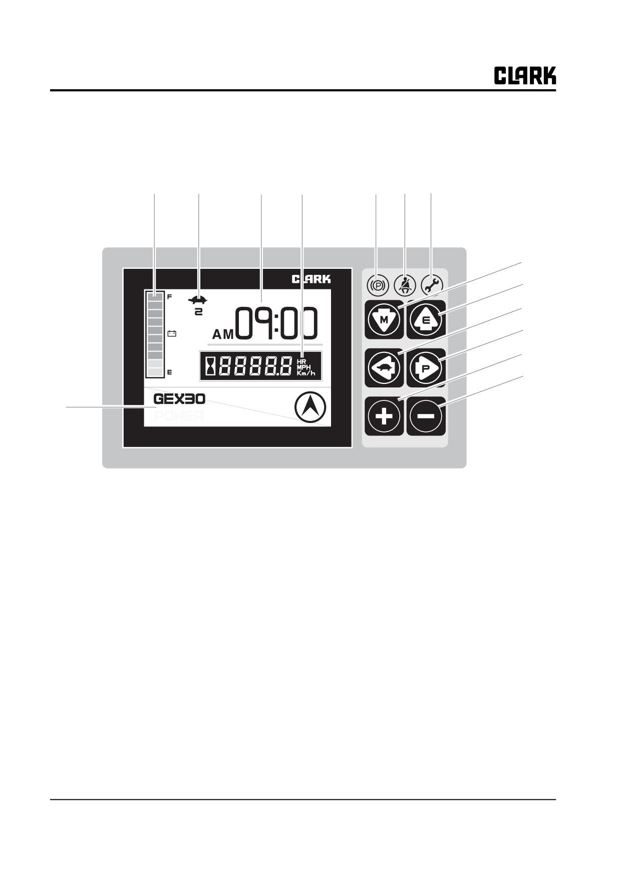
Group 13, Wiring, Switches, and Instruments
Dash Display
The Dash Display provides the operator with an easily understandable,
visual feedback of the status of the truck and its system components..
1
2
3
4
6
7
8
9
10
05/8/
10 [WED]
11
12
13
14
5
1. Fuel level Indication
8. Error LED
2. Slow-speed icon (Turtle shaped)
9. Down arrow button (Mode button)
3. Date & Time
10. Up arrow button (Enter button)
4. Hourmeter & Speed
11. Left arrow button (Slow speed button)
5. Message display & Travel direction icon
12. Right arrow button (Power button)
6. Parking brake LED
13. Plus button
7. Seat belt LED
14. Minus button
13-5-2 • Instrument Panel
SM 765, Sep ’06
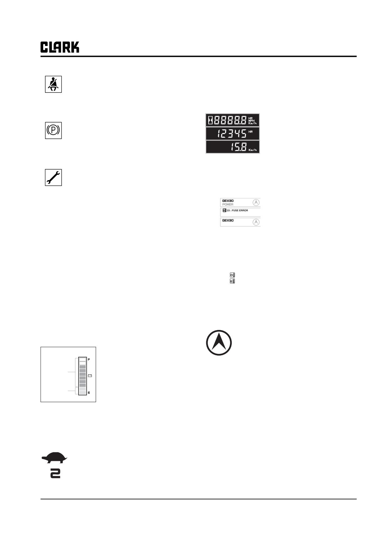
Group 13, Wiring, Switches, and Instruments
Seat Belt: At start up this symbol displays
max. speed. (In upper example, the limited max.
along with an audio alarm for 4 seconds. This
speed is 2km/h)
display reminds you to fasten your seat belt.
Hourmeter & Speed
• It displays the accumulated oper-
ating hour and traveling speed of
Parking Brake: The symbol is displayed and "-
truck.
255" status code appears on the numeric dis-
• When the traveling speed is less
play when parking brake is applied. Release
than 0.5km/h, it displays the accu-
parking brake to operate truck.
mulated operating hour.
• When the traveling speed is more
than 0.5km/h, it displays the traveling speed.
Service Status: The following 5 codes are usu-
ally operator fault codes, and can be corrected
by as explained in "Section 5, Operating Proce-
Message display
dures." If you see any other codes displayed,
The model name, POWER
the truck needs to be serviced.
Normal
selection, travel direction, warn-
Error
• -01 Seat Switch Open
ing and error message are dis-
Warning
played.
•-061, -065 ,-140,
-203, -207 Overheat of
BATTERY LOW
• In normal operating condition:
motor and controller (Restart after
Model name/POWER/Travel direction
cooling down)
•
When several messages are simultaneously dis-
• -66 Low Battery (truck will go into lift lock-
played, it will be displayed in the order of Error,
out when the dash display shows less
Warning and Normal condition.
than 15%)
• If many error conditions
• -77 Maintenance Hours (preset hour meter
23 : FUSE ERROR
are
simultaneously
reading indicating that it is time to have
56 : FET SHORT
occurred, the priority
2
the truck serviced. Truck will reduce the
Errors will be displayed.
top speed if desired)
(The priority means Error number)
• -79 Incorrect Start Up Sequence (SRO)
• -217, -245 Wrong set battery
Travel direction icon
• -255 Parking Brake Switch Open
• It displays the traveling direction or angle of
steering wheel..
Battery discharge indicator
• The direction icon rotates in 10 degrees.
It displays the battery discharge
(Total 36 icon)
condition of forklift truck.
The one bar indicates
10%
Blue color
Error icon
charging condition.
If the battery is charged more
When error occurs this icon is displayed to dis-
Red color
than 20% (8 bars or more), blue
tinguish the condition easily. When the error
LED is displayed, but it is less
message is displayed, this icon is simulta-
than 20% (2 bars or less), red
neously displayed.
LED is displayed. If it is less than 10% (1 bar), it will
flicker and buzzer sound.
Slow-speed indicator (Turtle shaped)
The traveling speed of truck is limited to
set speed.
The upper mark is slow speed operating
icon, and the figure shows the limited
SM 765, Sep ’06
Instrument Panel • 13-5-3
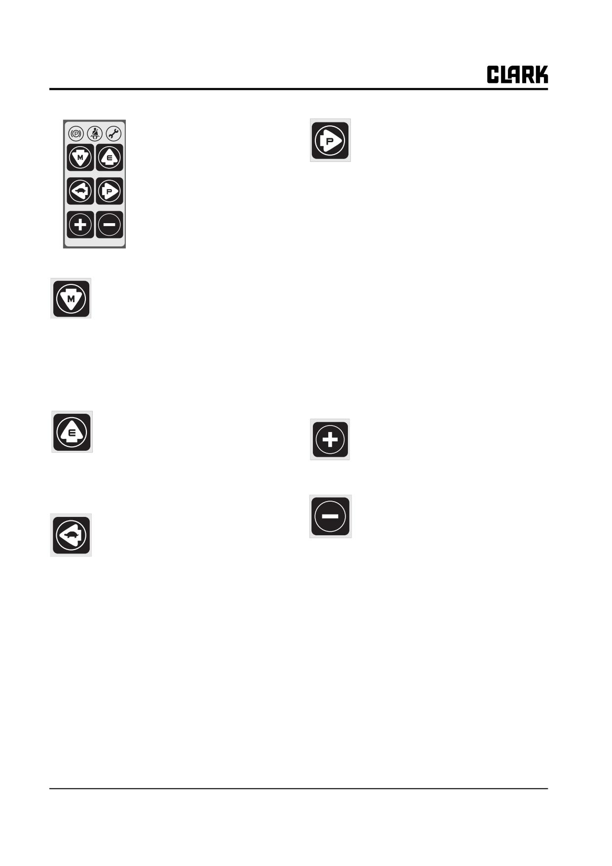
Group 13, Wiring, Switches, and Instruments
MODE SELECTION BUT-
Right arrow button (Power
TON.
selection button)
• 6 mode selection buttons are
1.Pressing this button, it will move to right
located on right side of LCD.
menu.
• Each button has specific function,
2.In normal operating condition, it will select/
and some have multiple functions.
release Power.
-Power mode is composed of 3 steps, and it
can be adjusted by use of "+/-" buttons. After
adjusting the speed, press "Enter" (Up arrow)
button to store it.
-Power mode
In the order of Economy
→ Normal →
Down arrow button (Mode but-
Power; Pressing "+" button to move right, and
ton)
"-" left.
1.Pressing this button in normal operating
•Economy: It is Slow speed mode to save the
condition, it will move to Menu mode.
battery consumption as minimizing the accel-
eration function.
2.Pressing it in Menu mode, it will move to
lower menu.
•Normal: It is normal operating mode, and
smooth acceleration can be done.
3.Pressing it in the lowest mode, there will be
•Power: Powerful acceleration is possible and
no change.
the work ability will be improved.
Up arrow button (Enter button)
Plus(+) button
1.Pressing this button, it will move to upper
Increase the data as set value in the cur-
menu.
rent Menu mode.
2.It will also take role of "Enter" button when
confirming the changed password or main
parameters.
Minus(-) button
Left arrow button (Slow speed
Decrease the data as set value in the cur-
button)
rent Menu mode.
1.Pressing this button, it will move to left
menu.
2.In normal operating condition, it will select/
release Slow speed.
-When pressing, the following figure will be
displayed and Slow speed selected.
-Press once more to release.
-The figure will be disappeared and Slow
speed released.
Chang of slow speed
Use "+/-" buttons to change the set speed
while the Slow speed is selected. After adjust-
ing the speed, press "Enter" (Up arrow) button
to store it.
The speed can be set from 2 km/h to 9km/h
with unit of 1km/h.
13-5-4 • Instrument Panel
SM 765, Sep ’06
GROUP 16 ELECTRICAL MOTORS
GROUP 16
ELECTRICAL MOTORS
Motor Specifications And Descriptions
Section 1
Drive Motor Overhaul
Section 2
Pump Motor Overhaul
Section 3
SM 765, Nov ’06
Group 16 ELECTRICAL MOTORS
NOTE :
Group 16 ELECTRICAL MOTORS
SM 765, Nov ’06