Parker 590+ series Frame 1, 2, 3, 4, 5, 6 & H. Product Manual (2012) - page 4
3-20 Installing the Drive
Power Connections continued
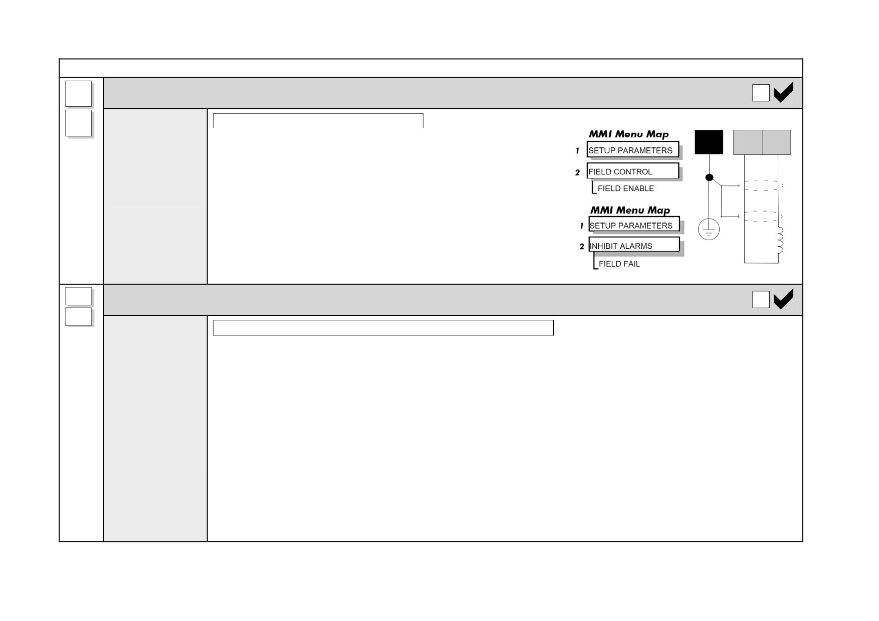
F-
Motor Field
Connect the
Frame 3: Terminals F- & F+ = D3 & D4
F+
motor field (-)
Connect the cable screen to the independent earth/ground point.
PE
F+
F-
to terminal F-,
If the motor has no field connections, is a permanent magnet motor,
and connect
star
or if the field is derived externally, you must either:
point
field (+) to
terminal F+.
disable the FIELD ENABLE parameter (Tag No. 170)
later during Set-up (disables the Field Fail alarm automatically)
or
+
disable the Field Fail alarm
Th1
Motor Thermistor
Th2
Connect the
Frames 3, 6 & H: Terminals Th1 & Th2 = THERM1 & THERM 2
motor
Terminals Th1 and Th2 must be linked if motor sensors are not fitted.
thermistor to
(Thermistor terminals for Frames 3, 6 & H are on the Control Door Board).
terminals Th1
and Th2
We recommend that you protect the dc motor against overtemperature by the use of temperature sensitive resistors
or switches in the field and interpole windings of the machine. When the motor is fitted with over-temperature
or
sensing devices, such as thermostats or PTC thermistors, these should be connected (in series) between terminals
link terminals
TH1 and TH2.
if sensors are
• Thermistors must have a combined working resistance of 750Ω or less, rising to 4kΩ at over-temperature.
not fitted.
These thermistors are classified by IEC34-II as Mark A.
• Temperature switches must be normally closed, and open at rated temperature.
The over temperature alarm will activate at 3kΩ. It is latched in software and must be reset by re-starting the Drive.
NOTE The motor temperature alarm (THERMOSTAT) cannot be inhibited in software.
Installing the Drive
3-21
Power Connections continued
These terminals must be used
FL1
External AC Field
on Frame 6 and Frame H drives
FL2
Connect the
Frame 3: Terminals FL1 & FL2 = D1 & D2
external field
(Not available on Frame 1 units)
supply to
Used if an external field supply is required to the controller for application reasons. The magnitude of this voltage is
terminals FL1
determined by the desired field voltage. The supply must be protected externally with suitable fuses.
and FL2.
IMPORTANT The connection of the controller and the external field supply must be consistent when
using an externally supplied field regulator. Always derive the 1phase, 50/60Hz supply
from the L1 (Red) and L2 (Yellow) phases of the main power supply, directly or indirectly
through a single-phase transformer, with the Red phase connected to terminal FL1 and the
Yellow phase to terminal FL2.
NOTE You must provide branch circuit and overload protection.
To change the drive from an internal to an external field type refer to "Motor Field Options", page 3-30.
L
Auxiliary Supply
Connect the
Frame 3: Terminals L & N = D8 & D7
N
control supply
Single phase, 110/240V ac, 50/60Hz.
to terminals L
(Live) and N
Note: The auxiliary supply chosen must equate to the contactor coil voltage used.
(Neutral).
IMPORTANT The auxiliary supply terminals must be connected directly to the incoming supply via a
fuse or circuit breaker. No series sequencing switches or contacts are permitted without
consultation from SSD Drives.
Use suitable external fuse protection: the steady state current absorbed by the controller is nominal, the external fuse
is determined chiefly by considering the contactor holding VA and the controller cooling fans. (Frame H fans are
powered separately).
Refer to Appendix E: “Technical Specifications” - Power Supply Fuses.
3-22 Installing the Drive
Control Connections
A1
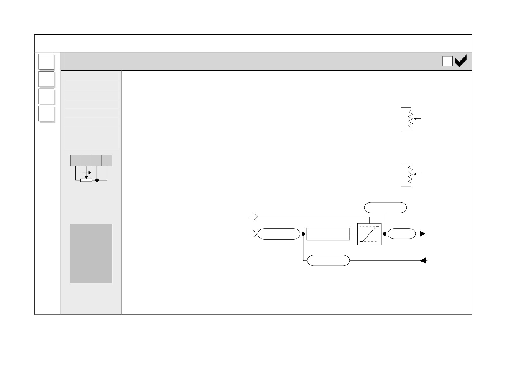
Ramp Speed Setpoint
Connect a 10k
Uni-directional Speed Setpoint
A4
potentiometer
This connection provides a Uni-Directional Speed Setpoint for non-reversing applications and the 2 Quadrant
between
controller (591+):
B3
+10V
terminals A1
Maximum forward speed setpoint (+100%)
=
Terminal B3, +10V input
B3
B4
and B3.
Ramp
Zero speed setpoint (0%)
=
Terminal B1, 0V input
A4
Input
Connect the
wiper to A4.
Thus, zero speed is at the left (anti-clockwise) position on the potentiometer.
A1
0V
Bi-directional Speed Setpoint
Alternatively, substitute A1 for terminal B4 to scale the input such that:
+10V
B4
A4
B3
A6
B3
Maximum forward speed setpoint (+100%)
=
Terminal B3, +10V input
Ramp
Maximum reverse speed setpoint (-100%)
=
Terminal B4, -10V input
A4
Input
10K
B4
Thus, zero speed demand is at the centre position on the potentiometer.
potentiometer
-10V
CURR. DMD
A6
Current Clamp
Speed
Speed Setpoint
A4
RAMP INPUT
SPEED LOOP
I LOOP
Demand
Controls
simplified view
I LIMIT
the speed
SPEED FBK
of the
motor
In both cases, the Current Limit is controlled via terminal A6 (ANIN5).
NOTE Terminals A1, B1 and C1 (Signal 0V) are the common reference points for all analog signals used
in the drive.
Installing the Drive
3-23
Control Connections continued
A6
Current Limit
Connect
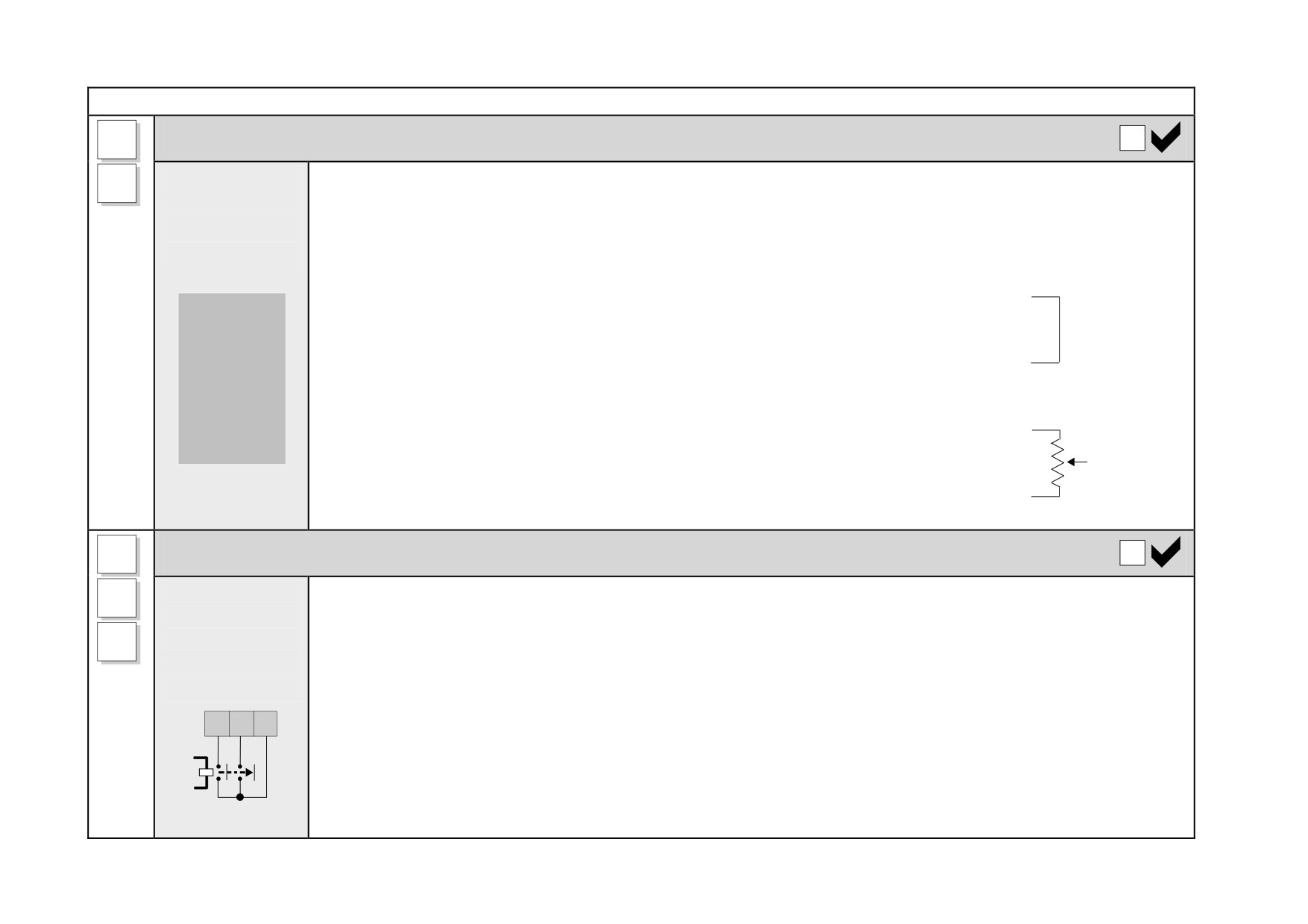
This connection provides control of the Positive and Negative Current Clamps and hence the Current Demand via
B3
terminal A6 to
terminal A6 (ANIN5). The "ANIN 5 (A6)" function block contains parameters to set up maximum/minimum values
B3.
for the analog input, and a scaling ratio.
Adjust the main current limit using the MAIN CURR. LIMIT parameter [Tag No. 15]. Refer to Appendix D:
"Programming" - CURRENT LOOP.
+10V
B3
Fixed Current Limit
Current
For normal operation of the main current limit, connect Terminal A6 (ANIN5) to
Limit
Terminal B3 (+10V reference) and set the CURR.LIMIT/SCALER parameter to 200%.
Controls
A6
This allows the MAIN CURR.LIMIT parameter to adjust the current limit between 0 and
the
Current
200% full load current.
Limit
available
+10V
motor
Variable Current Limit
B3
torque
If external control of the current demand is required, an additional 10K potentiometer
Current
A6
connected between Terminal B3 (+10V Ref) and Terminal B1(0V), with the wiper
Limit
connected to Terminal A6 (Analog I/P5) gives 0 to 200% of full load current provided
B1
that the MAIN CURR. LIMIT and CUR. LIMIT/SCALER parameters are set to 200%.
0V
B8
Program Stop/Coast Stop
These connections provide a Program Stop (B8), and a Coast Stop (B9).
Connect
B9
Refer to Chapter 4: "Operating the Drive" - Starting and Stopping Methods.
terminals B8
& B9 to C9 via
C9
The "Emergency Stop" relay (normally-open, delay on de-energisation) should not be part of the normal sequencing
an Emergency
system which is implemented via the Start contacts, but is a relay which can be operated in exceptional
Stop relay.
circumstances where human safety is of paramount importance.
B8
B9
C9
• Removing 24V from B9 opens the main contactor via the relay
• Removing 24V from B8 provides regenerative braking for 4 Quadrant DC590+ drives
E'
Stop
A regenerative drive can be stopped using a Normal Stop, a Program Stop, or an Emergency Stop. However, a
Relay
non-regenerative drive can only be made to stop faster than friction and loading will allow by Dynamic
PROG COAST
STOP STOP
Braking.
3-24 Installing the Drive
Control Connections continued
Enable
C5
Connect
Terminal C5 (Enable) must be connected to C9 (+24V) to allow the drive to run.
C9
terminal C5 to
Connection via a switch is useful to inhibit the drive without opening the main contactor, however, it is not a
C9.
safe mode of operation as the drive dc output is only reduced to zero. If the equipment controlled by the
drive is to be serviced, then this method should be avoided and the drive disabled and isolated.
It is important that more than one stop input (ENABLE C5, START/RUN C3, COAST STOP B9, PROG
STOP B8) is always used to ensure stopping of the drive under single fault conditions .
Start/Run
C3
Connect
When the single contact between C3 and C9 is closed the drive will run provided that:
C9
terminal C3 to
• B8 & B9 are TRUE (+24V) - see "Emergency Stop" above
C9 via a
• C5 is TRUE (+24V) - see "Enable" above
switch.
When the single contact between C3 and C9 is opened the drive will decelerate the motor to zero speed at a rate
determined by the STOP TIME parameter’s value and the MAIN CURR. LIMIT value. Refer to Appendix D:
“Programming” - STOP RATES for further details.
NOTE If Enable C5 is opened during a Normal Stop sequence, the drive is disabled, the contactor opens,
and the drive will Coast To Stop.
Jog/Slack
C4
• If the drive is stationary this switch provides a Jog facility.
Connect
C9
• If the drive is running, this switch provides a Take-Up Slack facility.
terminal C4 to
For other user-definable operating modes, refer to Appendix D: "Programming" - JOG/SLACK for further details.
C9 via a
switch or
pushbutton.
Installing the Drive
3-25
Control Connections continued
External Trip
C1
Terminals C1 and C2 must be linked if an External Trip interlock is not required.
Connect
C2
terminal C1 to
This input terminal provides an external trip facility to any normally-closed trip switch , e.g. for vent fan overload
C2, or link
protection.
terminals if
not required.
C1
Drive Healthy
This is one of three digital output terminals that provide a +24V dc output signal under certain conditions. They
Connect
B6
allow for the connection of relays which, in conjunction with the Enable, Start/Run and Emergency Stop relay, can
terminal C1 to
be used to enhance the safe starting and stopping of the controller.
B6 via a lamp
(for example).
The drive is "healthy" (TRUE) if there is no Start command.
These are configurable outputs and can be used as required in the control system design, i.e. cubicle door lamps,
connection to a suitable PLC.
B5
Digital Outputs
There are three digital output terminals that provide a +24V dc output signal under certain conditions. They allow
User
B6
for the connection of relays which, in conjunction with the Enable, Start/Run and Emergency Stop relay, can be
connection to
used to enhance the safe starting and stopping of the controller.
external
B7
equipment.
These are configurable outputs and can be used as required in the control system design, i.e. cubicle door lamps,
connection to a suitable PLC.
The default actions are:
• B5 = Zero Speed Detected
• B6 = Drive Healthy
• B7 = Drive Ready
Refer to Appendix E: "Technical Specifications" - Terminal Information - Control Board, also Chapter 6: "The
Keypad" - DIAGNOSTICS.
3-26 Installing the Drive
Control Connections continued
A2
Direct Speed Setpoints
Connect your
A3
Speed Setpoint No. 1 (A2)
external
This input is configurable Terminal A2 (Analog Input 1) is a direct speed demand by-passing the "Setpoint Ramp
setpoint(s) to
C8
Generator", and should be used if direct control is required.
terminal A2
and/or A3.
Speed Setpoint No. 2 / Current Demand (A3)
This input is not configurable. Terminal A3 (Analog Input 2) is a dual function terminal (either "Speed Setpoint No.
2" or "Current Demand") as selected by mode switch control "Current Demand Isolate", Terminal C8. As a speed
setpoint, it can be used in the same way as Terminal A2.
If more than one speed setpoint is used, they are additive. Also refer back to A4, Ramp Speed Setpoint, page 3-22.
A5
Auxiliary Current Clamp (-ve)
Connect
Used to allow separate control of positive and negative Main Current Clamps, for example, in Winder applications.
B4
terminal A5 to
Enable bipolar current clamps by providing 24V at terminal C6. Terminal A5 (ANIN4) is an Auxiliary Current
B4 to provide
C6
Clamp (-ve), 0 to -10V.
-10V, or
C9
supply
NOTE If driven positive, it will form a current demand.
externally.
The "ANIN 4 (A5)" function block contains parameters to set up maximum/minimum values for the analog input,
Connect
and a scaling ratio.
terminal C6 to
With 24V at terminal C6, Terminal A6 (ANIN 5) acts only as the Auxiliary Current Clamp (+ve), 0 to +10V.
C9 to enable
bipolar
current
clamps.
Installing the Drive
3-27
Control Connections continued
A7
Analog Outputs
User
These are configurable outputs and can be used as required in the control system design, i.e. connection to a meter,
A8
connection to
for cascading to another drive.
external
• Terminal A7, Analog Output 1 provides a Speed Feedback value, -10V to +10V
equipment.
• Terminal A8, Analog Output 2 provides a Total Speed Setpoint value, -10V to +10V
The "ANOUT1" and "ANOUT2" function blocks contain parameters to configure the values.
A9
Current Meter Output
User
This connection is for a Current Meter.
connection to
The "ARMATURE I (A9)" parameter is used to select either unipolar or bipolar output. Refer to Appendix D:
external
"Programming" - CALIBRATION.
equipment.
This ouput is not configurable. It is driven directly by hardware.
C6
Digital Inputs
User
These configurable 24V dc digital inputs are used to control the drive.
C7
connections to
The default configurations are:
the drive.
C8
• C6 : Current Clamp Select (see
A5 and
A6 )
• C7 : Ramp Hold
• C8 : Current Demand Isolate (see
A3 )
Refer to Appendix E: "Technical Specifications" - Terminal Information - Control Board, also Appendix D:
"Programming" - DIGITAL INPUTS.
3-28 Installing the Drive
Control Connections continued
G1
Analog Tachometer
Refer to Optional Equipment, page 3-53, for further information.
User
G2
connection to
An Analog Tachometer is connected to the Drive using a screened twisted pair cable throughout its entire length to
external
provide speed feedback via the Tacho Calibration Option Board. This provides facility for an AC or DC tachometer.
G3
equipment.
The screen is grounded or earthed only at the drive end, any other grounding arrangement may cause problems.
G4
Fit the Tacho
• Terminals G1 & G2 are for AC tacho connections.
Calibration
• Terminals G3 & G4 are for DC tacho connections.
Option Board
NOTE The speed loop is set-up for an analog tacho by the SPEED FBK SELECT parameter in the
to the Drive.
SPEED LOOP function block. Select ANALOG TACH for this parameter.
This provides
If an AC tachogenerator is used the output is rectified to produce the dc feedback to the speed loop.
terminals G1
Consequently, the controller can only be used with a positive setpoint.
to G4.
Refer to Chapter 4: “Operating the Drive” for set-up information.
F1
Microtach
Refer to Optional Equipment, page 3-53, for further information.
User
C1
connection to
The Parker SSD Drives MICROTACH is available in two versions:
external
C9
z
5701 Plastic Fibre Microtach
z
5901 Glass Fibre Microtach
equipment.
A Microtach can be connected to provide speed feedback via the Microtach Option Board using the international
Fit the
standard “ST” fibre optic system.
Microtach
F1 is the fibre optic receiver input socket. Terminals C9 (+24V dc) and C1 (0V) are used to provide the supply and
Option Board
return respectively.
to the Drive.
NOTE The speed loop is set-up for the Microtach by the SPEED FBK SELECT parameter in the SPEED
This provides
LOOP function block. Select ENCODER for this parameter.
the fibre optic
terminal F1.
The maximum Microtach frequency is 50kHz, thus with a standard 1000 lines per revolution Microtach the motor
speed cannot exceed 3000 rpm.
For specification and connection information refer to Parker SSD Drives or the appropriate Technical Manual.
Installing the Drive
3-29
Control Connections continued
E1
Wire-Ended Encoder
Refer to Optional Equipment, page 3-53, for further information.
User
E2
connection to
The wire-ended encoder is connected to the Drive using a screened cable throughout its entire length to provide
external
speed feedback.
E3
equipment.
Terminals E1 (0V) and E2 (+24V dc) are the return and supply respectively.
E4
Fit the
NOTE The speed loop is set-up for the Encoder by the SPEED FBK SELECT parameter in the SPEED
Encoder
LOOP function block. Select ENCODER for this parameter.
E5
Option Board
The maximum allowable encoder frequency is 100kHz, thus with a standard 1000 lines per revolution encoder the
to the Drive.
E6
motor speed cannot exceed 6000 rpm.
This provides
For specification and connection information refer to Parker SSD Drives or the appropriate Technical Manual.
terminals E1
to E6.
H1
Technology Box Option
User
The Technology Box Option allows drives to be linked together to form a network. We can supply Options for most
H2
connection to
protocols. Refer to Appendix D: "Programming" - TEC OPTION for information about Technology Box Option
external
types.
H3
equipment.
For detailed information, refer to the appropriate Technical Manual supplied with the Technology Box.
H4
Fit the
Technology
H5
Box Option to
the Drive.
H6
This provides
terminals H1
to H6.
3-30 Installing the Drive
Motor Field Options
WARNING
Isolate the drive before converting to internal/external supply.
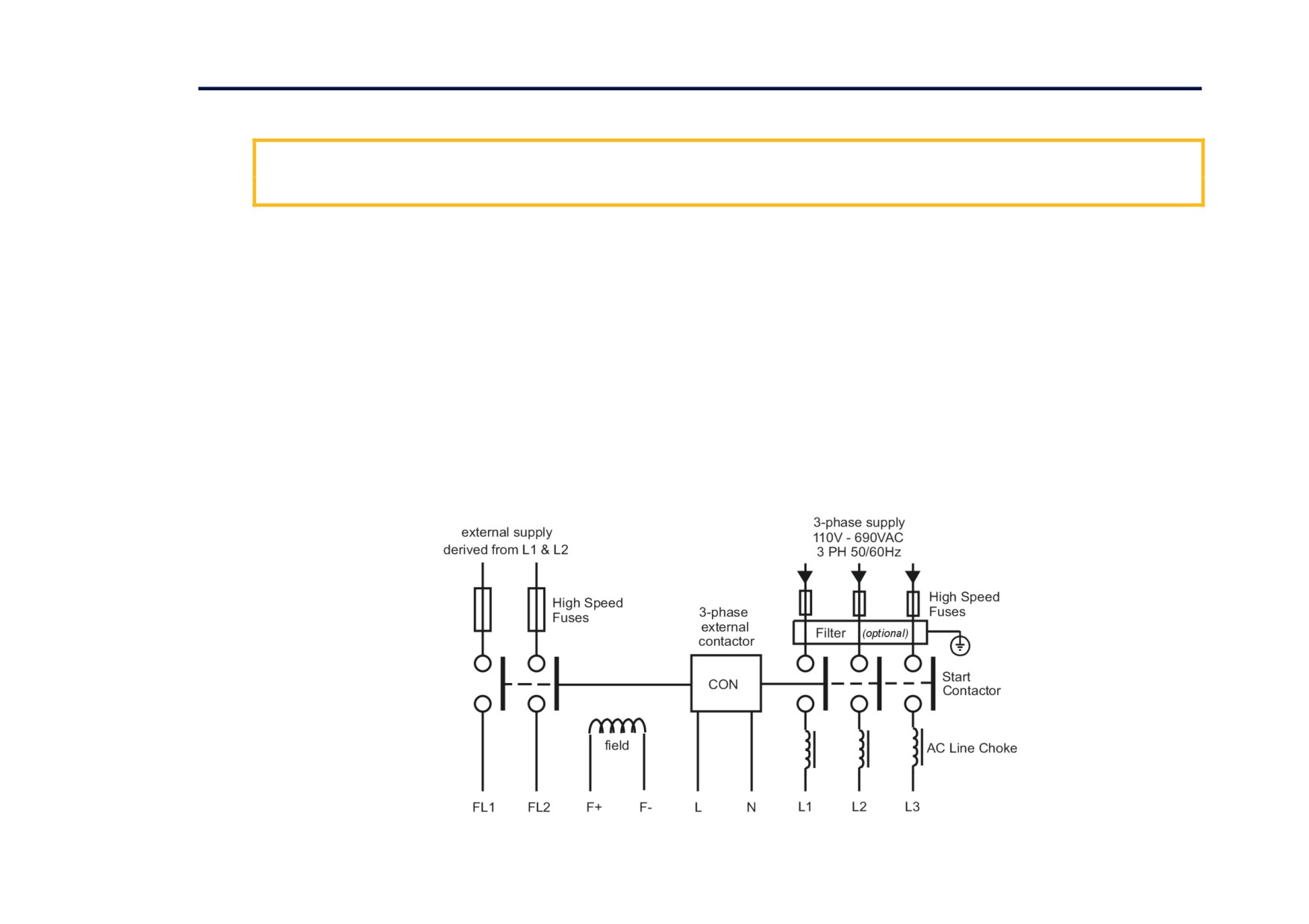
The FIELD CONTROL function block controls the motor field. The FLD CTRL MODE parameter allows you to select either Voltage or Current
Control mode.
• In Voltage Control mode, the FLD. VOLTS RATIO parameter is used to scale the motor field output voltage as a percentage of the input supply
voltage.
• In Current Control mode, the SETPOINT parameter is used to set an absolute motor field output current, expressed as a percentage of the calibrated
field current (IF CAL).
Internal/External Supply (Frames 2, 3, 4 & 5)
NOTE The Frame 1 unit allows only an internal motor field supply. The Frame 6 and Frame H units always require an
external motor field supply. For information about the following terminal/power boards refer to Appendix E:
“Technical Specifications” - Terminal Information (Power Board).
The internal motor field is more widely used, however, there is provision on the unit for an external motor field supply to be connected (perhaps for
where the field voltage is greater than the input voltage and therefore not attainable, or where the motor field is switched separately for convenience).
Figure 3- 12 Typical connection diagram
Installing the Drive
3-31
Terminal Board - PCB Reference 470330 (Frame 2)
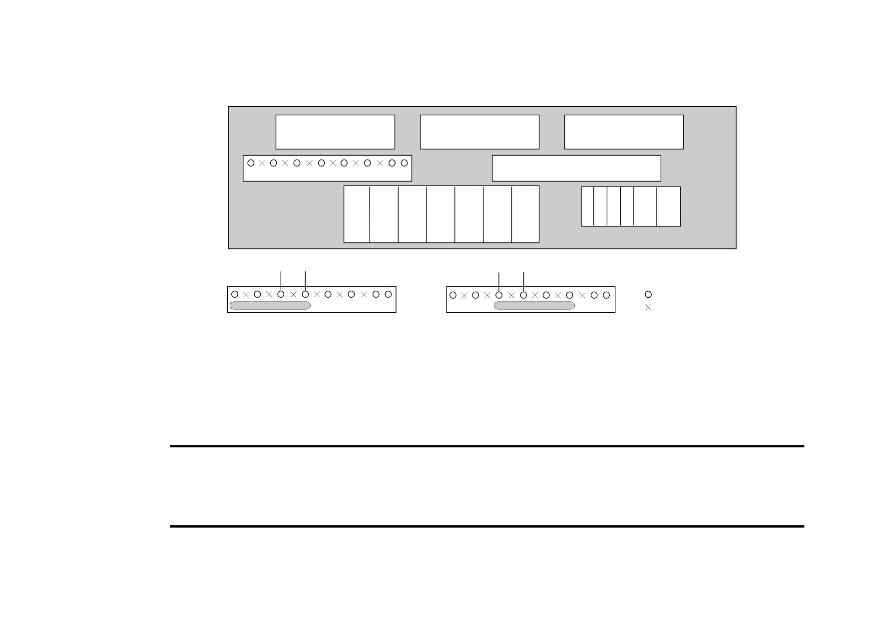
The position of the jumper selects the board to use either an internal or external motor field.
PLG1 to Power Board
PLG2 to Power Board
PLG3 to Power Board
Motor Vent Fan Circuit Breaker
External Field Selector Plug
L
N
3
4
TH1
TH2
FL1
FL2
F+
F-
M1
M2
M3
Terminal Board
Field Bridge
Field Bridge
FL1
FL2
L1
L2
FL1
FL2
L1
L2
fitted pin
non-fitted pin
Jumper selecting external field
Jumper selecting internal field
Internal Motor Field (default for this board)
Terminals F+ and F-, the motor field outputs, are energised when the 3-phase supply is connected to L1/L2/L3. Terminals FL1 and FL2 are not
required. The internal motor field supply is fused by 10A fuses, FS5 & FS6.
External Motor Field Connections
Terminals FL1 and FL2 can be used for external ac supply connection for the Motor Field Supply. You should provide suitably rated external, fast-
acting semi-conductor fusing, to a maximum of 10A.
Caution
When using an external ac input it is important to have the correct phase relationship on the terminals. The supply must be
derived from L1 (Red) and L2 (Yellow) phases directly or indirectly through a single-phase transformer.
L1 must be connected to FL1, and L2 connected to FL2.
The external field supply can now be connected and power restored to the drive.
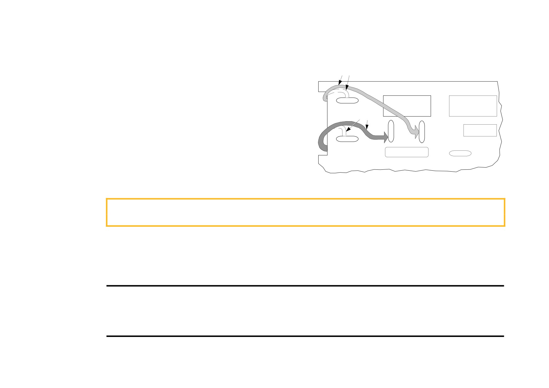
3-32 Installing the Drive
Power Board - PCB Reference 385851 (Frame 3)
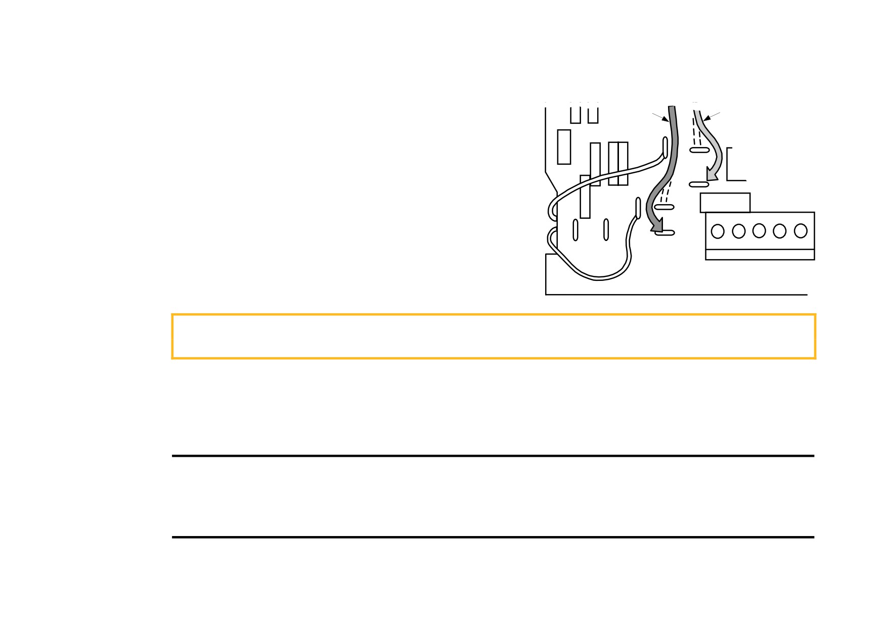
This power board (printed with the above number) can be altered for use with either an internal or external motor field supply:
Internal Motor Field (default for this board)
Yellow
POWER BOARD AH385851
Terminals D3 and D4, the motor field outputs, are energised when the 3-
phase supply to L1/L2/L3 is energised and the internal motor field is used.
D1
D2
D3
D4
Terminals D1 and D2 are not energised. The internal motor field supply is
fused by the 10A fuses, FS2 & FS3.
F8
Red
External Motor Field Connections
Terminals D1 and D2 on the Power Board can be used for an external ac
F19
F18
supply connection for the Motor Field Supply.
A simple re-wiring procedure disconnects the internal motor field supply and
F16
prepares terminals D1 and D2 for the external ac supply connection.
You should provide suitably rated external, fast-acting semi-conductor fusing,
to a maximum of 10A.
Re-Wiring Procedure
WARNING
Isolate all power to the drive.
1. Loosen the control board fixing screws (2 off) and position the control board to allow access to the power board.
2. Remove the red link from the Faston connector “F16” on the left-hand side of the board and connect it to staging post “F19”, located below
terminal D1.
3. Remove the yellow link wire from the Faston connector “F8” on the left-hand side of the board and connect it to staging post “F18”, located below
terminal D2.
Caution
When using an external ac input it is important to have the correct phase relationship on the terminals. The supply must be
derived from L1 (Red) and L2 (Yellow) phases directly or indirectly through a single phase transformer.
L1 must be connected to D1, and L2 connected to D2.
The external field supply can now be connected and power restored to the drive.
Installing the Drive
3-33
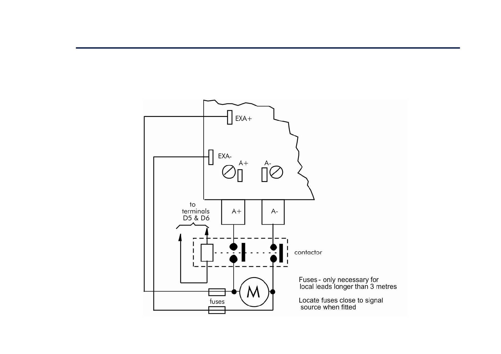
Power Board - PCB Reference 466701 (Frames 4 & 5)
This power board (printed with the above number) can be altered for use with either an internal or
external motor field supply:
red
yellow
Internal Motor Field (default for this board)
Terminals F+ and F-, the motor field outputs, are energised when the 3-phase supply
to L1/L2/L3 is energised and the internal motor field is used. Terminals FL1 and
F4
FL2 are not energised. The internal motor field supply is fused by the 30A fuses FS1
F5
and FS2.
F6
EX L2
External Motor Field Connections
Terminals FL1 and FL2 on the Power Board can be used for an external ac supply
F1
F2
connection for the Motor Field Supply.
F13
F14
F3
EX L1
A simple re-wiring procedure disconnects the internal field supply and prepares
terminals FL1 and FL2 for the external ac supply connection.
EX A- EX A+
You should provide suitably rated external, fast-acting semi-conductor fusing, to a
FL1 FL2
F+
F-
maximum of 30A.
Re-Wiring Procedure
WARNING
Isolate all power to the drive.
1. Loosen the control board fixing screws (2 off) and position the control board to allow access to the power board.
2. Remove the red link from the Faston connector “F2” and connect it to the staging post “F3” nearby (EX L1).
3. Remove the yellow link wire from the Faston connector “F5” and connect it to the staging post “F6” nearby (EX L2).
Caution
When using an external ac input it is important to have the correct phase relationship on the terminals. The supply must be
derived from L1 (Red) and L2 (Yellow) phases directly or indirectly through a single phase transformer.
L1 must be in phase with FL1, and L2 must be in phase with FL2.
The external field supply can now be connected and power restored to the drive.
3-34 Installing the Drive
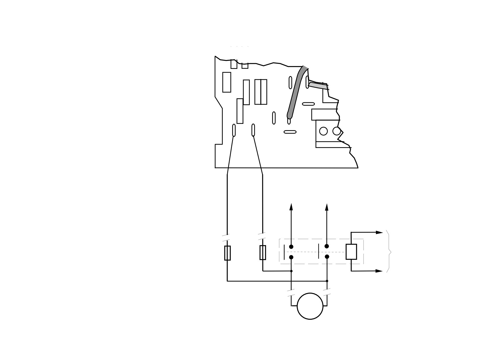
DC Contactor - External Va Sensing
Connections are provided for external armature voltage sensing (at the motor) for when a dc contactor is used between the drive and motor.
Power Board - PCB Reference 385851 (Frame 3)
Installing the Drive
3-35
Power Board - PCB Reference 466701 (Frames 4 & 5)
F13
F14
EX A- EX A+
FL1 FL2
F+ F-
to
to
busbar
busbar
A+
A-
contactor
to
Fuses - only necessary for
terminals
local leads longer than 3 metres
3 & 4 (TB2)
Locate fuses close to signal
source when fitted
M