Parker 590+ series Frame 1, 2, 3, 4, 5, 6 & H. Product Manual (2012) - page 5
3-36 Installing the Drive
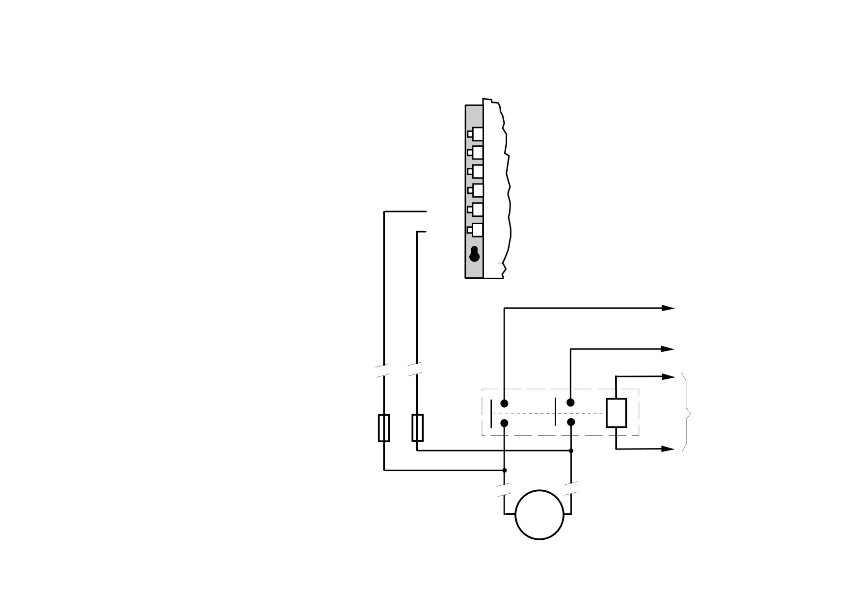
External Connections (Frames 6 & H)
Motor field
FL1
supply and
FL2
and output
terminals plus
F+
external armature
F-
voltage sense
MVA+
MVA-
to
busbar
A+
to
busbar
A-
contactor
to
power
Fuses - only necessary for
control
local leads longer than 3 metres
terminals
Locate fuses close to signal
N & MC
source when fitted
M
Installing the Drive
3-37
Power Board Circuit Descriptions
AH470280U001, U002, U003, U004 (Frame 1)
(2 Quad and 4 Quad)
TB4
Power supplies for the controller are generated from the single
CONN 26
CONN 4
phase auxiliary supply via a Switched Mode Power Supply. The
(to heatsink thermistor)
(to control board)
incoming supply is directly rectified to provide a high voltage dc
heatsink
power rail. A high voltage transistor switches this rail on to the
primary of a high frequency transformer, the output of which is
TP6
T11
T8
TP1
rectified and smoothed to provide the dc power supply rails. The
TP7
TP3
TP4
+15V dc rail is monitored via a reference element and a control
T9
TP8
TH 3
TP9
T12
T15
signal returned via an opto-isolator to the control element of the
("regen" - 4Q)
TP2
TP5
T7
high voltage switching transistor. The other dc rails (-15V & +24V
T10
dc) are generated via separate secondary windings which are
rectified and smoothed, with a separate SMPS element providing a
regulated +5V dc rail. The SMPS operates over a0n input voltage
range of 110V to 240V ac ±10%, 50/60Hz.
T2
T5
TH 2
T6
("motor" - 2Q)
T3
T4
T1
CONN 24
(to fan 24V dc)
CONN 1
(to terminal board)
TB5
TB6
TB7
TB8
TB9
CT
CT
T20
LK8
LK9
LK10
TH1
RLY1
T21
CONN 2
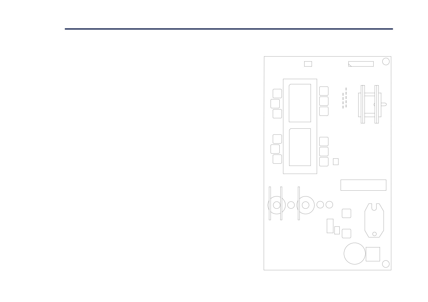
Figure 3- 13
590+ Power Board 4 Quad
TB3
3-38 Installing the Drive
TERMINAL BOARD
POWER BOARD
CONN 1
(to power board)
-
reverse bridge
+
field fuses
L1
armature
FS6
L2
voltage
FS5
feedback
L3
+
forward bridge
aux. supply fuse
-
FS7
TB1
TB2
TB3
A-
A+
armature
current
heatsink fan
feedback
heatsink
heatsink
thermistor
overtemperature
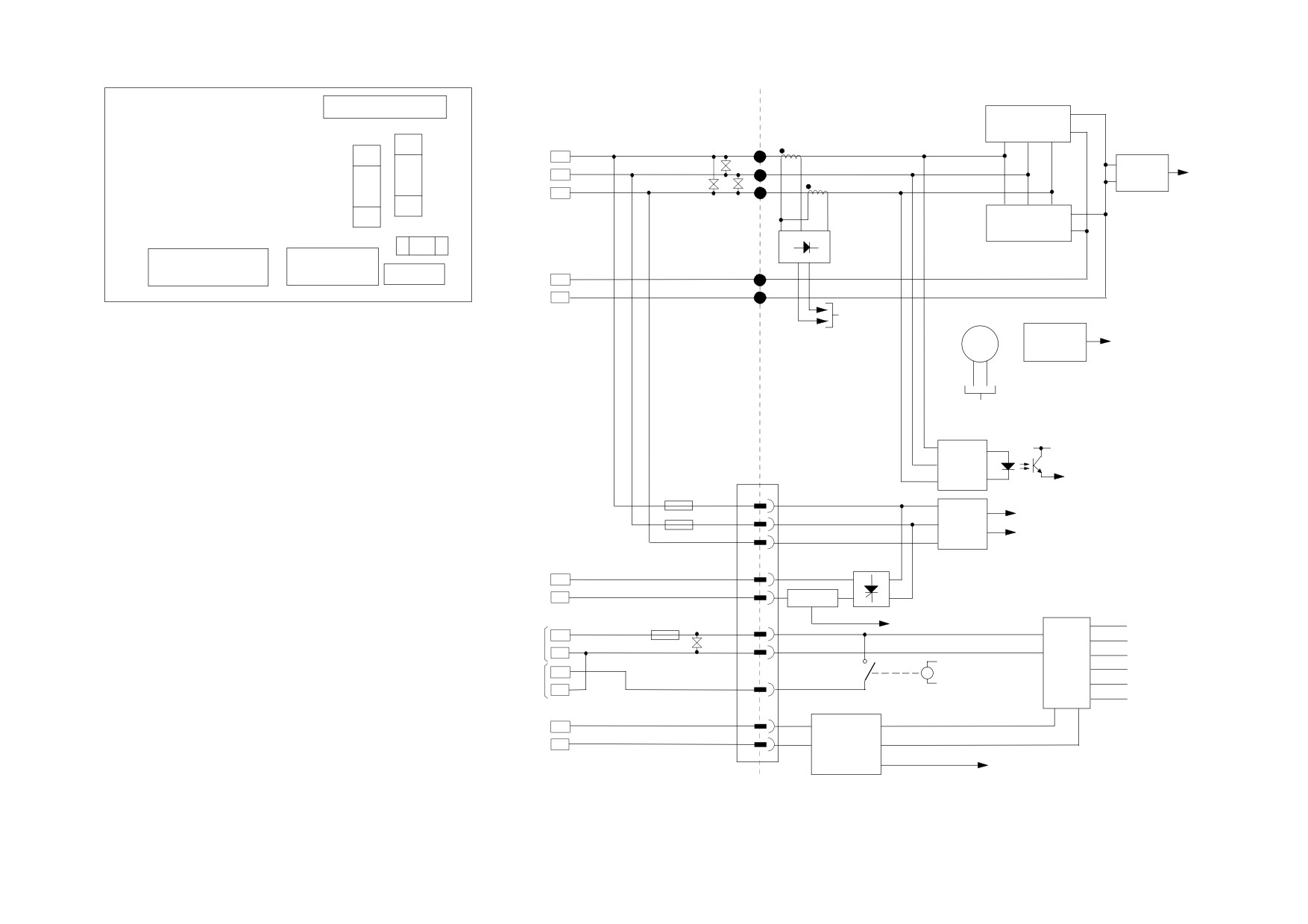
Figure 3- 14 Terminal Board - AH466407
+24V supply
3 phase
present
3 phase present
conn
1
FS5
coding &
coding
phase
FS6
rotation
phase rotation
field bridge
F-
F+
DC CT
FS7
field current feedback
+24V
L
control
+15V
N
+5V
SMPS
3
main contactor pilot
0V
MC
-15V
4
-24V
TH1
motor
TH2
thermistor
isolated motor overtemperature
Figure 3- 15 Connection Diagram for Power Board
and Terminal Board - AH470280 (Frame 1)
Installing the Drive
3-39
AH470330 (Frame 2)
(2 Quad and 4 Quad)
Power supplies for the controller are generated
CONN 29
from the single phase auxiliary supply via a
(to control board)
Switched Mode Power Supply. The incoming
supply is directly rectified to provide a high
test points
T4
T1
T6
T3
T2
T5
voltage dc power rail. A high voltage transistor
switches this rail on to the primary of a high
frequency transformer, the output of which is
rectified and smoothed to provide the dc power
supply rails. The +15V dc rail is monitored via a
CONN 30 (heatsink thermistor))
reference element and a control signal returned via
CONN 47 (fan)
Power Board
an opto-isolator to the control element of the high
voltage switching transistor. The other dc rails
CONN 46 (fan)
(-15V & +24V dc) are generated via separate
secondary windings which are rectified and
smoothed, with a separate SMPS element
providing a regulated +5V dc rail. The SMPS
T7
T10
T9
T12
T11
T8
operates over an input voltage range of 110V to
240V ac ±10%, 50/60Hz.
TB 13
SMPS
transformer
CONN 27
CONN 16
transformer
option
FS6
FS3
3 phase and
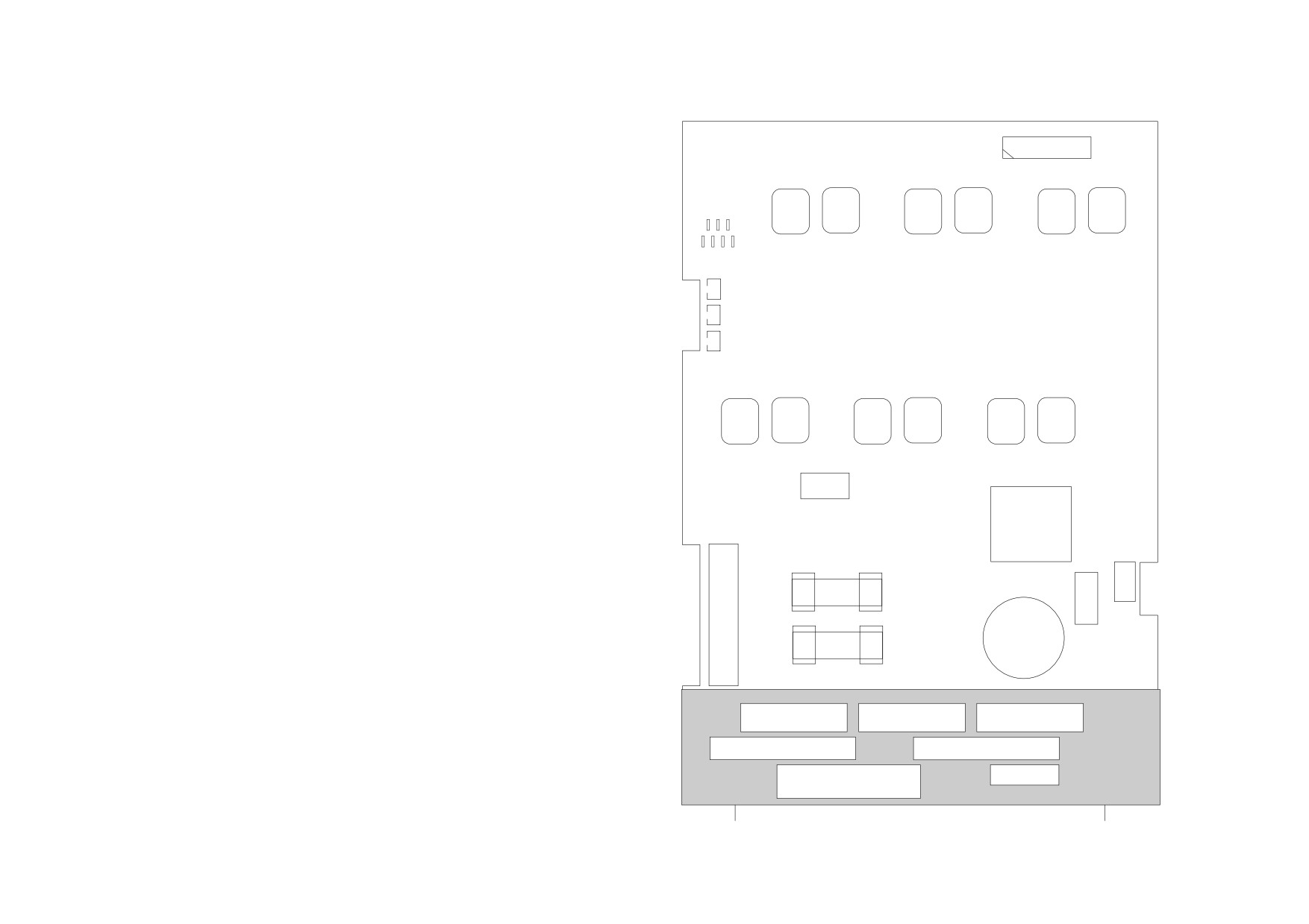
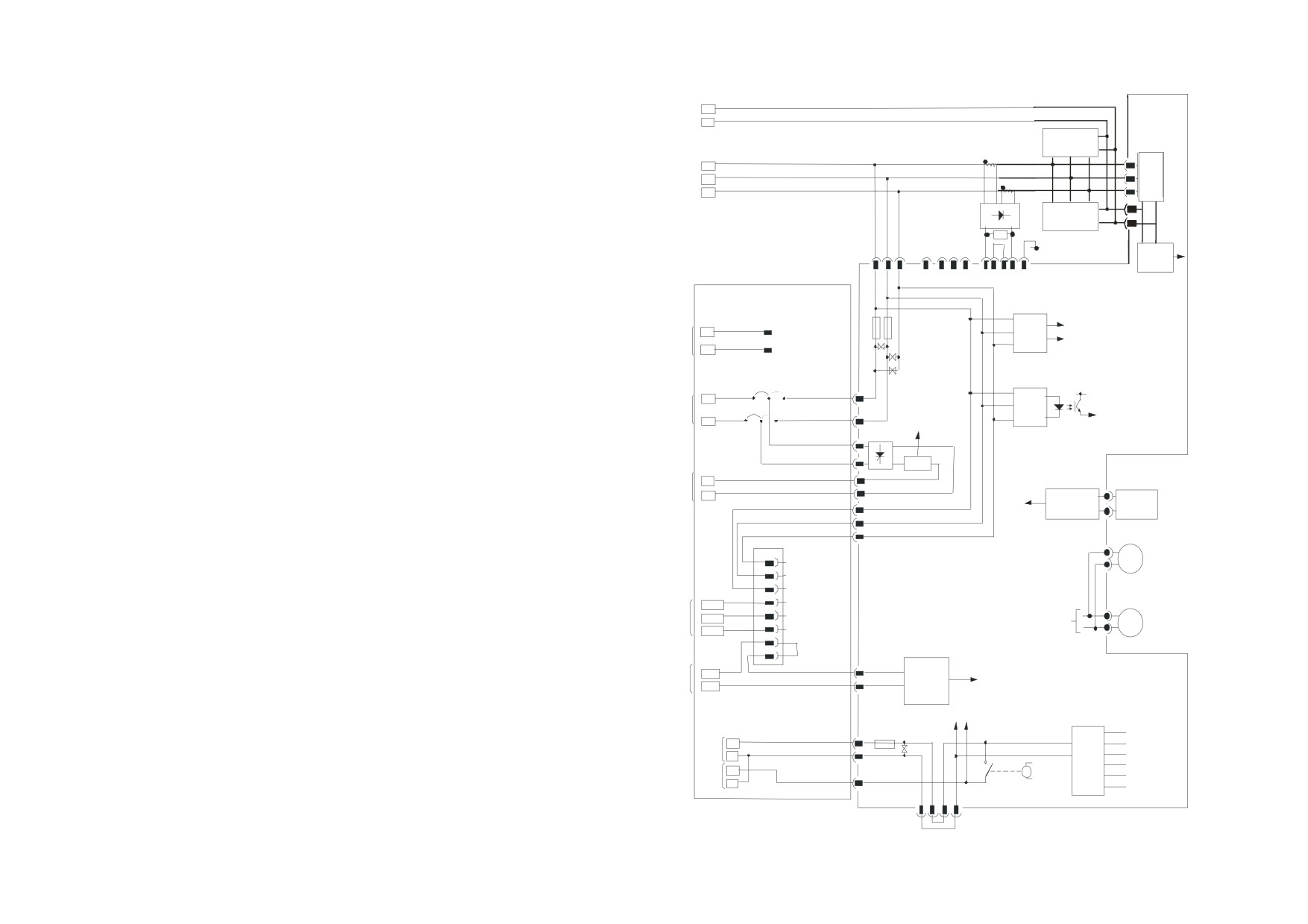
Figure 3- 16
590+ Power Board
main contactor
field fuses
coil
aux.
4 Quad (AH470330)
fuse
FS5
CONN 17
CONN 44
TB6
TB5
Terminal Board
3-40 Installing the Drive
POWER TER MINALS
A-
A+
-
suppression
reverse bridge
components
+
L1
L2
L3
forward bridge+
-
0V
armature
voltage
feedback
MC coil
armature current
feedback
TERMINAL BOARD
FS5
FS6
coding &
coding
A1
phas e
MC Aux
rotation
phase rotation
A2
FL1
Field
3 phase
present
Supply
3 phase present
FL2
field
current f/b
inter nal/external
field bridge
field supply
selector
POWER BO ARD
DC CT
F+
Field
F-
heats ink
heatsink
overtemperature
thermis tor
conn 1
motor
fan
heatsink
circuit
fans
breaker
Vent
M1/U
not
Fan
M2/V
fitted
+24Vs upply
Motor
M3/W
shorting
connector
Motor
TH1
motor
Thermis tor
is olated motor overtemperature
TH2
thermistor
MC coil
FS7
+24V
L
+15V
control
N
+5V
main
SMPS
0V
3
contac tor
MC
pilot
-15V
4
MC coil
-24V
Figure 3- 17 AH470330 (Frame 2)
trans former option
Installing the Drive
3-41
AH385851U002, U003, U004, U005 (Frame 3)
(590+ - 4 Quad, 591+ - 2 Quad; Low and High Volt)
Power supplies for the controller are generated from the
single phase auxiliary supply via a switched mode power
supply. The incoming supply is directly rectified to provide
a high voltage dc power rail. A high voltage transistor
switches this rail on to the primary of a high frequency
transformer, the output of which is rectified and smoothed
to provide the dc power supply rails. The +5V dc rail is
monitored via a reference element and a control signal
returned via an opto-isolator to the control element of the
high voltage switching transistor. The ±15V dc rails are
generated via separate secondary windings which are
rectified, smoothed and stabilised by linear regulators. The
SMPS operates over an input voltage range of 110V to
240V ac ±10%, 50/60Hz. The auxiliary supply fuse FS1
provides protection of the high voltage elements.
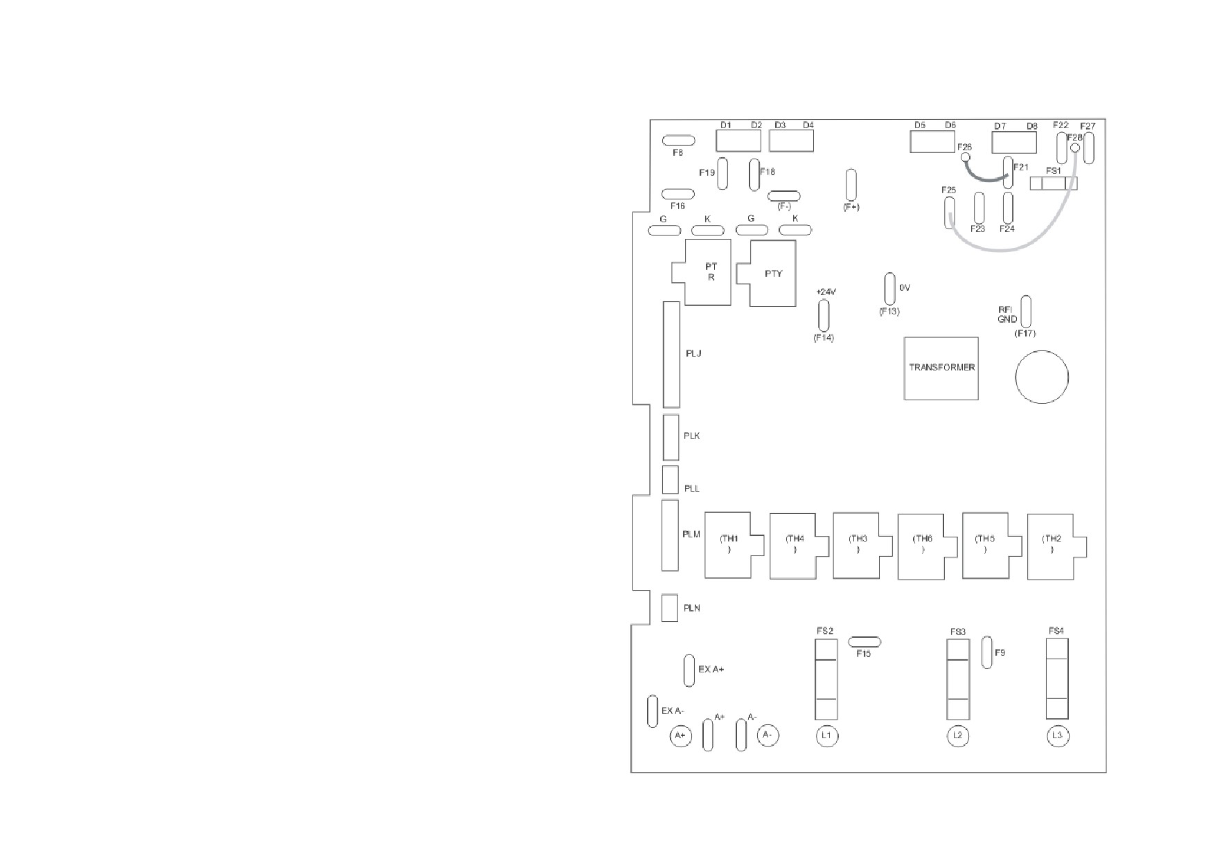
Figure 3- 18
591 Power Board 2 Quad
(AH385851U003, U004)
3-42 Installing the Drive
Heatsink Cooling Fan Connections
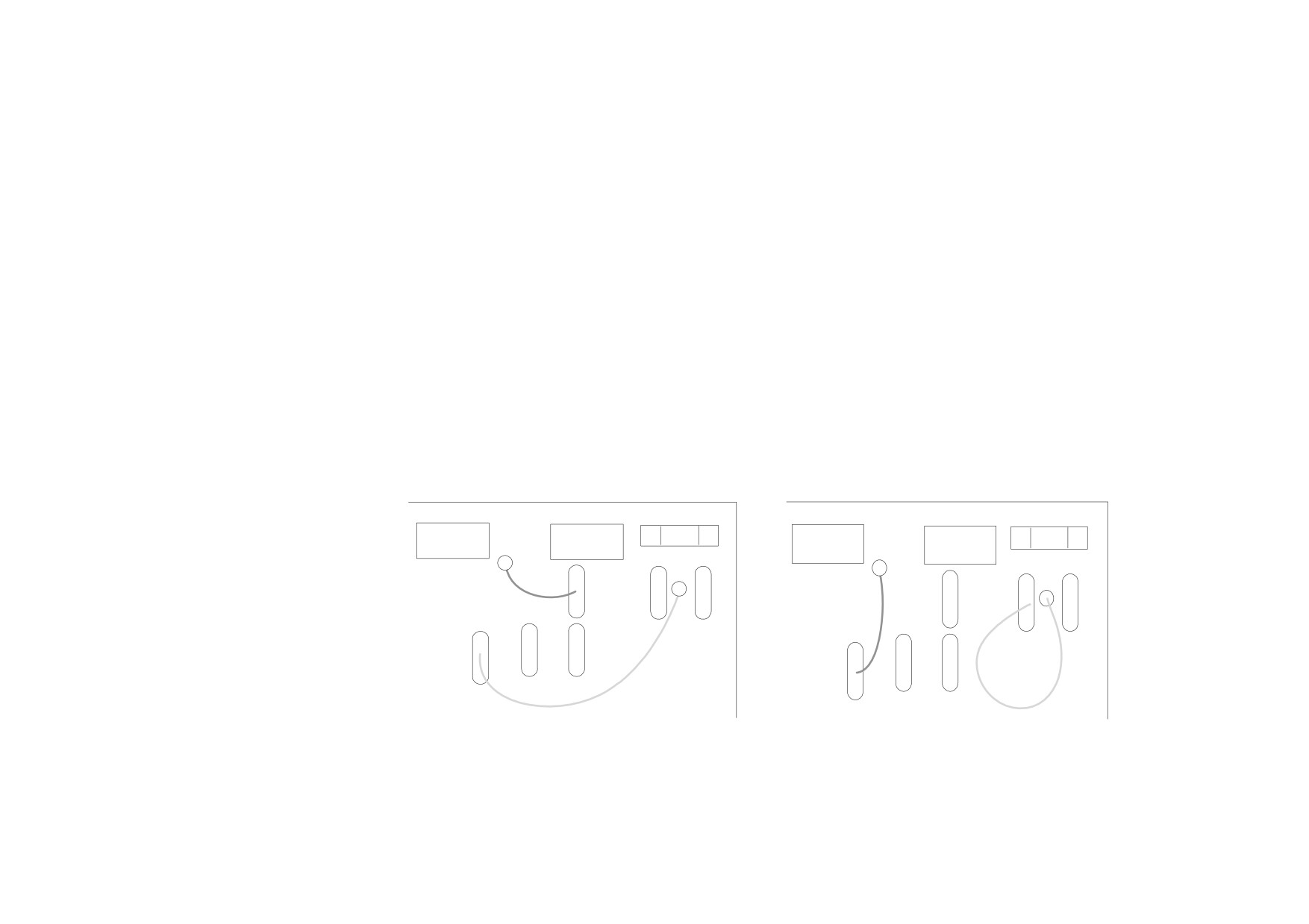
When fitted, these fans are connected on the power board to FAN LIVE (F27), FAN NEUTRAL (F24) and FAN COMMON (F23) as described below:
• A single fan must be matched to the auxiliary supply and connected to F27 and F24.
• Two fans using a 110/115V auxiliary supply must be connected in parallel to F27 and F24.
• Two fans using a 220/240V auxiliary supply must be connected in series to F27 and F24 using F23 as the centre point.
Contactor Supply
The controller requires an ac or dc power contactor in series with the main power path to ensure correct power-up sequencing. This contactor is
directly initiated by the Microcontroller via an isolating relay which drives the contactor coil with the same voltage as that of the auxiliary supply.
This is achieved by the brown wire connection from COIL LIVE (F28) to RELAY (F25) and the blue wire connection from COIL NEUTRAL (F21) to
CONTACTOR RETURN (F26).
However, if an alternative supply for the contactor coil is required move the brown wire from F25 to F22 , and move the blue wire from F21 to F25.
The external coil supply can now be switched using a volt-free contact between terminals D5 and D6.
D5
D6
D7
D8
FS1
D5
D6
D7
D8
FS1
F26
F26
F22
F27
F22
F27
F28
F21
F28
F21
F25
F25
F23
F24
F23
F24
Installing the Drive
3-43
motor voltage feedback
POWER BOARD
A+
TH1
TH3
TH5
L1
L2
L3
TH4
TH6
TH2
A-
H/S
thermostat
A+
L1
L2
L3
A-
1
2
3
4
5
6
PLN
FS2
FS3
FS4
A+
A-
EXA+
EXA-
1
2
ACCT PRESENT
VA FEEDBACK
+
-100
current feedback
(F15)
(F8)
-
FL1
FL2
3 PHASE PRESENT
HIGH VOLTAGE
CODING
F-
INTERFACE
PHASE ROTATION
-
BROWN
GREY
D3
(F6)
FL1 (F15)
RED
FL2 (F9)
VIOLET
YELLOW
SUPPRESSION
+
ORANGE
CIRCUITS
D4
(F7)
F+
G1
G2
FE1 (F19)
ORANGE
D1
FE2 (F18)
RED
YELLOW
ORANGE
D2
1
2
ACCT FIELD
PLL
GR KR GY KY
D5
D5
CONTACTOR RETURN
RLY
F26
RLY
D6
CONTACTOR RETURN
F26
D6
F25
F24
FAN
F21
F24
FAN
RELAY
NEUTRAL
+24
F21
F25
NEUTRAL
+24
RELAY
D7
+15
D7
+15
COIL
F27
F22
FAN
POWER
+5
COIL NEUTRAL
FAN
NEUTRAL
COIL
COMMON
POWER
+5
F23
SUPPLY
0
COMMON
LIVE
F22
F23
SUPPLY
0
D8
-15
COIL
-15
F28
FAN
LIVE
FS1
-24
LIVE
-24
D8
F28
F27
FAN
FS1
LIVE
STANDARD WIRING FOR SWITCHED SUPPLY TO CONTACTOR COIL
ALTERNATIVE WIRING FOR VOLT-FREE CONTACTOR WIRING
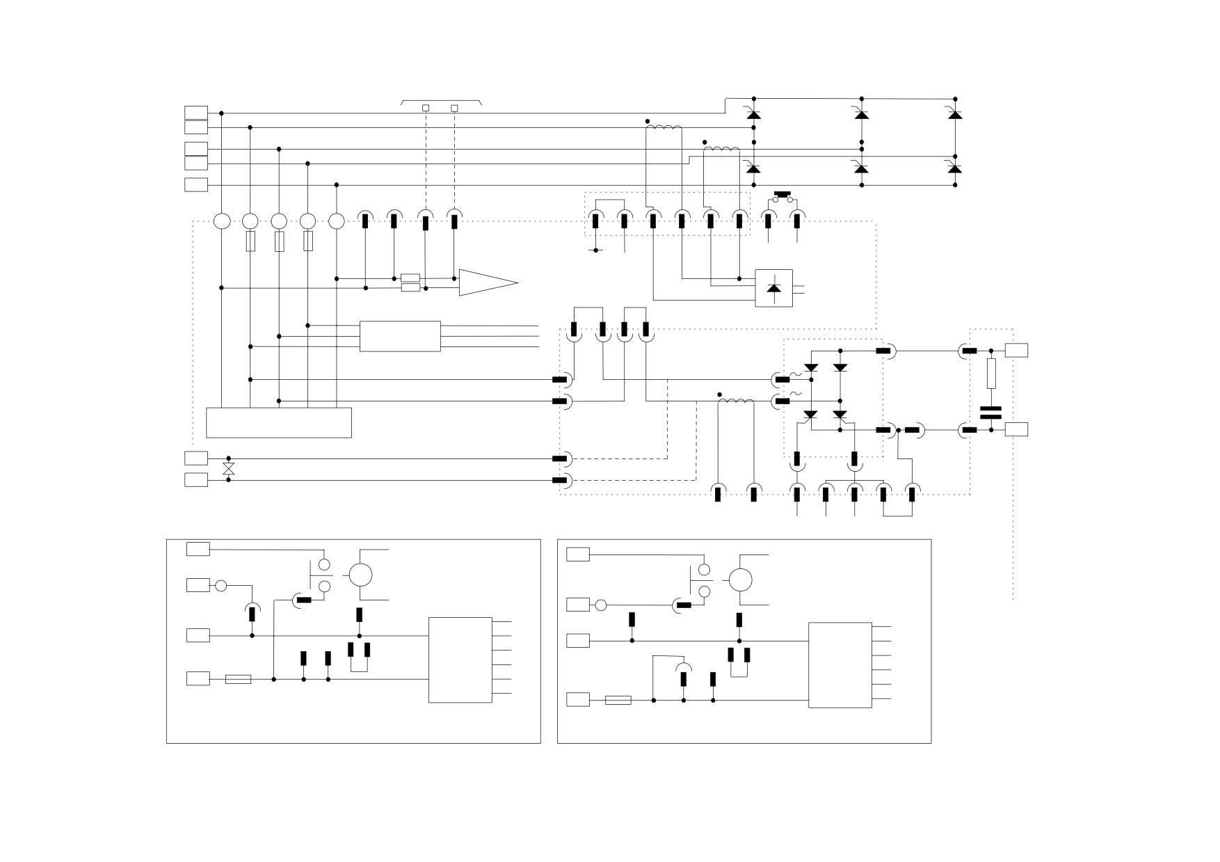
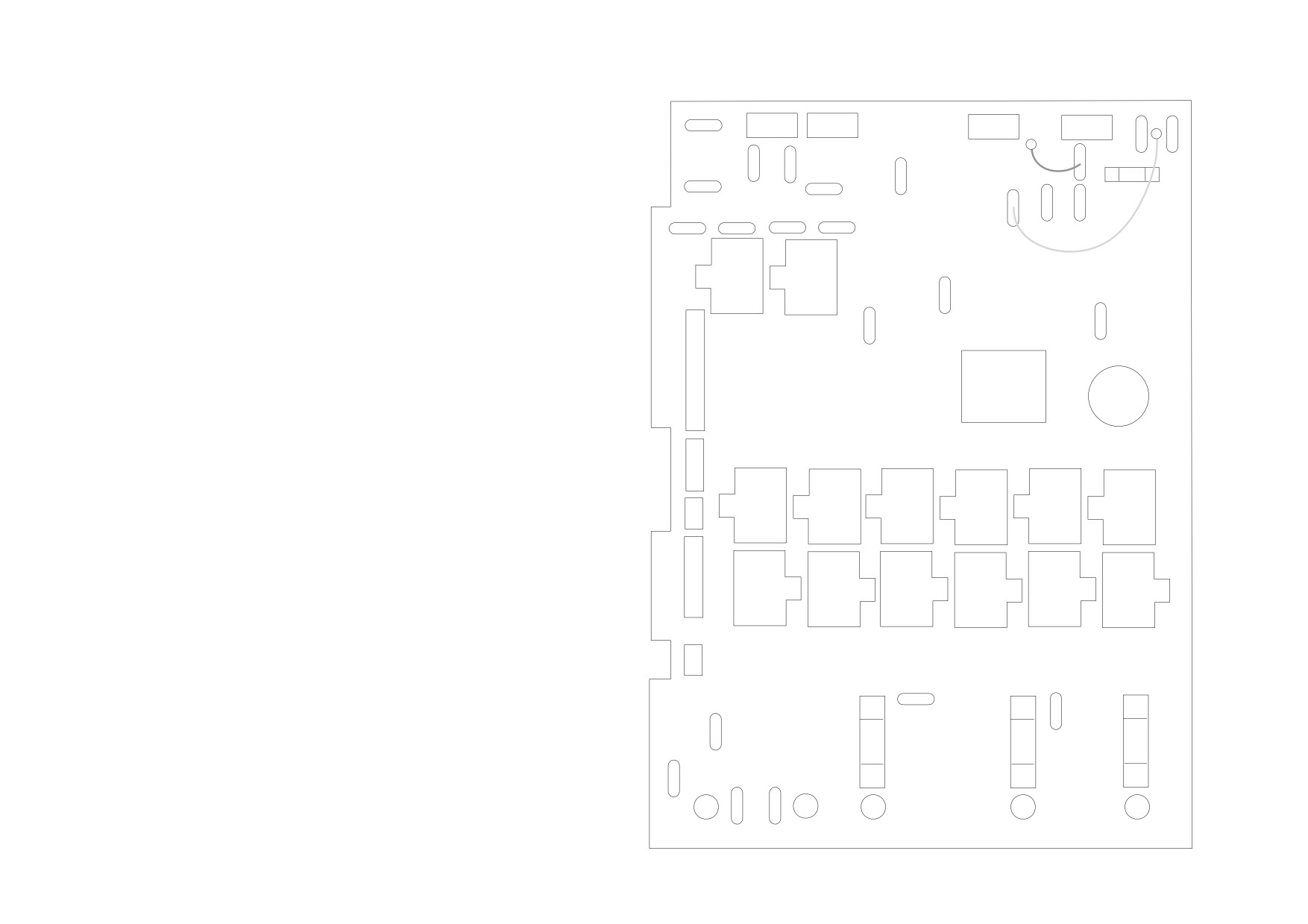
Figure 3- 19
2 Quad Power Circuit - using AH385851U003, U004 (Frame 3)
3-44 Installing the Drive
D1
D2
D3
D4
D5
D6
D7
D8
F22
F27
F28
F26
F8
F21
F19
F18
FS1
F25
F16
(F-)
(F+)
G
K
G
K
F23
F24
PTR
PTY
0V
+24V
(F13)
RFI
GND
(F17)
(F14)
PLJ
TRANSFORMER
PLK
(TH1)
(TH10)
(TH3)
(TH12)
(TH5)
(TH8)
PLL
PLM
(TH7)
(TH4)
(TH9)
(TH6)
(TH11)
(TH2)
PLN
FS2
FS3
FS4
F15
F9
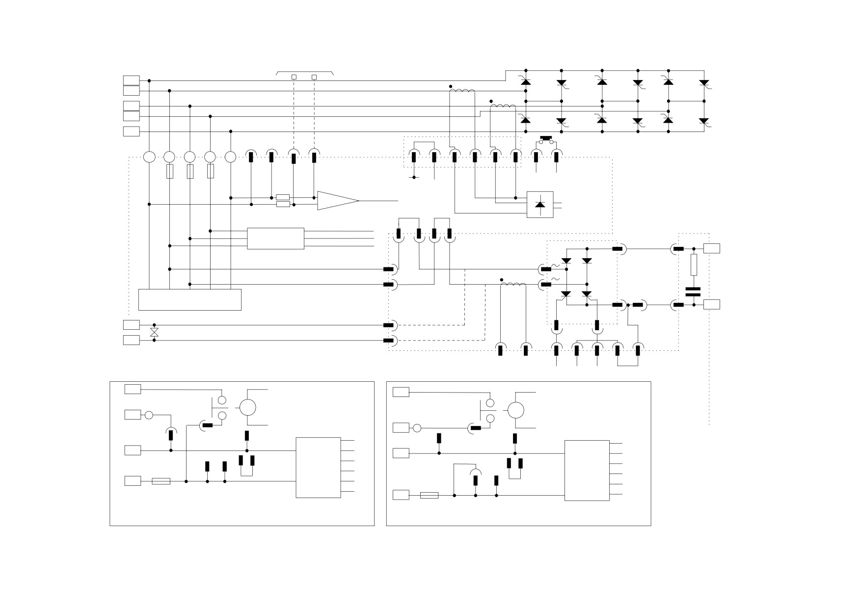
Figure 3- 20
590 Power Board
EX A+
4 Quad
(AH385851U002, U005) - (Frame 3)
EX A-
A+
A-
A+
A-
L1
L2
L3
Installing the Drive
3-45
POWER BOARD
motor voltage feedback
A+
TH1
TH10
TH3
TH12
TH5
TH8
L1
L2
L3
TH4
TH7
TH6
TH9
TH2
TH11
A-
H/S
thermostat
A+
L1
L2
L3
A-
1
2
3
4
5
6
PLN
FS2
FS3
FS4
A+
A-
EXA+
EXA-
1
2
ACCT PRESENT
VA FEEDBACK
+
-100
current feedback
(F15)
(F8)
-
FL1
FL2
3 PHASE PRESENT
HIGH VOLTAGE
CODING
F-
INTERFACE
PHASE ROTATION
-
GREY
BROWN
D3
(F6)
FL1 (F15)
RED
FL2 (F9)
VIOLET
YELLOW
SUPPRESSION
+
ORANGE
CIRCUITS
D4
(F7)
F+
G1
G2
FE1 (F19)
ORANGE
D1
RED
YELLOW
FE2 (F18)
ORANGE
D2
1
2
ACCT FIELD
PLL
GR KR GY KY
D5
D5
CONTACTOR RETURN
RLY
F26
RLY
D6
CONTACTOR RETURN
F26
D6
F24
FAN
F21
F25
F24
FAN
NEUTRAL
+24
F21
F25
RELAY
NEUTRAL
+24
RELAY
D7
+15
+15
COIL
D7
F27
F22
FAN
COIL NEUTRAL
NEUTRAL
COMMON
POWER
+5
FAN
+5
COIL
COMMON
POWER
F23
SUPPLY
0
LIVE
F22
F23
SUPPLY
0
-15
COIL
D8
-15
F28
FAN
LIVE
FS1
-24
LIVE
D8
-24
FS1
F28
F27
FAN
LIVE
STANDARD WIRING FOR SWITCHED SUPPLY TO CONTACTOR COIL
ALTERNATIVE WIRING FOR VOLT-FREE CONTACTOR WIRING
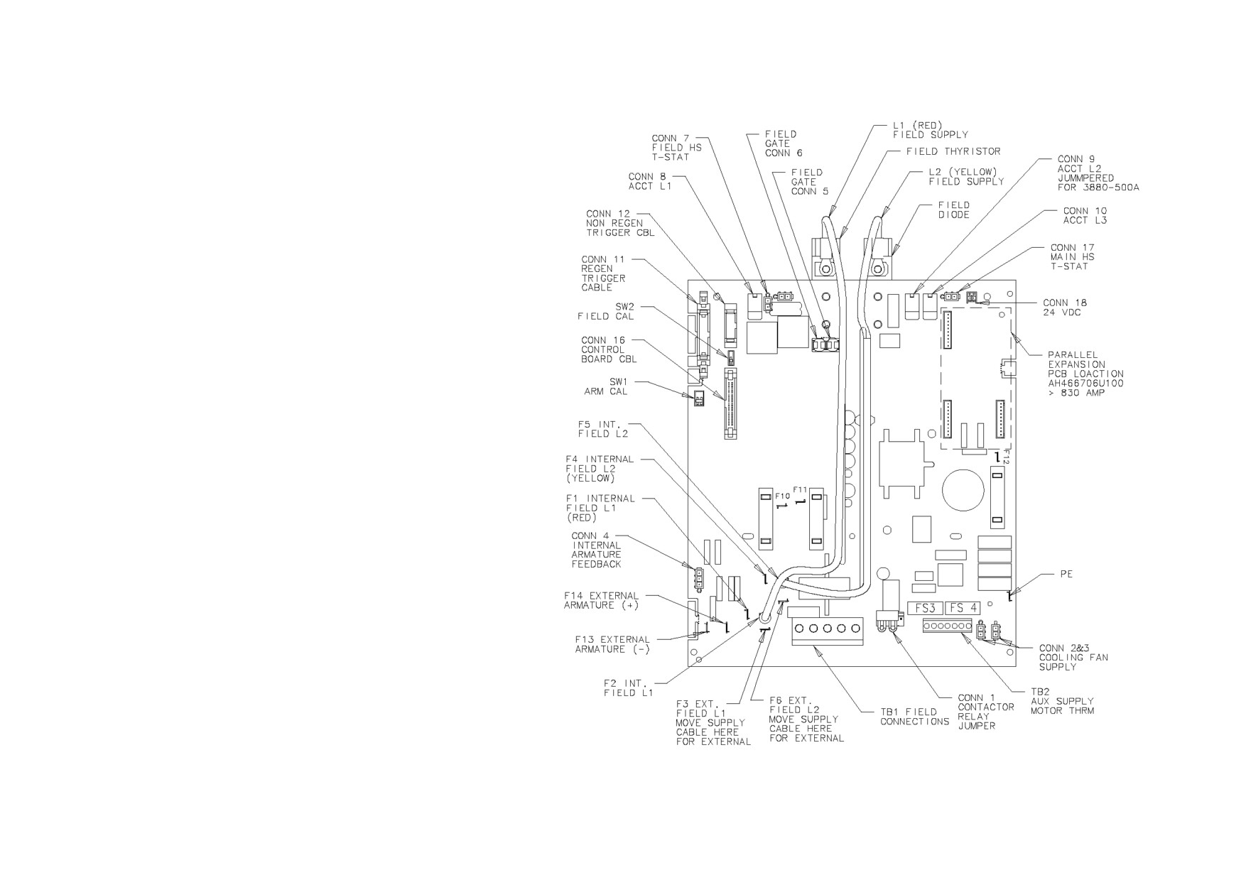
Figure 3- 21
4 Quad Power Circuit - using AH385851U002, U005 (Frame 3)
3-46 Installing the Drive
AH466701U001, U002, U003 (Frames 4 & 5)
590+ 4 Quad and 591+ 2 Quad;
Low, Medium and High Volt
Power supplies for the controller are generated
from the single phase auxiliary supply via a
Switched Mode Power Supply. The incoming
supply is directly rectified to provide a high
voltage dc power rail. A high voltage transistor
switches this rail on to the primary of a high
frequency transformer, the output of which is
rectified and smoothed to provide the dc power
supply rails. The +15V dc rail is monitored via a
reference element and a control signal returned
via an opto-isolator to the control element of the
high voltage switching transistor. The other dc
rails (-15V & +24V dc) are generated via
separate secondary windings which are rectified
and smoothed, with a separate SMPS element
providing a regulated +5V dc rail. The SMPS
operates over an input voltage range of 110V to
240V ac ±10%, 50/60Hz.
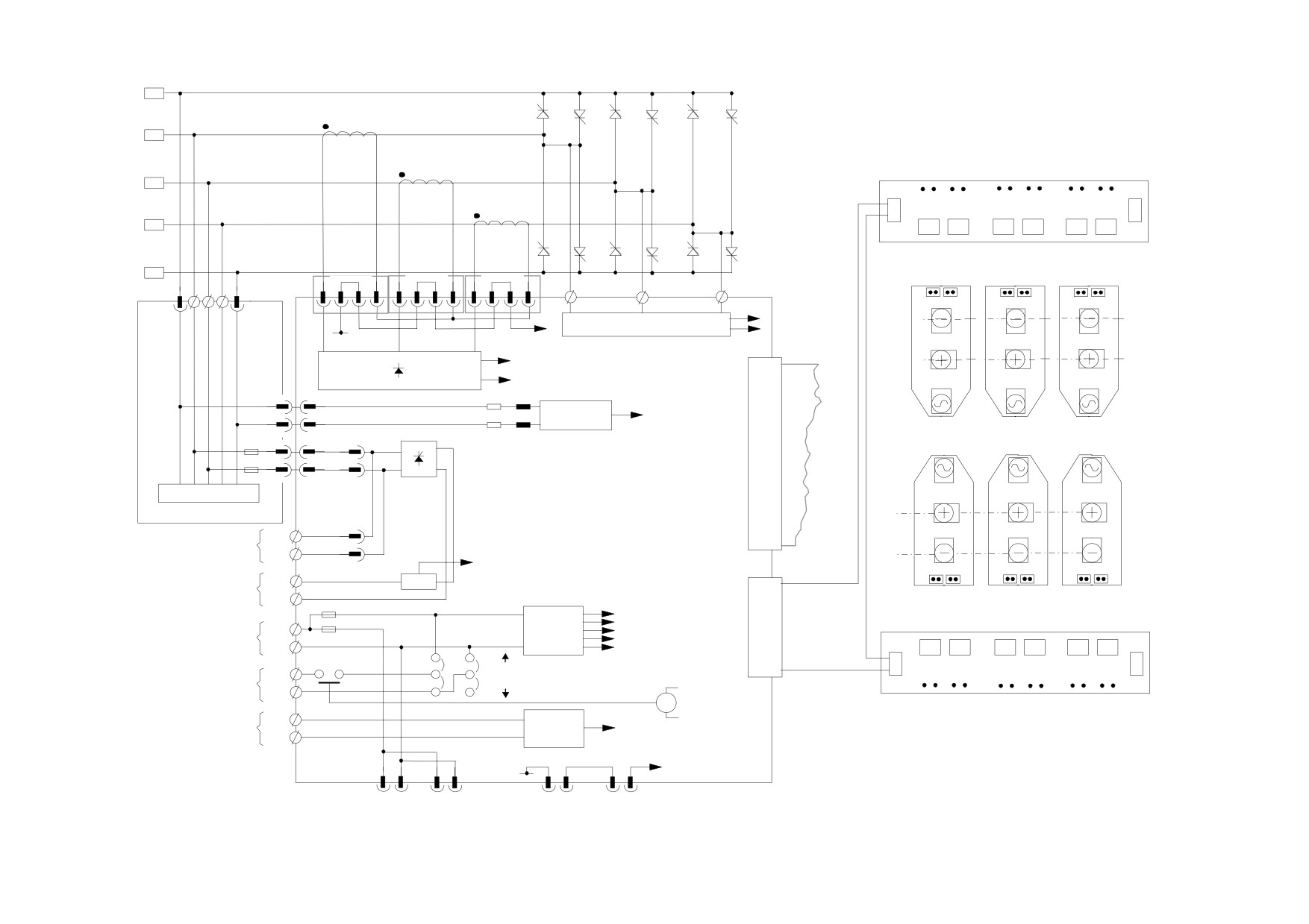
Figure 3- 22
590+/591+ Power Board
Installing the Drive
3-47
A+
G1
K1
TH1
TH10
TH3
TH12
TH5
TH8
L1
TRIGGER BOARD
TH10
TH1
TH12
TH3
TH8
TH5
L2
K G G K
K G G K
K G G K
AH466703U002
L3
TH4
TH7
TH6
TH9
TH2
TH11
A-
CONN8
CONN9
CONN10
TH10 TH1
TH12 TH3
TH8 TH5
3 PHASE PRESENT
A+
CODING & 3 PHASE PRESENT
CODING
ACCT.
0V
PRESENT
A+
CURRENT
FEEDBACK
F14
A+ red
EX A+
ARMATURE
ARMATURE
CONN4
resistors
VOLTAGE
VOLTAGE
FEEDBACK
FEEDBACK
L1
L2
L3
A- gray
F13
FS1
F1
F2
EX A-
50 WAY
red
L1
L2
L3
CONTROL
FS2
yellow
CABLE
F4
F5
INTERNAL
SNUBBER CIRCUITS
FIELD
AH466704U001/2
AH466701U001/2/3
A-
F3
EXTERNAL
FL1
FIELD
EXTERNAL
FL2
FIELD
A-
SUPPLY
FIELD CURRENT
F6
FEEDBACK
MOTOR
F+
DCCT
FIELD
TH7 TH4
TH9 TH6
TH11 TH2
F-
FS3
20 WAY
FS4
POWER
L
SMPS
FIRING
AUXILIARY
SUPPLIES
CABLE
SUPPLY
N
POWERED
AH466703U002
3
K G G K
K G G K
K G G K
MC
VOLT-FREE
4
MAIN CONTACTOR
TH7
TH4
TH9
TH6
TH11
TH2
PILOT RELAY
TH1
TRIGGER BOARD
MOTOR
MOTOR
MOTOR
THERMISTOR
THERMISTOR
OVERTEMPERATURE
TH2
CONN7
CONN17
OVERTEMPERATURE
CONN2
CONN3
USED ON THE DUAL-STACK CONFIGURATION
FAN
FAN
FIELD
ARMATURE
*
THERMOSTAT
THERMOSTAT
Figure 3- 23
4 Quad Power Circuit - Frame 4 & 5 Units using AH466701
3-48 Installing the Drive
A+
G1
K1
TH1
TH3
TH5
L1
L2
L3
TH4
TH6
TH2
A-
CONN8
CONN9
CONN10
3 PHASE PRESENT
CODING & 3 PHASE PRESENT
CODING
0V
ACCT.
PRESENT
CURRENT
FEEDBACK
F14
A+ red
EX A+
ARMATURE
ARMATURE
CONN4
resistors
VOLTAGE
VOLTAGE
FEEDBACK
FEEDBACK
A- gray
F13
FS1
F1
F2
EX A-
50 WAY
red
L1
L2
L3
CONTROL
FS2
yellow
CABLE
F4
F5
INTERNAL
SNUBBER CIRCUITS
FIELD
AH466704U001/2
AH466701U001/2/3
A+
F3
EXTERNAL
FL1
FIELD
EXTERNAL
SUPPLY
FL2
FIELD
FIELD CURRENT
A-
F6
FEEDBACK
MOTOR
F+
DCCT
FIELD
TH1 TH4
TH3 TH6
TH5
TH2
F-
FS3
10 WAY
FS4
POWER
L
SMPS
FIRING
AUXILIARY
SUPPLIES
CABLE
SUPPLY
N
POWERED
AH466703U002
3
K G G K
K G G K
K G
G K
MC
VOLT-FREE
4
MAIN CONTACTOR
TH1
TH4
TH3
TH6
TH5
TH2
PILOT RELAY
TH1
MOTOR
TRIGGER BOARD
MOTOR
MOTOR
THERMISTOR
THERMISTOR
OVERTEMPERATURE
TH2
CONN7
CONN17
OVERTEMPERATURE
CONN2
CONN3
USED ON THE DUAL-STACK CONFIGURATION
FAN
FAN
FIELD
ARMATURE
*
THERMOSTAT
THERMOSTAT
Figure 3- 24
2 Quad Power Circuit - Frame 4 & 5 Units using AH466701
Installing the Drive
3-49
AH469419 (Frame 6)
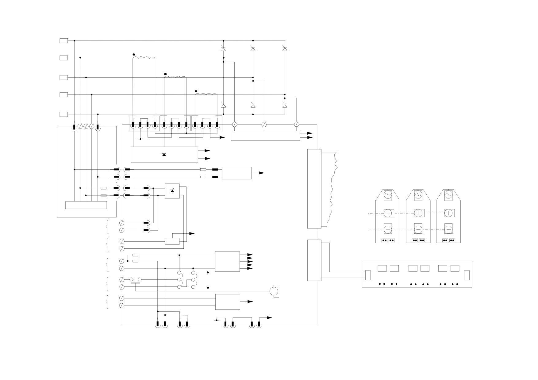
Power supplies for the controller are generated from the single phase auxiliary supply via a Switched Mode Power Supply. The incoming supply is
directly rectified to provide a high voltage dc power rail. A high voltage transistor switches this rail onto the primary of a high frequency transformer,
the output of which is rectified and smoothed to provide the dc power supply rails. The 5V dc rail is monitored via a reference element and a control
signal returned via an opto-isolator to the control element of the high voltage switching transistor. The other dc rails (-15V & +24V dc) are generated
via separate secondary windings which are rectified and smoothed, with individual linear regulators providing ±15V dc rail. The SMPS operates over
an input voltage range of 115V to 230V ac ±10%, 50/60Hz.
3-50 Installing the Drive
AH466001U001, U101 (Frame H)
(590+ - 4 Quad and 591+ - 2 Quad; Low and High Volt)
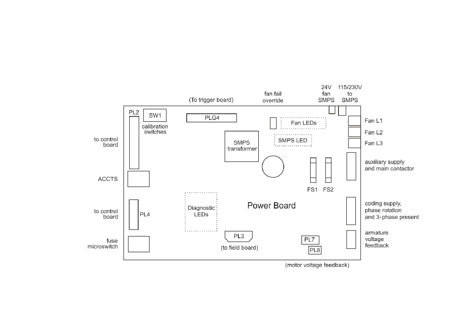
Power supplies for the controller are generated from the single phase auxiliary supply via a Switched Mode Power Supply. The incoming supply is
directly rectified to provide a high voltage dc power rail. A high voltage transistor switches this rail on to the primary of a high frequency transformer,
the output of which is rectified and smoothed to provide the dc power supply rails. The 5V dc rail is monitored via a reference element and a control
signal returned via an opto-isolator to the control element of the high voltage switching transistor. The other dc rails (-15V & +24V dc) are generated
via separate secondary windings which are rectified and smoothed, with individual linear regulators providing ±15V dc rail. The SMPS operates over
an input voltage range of 110V to 240V ac ±10%, 50/60Hz.
Swing-frame
Power Board
Field Board
(to 4Q trigger boards)
PL1
PL12
SW1
calibration
PL13
(to 2Q trigger boards)
switches
to control
auxiliary supply
board
SMPS
TB9
and main contactor
transformer
ACCTS
PL2
PL4
Power Board
coding supply,
phase rotation
TB6
and 3-phase present
to control
board
armature
PL3
TB8
voltage
fuse
PL6
PL7
feedback
microswitch
(to field board)
PL11
PL5
(to 4Q trigger boards)
(motor voltage feedback)
Installing the Drive
3-51
A+
G1
K1
TH1
TH3
TH5
SUPRESSION
SUPRESSION
SUPRESSION
FS1
L1
FS2
L2
2 WAY
FS3
TRIGGER
TRIGGER
TRIGGER
CONNECTOR
L3
TH1 & 4
TH3 & 6
TH5 & 2
R
Y
TH4
TH6
TH2
A-
1
2
3
UPPER
FS7
FS8
FS9
HEAT
ACCT. PRESENT
SINK
0VL
A-
TH4
TH6
TH2
LINE
SUPP.
ACCT.
K
A
FIELD ASSEMBLY
EXT.A-
A-
L3
L2
L1
A+
EXT.A+
THB
FL1
F+
FIELD
AC SUPPLY
FL2
F-
0V
LOWER
HEAT
SINK
A
A+
TH1
TH3
TH5
K
THA
FIELD
CODING, PHASE ROTATION &
3 PHASE PRESENT
L1
L2
L3
Y
R
Power Board
3 WAY
ribbon
CONNECTOR
30 WAY RIBBON TO
TRIGGER
TRIGGER BOARDS
Figure 3- 25
2 Quad Power Circuit - Frame 6 & Frame H Units using AH466001U001