Parker 590+ series Frame 1, 2, 3, 4, 5, 6 & H. Product Manual (2012) - page 3
3-4 Installing the Drive
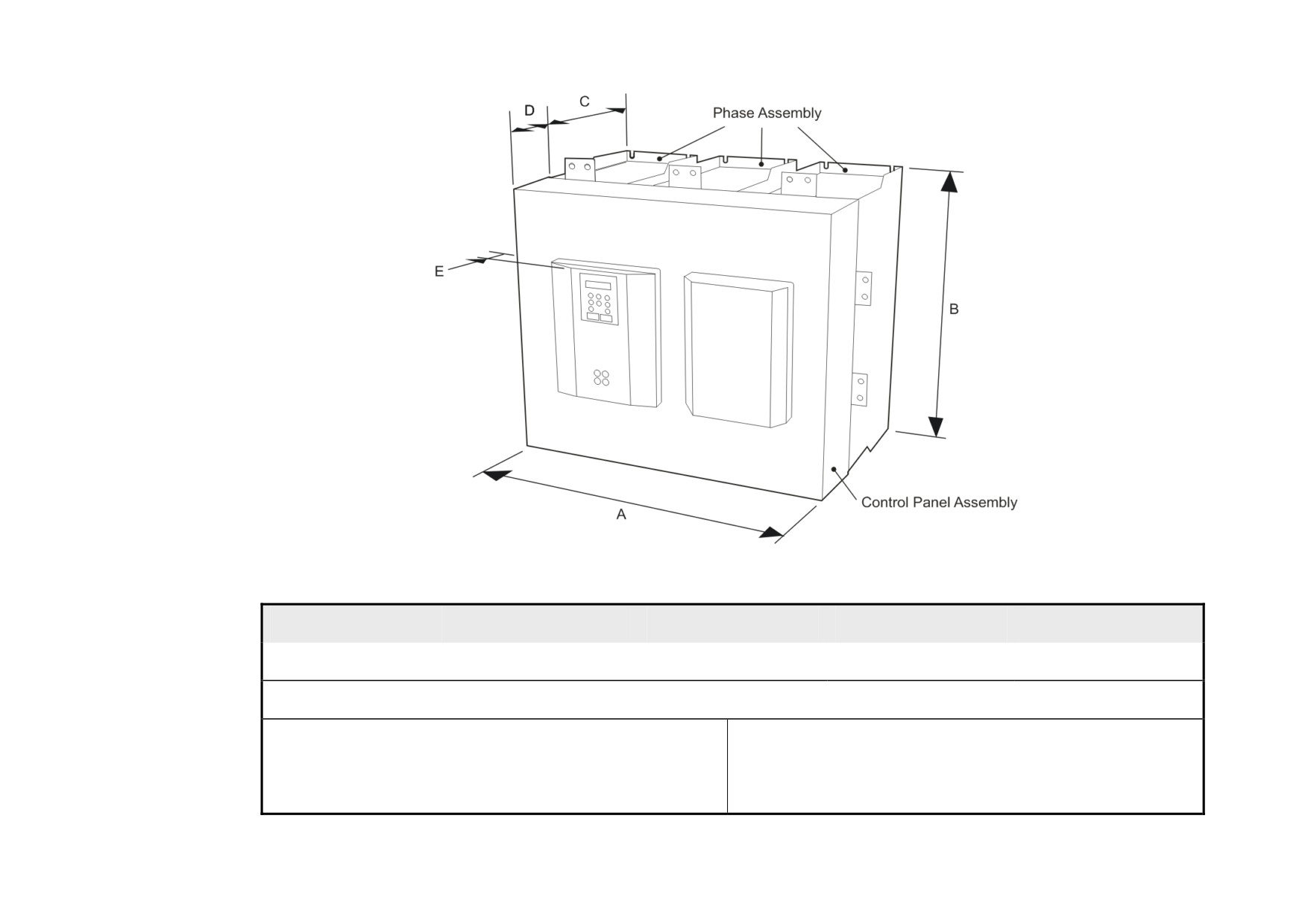
1250 - 1950A
Frame 6
A
B
C
D
E
686 (27.00)
715 (28.15)
378 (14.88)
62 (2.44)
57 (2.24)
Dimensions are in millimetres (inches)
Weights:
The DC590+ Frame 6 drive is assembled in-situ. Refer to "Frame
Control Panel Assembly
11.25kg (25 lbs)
6: Assembly and Installation" page 3-63 for detailed build
Regen Phase Assembly (4Q)
33kg (73 lbs) each
instructions.
Non-Regen Phase Assembly (2Q)
28kg (62 lbs) each
Installing the Drive
3-5
Mounting the Drive
NOTE General installation details are given below for mounting the Drive, however, if you are installing the unit with an
EMC filter refer to “External AC Supply EMC Filter Installation, page 3-60.
Mount the unit vertically on a solid, flat, vertical surface. It is mounted using bolts or screws into four fixing points (keyhole slots). The design allows
the use of 100mm grid fixing.
It must be mounted inside a suitable cubicle. To comply with the European safety standards VDE 0160 (1994)/EN50178 (1998), the cubicle must
require a tool for opening.
NOTE Holes for the mounting bolts or screws must be placed accurately.
Cover any units all ready mounted to the panel to protect them from stray metal filings while drilling mounting holes.
General Mounting Hints
Caution
Use proper lifting techniques when lifting and moving.
Drill the mounting holes into the backplate. The holes must be positioned accurately. Fit the nut inserts. Fit bolts and washers into the top inserts so
that the drive can be hung using the keyhole slots.
Hang the drive on the bolts, between the panel and washers you have just fitted. Fit bolts and washers to the lower nut inserts. Finally, use the socket
wrench to tighten all nuts securely.
Check the drive and its housing for packing material, mounting debris, or any other material that could damage and/or restrict the operation of the
equipment.
Recommended Tools
Socket wrench
With a 6 Inch extension
Deep sockets
M6, M10, M13, M17, 7/16”, 1/2”
Screwdrivers
Phillips No.2, flat blade - 0.5 x 3.0mm, 0.8 x 4.0mm
Wire cutters
Small
3-6 Installing the Drive
Ventilation and Cooling Requirements
NOTE When fitting a drive into a sealed enclosure additional cooling MUST be provided, otherwise the internal air will
overheat causing the drive to trip on "overtemperature".
Refer to Appendix E: “Technical Specifications” - Cooling Fans.
The Drive gives off heat during normal operation and must therefore be mounted to allow the free flow of air through the air entries and exits.
Maintain the minimum air clearances given on the drawings to ensure that heat generated by other adjacent equipment is not transmitted to the Drive.
Be aware that other equipment may have its own clearance requirements. When mounting two or more DC590+’s together, these clearances are
cumulative.
Ensure that the mounting surface is normally cool.
Installing the Fan (Frame H)
Refer to Appendix E: “Technical Specifications” - Cooling Fans.
The fan unit supplied should be installed on the cubicle, with or without ducting (refer to the Installation Drawing). The drive is force-cooled using the
fan units supplied with the drive. As a general rule allow at least 150mm (6 inches) of clear space above and below the drive for free air flow. We
suggest the cubicle has an air inlet at the base of the cubicle equivalent to 0.37m2 (4ft²), variable depending upon the filter type used, to allow the
maximum throughput of air.
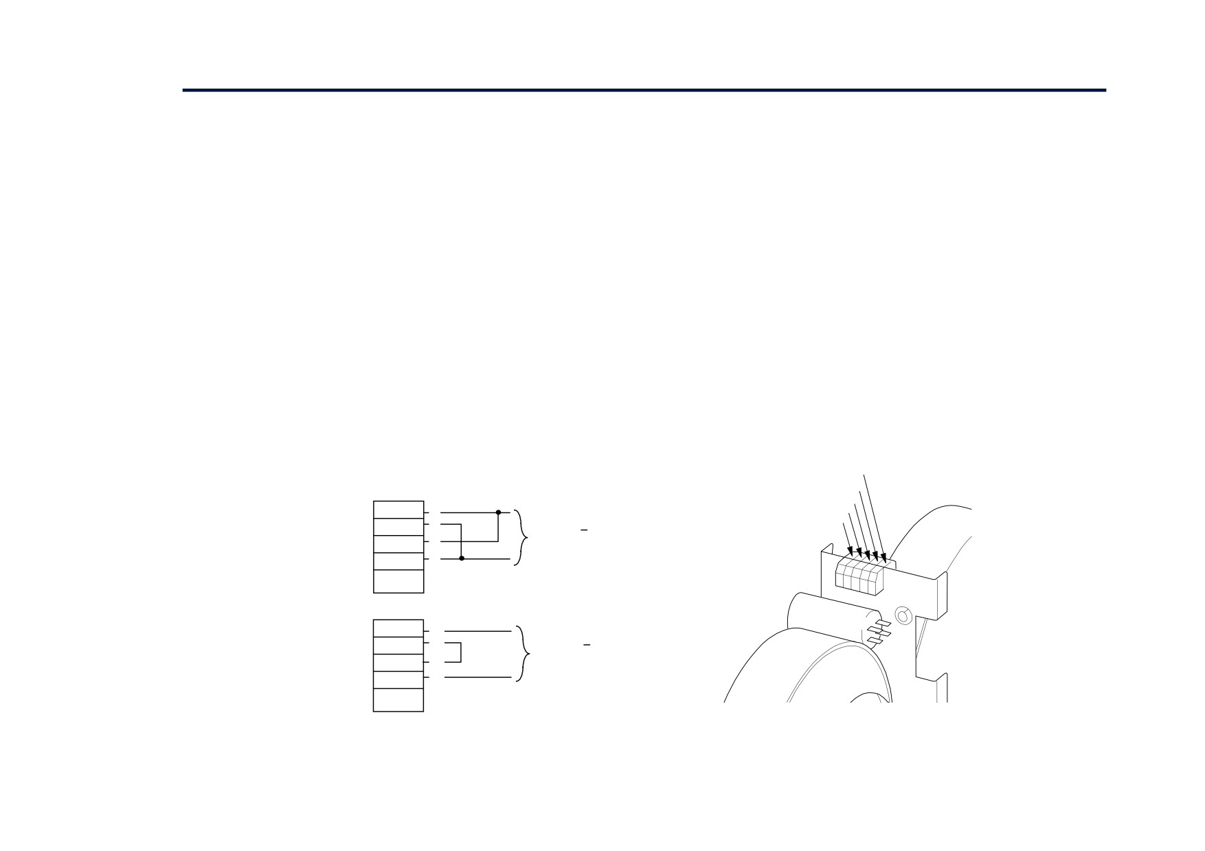
The fan assembly provided is permanently wired as shown below.
PE/GRD
FN4
115V ac
FN3
L
FN2
1
L
115V ac + 10%
FN1
2
N
50/60Hz
3
L
N
4.5A
4
N
PE/GRD
230V ac
L
1
L
230V ac + 10%
2
N
50/60Hz
3
L
N
2.25A
4
N
PE/GRD
Figure 3- 2 Frame H Fan Wiring Diagram
Installing the Drive
3-7
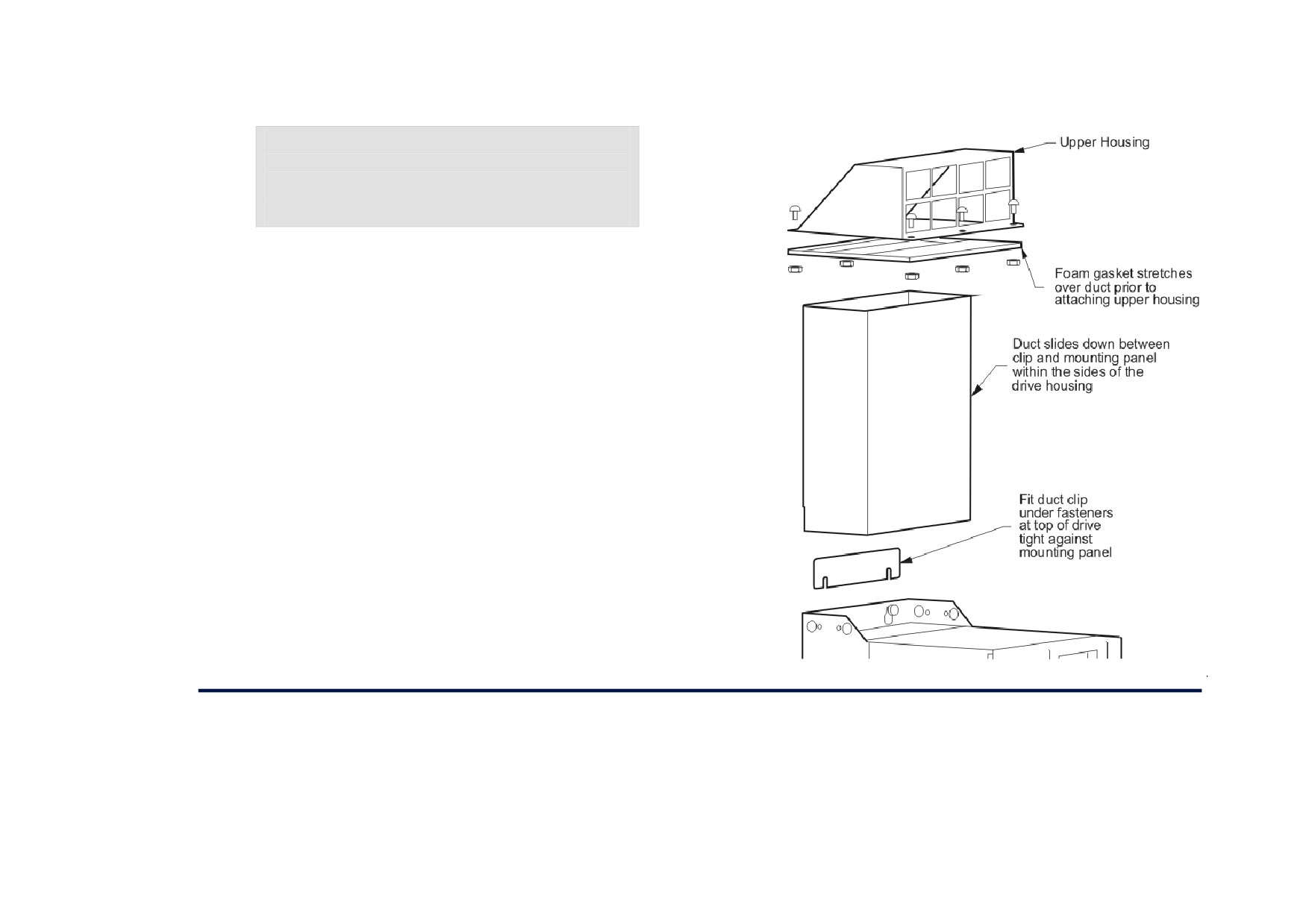
Installing the External Vent Kit (Frames 4 & 5)
Parker SSD Part Drives Numbers:
Frame 4 : LA466717U001
Frame 5 : LA466717U002
Refer also to page 3-80 and page 3-85.
Figure 3- 3 Frames 4 & 5 External Vent Kit
AC Line Choke
We recommend that you always use the specified ac line choke with the Drive
to provide a known supply impedance for effective operation of the thyristor transient suppression circuits. At least 1% line impedance should be
provided in the supply side of the drive.
Refer to Appendix E: “Technical Specifications” - AC Line Choke for selection details.
3-8 Installing the Drive
Filtering
NOTE Refer to Appendix B: "Certification" - EMC.
For compliance in Europe with EN61800-3 Table 11:
• The CE marking of drives whose armature current >100A is applicable without filtering.
• The CE marking of drives whose armature current <100A is only applicable with filtering. The drive requires one of the following:
1. The specified filter given in Appendix B
(also refer to External AC Supply EMC Filter Installation, page 3-60)
2. Compliant filtering offered by the System
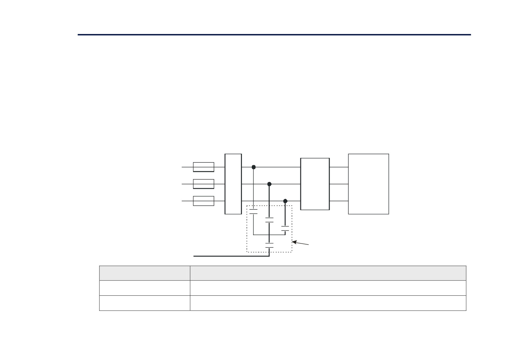
3. Capacitors fitted between phase and earth (see Figure 3- 4 below)
Start
Contactor
AC
Line
Choke
Drive
(must be
fitted)
Suitable Branch
Protection Fuse
or
Circuit Breaker
C1, C2 & C3
590AC Line Choke Filter
C4
CO468398
PE
Capacitor Reference Number
Capacitor Value/Type
C1, C2, C3
3.0μF 400V, EMI suppressor type Class X1
C4
1.0μF 400V, EMI suppressor type Class X1
Figure 3- 4 AC Line Choke and Capacitors fitted to Frame 1 (15A & 35A) & Frame 2 (40A & 70A) Drives
Installing the Drive
3-9
Electrical Installation
IMPORTANT
Please read the Safety Information on page Cont. 3 & 4 before proceeding.
WARNING
Ensure that all wiring is electrically isolated and cannot be made “live” unintentionally by other personnel.
NOTE
Refer to Appendix E: “Technical Specifications” for additional Wiring Requirements for EMC Compliance and Wire
Sizes and Termination Tightening Torques.
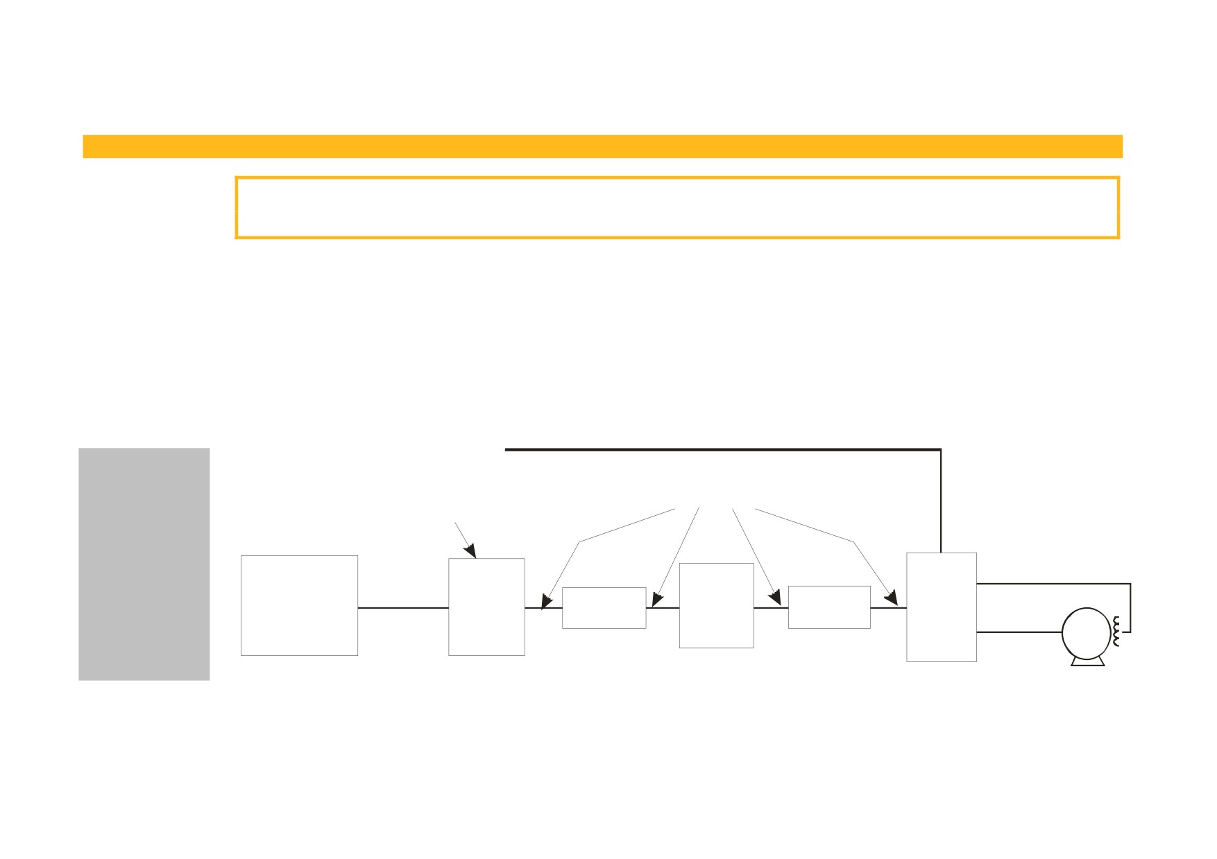
Cables are considered to be electrically sensitive, clean or noisy. You should already have planned your cable routes with respect to segregating these
cables for EMC compliance.
If not, refer to Appendix B: “Certification”.
If the controller is to be operating in a regenerating mode for extended periods acting as a load generator for another machine, it is advisable to fit
additional protection in the armature circuit. A dc fuse or high speed circuit breaker will provide this protection. If in doubt, contact Parker SSD
Drives.
signal/control cable
If fitted, the AC
(sensitive)
filter MUST be
(noisy)
Not fitted to
placed between
Frame H units
the supply and the
choke.
Failure to do so
power
field cable
will result in
fuse or suitable
supply
external
590AC
unreliable
circuit breaker
cable
ac
Line Choke
contactor
choke
drive
(noisy)
operation of the
filter
Filter
(RCD not
drive and reduced
(optional)
CO468398
recommended)
(clean)
motor
lifetime of the
motor cable
filter.
Figure 3- 5 Cabling Requirements
3-10 Installing the Drive
Cable Gland Requirements
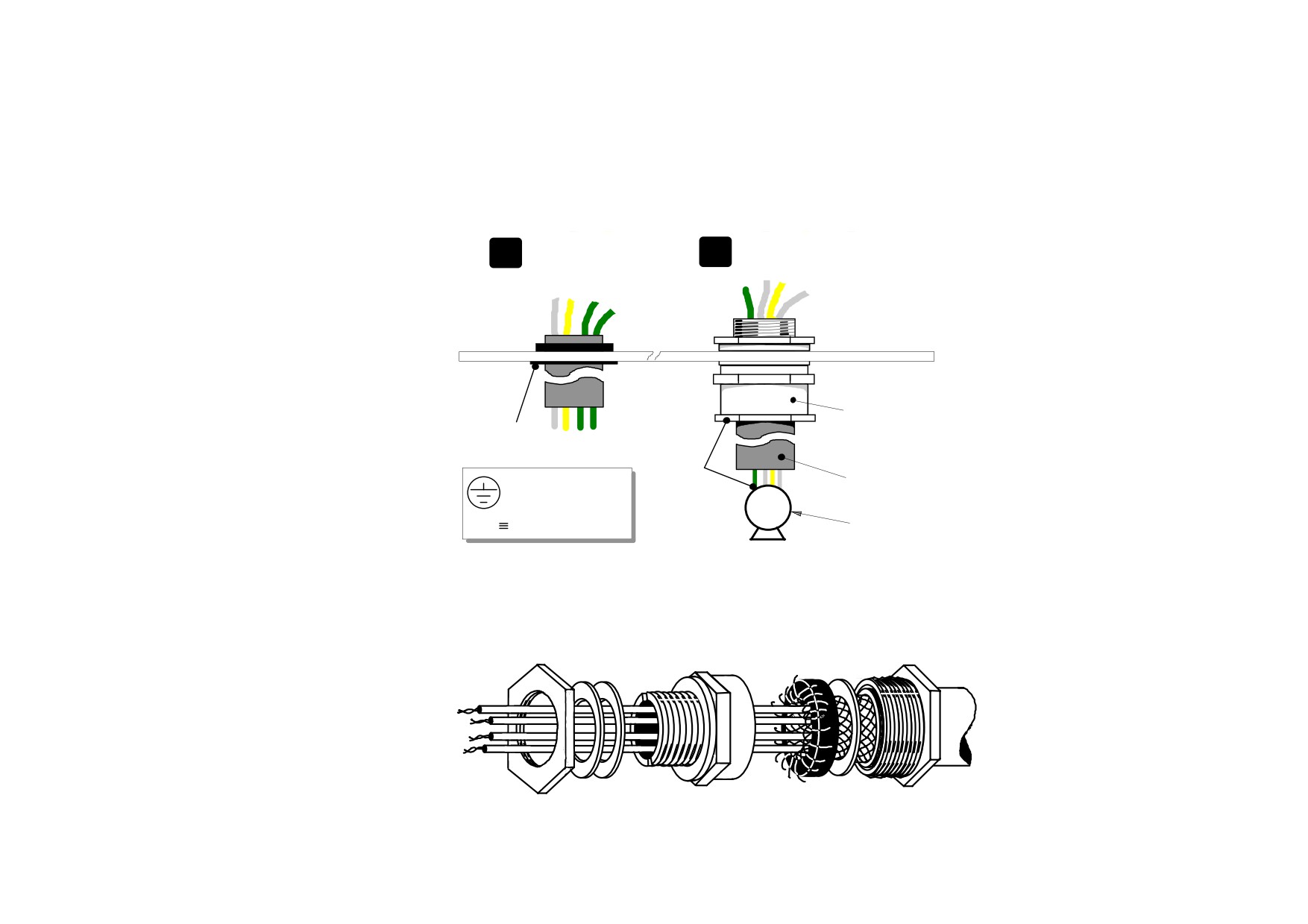
Use a metal gland to connect to the cubicle backplate, near the VSD (variable speed drive). It must be capable of securing a 360 degree screened
connection to give EMC compliance. A 360 degree screened connection can be achieved as shown.
We suggest a rubber grommet is fitted on holes where a cable gland is not used.
rubber grommet
metal cable gland
1
2
metal gland must
have 360 degree
screened connection
rubber
for EMC compliance
grommet
PE
power wiring
International
to motor
grounding symbol
M
PE Protective Earth
for example
Figure 3- 6 Cable and Screen Fixings
Figure 3- 7
360 Degree Screened Connection

Installing the Drive
3-11
Minimum Connection Requirements
IMPORTANT
If in doubt about the connection of the DC motor to the drive, contact Parker SSD Drives.
NOTE Because of the complexity of showing all possible configurations, this Chapter deals only with a `general purpose’
operation as a basic speed controller. Special wiring options usually form part of a customer-specific system and
connection details will be provided separately.
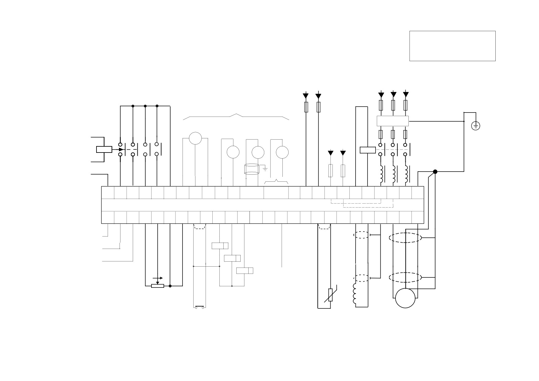
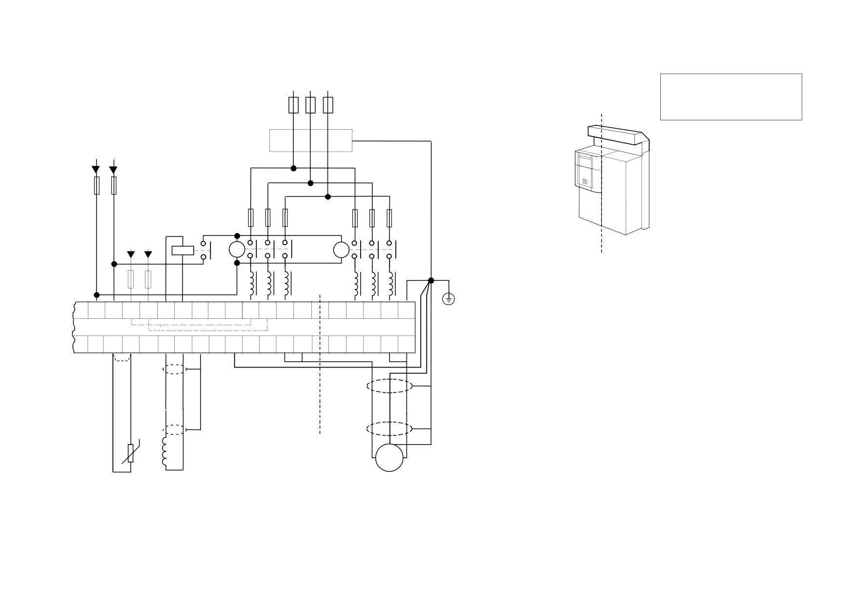
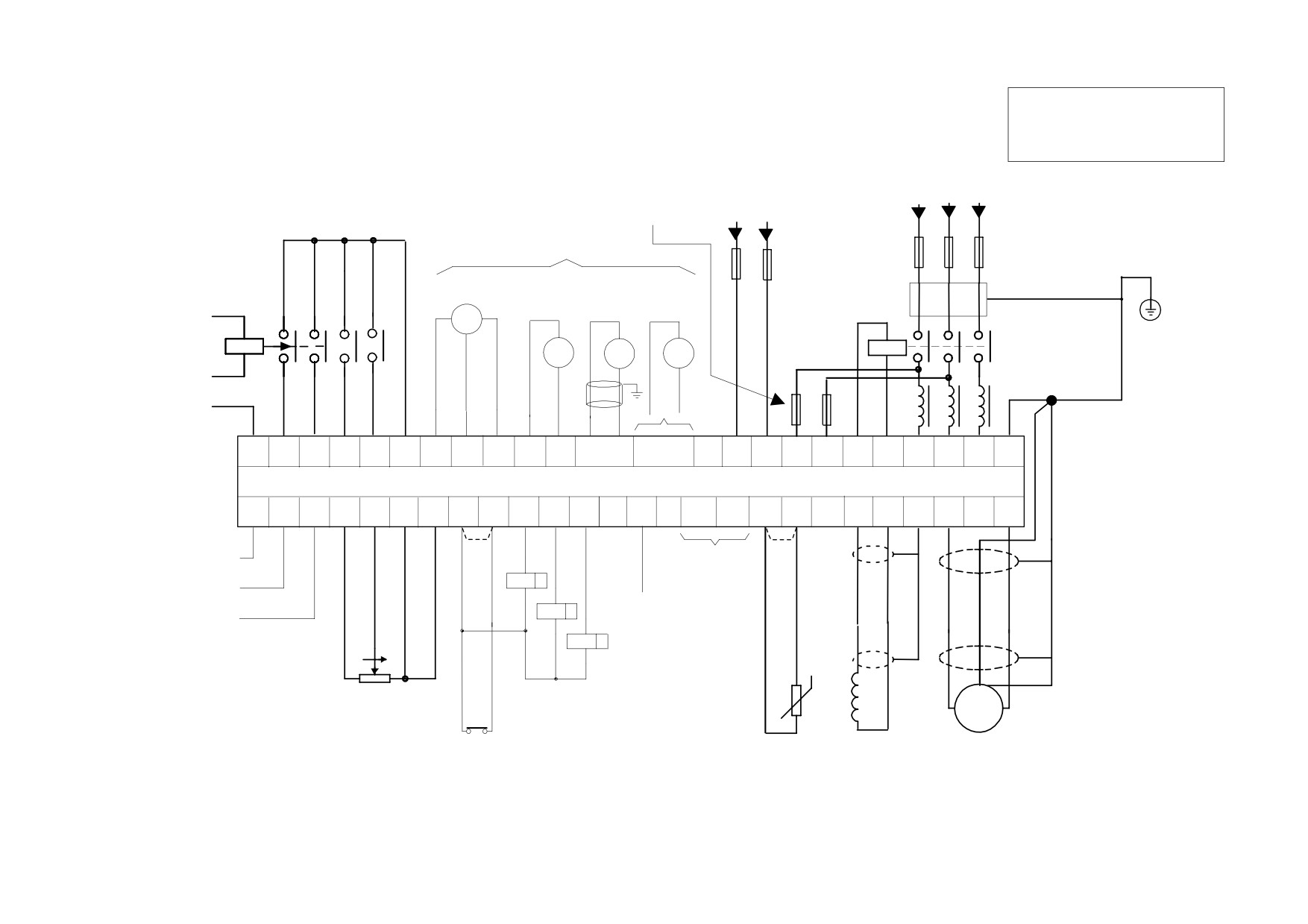
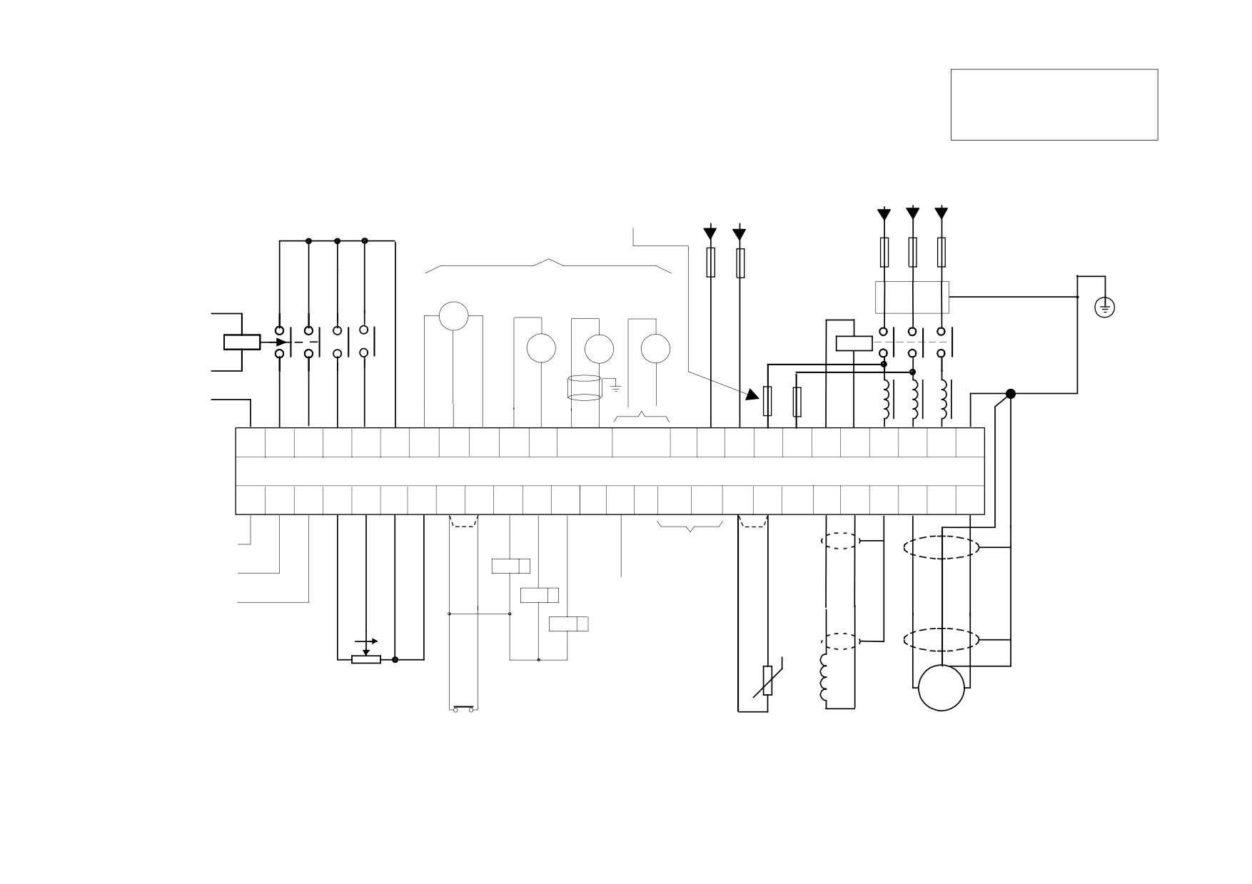
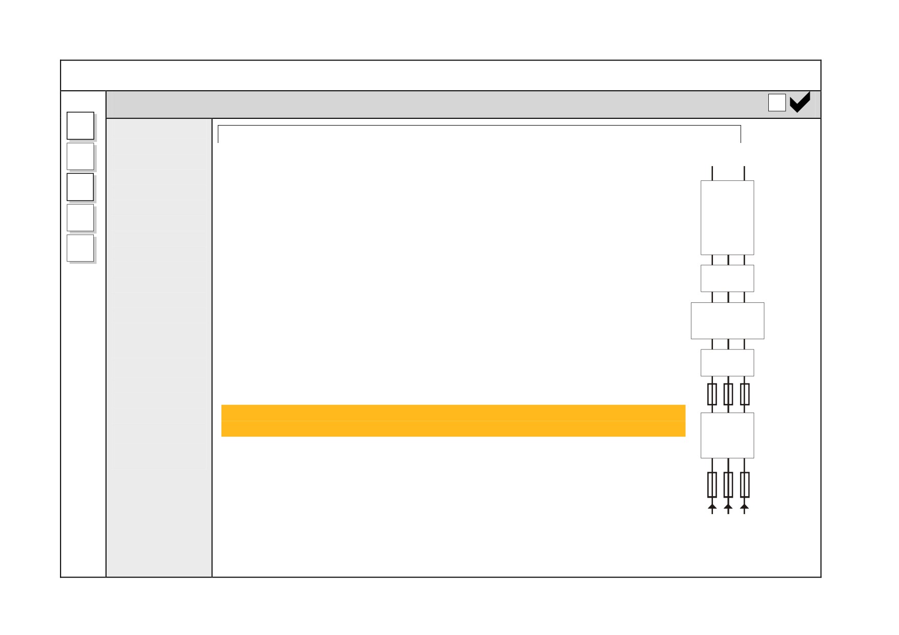
Minimum connections to operate the drive safely are shown using bold lines in the following circuit diagrams. These connections are
highlighted in text with the symbol opposite. The remaining connections are not necessary for a “quick start-up”.
The Drive is using the default Armature Voltage feedback when following the `minimum connection’ instructions.
WARNING
Power terminals carry an electrical voltage which can be lethal. Never work on any control equipment or motors
without first removing all power supplies from the equipment.
Caution
Make sure all wiring connections meet or exceed applicable local and National Electrical Codes. Be sure to fit branch circuit
and motor overload protection.
IMPORTANT
If fitting your own "Power On" indicator lamp, annunciator, etc., this should be switched by an auxiliary contactor of the
main contactor, not by the controller auxiliary relay.
To avoid damaging the drive NEVER carry out high voltage resistance or dielectric strength tests without first completely disconnecting the
drive from the circuit being tested.
3-12 Installing the Drive
Power Cables
NOTE Refer to Appendix E: “Technical Specifications” - Wire Sizes and Termination Tightening Torques.
• minimum rating of 1.1 x full load current (Europe)
• minimum rating of 1.25 x full load current (UL)
Control Wiring
NOTE Refer to Appendix E: “Technical Specifications” for Control Terminal information.
• Control wiring must have a minimum cross-section area of 0.75mm2 (18AWG).
• Use screened control cables to comply with EMC requirements.
• Feed the control cables into the drive and connect to the control terminals. Refer to the connection label on the inside of the terminal cover. Close
the terminal cover.
IMPORTANT All connections made to terminal blocks A, B and C must be isolated signal voltages.
Important Connections
The following connections must be made for the drive to run:
• Terminals TH1 and TH2 must be linked if a motor thermostat is not fitted.
• Terminals C1 and C2 must be linked if an External Trip interlock is not required.
Installing the Drive
3-13
FRAMES 1, 2, 3 & 4
Connection Diagrams
Bold lines indicate
"minimum connections"
AUXILIARY
3-PHASE SUPPLY
SUPPLY
110V - 500VAC (Frames 1,2,3)
110/240VAC
110V - 600VAC (Frame 4)
1 PH 50/60Hz
3 PH 50/60Hz
PROGRAM
START/
3-PHASE
STOP
RUN
COAST
EXTERNAL
Branch
STOP
ENABLE
CONTACTOR
PROTECTIVE
select feedback type
Fuses/
Protection
EARTH
from MMI
Circuit Breaker
Fuses
EXTERNAL
AC FIELD
Filter
(optional)
AC
DC
1 PH 50/60Hz
MICROTACH
ENCODER
TACHO
TACHO
500VAC MAX
High Speed
Frames 2 & 3
Fuses
EMERGENCY
+
600VAC MAX
Frame 4
Start
STOP
CON
Contactor
RELAY
AC Line Choke
SIGNAL 0V
star-point earth
near drive
N
L
FL1
FL2
4
3
C3
C9
C9
F1
C1
G1
G2
G3
G4
E1-6
L1
L2
L3
PE
A1
B9
B8
C5
(D7)
(D8)
(D1)
(D2)
(D6)
(D5)
*use internal
field connection
for EMC compliance
TH1
TH2
F-
F+
A2
A3
A8
B4
A4
B3
A6
C1
C2
B5
B6
B7
H1-6
PE
A-
A+
THERM+
THERM-
(D3)
(D4)
#
#
SPEED SETPOINT No.1 *
SPEED SETPOINT No.2/ *
RL
S
CURRENT DEMAND
RL
S
TOTAL SETPOINT
RL S
RS485 LINK
Additional Speed
TECHNOLOGY
Setpoint Inputs
BOX
ZERO
DRIVE
10K
PE
SPEED
READY
SETPOINT
M
RAMP
DRIVE
+
+
INPUT
HEALTHY
EXTERNAL
MOTOR
MOTOR
FIELD OUTPUT
TRIP
DC
ARMATURE
THERMISTOR
(isolated)
# Links required if Thermistor and/or External Trip switch not fitted
Figure 3- 8 Power Connections: Frames 1, 2, 3 & 4 (`general purpose’ configuration)
3-14 Installing the Drive
3-PHASE SUPPLY
110V - 600VAC
3 PH 50/60Hz
FRAME 5
Bold lines indicate
BRANCH PROTECTION
"minimum connections"
AUXILIARY
SUPPLY
Filter Assemblies (optional)
110/240VAC
1 PH 50/60Hz
Fuses/
Circuit Breaker
EXTERNAL
AC FIELD
Semiconductor
Fuses
600VAC MAX
Pilot
1 PH 50/60Hz
Relay
Master Start
Slave Start
MASTER SLAVE
CON
Contactor
Contactor
star-point earth
Notes:
near drive
a)
You must use two identical line chokes
AC Line Chokes
to guarantee sharing of motor current
N
L
FL1
FL2
4
3
L1
L2
L3
L1
L2
L3
b)
One or two Start Contactors can be used
(D7)
(D8)
(D1)
(D2)
(D6)
(D5)
M
M
M
S
S
S
PE
PROTECTIVE
EARTH
*
c)
Use separate semiconductor fuses
for Master and Slave
TH1
*use internal
TH2
F-
F+
A+
A+
A-
A-
field connection
THERM+
THERM-
(D4)
(D3)
PE
M
M
S
S
for EMC compliance
d)
L1M, L2M & L3M are the Master AC Input Busbars
#
L1S, L2S & L3S are the Slave AC Input Busbars
There are two A+M Master DC Output Busbars
There are two A-S Slave DC Output Busbars
e)
Use both of the A+M terminals, and also both A-S terminals
PE connections MUST be made to both the Master
MASTER SLAVE
f)
and Slave drives
g)
A single dc contactor can be fitted but MUST be used
PE
with an interlock to enable input C5
M
+
+
MOTOR
FIELD OUTPUT
MOTOR
THERMISTOR
DC
ARMATURE
(isolated)
Figure 3- 9 Power Connections: Frame 5
(`general purpose’ configuration)
Installing the Drive
3-15
FRAME 6
Bold lines indicate
"minimum connections"
AUXILIARY
3-PHASE SUPPLY
500V - 690VAC
SUPPLY
PROGRAM
115/230VAC
3 PH 50/60Hz
START/
STOP
Semi-conductor
RUN
1 PH 50/60Hz
COAST
Fuses
STOP
ENABLE
select feedback type
Branch
from MMI
Protection
PROTECTIVE
Fuses/
Fuses
EARTH
Circuit Breaker
AC
DC
MICROTACH
ENCODER
Filter
(optional)
TACHO
TACHO
EXTERNAL
EMERGENCY
+
AC FIELD
3-Phase
690VAC MAX
External
STOP
CON
RELAY
1 PH 50/60Hz
Contactor
AC Line Choke
SIGNAL 0V
star-point earth
near drive
N
C
A1
B9
B8
C5
C3
C9
C9
F1
C1
G1
G2
G3
G4
E1-6
N
L
FL1
FL2
L1
L2
L3
PE
(4)
(3)
TH1
TH2
A2
A3
A8
B4
A4
B3
A6
C1
C2
B5
B6
B7
H1-6
MA+
MA-
F-
F+
PE
A-
A+
THERM+
THERM-
#
Refer to
#
SPEED SETPOINT No.1
"DC
SPEED SETPOINT No.2/ *
RL
S
Contactor -
CURRENT DEMAND
External VA
RS485 LINK
Sensing"
RL
S
TOTAL SETPOINT
TECHNOLOGY
BOX
RL
S
* Additional Speed
Setpoint Inputs
ZERO
DRIVE
10K
PE
SPEED
READY
SETPOINT
M
Note: We recommend that the
RAMP
DRIVE
+
+
INPUT
HEALTHY
MA+ and MA- terminals are
EXTERNAL
MOTOR
FIELD OUTPUT
MOTOR
used in ALL Frame 6 Field
TRIP
THERMISTOR
ARMATURE
Weakening applications, not
(isolated)
DC
just those applications
# Links required if Thermistor and/or External Trip switch not fitted
involving an external DC
Figure 3- 10 Power Connections: Frame 6 (`general purpose’ configuration)
contactor.
3-16 Installing the Drive
FRAME H
Bold lines indicate
"minimum connections"
AUXILIARY
3-PHASE SUPPLY
SUPPLY
110V - 690VAC
110/240VAC
3 PH 50/60Hz
PROGRAM START/
Semi-conductor
1 PH 50/60Hz
STOP
RUN
COAST
Fuses
STOP
ENABLE
select feedback type
Branch
from MMI
Protection
PROTECTIVE
Fuses/
Fuses
EARTH
Circuit Breaker
AC
DC
MICROTACH
ENCODER
Filter
(optional)
TACHO
TACHO
EXTERNAL
EMERGENCY
AC FIELD
+
3-Phase
STOP
690VAC MAX
CON
External
RELAY
1 PH 50/60Hz
Contactor
AC Line Choke
SIGNAL 0V
star-point earth
near drive
N
C
C3
C9
C9
F1
C1
G1
G2
G3
G4
E1-6
N
L
FL1
FL2
L1
L2
L3
PE
A1
B9
B8
C5
(4)
(3)
TH1
TH2
A2
A3
A8
B4
A4
B3
A6
C1
C2
B5
B6
B7
H1-6
MVA+
MVA-
F-
F+
PE
A-
A+
THERM+
THERM-
#
Refer to
#
SPEED SETPOINT No.1 *
"DC
SPEED SETPOINT No.2/ *
RL
S
Contactor -
CURRENT DEMAND
External VA
RS485 LINK
Sensing"
RL
S
TOTAL SETPOINT
TECHNOLOGY
BOX
RL
S
* Additional Speed
Setpoint Inputs
ZERO
DRIVE
10K
PE
SPEED
READY
SETPOINT
M
RAMP
DRIVE
+
+
INPUT
HEALTHY
EXTERNAL
MOTOR
FIELD OUTPUT
MOTOR
TRIP
ARMATURE
THERMISTOR
DC
(isolated)
# Links required if Thermistor and/or External Trip switch not fitted
Figure 3- 11 Power Connections: Frame H (`general purpose’ configuration)
Installing the Drive
3-17
Power Connections
3-Phase Supply, 3-Phase External Contactor
L1
Connect the
Frame 3: Terminals 3 & 4 = D5 & D6 : Frame H & Frame 6: Terminals 3 & 4 = C & N
main ac
L2
power to
Main AC Power
busbar
There is no specific phase connection to terminals L1, L2 and L3 as the controller is
L3
terminals L1,
phase rotation independent.
DC
L2 & L3 via
DRIVE
Branch Protection
3
the Branch
AC current = 0.83 x DC Armature Current
Protection,
4
AC Filter
You must provide branch circuit protection using a suitable fuse or Type 2 circuit breaker
(optional),
(RCD, ELCB, GFCI circuit breakers are not recommended, refer to “Earth Fault
CHOKE
3-Phase
Monitoring Systems”, page 3-62). Also refer to Appendix B: “Certification” - Conditions
External
for Compliance with UL508c.
590AC LINE
Contactor,
CHOKE FILTER
and AC Line
Semi-Conductor Protection
CO468398
Choke.
Frame H drives contain high speed semi-conductor fuses. For all other frame sizes,
always provide high-speed thyristor fusing to protect the thyristor stack in the case of
CON
Connect the
direct output short circuits. Semiconductor fuses may be used as Branch Protection on
contactor coil
single-drive systems.
Semiconductor
Fuses
to terminals 3
(Line) and 4
IMPORTANT If a motor becomes completely short-circuited, the current trip
(OVER I TRIP) will not protect the Drive.
FILTER
(Neutral).
(optional)
Refer to Appendix E: “Technical Specifications” - External Power Semiconductor
Protection Fuses.
Branch
Protection
Fuses
AC Filter (optional)
Refer to "External AC Supply EMC Filter Installation", page 3-60.
Diagram shows
correct
placement
of units
3-18 Installing the Drive
Power Connections continued
3-Phase Supply, 3-Phase External Contactor continued
3-Phase External Contactor
The contactor does not switch current and is primarily for disconnection and sequencing of the power bridge. It
must be energised directly from the controller by a coil with a rating suitable (AC1) for the controller concerned. No
additional series contacts or switches are permitted since they will interfere with the sequencing of the controller
and cause unreliability and possible failure.
Connect to main contactor terminals Con L and Con N only as described in Appendix E, otherwise
unreliable or dangerous operation may occur - do not connect to a PLC input or sensitive relay.
Slave Relay : If the 3-phase contactor has a coil with an inrush greater than 3A, a slave relay MUST be used to
drive the contactor coil. The contactor and slave relay (if required) MUST have coil voltages compatible with the
controller auxiliary supply voltage.
DO NOT use a slave relay with a coil current less than 25mA as it may be energised by the contact
suppression network.
Frames 4 & 5 : A relay jumper (CONN1) is provided on the power board enabling terminals 3 & 4 to be powered
(auxiliary supply - default position), or to be volt-free (for customers own contactor supply). Refer to
"AH466701U001, U002, U003 (Frames 4 & 5)", page 3-46.
DC Contactor : A DC contactor can be used but the sequencing must be adjusted to accommodate its use: an
auxilliary normally open volt-free contact of the contactor must be connected in series with the "ENABLE" input
(C5) to disable the drive until after the contactor is closed.
AC Line Choke
IMPORTANT Always fit the recommended choke. Refer to Appendix E: “Technical Specifications” - AC
Line Choke.
We can provide suitable chokes, designed to connect directly to the drive terminals. Refer to Appendix E:
"Technical Specifications" - AC Line Choke.
Installing the Drive
3-19
Power Connections continued
PE
Protective Earth Connections
Connect the
IMPORTANT The drive and filter (if fitted) must be permanently earthed. Each conductor used for
drive's PE
permanent earthing must individually meet the requirements for a protective earth
terminal to an
conductor.
independent
For installations to EN 60204 in Europe:
earth/ground
• For permanent earthing, the drive requires either two individual incoming protective earth conductors (<10mm²
star point.
cross-section), or one conductor (≥10mm² cross-section) connected to an independent protective earth/ground
Connect this
point near the drive.
earth/ground
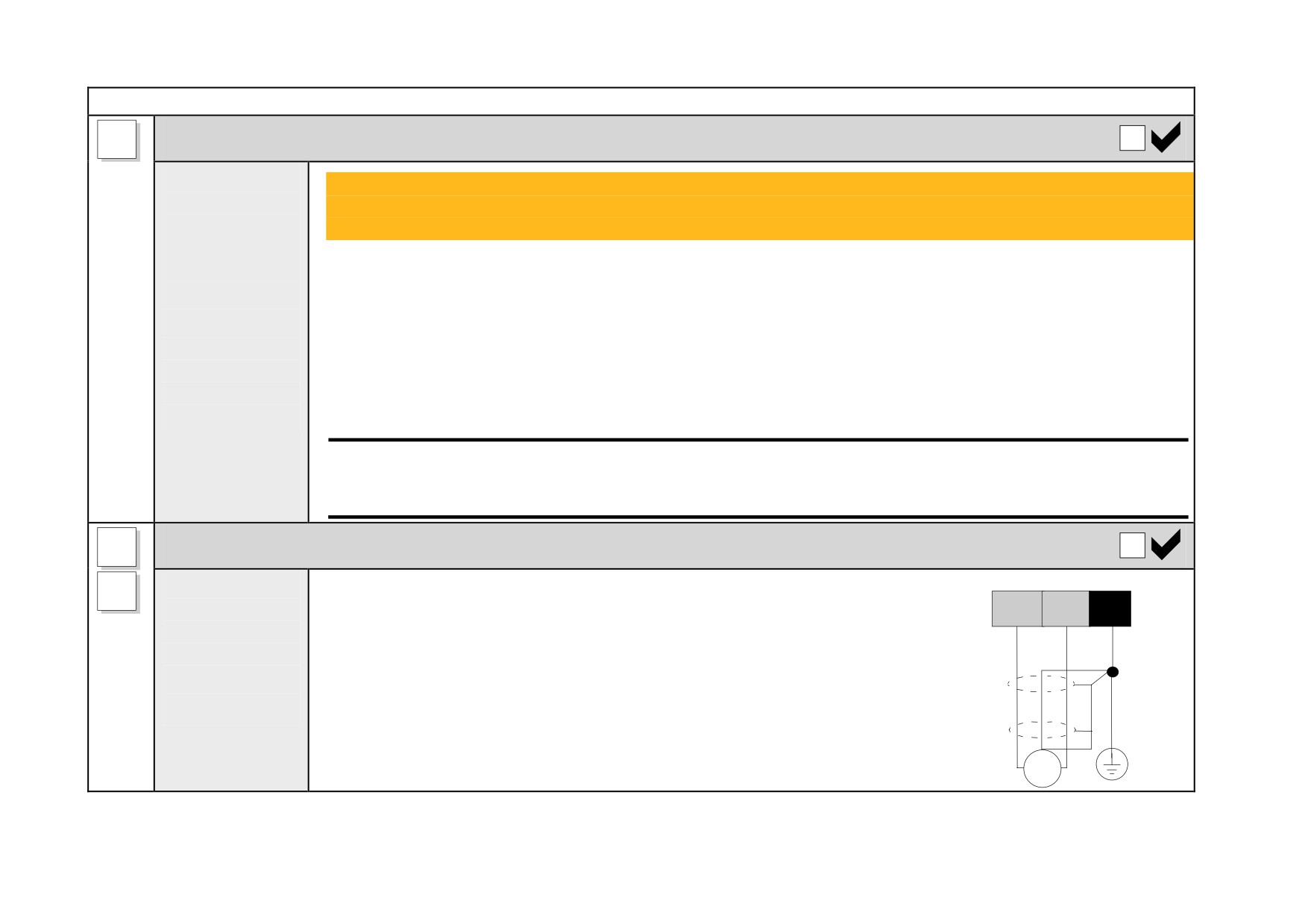
• Run the motor protective earth/ground connection in parallel with the motor supply conductors, ideally in the
star point to
same conduit/screen/armour, and connect to an independent protective earth/ground point near the drive.
Protective
Refer to Appendix B: “Certification” - EMC General Installation Considerations.
Earth.
Caution
On the Frame 5, both the Master and Slave drives must be individually earthed.
A+
Motor Armature
Connect the
Connect the cable screen to the motor's PE terminal and the earth/ground star point.
A-
motor
Connect the motor's PE terminal to the earth/ground star point.
A+
PE
A-
armature to
For cable information refer to Appendix B: "Certification" - Recommended Wire Sizes.
star
terminals A+
point
and A-.
NOTE If the drive is to operate in regenerating mode for long periods, it is
advisable to fit a dc fuse or high speed circuit breaker in the armature
circuit. If in doubt consult Parker SSD Drives.
PE
M
+