Parker 590+ series Frame 1, 2, 3, 4, 5, 6 & H. Product Manual (2012) - page 2
Chapter 2 Product Overview
An introduction to the 590+ range of products, and a quick look at the Keypads and available plug-in Options.
Product Range
• Keypads
How it Works
• Option Boards
Control Features
Product Overview 2-1
Product Range
The DC590+ Series DC Digital Drive is designed for use in a suitable enclosure, with associated control equipment. The unit accepts a variety of
standard three-phase ac supply voltages depending upon the model, and is suitable for the powering of DC shunt field and permanent magnet motors,
providing controlled dc output voltage and current for armature and field.
All units are designed for simple and economical panel mounting using keyhole slots. Plug-in control connectors simplify the fitting and removal of
the unit to the panel.
Where possible, standard parts are used throughout the range thereby reducing the variety of spare parts required to maintain a multi-drive system. For
example, the same basic control boards are used in all types of three-phase armature controller regardless of horsepower or bridge configuration.
The control circuit is totally isolated from the power circuit thus simplifying the interconnection of controllers within a system and improving operator
safety. The coding circuitry adjusts automatically to accept supply frequencies between 45-65Hz and possesses high immunity to supply-borne
interference. The armature controllers are phase rotation insensitive.
Control and Communications
The drive is controlled by a 32 bit Microcontroller providing advanced features such as:
• Complex control algorithms which are not achievable by simple analog techniques.
• Software-configurable control circuitry built around standard software blocks.
• Serial link communications with other drives or a PC for advanced process systems.
The Keypad gives access to parameters, diagnostic messages, trip settings and full application programming.
Regenerative and Non-Regenerative Models
The motor armature controllers include both regenerative and non-regenerative models:
• Regenerative controllers consist of two fully-controlled thyristor bridges and a field bridge with full transient and overload protection, together
with sophisticated electronic control of acceleration and deceleration, speed and torque in both directions of rotation.
• Non-regenerative controllers consist of one fully-controlled thyristor bridge and a field bridge with full transient and overload protection,
together with its associated electronic control circuitry, and provide accurate speed and/or torque control in one selected direction of rotation.
Field Regulator
A field regulator is fitted as standard. The regulator consists of a full-wave half controlled single phase thyristor bridge with transient and overload
protection. It provides either a fixed voltage or fixed current source, depending upon the selected mode of operation for constant torque applications.
The field current mode of operation can be further enhanced to provide field weakening for drive control motors which require extended speed or
constant horsepower control.
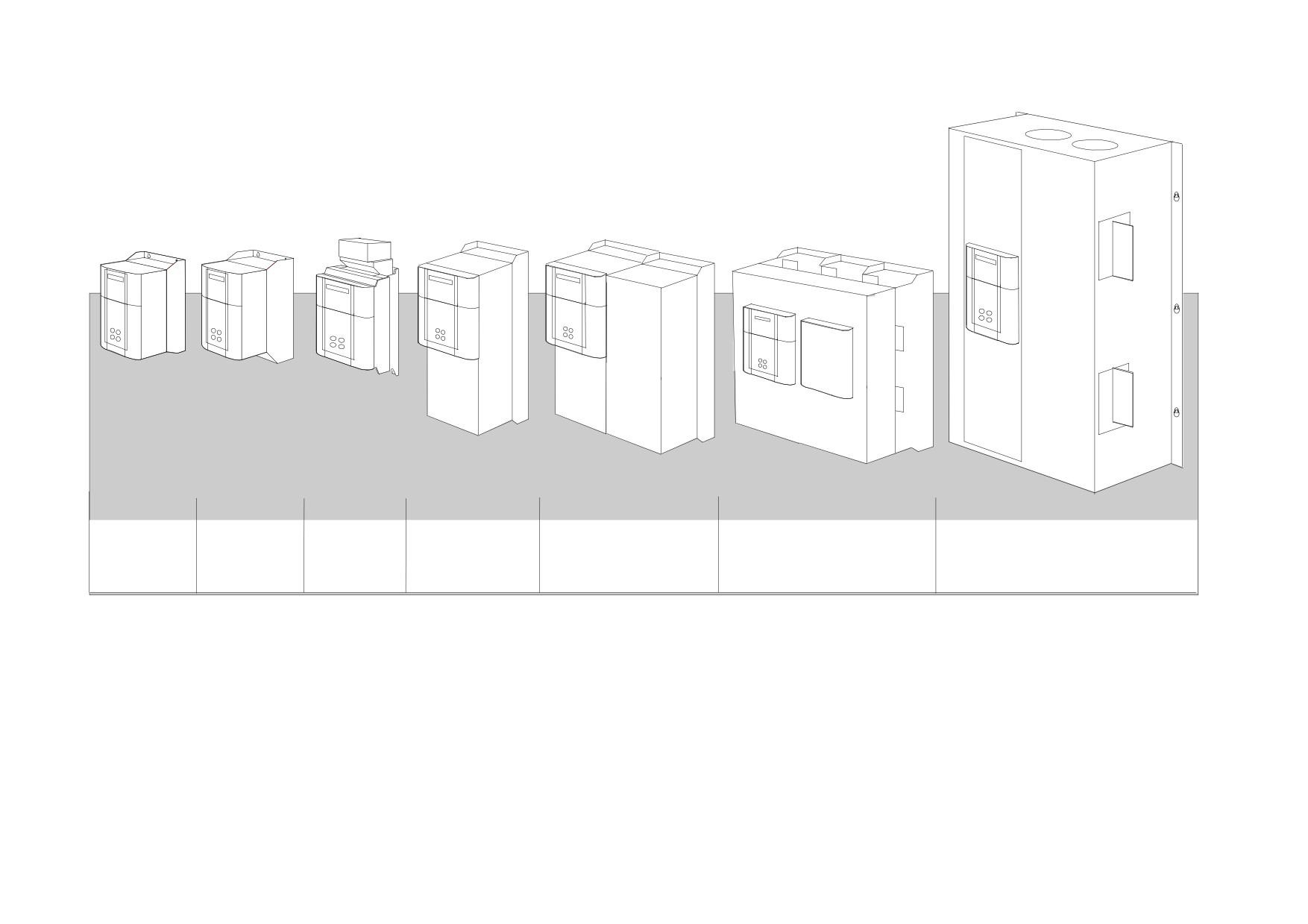
2-2 Product Overview
Output Currents (armature):
Frame 1
Frame 2
Frame 3
Frame 4
Frame 5
Frame 6
Frame H
15A
40A
180A
380A
1580A
1250A
1200A
35A
70A
270A
500A
1600A
1700A
110A
725A
1950A
2200A
165A
830A
2700A
All units are available as a:
590+ :
4Q 3-phase, fully controlled, anti-parallel thyristor bridge configuration
591+ :
2Q 3-phase, fully controlled thyristor bridge configuration
Product Overview 2-3
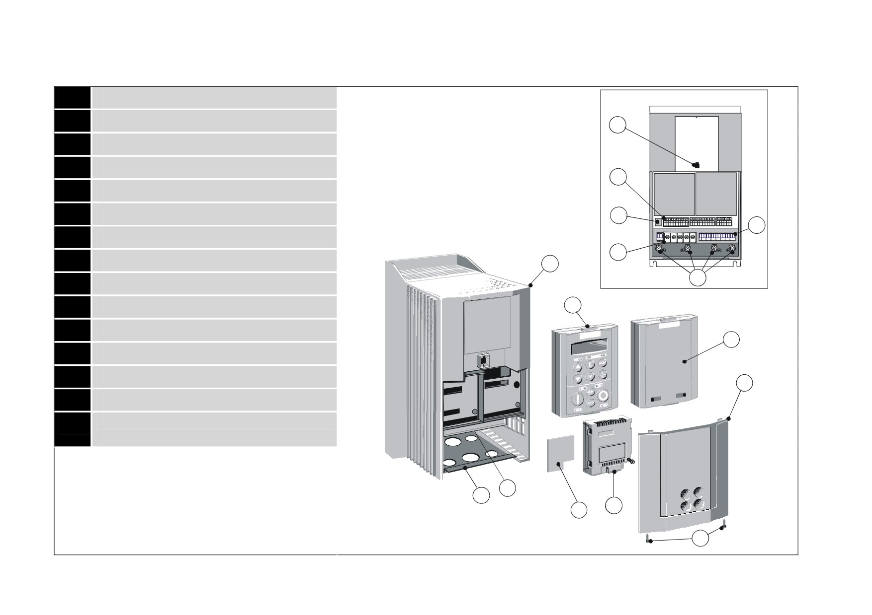
590+ Controller (Frames 1 & 2)
1
Main drive assembly
Front View (with items
2
Terminal cover
13
3
Terminal cover retaining screw
4
Blank cover
11
5
6901 keypad (optional)
6
COMMS technology box (optional)
14
15
7
Speed feedback technology card (optional)
10
8
Gland plate
1
12
9
Power terminal shield
10
Power terminals
5
11
Control terminals
4
12
Earthing points
13
Keypad port
2
14
RS232 programming port
15
Auxiliary power, external contactor and isolated
thermistor terminals
9
8
6
7
3
Frame 1, 15A unit illustrated
2-4 Product Overview
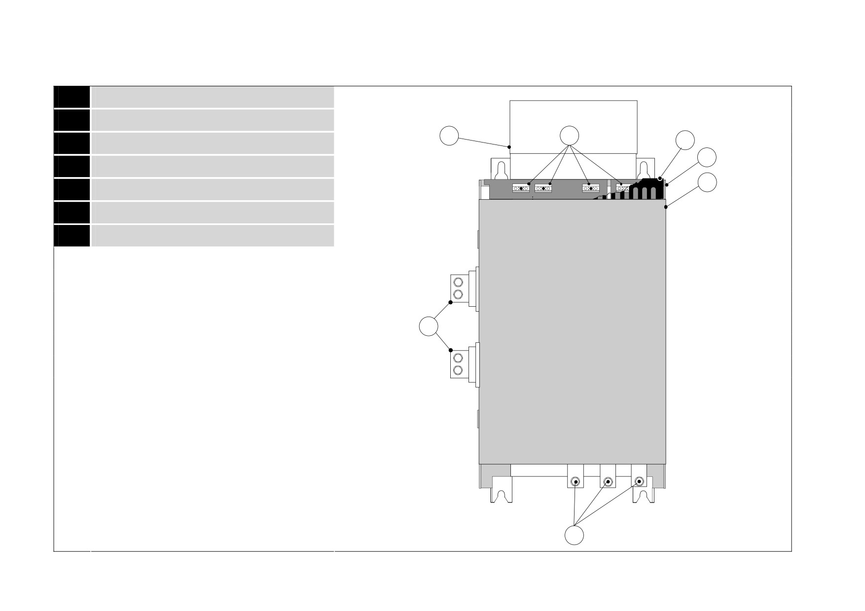
590+ Controller (Frame 3)
1
Main drive assembly
2
Door assembly
7
3
6
3
Field wiring terminals
1
4
Busbars - main power input
2
5
Busbars - main power output
6
IP20 Top Cover
7
IP20 Fan Housing (where fitted)
A+
Door
Assembly
5
Product Code 590PXD/
A-
L1
L2
L3
4
270A unit illustrated
Product Overview 2-5
590+ Controller (Frames 4 & 5)
Frame 4
Frame 5
1
Main drive assembly
2
Standard door assembly
3
Motor field terminals
7
9
4
Busbars - main power input
5
Busbars - main power output
1
6
Auxiliary supply, contactor and motor thermistor
2
terminals
10
7
Frame 4 External vent (where fitted)
8
Contactor Control Select
Door
6
Assembly
9
Frame 5 External vent (where fitted)
Product Code 590PD/
10
Terminal Cover (Frame 5)
8
3
field & auxiliary
connections
via grommet
4
Frame 4
Frame 5
L1
L2
L3
L1
L2
L3
On the Frame 5,
5
both the Master and Slave drives must be individually
earthed
A+
A-
A-
A-
When Frame 5, both terminals are for A+ connections
2-6 Product Overview
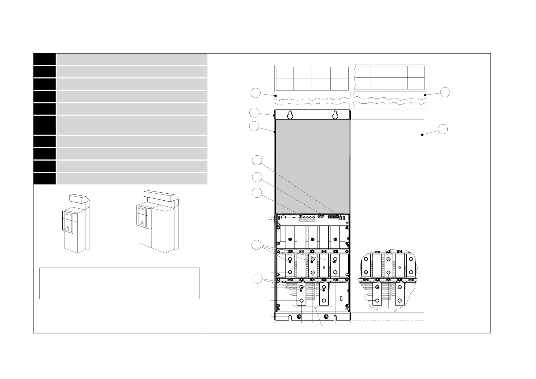
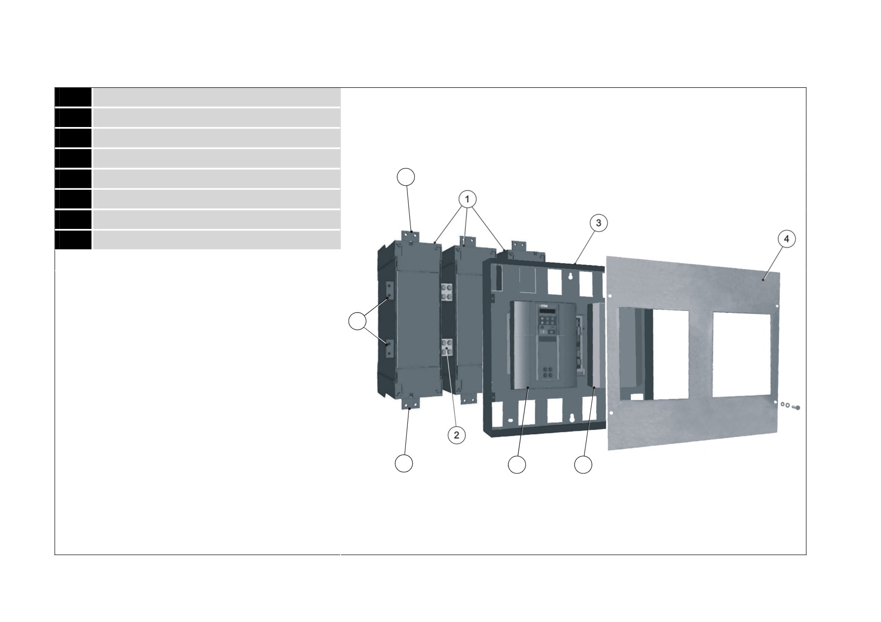
590+ Controller (Frame 6)
1
Phase assemblies - L1, L2, L3
2
Fishplate
3
Control Panel Assembly
4
Front Cover
5
Standard Door Assembly
7
6
Field Controller
7
Busbars - main power input
8
Busbars - main power output
8
7
5
6
Product Overview 2-7
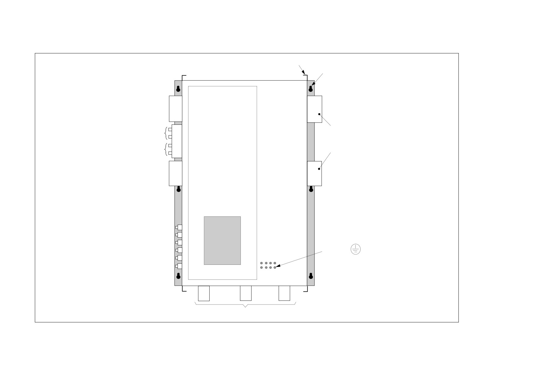
590+ Product (Frame H)
Removable Lifting Brackets
(4 off)
Keyhole Mounting Slots
(8 off for 4Q Regenerative)
(6 off for 2Q Non-Regenerative)
590+
SERIES
A-
Armature terminals are
Auxiliary
L
Power
fitted to right hand side
Power
Control
N
of the drive but can
Terminals
Main
be moved to the left
N
Contactor
hand side if necessary
Coil
MC
A+
FL1
Door
Motor field
Assembly
supply and
FL2
and output
F+
Product Code
terminals plus
590PXD/
F-
Earth/PE
external armature
(On the Back
voltage sense
MVA+
of the Converter)
MVA-
L1
L2
L3
Mains Supply Terminals
2-8 Product Overview
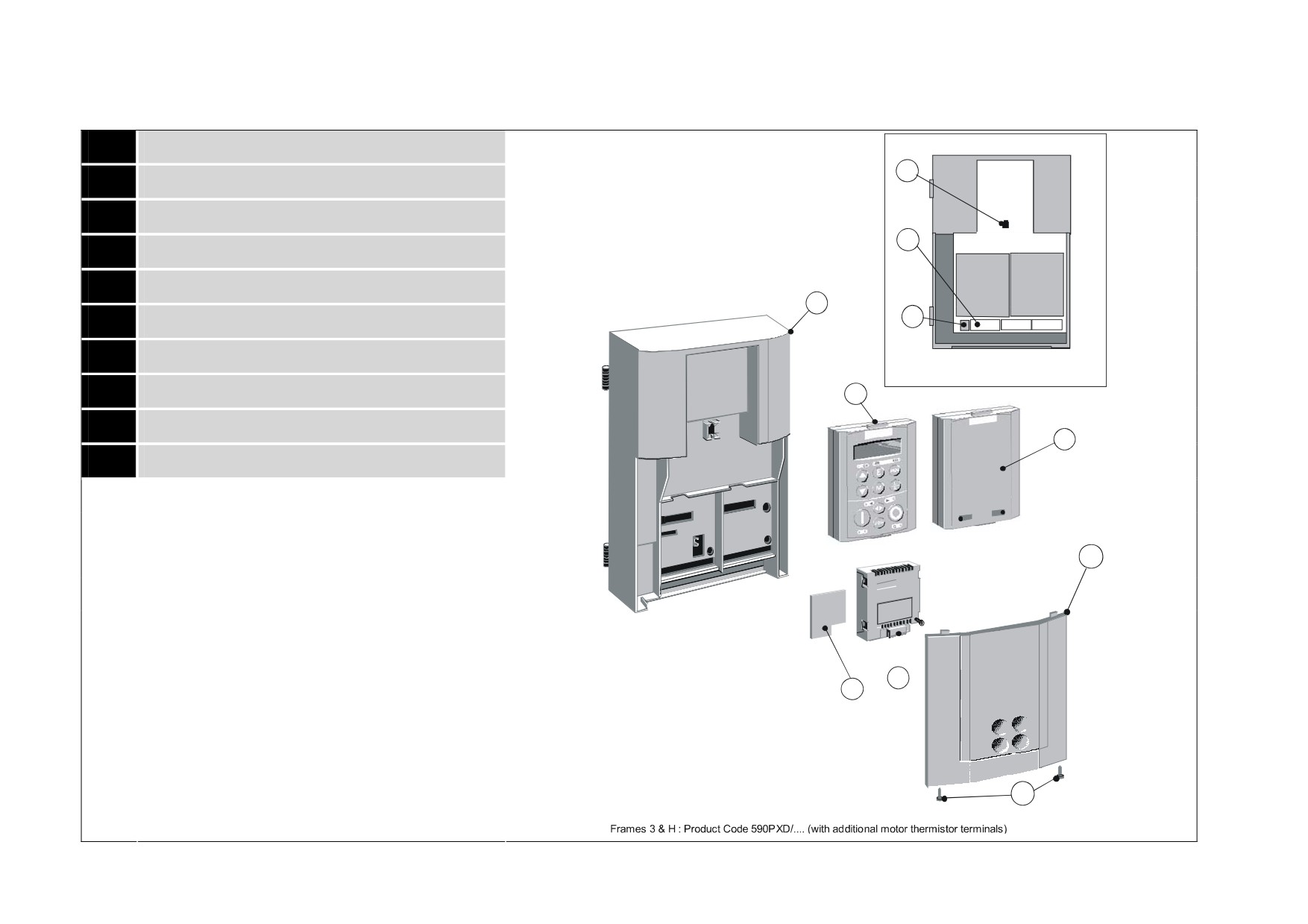
590+ Door Assembly (Frames 3, 4, 5, 6 & H)
1
Main door assembly
Front View (with items removed)
9
2
Terminal cover
3
Terminal cover retaining screw
8
4
Blank cover
5
6901 keypad (optional)
1
10
6
COMMS technology box (optional)
7
Speed feedback technology card (optional)
8
Control terminals
5
9
Keypad port
4
10
RS232 programming port (P3)
2
6
7
3
Frames 4 & 5 : Product Code 590PD/
(illustrated)
Product Overview 2-9
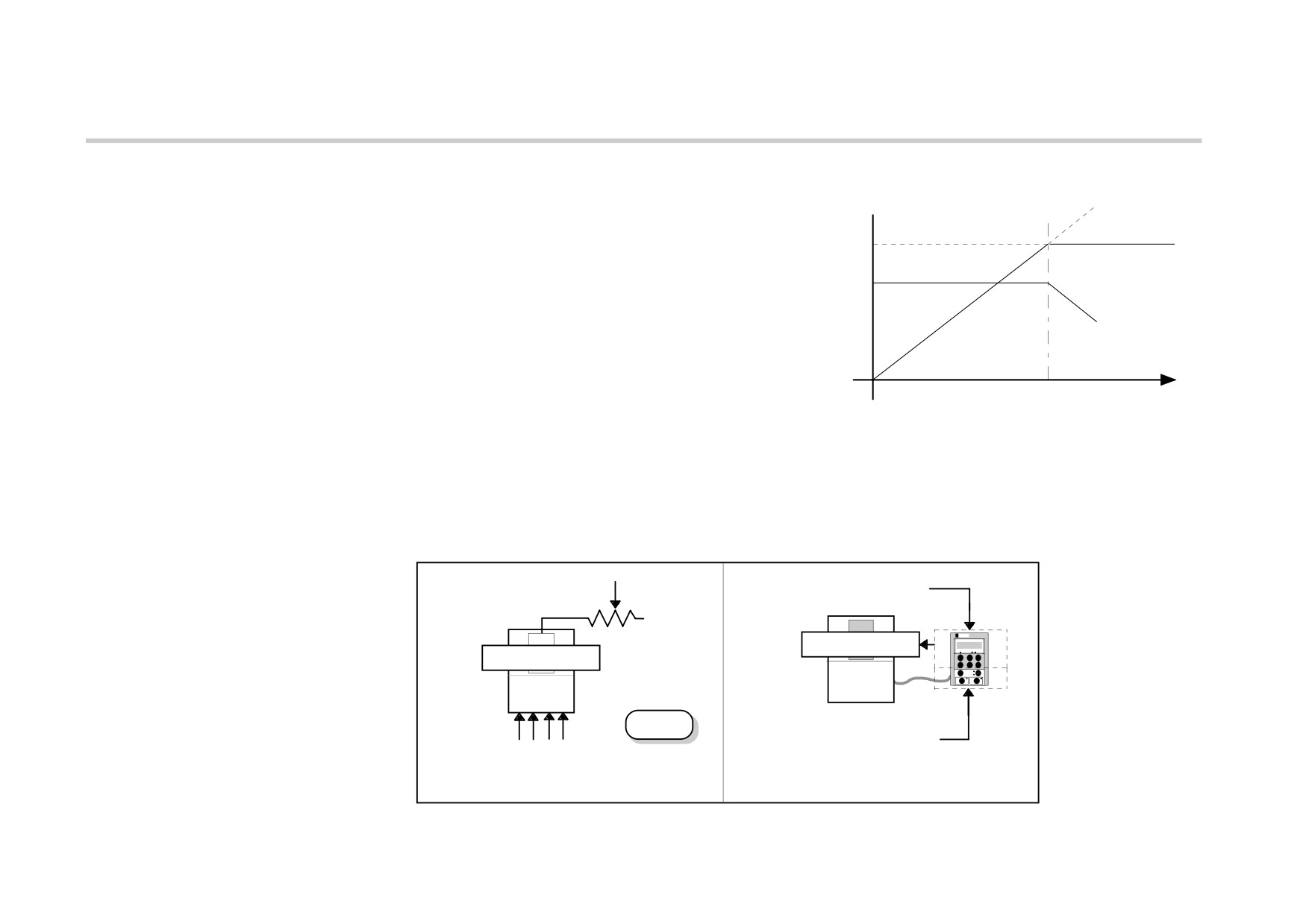
How it Works
NOTE
Refer to Chapter 5: “Control Loops” for a more detailed explanation.
In very simple terms, the drive controls the dc motor with the use of
speed increase
Control Loops - an inner Current Loop and an outer Speed Loop. These
due to field
control loops can be seen in the Application Block Diagram. The block
weakening
Armature
diagram shows all the drive's software connections.
Voltage 200V
armature voltage
Using the Keypad, you can select the control loops to be used by the
remains constant
Field Current 5.7A
drive to provide either:
• Current Control
field current
reduced
• Speed Control (default)
It is usual to supply a Current or Speed Feedback signal to the
base
appropriate loop for more effective control of the drive. Current
Speed
speed
Feedback sensors are built-in, whereas Speed Feedback is provided
directly from the armature sensing circuit (default), or by tachogenerator, encoder or Microtach connection to the relevant option board.
When in Speed Control, you can modify the performance of the drive further by controlling the motor field, i.e. Field Control. By weakening the field
current, you can obtain an increase in motor speed beyond that normally achievable for the rated Armature Voltage of the dc motor.
The drive is controlled remotely using digital/analog inputs and outputs, or locally using the Keypad. By plugging in a COMMS Option Technology
Box, the drive can be linked into a network and controlled by a PLC/SCADA or other intelligent device.
REMOTE
LOCAL
SPEED CONTROL
SPEED CONTROL
SPEED SETPOINT
SPEED SETPOINT
DEFAULT
LOCAL START/STOP
REMOTE START/STOP
REMOTE CONTROL
LOCAL CONTROL
2-10 Product Overview
Control Features
Control
Control Circuits
Fully isolated from power circuit (SELV)
Output Control
• Fully controlled 3-phase thyristor bridge
• Microprocessor implemented phase control extended firing range
• For use on 50 or 60Hz supplies with a frequency compliance range of 45 to 65Hz
• Phase control circuits are phase rotation insensitive
Control Action
• Fully digital
• Advanced PI with fully adaptive current loops for optimum dynamic performance
• Self Tuning Current Loop utilising "Autotune" algorithm
• Adjustable speed PI with integral defeat
Speed Control
• By Armature Voltage feedback with IR compensation
• By Encoder feedback or analog tachogenerator
Speed Range
100 to 1 typical with tachogenerator feedback
Steady State Accuracy
•
0.01 % Encoder Feedback with Digital setpoint (serial link or P3)
•
0.1 % Analog Tach Feedback
•
2 % Voltage Feedback
•
Absolute (0.0% error) using QUADRALOC Mk II 5720 Digital Controller
NOTE Long term analog accuracy is subject to tachogenerator temperature stability.
Adjustments
All adjustments in software can be altered by
the Keypad or via serial communications. The Keypad provides monitoring and adjustment of parameters and levels,
in addition to diagnostic facilities.
Protection
• High energy MOVs
• Thyristor Stack overtemperature
• Overcurrent (instantaneous)
• Thyristor "Trigger" failure
• Overcurrent (inverse time)
• Thyristor Snubber Network
• Field failure
• Zero-speed detection
• Speed feedback failure
• Standstill logic
• Motor overtemperature
• Stall protection
Diagnostics
• Fully computerised with first fault latch and automatic display
• Digital LCD monitoring
• Full diagnostic information available on RS422/RS485
• LED circuit state indication
Table 2-1 Control Features
Product Overview 2-11
Keypads
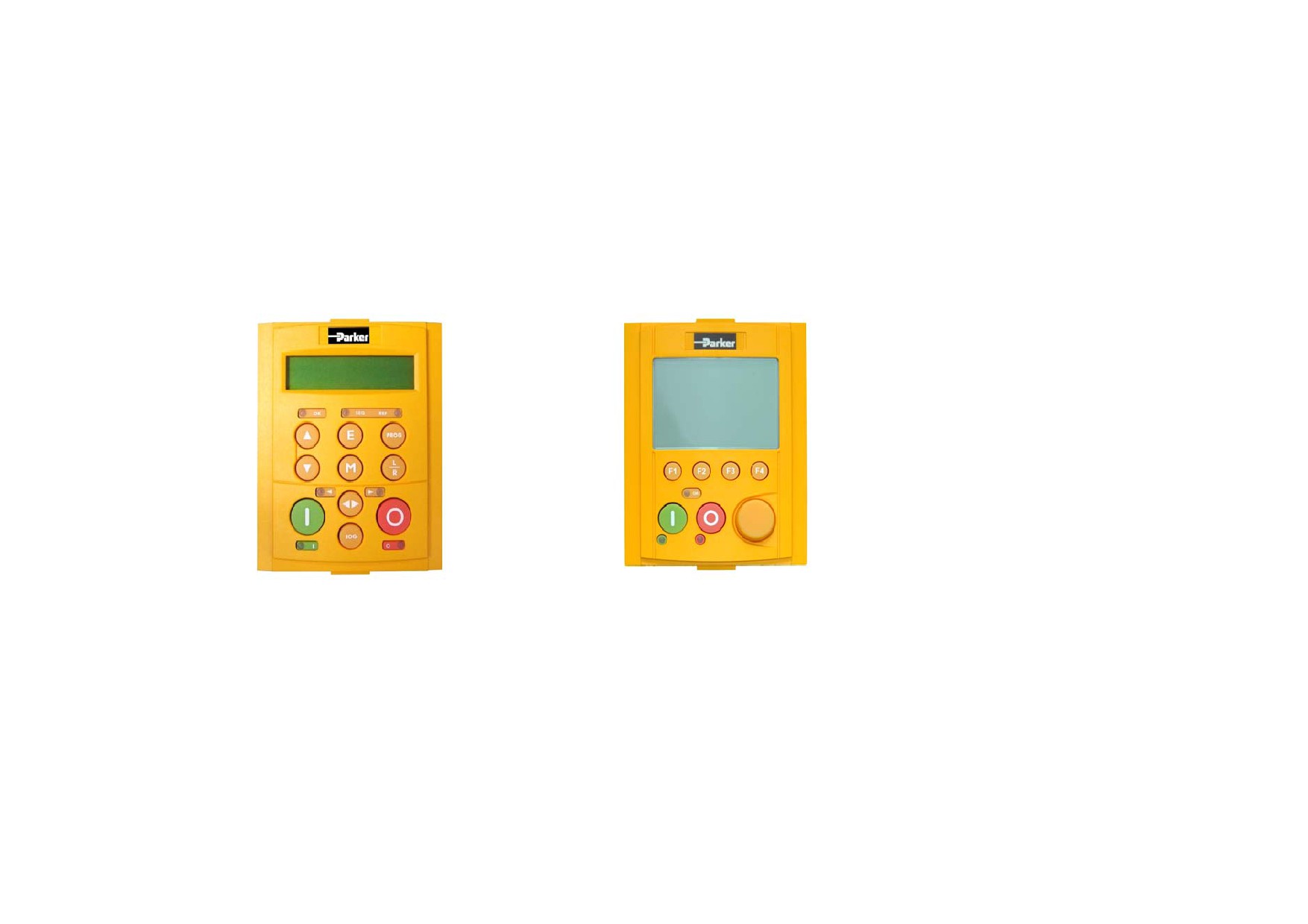
The drive is fitted with the 6901 Keypad.
It provides Local control of the drive, monitoring and complete access for application programming.
For example, you can start and stop the motor, check on diagnostic information, and change parameters values on the drive.
The keypad fits to the front of the drive, however, you can also remote-mount the keypad up to 3 metres away.
Alternatively, you can fit a 6911 keypad. The 6911 provides a larger screen and improved functionality.
For remote-mounting, you’ll need the correct Remote Mounting Kit. Refer to Chapter 6: "The Keypad".
6901 Keypad
6911 Keypad
Option Boards
A range of Option Boards are available for the DC590+ drive. The boards provide for Speed Feedback and Communications.
Refer to Chapter 3 : "Installing the Drive" - Speed Feedback and Technology Options.
Chapter 3 Installing the Drive
This chapter describes the installation of the DC590+ drive and associated equipment.
• Mechanical Installation
•
Drive Installation Drawings
• Unpacking the Drive
•
Filter Installation Drawings
• Lifting the Drive
•
Line Choke Installation Drawings
• Mounting the Drive
• Ventilation and Cooling Requirements
• AC Line Choke
• Filtering
• Electrical Installation
• Minimum Connection Requirements
• Motor Field Options
• DC Contactor - External Va Sensing
• Power Board Circuit Descriptions
• Optional Equipment
• Remote Mounting the Keypad
• Frame 6: Assembly and Installation
• Assembly
• Electrical Installation
• Frame H: Additional Information
• Installation Drawings
Installing the Drive
3-1
Mechanical Installation
IMPORTANT Read Appendix B: “Certification" before installing this unit. Refer to “Installation Drawings”, page 3-75 for further
information. Note the additional information for Frame 6 and Frame H at the end of this Chapter.
Unpacking the Drive
Caution
The packaging is combustible and this action may produce lethal
toxic fumes.
Save the packaging in case of return. Improper packaging can result in transit
damage.
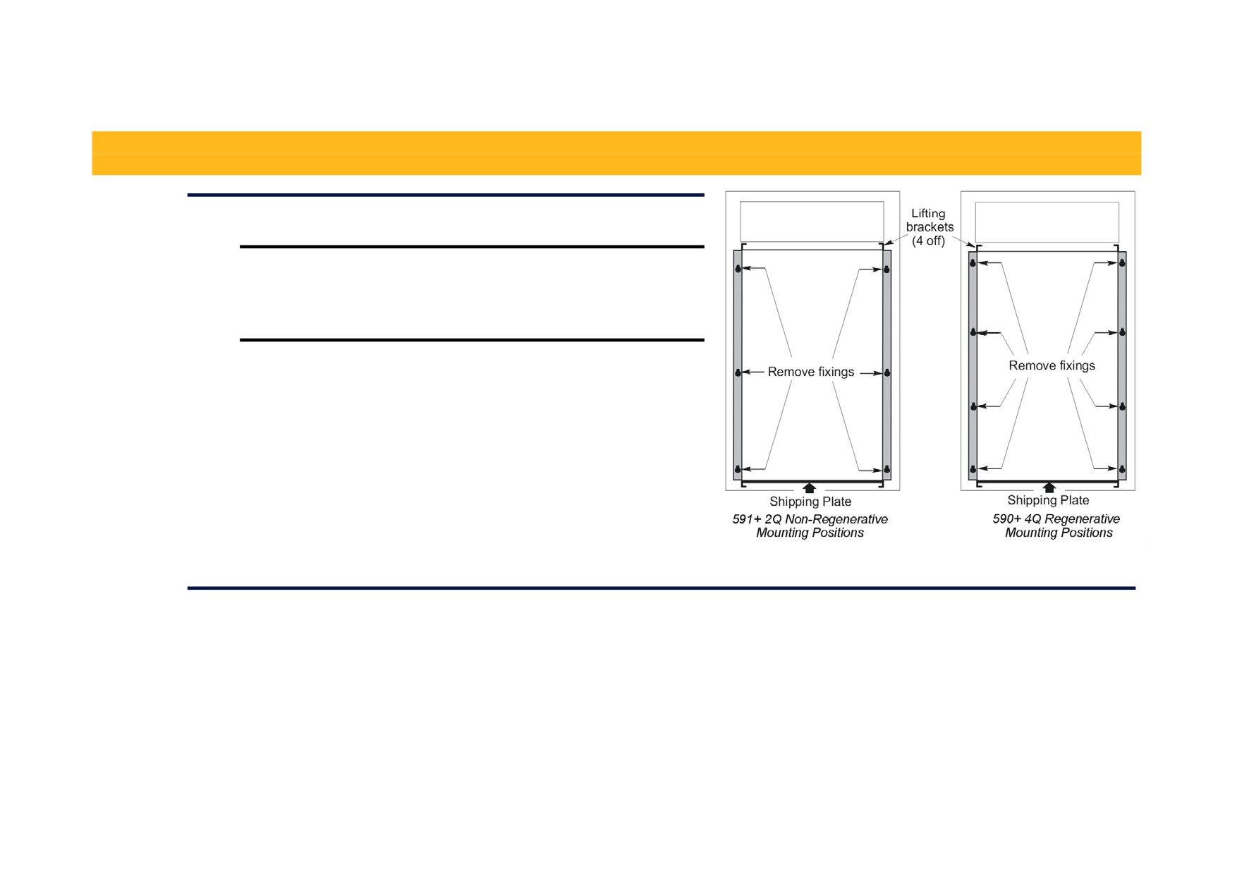
Frame H Packaging
Large drives (Frame H) are supplied in special packaging bolted to a pallet
with removable sides. Remove all fixings from the pallet.
Figure 3- 1 Lifting Details (Frame H)
Lifting the Drive
Use a safe and suitable lifting procedure when moving the drive. Never lift the drive by its terminal connections. Prepare a clear, flat surface to receive
the drive before attempting to move it. Do not damage any terminal connections when putting the drive down.
Frame 4 & 5 drives have lifting eyes and a shipping plate fitted to the base to enable the drive to be lifted into position, or to be set-on-end by a forklift.
Remove the shipping plate before wiring the power terminals.
Frame H drives require the following:
• The drive is supplied with a lifting bracket fitted to each corner for hoisting. Remove the brackets when the drive is in its final position, however,
the bracket fixings MUST be re-fitted. Refer to Appendix E: “Technical Specifications” - Termination Tightening Torques (Frame H).
• A shipping plate is fitted to the base to enable the drive to be set-on-end by a forklift. Remove the plate before wiring the power terminals.
3-2 Installing the Drive
C
D
D
D
E2
C
E2
C
E1
B
E1
B
E1
B
A
A
A
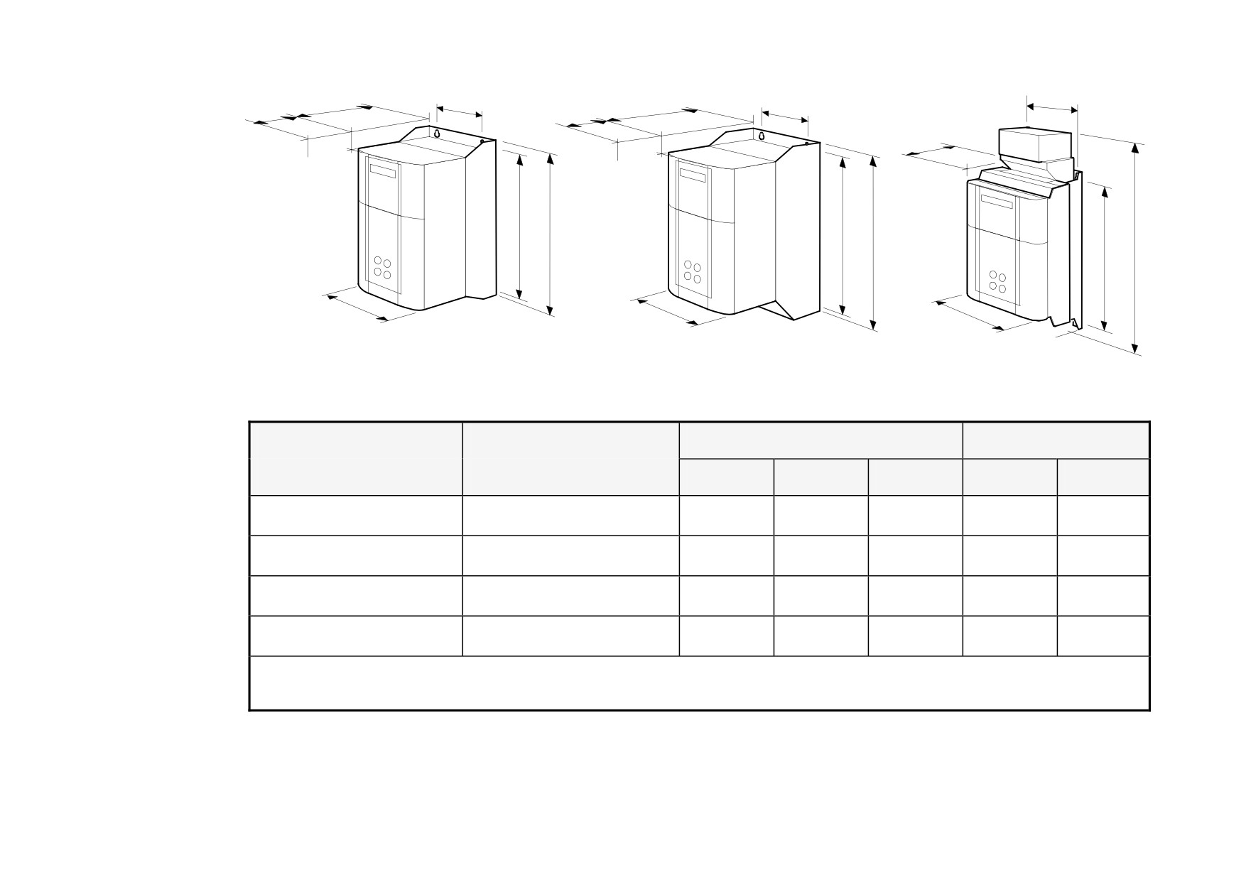
15A - 35A
40A - 165A
180A - 270A
Frame 1
Frame 2
Frame 3
Current Rating (A)
Weight in Kg (lbs)
Overall Dimensions
Fixing Centres
A
B
C
D
E1
15 - 35
6.4 (14)
200 (7.9)
375 (14.8)
220 (8.7)
140 (5.5)
360 (14.2)
40 - 165
10.5 (23)
200 (7.9)
434 (17.1)
292 (11.5)
140 (5.5)
418 (16.5)
180
20 (44)
250 (9.8)
485 (19.1)
234 (9.2)
200 (7.9)
400 (15.7)
270
20 (44)
300 (11.8)
485 (19.1)
234 (9.2)
200 (7.9)
400 (15.7)
Dimensions are in millimetres (inches)
Refer to “Installation Drawings”, page 3-75.
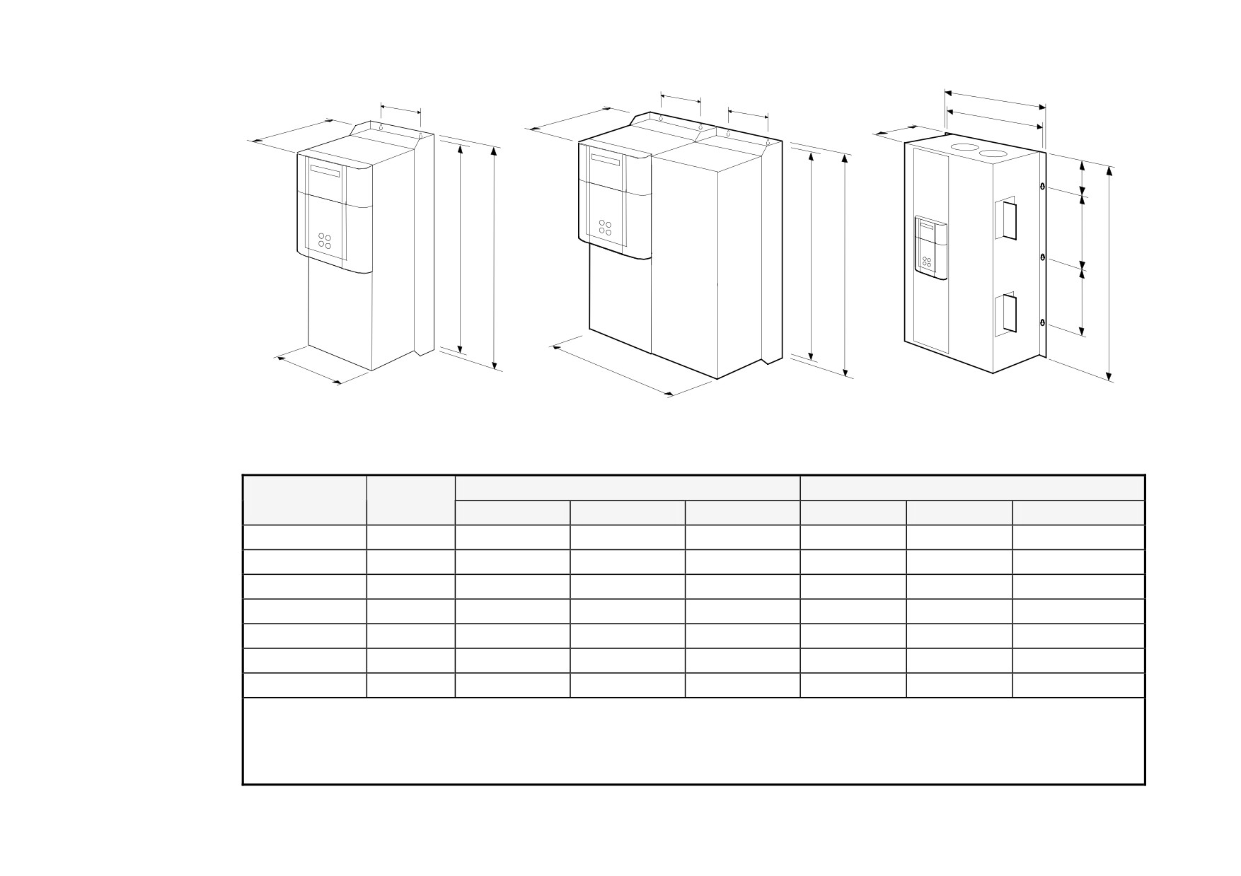
Installing the Drive
3-3
D
A
D
C
D
D
C
C
E1
E2
E1
B
E1
B
B
E2
A
A
380A - 830A
1580A
Frame 4
Frame 5
1200A - 2700A
(vent kit assemblies not shown)
(vent kit assemblies not shown)
Frame H
Current Rating
Weight
Overall Dimensions
Fixing Centres
(A)
Kg (lbs)
A
B
C
D
E1
E2
380
32 (71)
253 (10.0)
700 (27.6)
358 (14.2)
150 (5.9)
680 (26.8)
-
500
32 (71)
253 (10.0)
700 (27.6)
358 (14.2)
150 (5.9)
680 (26.8)
-
725
44 (97)
253 (10.0)
700 (27.6)
358 (14.2)
150 (5.9)
680 (26.8)
-
830
44 (97)
253 (10.0)
700 (27.6)
358 (14.2)
150 (5.9)
680 (26.8)
-
1580
90 (200)
506 (20.0)
700 (27.6)
358 (14.2)
150 (5.9)
680 (26.8)
-
1200 - 2700
See *
850 (33.5)
1406 (55.3)
417 (16.4)
810 (31.9)
78 (3.1)
4 x 400 (15.7)
1200 - 2700
See *
850 (33.5)
956 (37.6)
417 (16.4)
810 (31.9)
78 (3.1)
3 x 400 (15.7)
*590+ drive weighs 270Kg (595.4 lbs) without packaging and fan assembly
591+ drive weighs 160kg (352.8 lbs) without packaging and fan assembly
Fan weighs 18.5Kg (40.8 lbs)
Dimensions are in millimetres (inches)
Refer to “Installation Drawings”, page 3-75.