Parker HPD N (HPD2N, HPD5N, HPD8N, HPD16N, HPD20N,HPD24N). User’s manual (2004) - page 4
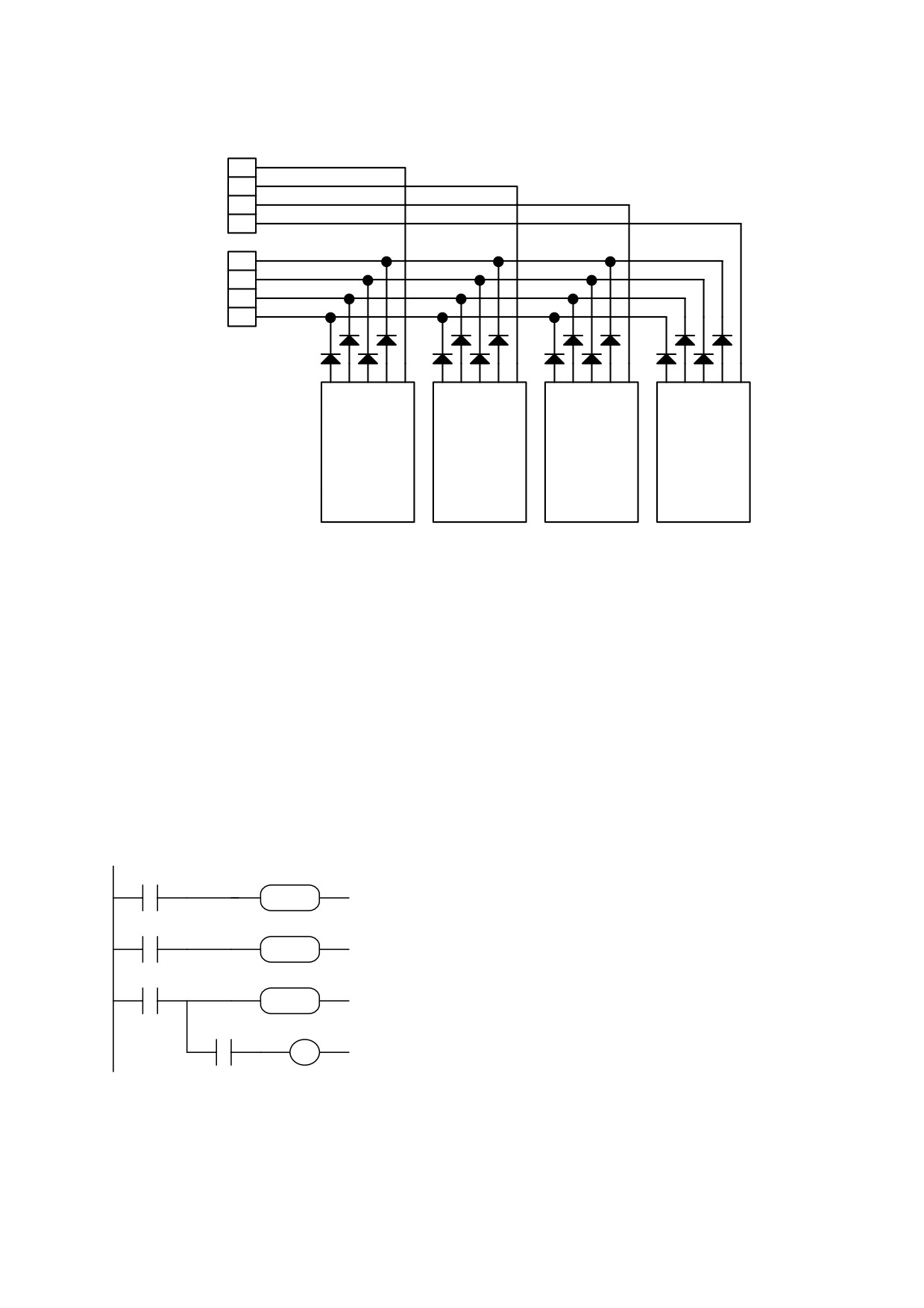
CONNECTION OF 4-DIGIT PRESELECTOR
15
14
X2
13
12
15
14
X3
13
12
1248 C
1248 C
1248 C
1248 C
x1000
x100
x10
x1
Example 14: programmable zero speed window
Assume you want the value of the main analogue reference to remain below a
programmable threshold when it is cancelled. In practice, a speed window around zero rpm is
defined within which speed is set to zero. The value of the threshold is set in parameter Pr88
in rpm; parameter Pr89 is used as an auxiliary memory area.
The required pico-PLC program is as follows:
99.13
07 72 89
LD
99.13
Copy analogue reference value in Pr89
ADD
07.72.89
ADD
89.15
89 71 89
LD
89.15
if Pr89 < 0 invert Pr89 to obtain the
MUL
MUL
89.71.89
modulus
99.13
89 88 72
LD
99.13
calculate difference between Pr89 and
SUB
SUB
89.88.72
Pr88:
99.2
40.6
AND
99.2
OUT
40.6
if negative, set drive to stop
79
4.9. Programming with Pcbrush
The HPD serial kit is supplied to enable communication between a PC and the drive. The
kit includes an RS-422/RS-232 converter, relative 230V~ power supply and serial connection
cable. The enclosed communication software (supplied free of charge) designated Pcbrush
has the following HW/SW requirements: 486 microprocessor or higher, Windows* 3.1 or
more recent version, mouse and serial port for drive connections. The main features of
Pcbrush are:
- serial connection of up to 32 drives
- reading and setting of basic parameters and drive commands
- reading and setting of commands and parameters of operating modes
- functional block diagrams
- pico-PLC program displayed as ladder diagrams
- display of pico-PLC program status during operation
- I/O status
- file storage of parameterisation including pico-PLC program
- uploading of parameterisation including pico-PLC program from a file that can be selected
from among those previously stored
- speed regulator and position controller simulation
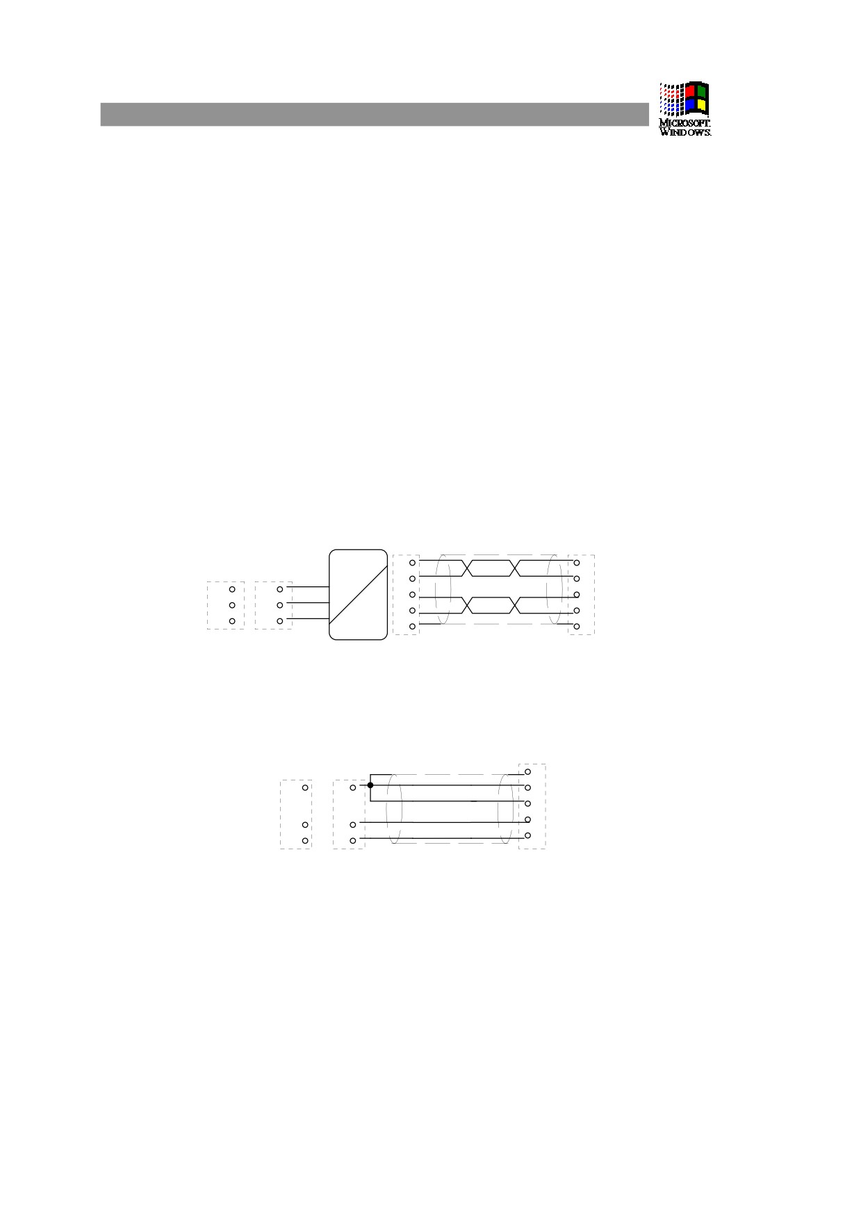
PC - HPD connection layout (HPD serial kit):
CL-422
X5 (HPD)
personal computer
17
1
RS-232
DB9
DB25
tx
5
3
3
2
rx
14
2
2
3
0V
2
4
5
7
RS-422
7
8
refer to text for burden resistors
To create line load (burden) resistances, jumper pins 2 and 6, and pins 4 and 7 on
connector X5 of the last drive on the serial line.
If the PC is a battery powered laptop (i.e. not connected to ground) use the following
connection layout:
personal computer
X5 (HPD)
DB9
DB25
8
5
7
1
2
3
2
3
4
3
2
To install Pcbrush open WINDOWS*, insert the diskette in drive A, select the File menu in
Program Manager and then the Run.option. Now run Setup.exe on [A:\] by typing the
following string on the Command line: A:\setup.exe or by selecting the file with the
Browse...button. The following installation procedure automatically creates a new icon for
Pcbrush. Once the program is installed, launch it by double clicking the relative icon (or select
the icon and then press ENTER).
Set the following parameters on the drive: Pr26=6, Pr27=0, b40.14=1, b42.3=1.
• Windows and the Windows logo are registered trade marks or trade marks owned by Microsoft Corporation in the United States of
America and/or other countries.
80
5. SERIAL INTERFACE
The drive communication protocol is “master-slave” half-duplex type on an asynchronous
RS-485/RS-422 line. The drives assume control of the line only following interrogation by
the master.
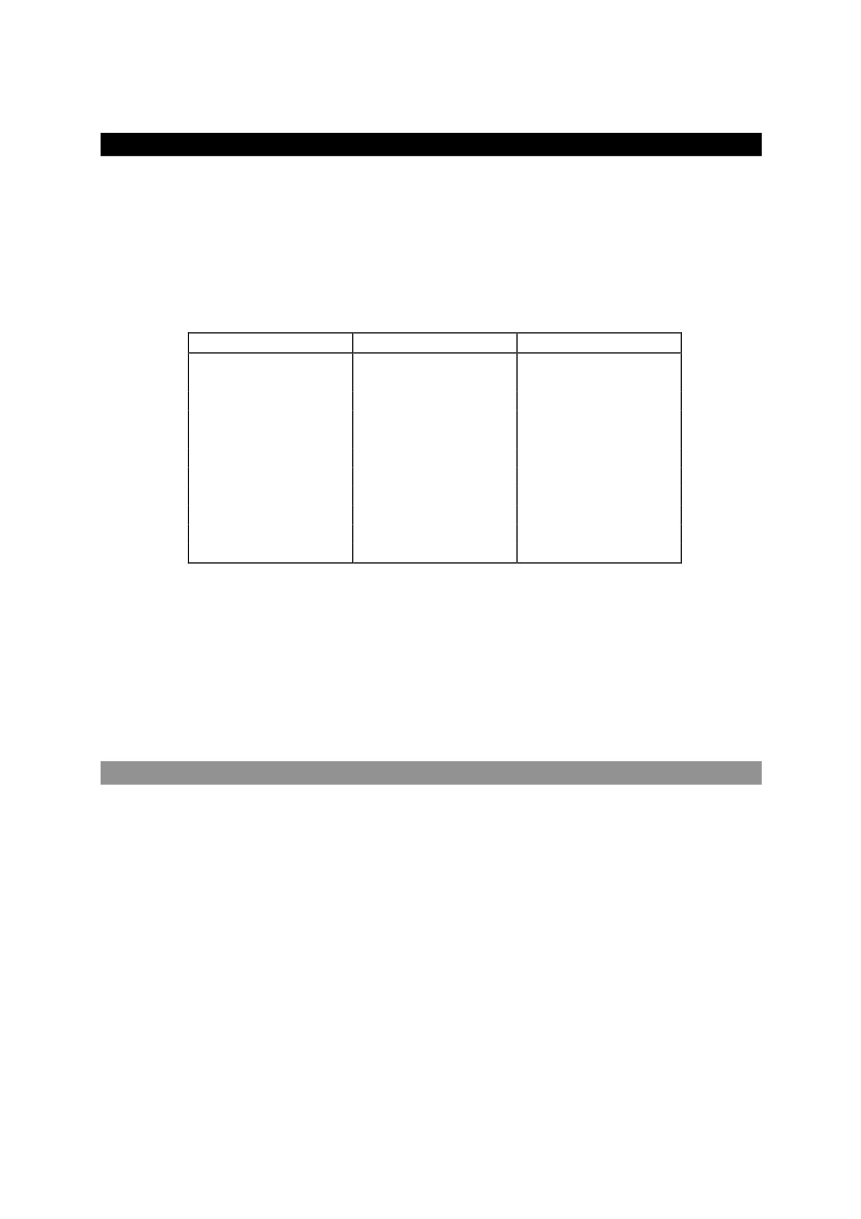
Up to 32 drives can be connected on the same serial line, allocating each a different serial
address in parameter Pr27. It is also possible to set transmission speed in parameter Pr26 as
specified in the table:
Pr26 (decimal base)
b/s
time-out (ms)
0
600
512
1
1200
256
2
2400
128
3
4800
64
4
9600 (*)
32
5
9600
32
6
19200
16
7
38400
12
8
57600
8
9
125000
4
10
57600 (**)
8
(*) The version with code Pr26=4 differs from Pr26=5 because of the 25 ms response delay.
This version was developed to interface with PLCs that require this characteristic.
(**) The version with code Pr26=10 was developed to allow data communication between
two HPD drives.
Refer to the heading Serial line connection for connection diagrams.
5.1. Communication protocol
The right hand column in the table shows the time-out value in milliseconds for each
communication speed; this is the time, starting from the beginning of each message (STX)
within which the transmission of the message must terminate. Therefore, if the message is
interrupted, after the time-out the drive will ignore the information already received and stand
by to receive a new message.
Messages are made up of several consecutive data in the following format:
1 start bit
8 data bits following one byte between square brackets
1 parity bit (even)
1 stop bit
81
The message structure is:
[STX] [CMD+ADDR] [LUN] [PAR] [D0] ... [Dn] [CHK]
where:
[STX] = $7E transmission start indicator. If a field other than STX should assume the value
$7E in the message, this field is followed by a ($00) to ensure that it cannot be interpreted as
an [STX].
[CMD+ADDR] = command and address of peripheral device, always different to zero. This
datum is composed as follows: the first 5 bits (from 0 to 4) define the drive address (from 0 to
31); the remaining 3 bits (from 5 to 7) define the type of message, as described in the
following table:
CMD bit 7 bit 6 bit 5 message type
1
0
0
1
drive response
2
0
1
0
read PLC instruction
3
0
1
1
write PLC instruction
4
1
0
0
read parameter
5
1
0
1
write parameter
6
1
1
0
bit change
7
1
1
1
broadcast parameters to all drives
[LUN] = total number of bytes transmitted (parameter or PLC instruction); can assume values
from 1 to 4. This value must not hold zero characters ($00) after values that coincide with the
initial transmission character ($7E).
[PAR] = parameter or PLC instruction read/write address
[D0] ... [Dn] = datum transmitted.
[CHK] = 256 modulus sum of all fields except [STX] (checksum).
Message types
[CMD1] = drive response to data request, format:
[STX] [001+ADDR] [LUN] [PAR] [D0] ... [Dn] [CHK]
or confirm message in response to data entry or update, format:
[STX] [001+ADDR]
where ADDR identifies the answering drive.
[CMD2] = read message of PLC area instruction; format:
[STX] [010+ADDR] [LUN] [PAR] [CHK]
[CMD3] = write message of PLC area instruction; format:
[STX] [011+ADDR] [LUN] [PAR] [D0] ... [Dn] [CHK]
82
[CMD4] = parameter read message; format:
[STX] [100+ADDR] [LUN] [PAR] [CHK]
[CMD5] = parameter write message; format:
[STX] [101+ADDR] [LUN] [PAR] [D0] ... [Dn] [CHK]
[CMD6] = byte parameter bit change message; format:
[STX] [110+ADDR] [LUN] [PAR] [D0] [D1] [CHK]
In this case (LUN=2) two bytes are transmitted for the data: the first byte is the mask
containing 0 in the positions of the bits to change and 1 in the other positions; the second byte
contains 1 in bit positions to be set to 1 and 0 in the other positions. The address PAR
corresponds to the parameter (byte) in which one or more bits is to be modified. If the
parameter is a word and the bit to be modified is among the first 8 (b0...b7): PAR
=
parameter address; otherwise if the bit to modify is one of the upper 8 (b8...b15): PAR =
parameter address + 1.
[CMD7] = parameter write broadcast message to all drives connected to the serial line;
format:
[STX] [11100000] [LUN] [PAR] [D0] ... [Dn] [CHK]
The address of peripheral device (ADDR) must be zero.
Notes:
- Parameters shown on the display with decimals must be treated as integer values, e.g.
978.5 will be read, and written, as 9785.
- All values preceded by the symbol $ are hexadecimal numbers.
- The value in square brackets is the basic unit (byte) of the message.
- To be considered valid all messages must be terminated within a clearly defined time
interval (time-out) which is a function of speed, and they must have correct parity and
checksum.
- The drive responds to data requests or transmission only if the message is received
correctly; if the message contains an error, no answer will be transmitted. The only
exception is message type 7, with which a datum is transmitted with a single message
addressed to all drives connected to the serial line.
Serial line initialisation and management
Drive serial communication can be enabled or disabled by means of bit b40.14.
The drive is factory set with b40.14=0, i.e. serial line disabled (default).
If you want to use the serial line first set the baud-rate in Pr.26; now set the serial address
in Pr.27; finally, enable serial communication by setting b40.14=1 and initialise using b42.3.
At this point you must save the configuration using command b99.15.
83
For parameter addresses and lengths refer to the relative table.
In the case of PLC instructions, each one occupies 2 or 4 bytes, the format of which is
described below.
Instruction
code
length (bytes)
LD Pa.y
0
2
LDN Pa.y
1
2
OUT Pa.y
2
2
OUTN Pa.y
3
2
AND Pa.y
4
2
ANDN Pa.y
5
2
OR Pa.y
6
2
ORN Pa.y
7
2
ADD Pa, Pb, Pc
8
4
SUB Pa, Pb, Pc
9
4
MUL Pa, Pb, Pc
10
4
DIV Pa, Pb, Pc
11
4
SET Pa.y
12
2
RES Pa.y
13
2
FIN Pb40.y/Pb70.y
14
2
END
15
2
The memory area available for PLC instructions is 128 bytes, with addresses from 0h to 7Fh.
As the minimum length for each instruction is 2 bytes, the PLC program can hold a
maximum of 64 instructions.
The first four bits of the first byte in each instruction (b0..b3) contain the instruction code.
For the first 8 instructions in the table (LD...ORN) and the SET and RES instructions, the
remaining 4 bits of the first byte (b4..b7) contain the value y, while the second byte contains
the value Pa.
For instructions ADD, SUB, MUL and DIV, the second byte contains the value Pa, the
third Pb, and the fourth Pc.
The second byte is not utilised for the END instruction.
For the FIN instruction the fifth bit (b4) of the first byte selects the parameter: b4=0 refers
to Pr.40, b4=1 refers to Pr.70; the sixth bit (b5) of the first byte is used for negative logic if
required: b5=0 the bit is copied; b5=1 the bit is inverted and then copied. The second byte of
the FIN instruction contains the value of y.
If FIN instructions are used they must be the first of the program and there must be no
more than 3 so they will occupy addresses from 0h to 5h. If a FIN instruction is included from
address 6h forward or, anyway, after any other instruction, it will be ignored (NOP).
The instructions must be one after the other starting from address 0h, without any free bytes.
There is just one program and it terminates with the END instruction.
84
Serial line application examples
For a better understanding of how to implement the serial line communication protocol, we
have provided a few examples for each type of message.
The values are entered simply by way of example.
Case 1: reading a 1 byte parameter
Assume you want to read the value of parameter Pr.31 (operating mode), and that the value of
this parameter is 9; assume the drive serial address is 0. The message to transmit is:
[$7E][$80][$01][$54][$D5]
The drive answers with the message:
[$7E][$20][$01][$54][$09][$7E][$00]
Case 2: reading a 2 byte parameter
Assume you wish to read the reference speed (Pr.7) and that the relative value is 2000;
assume also that the drive serial address is 1. The message to transmit is:
[$7E][$81][$02][$42][$C5]
The drive answers with:
[$7E][$21][$02][$42][$D0][$07][$3C]
Case 3: writing a 1 byte parameter
Assume you want to select operating mode 1 (Pr.31); assume also that the drive serial address
is 3. The message to transmit is:
[$7E][$A3][$01][$54][$01][$F9]
The drive answers with:
[$7E][$23]
Case 4: writing a 2 byte parameter
Assume you intend to set rated current at 25.3% (Pr.33); assume also that the drive serial
address is 3. The message to transmit is:
[$7E][$A3][$02][$C6][$FD][$00][$68]
The drive answers with:
[$7E][$23]
Case 5: setting a bit to 1
Assume you want to enter the command to save the PLC program (b99.14=1); assume also
that the drive serial address is 0. The message to transmit is:
[$7E][$C0][$02][$93][$BF][$40][$54]
The drive answers with:
[$7E][$20]
85
Case 6: setting a bit to 0
Assume you want to disable the drive by software (b40.9=0); assume that drive serial address
is 0. The message to transmit is:
[$7E][$C0][$02][$5D][$FD][$00][$1C]
The drive answers with:
[$7E][$20]
Case 7: writing a PLC instruction
Assume you want to set the first PLC instruction as: LD 90.4; assume the drive serial address
is 0. The message to transmit is:
[$7E][$60][$02][$00][$40][$5A][$FC]
The drive answers with:
[$7E][$20]
Case 8: reading the first PLC instructions
Assume you want to read the first instructions of the PLC default program; assume the serial
address of the drive is 0. The message to transmit is:
[$7E][$40][$04][$00][$44]
The drive answers with the message:
[$7E][$20][$04][$00][$10][$5A][$A7][$5A][$8F]
which corresponds to the acquisition of the following instructions: LD 90.1, ORN 90.10.
86
5.2. Serial addresses and parameter lengths
Parameter
Address
Length Meaning
Pr0
038h
2
motor speed in rpm
Pr1
034h
2
analogue reference
Pr2
03Ah
2
full scale 1
Pr3
03Ch
2
full scale 2
Pr4
036h
2
frequency full scale
Pr5
03Eh
2
internal reference
Pr6
040h
2
reserved reference
Pr7
042h
2
chosen reference
Pr8
0AEh
2
positive acceleration in seconds
Pr9
0B0h
2
positive deceleration in seconds
Pr10
0B2h
2
negative acceleration in seconds
Pr11
0B4h
2
negative deceleration in seconds
Pr12
0B6h
2
limit switch deceleration
Pr13
0B8h
2
overspeed threshold
Pr14
044h
2
top speed limit
Pr15
046h
2
lower speed limit
Pr16
048h
2
integral gain
Pr17
0BAh
2
damping factor
Pr18
0BCh
2
filter time constant
Pr19
0BEh
2
user current limit
Pr20
04Ah
2
DC bus voltage
Pr21
04Ch
2
reserved torque limit
Pr22
04Eh
2
auxiliary reference
Pr23
051h
1
current alarm code
Pr24
052h
1
previous alarm code
Pr25
053h
1
software version code
Pr26
05Eh
1
baud rate
Pr27
05Fh
1
serial address
Pr28
0C0h
2
shaft position (0..4095)
Pr29
061h
1
motor poles
Pr30
0C2h
2
resolver offset
Pr31
054h
1
operating mode
Pr32
0C4h
2
rated motor speed
Pr33
0C6h
2
rated current
Pr34
055h
1
scale factor for tacho generator
Pr35
0C8h
2
filtered torque request
Pr36
058h
2
i2t accumulation
Pr37
05Ah
2
thermal image for braking
Pr38
0CAh
2
auxiliary analogue output
Pr39
0CCh
2
K for phase advance
Pb40
05Ch
2
flags used by main block
87
Pb41
056h
2
flags used by main block
Pb42
060h
1
flags used by main block
Pr50
064h
2
Pr51
066h
2
Pr52
068h
2
Pr53
06Ah
2
Pr54
06Ch
2
Pr55
06Eh
2
Pr56
070h
2
Pr57
072h
2
Pr58
074h
2
Pr59
076h
2
Pr60
078h
2
Pr61
07Ah
2
Pr62
07Ch
2
Pr63
07Eh
2
Pr64
080h
2
Pr65
082h
2
Pr66
084h
2
Pr67
086h
2
Pr68
088h
2
Pr69
08Ah
2
Pb70
062h
2
flags used by operating mode
Pr80
0CEh
2
Pr81
0D0h
2
Pr82
0D2h
2
Pr83
0D4h
2
Pr84
0D6h
2
Pr85
0D8h
2
Pr86
0DAh
2
Pr87
0DCh
2
Pr88
0DEh
2
Pr89
0E0h
2
Pb90
0E2h
2
inputs
Pb91
08Ch
2
outputs
Pr92
08Eh
2
timer 1
Pr93
090h
2
timer 2
Pb94
032h
1
flags used by PLC
Pb99
092h
2
flags used for PLC and commands
PLC area length: 128 bytes, addresses 00h to 7Fh.
88
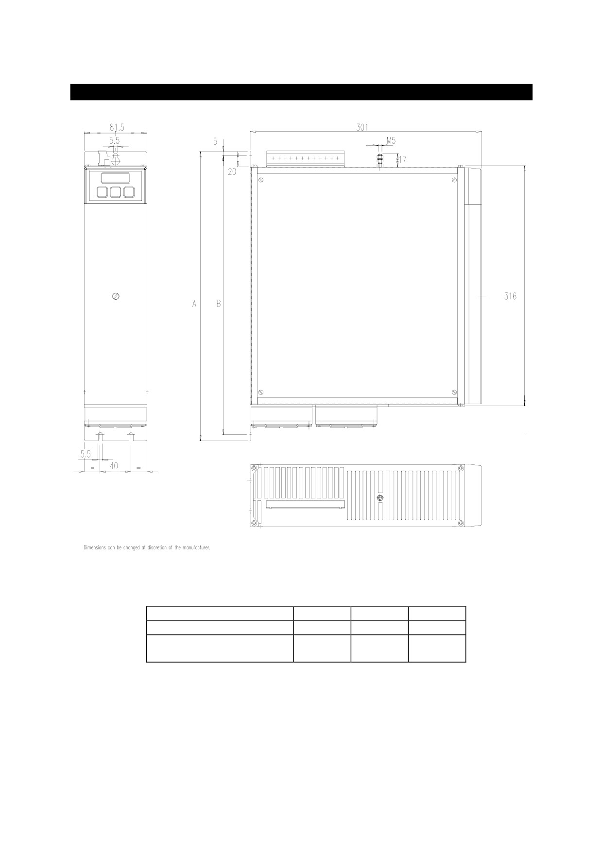
6. Appendix A: HPD drive mechanical dimensions
drive type
A
B
weight kg
HPD2N
348
335
5.1
HPD5N, HPD8N, HPD16N,
377
364
5.5
HPD20N,HPD24N
89
7. Appendix B: hardware characteristics
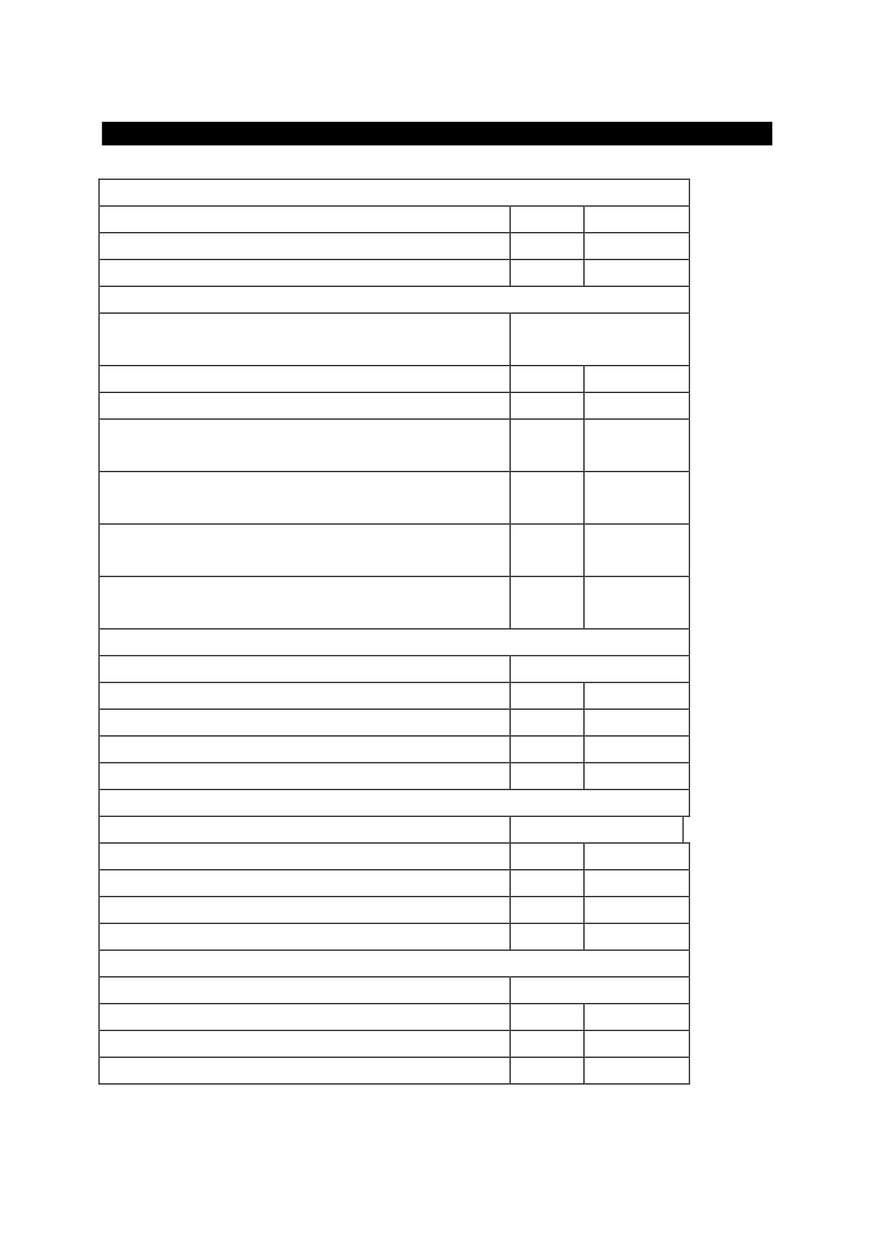
digital input
input impedance
7k
ohm
VH
15..30
V
VL
0..3
V
digital output
type
PNP open
collector
VH using internal supply
20..26
V
IO for single output
100
mA
IT current for all outputs using internal
200
mA
supply
IT current for all outputs using ext. supply
500
mA
+24 VIN
VSW max. voltage between out 6 A and
110
V~
out 6 B
ISW max. current trough out 6 A and out
600
mA
6 B
analogue reference
type
differential
impedance
20
Kohm
range
± 10
V
CMMR
> 60
dB
resolution
15
bits
aux. analogue input
type
differential
impedance
250
Kohm
range
± 10
V
CMMR
> 40
dB
resolution
10
bits
analogue output
type
single ended
IO max.
1.5
mA
range
± 10
V
resolution
8
bits
90
8. Appendix C: DC bus voltage thresholds
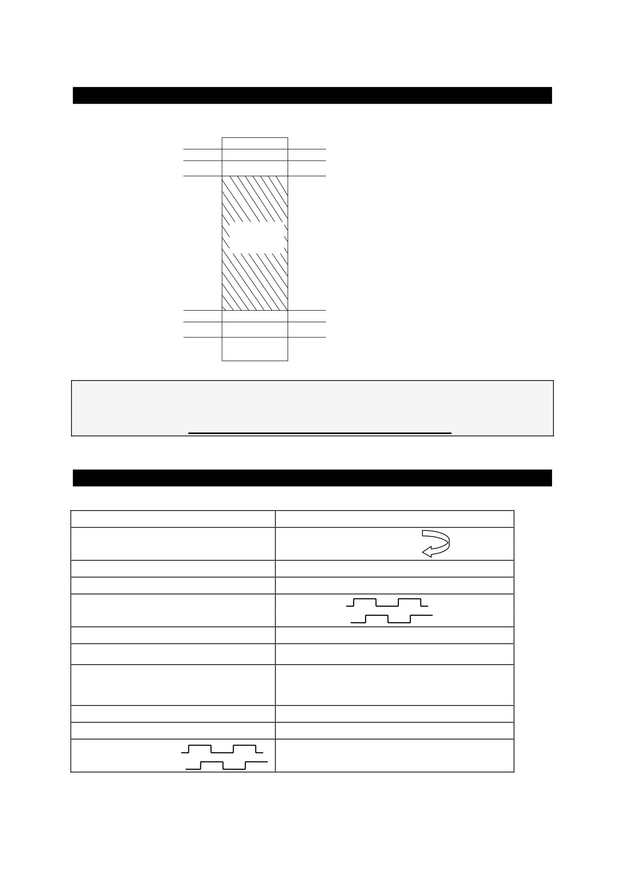
1024
870
OVER VOLTAGE
805
Brake - high treshold
780
Brake - low treshold
normal
operation
area
120
in-rush control excluded
56
UNDER VOLTAGE
40
in-rush control included
0
The modification of the above thresholds makes
potentially dangerous to wire together the DC BUSes of
HPD”N” drives with HPD drives.
9. Appendix D: Standard settings
Reference
Positive
Shaft moving
(motor shaft view):
Torque monitor
Positive
R/D Counter
UP
Encoder out
A
B
tacho signal
positive
Iu
torque • sin(ϑ)
Iv
⎛
2•π⎞
torque • sin⎜ϑ
+
⎟
⎝
3
⎠
IN AUX positive
Pr22 positive
Pr38 positive
OUT AUX. Positive
Encoder In. A
Counter Up
B
91
10. Appendix E: Software timers
Time slot
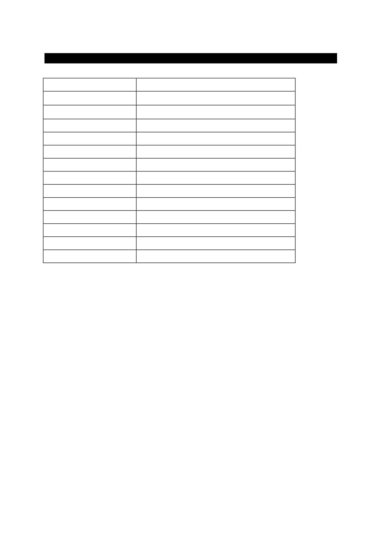
Task running
256 µs
Torque vector generation
512 µs
Speed loop
Fast operating mode manager
Torque limit evaluation
Speed reference manager
Brake resistor manager
Fast input
2.048 ms
Slow operating mode
6.144 ms
Motor thermal image algorithm
Digital input
PLC instruction scan
Digital output
49.152 ms
Speed windows manager
92
11. Appendix F: pico-PLC default program
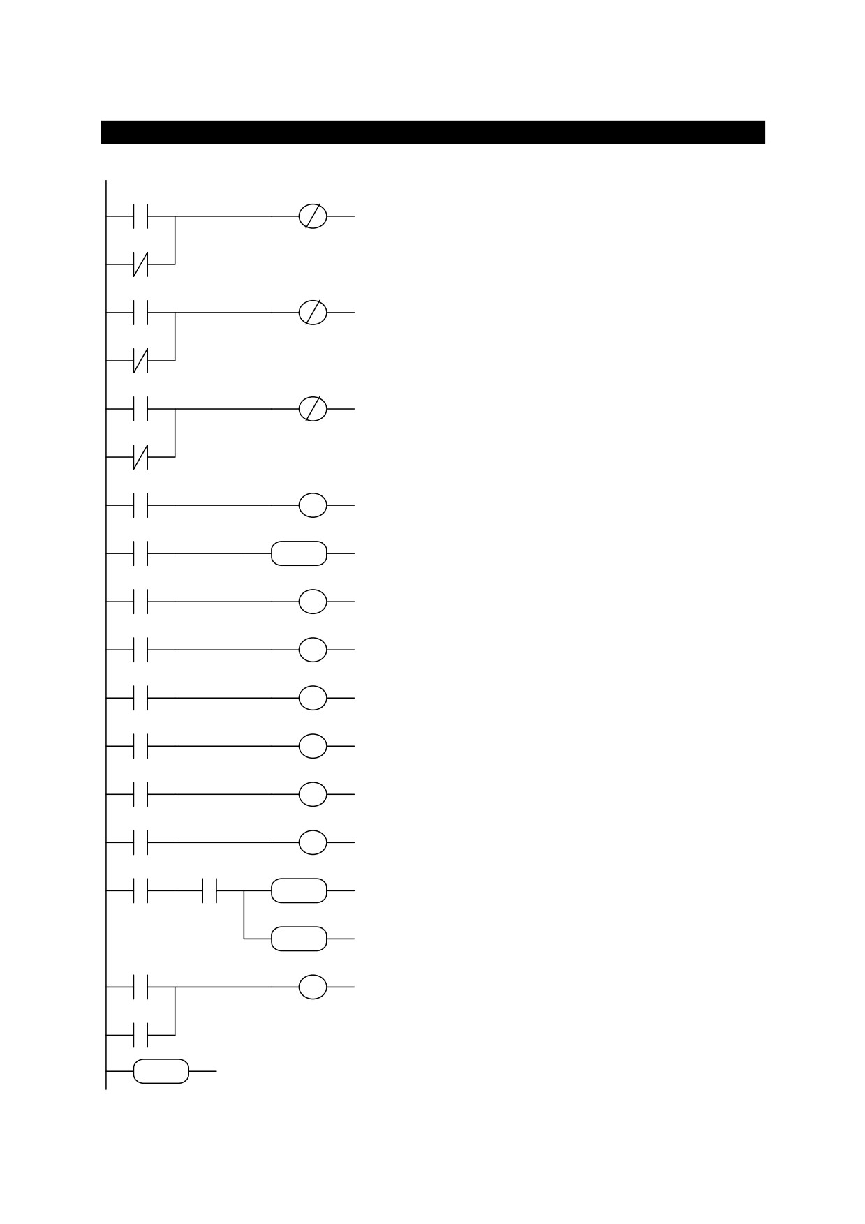
90.1
40.4
LD
90.1
digital input 1 for left hand limit
ORN
90.10
switch enabled only if b90.10=1
OUTN
40.4
90.10
90.2
40.5
LD
90.2
digital input 2 for right hand limit
ORN
90.10
switch enabled only if b90.10=1
OUTN
40.5
90.10
LD
90.3
90.3
40.6
digital input 3 for emergency stop
ORN
90.10
enabled only if b90.10=1
OUTN
40.6
90.10
LD
90.4
digital input
4 for clockwise or
90.4
40.0
OUT
40.0
counter-clockwise rotation
LD
90.5
digital input 5 for start/stop reset
90.5
05 05 05
SUB
05,05,05
parameter Pr5
SUB
LD
41.0
41.0
91.0
digital output
0 indicates speed
OUT
91.0
greater than Pr13
LD
41.1
digital output
1 indicates motor
OUT
91.1
41.1
91.1
speed = reference
digital output
2 indicates motor
LD
41.2
speed = 0
41.2
91.2
OUT
91.2
digital
output
3
indicates
LD
41.3
clockwise or counter-clockwise
OUT
91.3
motor shaft rotation
41.3
91.3
LD
41.4
digital output
6 indicates drive
OUT
91.6
41.4
91.6
healthy
LD
41.11
digital output
4 indicates active
OUT
91.4
motor thermal image
41.11
91.4
LD
90.11
if b90.11=1 the drive performs a
AND
99.0
direction inversion at
6 second
90.11
99.0
92 78 92
ADD
92,78,92
intervals at the speed in Pr5
MUL
05,71,05
ADD
05 71 05
LD
90.5
MUL
digital input
5 for start/stop
OR
90.11
90.5
40.12
disabled if b90.11=1
OUT
40.12
END
90.11
program end
END
93
12. Appendix G: flash information
• USE b99.15 TO SAVE PARAMETERS
• USE b99.14 TO SAVE PLC PROGRAM
• TO CHANGE PLC INSTRUCTIONS b99.13 MUST BE AT 0
• WHEN CHANGING OPERATING MODE USE b99.11 TO LOAD DEFAULT
PARAMETERS (b40.2=0)
• WARNING, BEFORE CHANGING Pr31 MAKE SURE b40.2=0
• SPEED REFERENCE IS LIMITED TO THE VALUE IN Pr32
• IN TORQUE CONTROL Pr2 AND Pr3 MUST BE SET TO 1000
• TO USE THE ACTIVE OPERATING MODE b40.2 MUST BE SET TO 1
• TO USE Pr32 TO CHANGE FEEDBACK RESOLUTION ON THE FLY, DISABLE
TORQUE COMPENSATION (b42.6=0)
• IF YOU CANNOT UPDATE READ/WRITE PARAMETERS FROM THE KEYPAD,
MAKE SURE b99.7=0. IF b99.7=0, THE PARAMETERS ARE PROBABLY
MANAGED BY THE PLC PROGRAM.
94
13. Appendix H: Alarms
If problems are encountered with the drive or the control system, use the following table to
identify the fault and take the recommended corrective action.
To cancel the error on the drive, first remedy the cause and then set Pb99.10 = 1 (reset).
Error Code HPD: 1
Over Voltage on the D.C. Link. Check the three-phase power
line (max 460 V).
Check the break circuit and the braking resistor
Error Code HPD: 2
Under Voltage on the D.C. Link. Check the three-phase power
line (minimum voltage: 90 V).
Over current. Check for any mechanical blockage and make
Error Code HPD: 3
sure the motor is the appropriate size for its current use.
Check the motor connections and for any phase-phase or phase-
ground short-circuits.
Check the machine speed and the service cycle.
Make sure a line trap isn’t connected to the motor!
Resolver. Check the connections of the resolver and the
Error Code HPD: 4
connectors on both sides (drive-motor).
Error Code HPD: 5
Motor Over Temperature
Check the connection of the PTC motor on terminals 1 and 2 of
X1.
Check the settings of parameters Pr33
(Inom) and Pr19
(Ipicco).
Error Code HPD: 6
Drive Over Temperature. Check the cooling fans and for any
restrictions to air flow.
Check the breaking cycle.
Check the environmental temperature of the electrical control
panel where the drive is installed, as well as the external
room temperature.
Check the external fuses on the three-phase power supply.
On start up, the display
Make sure that the line traps
(if installed) and motor are
doesn’t read IDLE or
connected correctly.
RUN or it stays off
Check the voltage on the power supply terminals X4, terminals
1, 2, and 3.
Check the bridge on X4 between terminals 7 and 8.
95
Check the keypad connection and make sure it was installed
correctly.
The HPD’s LED display
The drive goes in I2T mode due to an overload (it required
shows decimal points on
more current that was available).
all characters
Check:
-
The cables between motor and HPD (there should be
no inverted phases). Take special care with motors with
terminals rather than the connector: it’s easy to make a
mistake. Adhere strictly to the wiring diagrams.
Mechanical measurements
Motor runaway occurs
The most likely cause of this is an incorrect connection
when the drive is
between the encoder output of the drive
(X7) and the
enabled.
encoder input on the axis control.
Another possibility is an incorrect connection between the
terminals of the analogue output of the axes (DRV1 and Gnd)
and the analogue reference input of the HPD (X2-terminals 1
and 2 with shielding on terminal 3).
Check the wiring of both the analogue reference signal
cable and the reaction signal cable (encoder). If correct,
invert the analogue input on the HPD (X2, terminals 1 and
2).
See below if the motor now rotates in the wrong direction.
The motor turns slowly
The drive isn’t under the control of the axis controller.
when the drive is
Check the cable connecting the encoder output (X7) and the
enabled.
axis controller.
Check the analogue reference cable connecting the drive (X2 -
terminals 1, 2, and 3) and the axis controller.
Make sure the analogue output of the axis controller is putting
out a current.
The motor doesn’t move
Make sure the display shows RUN when the drive is enabled.
and has no torque.
If not, check the connection between X3-terminals 11 and
19. Recheck the programming of the HPD and the wiring.
Check the I/O signals for the axis controller.
The motor turns in the
Invert the encoder signals A & /A and the analogue reference
wrong direction
inputs on the HPD (X2 - terminals 1 and 2).
96
14. Appendix I:options
For the HPD converters, the following options are also available:
Operator Interfaces
Field bus interfaces
profibus-dp
EC-4
Device Net
EC-4
CanBus
EC-4
ModBus
EC-4
Sercos
EC-4
Absolut encoder interfaces
SSI
EC-4
Hiperface
EC-4
I/O expansions
EC-4 - I/O BOX
High performance axis controls
EC-4
Preparation for the expansion boards.
If you wish to use expansion boards such as the EC-4 or the EC-5, the converter must be ordered with
the code HPD x NE0, where x is the nominal current.
97
15. Appendix L: EC4
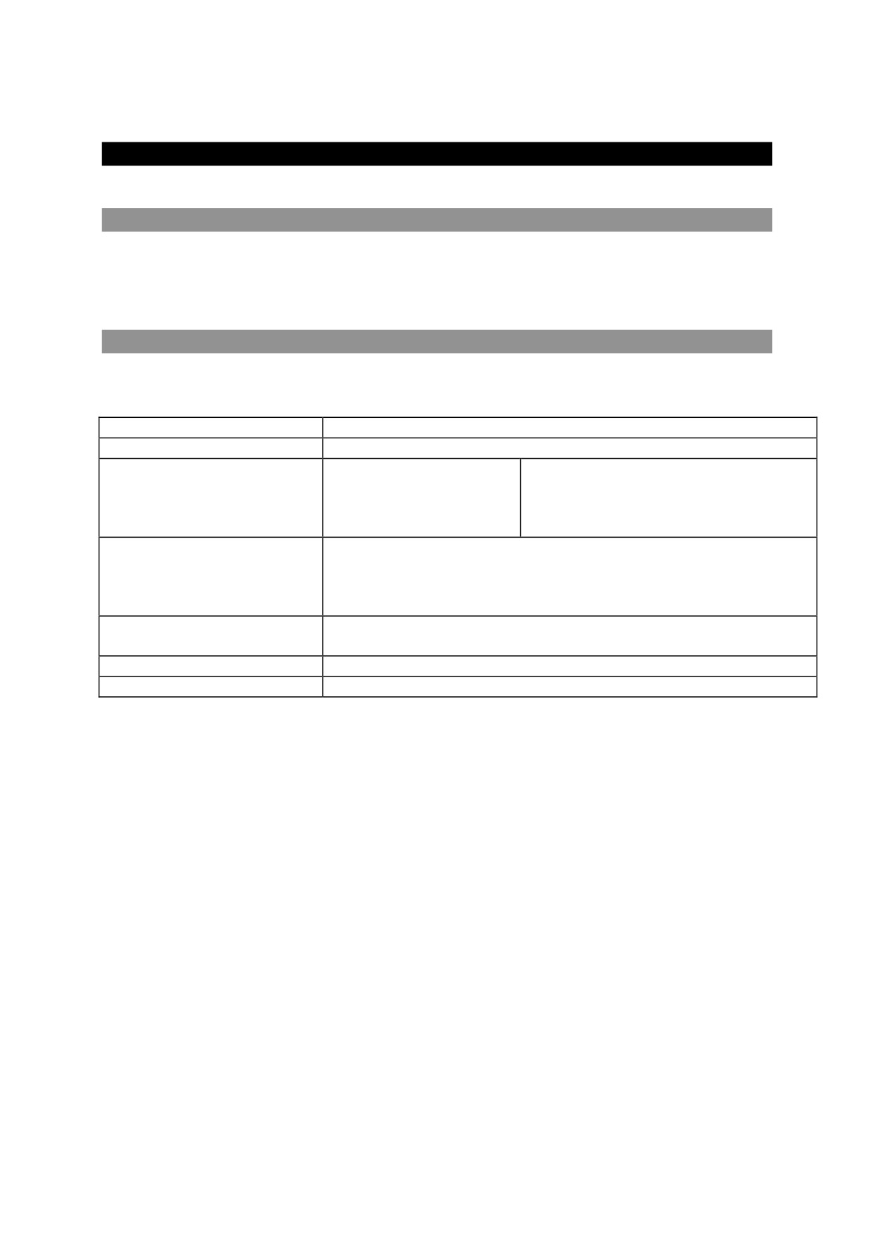
15.1. Product description
EC-4 is an expansion board for HPD-series converters which significantly improves performance.
Basically, the code EC-4 identifies a hardware product. To use the EC-4, you need to install the
software required.
15.2. Main characteristics
The main characteristics of the EC-4 are shown in the table below:
Format
Europe 1 measurements 100 x 160 mm
Degree of protection
IP 00
Field bus
Profibus-DP
Up to 12 Mb
CAN bus
DeviceNet
SBCCan
RS-422
ModBus for operator panel
Feedback used for the
Resolver (directly via HPD)
position loop
Incremental encoder 5 V RS - 422
SSI absolute encoder
Hyperface absolute encoder
Power supply for auxiliary
programmable voltage 5V - 8V - 12V - 15V
encoders
250mA protected.
Digital inputs
8 PNP-type
Digital outputs
8 PNP-type 100mA with short-circuit protection
ATTENTION !
EC-4 is only for drive
HPD x N EO
EC-4 can only be installed on drives with a certain software version or higher
98
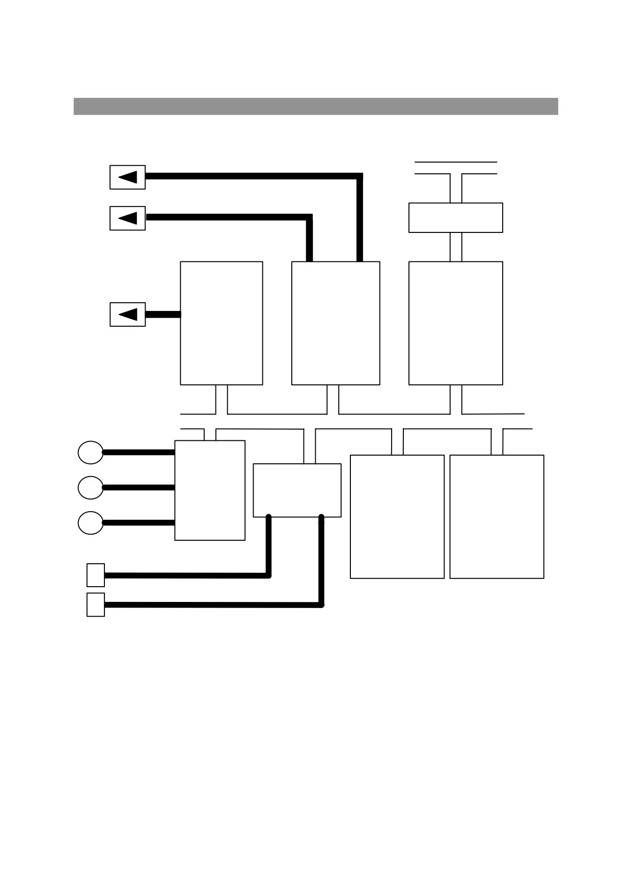
15.3. EC-4 block diagram
HPD bus
ModBus link
Can driver
hpd bus-interface
rs-485 driver
LSPM-2
idt 7233
C167
profibus-dp
can
2K x 16 dp ram
SSI
E
Hiperface
encoders
I/O
E
interface
controller
AM 29F100
2 x TC 551001
incremental
E
64K x 16 flash
128K x 16 ram
8 input
8 output
99
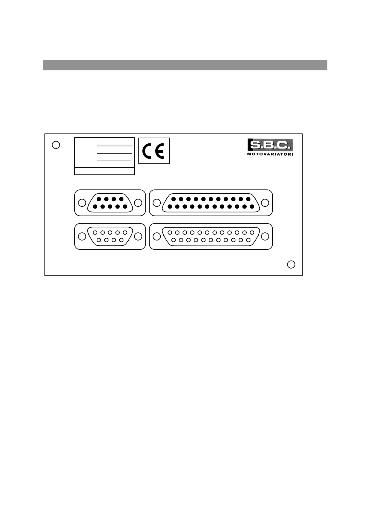
15.4. Product and connectors identification
The SW field on the label of the EC-4 panel must be filled in using indelible ink by the person
who installed the software
P/N
EC4 Exx
S/N
xxxxxxxx
SW
EC-4
CAN
DIGITAL I / O
PROFIBUS-DP
ENCODER - SERIAL LINK
100
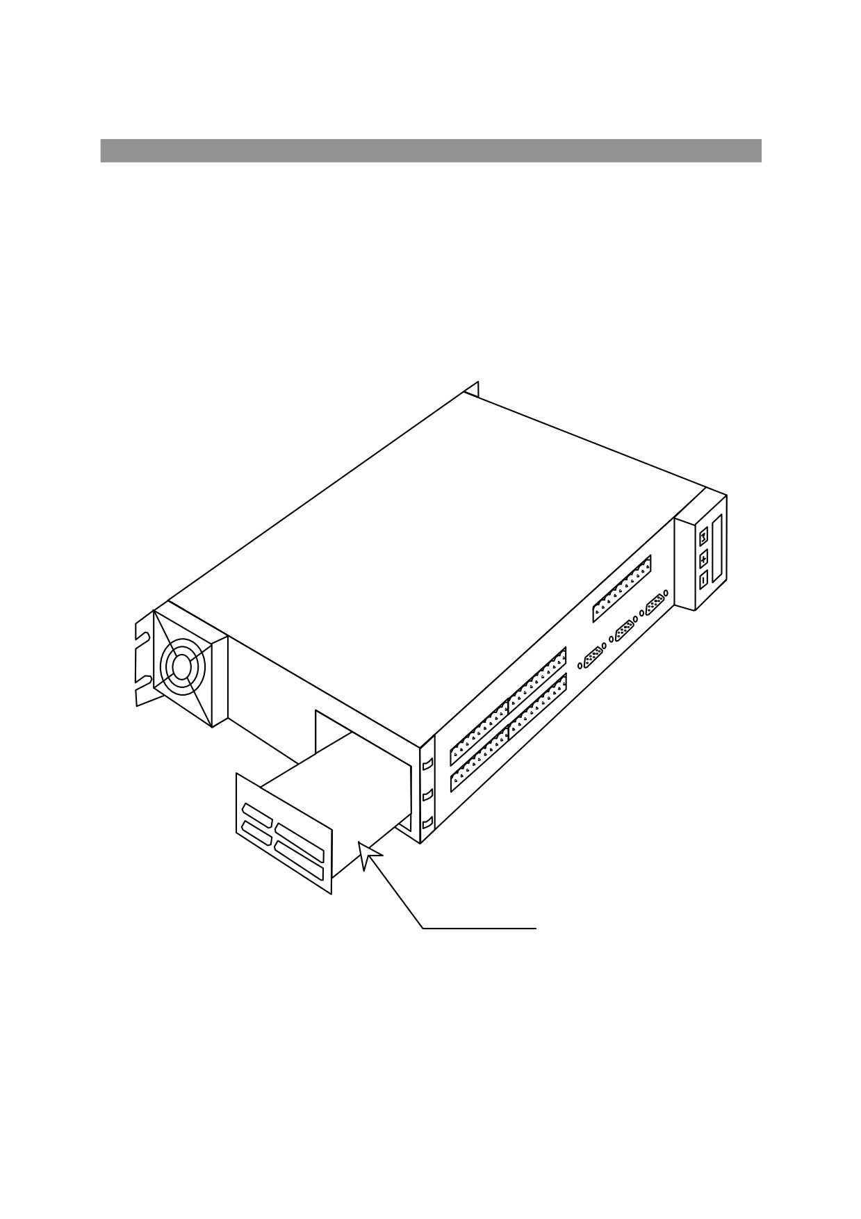
15.5. EC-4 installation
ATTENTION
HIGH VOLTAGE
Before installing the EC-4 board, make surue that no wires are connected to the HPD converter.
Remove the lower panel
Insert the EC-4 board
Screw the EC-4 panel in to the body of the HPD
EC-4
101
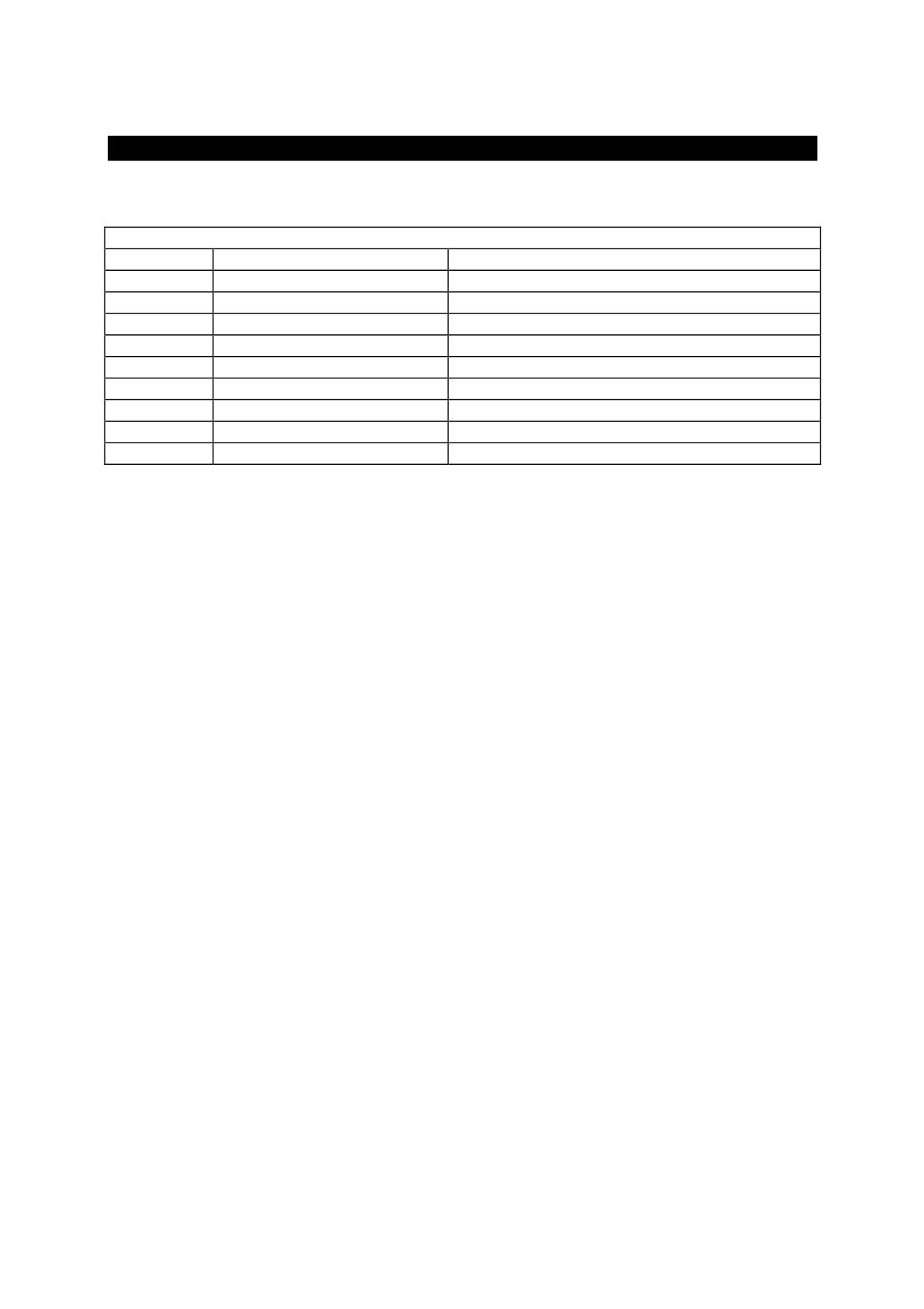
16. Profibus-DP connector
The Profibus-DP connector is a 9-pin female connector.
PROFIBUS-DP CONNECTOR
N. Pin
Signal
Description
1
n.c.
2
n.c.
3
RxD / TxD - P
Line of communication +
4
CNTR - P
Controll signal for ripetitor
5
DGND
Ground
6
VP
Terminal supply
7
n.c.
8
RxD / TxD - N
Line of communication -
9
n.c.
The Profibus-DP interface is optional, and must therefore be expressly requested when ordering the
EC-4 board.
The Profibus interface implemented is based on the ASIC LSPM2. The EC-4 is seen by the profibus
master as a remote I/O module with 16 inputs and 16 outputs. Obviously, the I/Os are virtual.
Interpretation of the meaning of the I/Os will be defined by the program installed on the EC-4
board.
The configuration file SBC0EC4.GSD is provided to configure the EC-4 as a slave Profibus-DP.
102
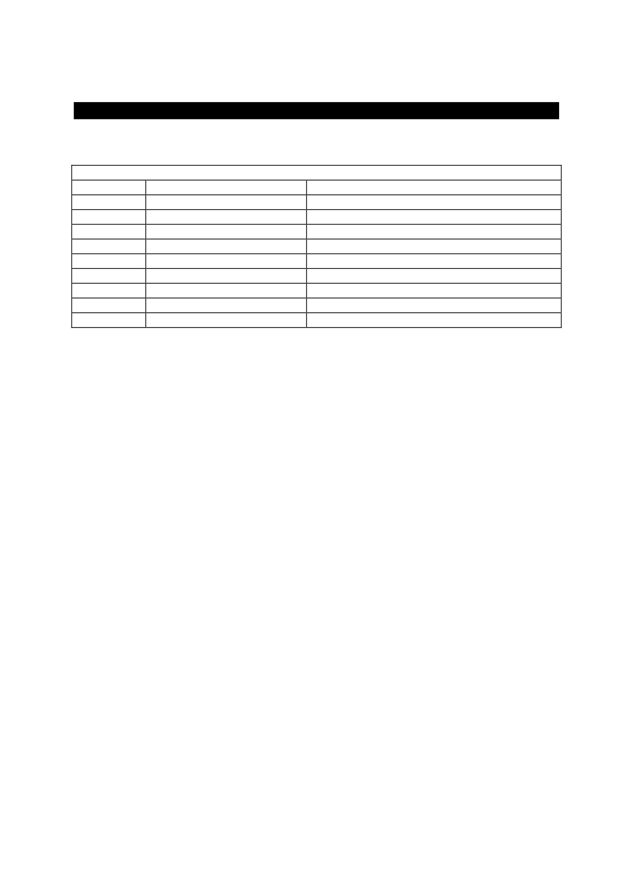
17. Can Bus Connector
The Can bus connector is a 9-pin male connector.
CAN BUS CONNECTOR
N. Pin
Signal
Description
1
n.c.
2
CAN_L
Line of communication low
3
CAN_GND
Ground
4
n.c.
5
CAN_SHLD
Shield
6
GND
Ground
7
CAN_H
Line of communication high
8
n.c.
9
n.c.
Two application layers are available for the Can interface.
The first is SBCCAN, which enables master/slave communication, as well as slave/slave
communication. It includes synchronism telegrams, transmissions to slave groups, and cyclic,
acyclic, and interrupt transmissions. There is also a subset of SBCCAN which allows for simple
data exchange between SBC drives (IDC inter-drive communication).
The second is DeviceNet. With the DeviceNet interface implemented, the EC-4 is seen by the master
as a remote I/O module with 256 inputs and 256 outputs. Obviously, the I/Os are virtual.
Interpretation of the meaning of the I/Os will be defined by the program installed on the EC-4
board.
103
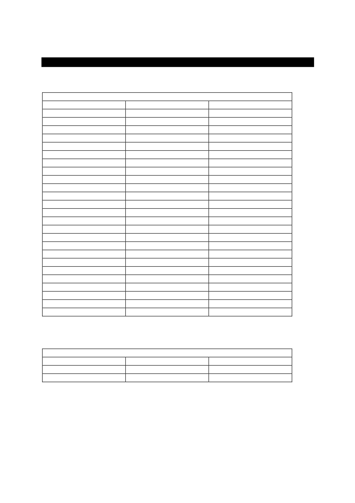
18. Digital I/O
The Digital I/O connector is a 25-pin male connector
DIGITAL I/O CONNECTOR
N. Pin
Signal
Description
1
DIN-0
DIGITAL INPUT 0
2
DIN-1
DIGITAL INPUT 1
3
DIN-2
DIGITAL INPUT 2
4
DIN-3
DIGITAL INPUT 3
5
DIN-4
DIGITAL INPUT 4
6
DIN-5
DIGITAL INPUT 5
7
DIN-6
DIGITAL INPUT 6
8
DIN-7
DIGITAL INPUT 7
9
+24Vin
COMMON OUT
10
+24Vin
COMMON OUT
11
+24Vin
COMMON OUT
12
+24Vin
COMMON OUT
13
+24Vin
COMMON OUT
14
DOUT-0
DIGITAL OUTPUT 0
15
DOUT-1
DIGITAL OUTPUT 1
16
DOUT-2
DIGITAL OUTPUT 2
17
DOUT-3
DIGITAL OUTPUT 3
18
DOUT-4
DIGITAL OUTPUT 4
19
DOUT-5
DIGITAL OUTPUT 5
20
DOUT-6
DIGITAL OUTPUT 6
21
DOUT-7
DIGITAL OUTPUT 7
22
0V
COMMON IN
23
0V
COMMON IN
24
0V
COMMON IN
25
0V
COMMON IN
It uses digital PNP-type inputs. The characteristics common to all inputs are as follows:
DIGITAL INPUTS
Impedence input
6K
Ohm
VH
15...30
V
VL
0...3
V
104