Parker HPD N (HPD2N, HPD5N, HPD8N, HPD16N, HPD20N,HPD24N). User’s manual (2004) - page 5
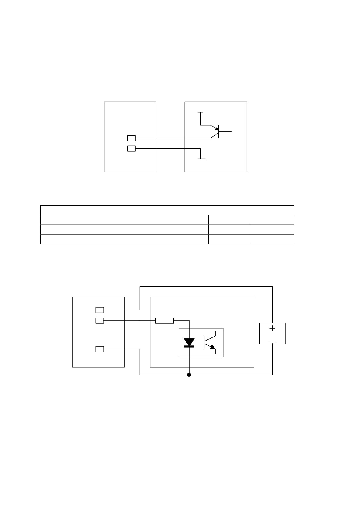
The output that guides an input of the EC-4 board must be a PNP type and have the 0V signal
connected to one of the pins from 22 to 25.
example: EC-4 digital input connection
24V
pin 1
pin22
0V
EC-4
PLC
The outputs are PNP-type. The common of the outputs of pins 9..13 must be connected to an
external 24V power supply. The characteristics of the outputs are:
digital outputs
type
PNP open collector
I/O for a single output
100
mA
Maximum total current
500
mA
example: EC-4 digital output connection
pin 9
pin 14
+24 V
pin 22
EC-4
PLC
N.B.
All inputs can be configured to capture values
All outputs can be configured to provide value comparison
outputs
105
19. Encoder and serial link
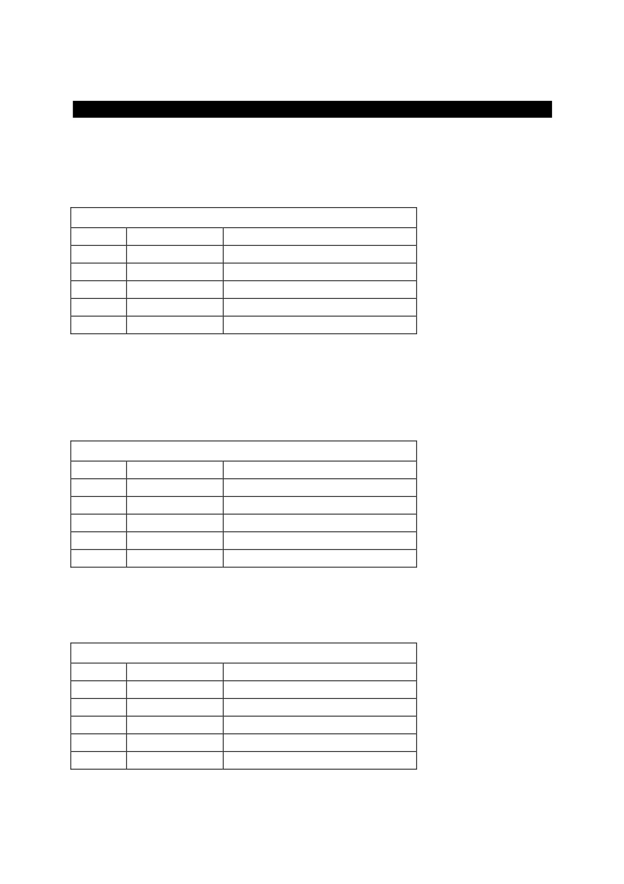
The encoder connector and serial link is a 25-pin female connector.
The pins of the encoder connector and serial link change meaning as a function of the
connection and the drive software installed. The following tables present the typical
configurations.
DEBUG MODE CONNECTION
N. Pin
Signal
Description
1
TX+
line TX RS-422 positive
2
TX-
line TX RS-422 negative
3
RX+
line RX RS-422 positive
4
RX-
line RX RS-422 negative
6
GND
0V
With the “DEBUG MODE” connection and using an RS-422/RS-232 converter, you can
connect the EC-4 board to a personal computer and, using the software installed on the PC,
test the user program.
Using the same communication port, you can also load software already installed in the flash
memory of the EC-4 board.
ModBus CONNECTION
N. Pin
Signal
Description
1
TX+
line TX RS-422 positive
2
TX-
line TX RS-422 negative
3
RX+
line RX RS-422 positive
4
RX-
line RX RS-422 negative
6
GND
0V
The ModBus connection makes it possible to connect a ModBus-configured operator panel to
the EC-4 board. To manage the ModBus, you need to load the drive software that will
provide access to the entire parameter area for the operator panel.
IncrementalEncoder CONNECTION
N. Pin
Signal
Description
14
A+
Phase A positive
15
A-
Phase A negative
16
B+
Phase B positive
17
B-
Phase B negative
21
GND
0V
106
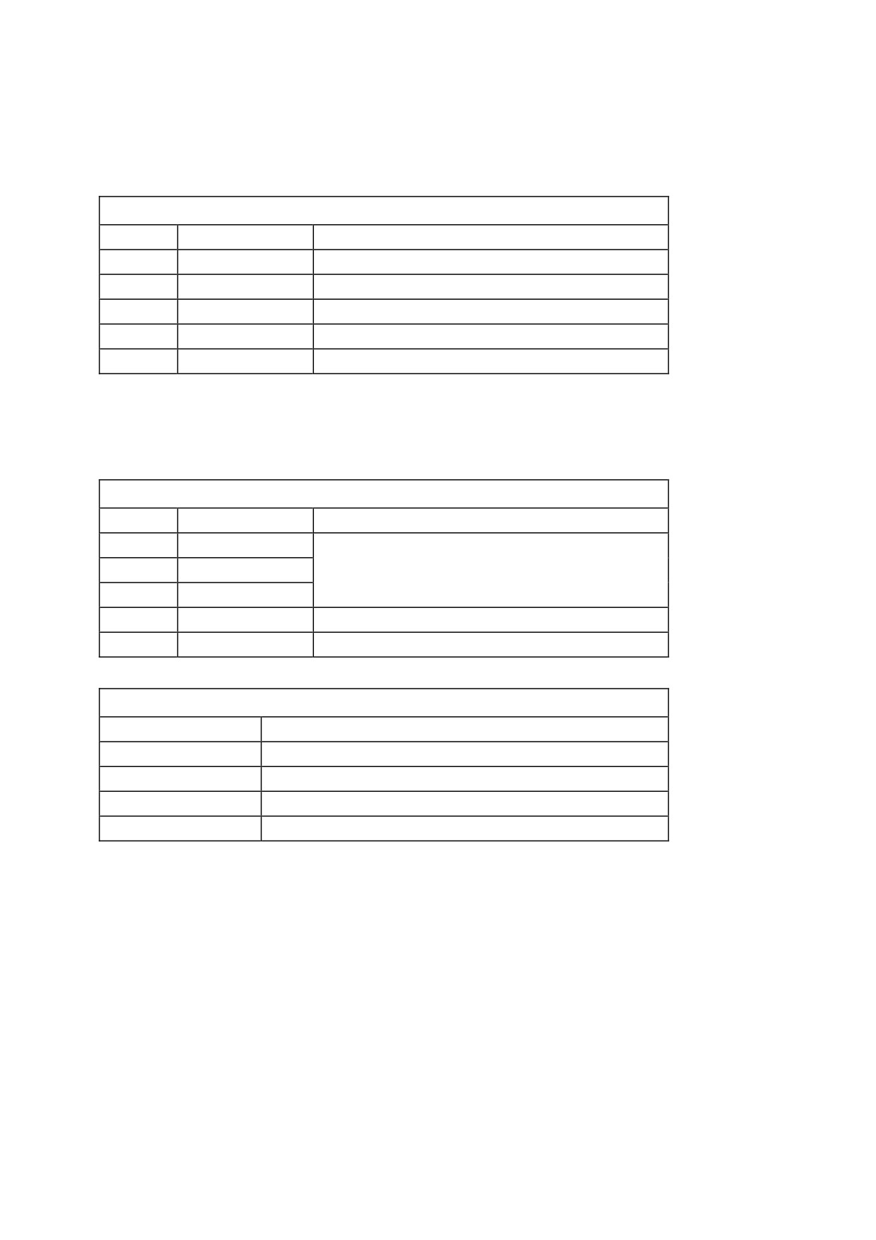
Using the incremental encoder connection, you can connect an RS-422 5V differential
auxiliary encoder. On the same connector, the voltage of the encoder itself is also available.
To program the voltage see the relative table.
Encoder SSI CONNECTION
N. Pin
Signal
Description
14
Data+
Line data trasmission positive
15
Data-
Line data trasmission negative
11
Clock+
Line clock positive
24
Clock-
Line clock negative
21
GND
0V
Using the SSI encoder connection, you can connect an absolute auxiliary encoder based on
the SSI standard. On the same connector, the voltage of the encoder itself is also available. To
program the voltage see the relative table.
Encoder CONNECTION SUPPLY
N. Pin
Signal
Description
12
+V out
13
+V out
Encoder voltage supply
25
+V out
22
GND
0V
9
GND
0V
Encoder supply setup
Voltage
Connection
5V
8V
22 - 23
12V
9 - 10
15V
9 - 10
22 - 23
By short-circuiting the pins of the connector as shown in the table, you will have a V out able
to put out 250mA which can be used to power the auxiliary encoder.
N.B.
A 220 ohm receiver-side resistor must be installeld on all differential
signals.
107
20. Motion functions concepts
This is a series of software functions for the EC-4 board that can meet all modern application
needs. The main characteristics are shown below.
Speed mode Used to generate a position profile that allows you to control the speed of the
motor with the programmed acceleration limits. More than one position profile can be
active at the same time.
Positioner
Enables incremental or absolute positioning where all positioning parameters
can be changed dynamically during the execution of the profile itself. More than one
position profile can be active at the same time.
Electrical shaft
Used to carry out the electrical shaft function. The master/slave
relationship and the engage/disengage mode are programmable. It is possible to engage
without phase recovery. With phase recovery, post- and pre-trigger functions are also
available. Disengaging can be on command, automatic by module, or on command and by
module.
Electronic cam
Provides the functions of an electronic cam. The cam profile
can be open or closed, continuous or by individual module. The cam profile can also be
changed dynamically. The cam is described with a table of any length, and more than one
cam profile can exist. The cam profile can also be described in polynomial form, and
between point pairs a cubic spline interpolation can be done.
Each profile generator can be summed with another or used as input of another, resulting in a
series of virtual axes.
108
21. Examples of applications
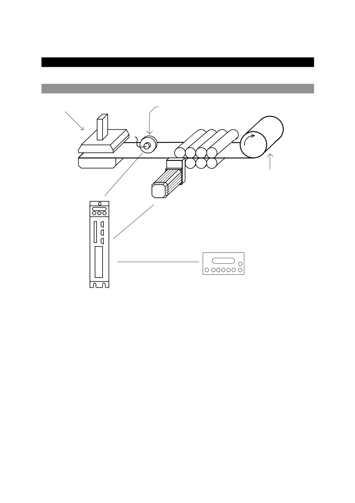
21.1. Power supply for presses
Presses
Encoder
roller
Plate
SBC Motor
Dispaly
Modbus protocol
SBC Drive + EC4 expansion board
Positioning value control on external encoder or resolver
Press control
Rollers closed signal
Sheet signal
99 process types
For each process, you can program: level, operating speed, and acceleration
Jog back and forward
Connection with display to program the system directly
109
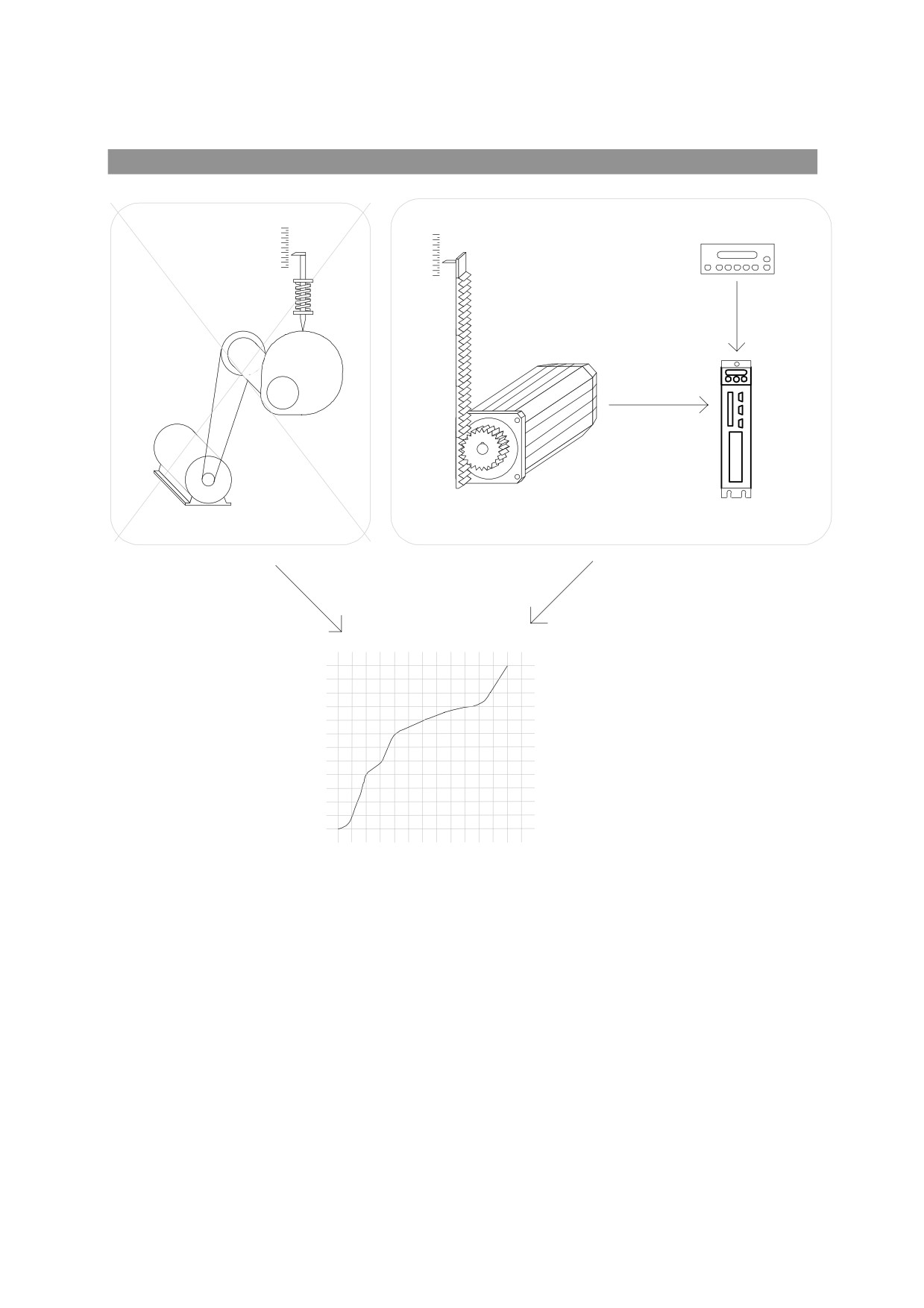
21.2. Electronic cam
Max
Max
Dispaly
Min
Min
SBC Motor
SBC Driver + EC4 expansion board
Slave
270
180
90
0
0
90
180
270
360
Master
Homing function
Electronic cam which can be stored on the EC-4 board
Hold function to disengage and reengage the cam at a given master position
An external device can be connected using Profibus DB, DeviceNet, or RS-422 serial interface
in order change cam points in real time.
110
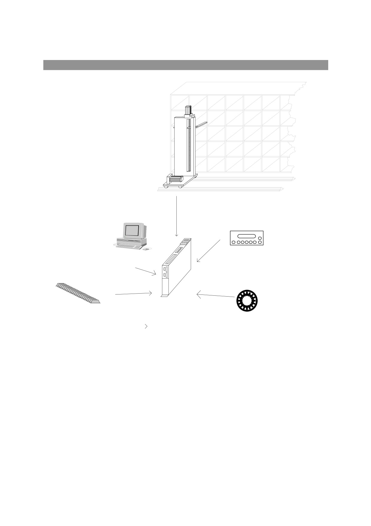
21.3. Positioner with 250 preset levels
SBC Motor - Vertical axe
SBC Motor - Horizontal axe
Display
Profibus DP connection
to control device
250 preset levels
incremental or absolute Encoder
Positioning value control on incremental or absolute SSI encoder or resolver
250 levels can be stored
Jog back and forward
A display can be connected to program and monitor the positioner
Profibus-DP interface to manage the system
111
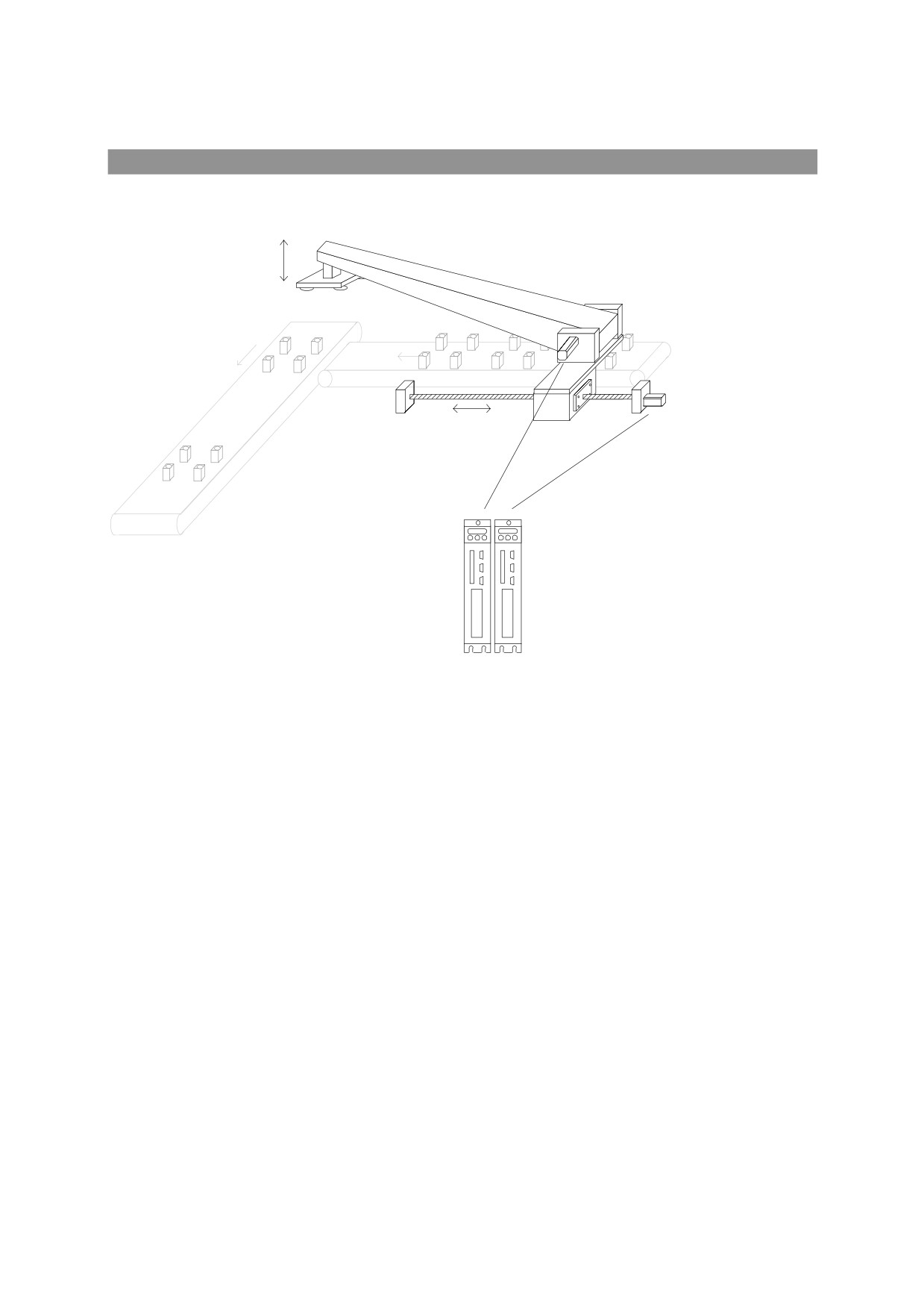
21.4. Two-axis extractor
Extraction axe
Teaching axe
Teaching axe motor
Extraction axe motor
SBC Drive + EC4 expansione board
Positioning value control on external incremental encoder, SSI encoder, or resolver
Management of the control signals for the unloading line
Management of the control signals for the extractor device
Programmable feed and unload times
Ability to program n formats
For each process, you can program:
o feed and unload levels
o rapid approach values for extraction
o Speed and acceleration of loaded extractor
o Speed and acceleration of empty extractor
Jog back and forward
Ability to connect a display to program the system directly
112
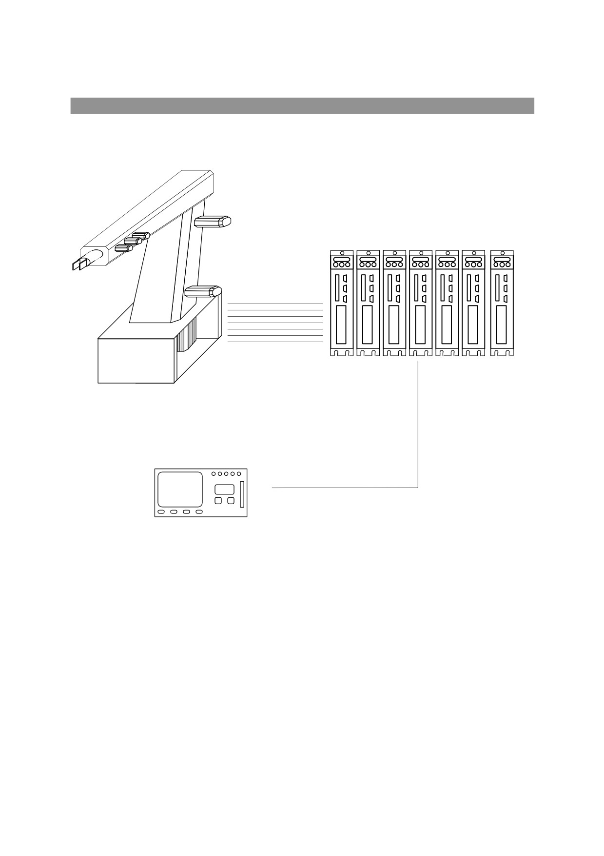
21.5. Vertical robot
Vertical Robot
SBC Driver + EC4 expansion board
External Control
CAN BUS line
-
Interconnection of seven axes by SBC CAN BUS with ring management of space within
control
113
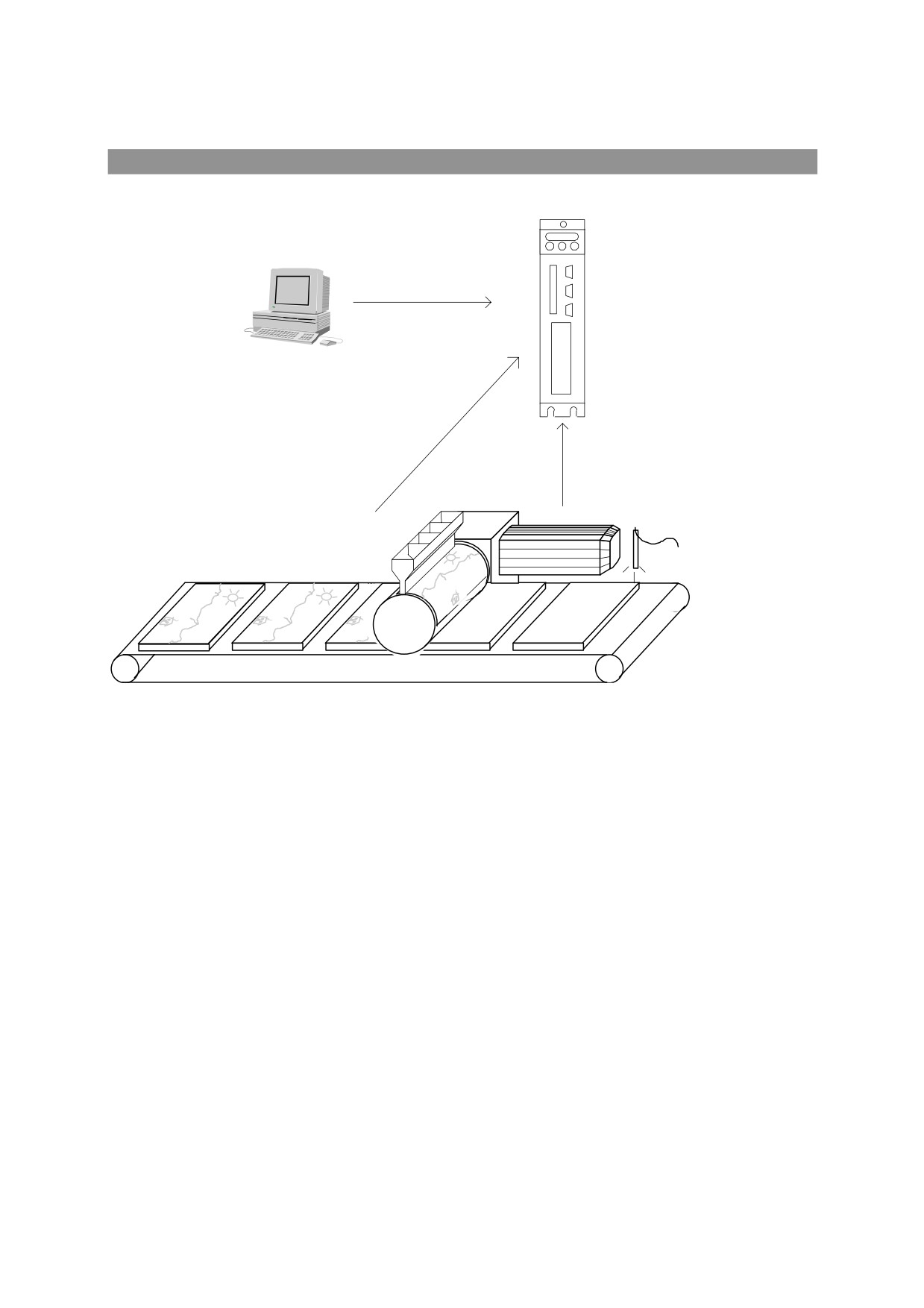
21.6. Continuous press
Serial connection and
monitorin system
HPD + EC4 expansion board
SBC Motor
Laser
press roller
On-the-fly correction of press module synchronism
Serial control of motion parameters
114
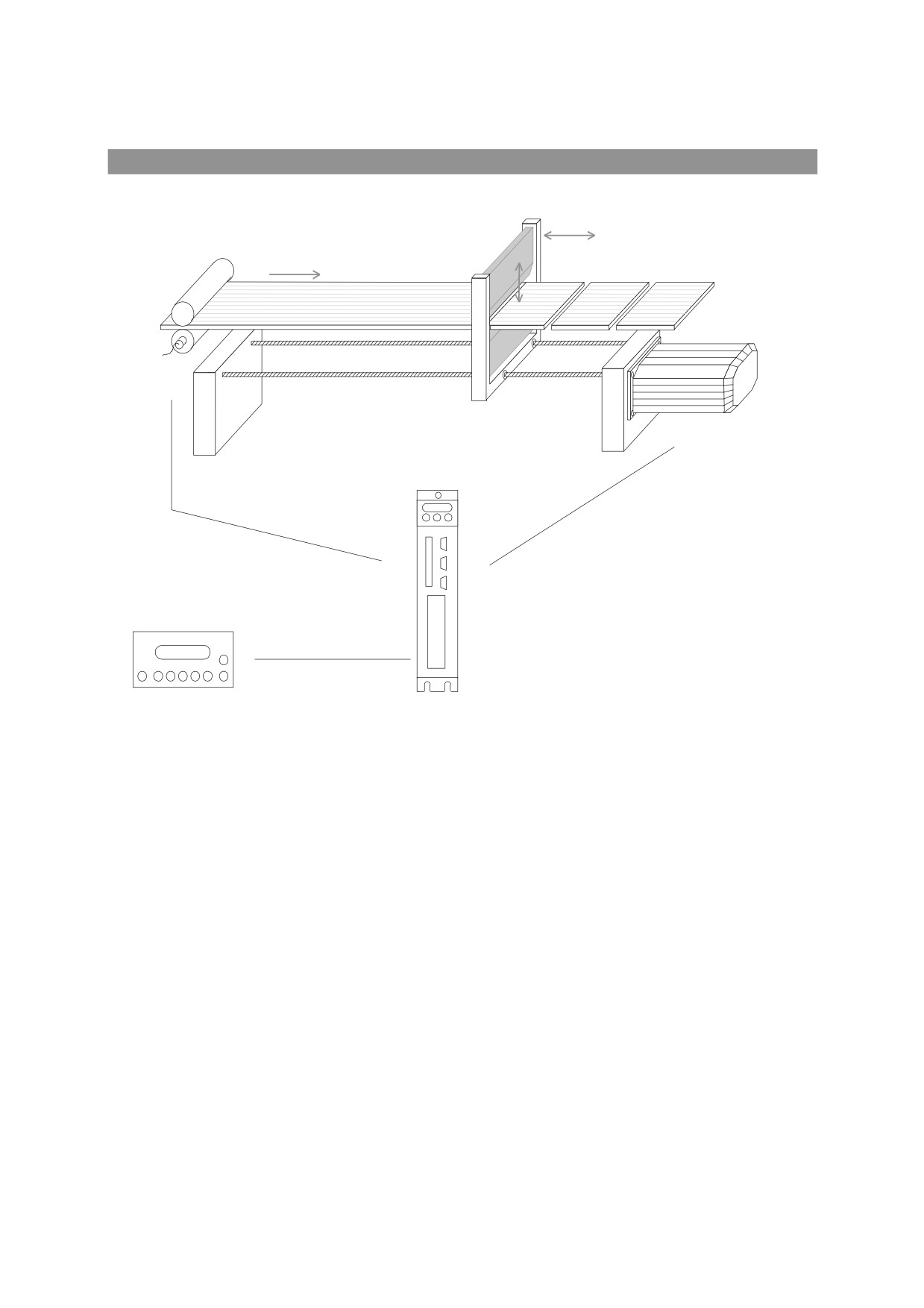
21.7. On the fly cutting
Encoder
SBC Motor
SBC Drive + EC4 expansion board
Dispaly
Modbus protocol
Engage electric shaft with the line with phase recovery
Ability to program n formats
For each process, you can program:
o number of consecutive pieces
o return speed in rapid mode.
Jog back and forward
Ability to connect a display to program the system directly
115
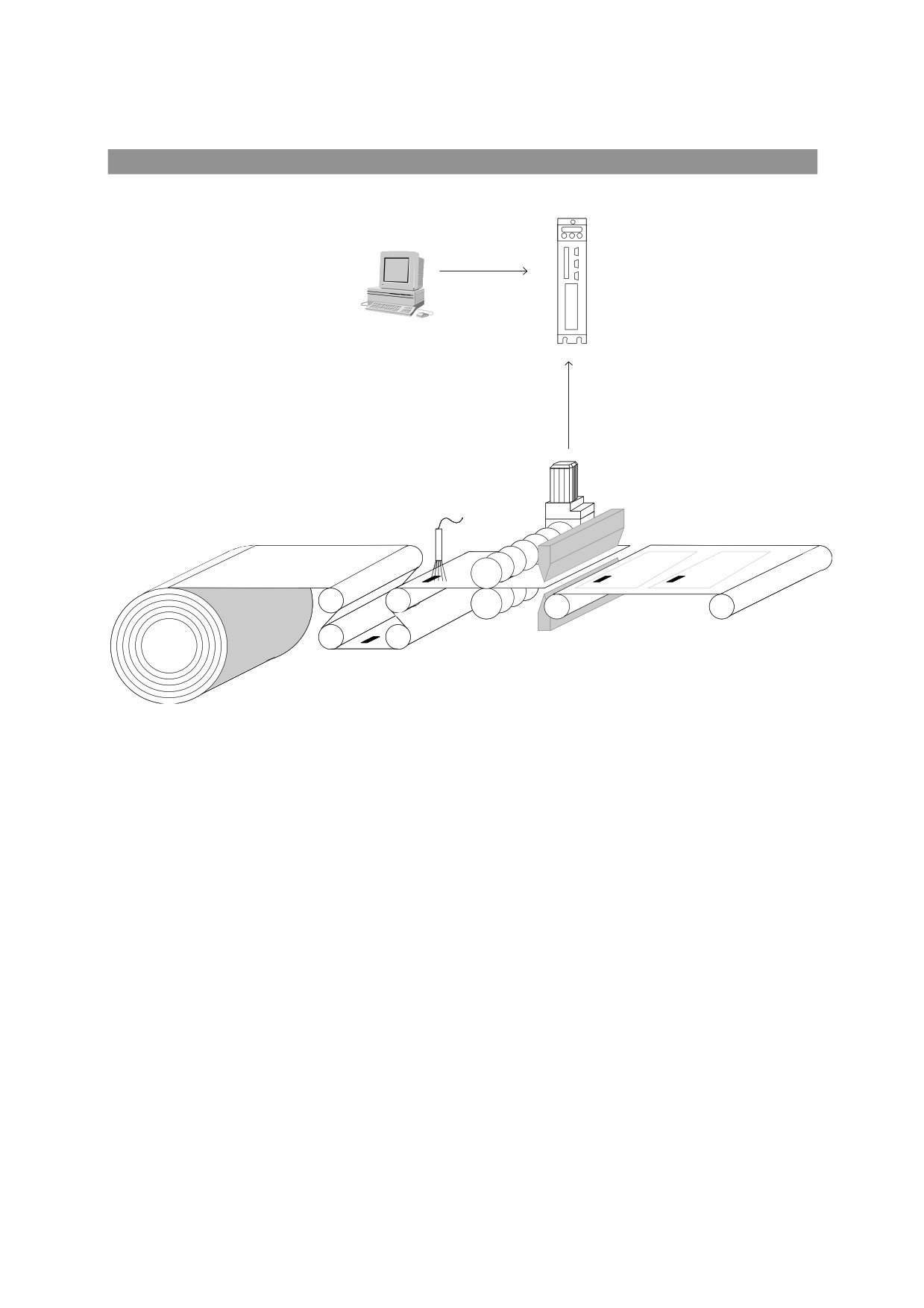
21.8. Heat sealer
serial connection to
monitoring system
HPD + EC4 expansione board
SBC Motor
Photoelectric cell.
rolling press
Heat sealer
On-the-fly correction of bag size
Serial control of motion parameters
116
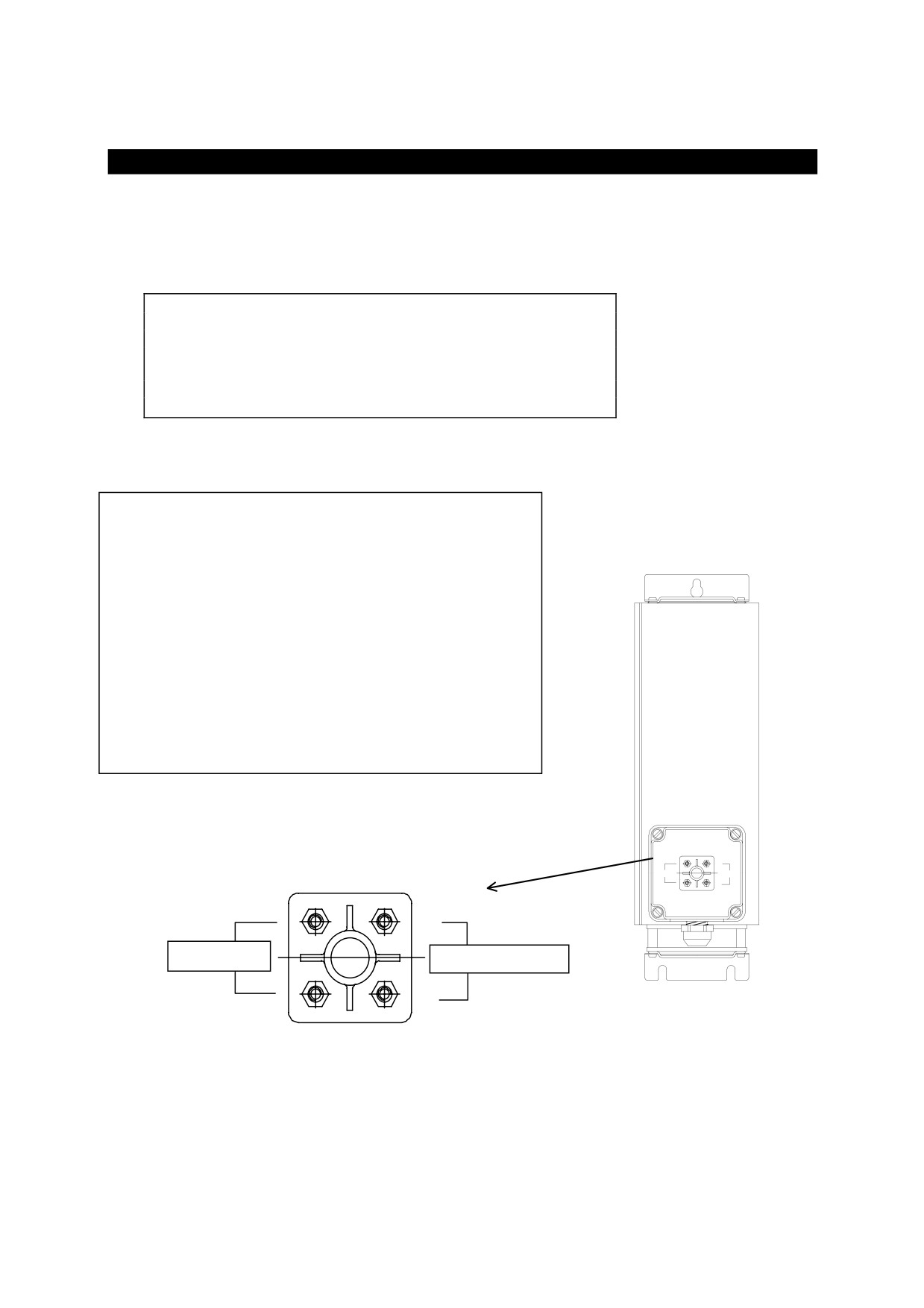
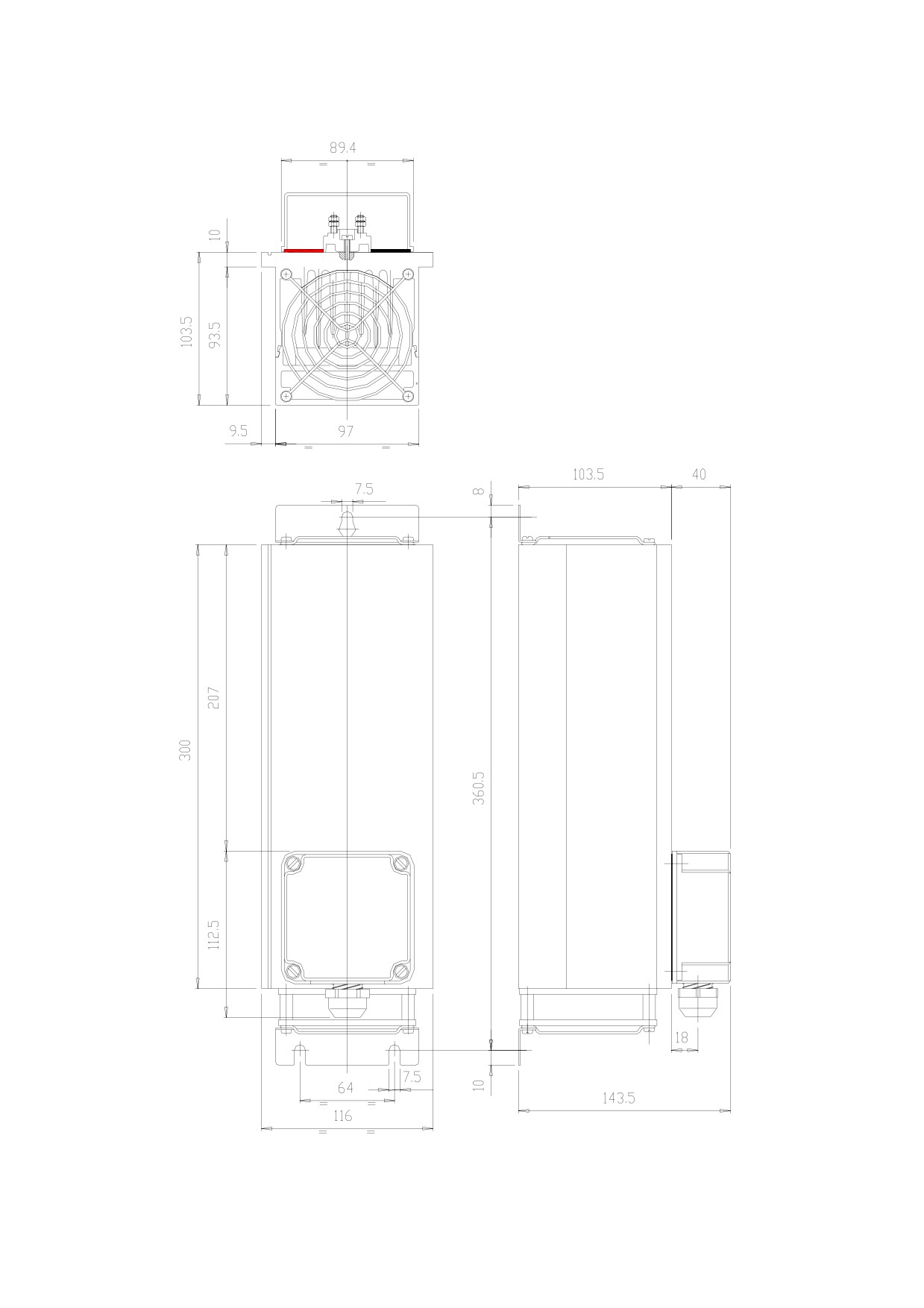
22. Appendix M: external bracking modul
TECHNICAL CHARACTERISTICS
Resistance value:
RFE1 = 40 ohm, RFE2 = 27 ohm
IP protection
20
Max power dissipated
1000 W
Max ambient temperature
45° C
Delta T
90° C
Weight
2,5 Kg
Ventilation power supply
24 V=
INSTALLATION
The RFE1 or
2 breaking module must be installed
vertically as shown. A four-pole 4mm2 cable must be
used for the connection.
The 24v power supply used for the ventilator can cause
disturbances. It is therefore a good idea not to use the
same power line for electronic devices. The cable
should not be longer than 4m. For the connection to the
drive, see the related chapter in the converter manual
and use a 30A thermo-magnetic switch.
Terminal pins REF1
-
resistenza
24V dc Vent.
+
-
resistance
24Vdc ventilation
+
117
118
23. Appendix N application description form
In order to develop our products in co-ordination with user’s needs, we are most
interested to learn about your HPD application. Please fill in this form and return it to
us. This will also enable us to tailor our technical support to your individual
requirements.
Fill in these forms in full and keep them with the machine technical
documentation to facilitate maintenance.
to:
Parker Hannifin S.p.A. - Divisione S.B.C. / ITALY
R & D department
fax:
+39-2-66016116
CUSTOMER name
Contact name
Tel.
Fax.
MODEL
HPD 2
HPD 5
HPD 8
HPD 16
SERIAL NUMBER
_ _ _ _ _ _ _
MOTOR MODEL
MOTOR SERIAL NUMBER
OPERATING VOLTAGE
_ _ _ V
FIRST HPD APPLICATION?
YES
NO
MACHINE TYPE
TASK PERFORMED BY AMPLIFIER
COMMENTS
FUNCTIONS USED
EXTERNAL BRAKING
MAINS FILTERS
ENCODER IN
BACK-UP
LOW VOLTAGE FUNCTION
ENCODER OUT
PARALLEL BUS
INTERNAL PLC
MOTOR COILS
SERIAL LINE
AMPLIFIER CONTROLLED BY
MAKE
MODEL
NUMERICAL CONTROL
PLC
SINGLE AXIS CARD
MASTER/SLAVE CARD
OTHER
119

AMPLIFIER PROGRAMMING
Pr
value
Pr
value
Pr
value
Pr
value
1
31
42.5
70.6
2
32
42.6
70.7
3
33
42.7
70.8
4
34
50
70.9
5
39
51
70.10
8
40.0
52
70.11
9
40.1
53
70.12
10
40.2
54
70.13
11
40.3
55
70.14
12
40.4
56
70.15
13
40.5
57
80
14
40.6
58
81
15
40.7
59
82
16
40.8
60:61
83
17
40.9
62:63
84
18
40.10
64:65
85
19
40.11
66:67
86
23
40.12
68:69
87
24
40.13
70.0
88
25
40.14
70.1
89
26
40.15
70.2
99.6
27
42.0
70.3
99.7
29
42.1
70.4
99.8
30
42.2
70.5
99.13
IF YOU USE AN INTERNAL PLC PROGRAM OTHER THAN THE DEFAULT
PROGRAM, PLEASE ENCLOSE THE LISTING.
In 0
In 16
In 32
In 48
In 1
In 17
In 33
In 49
In 2
In 18
In 34
In 50
In 3
In 19
In 35
In 51
In 4
In 20
In 36
In 52
In 5
In 21
In 37
In 53
In 6
In 22
In 38
In 54
In 7
In 23
In 39
In 55
In 8
In 24
In 40
In 56
In 9
In 25
In 41
In 57
In 10
In 26
In 42
In 58
In 11
In 27
In 43
In 59
In 12
In 28
In 44
In 60
In 13
In 29
In 45
In 61
In 14
In 30
In 46
In 62
In 15
In 31
In 47
In 63
120
24. Rervision history of the User’s Manual
Rev. 8.2
January 2004
-
sizing resistance of braking, sketch of connection
-
procedure low tension
-
given adjournment from the addendum
-
appendix on form of external braking from 1kW
-
adjournment charts, graphic, notes and name of the group
-
data of new series: drive HPD20N and HPD24N
-
adjournment sketch of filters
-
appendix L, M, N, O, examples for some applications, motion
-
adjournment sketch of serial connection rs485, rs422
-
revision history of the manual
rev 8.3
February 2004
-
correction to resolver cable
-
low voltage procedure
-
external braking resistance
-
external braking module
-
adjournment by addendum
-
EC4 expansion board
-
Profibus connector
-
Canbus connector
-
Digital I/O
-
Encoder and serial link
-
Alarms
-
Examples of application
-
Adjournment tables and drawings
-
Pr37 removed
-
Adjournment sketch RS485-RS422
-
Filters and motors appendixes removed
Rev8.4
March 2004
-
correction to Pr34
Rev8.5
November 2004
-
declaration of conformity
-
note about restricted sales
-
Adjournment sketch braking resistor
-
Connection diagrams for frequency/direction signals
For other information log into website www.sbcelettronica.com. Arranges to the manual data can be made by
the manufacturer without advance notice. The data shown in the manual correspond to the specifications
relating to the revision date
121