Parker HPD N (HPD2N, HPD5N, HPD8N, HPD16N, HPD20N,HPD24N). User’s manual (2004) - page 3
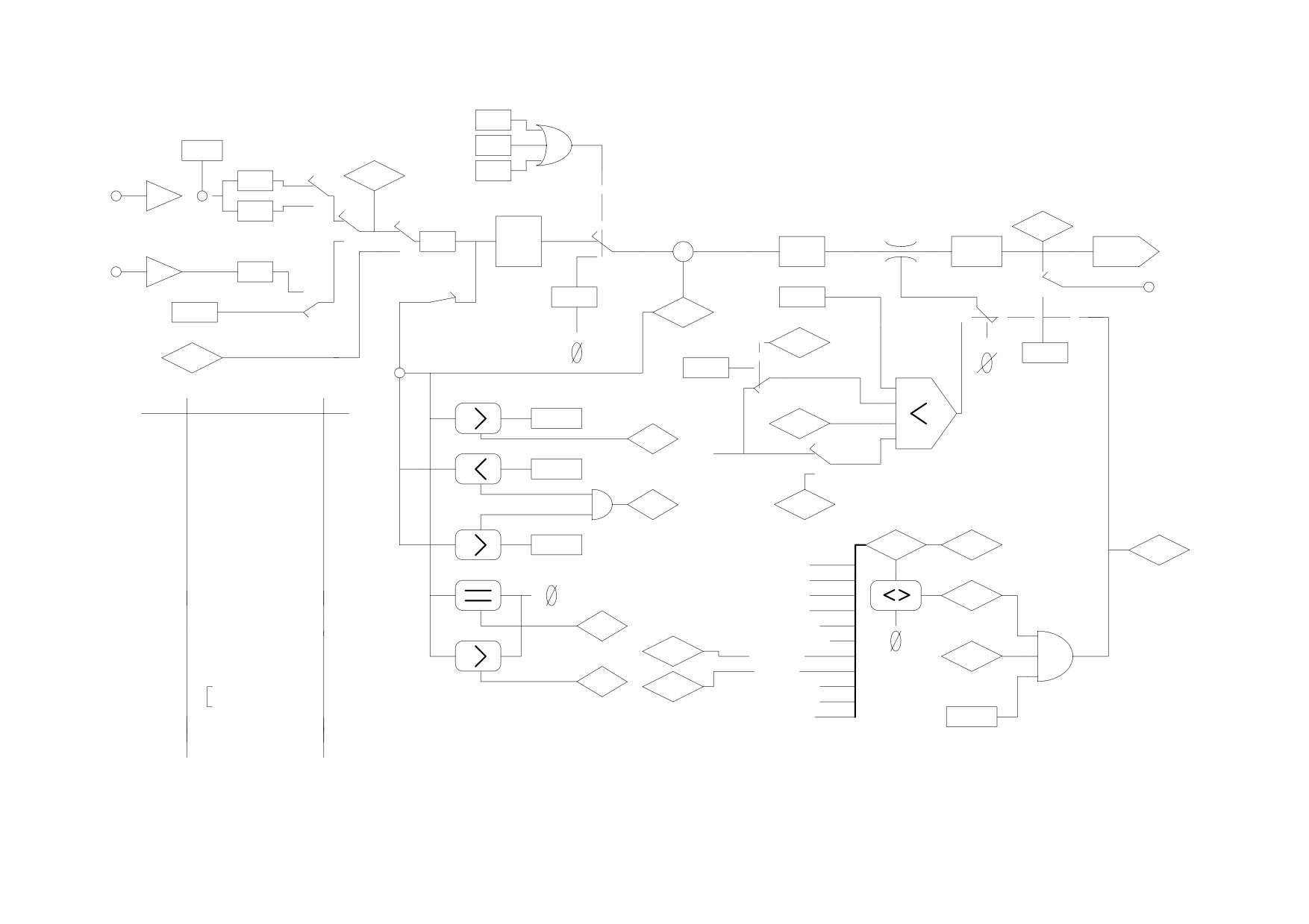
left-sw
b40.4
offset
HIGH PERFORMANCE DRIVE
right-sw
b40.5
Pr 1
full scale
main ref.
ref. 1
stop
b40.6
Pr 7
-
Pr 2
b40.0
MAIN BLOCK DIAGRAM
A/D
+
torque demand
ramps values
Pr 3
band-width
full scale
S/H
Pr 8
speed control
limitator
Pr 35
b40.12
ref. 2
Pr 9
b40.2
b40.3
torque
Pr 10
+
Pr 16
max fq ref.
Pr 18
Pr 11
Pr 17
demand
-
F/D
Pr 4
user current limit
internal reference
ramp
b40.11
Pr 12
Pr 19
value
analog out
Pr 5
b40.13
b40.7
Pr
0
thermal image limit
reserved reference
motor speed
b41.11
Pr
6
-
Pr 38
+
Pr 33
Vout aux
rated current
over
reserved current limit
Param.
DESCRIPTION
R/W
over speed
Pr 13
Pr 21
Pr 25
SOFTWARE RELEASE
N
b 41.0
Pr 26
BAUD RATE
Y
max
high
Pr 27
SERIAL LINK ADDRESS
Y
Pr 14
b40.8
Pr 28
SHAFT POSITION
N
at speed
Pr 29
MOTOR POLES
Y
Pr 30
RES. PHASE SHIFT
Y
b 41.1
Pr 22
trip code
Pr 31
OPERATING MODE
Y
present
last
low
aux reference
drive enabled
Pr 32
RATED SPEED
Y
Pr 15
Pr 23
Pr 24
Pr 36
I2T ACCUMOLATOR
N
b41.12
over voltage
Pr 37
BRAKE RESISTOR USE
N
drive ok
under voltage
Pr 20
DC BUS VOLTAGE
N
over current
Pr 39
PHASE ADVANCE
Y
b41.4
zero speed
resolver break
Pr 34
GAIN FOR TACHO
motor over temp.
hardware
B42.0
b 41.2
enable
power stage over temp
B42.1
ENCODER OUT RESOL.
Y
b 41.7
external trip
B42.2
forward
b41.5
aux. trip
B42.5
QUADRATURE / FD
Y
b 41.3
output short circuit
B41.14
EXTERNAL OPM
N
b 41.8
software
PLC check-sum
enable
B41.15
FLAGS
PAR. check-sum
B41.6
PRE ALARM
N
b40.9
B40.1
VIBRATION STOP.
Y
B40.10
LOW VOLTAGE OP.
Y
53
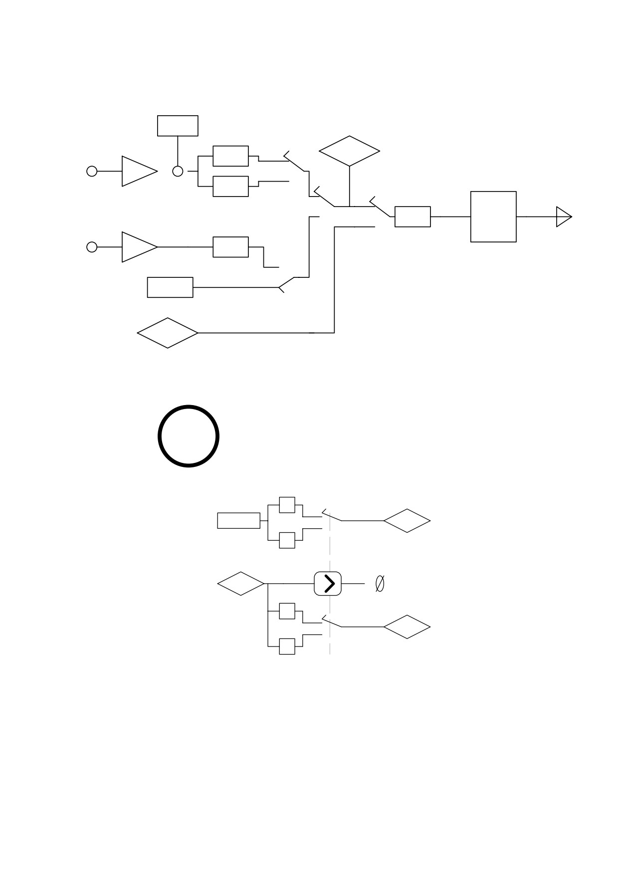
REFERENCE SELECTION
offset
Pr 1
full scale
main ref.
ref. 1
Pr 7
-
Pr 2
b40.0
+
A/D
ramps values
Pr 3
S/H
full scale
Pr 8
b40.12
ref. 2
Pr 9
b40.2
b40.3
Pr 10
max fq ref.
Pr 11
F/D
Pr 4
internal reference
Pr 5
b40.13
reserved reference
Pr
6
TORQUE CONTROL
1
OPERATING MODE
1
Pr 50
Pr 6
max speed
-1
reserved reference
Pr 7
main ref
1
Pr 21
reserved
-1
current limit
54
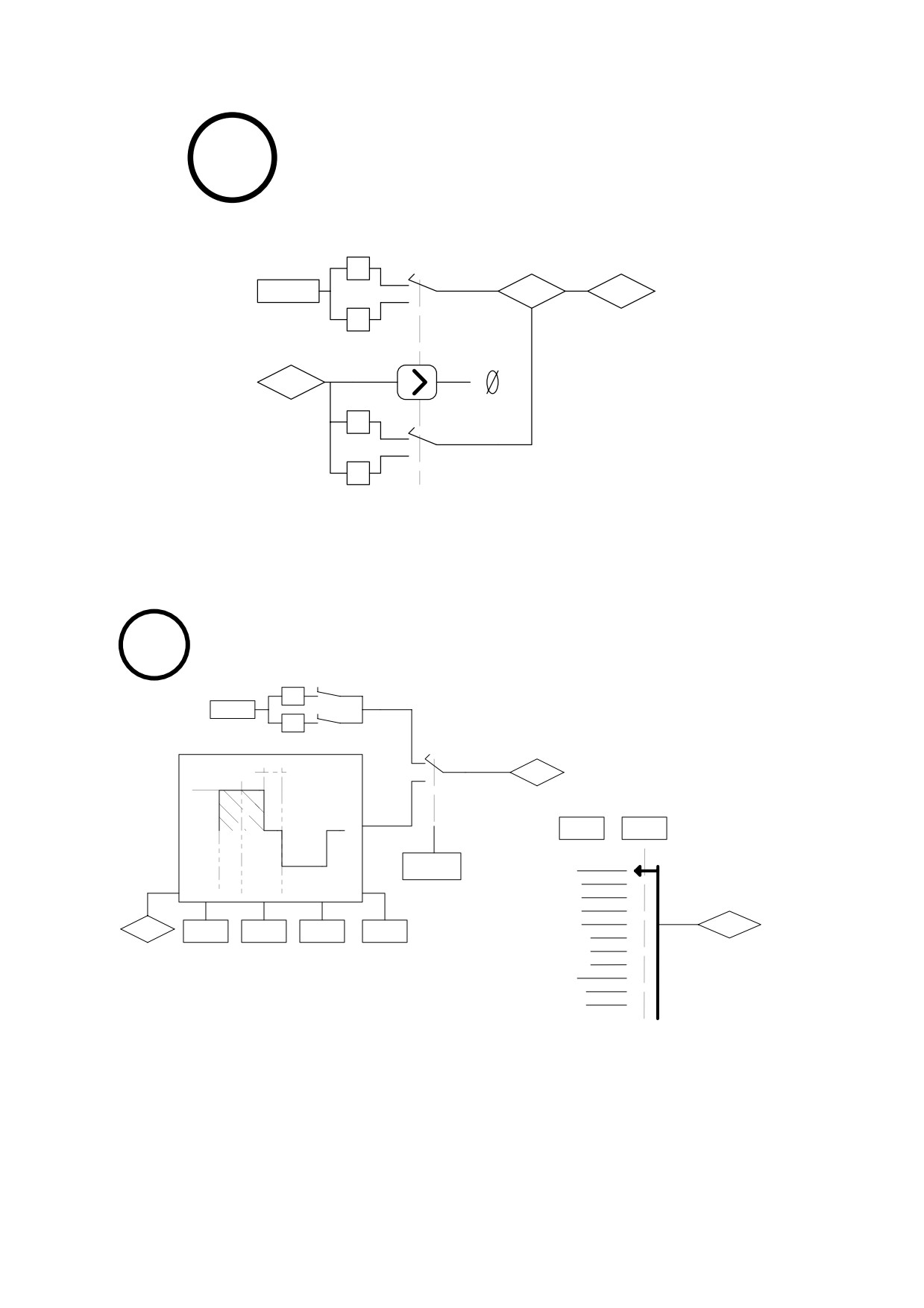
ACCELERATION CONTROL
2
OPERATING MODE
ramps
1
Pr 50
Pr 55
Pr 6
max speed
-1
reserved reference
Pr 7
main ref
1
-1
8
MAINTENANCE & COMMISSIONING
manual speed
1
b70.1
Pr 50
OPERATING MODE
-1
b70.2
profile generator
T
Pr 6
V
reserved
reference
wiring test
selector pos.
A
b70.3
Pr 57
0
b70.0
error code
1
1
2
3
# motor poles
start/stop
2
resolver phase
3
value
reference input
4
aux analog input
Pr 56
Pr 55
Pr 51
Pr 52
Pr 53
Pr 54
5
digital input status 1
6
err. std dev. test speed
test stroke starting point
delay
digital input status 2
7
encoder in counter
8
bus voltage
9
offset compensation U
10
offset compensation V
55
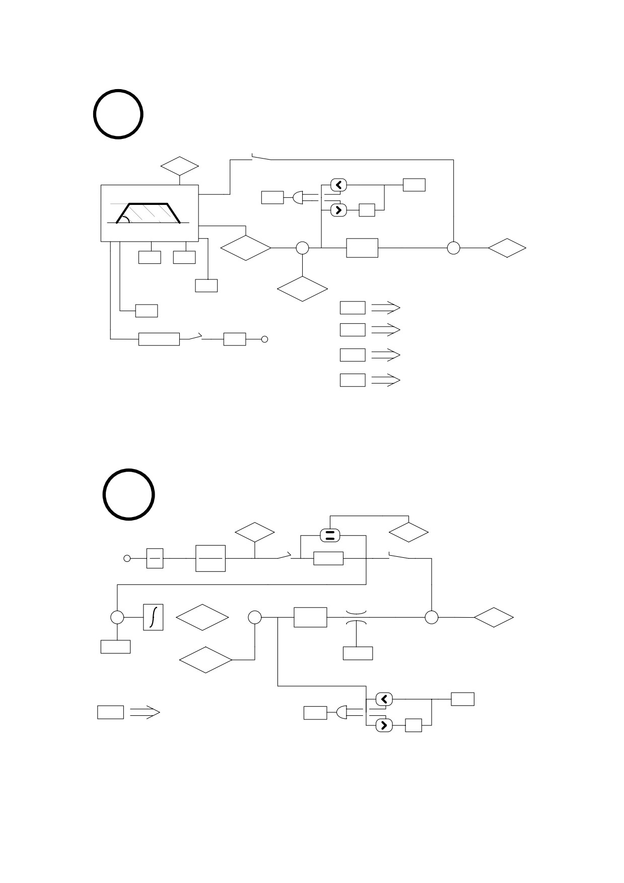
TRAPEZOIDAL POSITIONER
9
OPERATING MODE
in progress
b70.6
b70.7
profile generator
feed
Pr 56
forward
servo error
V
b70.5
window
servo error
- 1
A IQ
proportional
reserved
gain
reference
+
+
+
Pr 61:Pr60
Pr 57
Pr 6
Pr 51
Pr 52
-
ramps steady time
target position
speed
b70.8
Pr 63:Pr62
profile on
reset 1
reverse/forward
motor position
b70.10
target position = motor position = 0
b70.4
pulses
b70.11
target position = motor position = shaft position
Pr 65:Pr 64
Pr 50
reset 2
b70.9
incremental
steps for pulse
position
b70.12
target position = motor position
reset 3
b70.2
incremental position Pr 65:Pr 64 = 0
reset 4
DIGITAL LOCK
10
OPERATING MODE
master speed
Pr 55
b70.2
ratio
encoder
locked
master
d
Pr 51
b70.6
Pr 52
dt
b70.8
Pr 53
ramp
feed
forward
proportional
gain
+
+
+
+
Pr 61:Pr60
Pr 57
Pr 6
-
+
reserved reference
target position
Pr 58
Pr 50
slip
Pr 63:Pr62
speed
max regulator
speed
motor position
reset 1
Pr 56
servo error
b70.10
target position = motor position = 0
b70.5
window
servo error
- 1
56
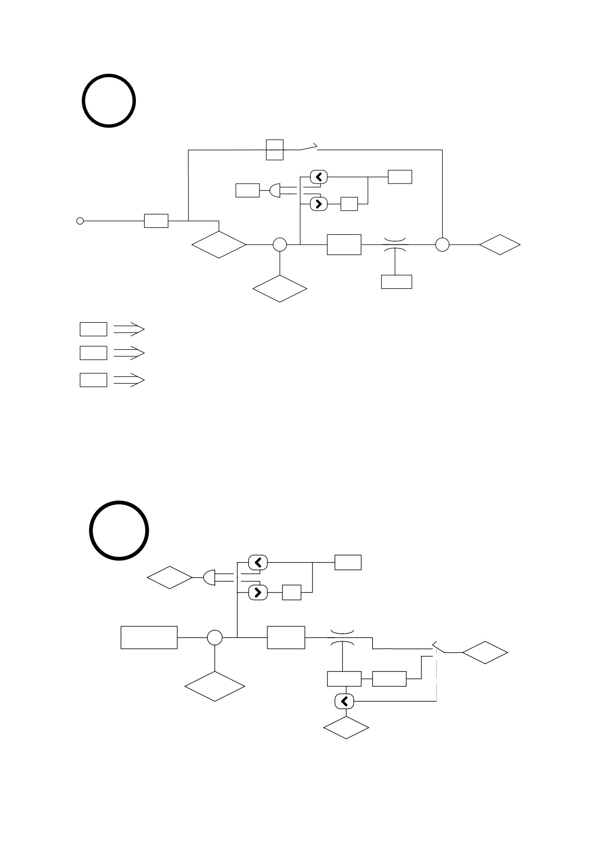
STEPPER LIKE
11
OPERATING MODE
feed forward
d
dt
b70.6
Pr 56
servo error
b70.5
window
servo error
- 1
k mul
pulses input
Pr 51
proportional
gain
+
+
+
Pr 61:Pr60
Pr 57
Pr 6
-
reserved reference
target position
Pr 50
Pr 63:Pr62
max regulator
speed
motor position
reset 1
b70.10
target position = motor position = 0
b70.11
target position = motor position = shaft position
reset 2
b70.12
target position = motor position
reset 3
SPINDLE ORIENTATION
OPERATING MODE
12
Pr 56
oriented
b70.5
window
not oriented
- 1
proportional
gain
+
Pr 54
Pr 57
-
Pr 6
target position
reserved reference
max regulator
Pr 50
Pr 52
speed
Pr 28
ramps
shaft position
motor
speed
Pr 0
57
4.8. Digital input and output programming
4.8.1. Pico-PLC
The internal pico-PLC makes it possible to connect peripheral systems (inputs/outputs) to
the parametric system of the HPD drive. The PLC can be used to copy a digital input into a bit
parameter, copy a bit parameter into a digital output and perform mathematical and boolean
calculations. The PLC program must be entered as a list of instructions from the keypad;
alternatively the PLC can be programmed with the ladder diagram system using a PC on the
serial line with an interface such as Pcbrush. Default parameterisation (b99.12) provides a
PLC program (see appendix G) designed to fill the requirements of the broadest possible
range of applications, therefore it is not necessary to reprogram the PLC in the majority of
cases.
Main features of the PLC:
Program steps
64
scan time
6.144 ms
timers
2
instructions
15
stack depth
1
mathematic operations
16 / 32 bits
fast inputs (fast copy)
3 - (512 µs)
PLC PARAMETERS
Pr71 Constant value = -1. Double word.
Pr72 Constant value = 0. Double word.
Pr73 Constant value = 1. Double word.
Pr74 Constant value = 2. Double word.
Pr75 Constant value = 10. Double word.
Pr76 Constant value = 100. Double word.
Pr77 Constant value = 1000. Double word.
Pr78 Constant value = 1024. Double word.
Pr79 Constant value = 4096. Double word.
Pr80 Free parameter. Parameter with save facility at user’s disposal (word).
Pr81 Free parameter. Parameter with save facility at user’s disposal (word).
Pr82 Free parameter. Parameter with save facility at user’s disposal (word).
Pr83 Free parameter. Parameter with save facility at user’s disposal (word).
Pr84 Free parameter. Parameter with save facility at user’s disposal (word).
Pr85 Free parameter. Parameter with save facility at user’s disposal (word).
Pr86 Free parameter. Parameter with save facility at user’s disposal (word).
Pr87 Free parameter. Parameter with save facility at user’s disposal (word).
Pr88 Free parameter. Parameter with save facility at user’s disposal (word).
Pr89 Free parameter. Parameter with save facility at user’s disposal (word).
58
b90.X Digital input X status. If X is greater than 7, parameter with save facility at user’s
disposal (b90.0 = drive enable).
b91.Y Digital input Y status. If Y is greater than 7, parameter with save facility at user’s
disposal. Parameter Pb91 is not saved at power up and is definitely at zero.
Pr92 First PLC timer. Every 6.144 ms if Pr92 is not at 0 the timer is decreased, if set to
zero b99.0 is set at 1.
Pr93 Second PLC timer. Every 6.144 ms if Pr93 is not at 0 the timer is decreased, if set
to zero b99.1 is set to 1.
b94.0 Forces a double word formatted operation. When the drive is powered up this
parameter is on zero. If it is on one, the first mathematical operation of the pico-PLC
is executed setting the three operands as double word type; after the operation is
executed b94.0 is automatically set to zero.
If Pr60..Pr68 are utilised, double word formatting is automatic (see text).
b94.5 Disables the first fast input (b94.5=0). Set to zero at power-up.
b94.6 Disables the second fast input (b94.6=0). Set to zero at power-up.
b94.7 Disables the third fast input (b94.7=0). Set to zero at power-up.
b99.0 First timer status. At 1 if Pr92 = 0
b99.1 Second timer status. At 1 if Pr93 = 0
b99.2 At 1 if the result of the last PLC operation is negative.
b99.3 At 1 if the result of the last PLC operation is zero.
b99.13 PLC status. Default=1. If set to 1 the PLC program is executed, if on zero the
program is not executed and modification of PLC instructions is enabled.
59
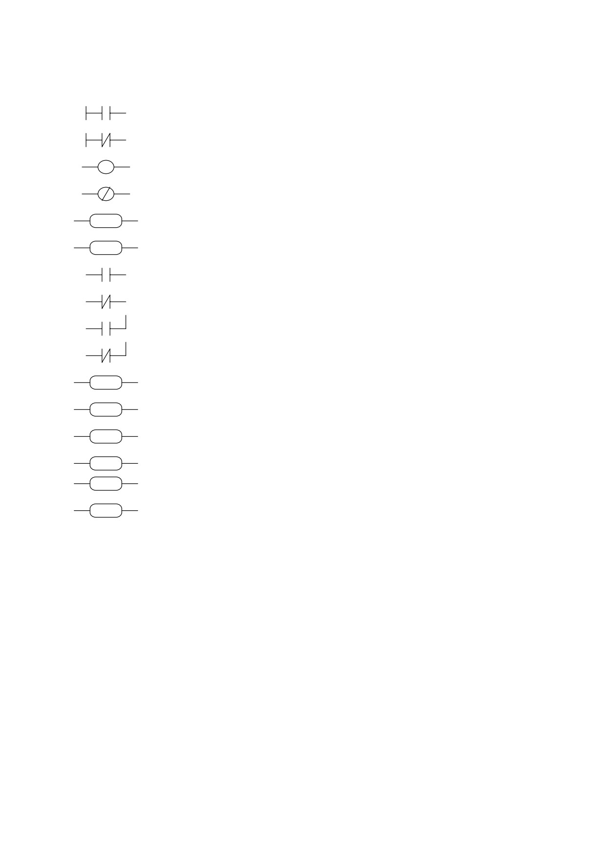
PLC INSTRUCTIONS
Pa.y
LD
Pa.y
load bit y of parameter Pa in the stack
Pa.y
LDN
Pa,y
load inverted bit y of parameter Pa in the stack
Pa.y
OUT
Pa,y
set bit y of parameter Pa to the value loaded in the stack
Pa.y
OUTN Pa,y
set bit y of parameter Pa to the stack value and invert it
Pa.y
SET
SET
Pa,y
if stack is at 1, set bit y of parameter Pa to 1
Pa.y
RES
Pa,y
if stack is at 1, set bit y of parameter Pa to zero
RST
AND
Pa,y
the bit loaded into the stack assumes the result of the
Pa.y
logical AND operation between itself and bit y of
parameter Pa
Pa.y
ANDN Pa,y
the stack bit assumes the result of the logical AND between
itself and inverted bit y of parameter Pa
Pa.y
OR
Pa,y
the bit loaded into the stack assumes the result of the OR
between itself and bit y of parameter Pa
Pa.y
ORN
Pa,y
the stack bit assumes the result of the OR between itself
and inverted bit y of parameter Pa
Pa Pb Pc
ADD
Pa, Pb, Pc if stack bit is at 1, parameter sum operation is executed,
ADD
therefore: Pc = Pa + Pb
Pa Pb Pc
SUB
Pa, Pb, Pc if stack bit is at 1, subtraction operation is executed on
SUB
parameters, therefore: Pc = Pa - Pb
Pa Pb Pc
MUL
Pa, Pb, Pc if stack bit is at 1, multiplication operation is executed on
MUL
parameters, therefore: Pc = Pa ⋅ Pb
Pa Pb Pc
DIV
Pa, Pb, Pc if stack bit is at 1, division operation is executed on the
DIV
parameters, therefore: Pc = Pa / Pb
END
program end
END
Pa.y
FIN
y,
0/1
fast scanning input
FIN
60

OPERATIONAL DESCRIPTION
The pico-PLC program is scanned every 6.144 msec; at each sampling first the inputs are
read, then the two timers are updated (Pr92 Pr93 b99.0 and b99.1), the user program is
scanned, and finally the outputs are updated. Therefore, reading of the inputs and output
updates can deviate temporally by up to 6.144 ms with respect to the physical event.
All pico-PLC instructions with the exception of mathematical instructions, operate on
single bits; moreover, available stack depth is a single bit.
Instruction LD (LDN) loads the bit defined as operand into the stack, while all other
logical instructions operate on the stack. Mathematical operations are executed only if the
stack bit is at 1.
The following logic operations truth tables are provided for the user’s convenience:
logical AND operations
logical OR operations
bit A
bit B
result
bit A
bit B
result
0
0
0
0
0
0
0
1
0
0
1
1
1
0
0
1
0
1
1
1
1
1
1
1
The relative inverted ANDN and ORN operations follow the same logic, except they use
the inverted value of the specified bit.
There are 8 bits with save facility from b90.8 to b90.15 reserved for the PLC; a further 8
bits from b91.8 to b91.15 are available for the PLC; these are not stored and are always at
zero at drive power-up.
Also 10 word parameters are reserved, specifically from Pr80 to Pr89 with save facility
and option for use as 5 double word parameters. For mathematical operations the pico-PLC
has 9 constants available, from Pr71 to Pr79 selected from those that are most frequently
utilised in standard applications.
When using mathematical instructions (ADD, SUB, MUL, DIV) note that operators are
assumed as words with their relative signs. If a double word operation is necessary, parameter
b94.0 must be set to 1 before the operation; after the operation the PLC will automatically set
the bit to zero. Parameters Pr60...Pr69 are considered as double words so an operation like
[ADD 71 72 64] will write the result -1 in the double word Pr64:65 without having to set
b94.0=1 before the operation. If Pr80=-1 and Pr81=0, the operation [ADD 80 72 64] will have
the result Pr64:65=-1, while the same operation performed with b94.0=1 will assume Pr81 as
the high part of the double word Pr80:81 so the result will be Pr64:65=65535. In the first case,
therefore, operands other than Pr60...Pr69 will be treated as words, while in the second case
they will be treated as double words.
Note that in mathematical operations on double words, operands and results are defined as
follows: the operand parameter defines the least significant part while the most significant
part is represented by the word with the next serial address (see chapter Serial addresses and
parameter lengths). Parameters from Pr50 to Pr69 and from Pr80 to Pr89 are successive.
61
At the completion of each mathematical operation b99.2 is set to 0 if the result is positive,
and to 1 if the result is negative; likewise, b99.3=0 if the result is zero and b99.3=1 if it is
different from zero. These settings remain valid until the next mathematical operation is
performed (the operation is executed only if the stack bit is equal to one). A mathematical
operation can be performed, setting the result in one of the constant parameters (Pr71...Pr79)
in order to set bits b99.2 and b99.3.
In the case of the DIV operation, if it is executed on a double word the most significant
part of the result contains the rest of the division, i.e. if you set b94.0=1 and perform [DIV 79
77 80] the result will be Pr80=4 and Pr81=96.
Note that parameters Pr23, Pr24, Pr25, Pr26, Pr27, Pr29, Pr31 and Pr34 are bytes like Pb42
and Pb94; therefore, these parameters cannot be used for mathematical operations; logical
operations must be used to alter their values.
FIN instruction. Three instructions are provided for high speed input acquisition: in this
case the scan is executed at 512µs (normal scanning is 6.144ms). If used, FIN instructions
must be the first PLC instructions. The first FIN instruction copies digital input 1 into bit y of
parameter Pb40
(second operand=0) or Pb70
(second operand
=1). The second FIN
instruction copies digital input 2 into bit y of parameter Pb40 (second operand=0) or Pb70
(second operand=1). The third FIN instruction copies digital input 3 into bit y of parameter
Pb40 (second operand=0) or Pb70 (second operand=1). If the second operand is added to
value 2, before the input is copied it will be inverted. If a FIN instruction is included at any
other position in the program it will have no effect. FIN instructions can be enabled/disabled
for each FIN: 1st FIN enabled if b94.5=0; 2nd FIN enabled if b94.6=0; 3rd FIN enabled if
b94.7=0.
A FIN instruction in the PLC program after the first three instructions or after any other
type of instruction will always be ignored.
There are two timers Pr92 and Pr93 at the disposal of the user. To use the first timer simply
load the time in terms of number of samplings (6.144 ms) in parameter Pr92: for example
Pr92=100 is equivalent to 614 milliseconds. Pr92 automatically decreases through time, bit
b99.0 remains on zero until the timer interval has elapsed; when Pr92=0 then b99.0=1. The
same functionality applies to the second timer regarding parameter Pr93 and bit b99.1. Ensure
that Pr92 Pr93 b99.0 and b99.1 are refreshed only after the first pico-PLC program scan.
The maximum number of instructions is 64 including the END instruction. Note that
mathematical operations occupy the space of two logical operations so when they are used the
maximum number of instructions available is decreased accordingly.
The PLC program must always be terminated with an END instruction.
The pico-PLC program can be edited on a PC (see Programming with Pcbrush) or directly
from the keypad. In this latter case, to facilitate procedures, when you need to delete an
instruction, select it and then press [M] to display the type of instruction; now keep [M]
pressed and simultaneously press [-]; when both keys are released the instruction will be
deleted. On the contrary, in order to add an instruction after In06 for example, select the next
instruction In07, press [M] to display the type of instruction; now keep [M] pressed and press
[+] simultaneously; when both keys are released an FIN instruction will be inserted. In this
latter procedure make sure that the instructions in the program are no more than the maximum
number or you will lose the last one(s). The pico-PLC program can be edited or altered only
when the PLC is in stop status (b99.13=0).
62
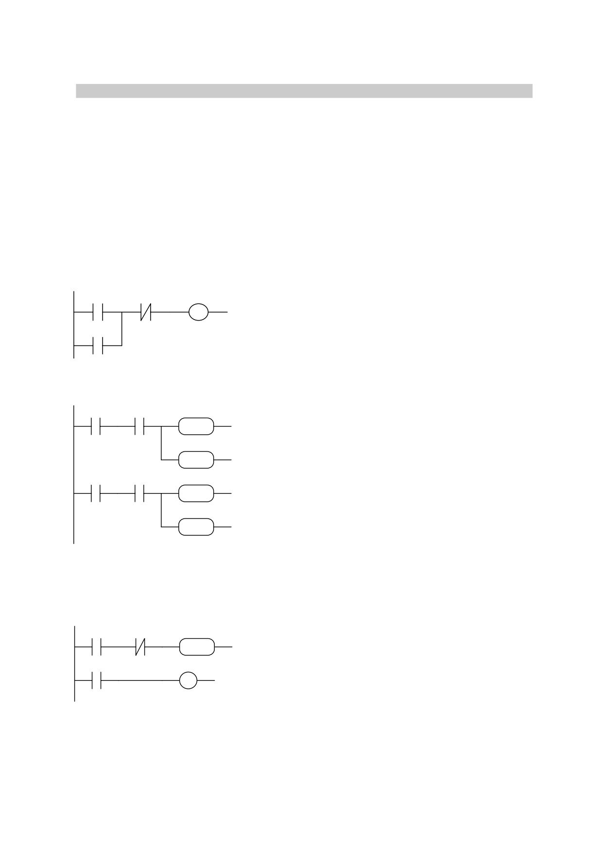
4.8.2. Examples and applications
The following examples illustrate possible functionalities obtained by suitable
programming of the HPD pico-PLC. The suggested solutions offer the possibility of reducing
the components required to build the machine or part of the machine while, in many cases,
also cutting the overall cost of the application. Note that the pico-PLC scanning time is 6.144
msec and the maximum number of instructions is 64; moreover, the PLC is designed
principally to manage the drive’s digital inputs and outputs.
In addition to a concise description of the application, the examples show the settings
required for HPD parameters and the pico-PLC program. The program is shown in ladder
diagrams and instruction listings.
Example 1: two inputs for on/off functions
90.1
90.2
91.2
LD
90.1
digital input 1 sets bit b91.2 to on
OR
91.2
digital input 2 sets bit b91.2 to off
91.2
ANDN 90.2
OUT
91.2
Example 2: changing a parameter value with the up/down keys
90.1
99.0
05 73 05
LD
09.1
digital input 1 in high status increases
ADD
AND
99.0
parameter Pr5 by one unit every 614
92 76 92
ADD
05.73.05
msec
ADD
92.76.92
ADD
90.2
99.0
05 71 05
LD
90.2
digital input 2 in high status decreases
ADD
AND
99.0
parameter Pr5 by one unit every 614
ADD
05.71.05
msec
92 76 92
ADD
92.76.92
ADD
Example 3: command on positive front of a digital input
90.1
90.10
70.8
LD
90.1
digital input 1 sets bit b70.8 just once
ANDN 90.10
when the signal changes from low to
SET
SET
70.8
high
90.1
90.10
LD
90.1
OUT
90.10
63
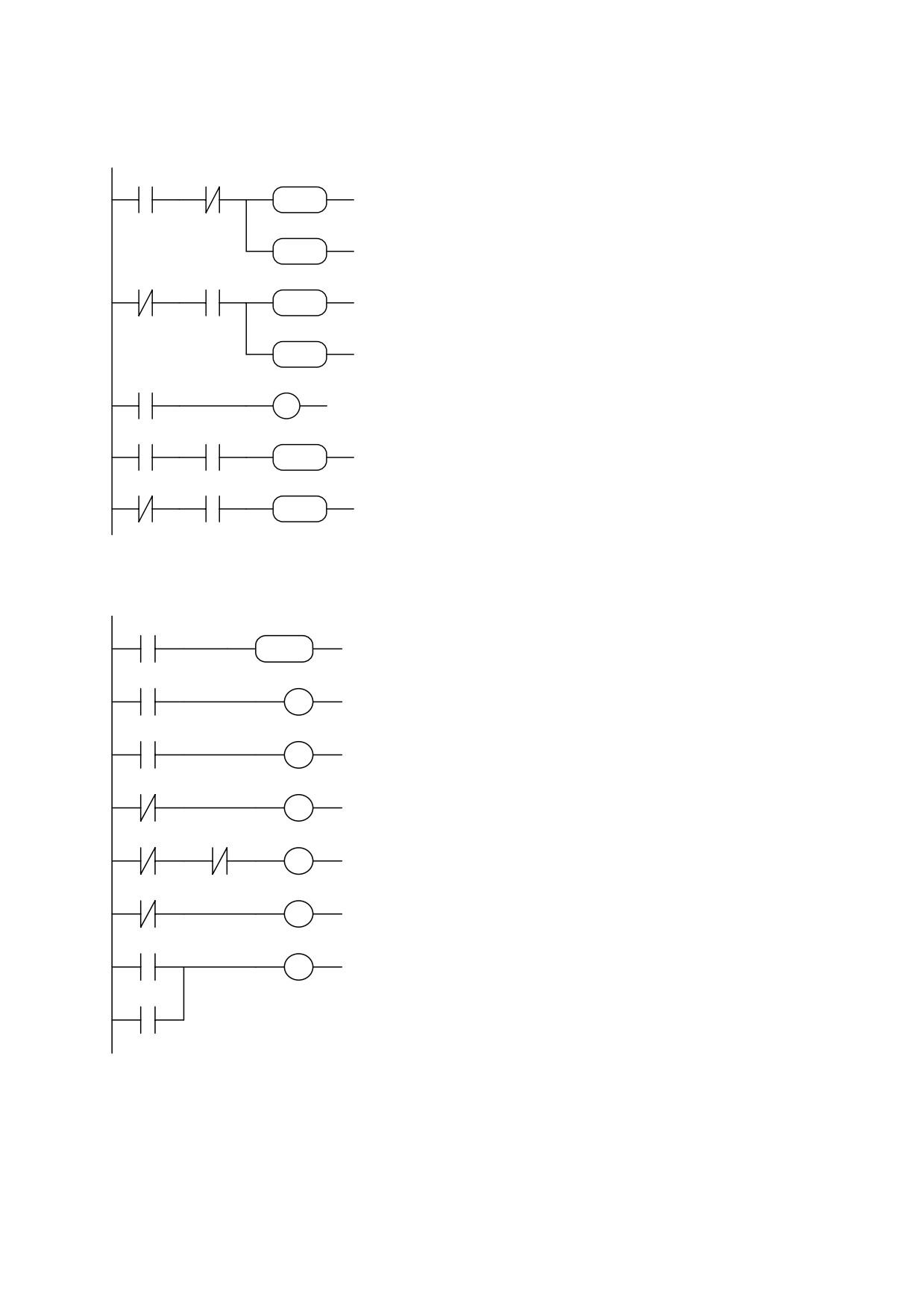
Example 4: filtered digital input at 60 msec
90.1
90.10
72 75 92
LD
90.1
if digital input 1 is low, load 60 msec
ANDN 90.10
on counter;
ADD
ADD
72,75,92
if digital input
1 is high for 60 msec
99.0
RST
99.0
b99.0 will be set to 1 and b90.11=1
RST
90.1
90.10
72 75 92
LDN
90.1
if digital input 1 is high, load 60 msec
ADD
AND
90.10
on counter
99.0
ADD
72,75,92
if digital input
1 is low for 60 msec,
RST
99.0
b99.0=1 and b90.11=0
RST
LD
90.1
90.1
90.10
OUT
90.10
LD
90.1
AND
99.0
90.1
99.0
90.11
SET
90.11
b90.11 is the status of filtered digital
SET
LDN
90.1
input 1
AND
99.0
90.1
99.0
90.11
RST
90.11
RST
Example 5: correlation between parameter values
99.13
00 80 72
LD
99.13
calculate difference between
Pr0
and
SUB
SUB
0,80,72
Pr80 to set b99.2 and b99.3
99.3
81.0
LD
99.3
OUT
81.0
if Pr0=Pr80 then b81.0=1
99.2
81.1
LD
99.2
OUT
81.1
if Pr0<Pr80 then b81.1=1
99.3
81.2
LDN
99.3
OUT
81.2
if Pr0<>Pr80 then b81.2=1
LDN
99.2
99.2
99.3
81.3
if Pr0>Pr80 then b81.3=1
ANDN
99.3
OUT
81.3
99.2
81.4
LDN
99.2
if Pr0>=Pr80 then b81.4=1
OUT
81.4
99.3
81.5
LD
99.3
if Pr0<=Pr80 then b81.5=1
OR
99.2
99.2
OUT
81.5
64
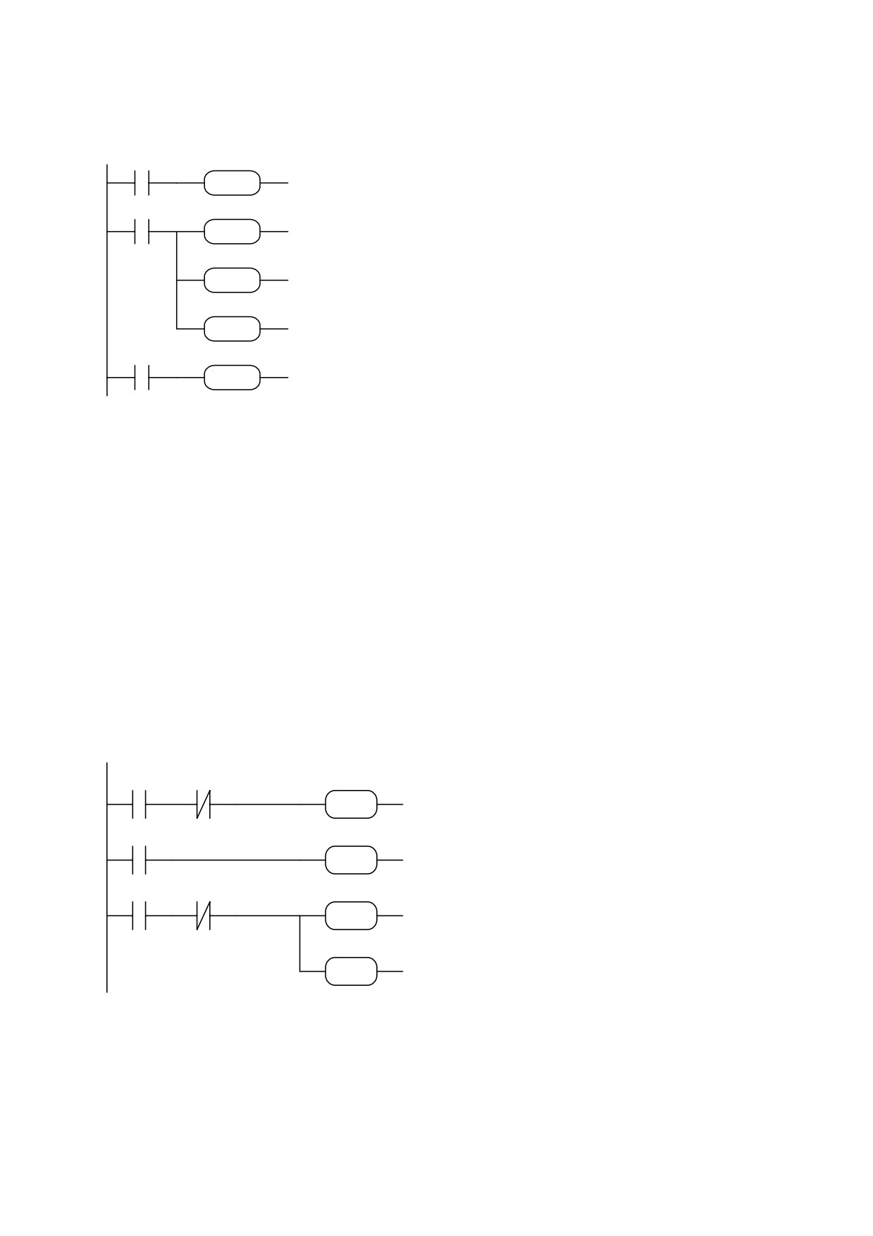
Example 6: filter (600 msec) for reading the value of a parameter
99.13
35 60 60
LD
99.13
Add Pr35 and Pr60
ADD
ADD
35,60,60
99.0
60 76 81
DIV
LD
99.0
if timer
1 expired calculate filtered Pr35
DIV
60,76,81
setting result in Pr81
60 60 60
SUB
SUB
60,60,60
zero set Pr60
92 76 92
ADD
92,76,92
reset time m 1 to 600 milliseconds
ADD
81.15
81 71 81
LD
81.15
if Pr81 is negative its sign changes
MUL
81,71,81
MUL
Example 7: homing
If you are using an operating mode with spatial control (9, 10 or 11) and you need to align
the motor with a zero position defined by a proximity sensor when the system is powered up.
You can use two digital inputs, one for the homing command and one to acquire the
proximity sensor signal. The commands are pulse type and the homing command is executed
once only.
After setting the default values set up the required operating mode (Pr31=xx, b99.11=1,
b40.2=1, and any other settings required) and then set the homing speed for the zero
proximity sensor in Pr5 and set b40.12=1 to enable Pr5 when b40.2 reaches zero.
Terminal 13 on X3 = pulse command - execute homing.
Terminal 14 on X3 = PNP axis zero proximity sensor.
Bit b91.10 is utilised to signal that the operation is terminated. Note that bits from b91.8 to
b91.15 are at the disposal of the PLC and cannot be stored in the memory.
The program is as follows:
90.2
91.10
40.2
LD
90.2
If
homing command not
ANDN
91.10
executed, disables operating
RST
RST
40.2
mode
91.10
40.2
LD
91.10
If homing command executed,
SET
SET
40.2
re-enables operating mode
90.3
91.10
70.10
LD
90.3
if proximity switch operated
SET
ANDN
91.10
resets operating mode counters
SET
70.10
sets homing executed flag
91.10
SET
91.10
SET
65
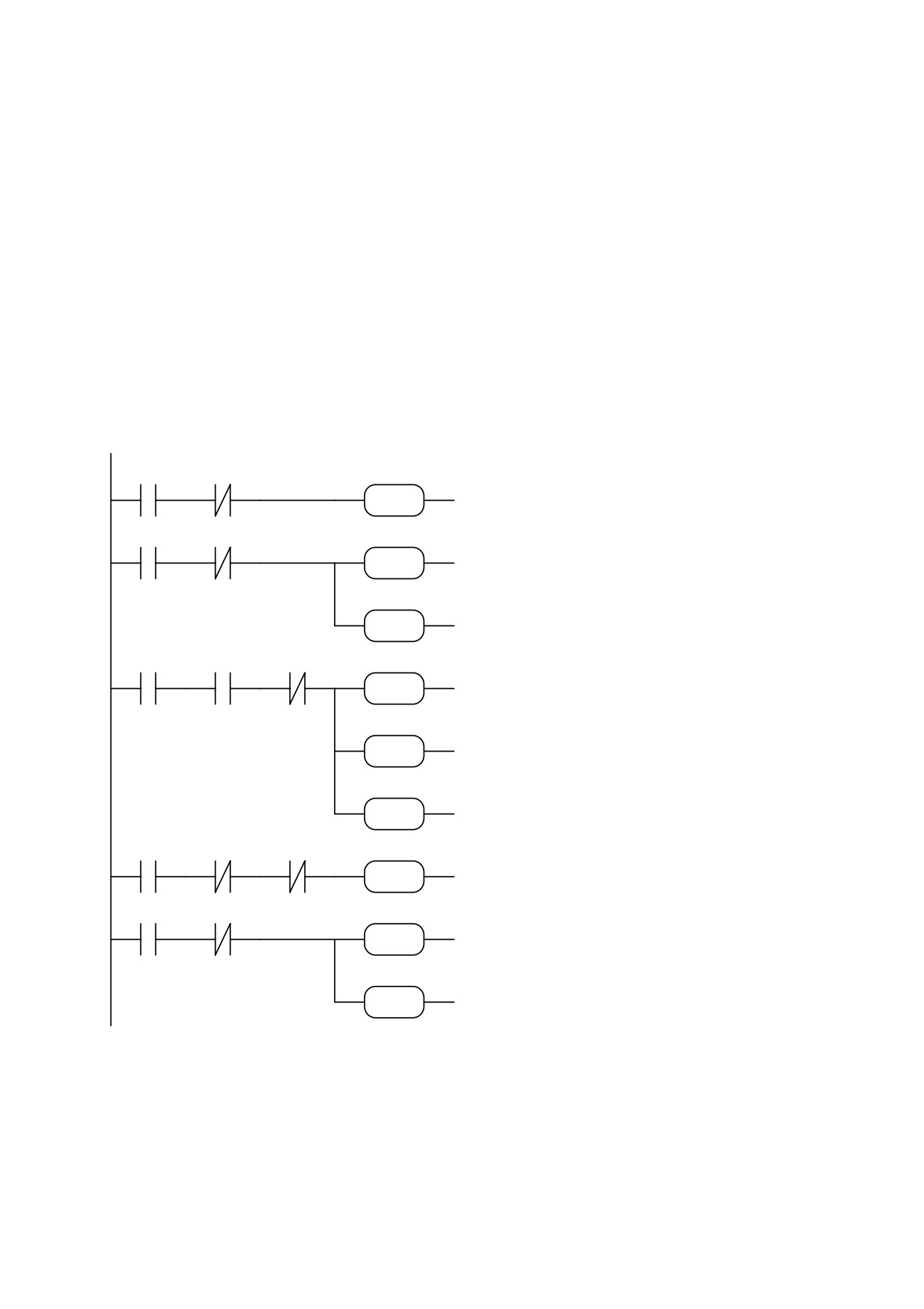
In certain cases a more precise axis zero reference is required; this is achieved using, in
addition to the proximity sensor on the machine, also the motor position transducer. In this
setup the proximity sensor signal is correlated with the first zero on the motor position
transducer.
The following example provides this functionality using operating mode (9) (trapezoidal
profile).
After setting default values, set up operating mode
9 (Pr31=9, b99.11=1, b40.2=0,
b40.12=1, and any other settings required) and then enter the zero proximity sensor homing
speed in Pr5.
Terminal 13 on X3 = homing pulse command.
Terminal 14 on X3 = PNP type axis zero proximity sensor.
Terminal 11 on X2 = digital output. Switches to 1 when the homing phase is terminated.
The following bits are utilised b91.8, b91.9, b91.11.
The program is as follows:
If homing command is given
90.2
91.9
40.2
LD
90.2
and not yet executed, disables
ANDN
91.9
RST
operating mode: the motor
RST
40.2
runs at speed set in Pr5
90.3
91.0
91.9
LD
90.3
when proximity
sensor
ANDN
91.0
SET
operates alignment is enabled
SET
91.9
on the resolver zero position
40.2
SET
40.2
SET
LD
91.9
91.9
41.2
91.8
79 28 64
proximity sensor trip is
AND
41.2
followed
by trapezoidal
SUB
ANDN
91.8
profile to align with resolver
SUB
79.28.64
70.8
zero position
SET
70.8
SET
91.8
SET
91.8
SET
LD
91.8
if alignment with resolver
ANDN
70.8
91.8
70.8
91.0
91.0
zero is terminated, sets axis
ANDN
91.0
zero terminated output
SET
SET
91.0
41.4
91.11
40.2
LD
41.4
if drive is OK operating mode
ANDN
91.11
SET
is enabled
SET
40.2
91.11
SET
91.11
SET
The precision of the positioning on the zero
resolver depends on the stability of the motor in the moment in which the trapezoidal profile
is calculated for final alignment. You must therefore make sure that the motor shaft has
stopped before this calculation. In the example above, the halted motor test is done with bit
b41.2. In this case, the imprecision is due to the fact that this bit has a precision of ±1 rpm.
Should greater precision be required, in place of the test b41.2 set a sufficient delay to ensure
that the motor shaft has stopped.
66
Example 8: execution of modulus in digital locking
(FILE: E001.HPD)
To obtain the following functionality: with reference to the figure assume you have a
conveyor transporting product and a blade roller driven by the HPD drive. At start up on an
external command the blade roller is aligned with a zero reference (proximity sensor). On
receipt of the next pulse command, which is generated by a product detection sensor, the
blade roller drive locks onto the conveyor master so that the product is always cut at precisely
the same length; when the cut is terminated the blade roller reassumes the starting position
awaiting the next cutting command.
In this case the program permits the homing procedure (see chapter 1) and then, on receipt
of the command from the product sensor, it assumes digital locked mode and covers a space
equal to the value of Pr87:86; when it reaches this distance the drive unlocks and ramps down
to the standby position defined by parameter Pr89:88 = modulus. Note that one motor shaft
revolution corresponds to 4096 steps so the modulus value to set is equal to the number of
steps required by the motor shaft to execute a full revolution of the blade roller. The value of
Pr87:86 must be less than the value of the modulus (=Pr89:88).
The master encoder mounted to the conveyor shaft provides the drive with a position
reference during the digital locking phase.
67

M
PROX SENSORBLADE
SLAVE MOTOR
SENSOR
E
MASTER ENCODER
When you have set the default values set the following parameters: Pr5=10 (homing
speed), Pr31=10, b99.11=1, b40.2=1, b40.12=1, Pr52=0, b70.3=1, Pr87:86=modulus - ramp,
Pr89:88=modulus in which the ramp is expressed in steps, i.e. it is the space that the axis must
cover during ramp down. Pay attention when programming Pr89:88 and Pr87:86 because
these parameters are utilised as double word format by the PLC but they must be set up as two
pairs of single whole words from the keypad. For example, if the modulus is 40960 steps,
Pr89 must be set to 0 and Pr88 must be set to 24576.
Terminal 13 on X3 = homing pulse command
Terminal 14 on X3 = NPN type axis zero proximity sensor
Terminal 12 on X3 = pulse command - digital locking engage sensor.
Terminal 12 on X2 = exit - high during modulus execution; if a digital lock command is
transmitted during execution of the modulus it will be ignored.
The delay before digital locking varies by up to 2.048 msec max.
The following auxiliary parameters are utilised: Pr83, Pr84, Pr85, b91.10, b91.12.
It is assumed that parameter Pr34 is not used.
The program is as follows:
68
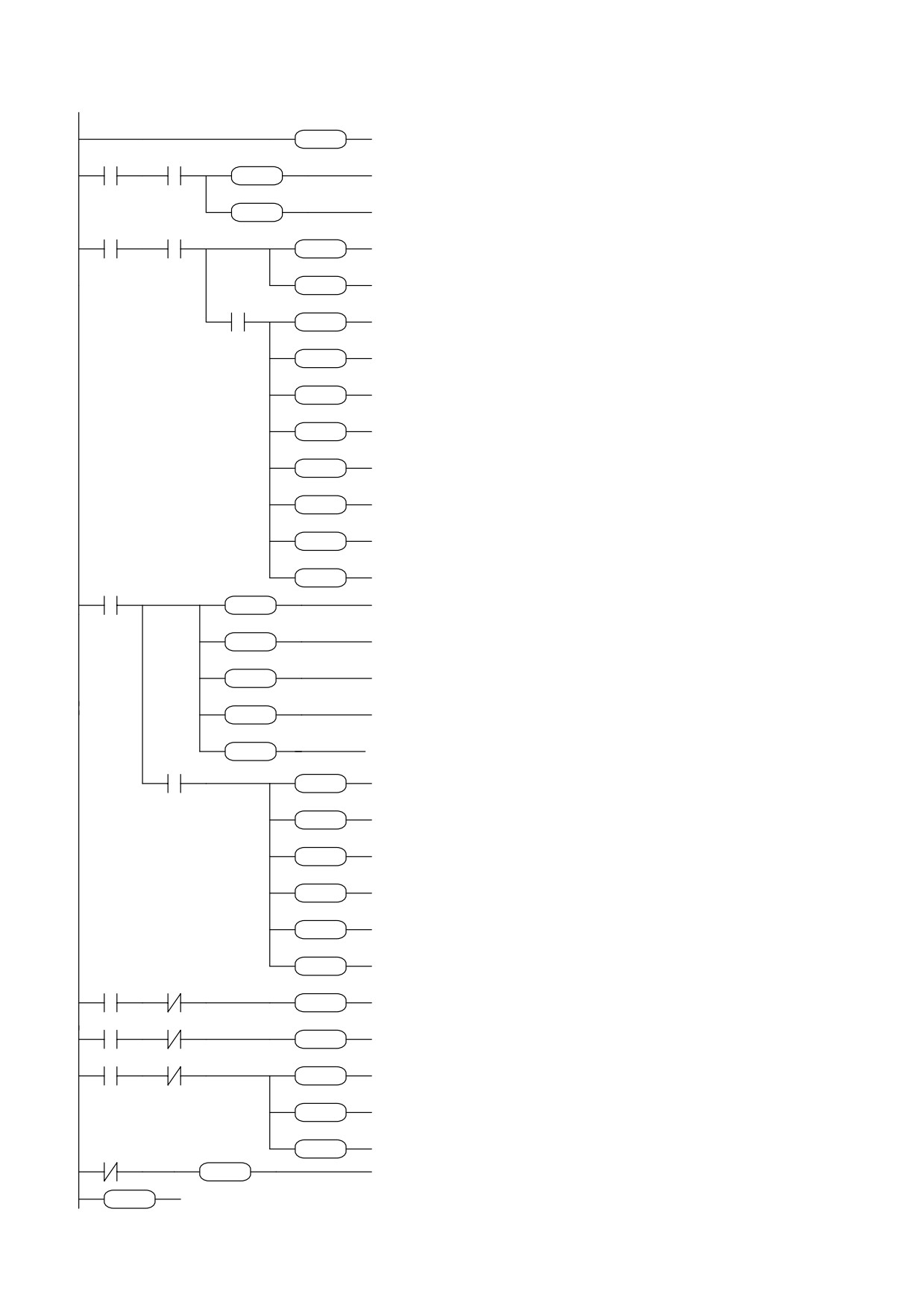
70.8
FIN
8.1
Fast input for digital lock trigger
FIN
90.1
70.8
94.5
LD
90.1
if the axis is locked
SET
AND
70.8
fast input disabled
91.1
SET
94.5
and output enabled (cycle in progress)
SET
SET
91.1
if homing has been carried out the bit is
91.10
70.8
94.0
LD
91.10
enabled.
SET
AND
70.8
86 62 84
SET
94.0
Force double word operation (comparison)
SUB
SUB
86.62.84
comparison for release test
85.15
55 72 05
AND
85.15
ADD
ADD
55.72.05
release test Pr86<Pr62
40.2
copy master speed into internal speed
RST
40.2
reference and enable it
RST
70.8
RST
70.8
release axis
RST
94.0
SET
94.0
force double word operation
SET
88 62 84
SUB
88.62.84
Pr84 = remaining space
SUB
94.0
SET
94.0
force double word operation
SET
84 55 83
DIV
84.55.83
Pr83 = time to reach zero rpm
DIV
91.12
SET
91.12
ramp stopped flag
SET
LD
91.12
91.12
94.0
SET
94.0
ramp down management?
SET
SUB
88.62.84
Force double word operation
88 62 84
Pr84 = remaining space
SUB
SET
94.0
94.0
force double word operation
SET
DIV
84.83.84
84 83 84
calculate ramp speed
ADD
72.84.05
DIV
and write in internal reference
72 84 05
AND
41.2
ADD
41.2
72 72 60
ADD
72.72.60
if speed is zero
SET
94.0
reset position reference (modulus close)
ADD
force double word operation
94.0
SUB
62.88.62
SET
subtract modulus from motor dimension
62 88 62
RST
91.12
SUB
deactivate ramp in progress flag
91.12
RST
91.1
RST
deactivate cycle in progress output
91.1
RST
94.5
RST
LD
91.10
enable fast output
94.5
ANDN
91.12
RST
SET
40.2
test if reference must be Pr6
91.10
91.12
40.2
LD
90.2
SET
ANDN
91.10
test whether to execute homing
RST
40.2
execute homing
90.2
91.10
40.2
LD
90.3
RST
ANDN
91.10
zero proximity sensor input
90.3
91.10
70.10
SET
70.10
honing end test…
SET
SET
91.10
position reset
91.10
RST
94.5
homing flag
SET
LDN
91.10
enable fast input
94.5
SET
94.5
if homing not executed
91.10
94.5
RST
END
disable fast input
SET
program end
END
69
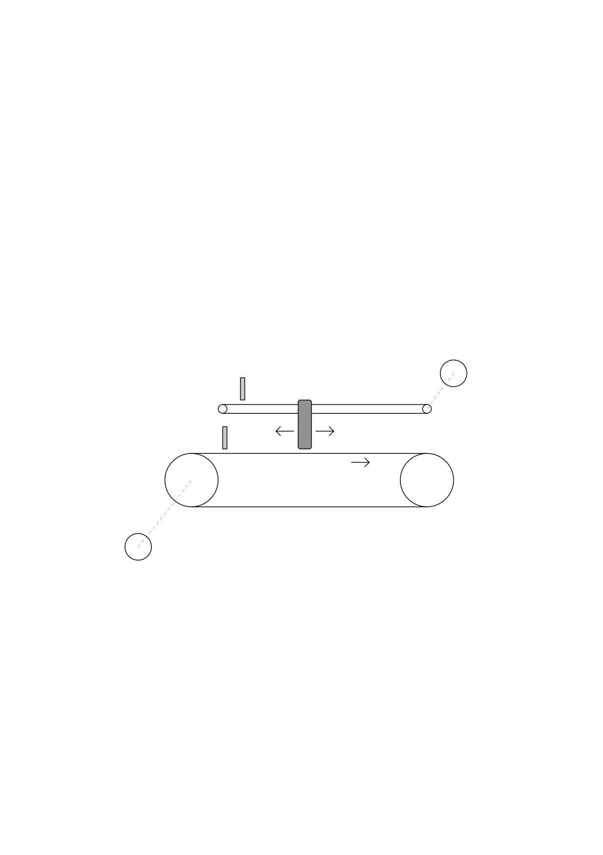
Example 9: movement with digital locking and return to origin
(FILE: E002.HPD)
To obtain the following functionality: with reference to the figure below assume there is a
conveyor transporting product and a carriage running parallel to the conveyor and controlled
by an HPD drive. On receipt of an external start command the carriage is aligned on a zero
reference position (proximity sensor). With a second pulse command, provided by a product
detection sensor, the drive locks on to the conveyor in order to perform an operation on the
product at a precisely defined position; when this operation is terminated the carriage returns
to its starting position.
In this case the program makes it possible to execute homing (see chapter 1) after which,
on receipt of the manual command from the sensor, the carriage locks on and covers a
distance equal to the value of Pr87:86; when this distance is reached the drive unlocks and
stops according to the ramp programmed in parameter Pr83. The motor now automatically
returns to the origin position executing a trapezoidal profile with the ramps set in Pr80 and the
speed in Pr81. Note that one motor revolution corresponds to 4096 steps so the value to set in
Pr87:86 should correspond to the number of steps of the motor shaft needed for the carriage to
execute the required translation.
The master encoder on the conveyor shaft provides the drive with the necessary position
reference during digital locking.
SLAVE MOTOR
PROX SENSOR
M
CARRIAGE
SENSOR
E
MASTER ENCODER
After having set the default values, program the following parameters:
Pr5=10 (homing speed), Pr31=10, b99.11=1, b40.2=1, b40.12=1, Pr80=trapezoidal profile
ramp, Pr81=trapezoidal profile speed, Pr82=copy of P.51 in digital locking, Pr83=digital
locking release deceleration ramp, Pr84=copy of Pr53 in digital locking, Pr87:86=release
dimension in steps
terminal 13 on X3 = pulse command for homing execution
terminal 14 on X3 = axis zero position PNP proximity sensor
terminal 12 on X3 = digital locking sensor pulse command
terminal 12 on X2 = output; high during cycle execution; digital locking commands received
during cycle execution will be disregarded.
The digital locking delay interval can be up to 6.144 msec.
The following auxiliary bits are utilised: b91.10, b91.12.
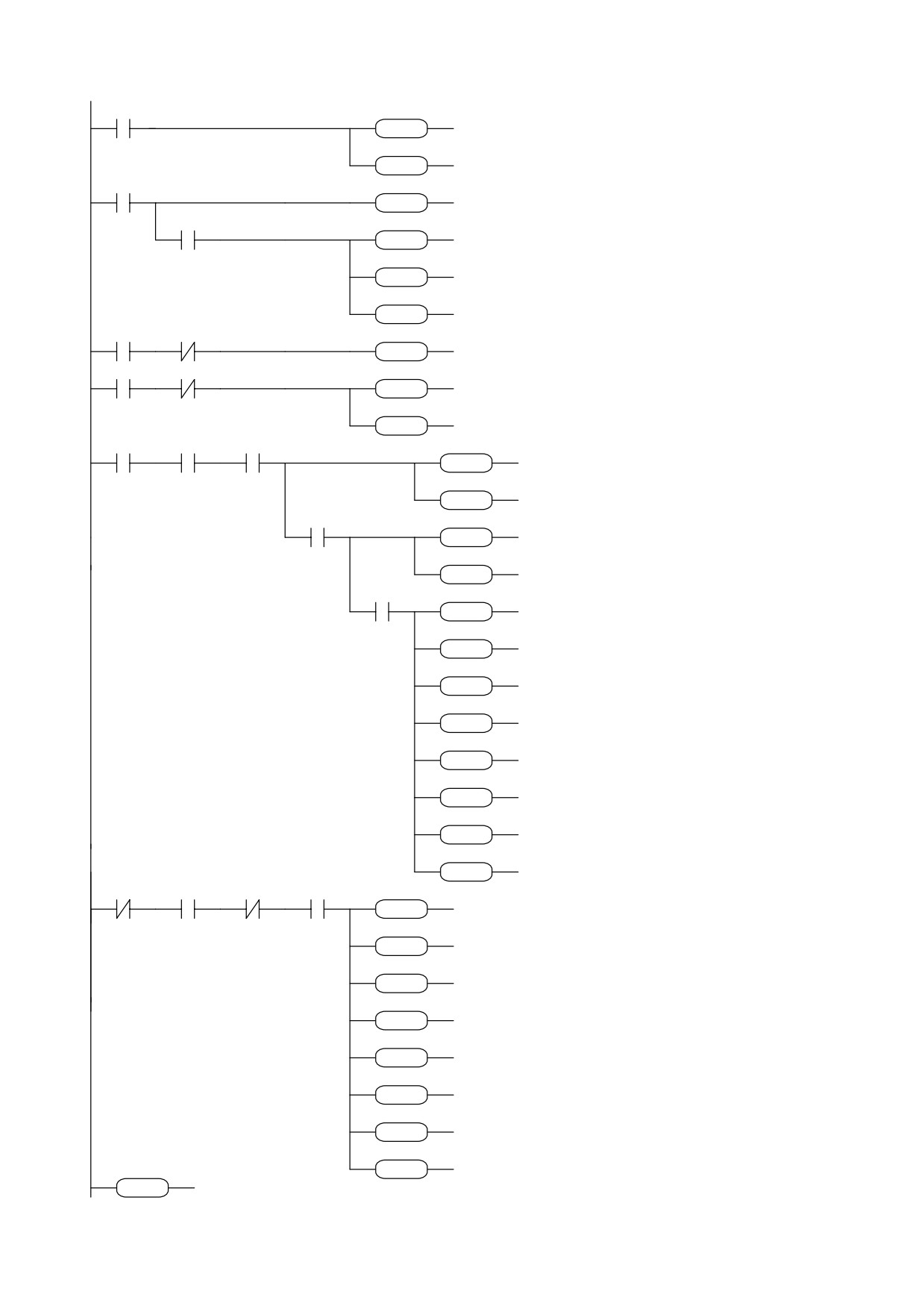
Program (see on next page) :
70
91.12
70.8
LD
91.12
return start management
SET
SET
70.8
with trapezoidal profile
91.12
RST
91.12
RST
LD
91.10
91.10
40.2
if homing exec. ref=pr6
SET
40.2
SET
90.1
70.8
locking start request
AND
90.1
SET
locking
SET
70.8
91.1
cycle output on
SET
91.1
SET
no ramp pr52=0
ADD
72.72.52
72 72 52
ADD
LD
90.2
homing request
90.2
91.10
40.2
ANDN
91.10
RST
40.2
RST
LD
90.3
90.3
91.10
70.10
stand by for proximity
ANDN
91.10
SET
reset dimensions
SET
70.10
91.10
homing exec. flag
SET
91.10
SET
LD
31.1
31.1
91.10
91.1
94.0
if OPM = 10
AND
91.10
SET
if homing is done
AND
91.1
86 60 88
and locked
SET
94.0
forces double word
SUB
SUB
86.60.88
release
dimension
89.15
72 83 52
AND
89.15
reached ?
ADD
ADD
72.83.52
set release ramp
RST
70.8
70.8
and release axis
AND
41.2
RST
if speed is zero
SUB
31.31.31
41.2
31 31 31
disable OPM
ADD
72.72.70
SUB
reset all b70
72 72 70
ADD
72.80.51
ADD
trapezoidal profile ramp
72 80 51
ADD
72.81.52
trapezoidal profile speed
ADD
72 81 52
ADD
72.60.64
copy
position
in
ADD
incremental dimension
72 60 64
SET
70.4
and reverse for return
ADD
set OPM 9
ADD
71.75.31
70.4
SET
preset start
71 75 31
profile at next scan
SET
91.12
ADD
91.12
if no profile in exec.
LDN
70.8
SET
Motor stopped
AND
41.2
no profile preset
70.8
41.2
91.12
31.0
31 31 31
ANDN
91.12
and OPM is 9
SUB
AND
31.0
disable OPM
72 82 51
SUB
31.31.31
reset ratio
ADD
ADD
72.82.51
reset ratio
ADD
72.84.53
72 84 53
zero set slip
ADD
72.72.58
ADD
zero set all bits
ADD
72.72.70
72 72 58
ADD
SET
70.6
72 72 70
enable feed forward
ADD
ADD
72.75.31
70.6
set OPM 10
SET
RST
91.1
zero set current cycle
72 75 31
ADD
END
program end
91.1
RST
END
71
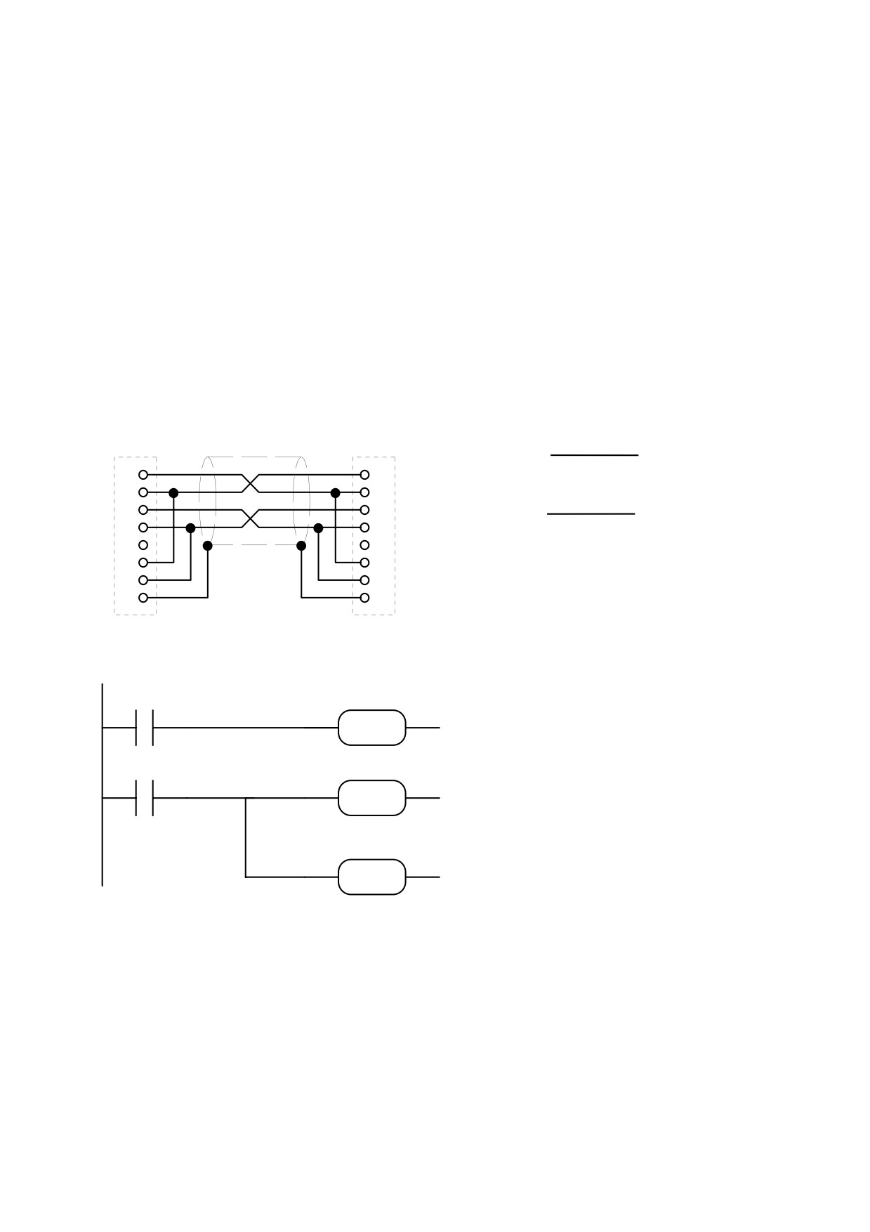
Example 10: Inter-Drive Communication
IDC (Inter Drive Communication) refers to a specific configuration of the serial port of the
HPD drive that makes it possible to interchange parameters between two or more units.
With IDC enabled (Pr26=10) if bit b99.5 is set to 1 the HPD activates a broadcast
command by sending the value of Pr81 to the address of Pr80. HPDs that receive broadcast
commands with Pr26=10 automatically set b99.5 to 1 causing automatic transmission of Pr81
to the address of Pr80 in broadcast mode. Using this potential, it is extremely simple to
connect two HPD drives in a loop via the serial ports, and a short program on the internal
PLC will suffice to start transmission at power-on and restore it in the event of
communication errors. The following example describes the PLC program required to copy
Pr81 from the two drives in parameters Pr80.
Connection
function
drive 1
drive 2
drive 1
drive 2
X5
X5
1
1
2
2
Pr81
Pr80
3
3
4
4
5
5
Pr80
Pr81
6
6
7
7
8
8
99.5
75 74 92
LD
99.5
If broadcast is received
DIV
timer is set to 30ms
DIV
75.74.92
99.0
99.5
if time-out is present
LD
99.0
SET
SET
99.5
reset serial comms
75 74 92
DIV
75.74.92
and set timer
DIV
These PLC instructions must be entered on only one of the drives; both drives must have
parameter Pr26=10 to enable the IDC function.
72
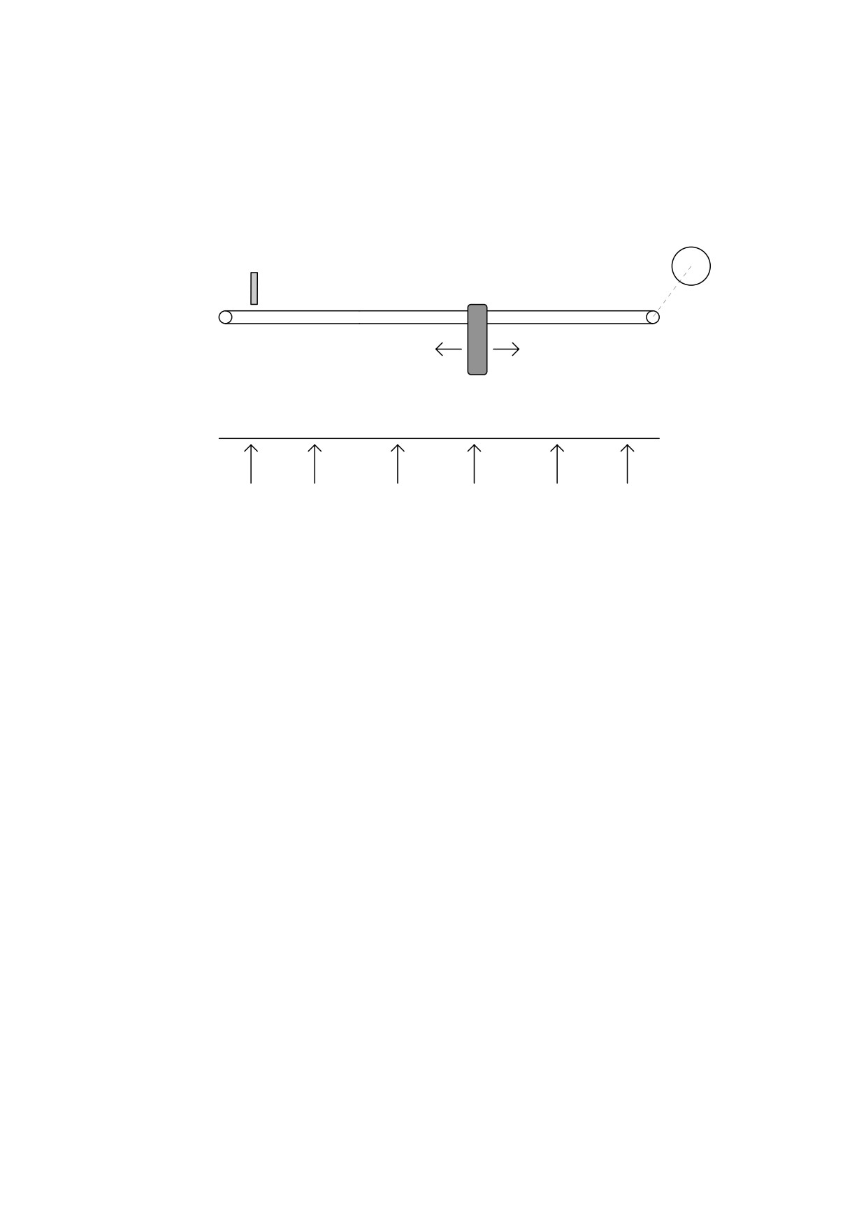
Example 11: 5 positioning with teach-in
(FILE: E003.HPD)
To obtain the following functionality: with reference to the figure, assume you need to
acquire 5 different machine positions and then execute them automatically.
MOTOR
PROX SENSOR
M
CARRIAGE
POSITIONS: 0
1
2
3
4
5
This can be achieved using a smart keypad module (see appendix L, SBC1 program)
connected on the serial communications line with the drive and with the internal PLC. When
the machine is powered up the drive will stand by to receive the homing exec command and
the keypad will show the message “axis zero (F4)”. By pressing [F4] or sending a pulse
command to digital input 2 of the drive, the motor shaft will turn at the speed established by
parameter Pr5 until the intervention of the proximity sensor at digital input 3. The keypad
display will now present the message “automatic dimension 1”; digital inputs 4, 5 and 6 select
the position to be reached, while a pulse supplied to digital input 1 provides a trapezoidal
profile to reach the selected position. The following table shows the relationship between
parameters Pr80...Pr89 and the encoding of the 3 digital inputs; for example, input 4 on one
selects position 1 and the distance in steps between the zero axis point and position 1 is set in
Pr81:80, bearing in mind that one revolution of the motor shaft is equivalent to 4096 steps.
73

Input 6
Input 5
Input 4
position
dimension
0
0
1
1
Pr81:80
0
1
0
2
Pr83:82
0
1
1
3
Pr85:84
1
0
0
4
Pr87:86
1
0
1
5
Pr89:88
other combinations
0
axis zero
If you want to set the dimension from the keypad, press [F3] and the display will show the
message “dimension xx
yyyy“ where xx defines the dimension in question and yyyy
determines the relative value. The [+] and [-] keys are used to modify the value yyyy while
[F3] changes the value xx.
If you wish to acquire the required position by moving the carriage, press [F1]: the display
will show the message “manual dimension xx “; [F1] selects the xx dimension to be
programmed while [+] and [-] are used to move the carriage. The [+] key provides the motor
start/stop in the positive direction, while [-] provides the start/stop in a negative direction; the
translation speed in this case must be set in parameter Pr4. Once the required position has
been reached, press [C] to confirm the dimension. Press [F2] to set automatic mode.
To store the parameters you have programmed press [S].
After having set the default values, set the following parameters on the HPD drive:
Pr4=10 manual translation speed
Pr5=5 homing speed
Pr31=9, b99.11=1, b40.2=1, b40.12=1
Pr81:80=dimension 1
Pr83:82=dimension 2
Pr85:84=dimension 3
Pr87:86=dimension 4
Pr89:88=dimension 5
terminal 12 on X3 = pulse command - execute positioning
terminal 13 on X3 = pulse command - execute homing
terminal 14 on X3 = PNP zero axis proximity sensor
terminal 15 on X3 = select position
terminal 16 on X3 = select position
terminal 17 on X3 = select position
terminal 11 on X2 = output: high during homing
terminal 12 on X2 = output, high during positioning
terminal 13 on X2 = output, high during manual translation
The following auxiliary bits are utilised: b91.10, b91.11.
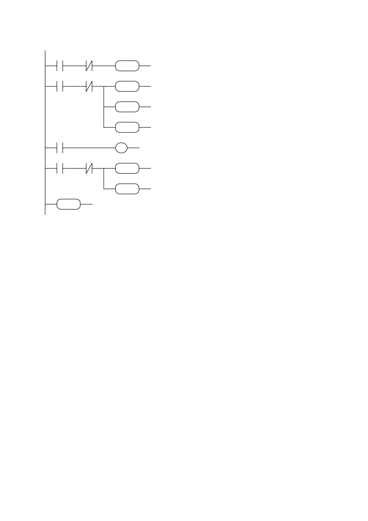
The program is as follows:
74
90.2
91.10
40.2
LD
90.2
If digital input 2 and homing not
RST
ANDN 91.10
yet executed, executes homing
RST
40.2
90.3
91.10
70.10
SET
LD
90.3
If digital input 3 and homing not
91.10
ANDN 91.10
yet executed
SET
SET
70.10
reset mode counters
91.0
SET
91.10
set homing executed flag
RST
91.0
set digital output 0 to zero
RST
70.8
91.1
LD
70.8
copy bit b70.8 to digital output 1
OUT
91.1
41.4
91.11
40.2
LD
41.4
if drive OK, enable operating mode
SET
ANDN 91.11
at power up
91.11
SET
40.2
SET
91.11
SET
END
program end
END
Inputs and outputs can be read and written directly via
the serial communications line so there is no need to use the pico-PLC if you have an
intelligent unit connected to the drive via the serial line. For more information regarding the
serial line, refer to the HPD user manual.
75
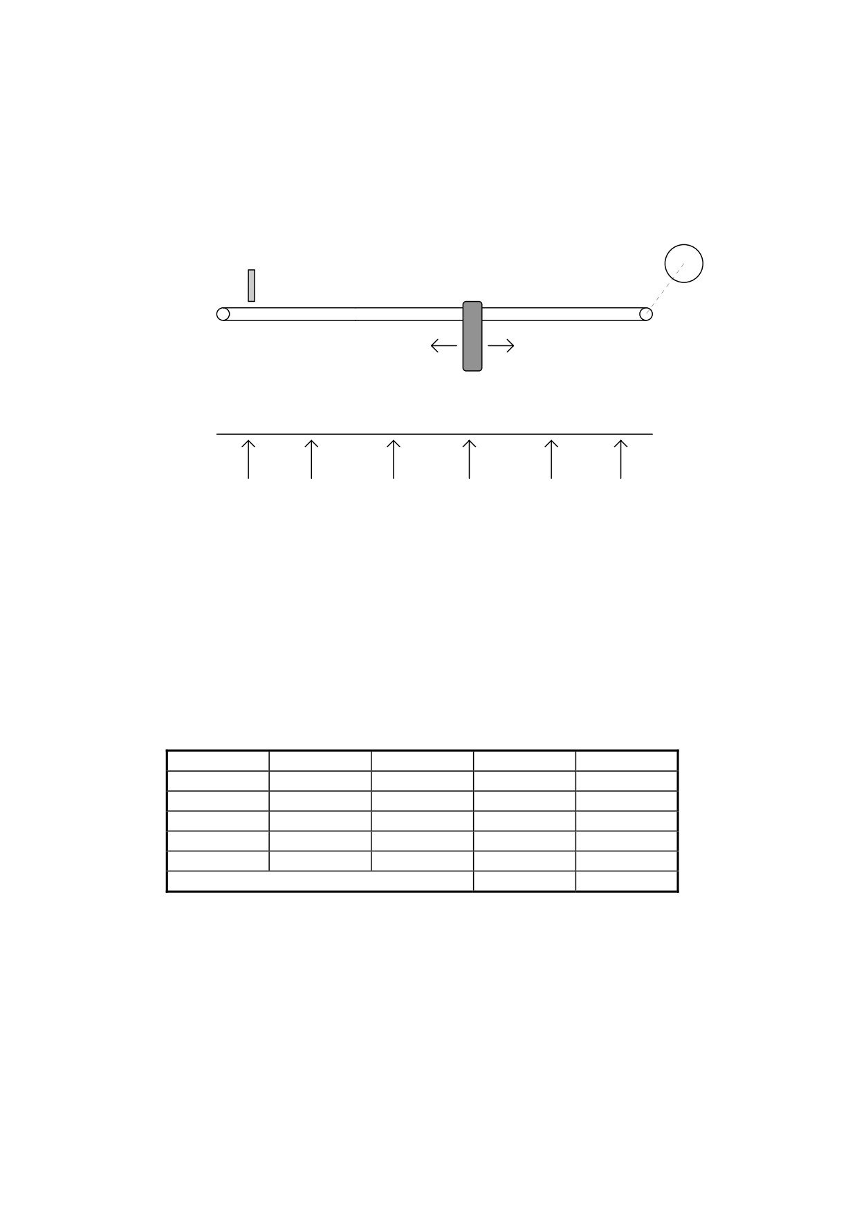
Example 12: 5 positioning
(FILE: E004.HPD)
Referring to the figure below, assume you need to move the carriage to 5 different
positions selected by means of three digital signals.
MOTOR
PROXIMITY SENSOR
M
CARRIAGE
POSITIONS: 0
1
2
3
4
5
The positions are set in parameters Pr80...Pr89 in resolver steps taking the position of the
proximity sensor as the zero value. When the machine is powered up the drive remains in
standby mode awaiting the homing execution command: when a pulse command is supplied
to digital input 2 of the HPD drive the motor shaft will turn at the speed set in parameter Pr5
until the proximity switch provides a signal at digital input 3. At this point digital inputs 4, 5
and 6 select the position to be reached, while a pulse on digital input 1 makes it possible to
perform positioning on a trapezoidal profile. The following table shows the relationship
between parameters Pr80...Pr89 and the encoding on the 3 digital inputs; for example, only
input 4 on one selects position 1 and the distance in steps between the zero axis point and
position 1 is set in steps, bearing in mind that one revolution of the motor shaft corresponds to
4096 steps.
Input 6
Input 5
Input 4
Position
Dimension
0
0
1
1
Pr81:80
0
1
0
2
Pr83:82
0
1
1
3
Pr85:84
1
0
0
4
Pr87:86
1
0
1
5
Pr89:88
other combinations
0
axis zero
After having set the default values, set the following parameters on the HPD unit:
Pr5=5 homing speed
Pr31=9, b99.11=1, b40.2=1, b40.12=1
Pr81:80= dimension 1
Pr83:82= dimension 2
Pr85:84= dimension 3
Pr87:86= dimension 4
Pr89:88= dimension 5
76
terminal 12 on X3 = execute positioning - pulse command
terminal 13 on X3 = execute homing - pulse command
terminal 14 on X3 = PNP axis zero proximity sensor
terminal 15 on X3 = position selection
terminal 16 on X3 = position selection
terminal 17 on X3 = position selection
terminal 12 on X2 = output, high during positioning
The following auxiliary bits are utilised: b91.10, b91.11.
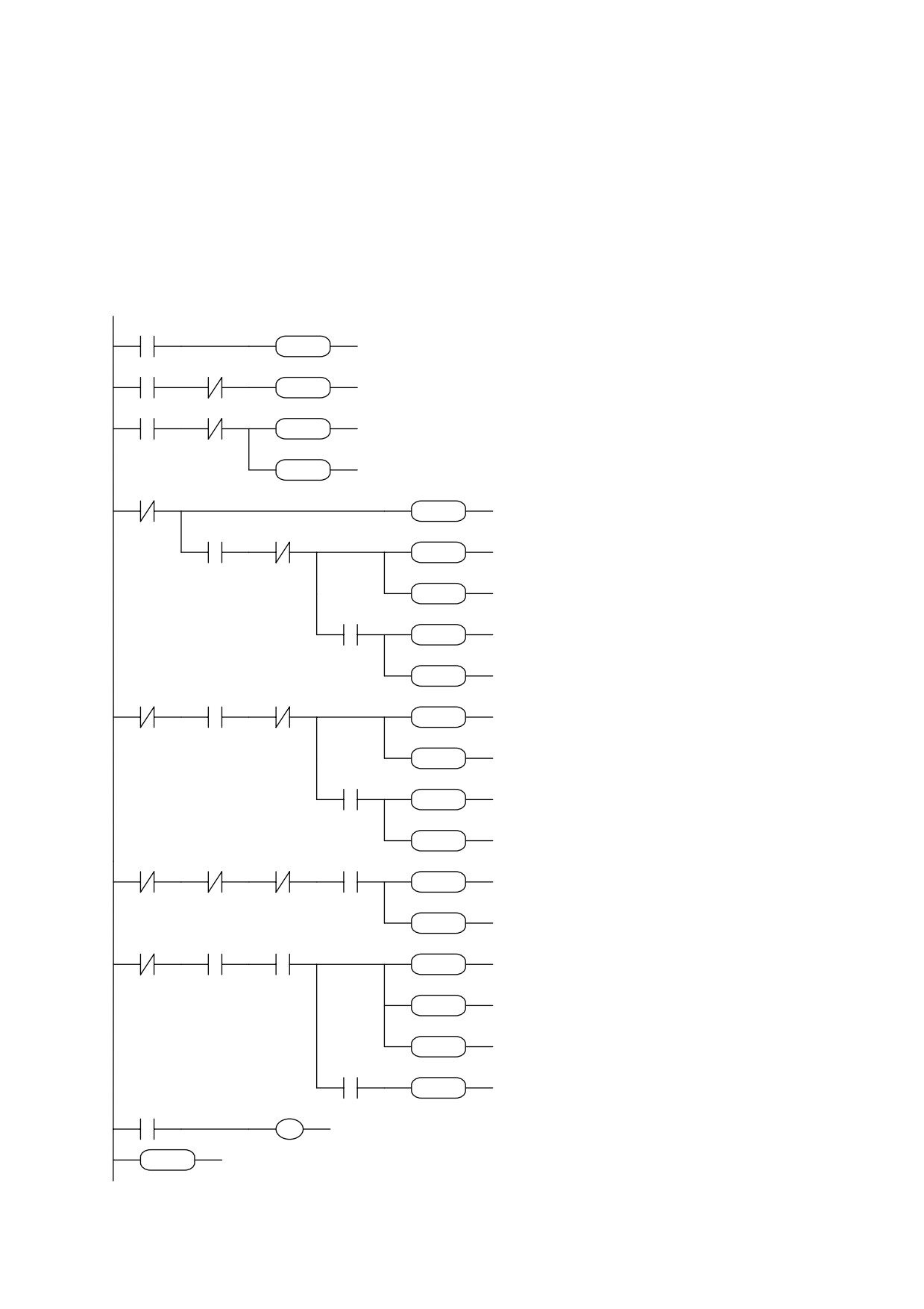
Program:
91.10
40.2
LD
91.10
If
homing already
SET
40.2
executed
enable
SET
operating mode
90.2
91.10
40.2
LD
90.2
RST
ANDN
91.10
If digital input
2
90.3
91.10
70.10
SET
40.2
execute homing if not
SET
LD
90.3
yet done
ANDN
91.10
91.10
SET
70.10
if digital input
3 and
SET
SET
91.10
homing not executed:
70.8
72 72 64
reset counters
ADD
LDN
70.8
homing exec flag
90.4
90.5
94.0
ADD
72.72.64
digital output 0 at zero
AND
90.4
SET
ANDN
90.5
if profile terminated,
80 72 64
SET
94.0
select
dimension
ADD
ADD
80.72.64
according to the three
90.6
94.0
AND
90.6
digital inputs
SET
94.0
SET
ADD
88.72.64
88 72 64
LDN
70.8
ADD
AND
90.5
70.8
90.5
90.6
94.0
ANDN
90.6
SET
SET
94.0
ADD
82.72.64
82 72 64
AND
90.4
ADD
SET
94.0
90.4
94.0
ADD
84.72.64
SET
LDN
70.8
84 72 64
ANDN
90.4
ANDN
90.5
ADD
AND
90.6
70.8
90.4
90.5
90.6
94.0
SET
94.0
SET
ADD
86.72.64
86 72 64
ADD
LDN
70.8
if profile terminated
AND
91.10
and input 1=1 execute
70.8
91.10
90.1
70.8
AND
90.1
profile
resetting
SET
SET
70.8
direction
bit
and
70.4
RST
70.4
calculating
distance
RST
SUB
64.60.64
with respect to current
AND
99.2
motor position
64 60 64
SET
70.4
if negative sign set
SUB
b70.4=1
99.2
70.4
LD
70.8
SET
OUT
91.1
digital
output
2
70.8
91.1
END
indicates profile on
program end
END
77
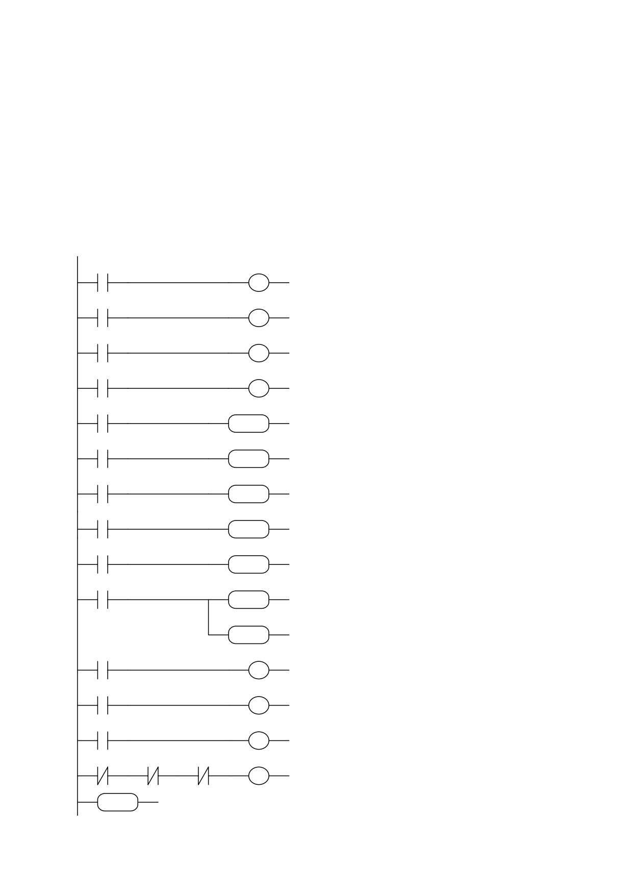
Example 13: reading 4-digit controller
(FILE: E005.HPD)
You wish to change the value of parameter Pr83 using a 4-digit controller. Four digital inputs and four
digital outputs are used for this:
block 12 of X2 = output to select the first digit (least significant) of the controller
block 13 of X2 = output to select the second digit of the controller
block 14 of X2 = output to select the third digit of the controller
block 15 of X2 = output to select the fourth digit of the controller
blocks 12...15 of X3 = inputs to read digits in BCD (block 12 is the least significant bit; the connection
diagram is shown on the following page).
LD
90.1
Copy bit 0 digit BCD
90.1
80.0
OUT
80.0
LD
90.2
copy bit 1 digit BCD
90.2
80.1
OUT
80.1
LD
90.3
copy bit 2 digit BCD
90.3
80.2
OUT
80.2
copy bit 3 digit BCD
LD
90.4
90.4
80.3
OUT
80.3
if first digit
calculate units
LD
91.1
91.1
80 73 81
MUL
80.73.81
if second digit
MUL
calculate tens places
LD
91.2
91.2
80 75 81
MUL
80.75.81
if third digit
MUL
calculate hundreds
LD
91.3
91.3
80 76 81
MUL
80.76.81
if fourth digit
MUL
calculate thousands
LD
91.4
91.4
80 77 81
MUL
80.77.81
sum the digitd calculated in
the
MUL
auxiliary parameter Pr81
LD
99.13
99.13
81 82 82
ADD
81.82.82
if last digit (most significant)
ADD
copy the final value in Pr83
LD
91.4
91.4
82 72 83
ADD
82.72.83
set parameter Pr82 to zero
ADD
SUB
82.82.82
updates the outputs so as to enable
82 82 82
the reading of the next digit
LD
91.3
SUB
OUT
91.4
91.3
91.4
LD
91.2
OUT
91.3
91.2
91.3
LD
91.1
OUT
91.2
if the last digit has already been
91.1
91.2
LDN
91.2
read, restart the scan of the digits
ANDN
91.3
starting from the units
ANDN
91.4
91.2
913
91.4
91.1
OUT
91.1
END
end of program
END
78