Parker HPD N (HPD2N, HPD5N, HPD8N, HPD16N, HPD20N,HPD24N). User’s manual (2004) - page 2
In addition to the parameter values and the pico-PLC instructions, the display may show the
following messages:
r. xx At the time of power-up this message indicates the software version installed (2
seconds approx.).
IdLE At power-up and in correspondence with Pr0 this message shows that no alarms are
present and the system is disabled.
run
At the time of power-up and in correspondence with Pr0 this message indicates that
no alarms are present and the drive is enabled; the motor shaft may be spinning.
Er. xx In correspondence with Pr0 this message indicates that the drive has detected an
alarm (xx indicates the alarm code) and has therefore been disabled. When an alarm
is detected the display automatically switches to parameter Pr0 and shows the alarm
code.
dcbuS In correspondence with Pr0 this message indicates that the drive is not operating at
low voltage (b40.10=0) and that DC bus voltage is still below the 120 V threshold;
the inrush current circuit is still connected so the drive is not yet ready (b41.4=0).
Prxx Indication of parameter xx (value displayed by pressing “M”).
Pb. xx Indication of bit parameter xx.
bxx.yy Indication of bit yy of parameter xx; press “M” to display bit status.
In. xx Indication of instruction xx of PLC program.
donE Displayed for approximately 1 second each time a command is entered.
rESet Displayed for approximately 1 second each time an alarm reset command is entered
(b99.10).
tESt
Displayed during wiring test (b70.3).
rEtrY
It’s displayed when a writing error is detected storing the pico-PLC instructions
(b99.14) or while saving parameters (b99.15).
4.2. Commissioning the HPD drive
The steps described in this section must be followed carefully when the drive is started up
for the first time.
1) Connect the motor to the drive in compliance with the wiring diagrams in the manual.
2) Make sure the drive is disabled (terminal 11 of board X3 must be open)
3) Power up the drive.
4) After some seconds the display shows “IdLE”.
5) Setting essential parameters:
Pr33 calculation (rated current)
InM
Pr33 =
⋅
100
InD ⋅2
27
where:
InM is rated motor current at zero rpm in Ampere
InD is rated drive current in Ampere
The maximum value of Pr33 is 50.0 except for HPD20N because the
limit is 31.
Pr19 calculation (peak current)
Pr19
= Pr33⋅3
MAX
The maximum value must be no higher than three times the value of Pr33
Pr29 calculation (number of poles)
Use the following table for MB series motors
Flange ( mm )
Pr29
56
4
70
4
105
8
145
8
205
8
Pr32 calculation (rated speed)
If Pb 42.6=0
Pr32 = Vmax ⋅ 1.12
ω⋅V
MAIN
If Pb 42.6=1
Pr32 =
⋅
8.3
VMOT
where: ω is nominal motor speed in rad/sec
Vmain is HPD power supply in Vrms
Vmot is motor rated voltage in Vrms
Evaluation of Pr16 and Pr17 (speed regulator gain)
The default values of Pr16 and Pr17 have been chosen considering identical motor and
drive rated currents; if this is not the case correct the values of parameters Pr16 and Pr17
with the ratio of the motor rated current/drive rated current. Preventive execution of this
compensation will eliminate the risk of motor vibration at the first start-up.
6)
Set the analogue reference signal to 0 V (terminals 1, 2 of board X2), and enable the drive
(24 V on terminal 11 of board X3 ).
7)
The motor shaft must be stopped; when the analogue reference voltage is changed motor
speed should change proportionally. If this is not the case check your wiring.
8)
Save your changes with b99.15.
28
The drive is preset with default values designed to meet the requirements of the majority of
applications. With the default values the pico-PLC in the drive runs the program described in
appendix G, so the following functions will be present on the input and output terminal
boards:
TERMINAL BOARD X2
TERMINAL BOARD X3
11
real speed > Pr13
11
start drive
12
motor speed = reference (+/- 20 rpm)
12
left-hand stroke end (n. c.)
13
real speed = 0
13
right-hand stroke end (n. c.)
14
real speed > 0
14
emergency stop (n. c.)
15
motor thermal image active (i2t)
15
clockwise/counter-clockwise rotation
16
16
start / stop
17
terminal A
drive ready
17
18
terminal B
(n.c. contact)
18
The functions on terminals 12, 13 and 14 must be enabled by setting bit b90.10 to one.
This requires access to the extended parameters menu.
The default PLC program controls parameter Pr5 in addition to timer 1 (Pr92) and bits
b40.0, b40.4, b40.5, b40.6, b40.12 so in this case the above binary parameters and switches
cannot be utilised unless the pico-PLC is disabled
(b99.13=0) or the basic program is
modified.
Short and extended menu
When the HPD drive is in default status, only a limited number of parameters are
displayed. These parameters are the only ones required for applications in which the HPD is
employed as a straightforward frequency converter, i.e. you are not using the advanced
functions of the drive (e.g. using HPD with a Numerical Control or an intelligent axis control
card). Switch between short and extended menu using b99.6.
Short memory parameters are:
Pr0
Real speed of motor shaft in rpm.
Pr1
Analogue reference offset (terminals 1 and 2 of terminal board X2 ).
Pr2
Analogue reference full scale: speed value in rpm corresponding to 10 V reference
signal.
Pr8
Acceleration/deceleration ramp values in seconds per 1000 rpm
Pr16
Integral gain of speed control loop.
Pr17
Speed control loop damping.
Pr19
Peak current delivered to drive expressed as a percentage of the peak rated value of
the drive.
Pr29
Number of motor poles.
Pr32
Rated speed (rpm).
29
Pr33
Rated current that can be delivered by the drive (can be maintained indefinitely)
expressed in percent of the peak rated current of the drive.
Pr35
Instantaneous current requested by the motor expressed as a percentage of drive peak
rated current.
b99
Bit parameter for the fundamental orders.
Using extended menu you can manage all parameters and pico-PLC instructions.
Restoring default parameters
If you need to restore the factory-set default parameter values:
- disable the drive via hardware (open terminal 11 on board X3)
- power-up the system
- the display will show “IdLE” after approximately 3 seconds
- set b99.7 and b99.13 to zero
- enter command b99.12
- save your changes with b99.14 and b99.15.
4.3. Basic parameters
To access all the following parameters open the extended menu by setting b99.6 to one.
For this procedure, b99.7 must be set to zero.
DECIMAL PARAMETERS
Pr0
Motor speed: this is a read-only parameter expressed in rpm; the message Pr0 never
appears on the display. In its place a message corresponding to drive status is shown.
Pr1
Analogue reference offset. This is expressed in input A/D converter counts.
Programming limits are -10000 and +10000 while the range of the A/D converter is
from -16384 to +16383 over ± 10 V.
Pr2
First full scale of analogue reference. Unit=rpm, range=±10000, default=3000. If
b40.0=0 and b40.12=0, Pr7 will be equal to: Vin ⋅ Pr2 / 9.76 where Vin is the
voltage on the analogue input.
Pr3
Second full scale of analogue reference. Unit=rpm, range=±10000, default=-3000.
If b40.0=1 and b40.12=0, Pr7 will be equal to: Vin ⋅ Pr3 / 9.76 where Vin is the
voltage on the analogue input.
Pr4
Frequency reference full scale
(connector X6). Unit=rpm, range=±32767,
default=3000. If b40.12=1 and b40.13=1, Pr7 will have the following value:
if b42.5=0
Pr7 = Fin ⋅ Pr4 / 2000000
(frequency/direction signal)
if b42.5=1
Pr7 = Fin ⋅ Pr4 / 500000
(quadrature signal)
where Fin is the frequency on the encoder input.
30
Pr5
Internal reference. Unit=rpm, range=±9000, default=0. If b40.12=1 and b40.13=0,
Pr7 will be the same as Pr5.
Pr6
Reserved read-only speed reference. Unit=rpm, range=±9000. If b40.2=1 Pr6 is
only utilised as a speed reference for the control loop. The active operating mode will
enter its speed request in parameter Pr6.
Pr7
Main reference (read-only parameter). Unit=rpm, range=±9000. If b40.2=0, Pr7 is
used as a reference for the speed control loop. In certain operating modes Pr7 can be
used as a reference for other factors (torque / acceleration). In this case Pr7 is
expressed in a suitable unit.
Pr8
Acceleration ramp for positive speed values. Unit=s/krpm range=0.002..65.535,
resolution=0.001 s, default=0.002 s. Acceleration for positive speeds required of the
motor by way of the speed reference is internally limited so that acceleration of 1000
rpm takes Pr8 seconds.
Pr9
Deceleration ramp for positive speed values. Unit=s/krpm, range=0.002..65.535,
resolution=0.001 s, default=0.002 s. Deceleration for positive speeds required of the
motor by way of the speed reference is internally limited so that deceleration of 1000
rpm takes Pr9 seconds.
Pr10
Acceleration ramp for negative speed values. Unit=s/krpm, range=0.002..65.535,
resolution=0.001 s, default=0.002 s. Acceleration for negative speeds required of the
motor by way of the speed reference is internally limited so that acceleration of 1000
rpm takes Pr10 seconds.
Pr11
Deceleration ramp for negative speed values. Unit=s/krpm, range=0.002..65.535,
resolution=0.001 s, default=0.002 s. Deceleration for negative speeds required of the
motor by way of the speed reference is internally limited so that deceleration of 1000
rpm takes Pr11 seconds.
Pr12
Deceleration ramp for stroke end and stop functions. Unit=s/krpm,
range=0.002..65.535, resolution=0.001 s, default=0.002 s. Deceleration required of
the motor by the stroke limit and stop functions is internally limited so deceleration
of 1000 rpm takes Pr12 seconds.
Pr13
Overspeed threshold. Unit=rpm, range=0..+13000, default=3500. If the absolute
value for motor speed exceeds the value entered in Pr13, b41.0 must be =1, otherwise
it will be = 0.
Pr14
High speed threshold. Unit=rpm, range=±13000, default=20. When b40.7=0, if the
speed difference between motor and reference is less than Pr14 and greater than
Pr15, b41.1 will be =1, otherwise it will be = 0. In the case of b40.7=1, if motor
speed is less than Pr14 and higher than Pr15, b41.1 will be =1, otherwise it will be
=0.
Pr15
Low speed threshold. Unit=rpm, range= ±13000, default=20. When b40.7=0, if the
speed difference between motor and reference is less than Pr14 and greater than
Pr15, b41.1 will be =1, otherwise it will be =0. In the case of b40.7=1, if motor speed
is less than Pr14 and higher than Pr15, b41.1 will be =1, otherwise it will be =0.
Pr16
Integral gain of speed control loop. Range =0...32767, default=120.
Pr17
Speed control loop damping. Range=0...32767, default=2000. If Pr16 is set to zero
Pr17 sets the value for proportional gain of the speed control loop.
Pr18
Bandwidth limiter. Unit=512µs, range=0..1000, default=1. Use Pr18 to set the time
constant of a first order filter located on the digital torque demand signal. The filter
cut-off frequency will be: 310/Pr18 Hertz.
31

Pr19
Peak current. Unit=%, range=0..100.0%, resolution=0.1%, default=100.0%.
Maximum current that the drive can deliver to the motor expressed as a percentage of
drive peak current. It is good practice to maintain this value to within 3 times the
rated motor current.
Pr20
DC bus voltage. Unit=volt, read-only parameter. Shows the value of DC bus
voltage.
Pr21
Torque limiter, read-only parameter. Unit=%. Can be used by operating modes to
restrict motor torque.
Pr22
Auxiliary analogue reference. Unit=%. The displayed value will be
Pr22=Vin⋅100/9.76. Resolution is 0.2%.
Pr23
Alarm code. This code shows the currently active alarm; zero means that no alarms
are active. Consult the table of alarm codes for more details.
Pr24
Last alarm. This parameter stores the last alarm. Pr24 is reset when the alarm reset
command is entered (b99.10).
Alarm code
Alarm
0
no alarm
1
overvoltage
2
undervoltage
3
overcurrent
4
resolver alarm
5
motor overheating
6
drive overheating
7
external alarm
8
auxiliary alarm
9
digital output overcurrent alarm
10
PLC check-sum
11
parameter check-sum
Pr25
Code describing installed software version. Read-only parameter.
Pr26
Serial line baud-rate code. Default=8. This is the code for programming
transmission speed. For more information consult the section on the serial interface.
Pr27
Serial line address code. Default=0, possible settings=0..31. For more information
consult the relative section of the manual.
Pr28
Motor shaft position. Unit=steps, range=0..4095. Read-only parameter that shows
the absolute position of the resolver.
Pr29
Number of motor poles. Possible settings=2..64, default=8.
Pr30
Resolver position offset. Default=0; use Pr30 for electronic correction of the
mechanical resolver position.
Pr31
Operating mode. Default=0. Use Pr31 to select the active operating mode. 0
indicates no operating mode.
Pr32
Rated speed. Unit=rpm, range=0..9000, default=3200. Nominal motor speed.
Should be programmed with the motor speed at which rated voltage corresponds to
drive power feeding voltage reduced by
13%. Consult the formula in section
Commissioning the HPD drive.
32
Pr33 Motor rated current. Unit=% of peak current, range=10.0..50.0%, resolution=0.1%
default=50.0%. Enter motor rated current.
Pr34 Tacho generator emulation output gain. Default=127. Use parameter 34 to alter
analogue output gain in proportion to speed (terminal 9 on board X2). The analog
output value (Volt) is:
Pr 0
⋅
Pr 34
tacho
=
K
⋅ 15875
where: K = 1 if Pr32 ≤ 875
K = 4 if 875 < Pr32 ≤ 3500
K = 16 if Pr32 > 3500
Pr35 Torque monitor. Unit=% of peak torque, resolution 0.1%. This parameter indicates
the percentage of torque (or current) that the motor is delivering.
Pr36 Thermal image of motor winding. Unit=% of reference temperature. This read-
only parameter indicates an estimation of the heat on the innermost windings of the
motor. If the value reaches 100.0 %, which is equal to the nominal value, b41.11
switches to 1 so that current can be limited to the rated value.
Pr37 Thermal image of braking resistor. Unit=% of nominal temperature. This read-
only parameter indicates an estimation of the heat on the braking resistor. If the value
reaches 100.0 % or more, consider using an external braking resistor.
Pr38 Auxiliary analogue output. Unit=% of
9.76V, default=0, range=±100.0%,
resolution 8 bit. If b40.11 is equal to 1, the auxiliary analogue output will be equal to
976⋅Pr38/100 volts.
Pr39 Phase correction. This parameter may be used in certain applications with special
motors that are to run also at constant power. Range ±32000, default = 0.
33
BINARY PARAMETERS
Binary parameter Pb40 can be read, written and saved. Binary parameter Pb41 provides
information regarding system status. Parameters Pb42 and Pb99 are read/write parameters
with save facility.
b40.0
Selecting the first or second speed reference full scale value. Default=0. If set to 0
Pr2 is used to standardise the analogue reference. If set to 1 parameter Pr3 is used.
b40.1
Activation of algorithm for the suppression of vibration at 0 rpm. Default=0. Set
to 1 to activate the algorithm.
b40.2
Selecting user/reserved reference. If set to 1 the reserved reference is used in
accordance with the currently active operating mode. If set to zero the reference
selected by b40.0, b40.12 and b40.13. is employed. Default is 0.
b40.3
Reference freeze. Default=0. If set to 1 the reference will not be updated so that
motor will not follow input reference modifications. If set to zero the reference will
follow variation in the input reference.
b40.4
Left-hand stroke end. Default=0. If set to 1 and the selected reference requires
negative speed, the reference will be forced to zero in accordance with the ramp in
Pr12. If set to zero no type of control is performed.
b40.5
Right-hand stroke end. Default=0. If set to 1 and the selected reference requires
positive speed, the reference will be forced to zero in accordance with the ramp set in
Pr12. If set to zero no control Is performed.
b40.6
Stop function. Default=0. If set to 1 the motor is stopped according to the ramp set
in Pr12.
b40.7
Absolute/relative speed window selection. Default=0. If set to zero speed windows
Pr14 Pr15 b41.1 will operate in relative mode, if set to 1 the speed windows will
operate in absolute mode.
b40.8
Analogue torque limit. Default=0. If set to 1, Pr22, i.e. auxiliary analogue input,
will be used to limit motor torque.
b40.9
Software enable. Default=1. If set to zero the drive cannot be started.
b40.10
Low voltage operation enable. Default=0. If at 1 the inrush current circuit will be
connected each time the drive is disabled, thus permitting rapid increases in power
supply voltage. When the drive is started the inrush current circuit will be connected
before the effective start-up of the power stage. This procedure causes a drive start-
up delay of 120ms.
b40.11
Analogue output selector. Default=0. If set to 0 the analogue output will carry a
signal proportional to motor torque. If set to 1 it carries a value proportional to Pr38.
b40.12
Digital/analogue reference selector. Default=0. If set to 0 the analogue input is
selected as the main reference. If set to 1 the reference will be digital and, by means
of 40.13, it can be set for internal or external. If set for an external input, using b42.5
this can be set for quadrature or frequency/direction.
b40.13
Internal or frequency reference selector. Default=0. If b40.12=1, b40.13 can be set
to 0 to select internal reference, or to 1 to select the frequency input (encoder-in)
which, in turn can be configured as frequency/direction or quadrature signal using
b42.5.
34
b40.14
Serial communication enable. Default=0. Set this parameter to 1 to enable serial
comms.
b40.15
Reserved. Must remain on zero.
b41.0
Overspeed. When the absolute motor speed value exceeds the value set in Pr13,
b41.0 is on 1, otherwise it is on 0.
b41.1
At speed. With b40.7=0 if the speed difference between motor and reference is lower
than Pr14 and higher than Pr15, b41.1 will be 1, otherwise it will be 0. With b40.7=1,
if motor speed is lower than Pr14 and higher than Pr15, b41.1 will be 1, otherwise it
will be 0.
b41.2
Zero speed. If motor speed (Pr0) is zero rpm, b41.2=1, otherwise b41.2=0.
b41.3
Forward. If motor speed (Pr0) is positive b41.3=1, otherwise b41.3=0.
b41.4
Drive Healthy. If =1 no alarms are present, otherwise =0.
b41.5
Hardware enable status. 1 when hardware enable is set.
b41.6
Temperature pre-alarm. 10 degrees before reaching the maximum temperature of
the power stage, b41.6 is set to 1.
b41.7
External alarm. Alarm for user’s equipment.
b41.8
Auxiliary alarm. Second alarm for user’s equipment.
b41.9
Calibration failed. b41.9=1 indicates that initial calibration of current offsets has
terminated incorrectly.
b41.10
Speed control saturation. b41.10=1 when the speed control loop is delivering
maximum current.
b41.11
I2T active. Indicates that Pr36 has reached 100.0 % and therefore the drive is
restricting current to the rated value.
b41.12
Drive enabled.
b41.13
Keypad fault. b41.12=1 if communication between keypad and drive has failed.
b41.14
External operating mode. If set to 1 an external operating mode is installed.
b41.15
External operating mode time slot. If set to 1 indicates that the external operating
mode is controlled at 2 ms intervals otherwise at 512µs.
b42.0
Selector to configure encoder emulation.
b42.1
Selector to configure encoder emulation.
b42.2
Selector to configure encoder emulation.
Pr32 up to 9000 rpm
================
Pr32 up to 3500 rpm
==========================
Pr32 up to
875 rpm
=====================================
ENCODER OUT
16384
8192
4096
2048
1024
512
256
128
b42.0
0
1
0
1
0
1
0
1
b42.1
0
0
1
1
0
0
1
1
b42.2
0
0
0
0
1
1
1
1
the double line indicates encoder resolutions available in the various speed ranges
Default value is 1024
b42.4
24V over current. Digital output trip.
b42.5
Frequency input (board X6). If set to 1 the frequency input is programmed to
receive two phases in quadrature. This is the default. If set to 0 it is enabled to
receive a frequency/direction type input.
35
b42.6 Torque compensation. Default=1. When set to
1 torque compensation is
implemented to improve linearity of response.
b42.7 Reserved.
b99.6 Extended menu enable. Default=0. Set to 1 to enable the extended menu.
b99.7 Security. Default=0. Set to 1 to prevent parameter modification.
B99.8 Automatic reset undervoltage. Default
=0. if used the backup function, the
parameter must be 1, and in this case the undervoltage alarm is automatically reset.
b99.13 pico-PLC status. Default=1. If on 1 the PLC program is run, if on zero the program
is not run and the PLC instructions can be modified if required.
4.4. Basic commands
To transmit the following commands b99.7 must be on zero. For commands b42.3 and
b94.1, b99.6 must be on one.
b42.3
Re-initialise serial line. Command to reinitialise the serial line when the
communication speed (Pr26) has been modified. In any event, the serial line is
initialised when the drive is started up.
b94.1
Reset main reference offset. This command automatically sets parameter Pr1 in
order to reset any voltage offset on the main analogue reference. This procedure is
only possible if the absolute offset value is less than 200 mV.
b99.9
Current offset calibration request. The command is accepted only if the drive is
disabled. The calibration procedure is executed when the drive is started up.
b99.10
Alarm reset. This command resets Pr23 and Pr24; if the alarm persists it is shown
on the display. The command is not accepted in the presence of checksum errors
(Pr23=10, 11); in this case set default parameters (b99.12) and then reset the alarm.
If the backup power supply is present (terminals 8 and 9 on X3), when mains power
is restored to the terminals on X4 you must wait 10 seconds before transmitting the
undervoltage alarm reset command and enabling the drive.
b99.11
Operating mode parameter default values. This command sets current operating
parameters to default values. The command is executed only if b40.2 = 0.
b99.12
Default values. This command sets all parameters to default values and cancels the
values used by the operating modes; it also sets the pico-PLC program as described
in appendix G. If a checksum alarm is present, Pr23 and Pr24 are set to zero so that
the alarm can be reset. The command is executed only if b99.13 = 0.
b99.14
Save pico-PLC instructions. Saves the pico-PLC program. If an error occurs while
saving, “retry” is shown on display: in this case transmit the command again.
b99.15
Save parameters. Stores all parameters. This command is not possible in the
presence of a checksum error; in this case, set default parameters, reset the alarm and
then save the new parameterisation settings. If an error occurs while saving, “retry”
is shown on display: in this case transmit the command again.
36
4.5. Calibrating speed loop
IMPORTANT CONCEPTS
SPEED LOOP: the main task of any drive is to control motor speed so that it follows, as
faithfully as possible, the required speed, which is generally referred to as the REFERENCE.
High fidelity reproduction of the reference implies that motor speed is identical to reference
speed in static conditions and also that it follows speed requirements closely also in the case
of sudden changes in the speed reference (dynamic conditions). To perform this task the drive
must be informed of various characteristics of the motor and the mechanical system to which
the motor is coupled; this type of information is set in the CALIBRATION PARAMETERS.
ERROR: the error refers to the difference between reference speed and motor speed. The
error value is utilised by the speed control loop to calculate (using calibration parameters)
how much current to supply to the motor.
TORQUE: current flowing through the motor windings is converted into torque which
allows the motor to accelerate and decelerate.
GAIN: in consideration of the typical applications of the HPD drive, the expression “gain”
in this section of the manual refers to “stiffness”. To understand the concept of stiffness
imagine a motor controlled by a drive with speed demand of zero rpm. The motor shaft will
appear immobile but if we apply torque to the shaft it will rotate through an angle that
depends on the amount of torque applied. We can then apply the rated torque of the motor and
then measure the “stiffness angle” in degrees. The resulting value provides an indication of
the fidelity of the drive thus parametrised, although it is clearly not the only fidelity indicator.
WHAT’S NEEDED
To calibrate an HPD drive correctly we recommend using an oscilloscope with memory.
Obviously, the technician in charge must be well versed in the use of the instrument. If it is
impossible to use an oscilloscope, we illustrate, at the end of this section of the manual, an
alternative although less accurate method.
37
BEFORE STARTING
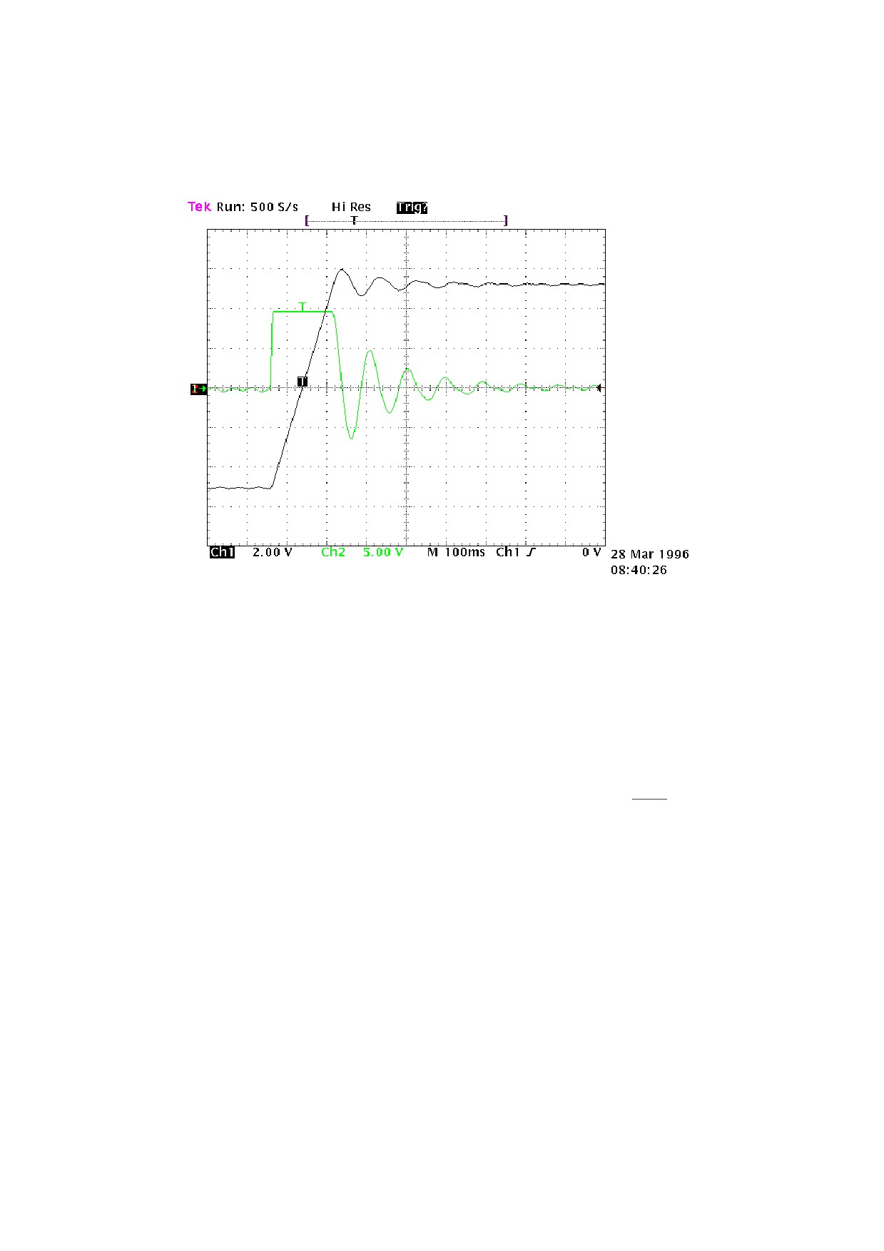
Before starting observe figure 1.
Fig. 1
The graph shows system response to a square wave speed reference. Channel 1 (Ch1) is
speed and channel 2 (Ch2) is motor current. The channel 1 oscilloscope probe is connected to
terminal 9 of X2 and channel 2 to terminal 7 of X2. The V/div scale and the timebase are not
mentioned as they may vary considerably.
CALCULATING Pr16
The value of Pr16 should be calculated before enabling the drive. Pr16 defines system
Pr 33
gain. To convert Pr16 into degrees for rated torque use the formula:
ac =
⋅ 28 where ac is
Pr16
the stiffness angle. Obviously, before the formula can be used Pr33 must be set to motor rated
current. To evaluate ac correctly we shall consider that, if the driven machine transmission is
rigid (not flexible) and there is no transmission backlash, the optimal stiffness angle could be
around 4 degrees. If the transmission is not sufficiently rigid it may be necessary to reduce
gain. If motor torque has been selected to achieve steep acceleration ramps, while dynamic
torque changes in normal operation are minimal, stiffness angles of 20, 30 or 40 degrees are
acceptable without negatively affecting performance. If you encounter difficulty in choosing
the most appropriate stiffness angle, start from 10 degrees, which is the default value when
using a motor with the same rated current as the drive.
Now enter the calculated value for Pr16 and start the motor with a square wave reference
signal (pay attention when setting the reference amplitude and frequency to avoid problems in
the case of limited stroke axes). On the oscilloscope note that the response changes as Pr17 is
altered. Lowering Pr17 will allow you to approach system response as shown in figure 2.
38
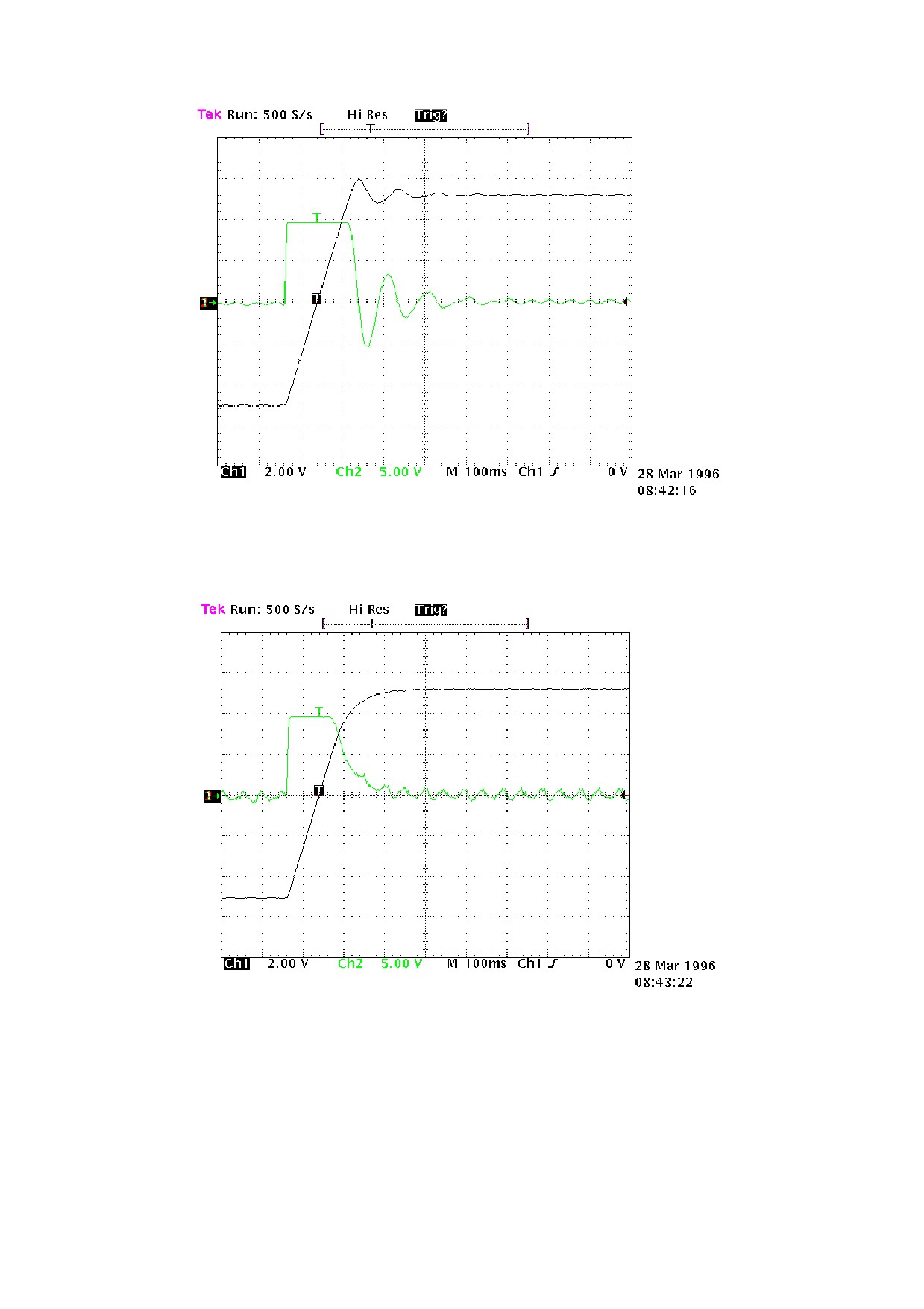
Fig.2
For higher values of Pr17 system response will resemble the situation of figure 3 below.
Fig.3
The optimal value of Pr17 can be considered when system response is as shown in figure 4.
39
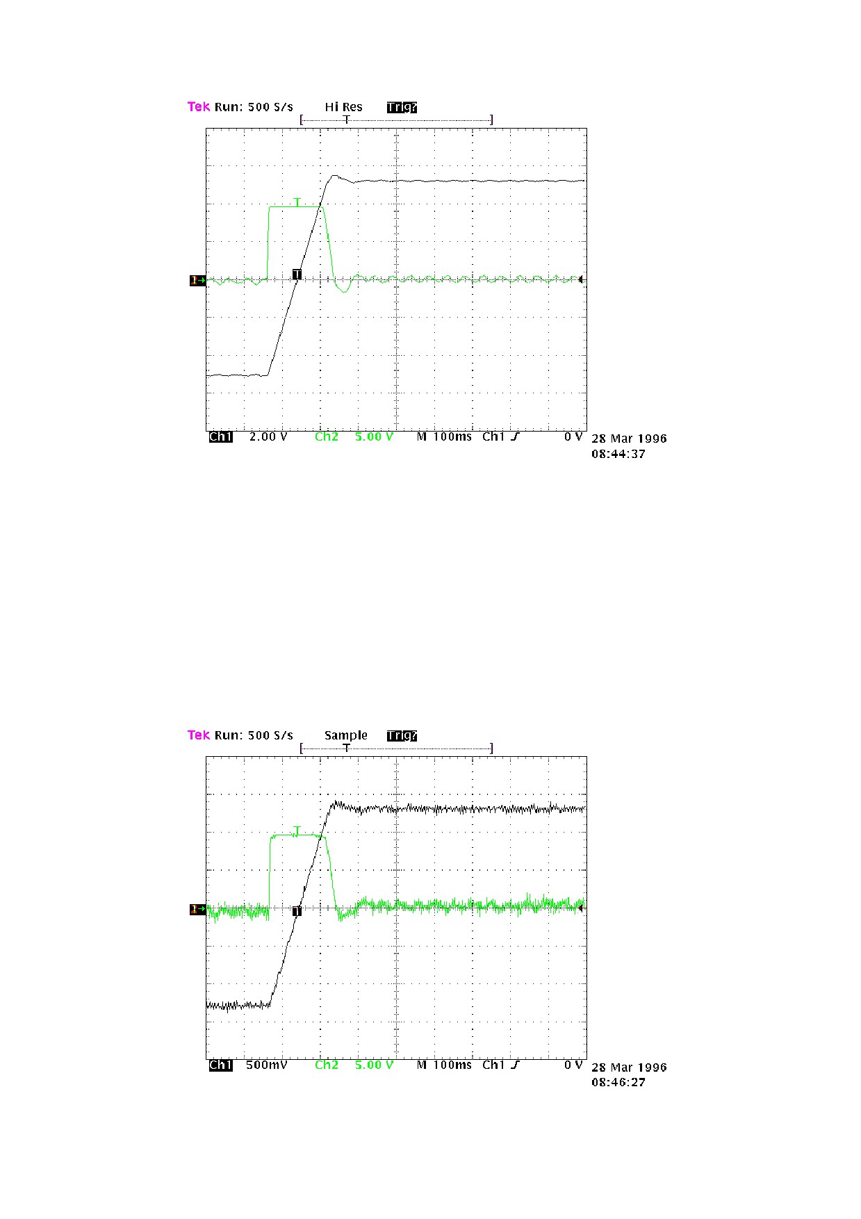
Fig.4
We must therefore obtain approximately 10% overshoot. Make sure that the overshoot is
not followed immediately by undershoot.
Once you have set the optimal value for Pr17 pay attention to the movement of the motor
shaft: if it moves smoothly without vibration and noise, you can deduce that system
calibration procedures are terminated. Otherwise repeat all the previous steps using lower
values for Pr16.
In certain applications you can reduce system acoustic noise levels by raising parameter
Pr18 by a few points. Fig.5 shows that the optimal system response is accompanied by a
current fluctuation that can generate acoustic noise and mechanical vibration; increasing Pr18
to the value 3 will improve this condition significantly (fig. 6).
Fig.5
40
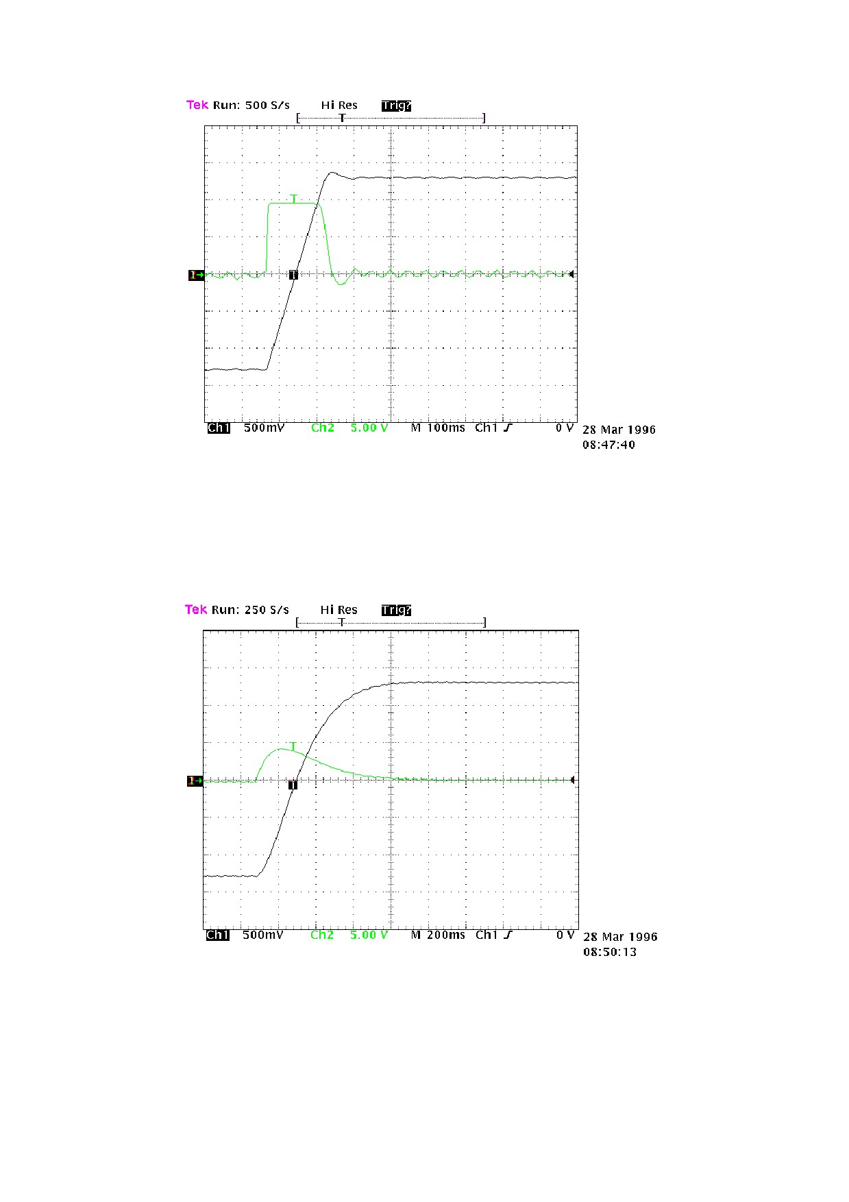
Fig.6
If the driven mechanical system is prone to oscillation, we recommend using very low
values for Pr16; in this configuration the HPD drive will smooth out motor torque requests to
prevent the creation of mechanical oscillation. Figure 7 shows this type of configuration.
Fig.7
41
CALIBRATION WITHOUT INSTRUMENTS
If an oscilloscope is not available, proceed as follows:
A) Calculate the value of Pr16 as described earlier.
B) Calculate Pr17 using the following formula:
135.41⋅Pr16⋅Jtot
Pr17
=1488⋅
Nmpeak
where: Jtot is total inertia (motor + load) in kgm2
Nmpeak is available torque with peak current of the system
C) Start the drive and, moving the axis with an external control change Pr17 to seek the value
at which the axis moves as required.
D) Calculate Pr18 using the following formula:
Pr17
Pr18
=
017⋅
≥
1
Pr16
If the resulting calibration is unsatisfactory, repeat the procedure with lower values for
Pr16.
If the risult is <1, Pr18 must be =1.
42
4.6. Operating modes
Operating modes are selected by means of parameter Pr31, whose default value is 0. Each
operating mode commands a speed loop by means of parameter Pr6 and can limit motor
torque with parameter Pr21 (see block diagrams). Speed control uses Pr7 or Pr6 as a reference
depending on the value of b40.2. Before changing Pr31, b40.2 must be set to 0 to prevent
undesired motor movement; it is now possible to set Pr31 to the value of the chosen operating
mode and load default parameters by means of parameter b99.11. The operating mode will be
enabled by setting b40.2 to 1.
4.6.1. Torque control
This operating mode (1) does not perform “classic” torque control because the speed loop
remains active to monitor limit speed; the torque reference is the main reference Pr7. To set
torque control first program the speed loop to create a stable system. Now set Pr2=1000 (10 V
= 100.0 % torque) b40.0=0 & b40.12=0; b40.2=1 to program the reserved reference, Pr31=1
to enable the operating mode and Pr50 for maximum speed.
PARAMETERS FOR OPERATING MODE 1
Pr50 Maximum speed. Unit=rpm, default=3000, range=0..9000. This parameter makes it
possible to limit maximum absolute motor speed during torque control operation.
4.6.2. Acceleration control
Instead of performing closed loop acceleration control, this mode (2) uses main reference
Pr7 for dynamic modulation of the ramps. To program analogue acceleration control the first
requirement is a stable speed loop. When this is present set Pr2=ACC / 3.2 where ACC is
acceleration in rad/s2 required with a 10V reference signal, b40.0 = 0, b40.12 = 0, b40.2 = 1
and Pr31 = 2. Maximum speed must be programmed in Pr50.
PARAMETERS FOR OPERATING MODE 2
Pr50 Maximum speed. Unit=rpm, default=3000, range=0..9000. This parameter makes it
possible to limit maximum absolute motor speed during operation with acceleration
reference.
Pr55 Acceleration/deceleration
ramp,
read-only
parameter.
Unit=s/krpm,
range=2..30000, resolution=1 thousandth of a second.
43
Pr60:61 Reserved.
Pr62:63 Reserved.
Pr66:67 Reserved.
4.6.3. Low voltage procedure (rel. Sw.41 or more)
This procedure is for those situations in which the operator needs to work in close proximity to the
machine in a situation which could be potentially hazardous. In these conditions, the operator must
move the axes with a lower voltage than the nominal motor voltage (nominal voltage useable: from
90 to 480V~, low voltage: from 48 to 90V~), so that the top speed of the axes is also lowered.
• Setting the drive:
1. Store b40.10=1
2. Autoreset under voltage excluded: b99.8=0
Caution:
The low voltage movement mode is potentially hazardous to the drive when going from
low voltage to nominal operating voltage. This passage must always be done with the
drive disabled, and it is necessary to follow these instructions step by step.
o Low voltage to nominal operating voltage sequence.
a. Disable the drive. Wait 100ms.
b. Change the voltage from low to nominal.
c. Wait 1sec.
d. Enable the drive. The drive will be enabled after about 120ms. The display will
say RUN, and the axis is ready to be checked
o Nominal operating voltage to low voltage sequence.
a. Disable the drive. Wait 100ms.
b. Change the voltage from nominal to low.
c. Wait 1sec.
d. Enable the drive. The drive will be enabled after about 120ms. The display will say
RUN, and the axis is ready to be checked
If during these sequences the display shows the error message ERR2, send the reset command
b99.10=1.
In the previous releases, this procedure only works if there is no backup, and you must wait for the
drive to shut off in the passage from low voltage to nominal voltage and vice versa.
44
4.6.4. Maintenance and commissioning
This operating mode is designed to assist technical personnel during commissioning.
Mode 8 provides various tests to check drive wiring. It’s also possible to move the move
the shaft manually by means of Pr50, b70.1 and b70.2 or using the internal profile generator,
which simplifies speed control loop set-up and ensures that there is no overrun on the
programmed movement. Programming parameters for generating internal profiles are: speed,
motor revolutions, starting position and interval, in seconds, between forward and reverse
movement.
To perform the wiring test the motor must be disconnected from all loads, including inertia
loads; disable the drive via software (b40.9=0), Pr30 must be zero, enable the drive via
hardware and set b70.3=1. The drive will now execute the test routine. When terminated
(b70.3=0), the error code in Pr56 can be displayed after setting Pr57=0.
Error codes:
0
no error
1
b40.9=1 or drive disabled via hardware
2
motor phase sequence and resolver direction incompatible
3
number of motor poles and Pr29 incompatible
4
resolver phase error
5
Pr30 value not zero
99
procedure aborted
By setting the various values in Pr57 you can get other useful information for installation
and maintenance (see table in block diagrams).
PARAMETERS FOR OPERATING MODE 8
Pr50 Manual speed. Unit=rpm, default=100. This speed value is used for manual
movements executed using b70.1 , b70.2 with b70.0=0 and b40.2=1.
Pr51 Profile execution speed. Unit=rpm, default=1000. This is the speed at which the
trapezoidal profile is executed.
Pr52 Distance. Unit=revolutions, default=30. This is the number of revolutions of the
motor shaft that must be performed during generation of the profile.
Pr53 Starting point. Default=1. If set to 1, at start profile (b70.0) the motor will start
rotating and execute Pr52 revolutions with positive speed. If set to 2 the motor will
start rotating and execute Pr52 / 2 revolutions with positive speed. If you set 3 the
motor will start and execute Pr52 revolutions at negative speed.
Pr54 Pause. Unit= tenths of a second, default=1. During execution of the profile the drive
stops between positive speed movement and negative speed movement for an
interval of Pr54 at zero rpm.
Pr55 Deviation factor. During execution of the profile, assuming the same value of Pr16
the optimal value of Pr17 can be achieved by minimising the value of Pr55.
Pr56 Value. Returns information requested with Pr57.
Pr57 Information request. This parameter serves to query the drive. A table of queries is
shown in the block diagram of operating mode 8.
Pr58 Reserved.
Pr59 Reserved.
45
Pr60:61 Reserved.
Pr62:63 Reserved.
Pr64:65 Reserved.
Pr66:67 Reserved.
Pr68:69 Reserved.
b70.0 Start profile. Set 1 to execute the programmed profile. Remember to set b40.2=1 to
effectively switch the speed reference to the control loop.
b70.1 Manual forward speed. If at 1 with b70.0=0 and b40.2=1, the shaft will rotate at the
speed programmed in Pr50.
b70.2 Manual reverse speed. If at 1 with b70.0=0 and b40.2=1, the shaft will rotate at the
speed programmed in Pr50 but in the opposite direction.
b70.3 Wiring test. When you set this command the drive performs a test procedure and
returns the result as an error code that can be viewed using parameters Pr56 and
Pr57. Before entering this command, make sure the motor is disconnected from all
loads, even pure inertia loads. Also ensure that b40.9=0.
b70.4 Reserved.
b70.5 Vibration test. If none of the above functions is active, you can set this bit to one to
evaluate the vibration of the motor shaft, incrementing parameter Pr64 in absolute
terms by a value proportional to the vibration detected. The user is responsible for
evaluating Pr64 and bringing it to zero in relation to the appropriate time interval.
b70.6 Reserved.
b70.7 Reserved.
b70.8 Reserved.
4.6.5. Positioner
Operating mode 9 executes a simple trapezoidal profile. For this profile the user must
define acceleration with Pr51, steady time rpm with Pr52 and displacement using the pair of
long format parameters Pr64 and Pr65. At each profile execution command, b70.8, the motor
executes Pr64:65 steps (one motor revolution is equivalent to 4096 steps). The parameters of
a trapezoidal profile cannot be changed during execution (b70.7=1), except Pr64:65. In the
block diagram note the four different reset types, the availability of servo-error indication and
the possibility of using space control with or without feed forward. The incremental position
must be always positive and movement direction must be selected with parameter b70.1.
Displacement can be defined using the drive frequency input. Additional features are
available using the internal PLC.
Note that the profile execution command is not generated on a constant time base (profile
calculation may require more than 2 milliseconds).
46
PARAMETERS FOR OPERATING MODE 9
Pr50 Pulse input multiplication factor K. Default=1. If b70.9=1 frequency/direction
input pulses are multiplied by Pr50 and the result is added to Pr64:65. The frequency
input direction signal must be forced to a fixed level (logical 0). Refer to the chapter
Frequency input connection for the connection diagrams.
Pr51 Acceleration time. Unit=s/krpm, range=0.002..30.000, resolution=0.001 sec,
default=0.002 S. Acceleration ramp for positioning profile.
Pr52 Rpm at speed. Unit=rpm, default=1000. Steady state speed used during generation
of the positioning profile.
Pr53 Reserved.
Pr54 Reserved.
Pr55 Reserved.
Pr56 Servo-error window. Unit=steps, default=100. If the position error as an absolute
value exceeds the value set in Pr56, b70.5 is set to 1. If b70.5 is utilised it must be
reset by the user following servo errors. This can be achieved, for example, by the
PLC program.
Pr57 Position controller proportional gain. Default=100, range 0..32000.
Pr58 Reserved.
Pr59 Reserved.
Pr60:61 Position controller reference. Unit=steps.
Pr62:63 Motor position. Unit=steps, 4096 steps per revolution.
Pr64:65 Incremental position. Unit=steps. On receipt of the profile request, b70.8, the motor
will execute Pr64:65 steps in the direction set in b70.4.
Pr66:67 Reserved. Cannot be used during profile generation.
Pr68:69 Reserved. Cannot be used during profile generation.
b70.2 Reset incremental position. Resets Pr64:65. This command is useful when the
incremental value is programmed on the frequency input.
b70.4 Forward/Reverse. When the start profile command is transmitted (b70.8) if b70.4=0
the motor will execute Pr64:65 steps in the positive speed direction. If b70.4=1 it will
execute the same number of steps in the negative speed direction.
b70.5 Servo error. b70.5 is set to 1 if the absolute value of the position error is greater than
the value set in Pr56. If utilised, b70.5 must be reset by the user, e.g. using the PLC
program, following servo-errors.
b70.6 Feed-forward enable. Default=0. If set to 1 feed-forward is enabled on the position
controller.
b70.7 Profile in execution. B70.7=1 indicates that the drive is executing a positioning
profile.
b70.8 Start profile. To start positioning.
b70.9 Enable frequency input. Default=0. If set to 1, Pr64:65 can be set on the frequency
input.
b70.10 Reset type 1. Resets motor and reference position. This command is only accepted
when no profile is in execution.
b70.11 Reset type 2. Command to set motor and reference position to equal the absolute
position of the shaft. Accepted only when no profile is in execution.
47
b70.12 Reset type 3. Command to set the reference equal to the motor position. Accepted
only when no profile is in execution.
b70.13 Reserved.
b70.14 Reserved.
b70.15 Reserved.
4.6.6. Digital locking
Operating mode 10 is a tracking function referred to a frequency input signal (connector
X6) set as an encoder signal with b42.5=1; the encoder signal is counted on all A and B signal
switching fronts. The motor position counter increases by 4096 steps each revolution. The
ratio between master and slave can be entered using parameters Pr51 and Pr53. You can also
select the ramp to utilise during catch or release cycles (Pr52), add slip speed (Pr58) and limit
speed demands of the proportional part of the loop (Pr50). Further information available:
master and slave locked and servo-error. Using Pr52, the main ramps and the internal PLC
makes it possible to program various different catch and release modes with or without phase
recuperation. Refer to Frequency input connection chapter for connection diagrams.
PARAMETERS FOR OPERATING MODE 10
Pr50 Maximum speed. Unit=rpm, default=200, range =0..9000. This parameter makes it
possible to limit maximum speed of the motor; it can be used to limit speed during a
catch on fly cycle or during sudden speed changes (see Pr58).
Pr51 Reference multiplication factor. Default=1, range
=-32000..+32000. This
parameter, together with Pr53, makes it possible to set the required ratio for the input
reference frequency.
Pr52 Acceleration/deceleration ramp. Unit=s/krpm, default=500, range=0..30000,
resolution=1 thousandth of a second. The acceleration/deceleration demanded of the
motor can be restricted so that a speed decrease or increase of 1000 rpm takes Pr52
thousandths of a second; this function is useful during catch on fly cycles.
Pr53 Reference division factor. Default=1, range=-32000..+32000. This parameter
together with Pr51 makes it possible to set the required ratio for the input reference
frequency.
Pr54 Reserved.
Pr55 Required speed. Unit=rpm Read-only parameter. Shows the input reference
frequency converted into rpm
Pr56 Servo-error window. Unit=steps, default=100. If the absolute value of the position
error exceeds the value set in Pr56, b70.5 is set to 1. If utilised, b70.5 must be reset
by the user, e.g. by the PLC program, following servo-errors.
Pr57 Position controller proportional gain. Default=100, range 0..32000.
Pr58 Slip speed.
48
Pr59 Reserved.
Pr60:61 Position controller reference. Unit=steps.
Pr62:63 Motor position. Unit=steps, 4096 steps per revolution.
Pr64:65 Reserved.
Pr66:67 Reserved.
Pr68:69 Reserved.
b70.2 Digital locking engaged. During locking with ramp (Pr52) other than zero, this bit
indicates the termination of the transitional phase.
b70.3 Enable position. Default=0. During unlocking b70.3=1 enable position with
Pr61:60.
b70.5 Servo-error. b70.5 is set to 1 if the absolute value of the position error exceeds the
value set in. If utilised, b70.5 must be reset by the user, e.g. by the PLC program,
following servo-errors.
b70.6 Feed-forward. Default=1. If set to
1 feed-forward is enabled on the position
controller.
b70.8 Axis lock/release. With this bit you can lock (=1) or release (=0) the axis from the
input encoder reference.
b70.9 Reserved.
b70.10 Reset type 1. Resets motor and reference position. Implemented only with b70.8=0.
b70.15 Reserved.
4.6.7. Stepper motor emulation
This mode emulates the operation of a stepper motor: each pulse received on the frequency
input (terminal board X6 channel A=frequency, channel B=direction) is multiplied by Pr51
and the result is added to the reference position. The frequency input must be programmed as
a direction/sign signal by setting b42.5=0. Just as in all other operating modes it is possible to
enable feed forward, limit the action of the proportional part, obtain servo-error indication and
select the most suitable type of reset. Note that the frequency count occurs on the negative
front of the signal and changes of the direction signal must be made at least 1 µS before the
negative frequency front. Unlike stepper motors, in this case there is no risk of step loss. Refer
to Frequency input connection chapter for the connection diagrams.
PARAMETERS FOR OPERATING MODE 11
Pr50 Maximum speed. Unit=rpm, default=3000, range=0..9000. This parameter makes it
possible to limit maximum motor speed.
Pr51 Reference multiplication factor. Default=1, range=-0..+4096. This parameter
allows you to set the required multiplication ratio for input reference frequency.
Pr54 Reserved.
Pr56 Servo-error window. Unit=steps, default=100. If the absolute position error is
greater than the value in Pr56, b70.5 is set to 1. If utilised, b70.5 must be reset by the
user, e.g. by the PLC program, following servo-errors.
49
Pr57 Position control loop proportional gain. Default=100, range 0..32000.
Pr60:61 Position control loop reference. Unit=steps.
Pr62:63 Motor position. Unit=steps, 4096 steps per revolution.
Pr64:65 Reserved.
b70.5 Servo-error. b70.5 is set to 1 if the absolute position error is greater than the value
in Pr56. If utilised, b70.5 must be reset by the user, e.g. by the PLC program,
following servo-errors.
b70.6 Feed-forward enable. Default=0. If set to 1 feed-forward is enabled on the position
controller.
b70.8 Axis lock/release. With this bit you can lock (=1) or release (=0) the axis from the
input encoder reference.
b70.9 Reserved.
b70.10 Reset type 1. This command resets motor and reference position.
b70.11 Reset type 2. Sets motor and reference position equal to the absolute shaft position.
b70.12 Reset type 3. Sets the reference equal to the motor position.
50
4.6.8. Spindle orientation
When this mode (12) is selected it becomes operational when b40.2=1. The motor reaches
the speed in Pr50 on the ramps in Pr52. It now spins at constant speed until it reaches the
position set in Pr54; at this point the position loop is closed.
PARAMETERS FOR OPERATING MODE 12
Pr50 Maximum speed during spindle orientation. Unit=rpm, default=200,
range=0..500. This parameter makes it possible to limit maximum motor speed
during spindle orientation.
Pr51 Reserved.
Pr52 Deceleration ramp. Unit=s/krpm, default=500, range=2..30000, resolution=1
thousandth of a second. When the spindle orientation command is set (b40.2=1)
deceleration required of the motor can be limited by this parameter so that a change
of 1000 rpm takes Pr52 thousandths of a second.
Pr53 Reserved.
Pr54 Motor shaft position for spindle orientation. Unit=steps, default=0, range=0..4095.
One revolution of the motor shaft corresponds to 4096 steps.
Pr56 Servo-error window. Unit=steps, default=100. If the absolute position error is
greater than the value set in Pr56, b70.5 is set to 1.
Pr57 Position control loop proportional gain. Default=100, range = 0..32000.
Pr58 Reserved.
Pr59 Reserved.
b70.5 Servo-error. b70.5 is set to 1 if the absolute position error is greater than the value
in Pr56, otherwise it is set to zero.
4.7. Block diagrams
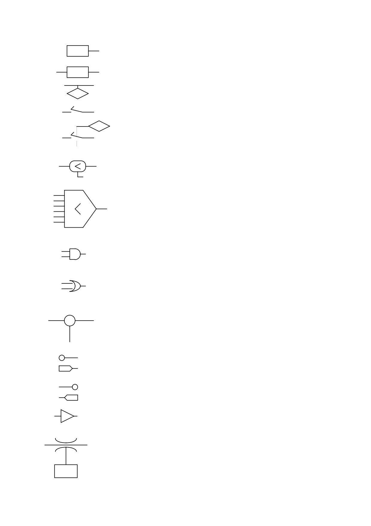
The main block diagram provides a graphic description of how to use the drive. Each
rectangular block represents one or more read/write parameters, each rhomboid shape
represents read-only parameters. In the diagram there are other functional blocks such as:
greater than..., equal to, the smallest among..., logical and/or; we have used standard symbols
for all these blocks. Binary parameters are shown as switches and the position depicted is the
default value.
51
A
Pr X
• Read/write parameter PrX
A = value of PrX
A
B
• Read/write parameter PrX
Pr X
B = value according to values of A and PrX
• Read-only parameter
A
PrX is value of A (can also be binary)
Pr X
• Read/write bit parameter
bx.y
switch position shows bx.y=0
bx.y
• Value of bit parameter bx.y sets the switch
• If A is smaller than B, C =1 (true); otherwise C = 0 (false)
A
B
C
A
B
• The value of G is the lower value among A B C D E and F
C
D
G
E
F
A
• C = 1 only when A = 1 and B = 1; otherwise C = 0
C
B
• If A or B are 1, C = 1
A
C
otherwise C = 0
B
• C = A - B
A
+
C
-
B
• values from hardware
• values to hardware
• Value of A is converted to B. E.g., if the triangle symbol contains
A/D, the analogue value of A is converted into the digital value B
A
B
• Maximum value of A is PrX
A
Pr X
52