Api Pneumatic. GENERAL CATALOG (2019) - page 24
 

  Index      Manuals     Api Pneumatic. GENERAL CATALOG (2019)


Search            copyright infringement  


Content      ..     22      23      24      25     ..


Api Pneumatic. GENERAL CATALOG (2019) - page 24


2

Rotary actuators with ball valve

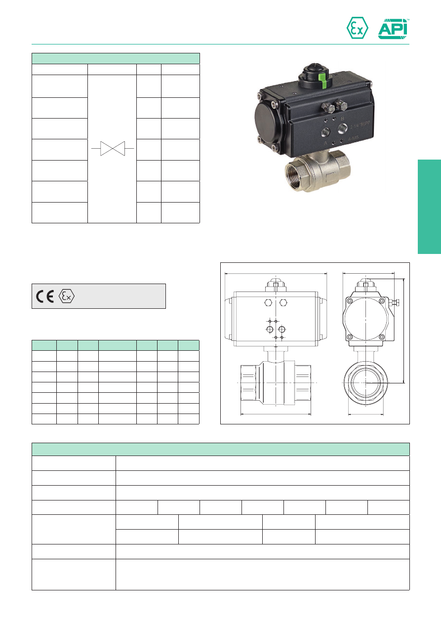
Stainless steel ball valves with actuator double acting

2.431.11

F

B

A

D

C

Standard executions

Version

Symbol

Code

Item

3/8”

811021

VSI2038DE

1/2”

811022

VSI2012DE

3/4”

811023

VSI2034DE

1”

811024

VSI2100DE

1 1/4”

811025

VSI2114DE

1 1/2”

811026

VSI2112DE

2”

811027

VSI2200DE

Size

A

B

Ø actuator

C

D

F

G3/8

27

65

32

105

45

118

G1/2

27

75

32

105

45

118

G3/4

33

80

32

109

45

118

G1

41

90

40

132

65

120

G1 1/4

50

110

52

150

71,5

147

G1 1/2

58

120

63

175,5

83

168

G2

70

140

75

196,5

95

184

Technical data of the ball valve

Fluid

Compressed air, water, inert gases, fluids, steam

Pressure range

63 bar 

Temperature range

-20 °C ÷ + 150°C

Orifice

3/8”= 10 mm

1/2”= 15 mm

3/4”= 20 mm

1”= 25 mm

1 1/4”= 32 mm 1 1/2”= 40 mm 2”= 50 mm

Flow

3/8”= 3.000 l/min

1/2”= 11.500 l/min

3/4”= 21.000 l/min 1”= 33.000 l/min

1 1/4”= 50.000 l/min

1 1/2”= 84.000 l/min

2”= 97.000 l/min.

Mounting

In-line

Materials

Body: 

Steel Inox AISI 316

Ball: 

Steel Inox AISI 316

Seals: 

PTFE - FKM

Manufactured according to 2014/34/EU - 

ATEX

II 2Gc IIC T6
II 2Dc T85°C

Series of stainless steel ball valves “full bore” with rotary actuator
double acting.
For actuator features 

see page 2.430.10.

For NAMUR solenoid valve 

see page 2.88.1.

For actuator mounting accessories 

see page 2.431.30.

Rotary actuators with ball valve

Limit switch box

2.431.30

Aluminum switch boxes painted with epox powder black (SB200 and SB300), supplied complete with universal adjustable brackets 
for assembly on our full range of actuators (L=30x80/130-H=20/30).
These devices are particularly suitable for monitoring the position of each valve, even at long distances, they can contains mechanical 
or proximity limit switches.
SB200 and SB500 are supplied with tridimensional position indicator yellow/red and 8 wire points standard (two free for eventual 
electrovalve attachment in box). SB700 is supplied with tridimensional position indicator green/red and 10 wire-points standard (four  
free for eventual electrovalve attachment in box). There is plenty of room to facilitate all wiring procedures, on installation.
Screws on the box cover are self-locking and unlosable, cam easy to set without tools, don’t need any further adjustment after initial 
setting. 

Technical data dei box di finecorsa

Class protection

 SB200: IP67  -  SB500: IP66  -  SB700: IP65  

Temperature range

SB200: -25°C ÷ +80°C 

SB500: -20°C ÷ +50°C (standard),  -40°C ÷ +50°C (option)

SB700: -15°C ÷ +80°C

Connections

SB200 - SB500: M20x1.5 (x2)   

SB700: 1/2” G (x2)

Terminal strip

SB200 - SB500: 8 wire points   

SB700: 10 wire points

Position indicator

0° ÷ 90°

Open / Closed

SB200 - SB500: Yellow / Red 

SB700: Green / Red

Materials

SB200 - SB500

SB700

Cover:
Body:
Shaft:
Indicator cover:
Indicator:
Terminal strip:
Cam:
Spring:
Screws:
O-ring;
Earthing screw:

  Aluminium alloy
  Aluminium alloy
  Stainless steel
 Polycarbonate
  ABS, polycarbonate
  Polycarbonate, brass, stainless steel
 Polycarbonate
  Stainless steel
  Stainless steel
 NBR
  Stainless steel  

 Polycarbonate
 PPO
 PA
 ABS
 ABS
 -
 Polycarbonate
  Stainless steel
  Stainless steel
 NBR
 -

Standard executions

Version

Limit switch code

Code

Item

SB200

ZM50G10B01

811188

SB200M012

ZM10G10B01

811189

SB200M022

NBB2-V3-E2

811190

SB200P112

IS5076

811191

SB200P122

NCB2-V3-NO

811192

SB200P132

ALMS-5-240

811193

SB200Q512

SB500

83261

811194

SB500M032

83268

811195

SB500M042

NBBB2-V3-E2

811196

SB500P112

IS 5076

811197

SB500P122

NCB2-V3-NO

811198

SB500P132

ALMS-5-240

811199

SB500Q512

SB700

LS SILVER

811200

SB700M052

NBBB2-V3-E2

811208

SB700P112

IS576

811209

SB700P122

NCB2-V3-NO

811210

SB700P132

SB500 supplied according to 2014/34/EU - 

ATEX

II 2G Ex db IIB T6 Gb

2

Rotary actuators with ball valve

Limit switch box SB 200

2.431.31

88

1

17,7

32

7

3

80 / 130

Ø 9,5

Ø 5

M20x1,5

112

130

80

4

5/

5

5/

6

5/

75

30

4

44

Mechanical

Proximity

Magnetic

Code

811188

811189

811190

811191

811192

811193

Item

SB200M012

SB200M022

SB200P112

SB200P122

SB200P132

SB200Q512

Limit switch manufacturer

Honeywell

Pepprl Fuchs

IFM

Pepperl Fuchs

ALMS

Limit switch code

QM50G10B01

QM50G10B01-G

NBB2-V3-E2

IS5076

NCB2-V3-NO

ALMS-5-240

Ex identication

-

Ex ia IICT6

-

Ex ia IICT6

-

Contacts

Silver

Gold

-

-

Function

SPDT

PNP

PNP / NPN

NAMUR NC

-

Number of wires

3

3

2

2

3

Voltage

125 ÷ 250 VAC

0 ÷ 125 VAC

10 ÷ 30 VDC

5 ÷ 36 VDC

8 VDC

5 ÷ 240 V AC/DC

Intensity

5 A

0,1 A

0 ÷ 100 mA

0 ÷ 200 mA

-

≤ 300 mA

Switching frequency

-

0 ÷ 1000 Hz

0 ÷ 2000 Hz

0 ÷ 2000 Hz

60 Hz

N° wiring diagram

1

2

2/3

4

5

Limit switch code

01

02

11

12

13

51

Q.ty of limit switch

2

2

2

2

2

2

Type: 

SB200

Rotary actuators with ball valve

Limit switch box SB 500

2.431.32

127,6

27

7

3

Ø 9,5

Ø 5

4

M20x1.5

112,1

143

80 / 130

30

60

40 / 50

130

80

Mechanical

Proximity

Magnetic

Code

811194

811195

811196

811197

811198

811199

Item

SB500M012

SB500M022

SB500P112

SB500P122

SB500P132

SB500Q512

Limit switch manufacturer

Honeywell

Pepprl Fuchs

IFM

Pepperl Fuchs

ALMS

Limit switch code

V15T16SZ200A05

QM50G10B01-G

NBB2-V3-E2

IS5076

NCB2-V3-NO

ALMS-5-240

Ex identication

-

Ex ia IICT6

-

Ex ia IICT6

-

Contacts

Silver

Gold

-

-

Function

SPDT

PNP

PNP / NPN

NAMUR NC

-

Number of wires

3

3

2

2

3

Voltage

125 ÷ 250 VAC

30 VAC / 125 VAC

10 ÷ 30 VDC

5 ÷ 36 VDC

8 VDC

5 ÷ 240 V AC/DC

Intensity

16 A

0,1 A

0 ÷ 100 mA

0 ÷ 200 mA

-

≤ 300 mA

Switching frequency

-

0 ÷ 1000 Hz

0 ÷ 2000 Hz

0 ÷ 2000 Hz

60 Hz

N° wiring diagram

1

2

2/3

4

5

Limit switch code

03

04

11

12

13

51

Q.ty of limit switch

2

2

2

2

2

2

Type: 

SB500

2

Rotary actuators with ball valve

Limit switch box SB 700

1/2” G

91

84

116

91

20

30

40

50

78

47

30

130

80

Ø


4,7

Ø


14

4

Mechanical

Proximity

Code

811200

811208

811209

811210

Item

SB700M052

SB700P112

SB700P122

SB700P132

Limit switch manufacturer

E-switch 

Pepprl Fuchs

IFM

Pepperl Fuchs

Limit switch code

LS silver

NBB2-V3-E2

IS5076

NCB2-V3-NO

Ex identication

-

Ex ia IICT6

-

Ex ia IICT6

Contacts

Silver

-

-

-

Function

SPDT

NPN

PNP / NPN

NAMUR NC

Number of wires

3

3

2

2

Voltage

125 ÷ 250 VAC

10 ÷ 30 VDC

5 ÷ 36 VDC

8 VDC

Intensity

15 A

0 ÷ 100 mA

0 ÷ 200 mA

-

Switching frequency

-

0 ÷ 1000 Hz

0 ÷ 2000 Hz

0 ÷ 2000 Hz

N° wiring diagram

1

2

3

4

Limit switch code

05

11

12

13

Q.ty of limit switch

2

2

2

2

Type: 

SB700

2.431.33

Rotary actuators with ball valve

Limit switch box - Wiring diagram

2.431.34

1

2

3

4

5

6

7

8

Closed

Open

Ext

Red 
Black
Green 
Yellov
White 
Blue

NC

C

NO

NC

C

NO

Ground

Top switch

Bottom switch

Solenoid valve

Ground

Solenoid valve

Ground

Solenoid valve

Ground

Solenoid valve

1

2

3

4

5

6

7

8

1

2

3

4

5

6

7

8

1

2

3

4

5

6

7

8

1

2

3

4

5

6

7

8

Clos

eO

pen

Ext

Red
Black
Green
Yellow 
White
Blue 

NC
C
NO

NC
C
NO

Ground

Top switch

Bottom switch

Solenoid valve

Top switch

Bottom switch

Top switch

Bottom switch

Top switch

Bottom switch

Red
Yellow
Black 
Red 
Yellow 
Black 

Red 
Yellow
Black 
Red
Yellow

+ Brown 

- Blue

+ Brown

- Blue 

+

-

Black

DC24V

(10~30 VDC)

DC24V

(10~30 VDC)

DC24V

(10~30 VDC)

DC24V

(10~30 VDC)

≤ 150mA

≤ 150mA

≤ 150mA

≤ 150mA

8 VDC

8 VDC

Clos

eO

pen

Ext

Red 

Yellow

Red

Yellow 

Red 

Yellow 

Red 

Yellow 

Red 

Yellow 

Red 

Yellow 

Top Switch

Bottom Switch

Top Switch

Bottom Switch

Top Switch

Bottom Switch

Top Switch

Bottom Switch

Top Switch

Bottom Switch

N° wiring diagram: 

1

Function: SPDT

Type: Mechanical

N° wiring diagram: 

2

Function: PNP

Type: Proximity

N° wiring diagram: 

3

Function: NPN

Type: Proximity

N° wiring diagram: 

4

Function: 

NAMUR CN

Type: Proximity

N° wiring diagram: 

5

Function: SPDT

Type: Magnetic

Rotary actuators with ball valve

Handweel manipulator

2.432.1

Series of new generation handweel manipulators, compact and universal, with IP67 protection.
The design of these manipulators allow to chose on positioning between valve and actuator, function of manipulator can be reversed.

Manipulator is placed between valve and actuator: valve pin can be directly mounted to the actuator pinion through the manipulator 
body, or by an adaptor (in case a bracket should be applied).
During automatic working, handweel is off; connecting the manual function, the handweel will move both the ball-valve and the
actuator.

D1

D2

D3

D4

A

B

C

G

D

D

L

F

Ch2

Ch1

E

H1

H2

H3

H4

Standard executions

Version

Code

Item

Ø 50

811168

GDB050

Ø 70

811169

GDB070

Ø 102

811170

GDB102

Ø 140

811171

GDB140

Ø 165

811173

GDB165

Ø 254

811174

GDB254

Item

A

B

C

E

F

G

L

D1

H1

D2

H2

D3

H3

D4

H4

Ch1

Ch2

GDB050

90

110

125

Ø 200

44

100

143

Ø 50

Ø 8,5

Ø 70

Ø 6,5

Ø 70

M8x12

Ø 50

M6x10

14

17

GDB070

125

135

150

Ø 200

52

118

177

Ø 70

Ø 11

Ø 102 Ø 8,5 Ø 102 M10x15 Ø 70

M8x12

14

17

GDB102

140

160

185

Ø 300

85

124

190

Ø 102

Ø 13

Ø 125

Ø 11

Ø 125 M12x18 Ø 102 M10x15

22

27

GDB140

185

200

230

Ø 400

85

162

325

Ø 102

Ø 17

Ø 140

Ø 11

Ø 140 M16x24 Ø 102 M10x15

27

36

GDB165

230

243

268

Ø 600

104

181

395

-

Ø 21

Ø 165

-

Ø 140 M16x24

-

-

36

36

GDB254

265

283

330

Ø 700

130

205

400

Ø 165

Ø 21

Ø 254

Ø 17

Ø 254 M20x30 Ø 165 M16x24

46

60

Item

Gear ratio

Output torque

GDB050

1 : 40

300 Nm

GDB070

1 : 38

360 Nm

GDB102

1 : 36

810 Nm

GDB140

1 : 50

1.310 Nm

GDB165

1 : 55

2.800 Nm

GDB254

1 : 62

5.500 Nm

Technical data

Materials

Handle: 

Carbon steel

Worm shaft: 

C45

Handwheel: 

Grey cast iron

Positioning screw: 

Carbon steel

Worm gear: 

Steel

Bracket cap: 

Grey cast iron

Body: 

Grey cast iron

3

Airline equipment and pressure-gauges 

3

3.0

0

1

2

4

5

6

7

8

0

1

2

3

4

5

6

7

8

9

10

11

12

13

14

15

16

17

18

19

mm

in

mm

Airline equipment and pressure-gauges 

Technical data

from page 3.1.1

Size 1/4”

Size 3/8”

Size 1/2”

from page 3.2.1

Accessories, assembling
kits and spare parts

from page 3.5.1

Size 1”

from page 3.2.30

from page 3.2.10

from page 3.2.20

Microregulators 1/8”, 1/4”

from page 3.10.1

Modular soft-start valve

 from page 3.3.1

Analog Pressure-gauges 
and vacuum-gauges

Digital Pressure-gauges 
and vacuum-gauges

from page 3.50.1

from page 3.60.1

from page 3.70.1

Digital Pressure Switch

3.1.1

Airline equipment

Technical data

TREATMENT OF THE COMPRESSED AIR

The air destined for use in pneumatic devices must be suitably prepared.

It is taken from the surrounding environment for introduction into the compressor and is rich in impurities and water 
vapour.

The compressor itself inevitably releases lubricating oil into the air, which is very dangerous for the seals of the 
pneumatic components.

Following passage through the compressor, the compressed air is always stored in a large tank that has a dual 
function: to even out oscillations in pressure and to cool the compressed air.

Indeed, the high temperatures reached at the end of the compression process aid the evaporation of the water in 
the air against the condensing effect of the high pressures.

For these reasons, the tank located downstream of the compressor must be of a suitable size: in particular, in the 
case in which the compressor is volumetric and a high quantity of air is taken up.

It is very important that the compressed air has time to cool, allowing the water vapour contained in it to condense 
on the bottom of the tank, as it is considerably more convenient to eliminate as much of the water vapour as possible 
during this stage.

Even with these precautions, the percentage of humidity present in the compressed air remains important. Indeed, 
during distribution along the pipes, further condensation occurs, due to the further cooling of the air and despite the 
falls in pressure that aid the dissolution of the water.

For this reason the distribution pipes must be slightly inclined (~2%) and feature umbrella-handle pipes at regular 
intervals that lead to small condensation collection tanks. 

Particular attention must be paid to the lubricating oil, especially in the case of centrifugal compressors: it must be 
eliminated by means of appropriate oil extraction filters at the exit of the compressor.

The humidity of the air causes rust and corrosion in the metal pipes, deposits in the pneumatic devices and the 
formation of sleeves of ice at the discharge points in particular atmospheric conditions and for high-frequency use.

The operating safety and lifespan of the pneumatic devices depend to a considerable degree upon the proper prepa-
ration of the compressed air that feeds them, which is obtained by means of a series of devices that are located 
upstream of the part of the apparatus described so far, but before the actual pneumatic system. 

The 

DEVICES FOR THE TREATMENT OF THE COMPRESSED AIR

 are basically constituted by: 

FILTERS, 

PRESSURE REGULATORS, LUBRICATORS;

 and by extension, their components: 

MANOMETERS, 

PROGRESSIVE STARTING VALVES, INSERTION AND SECTIONING VALVES AND TANKS.

3

3.1.2

Airline equipment

Technical data

It is advisable to choose a filter of such dimensions that, at the requested flow, the fall in pressure is maintained 
within the limits indicated above. In this case the filter also works well for the separation of the condensation. 
An under-sized filter causes excessive falls in pressure, whilst the filtering effect is poor.
Normally a filter capable of providing the required flow, without high filtering capacities, but suitable for the supply of 
compressed air to the valves and pneumatic cylinders, is installed at the beginning of a system. Filters that provide 
better quality air are installed downstream of the derived devices - with a lower flow - that require it.

Pressure

(bar)

0

400

800

1200

1600   

2000

8

7

6

5

4

3

2

1

Flow (Nl/min)

Type: 

A12F

CHOOSING THE SIZE OF THE FILTERS

It is necessary to adapt the filters to the flow required by the system, 
or section of the system, which they feed.
The characteristic 

“FALL IN PRESSURE - FLOW” 

curves of the 

filter are used for this purpose. They associate the variation in the 
falls in pressure around the filter with the variation of the flow and 
indicate the range of use (useful flow interval) of the component in 
an immediately comprehensible manner.
The range of use increases with the increase in the dimensions of 
the filter (of its ports).

FILTERS

The impurities contained in the air: waste materials, powder, rust and humidity that condenses, can cause serious 
damage to the pneumatic components, compromising their functioning and duration, as they facilitate the wear of 
the flowing surfaces and the seals.
The 

FILTERS

 have the important function of purifying the compressed air of solid particles and, as a collateral effect 

associated with their operating characteristics, also of a percentage of the liquid ones.
The filters are constituted by: a body with threaded ports, a transparent cup screwed onto it and a filtering cartridge.
The compressed air to be filtered is conveyed in a tangential direction from the supply mouth to the cup, where it 
assumes a cyclonic movement which enables the separation of the larger solid particles and a good part of the liquid 
particles; both collect on the bottom of the cup, from where they are discharged on a regular basis. 
The finer solid particles, on the other hand, are captured by the filtering cartridge, which is made from sintered mate-
rial (bronze, ceramic material& ).
Depending on its characteristics, the filtering cartridge captures solid particles of an average diameter of 40, 20 or 
5 micron.
It is not possible 

in any case

 to restrain the liquid particles that do not collect on the bottom of the cup as they are 

drawn and pass the barrier.
Consequently the effect of separation of the condensation, which is introduced by the filter, is a secondary one; it is 
necessary to take care to discharge the condensation that is produced otherwise a dynamic equilibrium is produced 
in which as much condensation is removed as is produced. 
The filters are normally equipped with a separator, beneath the cartridge, whose task is to keep the slimy liquid 
deposited still; levels above the separator must be discharged.
It is always advisable to choose a larger size filter in order to have the benefits of a large cup, considerable cooling 
of the air and good separation of the impurities.
It is NOT in any case possible to hold back sufficient liquid particles to achieve the effective extraction of oil from 
the air: it is just a matter of time before the oil, which is not filtered upstream, reaches the pneumatic components. 
A considerable percentage of humidity will also always be present in the air downstream of the filter. In order to 
eliminate the oil of the air compressor, it is necessary to adopt special oil extraction filters. 
The choice of the cartridge depends on the degree of cleanliness necessary for the air to be used in the system.
The more complex the system, with small and fast-moving components, the greater must be the degree of filtration 
of the cartridge.
The ideal filter is a component that does not introduce falls in pressure. Actually, a fall of pressure always exists 
around a filter and depends largely on the degree of filtration.
It is advisable to limit the fall of pressure to 0.2 ÷ 0.3 bar, as the production costs of compressed air are very high 
and, if it is wished to maintain the supply pressure of the components constant, each fall in pressure translates into 
greater pressure to be generated by the compressor.
The filtering cartridge gets dirty very easily: if cleaning is neglected the flow of air across the filter can be greatly 
reduced; furthermore, in order to minimize falls in pressure, it is wise to clean it frequently, removing the grease 
from it and drying it.

3.1.3

Airline equipment

Technical data

PRESSURE REGULATORS

Pressure adjustment is always necessary upstream of a pneumatic device: it prevents falls of pressure in the net-
work from distorting the conditions of use.

The performance of valves and pneumatic cylinders are highly dependant on the value of the supply pressure. Some 
components require precise and constant pressures in order to work properly.

A pressure regulator is always installed upstream of the system, and its task is to maintain the operating pressure 
at the output opening constant with the variation of the flow and the constant pressure in the tank.

Rapid and considerable variations in flow, corresponding to consumption peaks, tend to cause falls in pressure that 
can be controlled by the use of suitably sized reserve tanks.

The reduced operating pressure is less than the output pressure of the compressor; both must be appropriately con-
trolled. Indeed, whilst it is true that lower material costs and, at an equivalent power, lower flows of used air would 
be incurred by making the pneumatic components function at high pressure, it is equally true that the production 
costs of compressed air are very high and increase considerably with the increase in the value of the pressure at 
which the air is supplied.

If the thermodynamic efficiency of the compressor - which is notoriously bad and decreases with the increase in the 
final pressure - is multiplied by the bad conversion efficiency of mechanical energy into pressure energy, a very low 
final efficiency figure is obtained that justifies the high production costs of compressed air.

In addition, it is necessary to consider the fact that it is, in practice, impossible to eliminate the losses of compressed 
air, which increase proportionately with the pressure.

On average, a system can lose up 20% of its compressed air through bad connections in correspondence with 
fittings and plugs.

In the presence of two cost causes, one increasing and the other decreasing in relation to the pressure, it is possible 
to identify a pressure value that corresponds to the minimum cost. 

The optimum 

operating

 pressure has long been established as 

6 bar

. The pressure in the tank must be that much 

higher in order to guarantee its cooling and energy flywheel functions.

Pressure regulators are basically constituted by:
-   a body, divided into a bell (with hand-wheel for adjustments and spring) and an actual valve body (with obturator 

disc) equipped with threaded openings.

-   a membrane between the two parts.
The air that arrives from the supply port is blocked (or allowed to pass) by an obturator disc which is opened and 
closed by means of a small rod controlled by the membrane in equilibrium between the two forces: one, above, 
(caused by a charged spring or a pressure) that is preset; the other, below, caused by the reduced pressure in the 
pipe downstream of the regulator.
Each variation in flow causes a temporary variation of the reduced pressure and thus an imbalance in these two 
forces that causes the movement of the membrane with the consequent opening or closure of the disc.
A reduction in flow causes the following temporary effects: an increase in the reduced pressure with the closure of 
the disc; an increase in the pressure fall, due to the reduction of the passage space and a decrease in the reduced 
pressure, with oscillations around the point of equilibrium, until it returns the previous value, which is the only one 
capable of balancing the preset force. 
An increase in flow causes: a decrease in the reduced pressure; the opening of the disc; a decrease in the pressure 
fall, due to the increased passage space and an increase in the reduced pressure until it returns to the previous 
value. 

In both cases the pressure regulator restores the conditions of equilibrium with a new position of the obturator disc, 
which is suited to the changed flow demand.

In the case of constant supply pressure and highly variable flows, the pressure regulators are 

self-adjusting

; i.e. 

they maintain the reduced pressure basically constant.

The greater the dimensions of the membrane, the greater the sensitivity of the reducer and its ability to maintain the 
reduced pressure constant.

3

3.1.4

Airline equipment

Technical data

LUBRICATORS

The pneumatic devices are equipped with mechanical organs with relative movement and consequently require 
lubrication, which is also important in order to limit wear of the seals.
Valves and pneumatic cylinders are currently supplied with 

assembly lubrication

, which is capable of ensuring 

them a long life 

in normal working conditions

.

Lubrication is necessary in the case of pneumatic tools and particular working conditions (e.g. components that oper-
ate at high speeds or in the presence of high temperatures, which are conditions that cause the assembly lubrication 
to evaporate and be removed by the air).
Lubrication is performed by lubricating the air that flows through the components with mineral oil that does not con-
tain additives that could corrode the seals.
The task of the

 LUBRICATORS

 is to dose the air with a certain quantity of nebulized oil.

The air itself transports the oil along stretches of piping, the length of which increases as the size of the drops of 
the micro-mist decrease. 
The lubricators are made up of:
- a body with threaded ports, containing a Venturi connected by means of a small tube
- a cup, to be screwed onto the body, into which the lubricating oil is poured.
The air, entering from the supply opening, crosses the Venturi constriction, where it creates a reduction in pressure 
that draws the oil from the cup through the small tube, nebulizing it and sending into the pipes.
An adjustment screw makes it possible to regulate the quantity of oil introduced. 
There is a 

minimum operating flow

, characteristic of each range of lubricators, beneath which a sufficient fall in 

pressure is not achieved in the constriction and consequently the oil is not drawn.

CHOOSING THE SIZE OF THE LUBRICATORS

The characteristic 

“FALL IN PRESSURE - FLOW”

 curves are used for this purpose as they permit the rapid iden-

tification of the range of use.
It is advisable to choose the lubricator in such a way as to limit the falls of pressure.
The flows provided are, as always, associated with the dimensions and thus to the ports of the lubricator. 

The range of use of the regulator is associated with the dimensions of the ports used (standardized) and thus to 
the dimensions of the regulator. In order to achieve sensitivity, speed of response and small falls, it is necessary to 
choose large bodies with large membranes.
Two basic types of regulators can be identified:
- precision regulators, with large membranes
- commercial regulators, where the aesthetic aspect is important.

In order to achieve the most precise and easiest setting of the pressure, various 

ranges of reduced pressure 

are 

supplied for each type of regulator, by equipping them with pre-charging springs with different elastic constants.

Another significant construction characteristic for the choice of a regulator is the presence of a device that enables 
excess pressure in relation to the preset reduced value to be discharged into the atmosphere; in the absence of flow, 
this is achieved by simply varying the charge of the spring.

This process, known as 

relieving

, consists in equipping the membrane with a hole with a seal upon which the 

controlled rod rests. As the disc reaches the end of its stroke against the closure opening, each further increase in 
pressure raises the membrane above the rod, releasing the air from a hole in the bell until equilibrium is restored.

Pressure

(bar)

0

400

800

1200

1600   

2000

8

7

6

5

4

3

2

1

Flow (Nl/min)

Type: 

A12RR

CHOOSING THE SIZE OF THE PRESSURE REGULATORS

The characteristic 

“FALL IN REDUCED PRESSURE - FLOW” 

curves are 

used for this purpose as they provide the range of use of the component in 
an immediately comprehensible manner.
It is always advisable to choose a regulator capable of supplying the flow of 
air required by the system, upstream of which it is installed, with as low a 
possible fall in reduced pressure: max. 0.5 bar.

3

3.2.1

Airline equipment

1/4”

Series of modular units with the following standard features :
- Regulators with relieving valve
- Filters standard with 25

µ

 cartridge

- Filters with semi-automatic condense drain
- Cup with protection

The gauges are to be ordered separately; for gauges see from 
page 3.50.1

For mounting accessories, assembling kits and spare parts see 
from page 3.5.1

How to order: A14FRR5TM

Standard executions

Version

Symbol

Code

Item

Filter-
regulator 
+ lubricator

090100

A14FRRL

Filter-
regulator

090101

A14FRR

Filter

090102

A14F

Regulator

090103

A14R

Lubricator

090104

A14L

Technical data

Fluid

Compressed air

Maximum pressure

10 bar

Regulation range

0,5 ÷ 8,5 bar

Flow at 6 bar (Nl/min)

A14FRRL = 500; A14FRR = 750; A14F = 750; A14R = 550; A14L = 800

Temperature range

0 ÷ 60 °C

Suggested oil

With ISO VG 32 viscosity conforming to ISO 3448 standards

Cup capacity

Filter : 15 cm

3

    Lubricator : 25 cm

3

Filtering element

Standard 25 µ - On request 5 µ

Condense drain

Standard semi-automatic

Materials

Body and cup protection: 

Painted aluminium

Regulation group: 

Plastic

Condense drain: 

Nickel plated brass

Filtering element: 

Sintered bronze

Diaphragm: 

Nitrile rubber (NBR)

Cup and sight glass: 

Polycarbonate

Springs: Steel

Options 

Suffix

Filter 5 µ cartridge

5

Metal cup

TM

With regulation range 0,5÷4 bar

04

A14FRR

5

TM

Version

Option

Option

3.2.2

Airline equipment

1/4”

Version

Symbol

Code

Item

Filter-regulator

090101

A14FRR

Version

Symbol

Code

Item

Filter-regulator 

+

lubricator

090100 A14FRRL

3

3.2.3

Airline equipment

1/4”

Version

Symbol

Code

Item

Regulator

090103

A14R

Version

Symbol

Code

Item

Filter

090102

A14F


Content      ..     22      23      24      25     ..