Api Pneumatic. GENERAL CATALOG (2019) - page 22
 

  Index      Manuals     Api Pneumatic. GENERAL CATALOG (2019)


Search            copyright infringement  


Content      ..     20      21      22      23     ..


Api Pneumatic. GENERAL CATALOG (2019) - page 22


2

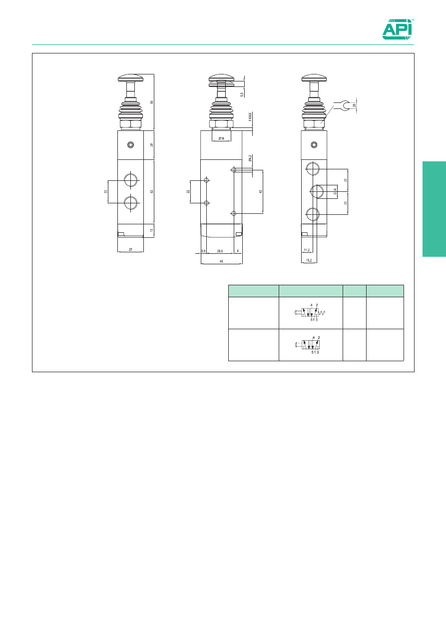
Valves series A1

1/4”, 5/2 - 5/3, manually operated

2.239.4

Version

Symbol

Code

Item

5/2 push-pull,

1 position

034106 A1MA250TT

5/2 push-pull,

2 positions

034107 A1MA251TT

2

2.250.10

Foot operated valves 1/4”

1/4”, 3/2 and 5/2 foot single and two stable position

Series of pedals with 3/2 or 5/2 valve, single and two stable 
position.
In the standard version they are provided with 1/4” spool valve 
and yellow shock-resistant protection in acetal resin and safety 
device to avoid possible improper actuations.

Type:  

AVP2...

Standard executions

Version

Symbol

Code

Item

3/2, normally 
closed, 1 position 
with safety device

2

1

3

033127

AVP230

3/2 normally 
closed, 2 positions 
with safety device

2

1

3

I

033128

AVP232

5/2, 1 position 
with safety device

4 2

51 3

033129

AVP250

5/2, 2 positions 
with safety device

4 2

513

I

033133

AVP251

Technical data

Fluid

Compressed filtered air with or without lubrication. Lubrication, if started, must be continued.

Pressure range

2,5 ÷ 10 bar

Temperature range

0 °C ÷ + 50 °C

Orifice

6,5 mm

Flow

1000 Nl/min

Operating force

50 N

Materials

Housing: 

Shock-resistant acetal resin

Valve body: 

Profiled anodised aluminium

Valve internal parts: 

Nickel plated brass/Nickel plated aluminium/Stainless steel

Seals:                                NBR

Protection cover: 

Shock-resistant acetal resin

1/4”G

2.255.1

Microvalves Ø 4 and manual operating devices

Microvalves Ø 4, 3/2 normally open and normally closed

Series of poppet microvalves arranged for operating manually.
Connections with integral 4 mm push-in fittings.
According to the application you can choose between the ver-
sion with bottom connections or with side ones.

For the choice of the operating device 

see page 2.265.1.

Type:  

AM04132A 
AM04132C

Type:  

AM04132AL 
AM04132CL

Standard executions

Version

Symbol

Code

Item

Normally open

2

1

3

030251

AM04132A

Normally closed

030252

AM04132C

Normally open 
with side 
connections

2

1

3

030253 AM04132AL

Normally closed 
with side 
connections

030254 AM04132CL

Technical data

Fluid

Compressed filtered air with or without lubrication. Lubrication, if started, must be continued.

Pressure range

0 ÷ 8 bar

Temperature range

-20 °C ÷ + 80 °C

Operating force

5 N

Flow

80 Nl/min.

Connections

With integral 4 mm push-in fittings

Fixing

Through 2 holes (Ø 4 mm) on the body

Through 1 hole (Ø 22 mm) on panel (with operating device mounted)

Mounting

In any position

Materials

Body: 

Acetal resin

Seals: 

Nitrile rubber (NBR)

2

2.260.1

Microvalves Ø 4 and manual operating devices

Microvalves Ø 4, 5/2 one position

Series of poppet microvalves arranged for operating manually.
Connections with integral 4 mm push-in fittings.
According to the application you can choose between the 
version with bottom connections or with side ones.

For the choice of the operating device 

see page 2.265.1.

Type:  

AM041520

Type:  

AM041520L

Standard executions

Version

Symbol

Code

Item

5/2, 1 position

030261

AM041520

5/2, 1 position 
with side 
connections

030262 AM041520L

Technical data

Fluid

Compressed filtered air with or without lubrication. Lubrication, if started, must be continued.

Pressure range

0 ÷ 8 bar

Temperature range

-20 °C ÷ + 80 °C

Operating force

10 N

Flow

80 Nl/min.

Connections

With integral 4 mm push-in fittings

Fixing

Through 2 holes (Ø 4 mm) on the body

Through 1 hole (Ø 22 mm) on panel (with operating device mounted)

Mounting

In any position

Materials

Body: 

Acetal resin

Seals: 

Nitrile rubber (NBR)

2.265.1

Microvalves Ø 4 and manual operating devices

Manual operating devices

Series of operating devices available in different solutions 
(selector, recessed button, head push button etc.).
Quick mounting on bayonet.
They are arranged for mounting on panel (through 22 mm hole).
For the valves type AM04...

Type:  

AP11

Type:  

AP32N 
AP33N

Type:  

AP21R

Type:  

AP42C

Type:  

AP22R

Type:  

AP53N

The head push button 2 positions type AP22R can only 
be used with the valves normally open.

Standard executions

Version

Symbol

Code

Item

Red recessed  
button, 1 position

030271

AP11R

Black recessed 
button, 1 position

030272

AP11N

Green recessed 
button, 1 position

030273

AP11V

Red head push 
button, 1 position

030274

AP21R

Red head push 
button, 2 positions

030275

AP22R

Black selector, 
2 positions

030276

AP32N

Black selector, 
3 positions

030277

AP33N

Selector with key, 
2 positions

030278

AP42C

Black lever, 
3 positions

030279

AP53N

Material:

Acetal resin

2

2.265.2

Microvalves Ø 4 and manual operating devices

Manual operating devices

Dimensions of the hole for panel mounting.
The panel must not be thicker than 6 mm.

Maximum overall dimensions

Valve with side connections

Valve with standard connections

2.270.1

Mechanically operated valves Ø 4 and 1/8’’

Ø 4, 3/2 normally open and normally closed

Series of poppet microvalves mechanically operated.
Connections with integral 4 mm push-in fittings.
According to the application you can choose between the ver-
sion with bottom connections or side ones.

Standard executions

Version

Symbol

Code

Item

3/2, with plunger, 
N.O.

032291

AC104132A

3/2, with plunger, 
N.C. 

032292

AC104132C

3/2, with plunger, 
N.O., with side 
connections

032293 AC104132AL

3/2, with plunger, 
N.C., with side 
connections

032294 AC104132CL

3/2, with bi-directional 
lever and roller, N.O.

032295

AC204132A

3/2, with bi-directional 
lever and roller, N.C.

032296

AC204132C

3/2, with bi-directional 
lever and roller, N.O., 
with side connections

032297 AC204132AL

3/2, with bi-directional 
lever and roller, N.C., 
with side connections

032298 AC204132CL

3/2, with 
uni-directional 
lever, N.O.

032299

AC304132A

3/2, with 
uni-directional 
lever, N.C.

032303

AC304132C

3/2, with 
uni-directional 
lever, N.O., 
with side connections

032301 AC304132AL

3/2, with 
uni-directional 
lever, N.C., 
with side connections

032302 AC304132CL

Technical data

Fluid

Compressed filtered air with or without lubrication. Lubrication, if started, must be continued.

Pressure range

0 ÷ 8 bar

Temperature range

-10 °C ÷ + 60 °C

Operating force

5 N

Flow

60 Nl/min.

Connections

With integral 4 mm push-in fittings

Fixing

Through 4 mm holes on the body

Mounting

In any position

Materials

Body: 

Acetal resin

Seals: 

Nitrile rubber (NBR)

2

2.270.2

Mechanically operated valves Ø 4 and 1/8’’

Ø 4, 3/2 normally open and normally closed

5

1

0

11

43

N.C.=2,3
N.O.=3,1

Ø4,5x2

15

30

2

1

4,3

10,5

Pipe 4(x2)

4,3

5

1

0

11

Ø4,5(x2)

15

10,5

30

2

1

N

.C

.=

60,5

N

.O

.=

61,5

9

11°

35,5

Pipe 4(x2)

Type:  

AC104132A 
AC104132C

Type:  

AC304132A 
AC304132C

15

37

N.C.=2,3
N.O.=3,1

30

11

10

5

Ø4,5x2

4,3

1,8

1

4

,5

2

1

Pipe 4(x2)

15

30

11

10

5

Ø4,5x2

4,3

1,8

1

4

,5

2

1

N

.C

.=

58,5

N

.O

.=

59,1

9

11°

35,5

Pipe 4(x2)

Type:  

AC104132AL 
AC104132CL

5

1

0

11

Ø4,5x2

15

30

2

1

R 4,5

N

.C

.=

5

2

N

.O

.=

5

3

4,3

10,5

Pipe 4(x2)

36

Type:  

AC204132A 
AC204132C

15

30

11

10

5

Ø4,5(x2)

4,3

1,8

1

4

,5

2

1

R 4,5

N

.C

.=

5

0

N

.O

.=

5

1

Tubo 4(x2)

36

Type:  

AC204132AL 
AC204132CL

Type:  

AC304132AL 
AC304132CL

2.275.1

Mechanically operated valves Ø 4 and 1/8’’

1/8’’, 3/2 normally closed and 5/2 single stable position

Series of spool valves mechanically operated (plunger, bi-direc-
tional and uni-directional lever)

Flow

(Nl/min.)

0

1

2

3

4

5

6

7

8

9

10

1500

1000

500

0

Pressure (bar)

Standard executions

Version

Symbol

Code

Item

3/2, with plunger, 
N.C.

032600 AC118132C

5/2, with plunger, 
1 position 

032640 AC1181520

3/2, with 
bi-directional lever 
and roller, N.C.

032680 AC218132C

5/2, with 
bi-directional lever 
and roller, 1 position

032720 AC2181520

3/2, with 
uni-directional lever 
and roller, N.C.

032700 AC318132C

5/2, with 
uni-directional lever 
and roller, 1 position

032740 AC3181520

Technical data

Fluid

Compressed filtered air with or without lubrication. Lubrication, if started, must be continued.

Pressure range

0 ÷ 8 bar

Temperature range

-20 °C ÷ + 80 °C

Orifice

6 mm

Flow

900 Nl/min

Connections

1/8”

Fixing

Through holes on the body

Mounting

In any position

Materials

Body: 

Painted die-cast aluminium

Heads: 

Plastic

Seals: 

Nitrile rubber (NBR)

2

2.275.2

Mechanically operated valves Ø 4 and 1/8’’

1/8’’, 3/2 normally closed and 5/2 single stable position

Type:  

AC118132C

Type:  

AC1181520

Type:  

AC218132C

Type:  

AC2181520

Type:  

AC318132C

Type:  

AC3181520

2

Servo-assisted sensitive aerial spool valves, with static seals,
high flow.

Code key

2.280.1

Valves series A1

1/8”, 3/2 - 5/2, Mechanically operated

Standard executions

Version

Symbol

Code

Item

3/2 NC spring return

2

3 1

034201 A1ME130ANT

5/2 spring return

2

1

4

5 3

034202 A1ME150ANT

Series

Actuation

Size

Function

Actuation

A1

ME=Mechanically 1 = 1/8” 30 = 3/2 NC spring return

50 = 5/2 spring return

ANT =  sensitive 

aerial

Technical data

Fluid

Compressed filtered air with or without lubrication. Lubrication, if started, must be continued.

Pressure range

1 ÷ 10 bar

Temperature range

-10 °C ÷ + 60°C

Orifice

6,5 mm

Flow

650 Nl/min a 6 bar at 

D

P 1 bar

Minimum piloting pressure

1 bar

Mounting

In any position

Materials

Body: 

Anodised aluminium

Covers: 

Hostaform C 13031

Spool: 

Hard aluminium anodized

Distancers: 

Ixef 1022

Spring: 

Stainless steel AISI 304

Seals: 

Hydrogenated Nitrile Butadiene Rubber (HNBR)

Valves series A1

1/8”, 3/2 - 5/2, Mechanically operated

3

2

2

3

,1

5

,8

4,1

133

32

31,5

12

15,5

20°

18

1

0

1

4

2

2

15

G1/8

3,1

20°

3

2

2

3

,4

5

,5

4,1

133

32

49,5

12

32

18

2

0

°

18

18

1

0

1

4

2

2

15

15

17

G1/8

3,

1

2

0

°

2.280.2

Version

Symbol

Code

Item

3/2 NC spring return

2

3 1

034201 A1ME130ANT

Version

Symbol

Code

Item

5/2 spring return

2

1

4

5 3

034202 A1ME150ANT

2

Side lever valve mechanically operated spool valve with side 
lever and high flow static seals.
Panel assembly with screws.

Code key

2.290.1

Valves series A1

1/8”, 5/2, Mechanically operated

Standard executions

Version

Symbol

Code

Item

5/2 lever/spring 
with bi-directional 
lever and roller

034156 A1ME150RLB

5/2 lever/spring 
with adjustable 
bi-directional lever 
and roller

034157 A1ME150RLBR

Series

Actuation

Size

Function

Actuation

A1

ME=Mechanically 1 = 1/8” 50 = 5/2 spring return RLB = Lever and roller

RLBR =  Adjustable lever 

and roller

Technical data

Fluid

Compressed filtered air with or without lubrication. Lubrication, if started, must be continued.

Pressure range

1 ÷ 10 bar

Temperature range

-10 °C ÷ + 60°C

Orifice

6,5 mm

Flow

650 Nl/min a 6 bar at 

D

P 1 bar

Mounting

In any position

Materials

Body: 

Anodised aluminium

Covers: 

Anodised aluminium

Lever: 

Anodised aluminium

Spool: 

Hard aluminium anodized

Distancers: 

Ixef 1022

Seals: 

Hydrogenated Nitrile Butadiene Rubber (HNBR)

Valves series A1

1/8”, 5/2, Mechanically operated

Ch. 25

42

61

79,5

9,5

9

9

4,3

20

32

60°

60°

117

26

50

6

9

Max

M20 x 1

G 1/8

18

8

Ch. 25

42

137 max.

9

9

4,3

20

32

174,5 max.

51

6

9

Max

M20 x 1

G 1/8

18

37,5

54

3

Adjustable stroke = 65

18

12

60°

60°

83 max.

91,5

3

32

2.290.2

Version

Symbol

Code

Item

5/2 lever/spring 
with bi-directional 
lever and roller

034156 A1ME150RLB

Version

Symbol

Code

Item

5/2 lever/spring 
with adjustable 
bi-directional lever 
and roller

034157 A1ME150RLBR

2

2.300.1

Ancillary valves

Slide valves

Series of slide valves manually operated.
In line mounting they work to close the supply and at the same time 
exhaust the downstream circuit air.

How to order: V260018N

Standard executions

Version

Symbol

Code

Item

M5 blue

030701

V260005

1/8” blue

030702

V260018

1/4” blue

030703

V260014

3/8” blue

030704

V260038

1/2” blue

030705

V260012

3/4” blue

030713

V260034

Options

Suffix

Black

N

Red

R

Seals FKM

max 150 °C

V

Special version on request

/ S

V260018

N

Version

Option

Technical data

Fluid

Compressed filtered air with or without lubrication. Lubrication, if started, must be continued.

Pressure range

0 ÷ 16 bar

Temperature range

-10 °C ÷ + 80°C

Orifice

M5: 2,5 mm

1/8”: 4 mm

1/4”: 7 mm

3/8”: 10 mm

1/2”: 14 mm

3/4”: 18 mm

Flow

M5: 100 Nl/min

1/8”: 680 Nl/min

1/4”: 1.300 Nl/min

3/8”: 2.100 Nl/min

1/2”: 3.800 Nl/min

3/4”: 5.700 Nl/min

Mounting

In line

Materials

Body: 

Nickel plated and ground brass

Slide: 

Blue anodised aluminium

Seals: 

Nitrile rubber (NBR)

C

F

G

L

M5

10

14

31

1/8”

14

25

48

1/4”

19

30

58

3/8”

22

35

70

1/2”

27

40

75

3/4”

32

50

83

2.310.1

Ancillary valves

Miniature ball valves from brass hexagonal bar

Series of miniature ball valves from brass hexagonal bar and 
manually operated.
In line mounting they work to close or open the flow in both 
directions.

How to order: 1MVSFFR

Type: 

FF

Type: 

MF

Standard executions

Version

Symbol

Code

Item

1/8” 
female - female 
black lever

030501

1MVSFF

1/4” 
female - female 
black lever

030502

2MVSFF

3/8” 
female - female 
black lever

030503

3MVSFF

1/2” 
female - female 
black lever

030504

4MVSFF

3/4” 
female - female 
black lever

030505

5MVSFF

1/8” 
male-female 
black lever

030601

1MVSMF

1/4” 
male-female 
black lever

030602

2MVSMF

3/8” 
male-female 
black lever

030603

3MVSMF

1/2” 
male-female 
black lever

030604

4MVSMF

3/4” 
male-female 
black lever

030605

5MVSMF

Options

Suffix

Red lever

R

Special versions on request

/ S

1MVSFF

R

Version

Option

Technical data

Fluid

Compressed filtered air with or without lubrication.

Pressure range

0 ÷ 10 bar

Temperature range

-10 °C ÷ + 90 °C

Orifice

See the dimension E in the table

Mounting

In-line

Materials

Body: 

Nickel-plated brass

Lever: 

Nylon 66, reinforced glass 

Ball: Nickel plated brass

Seals: 

PTFE - NBR

H

G

C

A

B

D

E

F

1/8”

9

9

39

21

27

6

22

1/4”

9

9

39

21

27

8

22

3/8”

10

9

41

21

27

8

22

1/2”

10,5

10,5

45

25

29

10

22

3/4”

13,5

13,5

51

30

31,5

12

22


Content      ..     20      21      22      23     ..