Api Pneumatic. GENERAL CATALOG (2019) - page 25


  Index      Manuals     Api Pneumatic. GENERAL CATALOG (2019)


Search            copyright infringement  


Content      ..     23      24      25      26     ..


Api Pneumatic. GENERAL CATALOG (2019) - page 25


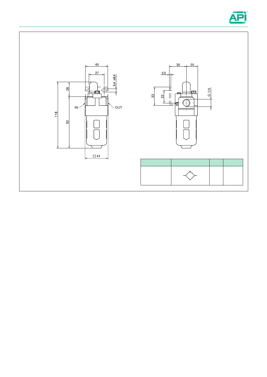
3.2.4

Airline equipment

1/4”

Version

Symbol

Code

Item

Lubricator

090104

A14L
3

3.2.10

Airline equipment

3/8”

Series of modular units with the following standard features :
- Regulators with relieving valve
- Filters standard with 25µ cartridge
- Filters with semi-automatic condense drain
- Cup with protection

The gauges are to be ordered separately; for gauges see from 
page 3.50.1

For mounting accessories, assembling kits and spare parts see 
from page 3.5.1

How to order: A38F5SA

Standard executions

Version

Symbol

Code

Item

Filter-
regulator 
+ lubricator

090105

A38FRRL

Filter-
regulator

090106

A38FRR

Filter

090107

A38F

Regulator

090108

A38R

Lubricator

090109

A38L

Technical data

Fluid

Compressed air

Maximum pressure

10 bar

Regulation range

0,5 ÷ 8,5 bar

Flow at 6 bar (Nl/min)

A38FRRL = 1700; A38FRR = 2000; A38F = 1500; A38R = 2500; A38L = 1700

Temperature range

0 ÷ 60 °C

Suggested oil

With ISO VG 32 viscosity conforming to ISO 3448 standards

Cup capacity

Filter : 20 cm

3

    Lubricator : 50 cm

3

Filtering element

Standard 25 µ - On request 5 µ

Condense drain

Standard semi-automatic - On request automatic

Materials

Body and cup protection: 

Painted aluminium

Regulation group: 

Plastic

Condense drain 

Nickel plated brass

Filtering element 

Sintered bronze

Diaphragm 

Nitrile rubber (NBR)

Cup and sight glass 

Polycarbonate

Springs Steel

Options 

Suffix

Filter 5 µ cartridge

5

Automatic condense drain for filters

SA

Metal cup

TM

With regulation range 0,5÷4 bar

04

A38F

5

SA

Version

Option

Option

3.2.11

Airline equipment

3/8”

Version

Symbol

Code

Item

Filter-regulator

090106

A38FRR

Version

Symbol

Code

Item

Filter-regulator 

+

lubricator

090105 A38FRRL

3

3.2.12

Airline equipment

3/8”

Version

Symbol

Code

Item

Regulator

090108

A38R

Version

Symbol

Code

Item

Filter

090107

A38F

3.2.13

Airline equipment

3/8”

Version

Symbol

Code

Item

Lubricator

090109

A38L

3

3.2.20

Airline equipment

1/2”

Series of modular units with the following standard features :
- Regulators with relieving valve
- Filters standard with 25µ cartridge
- Filters with semi-automatic condense drain
- Cup with protection

The gauges are to be ordered separately; for gauges see from 
page 3.50.1

For mounting accessories, assembling kits and spare parts see 
from page 3.5.1

How to order: A12FRR04SA

Standard executions

Version

Symbol

Code

Item

Filter-
regulator 
+ lubricator

090110

A12FRRL

Filter-
regulator

090111

A12FRR

Filter

090112

A12F

Regulator

090113

A12R

Lubricator

090114

A12L

Technical data

Fluid

Compressed air

Maximum pressure

10 bar

Regulation range

0,5 ÷ 8,5 bar

Flow at 6 bar (Nl/min)

A12FRRL = 3000; A12FRR = 4000; A12F = 4000; A12R = 6000; A12L = 5000

Temperature range

0 ÷ 60 °C

Suggested oil

With ISO VG 32 viscosity conforming to ISO 3448 standards

Cup capacity

Filter : 45 cm

3

    Lubricator : 130 cm

3

Filtering element

Standard 25 µ - On request 5 µ

Condense drain

Standard semi-automatic - On request automatic

Materials

Body and cup protection: 

Painted aluminium

Regulation group: 

Plastic

Condense drain 

Nickel plated brass

Filtering element 

Sintered bronze

Diaphragm 

Nitrile rubber (NBR)

Cup and sight glass 

Polycarbonate

Springs Steel

Options 

Suffix

Filter 5 µ cartridge

5

Automatic condense drain for filters

SA

Metal cup

TM

With regulation range 0,5÷4 bar

04

A12FRR

04

SA

Version

Option

Option

3.2.21

Airline equipment

1/2”

Version

Symbol

Code

Item

Filter-regulator

090111

A12FRR

Version

Symbol

Code

Item

Filter-regulator 

+

lubricator

090110 A12FRRL

3

3.2.22

Airline equipment

1/2”

Version

Symbol

Code

Item

Regulator

090113

A12R

Version

Symbol

Code

Item

Filter

090112

A12F

3.2.23

Airline equipment

1/2”

Version

Symbol

Code

Item

Lubricator

090114

A12L

3

3.2.30

Airline equipment

1”

Series of modular units with the following standard features :
- Regulators with relieving valve
- Filters standard with 25µ cartridge
- Filters with semi-automatic condense drain
- Cup with protection

The gauges are to be ordered separately; for gauges see from 
page 3.50.1

For mounting accessories, assembling kits and spare parts see 
from page 3.5.1

How to order: A01FTMSA

Standard executions

Version

Symbol

Code

Item

Filter-
regulator 
+ lubricator

090115

A01FRRL

Filter-
regulator

090116

A01FRR

Filter

090117

A01F

Regulator

090118

A01R

Lubricator

090119

A01L

Technical data

Fluid

Compressed air

Maximum pressure

10 bar

Regulation range

0,5 ÷ 8,5 bar

Flow at 6 bar (Nl/min)

A01FRRL = 4000; A101FRR = 5500; A01F = 7000; A01R = 8000; A01L = 7000

Temperature range

0 ÷ 60 °C

Suggested oil

With ISO VG 32 viscosity conforming to ISO 3448 standards

Cup capacity

Filter : 130 cm

3

    Lubricator : 130 cm

3

Filtering element

Standard 25 µ - On request 5 µ

Condense drain

Standard semi-automatic - On request automatic

Materials

Body and cup protection: 

Painted aluminium

Regulation group: 

Plastic

Condense drain 

Nickel plated brass

Filtering element 

Sintered bronze

Diaphragm 

Nitrile rubber (NBR)

Cup and sight glass 

Polycarbonate

Springs Steel

Options 

Suffix

Filter 5 µ cartridge

5

Automatic condense drain for filters

SA

Metal cup

TM

With regulation range 0,5÷4 bar

04

A01F

TM

SA

Version

Option

Option

3.2.31

Airline equipment

1”

Version

Symbol

Code

Item

Filter-regulator

090116

A01FRR

Version

Symbol

Code

Item

Filter-regulator 

+

lubricator

090115 A01FRRL

3

3.2.32

Airline equipment

1”

Version

Symbol

Code

Item

Regulator

090118

A01R

Version

Symbol

Code

Item

Filter

090117

A01F

3.2.33

Airline equipment

1”

Version

Symbol

Code

Item

Lubricator

090119

A01L

3

Airline equipment

Modular soft-start valve

Standard executions

Version

Symbol

Type

Item

Electric 1/4

2

1(P)

2(A)

3(R)

1

090231

AVP14E

Electric 3/8

090232

AVP38E

Electric 1/2

090233

AVP12E

Pneumatic 1/4

2

1(P)

2(A)

3(R)

1

090247

AVP14P

Pneumatic 3/8

090248

AVP38P

Pneumatic 1/2

090249

AVP12P

Technical data

Fluid

Compressed air

Maximum pressure

15 bar

Regulation range

0,2 ÷ 10 bar

Temperature range

0 ÷ 60 °C

Size

1/4"

3/8"

1/2"

Section

1 (P) 

 2(A) 20 mm

2

37 mm

2

61 mm

2

2 (A) 

 3(R) 24 mm

2

49 mm

2

76 mm

2

Gauges mountings

1/8"

1/8"

1/8"

Manual Override

Spring return

Materials

Body: 

Painted aluminium

Cover 

Painted aluminium

End cover 

Painted aluminium

Piston guide 

POM / NBR

Seals NBR

Internal parts 

Brass / NBR

Springs 

Stainless steel

3.3.1

Soft/start valve, for progressive pressurizing the pneumatic lines 
when switch on.
Is indicated as safety valve, to quickly exhaust the downstream 
circuit.
- Manual override;
- Exhausting function;
- Low consumption;
- Modular assembly with airline equipment.

For airline equipment see page 3.2.1
For coils type ASA12... see page 2.200.1
For connector type A122... see page 2.210.20
Pressure gauges to be ordered separately, see page 3.50.1
For accessories, assembly kits and spare parts see page 3.5.1

3.3.2

Airline equipment

Modular soft-start valve 

Working principles

1(P)

2(A)

3(R)

B

B

B-B

Pressure “A” ( bar )

Pressure in the start-up phase of the valve


0.5

0.1

0.2

0.3

0.4

0.6

0.1

0.2

0.3

0.4

0.5

0.7

0.8

0.9

1.0

Pressure “P” ( bar )

0

(P : 5 bar)

0

200

400

600

800

1000

1200

1400

0

1

2

3

4

5

AVP12E

AVP38E

AVP14E

Flow rates related to the number of turns of the needle – P = 5 bar

Flow l/min

(P : 5 bar)

N of turns of the regulation needle

OPERATING CONDITIONS

Start-up phase

By actuating electro-pilot or pneumatic-pilot 

 ( or the manual override ), piloting air will push the poppet 

 down opening this way the main 

power valve and at the same time, closing the exhaust 

.

Air from inlet 

 will go through the regulation needle 

 and out to 

A

.

Switching and working phase

In the moment the pressure difference between 

 and 

A

 is P(A) ≥ ½ P(P) the poppet 

 fully open and outlet pressure 

A

 rapidly increase 

until equalize inlet one at 

.

Soft-start valve will not represent any obstacle for the air-flow going through it.

Closing and exhausting phase

By deactivating electro-pilot  or pneumatic pilot 

 ( or the manual override ), the poppet 

 will reposition stopping the air from inlet 

 and 

contemporary exhaust the downstream air in the circuit from 

.

3

3.3.3

G1/8

Manual
Override

B

A

G

F

C

Q

H

E

D

A

R

P

M

T

T

Airline equipment

Modular soft-start valve 

Standard dimensions

Code

Item

Size

A

B

C

D

E

G

H

F

Q

M

T

090231

AVP14E

1/4

66

114

31

22

40

38

0

29

23,5

M4

1/4”

090232

AVP38E

3/8

76

131

36

24

48

43

2

28

27,5

M5

3/8”

090233

AVP12E

1/2

98

146

47

32

52

57

3

42

42

M6

1/2”

G1/8

B

A

G

F

C

Q

H

E

D

A

R

P

G1/8

M

T

T

Code

Item

Size

A

B

C

D

E

G

H

F

Q

M

T

090247

AVP14P

1/4

66

75

31

22

40

38

0

29

23,5

M4

1/4”

090248

AVP38P

3/8

76

84

36

24

48

43

2

28

27,5

M5

3/8”

090249

AVP12P

1/2

98

90

47

32

52

57

3

42

42

M6

1/2”


Content      ..     23      24      25      26     ..