Api Pneumatic. GENERAL CATALOG (2019) - page 19
 

  Index      Manuals     Api Pneumatic. GENERAL CATALOG (2019)


Search            copyright infringement  


Content      ..     17      18      19      20     ..


Api Pneumatic. GENERAL CATALOG (2019) - page 19


2

2.110.1

Valves ISO 5599/1

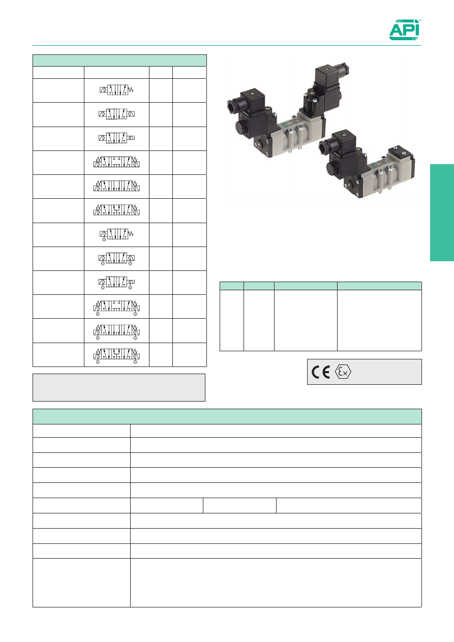
ISO 1, 5/2 - 5/3, electrically operated, with CNOMO pilot

NOTE: FOR VALVES WITH PILOT IN
 

LINE SEE PAGE 2.111.1

Series of spool valves, conforming to ISO 5599/1 standards for the 
mounting only on sub-base, with CNOMO pilot.
Coils and connectors have to be ordered separately.
For the coils type ASA12.../ASA2... 

see page 2.200.1

For the connectors type A122... /A182... 

see page 2.210.20

For the sub-bases type SBA1... 

see page 2.120.1

Code key

Standard executions

Version

Symbol

Code 

Item

5/2

solenoid/spring

14

4 2

5 3

1

032020

ISO1E50

5/2

solenoid/solenoid

12

14

4 2

5 3

1

032030

ISO1E51

5/2

solenoid/solenoid

differential

12

14

4 2

5 3

1

032037

ISO1E52

5/3 with

closed centres

12

14

4 2

5 3

1

032031

ISO1E70

5/3 with

open centres

12

14

4 2

5 3

1

032032

ISO1E71

5/3 with

pressurised

centres

12

14

4 2

5 3

1

032043

ISO1E72

5/2 

solenoid/spring

external air pilot

14

4 2

5 3

1

032021

ISO1K50

5/2 

solenoid/solenoid

external air pilot

12

14

4 2

5 3

1

032044

ISO1K51

5/2 solenoid/solenoid

differential

external air pilot

12

14

4 2

5 3

1

032048

ISO1K52

5/3 with

closed centres

external air pilot

12

14

4 2

5 3

1

032049

ISO1K70

5/3 with

open centres

external air pilot

12

14

4 2

5 3

1

032053

ISO1K71

5/3 with

pressurised centres

external air pilot

12

14

4 2

5 3

1

032054

ISO1K72

Series 

Size

Actuation

Function

ISO

1
2

E = electrical

K = electrical


 with  external 

air pilot

50 = 5/2 solenoid/spring

51 = 5/2 solenoid/solenoid

52 =  5/2 solenoid/solenoid 

differential

70 = 5/3 CC

71 = 5/3 OC
72 = 5/3 PC

On request, they can be supplied 

according to 2014/34/EU - 

ATEX

II 2Gc IIB T5
II 2Dc T100°C

Technical data

Fluid

Compressed filtered air with or without lubrication. Lubrication, if started, must be continued.

Pressure range

0 ÷ 10 bar

Temperature range

-10°C ÷ +60°C

Orifice

8,5 mm

Flow

1100 Nl/min at 6 bar with ∆P 1 bar

Minimum piloting pressure

Spring return: 2 bar

Bistable: 1 bar

3 positions: 2,5 bar

Mounting

In any position

Electropilot

Conforming to CNOMO

Manual override

Bistable on solenoid pilot - Spring return on valve body

Materials

Body: 

Die-cast painted aluminium

Covers: PBT

Spool: 

Hard aluminium anodized

Distancers: Aluminium

Seals: 

Hydrogenated Nitrile Butadiene Rubber (HNBR)

2.110.2

Valves ISO 5599/1

ISO 1, 5/2 - 5/3, electrically operated, with CNOMO pilot

140

112,5

M5

40

71

Ch.4

M5

8,

5

54

44

112,5

M5

40

71

Ch.4

M5

8,

5

54

170

Version

Symbol

Code 

Item

5/2 solenoid/

spring

14

4 2

5 3

1

032020

ISO1E50

5/2 solenoid/

spring,

external air pilot

14

4 2

5 3

1

032021

ISO1K50

Version

Symbol

Code 

Item

5/2

solenoid/solenoid

12

14

4 2

5 3

1

032030 ISO1E51

5/2

solenoid/solenoid

differential

12

14

4 2

5 3

1

032037 ISO1E52

5/3 with

closed centres

12

14

4 2

5 3

1

032031 ISO1E70

5/3 with

open centres

12

14

4 2

5 3

1

032032 ISO1E71

5/3 with

pressurised 

centres

12

14

4 2

5 3

1

032043 ISO1E72

5/2

solenoid/solenoid

external air pilot

12

14

4 2

5 3

1

032044 ISO1K51

5/2 solenoid/

solenoid external

air pilot differential

12

14

4 2

5 3

1

032048 ISO1K52

5/3 with

closed centres

external air pilot

12

14

4 2

5 3

1

032049 ISO1K70

5/3 with

open centres

external air pilot

12

14

4 2

5 3

1

032053 ISO1K71

5/3 with 

pressurised 

centres 

external air pilot

12

14

4 2

5 3

1

032054 ISO1K72

2

2.111.1

Valves ISO 5599/1

ISO 1, 5/2 - 5/3, electrically operated, with IN LINE pilot

NOTE: FOR VALVES WITH CNOMO
 

PILOT SEE PAGE 2.110.1

Series of spool valves, conforming to ISO 5599/1 standards for the 
mounting only on sub-base, with IN LINE pilot.
Coils and connectors have to be ordered separately.
For the coils type ASA12.../ASA2... 

see page 2.200.1

For the connectors type A122... /A182... 

see page 2.210.20

For the sub-bases type SBA1... 

see page 2.120.1

Code key

Standard executions

Version

Symbol

Code 

Item

5/2

solenoid/spring

14

4 2

5 3

1

032060 ISO1EL50

5/2

solenoid/solenoid

12

14

4 2

5 3

1

032070 ISO1EL51

5/2

solenoid/solenoid

differential

12

14

4 2

5 3

1

032061 ISO1EL52

5/3 with

closed centres

12

14

4 2

5 3

1

032071 ISO1EL70

5/3 with

open centres

12

14

4 2

5 3

1

032072 ISO1EL71

5/3 with

pressurised

centres

12

14

4 2

5 3

1

032066 ISO1EL72

5/2 

solenoid/spring

external air pilot

14

4 2

5 3

1

032063 ISO1KL50

5/2 

solenoid/solenoid

external air pilot

12

14

4 2

5 3

1

032064 ISO1KL51

5/2 solenoid/solenoid

differential

external air pilot

12

14

4 2

5 3

1

032065 ISO1KL52

5/3 with

closed centres

external air pilot

12

14

4 2

5 3

1

032067 ISO1KL70

5/3 with

open centres

external air pilot

12

14

4 2

5 3

1

032068 ISO1KL71

5/3 with

pressurised centres

external air pilot

12

14

4 2

5 3

1

032069 ISO1KL72

Series 

Size

Actuation

Function

ISO

1
2

EL =  electrical

KL  =   electrical 

with external 

air pilot

50 = 5/2 solenoid/spring

51 = 5/2 solenoid/solenoid

52 =  5/2 solenoid/solenoid  

differential

70 = 5/3 CC

71 = 5/3 OC
72 = 5/3 PC

On request, they can be supplied 

according to 2014/34/EU - 

ATEX

II 2Gc IIB T5
II 2Dc T100°C

Technical data

Fluid

Compressed filtered air with or without lubrication. Lubrication, if started, must be continued.

Pressure range

0 ÷ 10 bar

Temperature range

-10°C ÷ +60°C

Orifice

8,5 mm

Flow

1100 Nl/min at 6 bar with ∆P 1 bar

Minimum piloting pressure

Spring return: 2 bar

Bistable: 1 bar

3 positions: 2,5 bar

Mounting

In any position

Electropilot

IN LINE

Manual override

Bistable on solenoid pilot - Spring return on valve body

Materials

Body: 

Die-cast painted aluminium

Covers: PBT

Spool: 

Hard aluminium anodized

Distancers: Aluminium

Seals: 

Hydrogenated Nitrile Butadiene Rubber (HNBR)

2.111.2

Valves ISO 5599/1

ISO 1, 5/2 - 5/3, electrically operated, with IN LINE pilot

159

127

M5

40

44

Ch.4

13

M5

8,

5

207

141,5

M5

40

44

Ch.4

13

M5

8,

5

Version

Symbol

Code 

Item

5/2 solenoid/

spring

14

4 2

5 3

1

032060 ISO1EL50

5/2 solenoid/

spring,

external air pilot

14

4 2

5 3

1

032063 ISO1KL50

Version

Symbol

Code 

Item

5/2

solenoid/solenoid

12

14

4 2

5 3

1

032070 ISO1EL51

5/2

solenoid/solenoid

differential

12

14

4 2

5 3

1

032061 ISO1EL52

5/3 with

closed centres

12

14

4 2

5 3

1

032071 ISO1EL70

5/3 with

open centres

12

14

4 2

5 3

1

032072 ISO1EL71

5/3 with

pressurised 

centres

12

14

4 2

5 3

1

032066 ISO1EL72

5/2

solenoid/solenoid

external air pilot

12

14

4 2

5 3

1

032064 ISO1KL51

5/2 solenoid/

solenoid external

air pilot differential

12

14

4 2

5 3

1

032065 ISO1KL52

5/3 with

closed centres

external air pilot

12

14

4 2

5 3

1

032067 ISO1KL70

5/3 with

open centres

external air pilot

12

14

4 2

5 3

1

032068 ISO1KL71

5/3 with pressur-

ised centres 

external air pilot

12

14

4 2

5 3

1

032069 ISO1KL72

2

2.113.1

Valves ISO 5599/1

ISO1, 5/2 - 5/3, pneumatically operated

Standard executions

Version

Symbol

Code

Item 

5/2 pilot/spring

14

4 2

5 3

1

032000

ISO1P50

5/2

pilot/pilot

12

14

4 2

5 3

1

032001

ISO1P51

5/2 

pilot/pilot

differential

12

14

4 2

5 3

1

032002

ISO1P52

5/3 with

closed centres

12

14

4 2

5 3

1

032003

ISO1P70

5/3 with

open centres

12

14

4 2

5 3

1

032004

ISO1P71

5/3

with pressurised

centres

12

14

4 2

5 3

1

032019

ISO1P72

Code key

Series of spool valves, conforming to ISO 5599/1 standards for the 
mounting only on sub-base.
For the sub-bases type SBA1... 

see page 2.120.1

Series 

Size

Actuation

Function

ISO

1
2

P = pneumatic

50 = 5/2 pilot/spring

51 = 5/2 pilot/pilot

52 =  5/2 pilot/pilot 

differential

70 = 5/3 CC

71 = 5/3 OC
72 = 5/3 PC

On request, they can be supplied 

according to 2014/34/EU - 

ATEX

II 2Gc IIB T5
II 2Dc T100°C

Technical data

Fluid

Compressed filtered air with or without lubrication. Lubrication, if started, must be continued.

Pressure range

0 ÷ 10 bar

Temperature range

-10°C ÷ +60°C

Orifice

8,5 mm

Flow

1100 Nl/min at 6 bar with ∆P 1 bar

Minimum piloting pressure

Spring return: 2 bar

Bistable: 1 bar

3 positions: 2,5 bar

Mounting

In any position

Manual override

Spring return on valve body

Materials

Body: 

Die-cast painted aluminium

Covers: PBT

Spool: 

Hard aluminium anodized

Distancers: Aluminium

Seals: 

Hydrogenated Nitrile Butadiene Rubber (HNBR)

2.113.2

Valves ISO 5599/1

ISO1, 5/2 - 5/3, pneumatically operated

112,5

M5

40

44

Ch.4

8,

5

Version

Symbol

Code 

Item

5/2 

pilot/spring

14

4 2

5 3

1

032000

ISO1P50

5/2

pilot/pilot

12

14

4 2

5 3

1

032001

ISO1P51

5/2 

pilot/pilot

differential

12

14

4 2

5 3

1

032002

ISO1P52

5/3 with

closed centres

12

14

4 2

5 3

1

032003

ISO1P70

5/3 with

open centres

12

14

4 2

5 3

1

032004

ISO1P71

5/3

with pressurised

centres

12

14

4 2

5 3

1

032019

ISO1P72

2

2.120.1

Valves ISO 5599/1

Sub-bases, ISO1

The blanck manifold end plate can be used to separate 
2 supplies with different pressures on the same manifold.

The kit SBA1M includes:  2 screws and 3 seals
The kit SBA1C/A includes: 2 screws and 3 seals
The kit SBA1T includes: 

4 screws and 1 seal

The kit SBA1A2 includes:  4 screws and 6 seals

M5

Type:  

SBA1S

Type:  

SBA1M

Type:  

SBA1A2

Type:  

SBA1C

 SBA1A

Series of single and manifold sub-bases for valves ISO5599/1 
size 1.

On request, they can be supplied 

according to 2014/34/EU - 

ATEX

II 2Gc IIB T5
II 2Dc T100°C

Standard executions

Version

Symbol

Code

Item

Single sub-base

032190

SBA1S

Manifold 
sub-base

032120

SBA1M

Blank manifold 
end plate

032140

SBA1C

Ported manifold 
end plate

032141

SBA1A

Manifold blanking 
plate

032170

SBA1T

Interface for 
sub-base from size 
ISO1 to ISO2

032160

SBA1A2

Materials:

Body: Die-cast aluminium 

Seals: Nitrile rubber (NBR) 

Screws: Zinc plated steel

A

B

C

D

E

F

G

H

56

82,5

36

28

18

24

1/4”

92,5

A

B

C

D

E

F

G

H

I

J

K

28

M5

4,5

36

8,5

9

1/4”

92

43

1/4” 106

A

B

C

D

E

F

G

92

106

22

36

8

5,5

1/4”

2.130.1

Valves ISO 5599/1

ISO2, 5/2 - 5/3, electrically operated, with CNOMO pilot

Series of spool valves, conforming to ISO 5599/1 standards for the 
mounting only on sub-base, with CNOMO pilot.
Coils and connectors have to be ordered separately.
For the coils type ASA12.../ASA2... 

see page 2.200.1

For the connectors type A122... /A182... 

see page 2.210.20

For the sub-bases type SBA2... 

see page 2.137.1

Code key

Standard executions

Version

Symbol

Code 

Item

5/2

solenoid/spring

14

4 2

5 3

1

032040

ISO2E50

5/2

solenoid/solenoid

12

14

4 2

5 3

1

032050

ISO2E51

5/2

solenoid/solenoid

differential

12

14

4 2

5 3

1

032042

ISO2E52

5/3 with

closed centres

12

14

4 2

5 3

1

032051

ISO2E70

5/3 with

open centres

12

14

4 2

5 3

1

032052

ISO2E71

5/3 with

pressurised

centres

12

14

4 2

5 3

1

032055

ISO2E72

5/2 

solenoid/spring

external air pilot

14

4 2

5 3

1

032039

ISO2K50

5/2 

solenoid/solenoid

external air pilot

12

14

4 2

5 3

1

032056

ISO2K51

5/2 solenoid/solenoid

differential

external air pilot

12

14

4 2

5 3

1

032057

ISO2K52

5/3 with

closed centres

external air pilot

12

14

4 2

5 3

1

032058

ISO2K70

5/3 with

open centres

external air pilot

12

14

4 2

5 3

1

032059

ISO2K71

5/3 with

pressurised centres

external air pilot

12

14

4 2

5 3

1

032062

ISO2K72

Series 

Size

Actuation

Function

ISO

1
2

E = electrical

K  =   electrical 

with external 

air pilot

50 = 5/2 solenoid/spring

51 = 5/2 solenoid/solenoid

52 =  5/2 solenoid/solenoid 

differential

70 = 5/3 CC

71 = 5/3 OC
72 = 5/3 PC

On request, they can be supplied 

according to 2014/34/EU - 

ATEX

II 2Gc IIB T5
II 2Dc T100°C

Technical data

Fluid

Compressed filtered air with or without lubrication. Lubrication, if started, must be continued.

Pressure range

0 ÷ 10 bar

Temperature range

-10°C ÷ +60°C

Orifice

15 mm

Flow

2900 Nl/min at 6 bar with ∆P 1 bar

Minimum piloting pressure

Spring return: 2 bar

Bistable: 1 bar

3 positions: 2,5 bar

Mounting

In any position

Electropilot

Conforming to CNOMO

Manual override

Bistable on solenoid pilot - Spring return on valve body

Materials

Body: 

Die-cast painted aluminium

Covers: PBT

Spool: 

Hard aluminium anodized

Distancers: Aluminium

Seals: 

Hydrogenated Nitrile Butadiene Rubber (HNBR)

2

2.130.2

Valves ISO 5599/1

ISO2, 5/2 - 5/3, electrically operated, with CNOMO pilot

166

154

M6

52

83

M5

8

66

56

Ch.5

154

M6

52

Ch.5

M5

8

66

180

83

Version

Symbol

Code 

Item

5/2 solenoid/

spring

14

4 2

5 3

1

032040

ISO2E50

5/2 solenoid/

spring,

external air pilot

14

4 2

5 3

1

032039

ISO2K50

Version

Symbol

Code 

Item

5/2 solenoid/

solenoid

12

14

4 2

5 3

1

032050 ISO2E51

5/2 solenoid/

solenoid

differential

12

14

4 2

5 3

1

032042 ISO2E52

5/3 with closed 

centres

12

14

4 2

5 3

1

032051 ISO2E70

5/3 with open 

centres

12

14

4 2

5 3

1

032052 ISO2E71

5/3 with

pressurised 

centres

12

14

4 2

5 3

1

032055 ISO2E72

5/2 solenoid/

solenoid

external air pilot

12

14

4 2

5 3

1

032056 ISO2K51

5/2 solenoid/

solenoid

external air pilot

differential

12

14

4 2

5 3

1

032057 ISO2K52

5/3 with closed 

centres,

external air pilot

12

14

4 2

5 3

1

032058 ISO2K70

5/3 with open 

centres,

external air pilot

12

14

4 2

5 3

1

032059 ISO2K71

5/3 with 

pressurised centres

external air pilot

12

14

4 2

5 3

1

032062 ISO2K72

2.133.1

Valves ISO 5599/1

ISO2, 5/2 - 5/3, pneumatically operated

Standard executions

Version

Symbol

Code

Item 

5/2 pilot/spring

14

4 2

5 3

1

032005

ISO2P50

5/2

pilot/pilot

12

14

4 2

5 3

1

032011

ISO2P51

5/2 

pilot/pilot

differential

12

14

4 2

5 3

1

032012

ISO2P52

5/3 with

closed centres

12

14

4 2

5 3

1

032013

ISO2P70

5/3 with

open centres

12

14

4 2

5 3

1

032014

ISO2P71

5/3

with pressurised

centres

12

14

4 2

5 3

1

032038

ISO2P72

Code key

Series of spool valves, conforming to ISO 5599/1 standards for the 
mounting only on sub-base.
For the sub-bases type SBA2... 

see page 2.137.1

Series 

Size

Actuation

Function

ISO

1
2

P = pneumatic

50 = 5/2 pilot/spring

51 = 5/2 pilot/pilot

52 = 5/2 pilot/pilot 

 differential

70 = 5/3 CC

71 = 5/3 OC
72 = 5/3 PC

On request, they can be supplied 

according to 2014/34/EU - 

ATEX

II 2Gc IIB T5
II 2Dc T100°C

Technical data

Fluid

Compressed filtered air with or without lubrication. Lubrication, if started, must be continued.

Pressure range

0 ÷ 10 bar

Temperature range

-10°C ÷ +60°C

Orifice

15 mm

Flow

2900 Nl/min at 6 bar with ∆P 1 bar

Minimum piloting pressure

Spring return: 2 bar

Bistable: 1 bar

3 positions: 2,5 bar

Mounting

In any position

Manual override

Spring return on valve body

Materials

Body: 

Die-cast painted aluminium

Covers: PBT

Spool: 

Hard aluminium anodized

Distancers: Aluminium

Seals: 

Hydrogenated Nitrile Butadiene Rubber (HNBR)

2

2.133.2

Valves ISO 5599/1

ISO2, 5/2 - 5/3, pneumatically operated

154

M6

52

56

8

Ch.5

Version

Symbol

Code 

Item

5/2 pilot/spring

14

4 2

5 3

1

032005

ISO2P50

5/2

pilot/pilot

12

14

4 2

5 3

1

032011

ISO2P51

5/2 

pilot/pilot

differential

12

14

4 2

5 3

1

032012

ISO2P52

5/3 with

closed centres

12

14

4 2

5 3

1

032013

ISO2P70

5/3 with

open centres

12

14

4 2

5 3

1

032014

ISO2P71

5/3

with pressurised

centres

12

14

4 2

5 3

1

032038

ISO2P72

2.137.1

Valves ISO 5599/1

Sub-bases, ISO2

The blank manifold end plate can be used to separate 2 
supplies with different pressures on the same manifold.

The kit SBA2M includes: 

2 screws and 3 seals

The kit SBA2C/A includes:  2 screws and 3 seals
The kit SBA2T includes: 

4 screws and 1 seal

The kit SBA1A2 includes: 

4 screws and 6 seals

M5

Type:  

SBA2S

Type:  

SBA2M

Type:  

SBA1A2

Type:  

SBA2C

 SBA2A

Series of single and manifold sub-bases for valves ISO5599/1 
size 2.

On request, they can be supplied 

according to 2014/34/EU - 

ATEX

II 2Gc IIB T5
II 2Dc T100°C

Standard executions

Version

Symbol

Code

Item 

Single sub-base

032200

SBA2S

Manifold sub-base

032130

SBA2M

Blank manifold end 
plate

032150

SBA2C

Ported manifold end 
plate

032151

SBA2A

Manifold blanking 
plate

032180

SBA2T

Interface for sub-base 
from size ISO1 to 
ISO2

032160

SBA1A2

Materials:

Body: Die-cast aluminium 

Seals: Nitrile rubber (NBR) 

Screws: Zinc plated steel

A

B

C

D

E

F

G

H

65

100,5

48

38

24

30

3/8”

112,5

A

B

C

D

E

F

G

H

I

J

K

38

M6

7

48

10

12

3/8”

102

56

3/8” 120

A

B

C

D

E

F

G

102

120

29

43

7

6,5

1/4”

2

2.165.1

Indirectly operated solenoid valves for water and steam

2/2, normally closed from 1/4” to 2”

Series of indirectly operated valves for fluids and compressed 
air, servoassisted with diaphragm.
Coils and connectors have to be ordered separately.

For the coils type ASA33/ASA32 

see from page 2.200.20.

For the connectors type A122/A182 see page 2.210.20/2.210.30.

How to order: AEN22100N

For order codes see the table below.

Standard executions

Version

Symbol

Type

With NBR seals 
(-10°C ÷ + 90°C)

AEN22

With FKM seals 
(-10°C ÷ +130°C)

AEV22

With EPDM seals 
(+140°C)

AEP22

Connections

1/4” = 014

1” = 100

3/8” = 038

1 1/4” = 114

1/2” = 012

1 1/2

” 

= 112

3/4” = 034

2” = 200

Type

Port

Options

AEN22

100

N

Technical data

Fluid

Compressed filtered air with or without lubrication. Lubrication, if started, must be continued.

Pressure range

25 bar

Fluid maximum viscosity

25 cSt (mm

2

/s)

Orifice

See the table below

Flow

See the table below

Mounting

Better with the coil high

Materials

Body: Brass

Seals: 

NBR - FKM - EPDM

Internal parts: 

Stainless steel

Connections

Orifice 

mm

Flow 

m

3

/h

Differential pressure bar

Power

Coil 

type

Order codes

Min

Max

AC 

(VA)

DC 

(Watt)

NBR

(AEN type)

FKM

(AEV type)

EPDM

(AEP type)

AC

DC

Inrush

Rating

1/4”

10

1,5

0,15

15

15

12

8

6,5

ASA33

035501

035511

035521

3/8”

12

2

0,15

15

15

12

8

6,5

ASA33

035502

035512

035522

1/2”

12

2,2

0,15

15

15

12

8

6,5

ASA33

035503

035513

035523

3/4”

18

5,2

0,15

13

13

12

8

6,5

ASA33

035504

035514

035524

1”

24

10,2

0,15

10

10

12

8

6,5

ASA33

035505

035515

035525

1 1/4”

38

18

0,15

10

10

20

15

10

ASA32

035506

035516

035526

1 1/2”

38

21

0,15

10

10

20

15

10

ASA32

035507

035517

035527

2”

50

36

0,15

10

10

20

15

10

ASA32

035508

035518

035528

Options

Suffix

Chemical nickel-plated

N

Normally open

NA

Bistable manual override

M

To identify order codes see the table below.

2.165.2

Indirectly operated solenoid valves for water and steam

2/2, normally closed from 1/4” to 2”

H

a

b

c

d

e

f

g

Weight 

kg.

1/4”

47

64

11

32

16

-

22

0,25

3/8”

60

73

14

45

16

6

22

0,45

1/2”

60

73

14

45

16

6

22

0,40

3/4”

75

75

18

55

20

8,5

22

0,66

1”

96

85

20

72

32

-

22

1,20

1” 1/4

144

95

28

102

45

-

30

3,20

1” 1/2

144

95

28

102

45

-

30

2,90

2”

152

119

35

119

48

-

30

4,50

2

2.170.1

Integrated circuits

Flip-flop 1/4” and continuous cycling 1/8”, 5/2 electric and pneumatic

Series of Flip-flop electrically or pneumatically operated.

Flip-flop: Circuit composed by a 1/4” power valve 5/2 two stable 
position. With the same signal applied twice at different times the 
cylinder carries out a complete cycle.

Coils and connectors have to be ordered separately.
For the coils type ASA12.. 

see page 2.200.1.

For the connectors type A12209.. 

see page 2.210.20.

Series of integrated circuits, electrically or pneumatically 
operated.

Continuous cycling: Circuit composed by a 1/8’’ power valve 5/2 
single stable position. Keeping the signal the cylinder carries out 
continuous cycling till the signal is not interrupted.

Coils and connectors have to be ordered separately.
For the coils type ASA12.. 

see page 2.200.1.

For the connectors type A12209.. 

see page 2.210.20.

Standard executions

Version

Symbol

Code

Item

Electric 
Flip-flop

033170 AEF1520

Pneumatic 
Flip-flop

033160 APF1520

Standard executions

Version

Symbol

Code

Item

Electric 
continuous 
cycling

033172 AEC1520

Pneumatic 
continuous 
cycling

033171 APC1520

Technical data

Fluid

Compressed filtered air with or without lubrication. Lubrication, if started, must be continued.

Pressure range

2,5 

÷

 10 bar (AEF/APF)

2,5 

÷

 8 bar (AEC/APC)

Temperature range

-10°C ÷ +60°C

Orifice

6 mm (AEF/APF)

8 mm (AEC/APC)

Flow

800 Nl/min (AEF/APF)

1200 Nl/min (AEC/APC)

Manual override

Two stable position, flat

Response time

Energising: 20 ms

De-energising: 38 ms

Mounting

In any position

Materials

Body: 

Anodised aluminium

Base: 

Anodised aluminium

Seals: 

Hydrogenated Nitrile Butadiene Rubber (HNBR)

On request, they can be supplied 

according to 2014/34/EU - 

ATEX

II 2Gc IIB T5
II 2Dc T100°C

2.170.2

Integrated circuits

Flip-flop 1/4” and continuous cycling 1/8”, 5/2 electric and pneumatic

G1/4

149

21

37

4,2

25

40

4

59

G1/8

20

45

Type: 

APF1520

4

G1/4

149

59

21

37

4,2

25

33

58

40

Type: 

AEF1520

Type:  

APC1520

Type:  

AEC1520


Content      ..     17      18      19      20     ..