Api Pneumatic. GENERAL CATALOG (2019) - page 17
 

  Index      Manuals     Api Pneumatic. GENERAL CATALOG (2019)


Search            copyright infringement  


Content      ..     15      16      17      18     ..


Api Pneumatic. GENERAL CATALOG (2019) - page 17


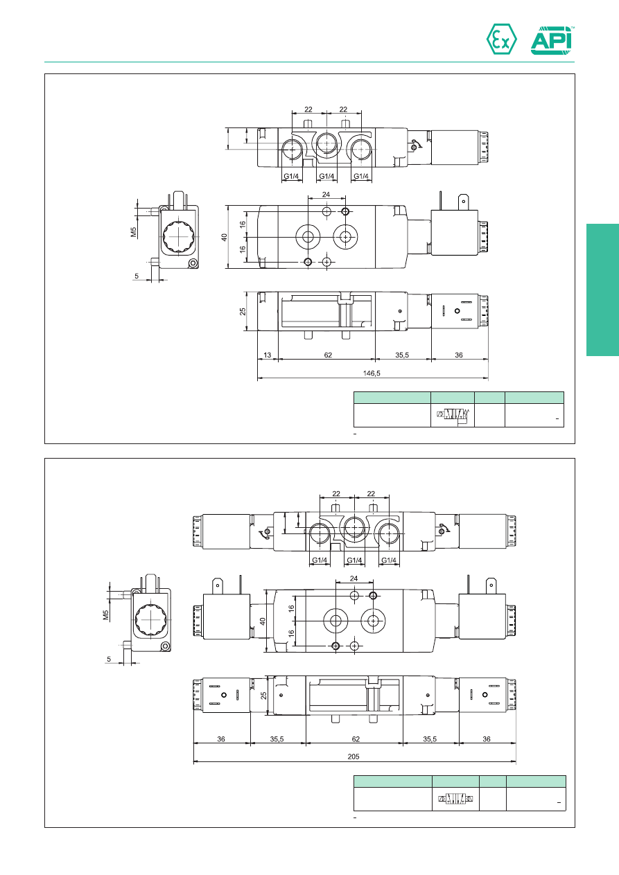
2

2.88.22

10

14

10

14

Valves series A1N - Non-sparking coil Ex nA

1/4”, 3/2 - 5/2, NAMUR interface, electrically operated Ex nA

Version

Symbol

Code

Item

5/2 solenoid/spring

14

5 1 3

12

4 2

A1NE250XX*

* For coil voltage: see code key at page 2.88.20 

Version

Symbol

Code

Item

5/2 solenoid/solenoid

12

14

4

5

2

3

1

A1NE251XX*

* For coil voltage: see code key at page 2.88.20 

2

Valves series A1N - Intrinsic safety Ex ia

1/4”, 3/2 - 5/2, NAMUR interface, electrically operated Ex ia

2.88.40

Technical data

Fluid

Compressed filtered air with or without lubrication. Lubrication, if started, must be continued.

Threaded connection

1/4 Gas 

Pressure range

Spring return: 2 ÷ 7 bar 

Bistable: 2 ÷ 7 bar 

Minimum external air pressure

2 bar 

Temperature range

-10°C ÷ +60°C (XA standard)

-10°C ÷ +50°C (XA1 standard)

-25°C ÷ +60°C (XA BT)

-25°C ÷ +50°C (XA1 BT)

Protection grade

IP 65

Ø Orifice

7 mm

Flow

1.000 Nl/min a 6 bar con ∆P 1 bar

Mounting

In any position (vertical assembly is not recommended for bistable valves subjected to vibration)

Manual override

Bistable

Electrical 
characteristics

Nominal voltage

21.6 ÷ 28 VDC

21.6 ÷ 28 VDC

Max voltage

28 VDC

28 VDC

Nominal current

0.115 A (at 28 VDC)

0.115 A (at 28 VDC)

Nominal power

1.6 W (at 28 VDC)

1.6 W (at 28 VDC)

Duty cycle

100% ED

100% ED

Temp. class

T6

T4

Response time (at 6 bar)

Energising: - ms

Energising: - ms

Energising: - ms

De-energising: - ms

De-energising: - ms

De-energising: - ms

 Materials

B  

Body:

Die-cast painted aluminium

7

1

2

3

6

2

4

5

8

Cover:

Hostaform C 13031

Spool:

Hard aluminium anodized

Distancers:

Ixef 1022

Seals:

Hydrogenate Nitrile Butadine Rubber (HNBR)

Spring:

Stainless steel

Operator:

Brass

Coil:

Thermoset resin

Series of spool valves, with static seals, high flow, for mounting on NAMUR 
interface 

Low consumption solenoid operator, conforming to 2014/34/EU  Directive, 
certified:


II 2G Ex ia IIC T6 Gb


II 2D Ex tb IIIC T80°C Db X IP65


II 2G Ex ia IIC T4 Gb


II 2D Ex tb IIIC T80°C Db X IP65

Coil and connector included.

Code key

Series

Actuation

Size

Function

Hazardous areas

Voltages

Options

A1N = NAMUR

E = electrical Ø9 2 = 1/4 Gas 30 = 3/2 NC

32 = 3/2 solenoid/solenoid
50 = 5/2 solenoid/spring
51 = 5/2 solenoid/solenoid

XA   = II 2G Ex ia IIC T6 Gb

          II 2D Ex tb IIIC T80°C Db X IP65

XA1 = II 2G Ex ia IIC T4 Gb

          II 2D Ex tb IIIC T80°C Db X IP65

C = 24 VDC

BT = low 

temp. seals

Standard executions

Version

Symbol

Code

3/2 NC

14

4

5 1

12

For code key see 

table below

3/2 solenoid/solenoid

12

14

4

5 1

5/2 solenoid/spring

14

5 1 3

12

4 2

5/2 solenoid/solenoid

12

14

4

5

2

3

1

Options

Suffix

Low temperature seals

-25°C ÷ +60°C

BT

-25°C ÷ +50°C

Valves series A1N - Intrinsic safety Ex ia

1/4”, 3/2 - 5/2, NAMUR interface, electrically operated Ex ia

2.88.41

Version

Symbol

Code

Item

3/2 NC

14

4

5 1

12

A1NE230XA*

* For coil voltage: see code key at page 2.88.40 

Version

Symbol

Code

Item

3/2 solenoid/solenoid

12

14

4

5 1

A1NE232XA*

* For coil voltage: see code key at page 2.88.40 

2

Valves series A1N - Intrinsic safety Ex ia

1/4”, 3/2 - 5/2, NAMUR interface, electrically operated Ex ia

2.88.42

Version

Symbol

Code

Item

5/2 solenoid/spring

14

5 1 3

12

4 2

A1NE250XA*

* For coil voltage: see code key at page 2.88.40 

Version

Symbol

Code

Item

5/2 solenoid/solenoid

12

14

4

5

2

3

1

A1NE251XA*

* For coil voltage: see code key at page 2.88.40 

2

Valves series A1N - Encapsulated coil Ex dm

1/4”, 3/2 - 5/2, NAMUR interface, electrically operated Ex dm

Series of spool valves, with static seals, high flow, for mounting on NAMUR 
interface.

Solenoid operator with a special coil for pneumatic application in potentially 
explosive environment (group II). 
The protection is assured by a thermal fuse that, in case of damage, disconnects 
the coil from power.
Solenoid system is conforming to 2014/34/EU Directive, certified: 


II 2G Ex db mb IIC T5 Gb 


II 2D Ex tb IIIC T95°C Db IP66

2.88.60

Code key

Series

Actuation

Size

Function

Hazardous areas

Voltages

Options

A1N = NAMUR

E = electrical Ø9 2 = 1/4 Gas 30 = 3/2 NC

32 = 3/2 solenoid/solenoid
50 = 5/2 solenoid/spring
51 = 5/2 solenoid/solenoid

XB = II 2G Ex db mb IIC T5 Gb

        II 2D Ex tb IIIC T95°C Db IP66 

A =    6 VDC
B =  12 VDC
C =  24 VDC *
D =  48 VDC

E =    12 VAC
F  =    24 VAC
G =    48 VAC
H =  100 VAC
I  =  110 VAC
L  =  115 VAC
M =  120 VAC
O =  220 VAC
P =  230 VAC
Q =  240 VAC

BT = low 

temp. seals

* = Standard voltages

Technical data

Fluid

Compressed filtered air with or without lubrication. Lubrication, if started, must be continued.

Threaded connection

1/4 Gas

Pressure range

Spring return: 1.5 ÷ 10 bar

Bistable: 1 ÷ 10 bar

Minimum external air pressure

1.5 bar 

Temperature range

-10°C ÷ +50°C (standard)

-25°C ÷ +50°C (BT)

Protection grade

IP 66

Ø Orifice

7 mm

Flow

1.000 Nl/min at 6 bar with ∆P 1 bar

Mounting

In any position (vertical assembly is not recommended for bistable valves subjected to vibration)

Manual override

Bistable

Electrical 
characteristics

Nominal voltage

6 VDC

12 VDC

24 VDC

48 VDC

12 VAC

24VAC

48 VAC

100 VAC 110 VAC 115 VAC 120 VAC 220 VAC 230 VAC 240 VAC

Frequency

-

-

-

-

50/60 Hz 50/60 Hz 50/60 Hz 50/60 Hz 50/60 Hz 50/60 Hz 50/60 Hz 50/60 Hz 50/60 Hz 50/60 Hz

Nominal current

0.510 A

0.250 A

0.125 A

0.063 A

0.270 A

0.133 A

0.067 A

0.032 A

0.029 A

0.028 A

0.027 A

0.014 A

0.014 A

0.013 A

Nominal power

3 W

3 W

3 W

3 W

3.2 VA

3.2 VA

3.2 VA

3.2 VA

3.2 VA

3.2 VA

3.2 VA

3.2 VA

3.2 VA

3.2 VA

Duty cycle

100% ED

Temp. class

T5

Response time (at 6 bar)

Energising: - ms

Energising: - ms

Energising: - ms

De-energising: - ms

De-energising: - ms

De-energising: - ms

 Materials

B  

Body:

Die-cast painted aluminium

7

1

2

3

6

2

4

5

8

Cover:

Hostaform C 13031

Spool:

Hard aluminium anodized

Distancers:

Ixef 1022

Seals:

Hydrogenate Nitrile Butadine Rubber (HNBR)

Spring:

Stainless steel

Operator:

Brass

Coil:

Thermoset  resin

Standard executions

Version

Symbol

Code

3/2 NC

14

4

5 1

12

For code key see 

table below

3/2 solenoid/solenoid

12

14

4

5 1

5/2 solenoid/spring

14

5 1 3

12

4 2

5/2 solenoid/solenoid

12

14

4

5

2

3

1

Options

Suffix

Low temperature seals

-25°C ÷ +50°C

BT

82

82

2.88.61

Valves series A1N - Encapsulated coil Ex dm

1/4”, 3/2 - 5/2, NAMUR interface, electrically operated Ex dm

Version

Symbol

Code

Item

3/2 NC

14

4

5 1

12

A1NE230XB*

* For coil voltage: see code key at page 2.88.60 

Version

Symbol

Code

Item

3/2 solenoid/solenoid

12

14

4

5 1

A1NE232XB*

* For coil voltage: see code key at page 2.88.60 

2

82

82

2.88.62

Valves series A1N - Encapsulated coil Ex dm

1/4”, 3/2 - 5/2, NAMUR interface, electrically operated Ex dm

Version

Symbol

Code

Item

5/2 solenoid/spring

14

5 1 3

12

4 2

A1NE250XB*

* For coil voltage: see code key at page 2.88.60 

Version

Symbol

Code

Item

5/2 solenoid/solenoid

12

14

4

5

2

3

1

A1NE251XB*

* For coil voltage: see code key at page 2.88.60 

2

2.88.80

Valves series A1N - Flameproof coil Ex db

1/4”, 3/2 - 5/2, NAMUR interface, electrically operated Ex db

Series of spool valves, with static seals, high flow, for mounting on NAMUR 
interface 

Flameproof solenoid operator is used extensively to prevent possible 
overheating or sparking of electrical equipment causing ignition in  potentially 
explosive atmosphere.

Flameproof solenoid coil is enclused in a robust enclosure which will contain 
an internal explosion should it occur and prevent its transmission to the 
surrounding atmosphere.

All construction joints in the enclosure are known as flame paths which prevent 
the transmission of a flame from the enclosure to the outside atmosphere. 


II 2G Ex db IIC T6 Gb

Technical data

Fluid

Compressed filtered air with or without lubrication. Lubrication, if started, must be continued.

Threaded connection

1/4 Gas

Pressure range

Spring return: 2 ÷ 8 bar

Bistable: 2 ÷ 8 bar

Temperature range

-10°C ÷ +60°C (standard)

-20°C ÷ +60°C (BT)

Protection grade

-

Ø Orifice

7 mm

Flow

1.000 Nl/min a 6 bar con ∆P 1 bar

Mounting

In any position (vertical assembly is not recommended for bistable valves subjected to vibration)

Manual override

Bistable

Electrical 
characteristics

Nominal voltage

12 VDC

24 VDC

24 VAC

110VAC

120 VAC

220 VAC

240 VAC

Frequency

-

-

50 / 60 Hz

50 / 60 Hz

50 / 60 Hz

50 / 60 Hz

50 / 60 Hz

Nominal current

Nominal power

3.5 W

3.5 W

4 VA

4 VA

4 VA

4 VA

4 VA

Duty cycle

100% ED

Temp. class

T6

Response time (at 6 bar)

Energising: - ms

Energising: - ms

Energising: - ms

De-energising: - ms

De-energising: - ms

De-energising: - ms

 Materials

B  

Body:

Die-cast painted aluminium

7

1

3

6

2

4

5

Cover:

Hostaform C 13031

Spool:

Hard aluminium anodized

Distancers:

Ixef 1022

Seals:

Hydrogenate Nitrile Butadine Rubber (HNBR)

Spring

Stainless steel

Operator:

Die-cast painted aluminium

Code key

Series

Actuation

Size

Function

Hazardous areas

Voltages

Options

A1N = NAMUR

E = electrical Ø9 2 = 1/4 Gas 30 = 3/2 NC

32 = 3/2 solenoid/solenoid
50 = 5/2 solenoid/spring
51 = 5/2 solenoid/solenoid

 XC = II 2G Ex db IIC T6 Gb

B =  12 VDC
C =  24 VDC *

F  =    24 VAC *
I  =  110 VAC
M =  120 VAC *
O =  220 VAC *
Q =  240 VAC

BT = low 

temp. seals

* = Standard voltages

Standard executions

Version

Symbol

Code

3/2 NC

14

4

5 1

12

For code key see 

table below

3/2 solenoid/solenoid

12

14

4

5 1

5/2 solenoid/spring

14

5 1 3

12

4 2

5/2 solenoid/solenoid

12

14

4

5

2

3

1

Options

Suffix

Low temperature seals

-20°C ÷ +60°C

BT

Valves series A1N - Flameproof coil Ex db

1/4”, 3/2 - 5/2, NAMUR interface, electrically operated Ex db

2.88.81

47

47

35

35

226

90

115

M 20x1.5

M 20x1.5

47

35

157

90

115

M 20x1.5

Version

Symbol

Code

Item

3/2 NC

14

4

5 1

12

A1NE230XC*

* For coil voltage: see code key at page 2.88.80 

Version

Symbol

Code

Item

3/2 solenoid/solenoid

12

14

4

5 1

A1NE232XC*

* For coil voltage: see code key at page 2.88.80 

2

Valves series A1 - Flameproof coil Ex db

1/4”, 3/2 - 5/2, NAMUR interface, electrically operated Ex db

2.88.82

47

35

157

90

115

M 20x1.5

47

47

35

35

226

90

115

M 20x1.5

M 20x1.5

Version

Symbol

Code

Item

5/2 solenoid/spring

14

5 1 3

12

4 2

A1NE250XC*

* For coil voltage: see code key at page 2.88.80 

Version

Symbol

Code

Item

5/2 solenoid/solenoid

12

14

4

5

2

3

1

A1NE251XC*

* For coil voltage: see code key at page 2.88.80 

2

Valves series A1N - Encapsulated coil Ex mb

1/4”, 3/2 - 5/2, NAMUR interface, electrically operated Ex mb

Series of spool valves, with static seals, high flow, for mounting on NAMUR 
interface.

Solenoid operator with a special coil for pneumatic application in    potentially 
explosive environment (group II). 

Solenoid system is conforming to 2014/34/EU Directive, certified: 


II 2G Ex mb IIC T5 Gb 


II 2D Ex tb IIIC T95°C Db IP66

2.88.100

Code key

Series

Actuation

Size

Function

Hazardous areas

Voltages

Options

A1N = NAMUR

E = electrical Ø9 2 = 1/4 Gas 30 = 3/2 NC

32 = 3/2 solenoid/solenoid
50 = 5/2 solenoid/spring
51 = 5/2 solenoid/solenoid

XD = II 2G Ex mb IIC T5 Gb


II 2D Ex tb IIIC T95°C Db IP66

A =    6 VDC
B =  12 VDC
C =  24 VDC *
D =  48 VDC

E =    12 VAC
F  =    24 VAC*
G =    48 VAC*
H =  100 VAC
I  =  110 VAC* 
L  =  115 VAC
M =  120 VAC
O =  220 VAC*
P =  230 VAC
Q =  240 VAC

BT = low 

temp. seals

* = Standard voltages

Technical data

Fluid

Compressed filtered air with or without lubrication. Lubrication, if started, must be continued.

Threaded connection

1/4 Gas

Pressure range

Spring return: 1.5 ÷ 10 bar

Bistable: 1 ÷ 10 bar

Minimum external air pressure

1,5 bar 

Temperature range

-10°C ÷ +50°C (standard)

-25°C ÷ +50°C (BT)

Protection grade

IP 66

Ø Orifice

7 mm

Flow

1.000 Nl/min at 6 bar with ∆P 1 bar

Mounting

In any position (vertical assembly is not recommended for bistable valves subjected to vibration)

Cable lenght

3 mt.

Manual override

Bistable

Electrical 
characteristics

Nominal voltage

6 VDC

12 VDC

24 VDC

48 VDC

12 VAC

24VAC

48 VAC

100 VAC 110 VAC 115 VAC 120 VAC 220 VAC 230 VAC 240 VAC

Frequency

-

-

-

-

50/60 Hz 50/60 Hz 50/60 Hz 50/60 Hz 50/60 Hz 50/60 Hz 50/60 Hz 50/60 Hz 50/60 Hz 50/60 Hz

Nominal current

0.510 A

0.250 A

0.125 A

0.063 A

0.270 A

0.133 A

0.067 A

0.032 A

0.029 A

0.028 A

0.027 A

0.014 A

0.014 A

0.013 A

Nominal power

3 W

3 W

3 W

3 W

3.2 VA

3.2 VA

3.2 VA

3.2 VA

3.2 VA

3.2 VA

3.2 VA

3.2 VA

3.2 VA

3.2 VA

Duty cycle

100% ED

Temp. class

T5

Response time (at 6 bar)

Energising: - ms

Energising: - ms

Energising: - ms

De-energising: - ms

De-energising: - ms

De-energising: - ms

 Materials

B  

Body:

Die-cast painted aluminium

7

1

2

3

6

2

4

5

8

Cover:

Hostaform C 13031

Spool:

Hard aluminium anodized

Distancers:

Ixef 1022

Seals:

Hydrogenate Nitrile Butadine Rubber (HNBR)

Spring:

Stainless steel

Operator:

Brass

Coil:

Thermoset  resin

Standard executions

Version

Symbol

Code

3/2 NC

14

4

5 1

12

For code key see 

table below

3/2 solenoid/solenoid

12

14

4

5 1

5/2 solenoid/spring

14

5 1 3

12

4 2

5/2 solenoid/solenoid

12

14

4

5

2

3

1

Options

Suffix

Low temperature seals

-25°C ÷ +50°C

BT

38

12

38

35,5

12

233

65

38

12

160,5

65

2.88.101

Valves series A1N - Encapsulated coil Ex mb

1/4”, 3/2 - 5/2, NAMUR interface, electrically operated Ex mb

Version

Symbol

Code

Item

3/2 NC

14

4

5 1

12

A1NE230XD*

* For coil voltage: see code key at page 2.88.100 

Version

Symbol

Code

Item

3/2 solenoid/solenoid

12

14

4

5 1

A1NE232XD*

* For coil voltage: see code key at page 2.88.100 

2

38

12

160,5

65

38

12

38

35,5

12

233

65

2.88.102

Valves series A1N - Encapsulated coil Ex mb

1/4”, 3/2 - 5/2, NAMUR interface, electrically operated Ex mb

Version

Symbol

Code

Item

5/2 solenoid/spring

14

5 1 3

12

4 2

A1NE250XD*

* For coil voltage: see code key at page 2.88.100 

Version

Symbol

Code

Item

5/2 solenoid/solenoid

12

14

4

5

2

3

1

A1NE251XD*

* For coil voltage: see code key at page 2.88.100 

2.88.200

Speed controllers for double acting (APNRDA type) and spring 
return (APNRSR type) pneumatic actuators, to mount directly 
on the actuator or using with NAMUR solenoid valves and/or 
positioners.
These speed regulators was designed with an advanced throttling 
technology that was specifically made for the use of controlling the 
opening and closing speeds of pneumatic actuators.
The speed controller is able to control the rotary speed of the 
actuator at any rate accurately, consistently and safely without 
the fluctuation that is commonly found in the standard speed 
controllers.

Standard executions

Version

Symbol

Code

Item

For 5/2 double 
acting actuators

810152

APNRDA

For 3/2 spring 
return actuators

810153

APNRSR

Technical data

Item

APNRDA

APNRSR

Fluid

Compressed filtered and dryed air

Function

5/2 Double acting

3/2 Spring return

Pressure range

1,5 ÷ 10 bar

Temperature range

-20°C ÷ +60°C

Orifice Ø

3,74 mm.

Flow

750 Nl/min at 5 bar

Connections

NAMUR

Screws

M5x50 (2), M5x55 (2), M5x40 (2, for PNF plate)

Materials

Body:

Seals:

Screws:

Elements in contact wit fluid:

Anodized aluminium

NBR

Stainless Steel

Aluminium, brass, NBR

Type: APNRDA

32 (max)

25 (min)

M5 (n°2)

Ø 5,5 (n°2)

32 (max)

25 (min)

Ø 4,8 (n°4)

20

64

22

40

20

O-Ring (n°2) 20x2,4

20

24

32

Type: APNRSR

32 (max)

25 (min) M5 (n°2)

Ø 5,5 (n°2)

32 (max)

25 (min)

Ø 4,8 (n°4)

26

64

22

40

26

O-Ring (n°2) 20x2,4

20

24

32

Speed controllers and mounting plates

for NAMUR interface

2

Plates to be mounted between NAMUR valve body and actuator 
in presence of coils thicker than the valve body (PSN type), and 
plates to be mounted at the speed regulator body as adapter for 
pipes connections (PNF type).
Supplied complete with screws and O-rings.

Standard executions

Version

Code

Item

For valves 
NAMUR 3/2

034203

PSN 3/2

For valves 
NAMUR 5/2

034166

PSN 5/2

For speed 
controllers

034228

PNF

Materials (PSN type)

Plate

Screws

Seals

Technopolymer 

Stainless steel 

Hydrogenated Nitrile Butadiene Rubber (HNBR)

Type: PSN 3/2

The Kit include 2 screws and 1 O-ring

Type: PSN 5/2

The Kit include 2 screws and 2 O-ring

2.88.210

Type: PNF

The Kit include 2 screws and 2 O-ring

Materials (PNF type)

Plate

Screws

Seals

Anodised aluminium 

Stainless steel 

Hydrogenated Nitrile Butadiene Rubber (HNBR)

Speed controllers and mounting plates

for NAMUR interface

2

2.90.1

Valves series A1

1/2”, 3/2, electrically operated

Series of spool valves, with static seals, high flow, for panel 
mounting.
Coils and connectors have to be ordered separately.
For the coils type ASA12.../ASA2... 

see page 2.200.1 

For the connectors type A122... 

see page 2.210.20

Standard executions

Version

Symbol

Code

Item

3/2 NC

12

2

3 1

034113

A1E430

3/2 NO

23

2

1 3

034122

A1E431

3/2 

solenoid/solenoid

10

12

2

3 1

034123

A1E432

3/2 NC 

external air pilot

12

2

3 1

034137

A1K430

3/2 

solenoid/solenoid

external air pilot

10

12

2

3 1

034158

A1K432

Series

Actuation

Size

Function

Options

A1

E = electrical

K =  electrical with 

external air pilot

4


=


1/2”

30 = 3/2 NC
31 = 3/2 NO
32 = 3/2 sol./sol.

BT = low temp.

        seals

Code key

On request, they can be supplied 

according to 2014/34/EU - 

ATEX

II 2Gc IIB T5
II 2Dc T100°C

Technical data

Fluid

Compressed filtered air with or without lubrication. Lubrication, if started, must be continued.

Pressure range

2,5 ÷ 10 bar

Temperature range

-10°C ÷ +60°C (standard)

-25°C ÷ +60°C (BT)

Orifice

15 mm

Flow

2900 Nl/min at 6 bar with ∆P 1 bar

Minimum piloting pressure

Spring return: 2,5 bar

Bistable: 1 bar

Mounting

In any position

Manual override

Bistable

Response time (at 6 bar)

solenoid/spring

solenoid/solenoid

Energising: 60 ms

De-energising: 36 ms

Energising: 30 ms

De-energising: 30 ms

Materials

Body: 

Anodised aluminium 

Covers: 

Anodised aluminium 

Spool: 

Hard aluminium anodized 

Distancers: Aluminium 

Seals: 

Hydrogenated Nitrile Butadiene Rubber (HNBR)

Options

Suffix

Low temperature seals

(-25 ÷ +60°C)

BT


Content      ..     15      16      17      18     ..