Api Pneumatic. GENERAL CATALOG (2019) - page 18
 

  Index      Manuals     Api Pneumatic. GENERAL CATALOG (2019)


Search            copyright infringement  


Content      ..     16      17      18      19     ..


Api Pneumatic. GENERAL CATALOG (2019) - page 18


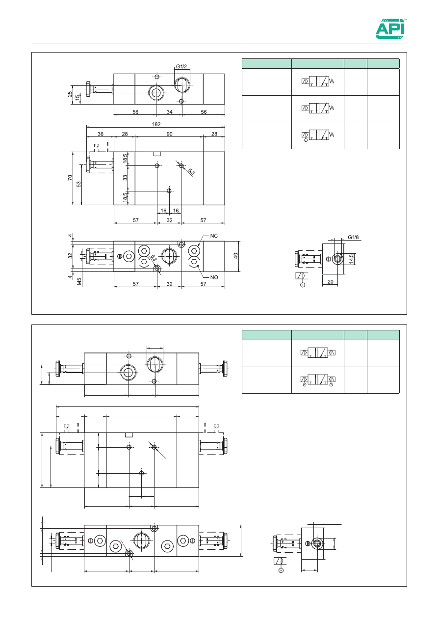
2.90.2

Valves series A1

1/2”, 3/2, electrically operated

36

28

90

182

70

53

4

32

4

56

15

25

G1/2

M5

28

G1/8

20

14,

5

34

56

5,3

57

32

57

16 16

40

5,3

57

32

57

18

,5

33

18,

5

Version

Symbol

Code 

Item

3/2 

solenoid/solenoid

10

12

2

3 1

034123

A1E432

3/2 

solenoid/solenoid

external air pilot

10

12

2

3 1

034158

A1K432

Version

Symbol

Code 

Item

3/2 NC

12

2

3 1

034113

A1E430

3/2 NO

23

2

1 3

034122

A1E431

3/2 NC

external air pilot

12

2

3 1

034137

A1K430

2

2.93.1

Valves series A1

1/2”, 5/2 - 5/3, electrically operated

Series of spool valves, with static seals, high flow, for panel 
mounting.
Coils and connectors have to be ordered separately.
For the coils type ASA12.../ASA2... 

see page 2.200.1 

For the connectors type A122... 

see page 2.210.20

Code key

Series 

Actuation

Size

Function

Options

A1

E = electrical

K =  electrical with 

external air pilot

4


=


1/2” 50 = 5/2 sol./spring

51 = 5/2 sol./sol.
52 = 5/2 sol./sol.
        differential
70 = 5/3 CC
71 = 5/3 OC
72 = 5/3 PC

BT = low temp.

        seals

Standard executions

Version

Symbol

Code 

Item

5/2 

solenoid/spring

14

4 2

5 3

1

034114

A1E450

5/2 

solenoid/solenoid

12

14

4 2

5 3

1

034115

A1E451

5/2 

solenoid/solenoid

differential

12

14

4 2

5 3

1

034139

A1E452

5/3 with closed 

centres

12

14

4 2

5 3

1

034124

A1E470

5/3 with open 

centres

12

14

4 2

5 3

1

034125

A1E471

5/3 with 

pressurised 

centres

12

14

4 2

5 3

1

034126

A1E472

5/2 

solenoid/spring,

external air pilot

14

4 2

5 3

1

034138

A1K450

5/2 

solenoid/solenoid

external air pilot

12

14

4 2

5 3

1

034140

A1K451

5/3 with closed 

centres,

external air pilot

12

14

4 2

5 3

1

034159

A1K470

5/3 with open 

centres,

external air pilot

12

14

4 2

5 3

1

034160

A1K471

5/3 with 

pressurised 

centres

external air pilot

12

14

4 2

5 3

1

034161

A1K472

On request, they can be supplied 

according to 2014/34/EU - 

ATEX

II 2Gc IIB T5
II 2Dc T100°C

Technical data

Fluid

Compressed filtered air with or without lubrication. Lubrication, if started, must be continued.

Pressure range

2,5 ÷ 10 bar

Temperature range

-10°C ÷ +60°C (standard)

-25°C ÷ +60°C (BT)

Orifice

15 mm

Flow

2900 Nl/min at 6 bar with ∆P 1 bar

Minimum piloting pressure

Spring return: 2,5 bar

Bistable: 1 bar

3 positions: 2,5 bar

Mounting

In any position

Manual override

Bistable

Response time (at 6 bar)

solenoid/spring

solenoid/solenoid

Energising: 60 ms

De-energising: 36 ms

Energising: 30 ms

De-energising: 30 ms

Materials

Body: 

Anodised aluminium 

Covers: 

Anodised aluminium 

Spool: 

Hard aluminium anodized 

Distancers: Aluminium 

Seals: 

Hydrogenated Nitrile Butadiene Rubber (HNBR)

Options

Suffix

Low temperature seals

(-25 ÷ +60°C)

BT

2.93.2

Valves series A1

1/2”, 5/2 - 5/3, electrically operated

Version

Symbol

Code 

Item

5/2 

solenoid/spring

14

4 2

5 3

1

034114

A1E450

5/2 

solenoid/spring,

external air pilot

14

4 2

5 3

1

034138

A1K450

Version

Symbol

Code 

Item

5/2 

solenoid/solenoid

12

14

4 2

5 3

1

034115 A1E451

5/2 

solenoid/solenoid

differential

12

14

4 2

5 3

1

034139 A1E452

5/3 with closed 

centres

12

14

4 2

5 3

1

034124 A1E470

5/3 with open 

centres

12

14

4 2

5 3

1

034125 A1E471

5/3 with 

pressurised 

centres

12

14

4 2

5 3

1

034126 A1E472

5/2 

solenoid/solenoid

external air pilot

12

14

4 2

5 3

1

034140 A1K451

5/3 

closed centres,
external air pilot

12

14

4 2

5 3

1

034159 A1K470

5/3 

open centres, 

external air pilot

12

14

4 2

5 3

1

034160 A1K471

5/3 with pres-

surised centres
external air pilot

12

14

4 2

5 3

1

034161 A1K472

2

2.96.1

Valves series A1

1/2”, 3/2, pneumatically operated

Series of spool valves, with static seals, high flow, for panel 
mounting.

Standard executions

Version

Symbol

Code

Item

3/2 NC

12

2

3 1

034116

A1P430

3/2 NO

23

2

1 3

034127

A1P431

3/2 

pilot/pilot

10

12

2

3 1

034128

A1P432

Code key

Series

Actuation

Size

Function

Options

A1

P = pneumatic

4


=


1/2” 30 = 3/2 NC

31 = 3/2 NO

32 = 3/2 pilot/pilot

33 = 3/2  pilot/pilot 

differential 

BT = low temp.

        seals

On request, they can be supplied 

according to 2014/34/EU - 

ATEX

II 2Gc IIB T5
II 2Dc T100°C

Technical data

Fluid

Compressed filtered air with or without lubrication. Lubrication, if started, must be continued.

Pressure range

2,5 ÷ 10 bar

Temperature range

-10°C ÷ +60°C (standard)

-25°C ÷ +60°C (BT)

Orifice

15 mm

Flow

2900 Nl/min at 6 bar with ∆P 1 bar

Minimum piloting pressure

Spring return: 2,5 bar

Bistable: 1 bar

Mounting

In any position

Materials

Body: 

Anodised aluminium

Covers: 

Anodised aluminium

Spool: 

Hard aluminium anodized

Distancers: Aluminium

Seals: 

Hydrogenated Nitrile Butadiene Rubber (HNBR)

Options

Suffix

Low temperature seals

(-25 ÷ +60°C)

BT

2.96.2

Valves series A1

1/2”, 3/2, pneumatically operated

28

90

146

70

4

32

4

56

15

25

G1/2

28

34

56

5,3

57

32

57

16 16

40

5,3

32

57

57

20

20

G1

/8

14,5

14,5

G1

/8

18

,5

33

18,

5

Version

Symbol

Code 

Item

3/2 NC

12

2

3 1

034116

A1P430

3/2 NO

23

2

1 3

034127

A1P431

Version

Symbol

Code 

Item

3/2 

solenoid/ 

solenoid

10

12

2

3 1

034128

A1P432

2

2.99.1

Valves series A1

1/2”, 5/2 - 5/3, pneumatically operated

Standard executions

Version

Symbol

Code

Item 

5/2 

pilot/spring

14

4 2

5 3

1

034117

A1P450

5/2 

pilot/pilot

12

14

4 2

5 3

1

034118

A1P451

5/2 

pilot/pilot

differential

12

14

4 2

5 3

1

034136

A1P452

5/3 with 

closed centres

12

14

4 2

5 3

1

034129

A1P470

5/3 with 

open centres

12

14

4 2

5 3

1

034130

A1P471

5/3 

with pressurised 

centres

12

14

4 2

5 3

1

034135

A1P472

Code key

Series of spool valves, with static seals, high flow, for panel 
mounting.

Series

Actuation

Size

Function

Options

A1

P = pneumatic

4


=


1/2” 50 = 5/2 pilot/spring

51 = 5/2 pilot/pilot

52 = 5/2  pilot/pilot 

differential

70 = 5/3 CC

71 = 5/3 OC
72 = 5/3 PC

BT = low temp.

        seals

On request, they can be supplied 

according to 2014/34/EU - 

ATEX

II 2Gc IIB T5
II 2Dc T100°C

Technical data

Fluid

Compressed filtered air with or without lubrication. Lubrication, if started, must be continued.

Pressure range

2,5 ÷ 10 bar

Temperature range

-10°C ÷ +60°C (standard)

-25°C ÷ +60°C (BT)

Orifice

15 mm

Flow

2900 Nl/min at 6 bar with ∆P 1 bar

Minimum piloting pressure

Spring return: 2,5 bar

Bistable: 1 bar

3 positions: 2,5 bar

Mounting

In any position

Materials

Body: 

Anodised aluminium

Covers: 

Anodised aluminium

Spool: 

Hard aluminium anodized

Distancers: Aluminium

Seals: 

Hydrogenated Nitrile Butadiene Rubber (HNBR)

Options

Suffix

Low temperature seals

(-25 ÷ +60°C)

BT

2.99.2

Valves series A1

1/2”, 5/2 - 5/3, pneumatically operated

Version

Symbol

Code 

Item

5/2 solenoid/

spring

14

4 2

5 3

1

034117

A1P450

Version

Symbol

Code 

Item

5/2 solenoid/

solenoid

12

14

4 2

5 3

1

034118

A1P451

5/2 solenoid/

solenoid

differential

12

14

4 2

5 3

1

034136

A1P452

5/3 with closed 

centres

12

14

4 2

5 3

1

034129

A1P470

5/3 with open 

centres

12

14

4 2

5 3

1

034130

A1P471

5/3 with 

pressurised 

centres

12

14

4 2

5 3

1

034135

A1P472

2

2.105.1

Solenoid valves series A2

1/4”, with multiple connector

Series of spool valves, for multi-pole connection on island  sub-
base.
This series of modern valves are innovative and highly performing:
•   With reduced overall dimensions and high flow rates;
•   Electric pilots on solenoid / solenoid version are both on same 

side;

•   Coils with low power consumption;
•   

Possibility of feeding with different pressures different valves 
( by integrating a membrane module within the base );

•   Can be set for separate internal feeding;
•   Fast and practical assembly: each valve, even if in an  interme-

diate position, can be easily replaced by individually operating on 
such valve only;

•   “Push” manual override, spring return and two position;
•   With  LED.

For bases and accessories 

see page 2.105.4

For island configuration 


see page 2.105.7

Technical data

Fluid

Compressed filtered air with or without lubrication. Lubrication, if started, must be continued.

Pressure range

Max 7 bar

Temperature range

-5 °C ÷ + 50°C

Minimum piloting pressure

Spring return: 2,5 bar

Bistable: 1 bar

3 positions: 2,5 bar

 2 - 3/2: 3 bar 

Orifice

7 mm

Flow

850 l/min

 at 6 bar with ∆P 1 bar

Mounting

In any position

Manual override

Push mono and two stable positions

Electric control

24 VDC (standard)

12 VDC (on request)

Electrical consumption

1.5 W

1.4 W

Duty cycle

100% ED

100% ED

LED

Red

Red

Materials

Body: 

Die-cast painted aluminium

Covers: PBT
Spool: 

Hard aluminium anodized

Distancers: Aluminium
Seals: 

Hydrogenated Nitrile Butadiene Rubber (HNBR)

Standard executions

Version

Symbol

Code 

Item

3/2 NC - 24VDC

14

4

3 1

036000 A230A

3/2 NC - 12VDC

036030 A230B

3/2 NO - 24VDC

14

2

1 3

036001 A231A

3/2 NO - 12VDC

036031 A231B

3/2 solenoid/solenoid - 24VDC

12

14

4

3 1

036002 A232A

3/2 solenoid/solenoid - 12VDC

036032 A232B

2-3/2 NC-NO - 24VDC

14

12

4

2

5

3

1

036040 A233A

2-3/2 NC-NC - 24VDC

14

12

4

2

5

3

1

036041 A234A

2-3/2 NO-NO - 24VDC

14

12

4

2

5

3

1

036042 A235A

5/2 solenoid/spring - 24VDC

14

4 2

5 3

1

036003 A250A

5/2 solenoid/spring - 12VDC

036033 A250B

5/2 solenoid/solenoid - 24VDC

12

14

4 2

5 3

1

036004 A251A

5/2 solenoid/solenoid - 12VDC

036034 A251B

5/3 CC - 24VDC

12

14

4 2

5 3

1

036005 A270A

5/3 CC - 12VDC

036035 A270B

5/3 OC - 24VDC

12

14

4 2

5 3

1

036006 A271A

5/3 OC - 12VDC

036036 A271B

5/3 PC - 24VDC

12

14

4 2

5 3

1

036007 A272A

5/3 PC - 12VDC

036037 A272B

Series

Function

Voltage

A2

30 = 3/2 NC
31 = 3/2 NO
32 = 3/2 solenoid/solenoid
33 = 2-3/2 NC-NO
34 = 2-3/2 NC-NC
35 = 2-3/2 NO-NO
50 = 5/2 solenoid/spring
51 = 5/2 solenoid/solenoid

70 = 5/3 CC
71 = 5/3 OC
72 = 5/3 PC

A = 24VDC
B = 12VDC

146

42

,5

50

,5

30

139

80

,6

18,

5

88

38.5

G 1/4

G 1/4

19.5

2.105.2

Solenoid valves series A2

1/4”, with multiple connector

131

18

,5

42

,5

50

,5

107.5

43

G 1/4

30

139

80

,6

18

,5

88

23.5

G 1/4

18

,5

88

43

G 1/4

3/2 NC

3/2 NA

3/2 

Version

Symbol

Code 

Item

3/2 NC - 24VDC

14

4

3 1

036000 A230A

3/2 NC - 12VDC

036030 A230B

3/2 NO - 24VDC

14

2

1 3

036001 A231A

3/2 NO - 12VDC

036031 A231B

3/2 sol./sol. - 24VDC

12

14

4

3 1

036002 A232A

3/2 sol./sol. - 12VDC

036032 A232B

Version

Symbol

Code 

Item

2-3/2 NC-NO - 24VDC

14

12

4

2

5

3

1

036040 A233A

2-3/2 NC-NC - 24VDC

14

12

4

2

5

3

1

036041 A234A

2-3/2 NO-NO - 24VDC

14

12

4

2

5

3

1

036042 A235A

2

2.105.3

146

42

,5

50

,5

30

139

80

,6

18,

5

88

38.5

G 1/4

G 1/4

19.5

Solenoid valves series A2

1/4”, with multiple connector

131

42

,5

50

,5

30

139

80

,6

18

,5

88

23.5

G 1/4

G 1/4

18

,5

88

5/2 MONO

5/2 BIST. 

19.5

23.5

G 1/4

G 1/4

19.5

Version

Symbol

Code 

Item

5/3 CC - 24VDC

12

14

4 2

5 3

1

036005 A270A

5/3 CC - 12VDC

036035 A270B

5/3 OC - 24VDC

12

14

4 2

5 3

1

036006 A271A

5/3 OC - 12VDC

036036 A271B

5/3 PC - 24VDC

12

14

4 2

5 3

1

036007 A272A

5/3 PC - 12VDC

036037 A272B

Version

Symbol

Code 

Item

5/2 sol./spring - 24VDC

14

4 2

5 3

1

036003 A250A

5/2 sol./spring - 12VDC

036033 A250B

5/2 sol./sol. - 24VDC

12

14

4 2

5 3

1

036004 A251A

5/2 sol./sol. - 12VDC

036034 A251B

2.105.4

Solenoid valves series A2

Sub-bases, accessories, SUB-D connector

Sub-bases with fix position for A2 series valves, with standard 
25 poles SUB-D connector, can be mounted on DIN EN 50 035 
guides.
On each base, one position on the opposite side of the SUB-D 
connector is dedicated to the module for the external piloting of the 
valves.
The main feeding of the valves ( 1 ) can be divided by applying an 
internal diaphragm, in case feeding with two different pressures 
should be required. 
Likewise, the exhausts ( 3 – 5 ) can be divided with the suitable 
diaphragms.
The base is mainly composed by aluminium, anodized to grant last 
in time.
The covers in PBT glass charged, are sealed with an internal o-ring 
to protect the electrical circuit from external atmospheric agents.

For the external pilot modules 


see page 2.105.5

For the feeding / exhausts diaphragms 

see page 2.105.6

Standard executions

Version

Code

Item

Base 4 positions (min.)

036011

A2B04

Base 5 positions

036012

A2B05

Base 6 positions 

036013

A2B06

Base 7 positions 

036014

A2B07

Base 8 positions 

036015

A2B08

Base 9 positions 

036016

A2B09

Base 10 positions 

036017

A2B10

Base 11 positions 

036018

A2B11

Base 12 positions 

036019

A2B12

Version

A

B

Base 4 positions (min.)

203.5

127.5

Base 5 positions

223.5

147.5

Base 6 positions 

243.5

167.5

Base 7 positions 

263.5

187.5

Base 8 positions 

283.5

207.5

Base 9 positions 

303.5

227.5

Base 10 positions 

323.5

247.5

Base 11 positions 

343.5

267.5

Base 12 positions 

363.5

287.5

2

2.105.5

Solenoid valves series A2

Sub-bases, accessories, SUB-D connector

30

139

B

A2I

A2PC

A2E

33

56

18

18

G 1/8

89

24

A

The pneumatic feeding to the valve pilots mounted on the island, is 
by a feeding module, which takes on the base a dedicated position, 
on the opposite side of the SUB-D connector.

The module can be:
•   Internal piloted, when the piloting pressure is the same as the 

main feeding on;

•   External piloted, when the piloting pressure and main feeding on 

1 are differentiated.

To complete the range, there is the blanking module for the unused 
position. The electrical connection in this case will be protected by 
a suitable plug.

Standard executions

Version

Code

Item

Feeding module 
for internal piloting

036021

A2I

Feeding module 
for external piloting

036022

A2E

Blanking module 
for unused positions

036024

A2PC

Version

A

B

Feeding module 
for internal piloting

35

65

Feeding module 
for external piloting

32

62

Blanking module 
for unused positions

35

65

Solenoid valves series A2

Sub-bases, accessories, SUB-D connector

The valve units A2 can work with two zones of different pressures by using blanking diaphragms:

•   Diaphragm for differentiated main feeding: In case two different pressures should be needed on the same island and feeding 

two separated groups of valves. In this case base should be fed on both sides;

•   Diaphragm for differentiated exhausts: In case is necessary to separate the exhausts on 3 or 5 or both. This way, the exhausts 

of two groups of valves can be conveyed separately;

Both types of diaphragms can be mounted without occupying any valve position on the base and for this reason they can be 
applied also later.

2.105.6

Area 1

Area 2

12 / 14

3

5

1

3

5

1

12 / 14

3

5

1

3

5

12 / 14

3

5

1

3

5

1

Area 1

Area 2

Area 1

Area 2

Separating 
feeding

Separating 
exhausts

Separating 
feeding and 
exhausts

Standard executions

Version

Code

Item

Blanking diaphragm 
for separeting the feedings

036020

A2T

Blanking diaphragm 
for separeting the exhausts

036027

A2S

2

Cables with multi-pole connector 25 poles, to transfer electric signals.
The cable, equipped with protection against electro-magnetic interferences, can handle up to max. 12 solenoid valves, either they 
are spring-return, solenoid/solenoid or 3 positions.
Connector is protected by a special cap resistant to water conforming to the Standard SUB-D.
Cable is conforming to normative VDE 0812 for what concern the constructive, electrical and mechanical features.
Colour of wires are conforming to Standard DIN 47100 – Earth Shielding

2.105.7

Solenoid valves series A2

Sub-bases, accessories, SUB-D connector

Standard executions

Version

Code

Item

SUB-D connector 
with 5 mt cable, 25 poles

036023

SD25-5

SUB-D connector 
with 7 mt cables, 25 poles

036025

SD25-7

SUB-D connector 
with 10 mt cables, 25 poles

036026

SD25-10

Technical data

External sheath PVC-FR GREY color (RAL7001) (CEI 20-22 II).

Connector materials

Cap: 

PBT + glass

Contacts: 

Golden brass

Screw: 

Stainless steel

Specifics of cable

25 x 0,25 mm

2


Test voltage 1500V, working tensions 250V 

Conductors electrical resistance 52,2 Ω/Km, min. insulation resist

-

ance 20 MΩ/Km

Normatives

CEI EN 60228 Cl.5 - CEI 20-22 II - CEI 20-37/0 - DIN 47100 - CEI EN 60332-1-2

Working temperature

- 20 °C ÷ + 80 °C

Protection

IP 65

62,8

47,04

SW 24

22

M3 

4-40UNC

WASHER

O-RING

4,2

Ø 

26,5

59,5

52

16,2

87,5

1 WHITE

2 BROWN

3 GREEN

4 YELLOW

5 GREY

6 PINK

7 BLUE

8 RED

9 BLACK

10 PURPLE

11 GREY-PINK

12 RED-BLUE

13 GREEN-WHITE

14 BROWN-GREEN

15 YELLOW-WHITE

16 BROWN-YELLOW

17 GREY-WHITE

18 BROWN-GREY

19 WHITE-PINK

20 BROWN-PINK

21 BLUE-WHITE

22 BROWN-BLUE

23 RED-WHITE

24 BROWN-RED

25 BLACK-WHITE

Solenoid valves series A2

Coding and code

The encoding of the islands is by using a code which identifies 
the sequence of components mounted on the base: 
after having determined which types and how many valves are 
needed, considering also eventual position to let unused, is pos-
sible to determine the number of positions of the base, internal or 
external feeding to the pilots and the tension.
The valves and diaphragms, identified with letters will complete 
the island encoding: the order of the letters will reflect the effec-
tive position of each component on the base.

The sequence of the positions start from the side of the SUB-D 
connector and end on the side of the external piloting module.

The position of the external piloting module is set, on the opposite 
side of the SUB-D, so is not necessary to indicate in the code 
that position.

Pos 01

Pos 02

Pos 03

Pos 04

Pos 05

Pos 06

Pos 07

Pos 08

Pos 09

Pos 10

Pos 11

Pos 12

2.105.8

How to order:
Base 10 positions, internal feeding of the pilots, tension 24VDC, composed by:
2 - 5/2 solenoid/spring, 1 - 3/2 NO, 1 - Feddings diaphragm, 1 - Couple of exhausts diaphragm, 2 - 5/2 solenoid/solenoid,      2 
- 5/2 solenoid/spring, 1 - 5/3 PC, 2 - Blanking module.

A2 07 GGDOPHHGGMNN

A2 _ _ _ _ _ _ _ _ _ _ _ _ _

Configuration of the base

N° 

of base 

positions

Internal feeding 

of the pilots 

Tension 24 VDC

External feeding 

of the pilots 

Tension 24 VDC

Internal feeding of 

the pilots 

Tension 12 VDC

External feeding 

of the pilots 

Tension12 VDC

04

01

11

21

31

05

02

12

22

32

06

03

13

23

33

07

04

14

24

34

08

05

15

25

35

09

06

16

26

36

10

07

17

27

37

11

08

18

28

38

12

09

19

29

39

Encoding of components on the base

Cod

Version

Item

B

3/2 NC

A230

D

3/2 NO

A231

E

3/2 solenoid/solenoid

A232

Q

2-3/2 NC-NO

A233

R

2-3/2 NC-NC

A234

S

2-3/2 NO-NO

A235

G

5/2 solenoid/spring

A250

H

5/2 solenoid/solenoid

A251

I

5/3 CC

A270

L

5/3 OC

A271

M

5/3 PC

A272

N

Blanking module

A2PC

O

Feddings diaphragm

A2T

P

Exhausts diaphragm

A2S

2

Solenoid valves series A2

Electric scheme of multiple connector 25 poles

The transferring of the signals from the PLC to the valves is through a multi-pole connector capable of manage 24 signals.
Such signals are distributed to the valves following the scheme hereunder.
Peculiarities of these valves are:

•  Simplicity of the electrical connection with each valve configuration;
•  Type of valve will not limit the maximum number of valves applicable;
•  Every type of valve can replace another maintaining the same electrical connection.

2.105.9

POS.2

POS.3

POS.4

POS.5

POS.6

POS.7

POS.8

POS.9

POS.10

POS.11

POS.12

POS.1

1

2

3

4

5

6

7

8

9

10

11

12

13

14

15

16

17

18

19

20

21

22

23

24

25

EV.1/1-14

EV.2/1-12

EV.2/2-12

EV.1/2-14

EV.2/3-12

EV.1/3-14

EV.2/4-12

EV.1/4-14

EV.2/5-12

EV.1/5-14

EV.2/6-12

EV.1/6-14

EV.2/7-12

EV.1/7-14

EV.2/8-12

EV.1/8-14

EV.2/9-12

EV.1/9-14

EV.2/10-12

EV.1/10-14

EV.2/11-12

EV.1/11-14

EV.2/12-12

EV.1/12-14

COM.

EV.1/1-14

EV.2/1-12

EV.2/2-12

EV.1/2-14

EV.2/3-12

EV.1/3-14

EV.2/4-12

EV.1/4-14

EV.2/5-12

EV.1/5-14

EV.2/6-12

EV.1/6-14

EV.2/7-12

EV.1/7-14

EV.2/8-12

EV.1/8-14

EV.2/9-12

EV.1/9-14

EV.2/10-12

EV.1/10-14

EV.2/11-12

EV.1/11-14

EV.2/12-12

EV.1/12-14


Content      ..     16      17      18      19     ..