HNC-08M CNC SYSTEM CNC Milling System. Operation Manual (V1.22 2011/01) - page 5
10 Measurement
10.1Tool Measurement
The tool measurement function can measure automatically the tool’s length
compensation value, and save the value in the tool compensation table.
10.1.1 Tool Measuring Principle and Process
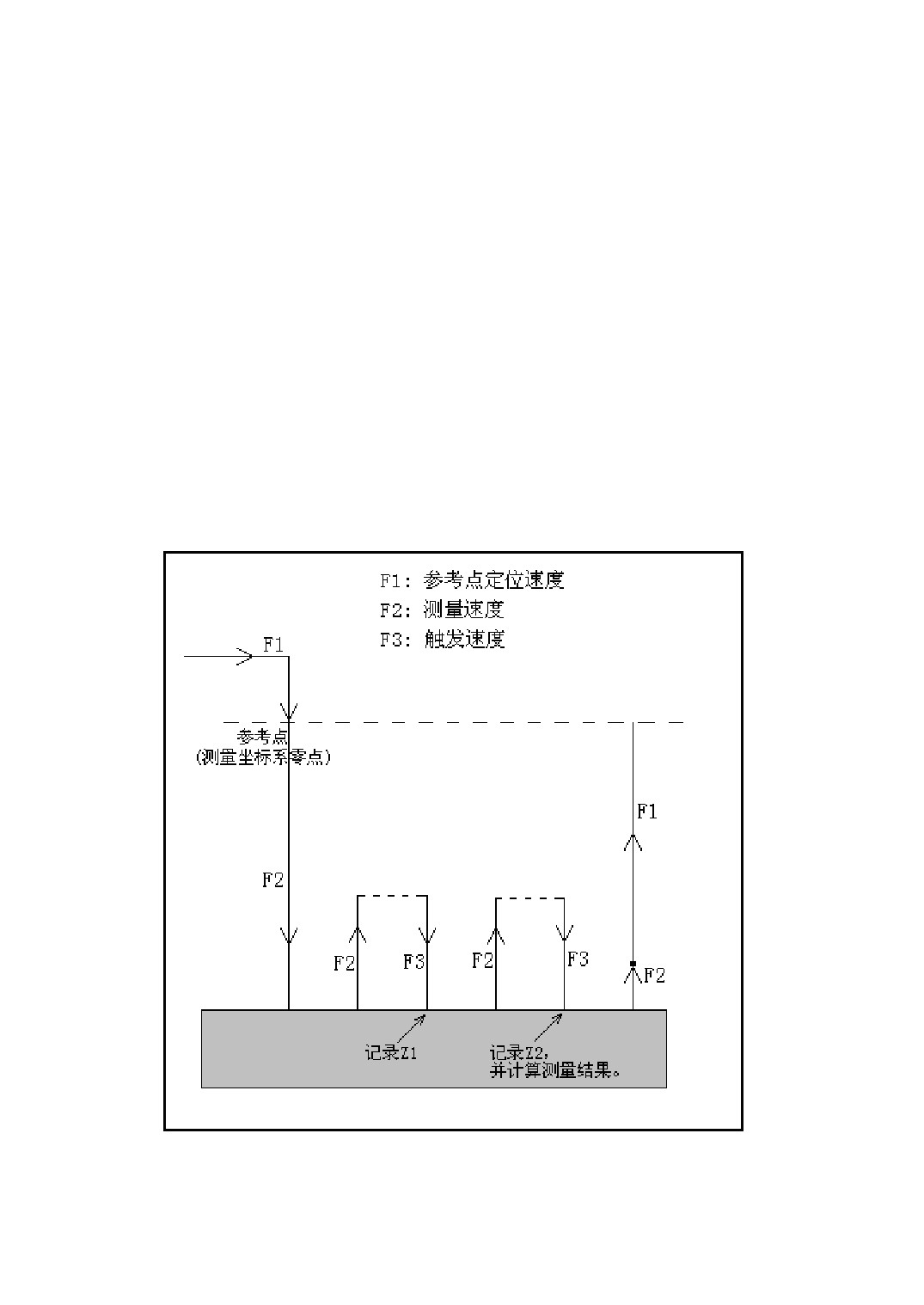
The measuring principle diagram of measurement function is shown as Figure 10-1.
Figure 10-1 Tool Measurement Process Principle Diagram
114
The process of measurement as follows:
2. If machine tool is machining center, exchange the first measure tool from tool
magazine to spindle;
3. Locate X, Y coordinates, the speed is the reference point positioning speed F1;
4. Then locate Z coordinate, the speed is the reference point positioning speed F1;
5. Tool explores downwards, the target location is the Z-axis’s lowest workpiece
coordinate, the speed is the measurement speed F2;
6. After tool touch the tool checking instrument, it will move 5mm upwards, the speed
is the measurement speed F2;
7. Tool explores downwards again, the detection distance is 6mm, the speed is the
trigger speed F3;
8. After tool touch the instrument, note the machine tool coordinate value Z1;
9. Move the tool 5mm upwards, the speed is the measurement speed F2;
10. Tool explores downwards again, the detection distance is 6mm, the speed is the
trigger speed F3;
11. After tool touch the instrument again, note the machine tool coordinate value Z2, at
the same time, calculate tool length= (Z1+Z2)/2, measurement error=Z2-Z1, and
record it into tool measurement list. If the current measure tool number is the
parameter of
“external offset measure tool”, you need to calculate
“external
workpiece zero offset (Z)”, “external workpiece zero offset (Z)”= “external offset
measurement base” -(Z1+Z2)/2.
12. Move 2mm upwards to leave the instrument, the speed is the measurement speed F2;
13. Position tool to reference point Z, the speed is reference point positioning speed F1;
14. If there are other tools to measure, system will automatically exchange next tool,
repeat the above measurement action.
10.1.2 Tool Measure Operation Sequence
The operation sequence of this function usage as follows:
1.
At first, this function needs the support of PLC, the G31.0~G31.5 of PLC
correspond to No. 1~ No. 6 measuring head. If No. 3 measuring head is used during
measuring, connect the measurement input signal of tool checking instrument to
G31.2, as Figure 10-2 shown, X04.5 is the measurement signal of the instrument. In
order to guarantee measurement precision, the programming of PLC should be
written into the primary PLC;
115
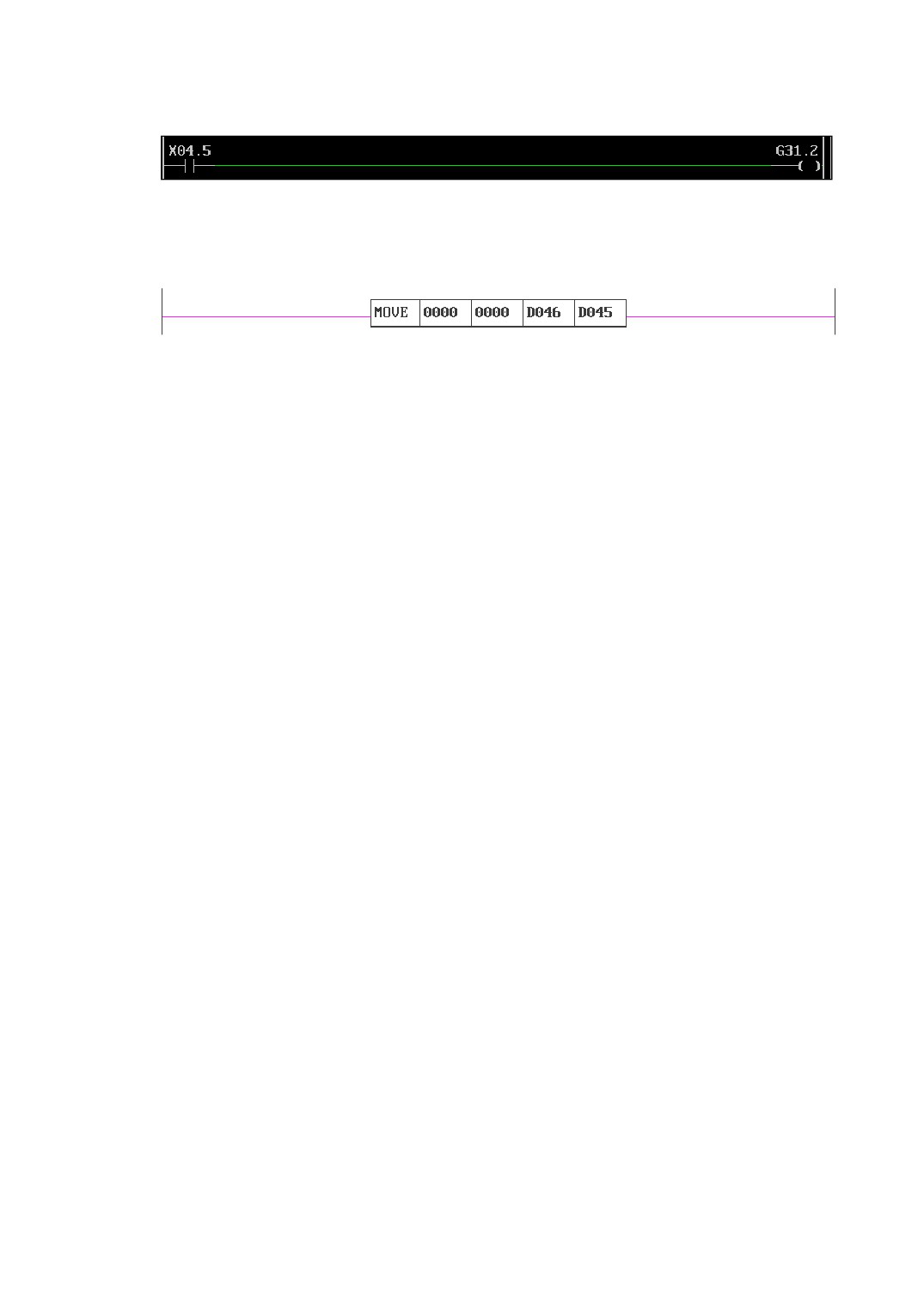
Figure 10-2 Tool Measure PLC Connection Example
If machine tool is not machining center, you need add the following command in PLC:
2.
Found measurement coordinate system: Select a coordinate system in G54~G59 as
the measurement coordinate system, the coordinate zero is measurement reference
point. The definition of measurement reference point is: X, Y is the center of tool
checking instrument, Z is the safety height, which means choose any position at the
top of tool checking instrument as the reference point’s Z coordinate, and ensure
that all of tools couldn’t collide with the tool checking instrument when moved to
the coordinate in the condition of not compensating tool. Take G54 for example, the
X, Y coordinate position of G54 coordinate system should be the center of the tool
checking instrument; the Z coordinate position of G54 coordinate system is the
middle reference point position of automatic toolsetting;
3.
Import the measurement coordinate system under MDI mode;
4.
Press <AUTO> →[\] →[→] → [TEST] → [TTST] keys to enter into the tool
length automatic measurement function interface, as Figure 10-3 shown.
116
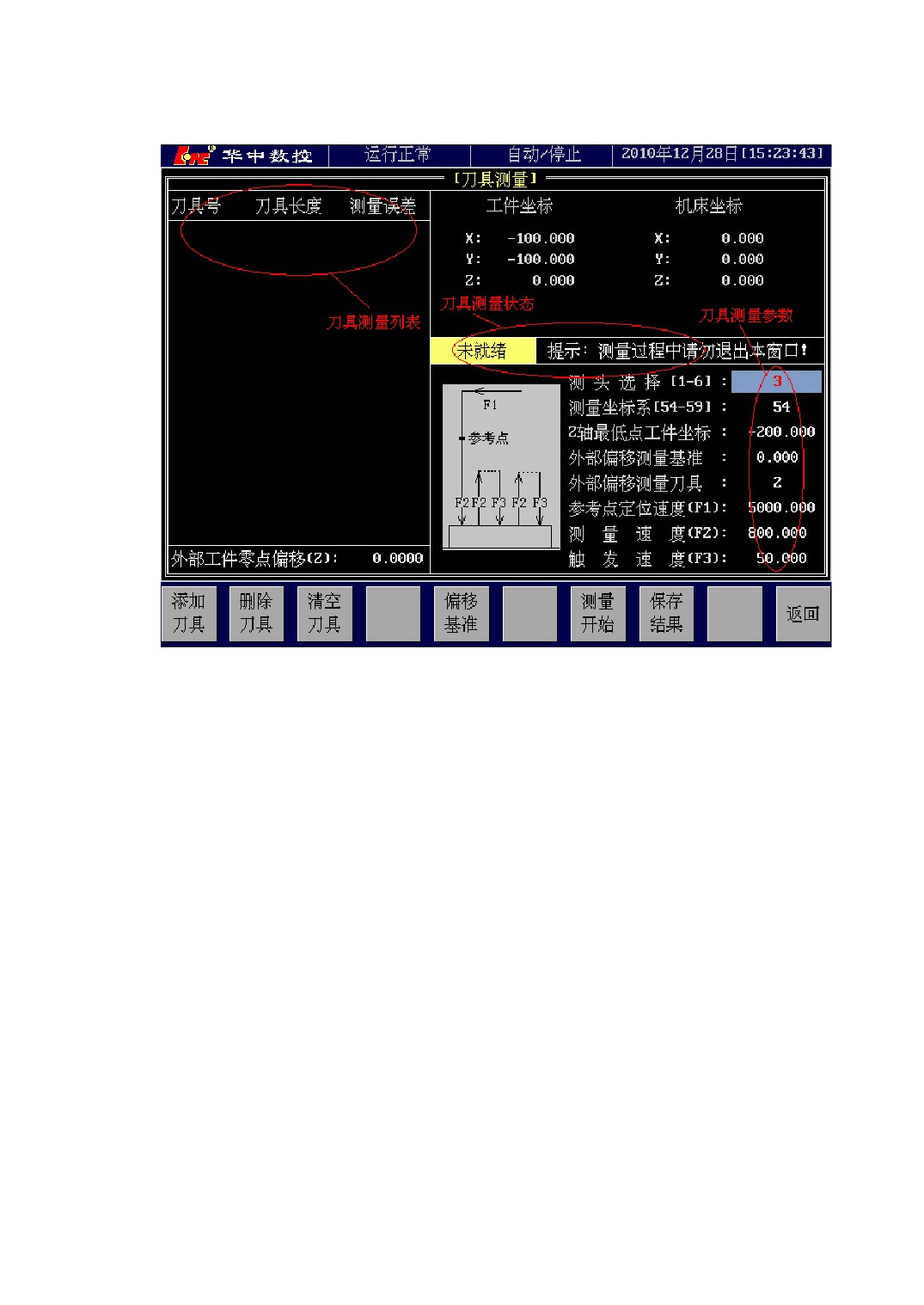
Figure 10-3 Tool Measure Interface
5.
Set the external zero offset measure parameter. Firstly, choose any tool under test to
fix on spindle, move tool to bring into contact with the upper surface of workpiece.
Press [OFBS] menu, then system will automatically store the Z-axis machine
coordinate value into “external offset measurement base”, and set the tool number
which measurement uses into “external offset measure tool”;
6.
Add the tool number under test: Press [ADDT] menu to set the measurement tool
number, as Figure 10-4 shown. If machine is the machining center, all of the needed
measurement tool number can be added to the left tool measure list box; if not, only
one tool number can be added at a time. When add a tool number, just need to set
the additive tool number to “initial tool number” in the addition tool dialog box.
Press [DELT] menu to delete the corresponding tool number of the current cursor
in the left tool measure list box.
Press [CLRT] menu to clear up the setting content in the left tool measure list box.
117
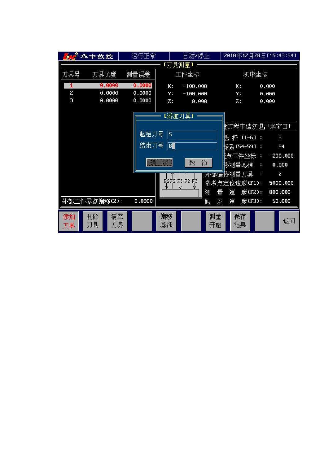
Figure 10-4 Add Measure Tool Number
7.
Set the tool measure parameter: press [←]、[→] key to move the cursor between the
left “tool measure list box” and the right “tool measure parameters box”, press [↑]、
[↓] key to move cursor among the parameter items.
Parameter items:
Measuring Head Selection [1-6]: measuring head selection can use any measuring
head from No.1 to No.6, meanwhile, measuring head needs the support of PLC.
Measurement Coordinate System [54-59]: Select the cooridnate system used by
measuring. If set as G54, G54 is the measure reference point, the X, Y cooridnate
value of G54 is the center of the tool checking instrument; the Z coordinate value of
G54 is the safety height value of automatic toolsetting.
Z-axis Lowest Point Workpiece Coordinate: Set Z-axis’s lowest point in the
process of automatic tool measure, the value is the coordinate value of Z-axis
workpiece zero in measurement coordinate system.
External Offset Measurement Base: At 5 step, press[OFBS] to automatic input.
External Offset Measure Tool: Set the adoptive tool number at 5 step to here.
Reference Point Positioning Speed(F1): The positioning speed of going to
118
measurement reference point position.
Measurement Speed(F2): Set the measuring speed, the effective stage of F2, as
measurement principle diagram shown.
Trigger Speed (F3): Set the speed that tool touch the tool checking instrument
when measuring, system will detect the touch signal in the process, so the speed should
not be set too high.
8.
Start measuring: In <AUTO> mode, after the measure tool number have been
added and the measurement parameters have been set, press [TTOK] menu, then
system will automatically create a extended program called 9700, and automatically
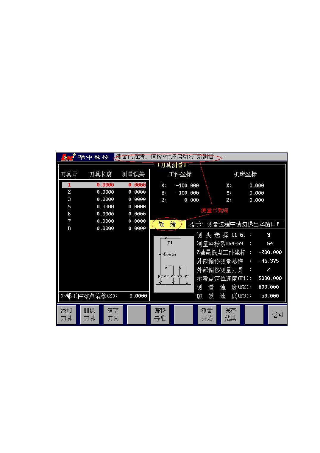
load 9700 program, the interface is shown as Figure 10-5.
Figure 10-5 Measure is Ready
Then press <CYCL> key to start automatic measuring, the interface is shown as
Figure 10-6.
119
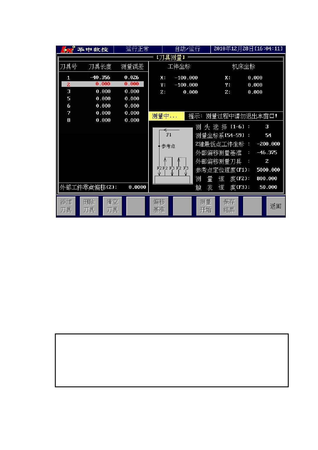
Figure 10-6 Measuring
9.
Save the measurement result: After measurement is finished, press [TTSV] menu to
store the tool length into tool compensation table, and save the external workpiece
zero offset to the parameter of P1222.
10. Reset the Z value of the used workpiece coordinate system, because the tool length
which tool measurement note and save are the values in the machine tool coordinate
system.
Note:
1、 Can not exit from measure window in the process of measuring;
2、 The whole measured tool length are relative to Z-axis zero of the machine tool
coordinate system.
120
11 Compensation Setting
11.1Reverse Backlash Compensation
Usually, there is a definite cooperation backlash between screw and workbench, the
backlash may affect the positioning precision of workbench, you need to compensate it.
The reverse backlash values of machine tool are measured by machine tool factory,
and set the measured backlash values into CNC system parameter, CNC will compensate
automatically.
The compensation values of reverse backlash are set as follows:
P0021: X-axis reverse backlash(micron)
P0022: Y-axis reverse backlash(micron)
P0023: Z-axis reverse backlash(micron)
P0024: Fourth-axis reverse backlash(micron, one thousandth of a degree)
P0025: Fifth-axis reverse backlash (micron, one thousandth of a degree)
P0026: Sixth-axis reverse backlash (micron, one thousandth of a degree)
P0027: Seventh-axis reverse backlash (micron, one thousandth of a degree)
P0028: Eighth-axis reverse backlash (micron, one thousandth of a degree)
Note:
After change a certain axis’s reverse backlash compensation parameter, you
should let the axis return the reference point by hand, or else the compensation of
CNC may be not correct.
11.2Pitch Error Compensation
Usually, screw has a definite pitch error in manufacture, the error may affect the
positioning precision of workbench, you need to compensate it.
The pitch error compensation is segmented. Firstly, divide the workbench’s travel
range into several areas, then set the compensation value for each area.
121
1) Pitch Error Compensation Starting Point
Confirm where to start compensation within the travel range of workbench. The
compensation starting points are set by the following parameters(setting value is the
coodinate position under the machine tool coordinate system):
P0041: X-axis pitch error compensation starting point
P0042: Y-axis pitch error compensation starting point
P0043: Z-axis pitch error compensation starting point
P0044: Fourth--axis pitch error compensation starting point
P0045: Fifth-axis pitch error compensation starting point
P0046: Sixth-axis pitch error compensation starting point
P0047: Seventh-axis pitch error compensation starting point
P0048: Eighth-axis pitch error compensation starting point
2) Pitch Error Compensation Interval
Confirm the distance of each segment when pitch error compensation segments
workbench travel. If the compensation interval is positive number, it will start segmental
compensation from compensation starting point towards the positive direction; if the
compensation interval is negative, it will start the segmental compensation from
compensation starting point towards the negative direction;
The compensation intervals are set by the following parameters:
P0051: X-axis pitch error compensation interval
P0052: Y-axis pitch error compensation interval
P0053: Z-axis pitch error compensation interval
P0054: Fourth-axis pitch error compensation interval
P0055: Fifth-axis pitch error compensation interval
P0056: Sixth-axis pitch error compensation interval
P0057: Seventh-axis pitch error compensation interval
P0058: Eighth-axis pitch error compensation interval
3)
Pitch Error Compensation Type
Pitch error has one-way compensation and two-way compensation, the types are set
by the following paramters:
P200: X-axis pitch error compensation type
P201: Y-axis pitch error compensation type
P202: Z-axis pitch error compensation type
P203: Fourth-axis pitch error compensation type
122
P204: Fifth-axis pitch error compensation type
P205: Sixth-axis pitch error compensation type
P206: Seventh-axis pitch error compensation type
P207: Eighth-axis pitch error compensation type
4) Pitch Error Compensation Setting value
After finished the workbench travel segmenting, the pitch error of each segment is
measured by machine tool factory, and input the measured error values into CNC
system parameters, CNC will compensate automatically.
Compensation value = instruction position - actual measured position
the pitch error compensation setting value of each segment should be the cumulative
sum of each segment’s pitch error which is before this segment (include this segment).
If set as one-way compensation, the compensation value should be written into the
axis’s positive direction pitch compensation table.
The pitch error compensation values are set by the following parameters:
P5101~P5200: X-axis positive direction pitch error compensation value[micron/one
thousandth of a degree]
P5201~P5300: X-axis negative direction pitch error compensation value[micron/one
thousandth of a degree]
P5301~P5400: Y-axis positive direction pitch error compensation value[micron/one
thousandth of a degree]
P5401~P5500: Y-axis negative direction pitch error compensation value[micron/one
thousandth of a degree]
P5501~P5600: Z-axis positive direction pitch error compensation value[micron/one
thousandth of a degree]
P5601~P5700: Z-axis negative direction pitch error compensation value[micron/one
thousandth of a degree]
P5701~P5800: Fourth-axis positive direction pitch error compensation value
[micron/one thousandth of a degree]
P5801~P5900: Fourth-axis negative direction pitch error compensation value
[micron/one thousandth of a degree]
P5901~P6000: Fifth-axis positive direction pitch error compensation value
[micron/one thousandth of a degree]
P6001~P6100: Fifth-axis negative direction pitch error compensation value
[micron/one thousandth of a degree]
P6101~P6200: Sixth-axis positive direction pitch error compensation value
123
[micron/one thousandth of a degree]
P6201~P6300: Sixth-axis negative direction pitch error compensation value
[micron/one thousandth of a degree]
P6301~P6400: Seventh-axis positive direction pitch error compensation value
[micron/one thousandth of a degree]
P6401~P6500: Seventh-axis negative direction pitch error compensation value
[micron/one thousandth of a degree]
P6501~P6600: Eighth-axis positive direction pitch error compensation value
[micron/one thousandth of a degree]
P6601~P6700: Eighth-axis negative direction pitch error compensation value
[micron/one thousandth of a degree]
Pitch Error Compensation Example 1(one-way pitch compensation---compensation
interval is positive value)
The one-way pitch error compensation of machine tool coordinate positive direction
starts from the compensation starting point.
Example:
Suppose X-axis’s compensation starting point is reference point 0, travel is 550mm,
interval is 50mm, and measure once, the parameters are set as follows:
P0041(X-axis pitch error compensation starting point) is set as 0;
P0051(X-axis pitch error compensation interval) is set as
50(the pitch error
compensation of machine tool coordinate positive direction starts from the
compensation starting point, so the value is positive);
P0200(X-axis pitch error compensation type[0-one way; 1-two way]) is set as 0.
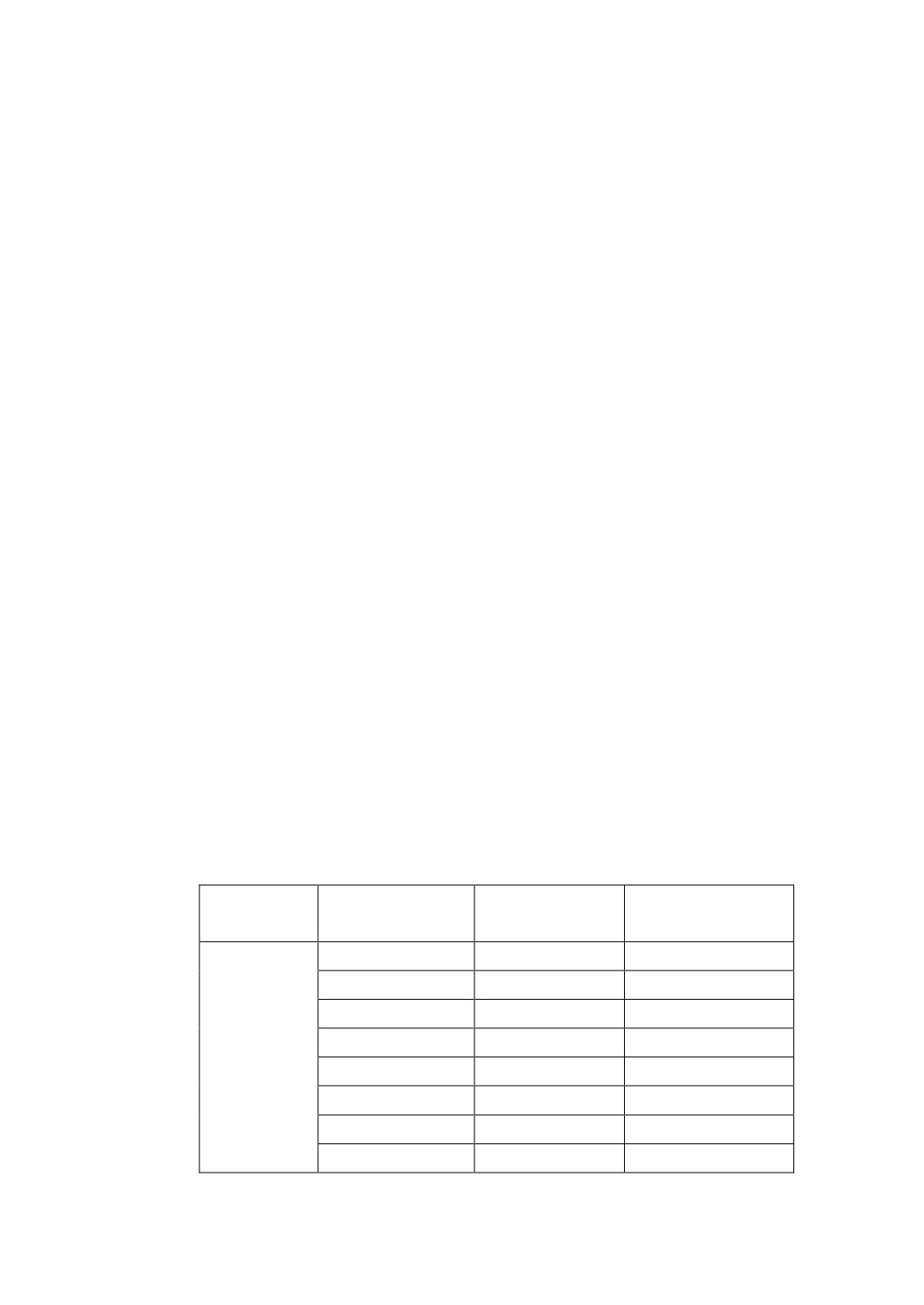
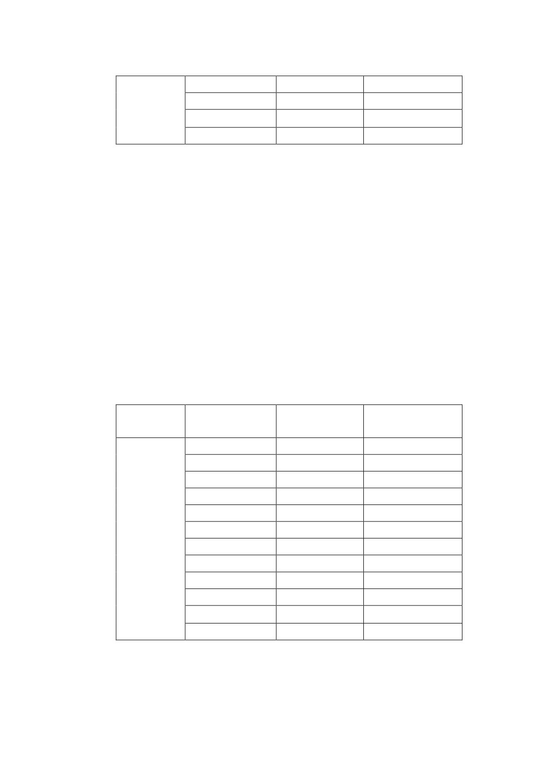
The measured X-axis’s pitch error datas and compensation setting as follows:
Motion
Instruction
Actual
Compensation table
direction
position(mm)
poistion(mm)
setting(micron)
0
0
50
49.996
P5101 = 4
100
100.003
P5102 = -3
150
150.005
P5103 = -5
Positive
200
200.015
P5104 = -15
direction
250
249.998
P5105 = 2
300
300.007
P5106 = -7
350
350.012
P5107 = -12
124
400
400.025
P5108 = -25
450
450.10
P5109 = -10
500
499.991
P5110 = 9
550
549.985
P5111 = 15
Pitch Error Compensation Example 2(one-way pitch compensation---compensation
interval is negative value)
The one-way pitch error compensation of machine tool coordinate negative
direction starts from the compensation starting point.
Example:
Suppose X-axis’s compensation starting point is reference point 0, travel is -550mm,
interval is 50mm, and measure once, the parameters are set as follows:
P0041(X-axis pitch error compensation starting point) is set as 0;
P0051(X-axis pitch error compensation interval) is set as
50(the pitch error
compensation of machine tool coordinate negative direction starts from the
compensation starting point, so the value is negative);
P0200(X-axis pitch error compensation type[0-one way; 1-two way]) is set as 0.
The measured X-axis’s pitch error datas and compensation setting as follows:
Motion
Instruction
Actual
Compensation table
direction
position(mm)
position(mm)
setting(micron)
0
0
-50
-49.996
P5101 = -4
-100
-100.003
P5102 = 3
-150
-150.005
P5103 = 5
Negative
-200
-200.015
P5104 = 15
direction
-250
-249.998
P5105 = -2
-300
-300.007
P5106 = 7
-350
-350.012
P5107 = 12
-400
-400.025
P5108 = 25
-450
-450.10
P5109 = 10
-500
-499.991
P5110 = -9
-550
-549.985
P5111 = -15
125
Pitch Error Compensation Example 3(two-way pitch compensation---compensation
interval is positive value)
The two-way pitch error compensation of machine tool coordinate positive
direction starts from the compensation starting point.
Example:
Suppose X-axis’s compensation starting point is reference point 0, travel is 550mm,
interval is 50mm, and measure once, the parameters are set as follows:
P0041(X-axis pitch error compensation starting point) is set as 0;
P0051(X-axis pitch error compensation interval) is set as
50(the pitch error
compensation of machine tool coordinate positive direction starts from the
compensation starting point, so the value is positive);
P0200(X-axis pitch error compensation type[0-one way; 1-two way]) is set as 1.
The measured X-axis’s pitch error datas and compensation setting as follows:
Motion
Instruction
Actual
Compensation table
direction
position(mm)
position(mm)
setting(micron)
0
0
50
49.996
P5101 = 4
100
100.003
P5102 = -3
150
150.005
P5103 = -5
200
200.015
P5104 = -15
Positive
250
249.998
P5105 = 2
direction
300
300.007
P5106 = -7
350
350.012
P5107 = -12
400
400.025
P5108 = -25
450
450.10
P5109 = -10
500
499.991
P5110 = 9
550
549.985
P5111 = 15
550
550.002
P5211 = -2
500
500.004
P5210 = -4
450
449.995
P5209 = 5
400
399.992
P5208 = 8
350
350.006
P5207 = -6
Negative
300
300.010
P5206 = -10
direction
250
250.003
P5205 = -3
200
199.998
P5204 = 2
150
149.993
P5203 = 7
126
100
100.005
P5202 = -5
50
50.012
P5201 = -12
0
0
Pitch Error Compensation Example 4(two-way pitch compensation---compensation
interval is negative value)
The two-way pitch error compensation of machine tool coordinate negative
direction starts from the compensation starting point.
Example:
Suppose X-axis’s compensation starting point is reference point 0, travel is -550mm,
interval is 50mm, and measure once, the parameters are set as follows:
P0041(X-axis pitch error compensation starting point) is set as 0;
P0051(X-axis pitch error compensation interval) is set as
-50(the pitch error
compensation of machine tool coordinate negaitve direction starts from the
compensation starting point, so the value is negative);
P0200(X-axis pitch error compensation type[0-one way; 1-two way]) is set as 1.
The measured X-axis’s pitch error datas and compensation setting as follows:
Motion
Instruction
Actual
Compensation table
direction
position(mm)
position(mm)
setting(micron)
0
0
-50
-49.996
P5201 = -4
-100
-100.003
P5202 = 3
-150
-150.005
P5203 = 5
-200
-200.015
P5204 = 15
Negative
-250
-249.998
P5205 = -2
direction
-300
-300.007
P5206 = 7
-350
-350.012
P5207 = 12
-400
-400.025
P5208 = 25
-450
-450.10
P5209 = 10
-500
-499.991
P5210 = -9
-550
-549.985
P5211 = -15
-550
-550.002
P5111 = 2
-500
-500.004
P5110 = 4
-450
-449.995
P5109 = -5
-400
-399.992
P5108 = -8
-350
-350.006
P5107 = 6
127
Positive
-300
-300.010
P5106 = 10
direction
-250
-250.003
P5105 = 3
-200
-199.998
P5104 = -2
-150
-149.993
P5103 = -7
-100
-100.005
P5102 = 5
-50
-50.012
P5101 = 12
0
0
Note:
After change a axis’s pitch error compensation parameter, you should let the axis
return reference point by hand, or else the compensation of CNC may be not correct.
11.3Deflection Compensation
Deflection compensation is a kind of compensation for the gantry beam bending
deformation, the setting method is the same as pitch error compensation. The main
setting parameters include:
P0270: Beam direction. The parameter confirm the coordinate direction of gantry
beam position.
P0270=0: gantry beam along the X-axis direction
P0270=1: gantry beam along the Y-axis direction
P0271: deflection compensation starting point.
P0272:deflection compensation interval. If compensation interval is positive, it will
start compensation from compensation starting point towards the positive
direction; If compensation interval is negative, it will start compensation
from compensation starting point towards the negative direction.
P5001~P5100: deflection compensation value. The unit is micron.
Note:
After change a axis’s deflection compensation parameter, you should let the axis
return reference point by hand, or else the compensation of CNC may be not correct.
128
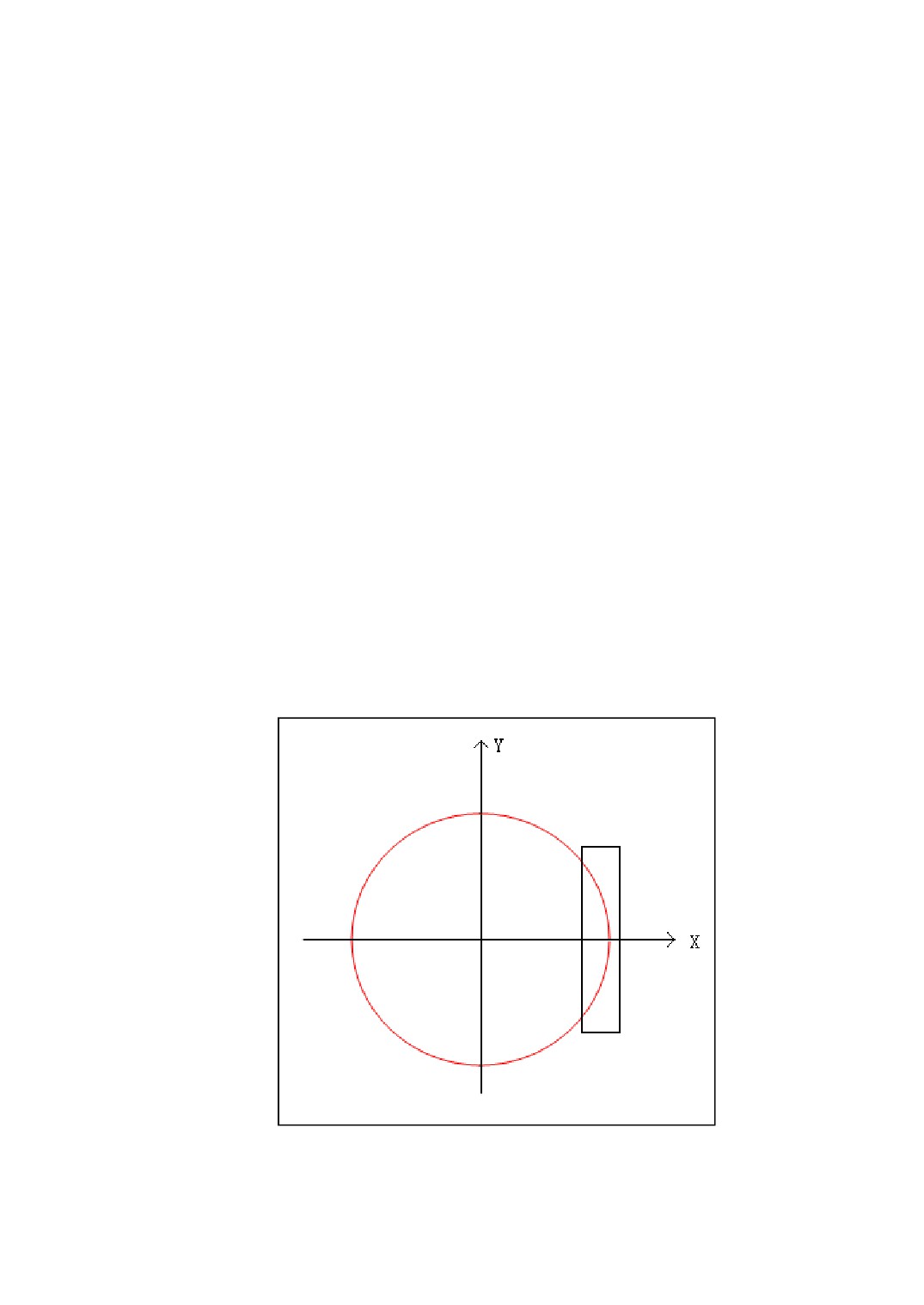
11.4Circular Arc Across Quadrant Compensation
Circular arc across quadrant is due to at the time of machine across quadrant, the
static friction force of reverse axis is greater than dynamic friction force, which lead to
the reverse axis lags behind other axis when reverse movement, this lag is called across
quadrant error. In order to improve machining precision, it is necessary to compensate
circular arc across quadrant for machine tool. The main setting parameters include:
P0210: X-axis across quadrand compensation(micron).
P0211: X-axis across quadrand compensation time(micron).
P0212: X-axis across quadrand compensation delay time(micron).
P0215: Y-axis across quadrand compensation(micron)
P0216: Y-axis across quadrand compensation time(micron).
P0217: Y-axis across quadrand compensation delay time(micron).
P0220: Z-axis across quadrand compensation(micron)
P0221: Z-axis across quadrand compensation time(micron).
P0222: Z-axis across quadrand compensation delay time(micron)
Take X-axis for example:
Figure 11-1 X-axis Across Quadrant
129
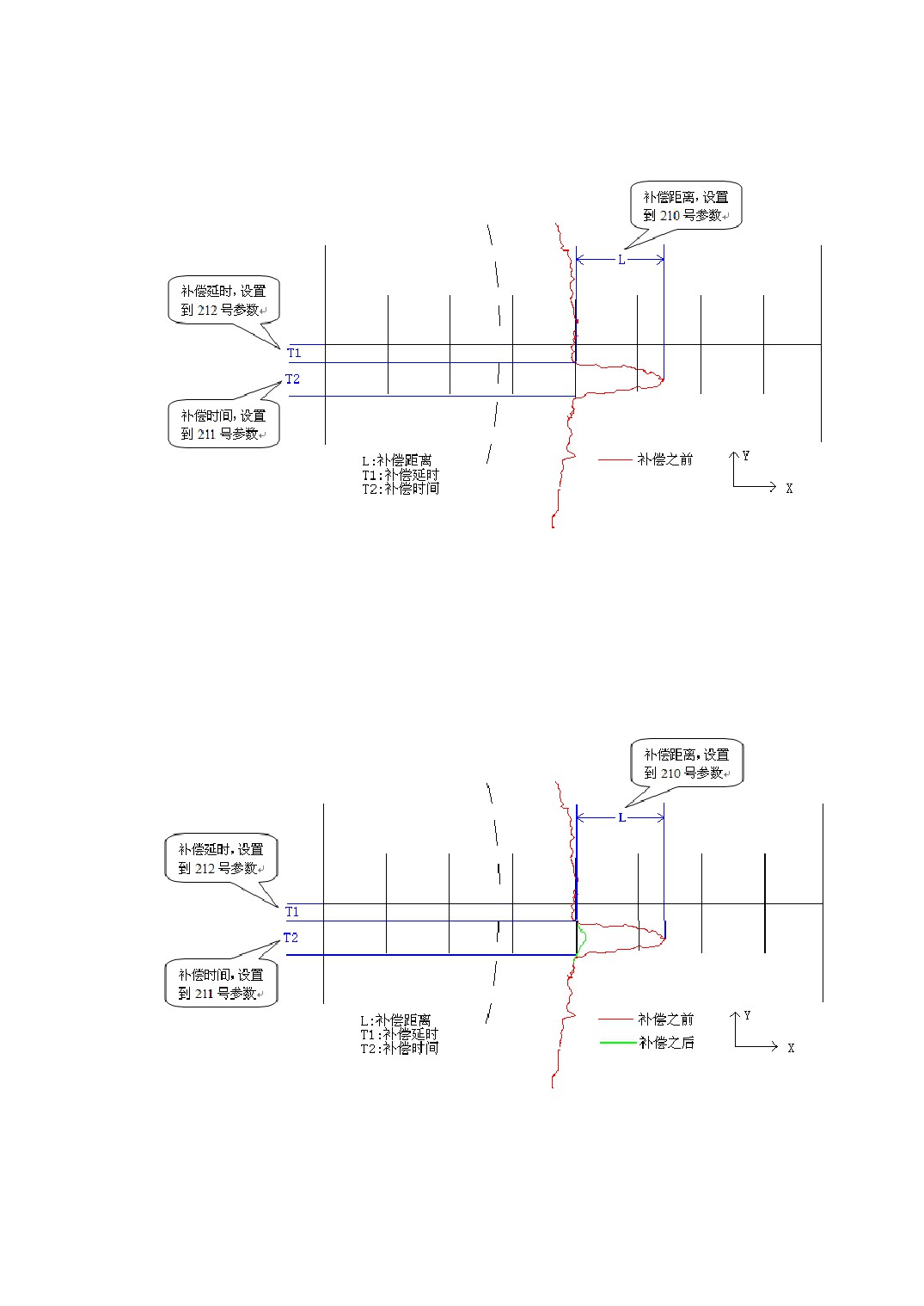
Figure 11-2 X-axis Circular Arc Across Quadrant Before Compensation
Through the correct setting of parameters P0210~P0212, commonly there can be a great
improved in the machining precision of circular arc across quadrant, as Figure 11-3
shown.
Figure 11-3 X-axis Circular Arc Across Quadrant Compensation Before and After
130
12 System Error and Solution
12.1System Alarm Indication
The alarm indicator above the CNC system screen is used to display system alarm
status. Alarm state can be divided into the following categories:
1) System Reset: After press Overtravel released key when release Emergency Stop
Switch or over travel, system needs certain time to reset. During this period,
system can not be operated, and the Alarm Display area shows “Reset”.
2) Over Travel: When the workbench stroke travel switch, system turns up overtravel
alarm and the Alarm Display area shows “Reset”.
3) Emergency Stop: When press E-Stop button down, system turns up emergency stop
alarm and the Alarm Display area shows “E-Stop”.
4) System Alarm: When turns up other alarms except the mentioned above, the Alarm
Display area shows “System-Alarm”.
When the alarms above occur at the same time, the priority displayed in the Alarm
Display area is the following (the left has high priority, that means it will be shown in
front of others when alarm appear):
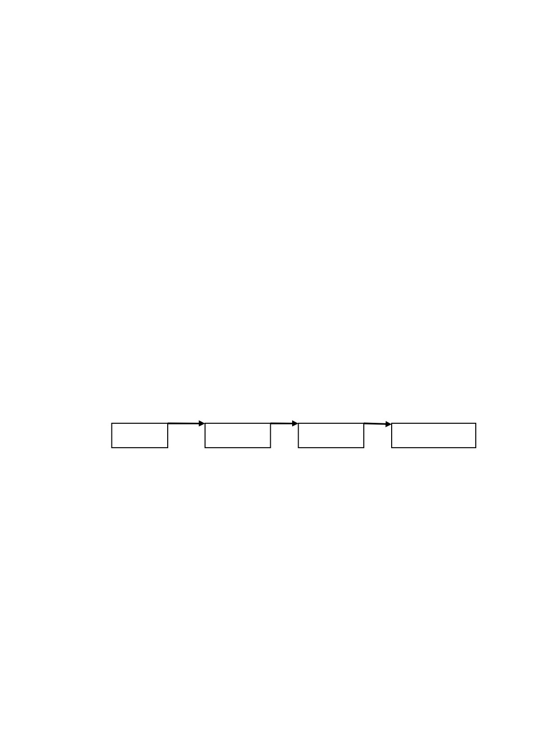
Reset
Overtravel
E-Stop
System-Alarm
12.2Alarm Information Query Window
When an alarm occurs, you can refer to the alarm query window for the details of all
alarms in the current system.
Alarm information query window is shown 错误!未找到引用源。. When a new
alarm occurs, the window will pop up automatically, or you can press the system menu [\]
→[DIAG] → [ALRM]to switch to the window.
The alarm information that the window displays includes:
1) Alarm Number: Identification number of system alarm, such as No.70, No.400 etc;
2) Alarm Commentary: Specific information to illustrate the alarm, such as
“air
131
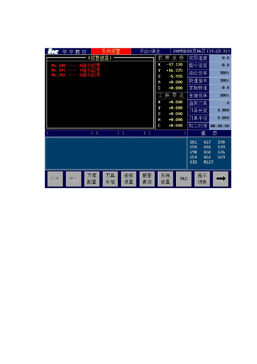
pressure alarm”, “Spindle overheat” etc.
Figure 12-1 Alarm Information Query Window
12.3Emergency Stop
Press the emergency stop button, then the machine stops working and the spindle
stops rotating immediately. other output is shut down or not depends on the definition
specified by the machine tool plant, refer to the corresponding specifications provided by
the plant for details.
To release the emergency stop to resume system operation, you just need to rotate the
emergency stop button.
12.4Stroke Travel Switch
When the motion of workbench is out of travel limit and stroke travel switch, the
machine stops working and the spindle stops rotating immediately. Whether other output
132
is shut down or not depends on the definition specified by the machine tool plant, refer
to the corresponding specifications provided by the plant for details.
To release the over travel state to resume system operation, you need to press
<OTRL> button ( do not release it now) firstly, after the resetting is successful, move
the axis in over travel state to the safety direction by hand. After move out the travel
switch, release <OTRL> button, then system resume normal operation.
12.5System Software Limits Alarm
The software limits are set by the system parameters to restrict the motion range of
each axis. When the motion beyond the range, the system software limit alarm occurs
and then all the axes decelerate to stop.
In the case of software limit alarm, programs and MDI codes can’t be executed in auto
mode. In manual mode or hand-wheel mode, you can move the axis in the alarm state
toward the safety direction, but toward the opposite direction is not. Therefore, to release
the software limit alarm, you need to switch to the manual or hand-wheel mode firstly
and then move the axis in the alarm state to the safety range.
Positive software limits are set by the following parameters:
1)
P0061: X-axis positive software limit(if greater than 99999, not detect)
2)
P0062: Y-axis positive software limit(if greater than 99999, not detect)
3)
P0063: Z-axis positive software limit(if greater than 99999, not detect)
4)
P0064: Fourth-axis positive software limit(if greater than 99999, not detect)
5)
P0065: Fifth-axis positive software limit(if greater than 99999, not detect)
6)
P0066: Sixth-axis positive software limit(if greater than 99999, not detect)
7)
P0067: Seventh-axis positive software limit(if greater than 99999, not detect)
8)
P0068: Eighth-axis positive software limit(if greater than 99999, not detect)
Negative software limits are set by the following parameters:
1)
P0071: X-axis negative software limit(if less than -99999, not detect)
2)
P0072: Y-axis negative software limit(if less than -99999, not detect)
3)
P0073: Z-axis negative software limit(if less than -99999, not detect)
133
4)
P0074: fourth-axis negative software limit(if less than -99999, not detect)
5)
P0075: fifth-axis negative software limit(if less than -99999, not detect)
6)
P0076: sixth-axis negative software limit(if less than -99999, not detect)
7)
P0077: seventh-axis negative software limit(if less than -99999, not detect)
8)
P0078: eighth-axis negative software limit(if less than -99999, not detect)
When the specified positive software limit value is greater than 99999, CNC will
not detect the positive software limit; When the specified negative limit value is less
than -99999, CNC will not detect the negative softeware limit.
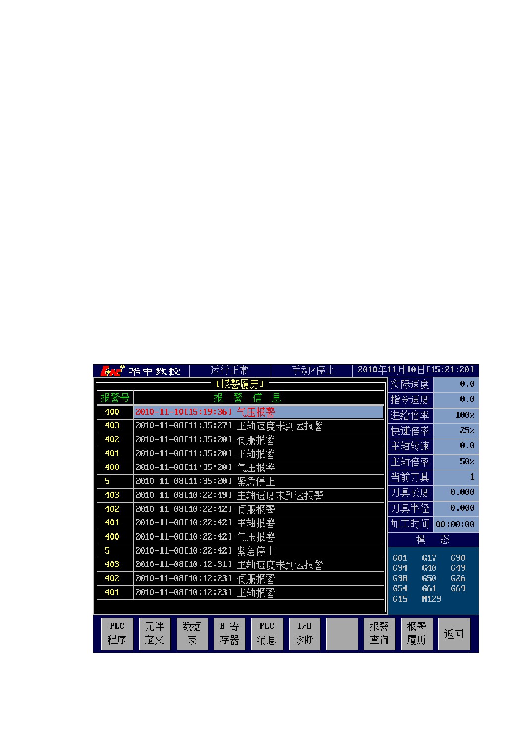
12.6System Alarm Record Query Window
Alarm record query window is the history alarm query window, as Figure 12-1 shown:
Figure 12-1 Alarm Record Query Window
134
In the alarm record query window, each item has “Alarm Number” and “Alarm
Information” two parts, the “Alarm Information” includes the date, time that alarm occur
and alarm content.
The number of alarm records that the alarm record displays is set by parameter
P0158 (the maximum number of alarm records ).
135
13 Appendix
13.1Appendix one, System Parameter Definition
P0002 —— Program Hide Setting
The parameter decides whether or not hide the [EPGM] menu in <AUTO>
→[PROG] →[LDPG]. If the parameter is set as 1, [EPGM] menu is gray and can not
be operated; if the parameter is set as 0, the [EPGM] menu is light and can be operated.
P0003 —— Program Syntax Checking Setting
If the parameter is set as 1, system will automatically check the program syntax
after loading in automatic mode; if set as 0, it will not check the syntax after loading.
P0004 —— Authority Checking Setting
If the parameter is set as 1, CNC system will check the authority, for the function
which has the authority demand (or parameters), you can not operate if lack authority; If
set as 0, system will not check the authority, all function can be operated( or parameters).
P0005 —— Software Menu Manner Setting
Modify the parameter to make the space between software menus match the panel key.
Parameter
System Type
21
—— HNC-21MD
22
—— HNC-22MD
2100
—— HNC-210A
2101
—— HNC-210B
2102
—— HNC-210C
P0007 —— Key-press Sound Switch Setting
Modify the parameter to open or close key-press sound in the process of operation.
Set as 0: close key-press sound; Set as 1: Open key-press sound.
P0012 —— External Storage Index Setting
The parameter is used to set the subarea number’s index value of external storage.
The relationship between subarea number and index value is:
Subarea Number
Index value
C
——
1
136
D
——
2
E
——
3
F
——
4
…
——
…
P0013 —— Network Sharing Disk Mapping Letter Setting
The parameter is used to set network sharing disk mapping letter. The relationship
between disk letter and index value is:
Disk letter
Index value
C
——
1
D
——
2
E
——
3
F
——
4
…
——
…
P0015 —— The Display Coordinate Type Setting
The parameter is used to set the type of display coordinate value in the main
window and the first side window.
0——Display interpolation coordinate value
1——Display the interpolation coordinate value which has been compensated (such
as reverse backlash compensation, pitch error compensation etc.)
2——Display the feedback coordinate value of machine tool
P0016 —— Setting the Display Content in the Second Side Window
0——The second side window displays workpiece coordinate zero value
1——The second side window displays synchronization error
2——The second side window displays tracking error
P0017 —— Setting the Display Content in the Main Window
0——Main window displays workpiece coordinate, and the first side window
displays machine tool coordinate
1——Main window displays machine tool coordinate, and the first side window
displays workpiece coordinate
P0019 —— Reverse Backlash Compensation Step Size
The parameter sets the maximum distance of each interpolation cycle compensation
when compensating the reverse backlash. If the reverse backlash setting value is greater
than the step size, it needs multiple cycles to compensate.
137
Unit: micron.
P0021~P0028 —— Each Axis Reverse Backlash Compensation Value
These parameters are used to set the reverse backlash compensation value of each
axis.
P0021: X-axis reverse backlash compensation value(micron)
P0022: Y-axis reverse backlash compensation value(micron)
P0023: Z-axis reverse backlash compensation value(micron)
P0024: Fourth-axis reverse backlash compensation value(micron, one thousandth of
a degree)
P0025: Fifth-axis reverse backlash compensation value(micron, one thousandth of a
degree)
P0026: Sixth-axis reverse backlash compensation value(micron, one thousandth of a
degree)
P0027: Seventh-axis reverse backlash compensation value(micron, one thousandth
of a degree)
P0028: Eighth-axis reverse backlash compensation value(micron, one thousandth of
a degree)
P0031~P0038 —— Setting the Precision of Each Axis Coordinate Display
These parameters are used to set the precision when system displays each axis’s
data, namely the display decimal digits behind radix point.
P0031: X-axis coordinate display precision(decimal digits behind radix point)
P0032: Y-axis coordinate display precision(decimal digits behind radix point)
P0033: Z-axis coordinate display precision(decimal digits behind radix point)
P0034: Fourth-axis coordinate display precision(decimal digits behind radix point)
P0035: Fifth-axis coordinate display precision(decimal digits behind radix point)
P0036: Sixth-axis coordinate display precision(decimal digits behind radix point)
P0037: Seventh-axis coordinate display precision(decimal digits behind radix point)
P0038: Eighth-axis coordinate display precision(decimal digits behind radix point)
P0041~P0048 —— Setting Each Axis Pitch Error Compensation Starting Point
These parameters are used to set the starting point of each axis pitch error
compensation. Refer to the compensation setting relevant section for the definition of
pitch error compensation starting point.
P0041: X-axis pitch error compensation starting point
P0042: Y-axis pitch error compensation starting point
P0043: Z-axis pitch error compensation starting point
138
P0044: Fourth--axis pitch error compensation starting point
P0045: Fifth-axis pitch error compensation starting point
P0046: Sixth-axis pitch error compensation starting point
P0047: Seventh-axis pitch error compensation starting point
P0048: Eighth-axis pitch error compensation starting point
P0051~P0058 —— Setting Each Axis Pitch Error Compensation Interval
These parameter are used to set the interval of each axis pitch error compensation.
Refer to the compensation setting relevant section for the definition of pitch error
compensation interval.
P0051: X-axis pitch error compensation interval
P0052: Y-axis pitch error compensation interval
P0053: Z-axis pitch error compensation interval
P0054: Fourth-axis pitch error compensation interval
P0055: Fifth-axis pitch error compensation interval
P0056: Sixth-axis pitch error compensation interval
P0057: Seventh-axis pitch error compensation interval
P0058: Eighth-axis pitch error compensation interval
P0061~P0068 P0071~P0078 —— Setting Each Axis Software Limit
Each axis can be set a pair software limit to restrict its reasonable travel range. In
normal sate, workbench should be moved in this range, when goes beyond the range,
CNC will stop the machine tool moving and give an alarm. After software limit, the limit
axis moving towards limit direction will be prohibited, you can move out toward safety
direction by hand or handwheel.
P0061: X-axis positive software limit
P0062: Y-axis positive software limit
P0063: Z-axis positive software limit
P0064: Fourth-axis positive software limit
P0065: Fifth-axis positive software limit
P0066: Sixth-axis positive software limit
P0067: Seventh-axis positive software limit
P0068: Eighth-axis positive software limit
P0071: X-axis negative software limit
P0072: Y-axis negative software limit
P0073: Z-axis negative software limit
P0074: Fourth-axis negative software limit
139
P0075: Fifth-axis negative software limit
P0076: Sixth-axis negative software limit
P0077: Seventh-axis negative software limit
P0078: Eighth-axis negative software limit
P0081~P0088 —— the First Reference Point for Each Axis
The first reference point can shift the machine tool coordinate system, the
parameters are used to set the location where the first reference point is in machine tool
coordinate system.
P0081: X-axis first reference point
P0082: Y-axis first reference point
P0083: Z-axis first reference point
P0084: Fourth-axis first reference point
P0085: Fifth-axis first reference point
P0086: Sixth-axis first reference point
P0087: Seventh-axis first reference point
P0088: Eighth-axis first reference point
P0091~P0098 —— the Second Reference Point for Each Axis
the parameters are used to set the location where the second reference point is in
machine tool coordinate system.
P0091: X-axis second reference point
P0092: Y-axis second reference point
P0093: Z-axis second reference point
P0094: Fourth -axis second reference point
P0095: Fifth-axis second reference point
P0096: Sixth-axis second reference point
P0097: Seventh-axis second reference point
P0098: Eighth-axis second reference point
P0101~P0108 —— the Third Reference Point for Each Axis
the parameters are used to set the location where the third reference point is in
machine tool coordinate system.
P0101: X-axis third reference point
P0102: Y-axis third reference point
P0103: Z-axis third reference point
P0104: Fourth-axis third reference point
P0105: Fifth-axis third reference point
140
P0106: Sixth-axis third reference point
P0107: Seventh-axis third reference point
P0108: Eighth-axis third reference point
P0111~P0118 —— the Fourth Reference Point for Each Axis
the parameters are used to set the location where the fourth reference point is in
machine tool coordinate system.
P0111: X-axis fourth reference point
P0112: Y-axis fourth reference point
P0113: Z-axis fourth reference point
P0114: Fourth-axis fourth reference point
P0115: Fifth-axis fourth reference point
P0116: Sixth-axis fourth reference point
P0117: Seventh-axis fourth reference point
P0118: Eighth-axis fourth reference point
P0120~P0128 —— Axis Lock Permission
If the axis lock permission value is 1, the corresponding axis allows lockup, then if
axis lock signal G01.2~G02.2 is 1, the corresponding axis is locked up(namely can not
be moved). If the axis lock permission value is 0, the corresponding axis doesn’t allow
lockup, even if the axis lock signal is 1, the corresponding axis can be moved normally.
P0120: Spindle lock permission
P0121: X-axis lock permission
P0122: Y-axis lock permission
P0123: Z-axis lock permission
P0124: Fourth-axis lock permission
P0125: Fifth-axis lock permission
P0126: Sixth-axis lock permission
P0127: Seventh-axis lock permission
P0128: Eighth-axis lock permission
P0140~P0147 —— Each Axis Tracking Error Permission Value
These parameters are used to set the tracking error permission value for each axis,
when the actual tracking error is greater than the setting value, system will give an alarm
and prohibit the operation of machine tool (includes Auto, MDI, Handwheel).
P0140: X-axis tracking error permission value(mm)
P0141: Y-axis tracking error permission value(mm)
P0142: Z-axis tracking error permission value(mm)
141
P0143: Fourth-axis tracking error permission value(mm)
P0144: Fifth-axis tracking error permission value(mm)
P0145: Sixth-axis tracking error permission value(mm)
P0146: Seventh-axis tracking error permission value(mm)
P0147: Eighth-axis tracking error permission value(mm)
P0158 —— the Maximum Number of Alarm Records
Set the maximum history alarm amount recorded in the alarm record interface.
P0160 —— Automatically Display the Alarm Window
If the parameter is set as 1, when system has a new alarm, system will automatically
swtich to alarm information window; if set as 0, it can not automatically swtich to the
alarm information window.
P0161 —— Whether or not Watch the Extended Program
When system calls extended program, display the content of extended program in
program box or not. Set as 1, Display the extended program content; set as 0, not display
the extended program content.
P0162 —— Autosave Position Information Setting
If the parameter is set as 1, system will autosave position information of machine
tool, the position can not be lost even if power is off ; If set as 0, it will not save the the
position, after power is off and restart, all machine tool coordinates are reset.
P0165 —— Reference Point Position Confirmation Tolerance
When the error between each coordinate position and each reference point setting value
is in the range of parameter setting, system exports the reference point confirmation
signal as 1, or else, the output is 0;
Unit: micron(beeline axis) or one thousandth of a degree(rotation axis)
Reference point confirmation signal is:
F14.0~F14.7: First reference point confirmation
F16.0~F16.7: Second reference point confirmation
F18.0~F18.7: Third reference point confirmation
F20.0~F20.7: Fourth reference point confirmation
P0170~P0177 —— Each Axis Lock Waiting Permission
0——axis lock waiting permission function close
1——axis lock waiting permission function open
142
After open axis lock waiting function, combined with PLC to set axis lock. Take the 以
fourth-axis A for example, if P173 is set as 1, the A-axis opens the axis lock waiting
function, when executes program, if there is a A-axis’s move command in the current
executive program segment, A-axis automatically swtich to A-axis lock release state,
wait for A-axis’s release signal arrives, then A-axis begins to execute move command;
After A-axis’s move command has been executed, A-axis will automatically switch to
lock up state, till A-axis’s lock signal arrives, then program continues to run.
P0180 —— Cycle Start Clean Out Graphics
The parameter is used to set whether or not automatically clean out the old
machining simulation graphics track when cycle start to run program in automatic mode.
If P0180=1, it will automatically clean out graphics window when cycle start; if
P0180=0, not clean out.
P0181~P0184 —— Graphics Zoom Coefficient
These parameters are used to set the zoom coefficient when displays machining
track in graphics window. If the setting value is greater than 1, the track is zoomed in; if
setting value is less than 1, the track is zoomed out.
P0181: the XY plane’s zoom coefficient in graphics mode
P0182: the YZ plane’s zoom coefficient in graphics mode
P0183: the XZ plane’s zoom coefficient in graphics mode
P0184: the XYZ three-dimension strack’s zoom coefficient in graphics mode
P0187 —— Whehter or not Display Speed Curve
Press [VSWT] menu, whether or not display speed curve interface.
0——not display speed curve
1——display speed curve
P0188 —— The Maximum of Speed Curve
Set the maximum show value of display speed curve, unit: mm/min
P0189 —— The Maximum of Acceleration Curve
Set the maximum show value of display acceleration curve, unit: mm/s.s
P0190 —— The Type of Display Curve
0——the display curve is instruction speed or acceleration value curve
1——the display curve is actual speed or acceleration value curve
143