HNC-08M CNC SYSTEM CNC Milling System. Operation Manual (V1.22 2011/01) - page 4
6.10Statistic Information
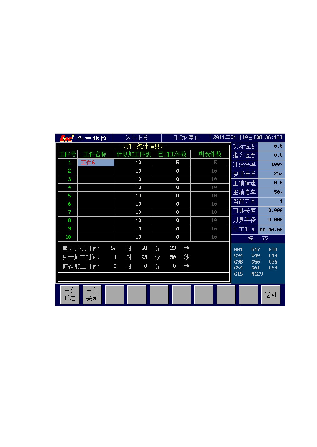
Statistic information function is the statistic of workpiece machining number of
pieces and machining time. Method of entering into statistic information menu is: [\]
→[→] → [STAT], statistic information interface is shown as Figure 6-10.
Statistic information can count the workpiece machining by M extension code.
Statistic information notes the statistic of all kinds of machining time in the process
of workpiece machining.
Figure 6-10 Statistic Information Interface
You can select “Workpiece Name”, “Plan Machining numbers”, “Already Machining
numbers” to modify by pressing [←]、[→] 、[↑]、[↓]key; select “Cumulative Boot Time ”,
“Cumulative Machining Time”, “Previous Machining Time” by pressing [←]、[→] 、
[↑]、[↓]key and press [Del] key to delete the selected target item.
The method of counting the workpiece machining numbers, please refer to the machine
illustration of machine manufacturer.
84
7 PLC
7.1 PLC Online Programming and Diagnosis
This system use ladder diagram language to PLC program. Please refer to <<PLC
Programming illustration>> about programming method of ladder diagram language.
This section doesn’t explain the programming method, only detailedly introduce the
usage of programming environment(programming interface).
7.1.1 Ladder Diagram Programming Interface
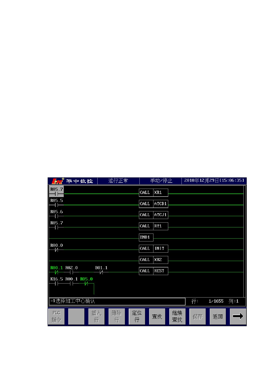
Method of entering into PLC programming interface: [\] →[DIAG] → [PDIA]
PLC programming interface is shown as Figure 7-1.
Figure 7-1 PLC Programming Interface
85
7.1.2 Ladder Diagram program Structural Unit
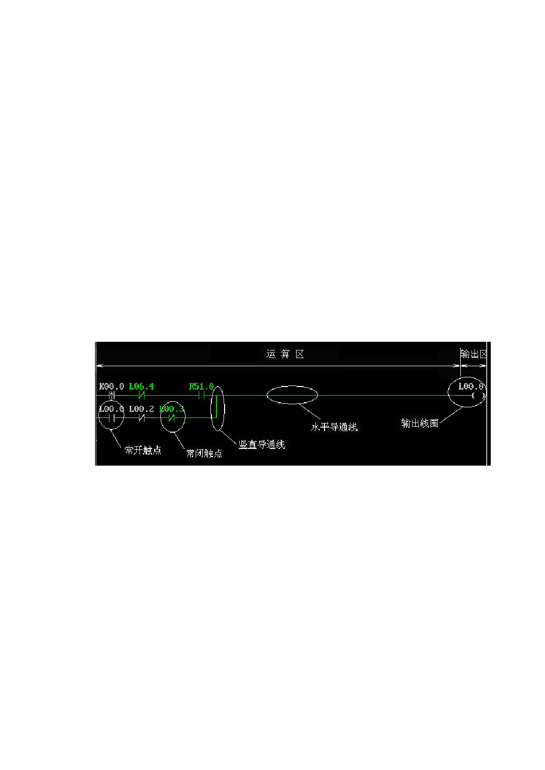
The ladder diagram program is divided into calculation section and output section.
The calculation section includes every semaphores which participate in ladder diagram
operation. The semaphore in calculation section can be a input semaphore or a output
semaphore. PLC program can only read the semaphores in calculation section. The
output section is the output edit section of the calculation result, which is used to
specify the output address of the calculation result. The semaphore of output section
can only be a output semaphore, and PLC program can write this semaphore.
PLC ladder diagram program is made up of normally open contact, normally closed
contact, level conduction line, vertical conduction line, output coil, normally open
contact rising edge, normally open contact falling edge, normally closed contact rising
edge, normally closed contact falling edge, set output, reset output and function
commands etc. as Figure 7-2 shown.
Figure 7-2
PLC Ladder Diagram Program’s Basic Unit
86
7.1.3 Programming Menu Illustration
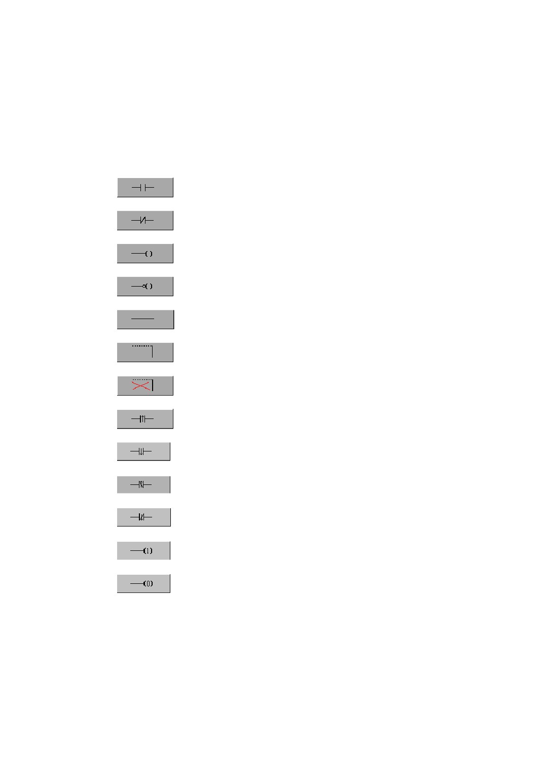
7.1.3.1Basic Command Menu
Normally Open Contact
Normally Closed Contact
Output Coil
Output Coil(output in reverse)
Level Conduction Line
Vertical Conduction Line
Delete Vertical Conduction Line
Normally Open Contact Rising Edge
Normally Open Contact Falling Edge
Normally Closed Contact Rising Edge
Normally Closed Contact Falling Edge
Set Output
Reset Output
7.1.3.2Function Command Menu
After select [FCMD] key in [PDIA] menu, the right of PLC edit interface will list a
list selected box of PLC function commands. You can select the function command in
87
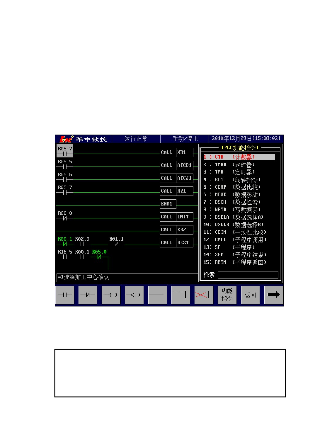
the lis box, as Figure 7-3 shown. Pressing [↑]、[↓] key to move cursor to select
function command, as well as inputing function command name for searching in search
box, or direct input the corresponding sequence number of function command. After the
cursor selects the function command, press
[Enter] key, and then the function
command of cursor selected is input into PLC edit interface. Continue to press [FCMD]
or [Esc] key to exit the right list selected box of PLC function commands.
Please refer to <<PLC Programming illustration>> about the concrete usage of
function command.
Figure 7-3 PLC Function Menu Interface
Note:
1、 Due to the function command may take up more lines or more columns, you need
remain enough room to edit when input function command.
88
7.1.3.3Ladder Diagram Edit Menu
1.
[INSL]
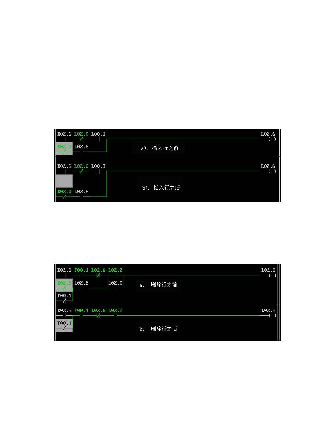
Insert a new line in front of the line in which the current cursor is positioned.
After inserting a line, the line in which the current cursor is positioned becomes a
blank line, the line behind the cursor will move downwards one line distance in turn, as
Figure 7-4 shown.
Figure 7-4
Insert a Line
2.
[DELL]
Delete the line in which the current cursor is positioned.
After deleting a line, the line in which the current cursor is positioned is deleted, the
line behind the cursor will move upwards one line distance in turn, as Figure 7-5 shown.
Figure 7-5
Delete a Line
If the line in which the current cursor is positioned has function command, when
the cursor rests on function command, [DELL] will delete the whole line program. If the
cursor rests on basic command, [DELL] will delete a length of basic command in which
the current cursor is positioned(do not delete function command).
89
3.
[LSKR]
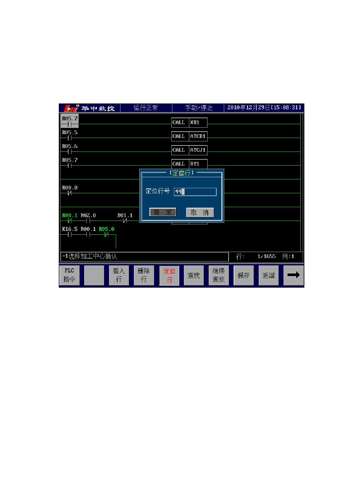
Move the current line in which the cursor is positioned to any line of ladder
diagram, input the target position where the cursor is needed to move into the dialog box
as Figure 7-6 shown. After pressing [Enter] key, the cursor will move to the new
position.
Figure 7-6 Positioning Function
4.
[FIND]、[FDON]
Finding function is used to search the specified element by name in ladder diagram.
You should input a whole element name in finding dialog. Such as searching Y00.3,
you should input “Y00.3”, but not the simply name such as “Y3” or “Y03” ect. The
small letter of input name will be translated into capital letter when searching.
After searching the target element, you can press [FDON] menu to find on the next
target backwards without inputing the element name again.
5.
[LSAV]
Save ladder diagram into system, and write into disk for permanent preservation.
When edit ladder diagram, CNC will copy the system PLC program, all of the edit
90
are on this copy. Therefore, during edit, the CNC executive program is the old PLC
program. After saving the ladder diagram, CNC will replace the old PLC program with
the new program, so the CNC begin to execute the new PLC program after saving.
6.
[PCPY]
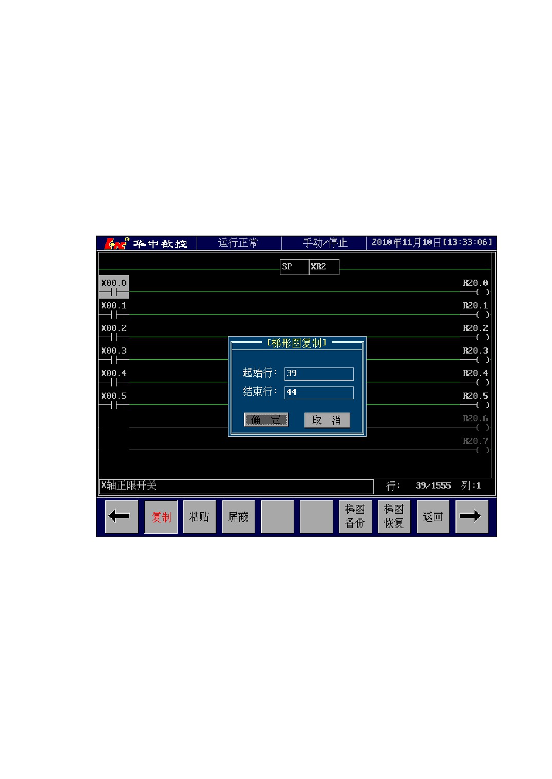
Copy function means copy an area of ladder diagram into the paste buffer, which is
used for paste function. When pressing [PCPY] menu, a dialog box appears as
Figure 7-7 shown, input the start line and the end line are into the dialog and press
[Enter] key, then the copy function is carried out.
Figure 7-7 Ladder Diagram Copy
7.
[PPST]
Paste the content copied by copy function to the line position in which the current
cursor is positioned.
8.
[MASK]
When use mask function, you should move the cursor to the right output node. You
can mask this output node or cancel mask by pressing [MASK] menu, as Figure 7-8
91
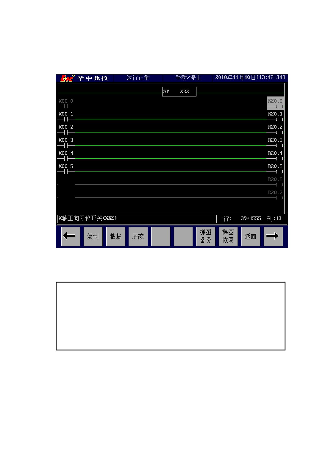
shown. After the output node is masked, the node’s calculation section and output
section turn gray, and drop out of PLC scan operation.
Figure 7-8 Mask Function
Note:
(1)
[MASK] menu can only be operated in output node, the operation in the
other node is invalidation.
(2)
[MASK] operation modify PLC, so after [MASK] operation, you need
press [LSAV] to put the scan operation result of [MASK] into effect.
9.
[LBKP]、[LRSM]
Ladder diagram backup means copy the PLC program file and store into backup
storage, you can resume this backup PLC program as the system executive PLC program
by using recovery function when you need.
Ladder diagram recovery means resume PLC backup program in backup storage as
92
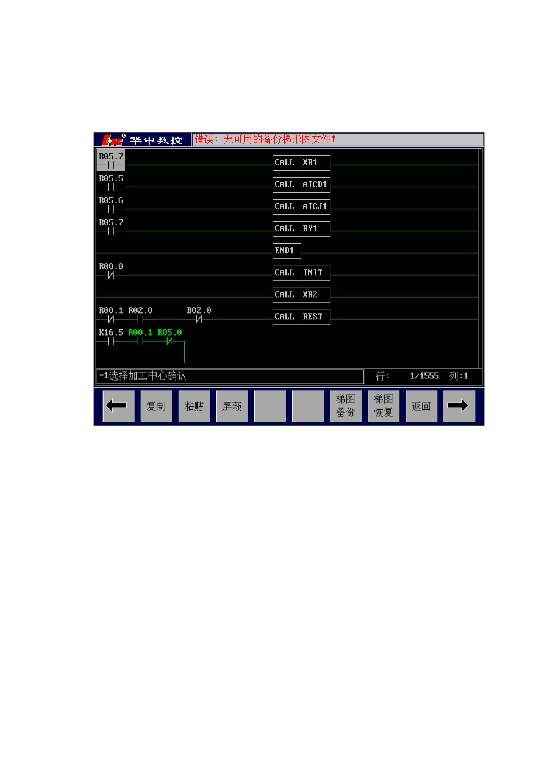
system executive PLC program. If there is no usable backup ladder diagram file in the
backup storage, when you press [LRSM] menu, the system titile bar will pop up a
prompt as Figure 7-9 shown.
Figure 7-9
No Backup Ladder Diagram
10. [INSN]
Insert a new blank node in front of the node which the current cursor selects.
After insert a node, the node position where the current cursor is positioned turns
into a blank node, the nodes behind cursor will move backwards a node distance in turn
(includes their vertical conduction lines), the position of output coil is fixed, as Figure
7-10 shown.
If the line in which the current cursor is positioned has function command, [INSN]
menu is invalidation.
93
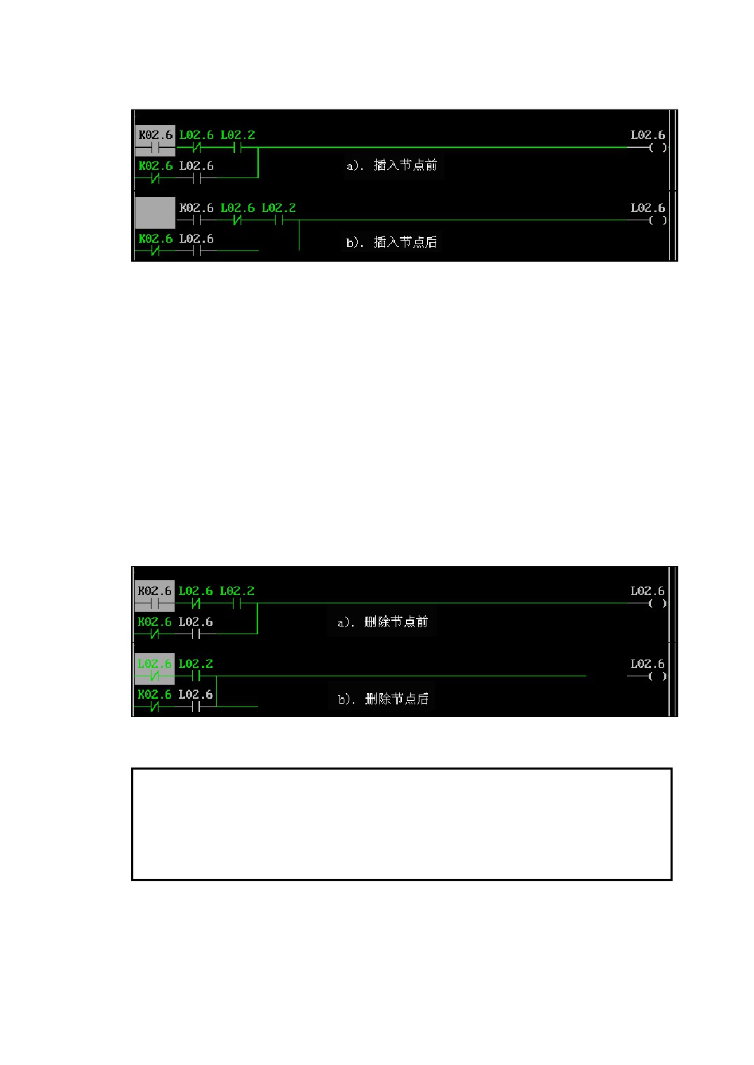
Figure 7-10 Insert a Node
11. [DELN]
Delete the node which the cursor selects.
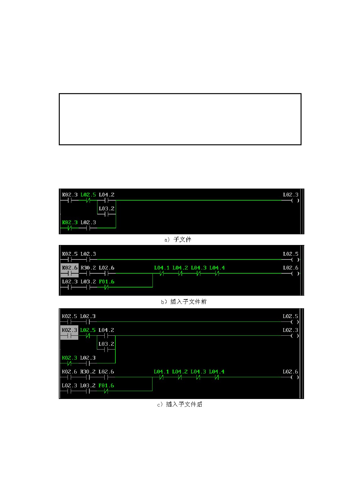
After delete the cursor position node, the nodes behind cursor will move forward a
node distance in turn(includes their vertical conduction lines), the position of output coil
is fixed, as Figure 7-11 shown.
If you want to delete the current node and keep the follow-up node’s position still,
you can direct press the [Delete] key on edit keyboard to delete the node where the
current cursor is positioned.
[DELN] menu is not valid for function command, If you want to delete function
command, please move the cursor onto any place of function command, then press
[Delete] key on edit keyboard to delete the function command.
Figure 7-11 Delete a Node
Note:
If the line in which the current cursor is positioned has function command,
[DELN] menu is invalidation.
12. [REPL]
Replacing element function means replace all of the specified element in ladder
diagram with the other specified element.
94
Input the replaced element name into “Search object” box and input the new
element name after replacing into “replace with” box in the repalcing element dialog
box, then press [Enter] key to replace all of the replaced element in PLC edit interface
with the new element name.
Note
Repalcing a element is start from the location where the current cursor is
located, the replaced element in front of cursor can not be finded out and replaced.
13. [FINS]
Insert the content of the specified ladder diagram’s subfile into the location where
the current cursor is positioned, as Figure 7-12 shown.
Figure 7-12 Insert a Subfile
95
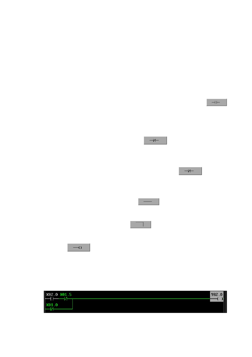
7.1.4 Ladder Diagram Programming Demonstration
Using normally open, normally closed contacts and output coil to realize the
command of and, or, invert ect.
For example, in order to realize the operation command of Y02.0 = (X02.0 &
(/X01.5)) | (/X01.0)( thereinto, ‘/’ means in reverse), programming sequence of ladder
diagram is as follows:
1)
Locate the cursor in the section start of programming position, press
( normally open contact), input address number “X02.0” into element input box and
press [Enter] to confirm, the X02.0 element will appear at the current cursor
position;
2)
Move the cursor to right for a bit, press
( normally closed contact),
input address number “X01.5” into element input box and press [Enter] to confirm,
the X01.5 element will appear at the current cursor position;
3)
Locate the cursor in the section start of next line, press
( normally
closed contact), input address number “X01.0” into element input box and press
[Enter] to confirm, the X01.0 element will appear at the current cursor position;
4)
Move the cursor to right for a bit, press
(Level Conduction Line), draw a
level conduction line at the current cursor position;
5)
Move the cursor up for a bit, press
(Vertical Conduction Line), draw a
vertical conduction line at the lower right of current cursor position;
6)
Press
(Output Coil), input address number “Y02.0” into element input
box and press [Enter] to confirm, it will automatically create output coil and
necessary level conduction line.
The finished ladder diagram is shown as Figure 7-13.
Figure 7-13 Ladder Diagram Demonstration
96
7.1.5 PLC Online Diagnosis
When PLC program is in the running process, you can observe its running process
and result by ladder diagram display interface.
In the ladder diagram interface, in calculation section, green node shows its element
is in the on-state, white node shows its element is in the off-state; In output section,
green node shows its element outputs 1, white node shows its element outputs 0.
7.2 I/O Diagnosis
7.2.1 I/O Diagnosis Summarize
I/O diagnosis is used to diagnose the register’s state table of PLC running state by
on-line observing every register’s state which is correlative with PLC.
The registers which can be seen in I/O diagnosis include:
X Register: the switching signal which machine tool inputs into PLC.
Y Register: the switching signal which PLC outputs to machine tool.
F Register:the switching signal which NC system inputs into PLC.
G Register: the switching signal which PLC outputs to NC system.
K Register: the switching signal which control panel inputs into PLC.
L Register: the switching signal which PLC outputs to control panel.
R Register: PLC internal middle register.
B Register: PLC internal breakpoint save register.
7.2.2 I/O Diagnosis Interface
Method of entering into I/O diagnosis interface: [\] →[DIAG] → [SDIA]
I/O diagnosis interface is shown as Figure 7-14 shown.
97
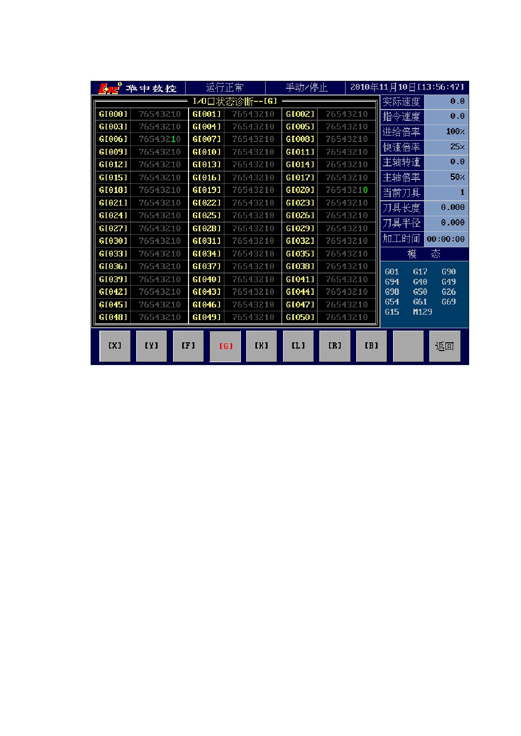
Figure 7-14 I/O Diagnosis Operation Interface
Select to corresponding I/O diagnosis by pressing register select keys at the bottom
of interface.In the diagnosis list, group as a unit, each group has 8 bit to display. If one
bit display color is green, means its semaphore is 1; if the display color is gray, means its
semaphore is 0.
7.3 PLC Data Table Setting
7.3.1 Summarize
The bulk of the processing in PLC program are switching signal, their value are 0 or
1, but sometimes PLC program needs to deal with non-switching signal too. For the
processing of non-switching signal, such as tool number when exchange tool and the
processing of taking count of tool position, then you need to use data table.
The storage space size of data table is 512 cells(address range is 0~511), every cell
can be used as single byte, double byte or four byte. Data table includes two parts,
98
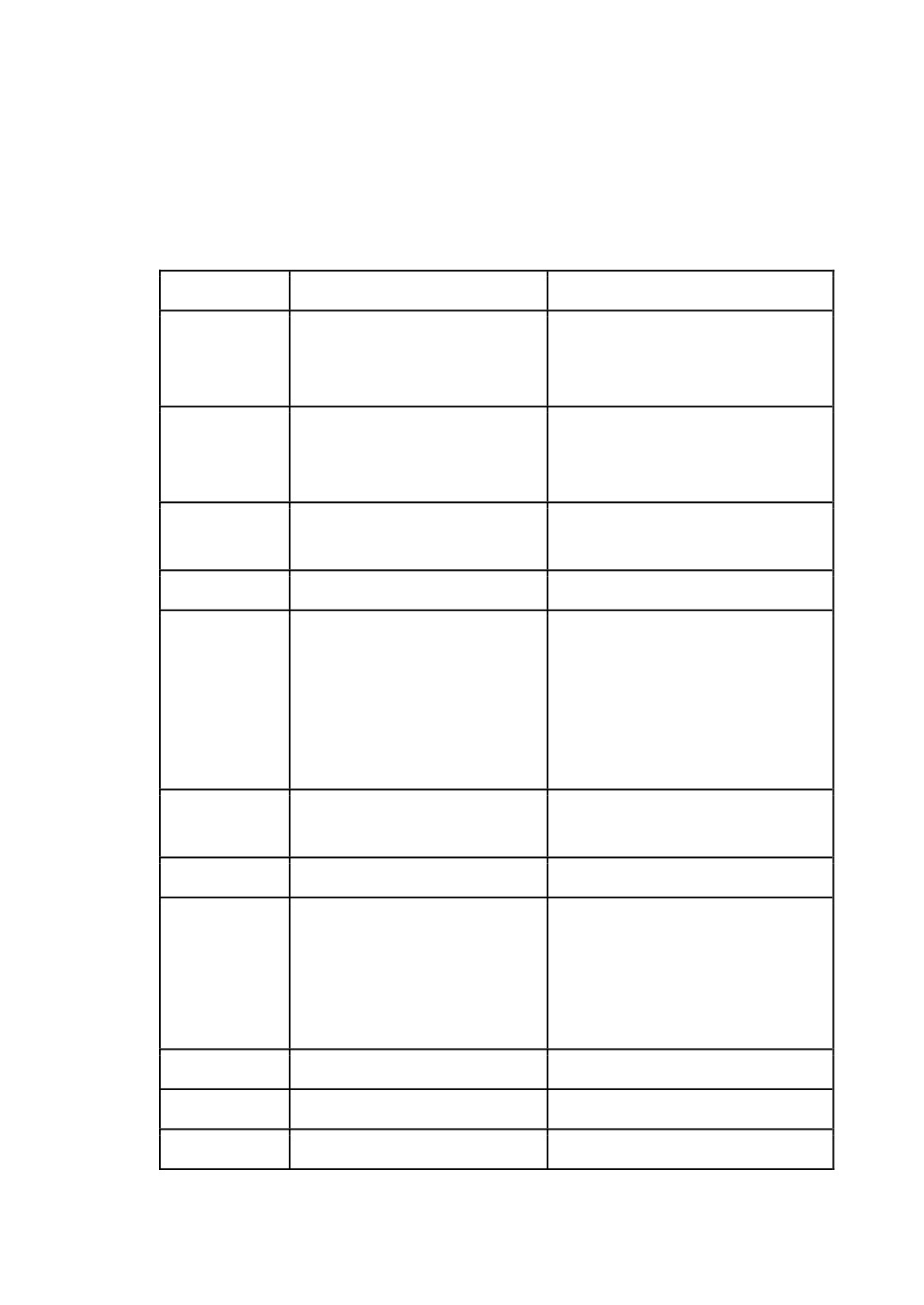
thereinto, address range 0~399 are nonvolatility storage cells, the storage data can not
be lost even power is off; Address range 400~511 are volatility storage cells, the
storage data can be lost when power is off, reset as 0 after electrified over again.
The distribution condition of data table is shown as the following table: (the address
space of the table list is CNC system fixed allocation).
Address
Use
Remark
D044
Current Tool Position Number
the tool position number which is
on the tool change position in tool
magazine.
D045
Current Tool Number
Store the tool number which is
used on spindle, if the value is 0,
means no tool is on the spindle.
D046
T command storage cell
Store T command sended by CNC
for change tool using.
D047
S command storage cell
Store S command sended by CNC.
D060~D099
1~20 Counters take up
They are storage cells of
1~20
counters in turn. Every counter has
two continuous cells, the first cell
stores preset value, the next stores
count value. Twenty counters take
up 20×2=40 cells in all.
D100~D139
1~40 Timers take up
They are timing setting values of
1~40 timers in turn, in millisecond.
D150~D157
PMC axis command
D170~D189
1~10 Workpieces statistic
They are statistic setting cells of
1~10 workpieces in turn. Every
workpiece has two continuous
cells, the first cell stores preset
value, the next stores statistic.
D400
Feedrate override
D401
Rapid traverse speed override
D402
Spindle override
99
7.3.2 Data Table Operation Interface
Data table can be read out or written in. The operation about data table can be in the
PLC program, or direct search and modify in data table operation interface. Method of
entering into data table interface: [\] →[DIAG] → [DTBL]
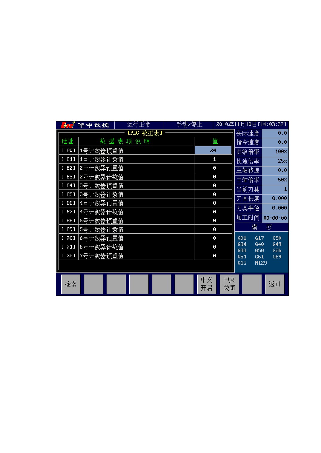
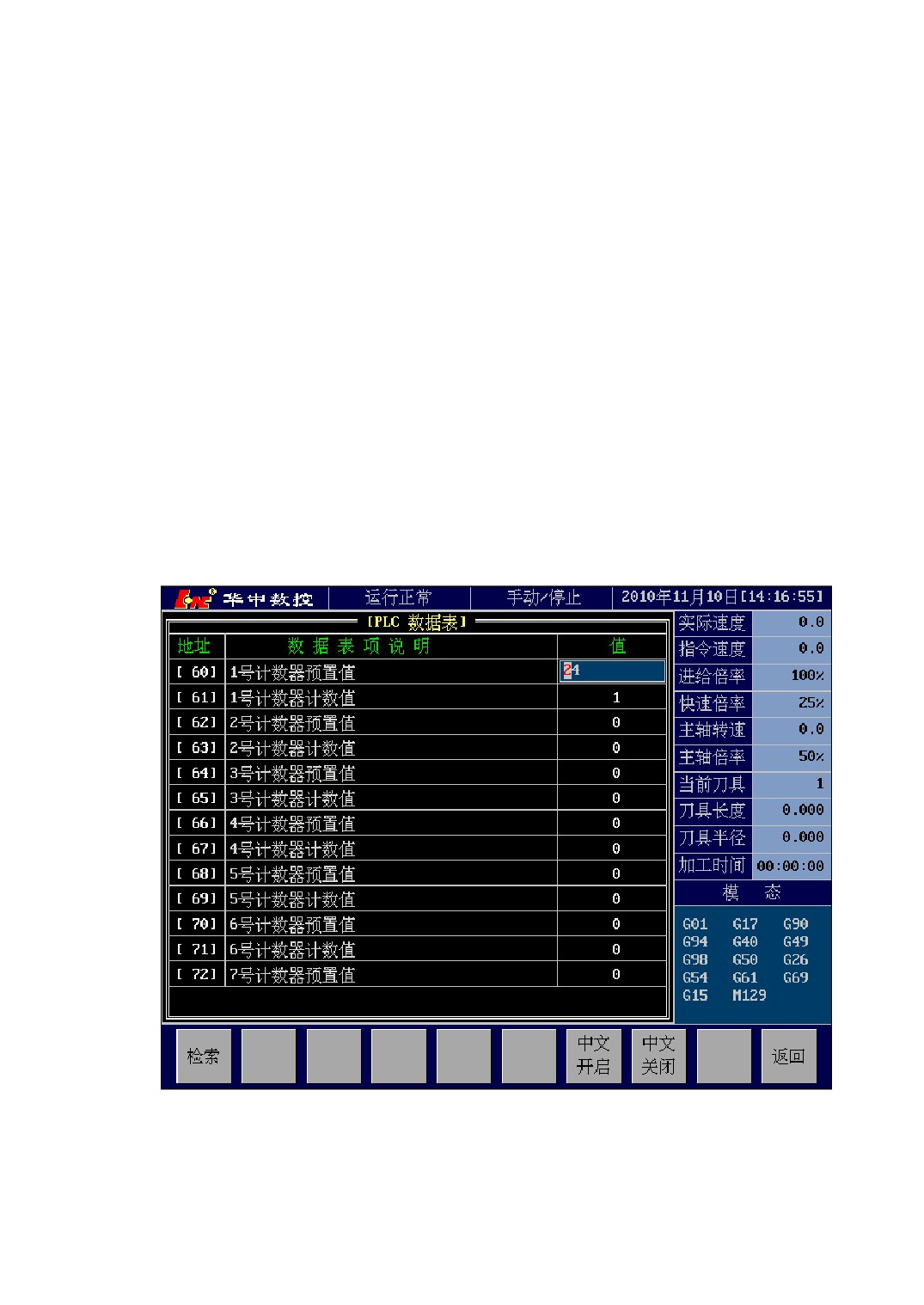
The data table interface is shown as Figure 7-15.
Figure 7-15 Data Table Operation Interface
Each item of data table are made up of three parts:
1) Address The storage cell’s order address in data table. PLC program call on a
certain item in data table according to this address.
2) Data Table Item Explanation
A sort of explanation for data table item’s
use condition.
Such as: Address [60] is “NO. 1 counter preset value” for NO.1counter use.
Address [61] is “NO. 1 counter count value” for NO.1counter use.
3) Value Means the data value which the data table’s storage cell stores.
100
7.3.3 Method of Data Table Setting
The data which is stored into every cell in data table can be modified by PLC
program command(see
<<Ladder Diagram Programming illustration>> for
correlation command), or modified by hand in data table operation interface.
The sequence of data table setting by hand is as follows:
1) Switch to data table interface.
2) Press the [↑]、[↓] or [PageUp]、[PageDown] keys to select the data table cell
needed to modify;
3) Press [Enter] key to confirm the selected or direct input a set value, then a
input box will pop up above the selected data table item (as Figure 7-16
shown);
4) Input a new data in the pop-up input box;
5) Affirm the input is correct, then press the [Enter] key to confirm input. (the
input box will disappear, and the selected item shows the new input data);
Figure 7-16 Data Table Modification
101
Note:
1) Press [Enter] key to make it valid after input a new data in the input box;
2) CNC system will save new modified data when data table window is closed;
7.4 PLC Element Definition
7.4.1 PLC Element Definition Summarize
PLC element definition define and remark the meaning of regsiter’s every signal bit
for easy understanding the meaning of every register signal bit in PLC program. Element
definition can define all of PLC registers, and support chinese definition.
7.4.2 PLC Element Definition Interface
Method of entering into element definition interface: [\] →[DIAG] → [LDEF]
The element definition interface is shown as Figure 7-17.
102
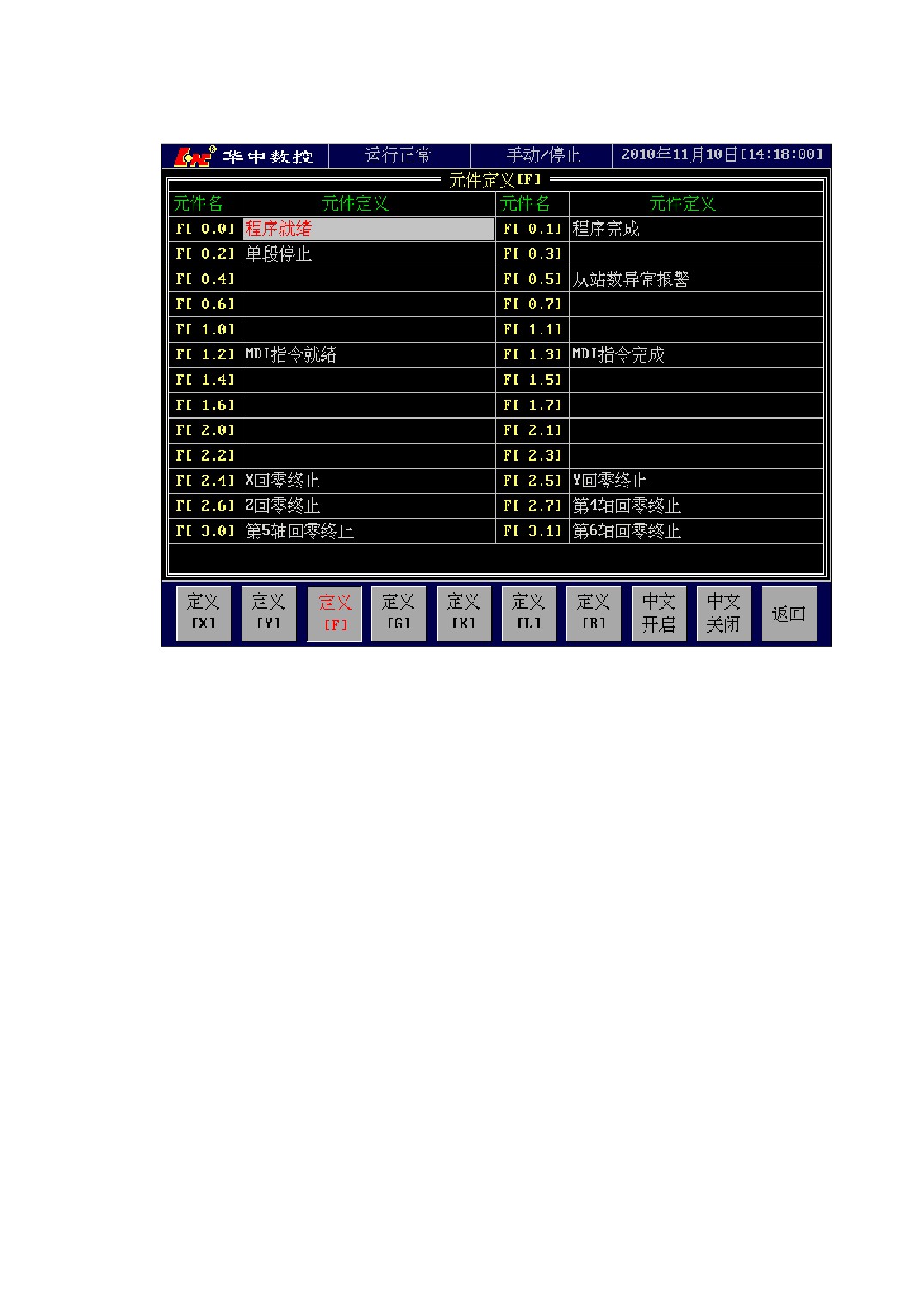
Figure 7-17 PLC Element Definition Interface
In PLC program, if the cursor selected element has definition, you can see the
definition content at the left bottom. Such as: F[2.4] is defined as “X return zero
termination” in element definition, as Figure 7-17 shown, then if you move the cursor to
F[2.4] element in PLC program, you can see the remark of F[2.4] “X return zero
termination” at the left bottom, as Figure 7-18 shown.
103
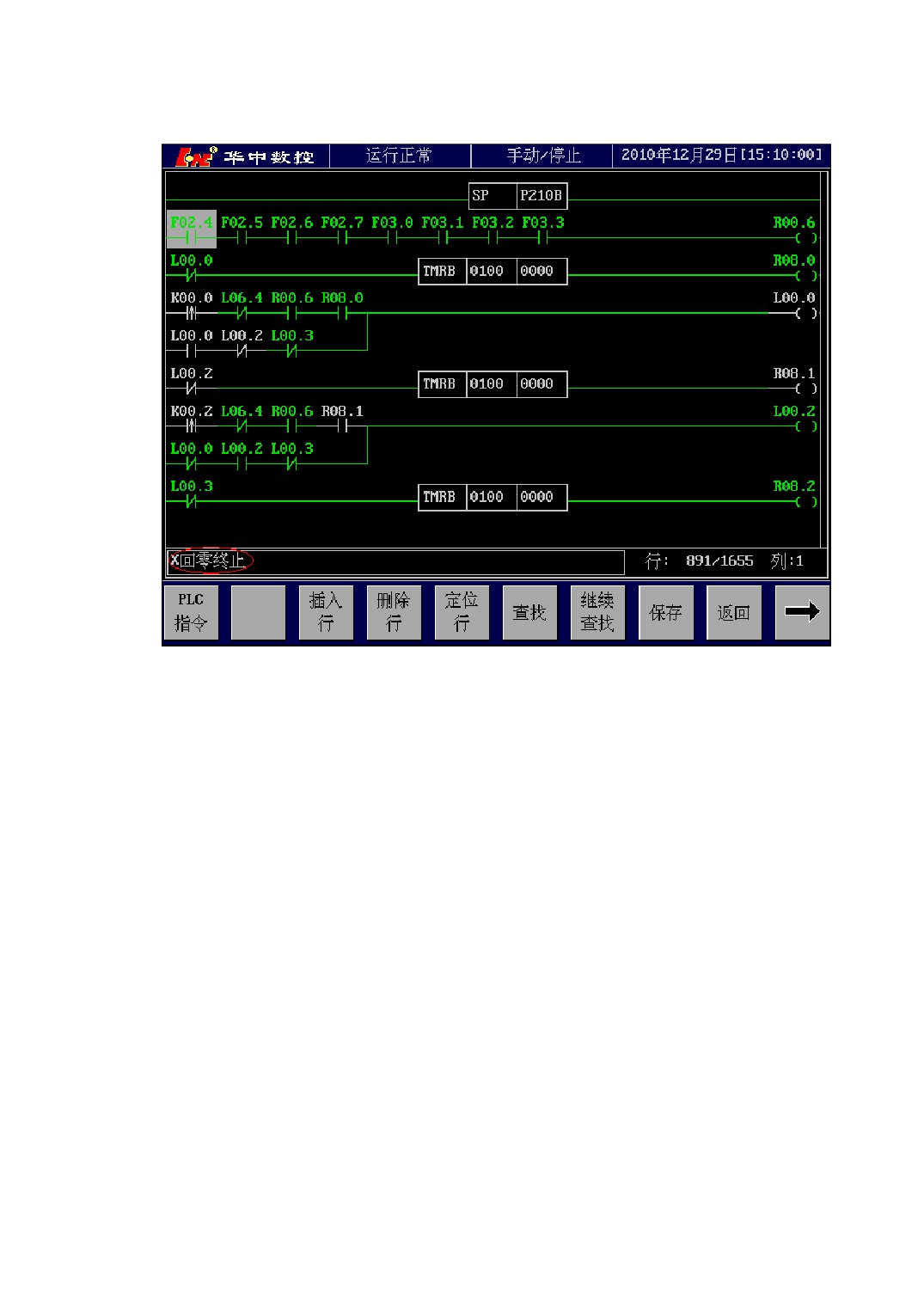
Figure 7-18 Element Remark in PLC Program
7.5 B Register
7.5.1 B Register Summarize
B register is a sort of power-off save register.
The address range of B register is B00.0~B31.7, every B register can be read and
write by PLC, and the storage data can not be lost even though power is off.
7.5.2 B Register Operation Interface
The operation about B register can be in the PLC program, or search and modify in
B register operation interface, thereinto, the modification of B00.0~B15.7 needs machine
104
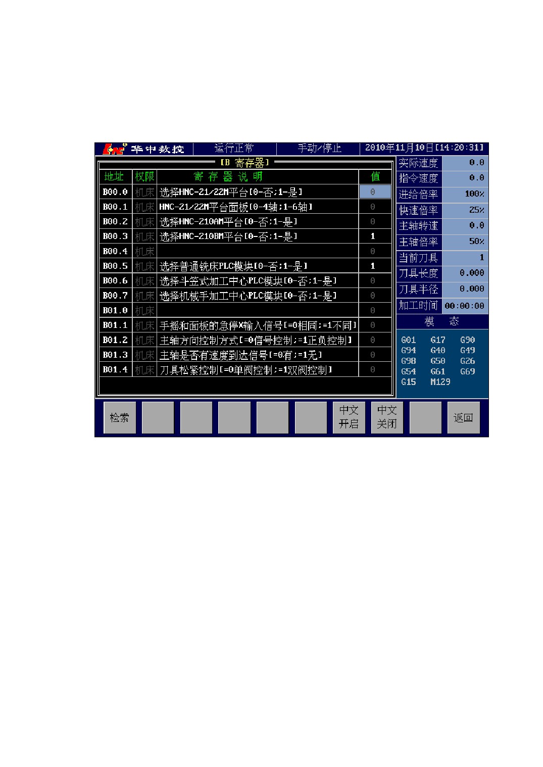
tool level operating right, and the B16.0~B31.7 needs user level operating right.
Method of entering into B register interface: [\] →[DIAG] → [BREG]
The B register interface is shown as Figure 7-19.
Figure 7-19 B Register Interface
Each item of B register are made up of four parts :
1) Address B register’s address.
2) Right The needed authority of modifying this item in B register interface.
3) Register explanation A sort of explanation for B register use condition.
4) Value
The value corresponding to B register’s address, which can be used
for searching and modifying.
105
7.6 PLC Message
7.6.1 PLC Message Summarize
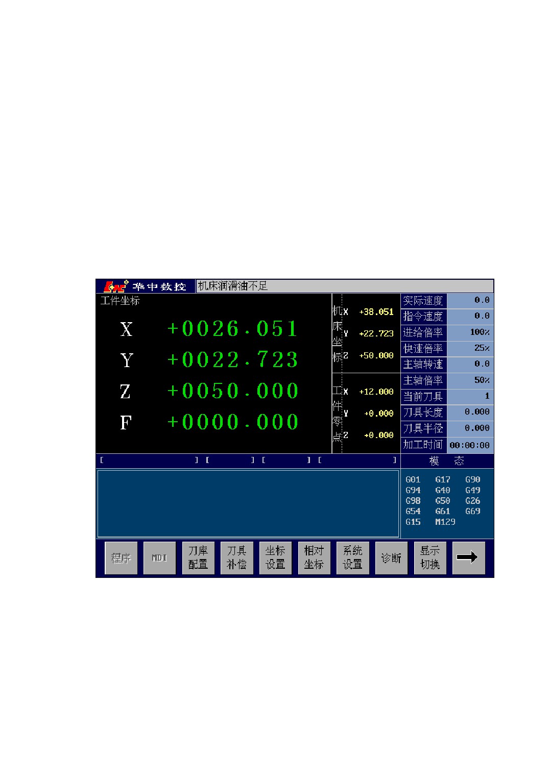
The suggestive alarm messages which are disposed by PLC will be displayed in the
system title bar by using the function command WMSG of PLC. Thereinto, the function
command WMSG specifies PLC message number, the alarm content which the number
corresponds to is set by【PLC Message】setting interface. If the title bar come forth a
prompt alarm, pressing any key can remove the display alarm, as Figure 7-20 shown:
Figure 7-20 System Displays PLC Message
7.6.2 PLC Message Operation Interface
The definition of PLC message is in【PLC Message】interface, method of entering
into PLC message interface is as follows: [\] →[DIAG] → [PMSG]
106
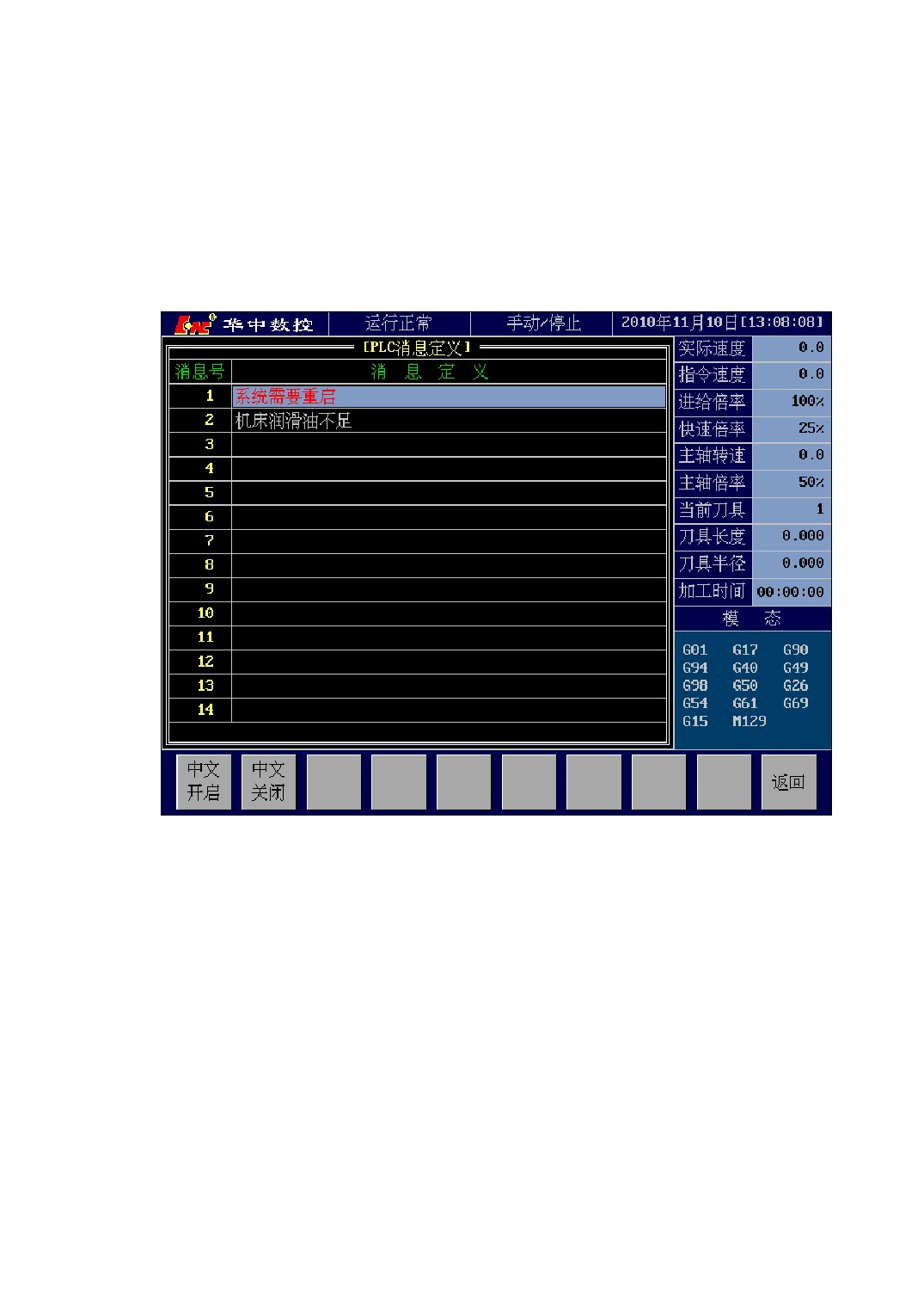
PLC message definition is shown as Figure 7-21. In the definition list of PLC
message, the left is PLC message number which is called by the function command
WMSG; the right is message content which is defined by PLC message number.
If the function command WMSG in PLC is triggered, The title bar will display the
content defined by the message number which WMSG appoints to.
Figure 7-21 PLC Message Definition Interface
107

8 Rotational Axis Circulatory Function
The rotational axis circulatory function can avoid the coordinate overflow of
rotational axis.
If the rotational axis’s circulatory function is valid, for increment programming
command, the tool will move the degree which specified in the command; for absolute
value command, the disposal process of CNC is:
1) Round the command coordinate of programme by the degree of a rotation
(namely convert the coordinate value into 0~360° );
2) If you have not specified that selecting the shortest path, the direction of tool
motion is confirmed by the relationship between the converted target location
and current location: if target location is less than current location, the tool will
move in negative direction; if target location is greater than current location, the
tool will move in positive direction;
3) If have specified that selecting the shortest path, the tool will move to the target
location in the direction of the shortest path.
the rotational axis’s circulatory function is set by parameter P1005(if P1005=1,
enable circulatory function is open; if P1005=0, circulatory function is closed).
The selection of the shortest path is set by parameter P1006(if P1006=1, select the
shortest path; if P1006=0, not select the shortest path). The selection of the shortest
path is valid only when the circulatory function is open.
Demonstration
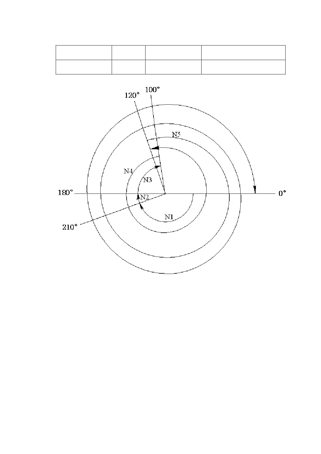
Assume A-axis is a rotational axis, and the amount of movement for each rotation is
360°.Open the rotational axis’s circulatory function(P1005=1), and set as selecting the
shortest path(P1006=1). When execute the following program, A-axis’s motion is shown
as Table-1 and Figure 8-1.
Table-1 rotational axis circulatory function demonstration
Sequence
absolute coordinate value
G90 A0;
Actual movement
number
after motion is finished
N1 G90 A-150.0;
N1
-150°
210
N2 G90 A540.0;
N2
-30°
180
N3 G90 A-620.0;
N3
-80°
100
108
N4 G91 A380.0;
N4
+380°
120
N5 G91 A-840.0;
N5
-840°
0
Figure 8-1 Rotational Axis Circulatory Function Demonstration
109
9 Spindle Gear Control
9.1 Method of Spindle Gear Control
To meet the needs of machining, spindle needs to shift gear control some times.
System supports 5 levels variable speed control of spindle at most——A gear, B
gear, C gear, D gear and E gear. System doesn’t set the range of each gear’s high\low
rotational speed by itself. User can set each gear’s rotational speed range by parameter.
The spindle gear control is carried out by setting system parameters and
programming PLC program.
1、 The parameters about spindle gear control
1) Spindle’s each gear rotational speed range setting
Spindle’s each gear rotational speed range setting is used to plot out the shifting
range of spindle’s each gear. After rotational speed range setting, when system give
spindle rotational command, system will automatically select the corresponding
spindle gear accroding to rotational speed range setting.
P0351: Spindle A gear minimum rotational speed
P0352: Spindle A gear maximum rotational speed
P0353: Spindle B gear minimum rotational speed
P0354: Spindle B gear maximum rotational speed
P0355: Spindle C gear minimum rotational speed
P0356: Spindle C gear maximum rotational speed
P0357: Spindle D gear minimum rotational speed
P0358: Spindle D gear maximum rotational speed
P0359: Spindle E gear minimum rotational speed
P0360: Spindle E gear maximum rotational speed
2) Spindle’s each gear feedback override
If the rotational speed which spindle feeds back is not the same as the actual
rotational speed, you can amend it by spindle feedback override.
P0362: Spindle A gear feedback override
P0363: Spindle B gear feedback override
P0364: Spindle C gear feedback override
P0365: Spindle D gear feedback override
P0366: Spindle E gear feedback override
110

3) Spindle’s each gear reduction ratio
If spindle’s actual rotational speed is not the same as the instruction rotational
speed, an insure spindle’s other parameters setting correctness, then you can amend
it by modifying each gear reduction ratio.
P0371: Spindle A gear reduction ratio
P0372: Spindle B gear reduction ratio
P0373: Spindle C gear reduction ratio
P0374: Spindle D gear reduction ratio
P0375: Spindle E gear reduction ratio
4) Spindle gear shifting rotational speed
In order to finish the process of gear shifting all right, spindle usually turn at a
low speed in the process of gear shifting. This parameter is used to set spindle’s
rotational speed in the process of gear shifting.
P0380: Spindle gear shifting rotational speed
Note
You can’t set the gear shifting speed too high, or else may damage machine.
5) Spindle gear shifting retry delay time
This parameter is used as the time interval from spindle gear shifting is failure
to the next gear shifting retry.
P0381: Spindle gear shifting retry delay time(millisecond)
6) Spindle gear shifting retry count
When spindle shifts gear and retry this parameter count, but still not successful,
then give an alarm: Spindle gear shifting is failure.
2、 PLC signal about spindle gear control
System side input signal:F12.4: Spindle change for A gear startup signal
F12.5: Spindle change for B gear startup signal
F12.6: Spindle change for C gear startup signal
F12.7: Spindle change for D gear startup signal
F13.0: Spindle change for E gear startup signal
System side output signal: G20.0: Spindle A gear arrival signal
111
G20.1: Spindle B gear arrival signal
G20.2: Spindle C gear arrival signal
G20.3: Spindle D gear arrival signal
G20.4: Spindle E gear arrival signal
9.2 Spindle Gear Control Demonstration
For example: according to the need of machine design, spindle shifting range is(gear
shifting speed is 10 r/min):
1)
Low gear 0~880 r/min, reduction ratio 10.52, feedback override 1.0, gear shifting
signal Y02.0, arrival signal X04.0;
2)
Mid gear 881~2200 r/min, reduction ratio 5.04, feedback override 1.1, gear shifting
signal Y02.1, arrival signal X04.1;
3)
High gear 2201~4000 r/min, reduction ratio 1.01, feedback override 1.2, gear
shifting signal Y02.2, arrival signal X04.2.
The demonstration use A, B, C gears to control low, mid, high gear, you can also use
the others gear to control, just need to ensure that each parameter and ladder diagram
signal are the same when used.
The process of spindle gears control setting includes the following steps:
1)
Set spindle shifting range. According to the forementioned instance, set:
P0351(Spindle A gear minimum rotational speed) = 0
P0352(Spindle A gear maximum rotational speed) = 880
P0353(Spindle B gear minimum rotational speed)= 881
P0354(Spindle B gear maximum rotational speed) = 2200
P0355(Spindle C gear minimum rotational speed)= 2201
P0356(Spindle C gear maximum rotational speed) = 4000
The minimum, maximum rotational speed of unused D, E gears are set as 0.
2)
Set each gear feedback override
P0362(Spindle A gear feedback override) = 1.0
P0363(Spindle B gear feedback override) = 1.1
P0364(Spindle C gear feedback override) = 1.2
The feedback override of unused D, E gears are set as 0.
112
3)
Set each gear reduction ratio
P0371(Spindle A gear reduction ratio)= 10.52
P0372(Spindle B gear reduction ratio)= 5.04
P0373(Spindle C gear reduction ratio)= 1.01
The reduction ratio of unused D, E gears are set as 0.
4)
Set spindle gear shifting rotational speed
P0380(spindle gear shifting rotational speed) = 10
5)
Set spindle gear shifting retry delay time(millisecond)
P0381(spindle gear shifting retry delay time)= 5000
6)
Set spindle gear shifting retry count
P0382(Spindle gear shifting retry count) = 3
7)
Programming PLC program
According to the forementioned instance, programming PLC program.
X04.0---------------------------------------------------------( ) G20.0
X04.1---------------------------------------------------------( ) G20.1
X04.2----------------------------------------------------------( ) G20.2
F12.4-----------------------------------------------------------( ) Y02.0
F12.5-----------------------------------------------------------( ) Y02.1
F12.6-----------------------------------------------------------( ) Y02.2
113