HNC-08M CNC SYSTEM CNC Milling System. Operation Manual (V1.22 2011/01) - page 3
5.4 Graphics Parameter
5.4.1 Graphics Zoom Coefficient
The act machining track can be displayed by augmenting or minishing, and the
multiple of augmenting or minishing is the graphics’s zoom coeffcient. The zoom
coefficient >1, the graphics will be augmented; the zoom coefficient <1, the graphics
will be minished; the zoom coefficient =1, the graphics will not be zoom.
The graphics zoom coefficient is set by the following parameter:
P0181: the XY plane’s zoom coefficient in graphics mode
P0182: the YZ plane’s zoom coefficient in graphics mode
P0183: the XZ plane’s zoom coefficient in graphics mode
P0184: the XYZ three-dimension strack’s zoom coefficient in graphics mode
In the Graphics interface, press [ZMUP]、[ZMDW] or [ZORG] menu to zoom the
display graphics. During the program running, if you change the zoom coefficient, the
graphics of the previous zoom coefficient displayed will be cleared out.
5.4.2 Workpiece Size Range
The workpiece size range of which this system can display is (take the workpiece
coordinate system as center, the zoom coefficient =1):
XY plane:
-320mm<X≤320mm,-240mm<Y≤240mm
YZ plane:
-320mm<Y≤320mm,-240mm<Z≤240mm
XZ plane:
-320mm<X≤320mm,-240mm<Z≤240mm
XYZ space:
-320mm<X≤320mm, -240/cos(45º) mm<Y≤240/cos(45º) mm,
-240mm<Z≤240mm,
If the workpiece size goes beyond the display range, the outsides will can not
display. Then you can minish the zoom coefficient to display the minished graphics.
Note:
If the workpiece machining track is in the display size range, but for the limit of
graphics window size, the display may be incomplete. Then press [LMOV]、
[RMOV]、[UMOV] and [DMOV] to adjust the display positon of the graphics in
the window to let the outside parts be visible.
54
5.5 Speed Curve Display
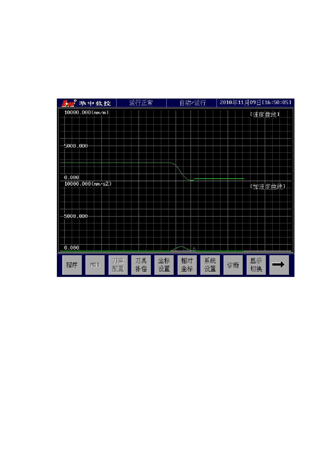
Display the speed and acceleration in the process of machining, and examine the
speed change of the machine tool, as Figure 5-2 shown.
Figure 5-2 Curve Of Speed And Acceleration
The parameter about speed and acceleration curve display is:
P0187 Whether display the speed curve or not [1-show; 0-no show]
Whether display the speed curve interface by seting the [VSWT]menu.
P0188 The maximum of speed curve
Set the upper limit of “speed curve” in speed curve interface displayed, the
unit is (mm/m)
P0189 The maximum of acceleration curve
Set the upper limit of “acceleration curve” in speed curve interface displayed,
the unit is (mm/s2)
P0190 The type of displayed curve [0-instruction curve; 1-actual curve]
Set the speed curve as instruction speed’s or actual feedback speed’s in speed
curve interface displayed.
55
6 Data Input
The system data input mainly includes:
¾ Tool Magazine Configuration
¾ Tool compensation
¾ Coordinate system Setting
¾ Parameter Setting
¾ Axis Configuration
¾ M code’s definition and extension
¾ System Alarm’s definition and extension
¾ Authority Management
¾ Macro Variable modification
6.1 Tool Magazine Configuration
The tool magazine configuration table is used to configure the tool number on each
tool position in tool magazine and the table’s correlative parameter.
Starting Address of Tool Magazine Table: The tool magazine table is stored into
PLC data table. This configuration item is used to set the starting address of tool
magazine table in the data table.It is the reference of parameter P0196, means its
modification and the P0196 parameter modification are equivalent.
Tool Amount: Set the tool amount what tool magazine can store.This configuration
item is the reference of parameter P0196, means its modification and the P0196
parameter modification are equivalent.
Current Tool Number: Set the tool number which is hold on the spindle. This
configuration item is the reference of the D045 in data table.
Current Tool Position Number: Set the tool position number which is on the tool
change position in tool magazine. The item is the reference of the D044 in data table.
Tool Number: Set the tool sequence number which is hold on each tool position in
tool magazine.
The tool magazine table’s relative address is:
Tool magazine table first address = Tool magazine table starting address set value
56
Tool magazine table tail address = Tool magazine table starting address +Tool amount-1
Tool position address = Tool magazine table starting address +Tool position number-1
The address range of nonvolatile storage location in data table is D000~D399. So
the tool magazine table tail address should be limited to 399,or else some errors occur.
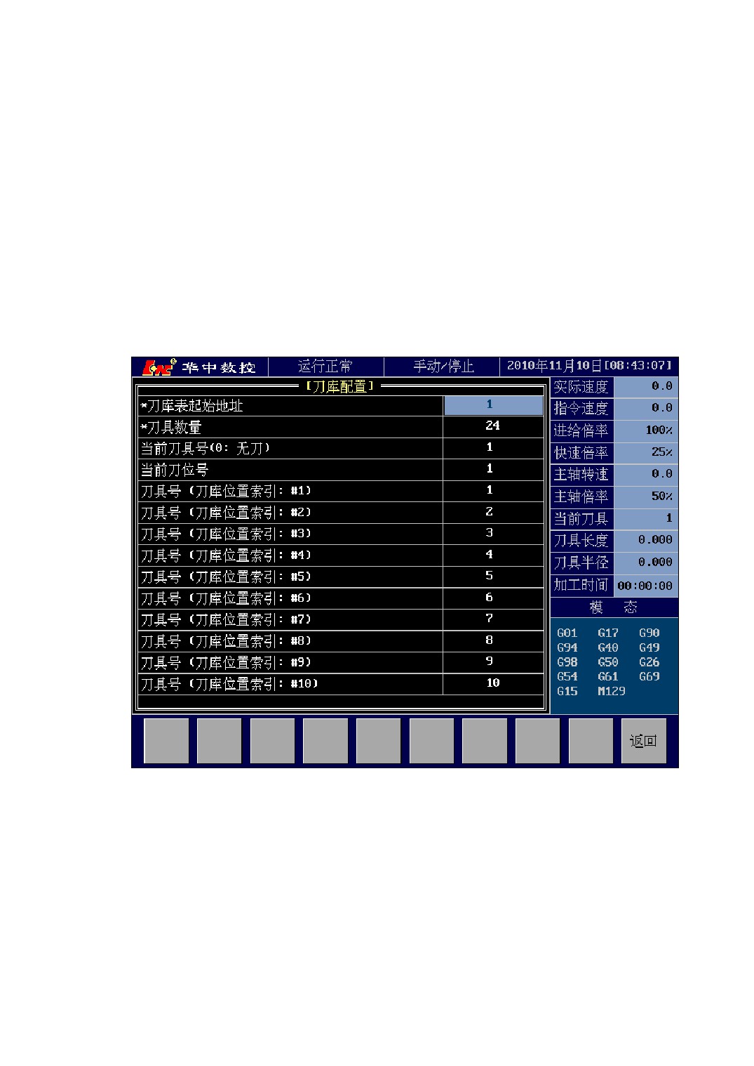
Method of entering into tool magazine configuration interface: [\] → [MAGT]
The interface is shown as figureFigure 6-1. The item which has “*” in front needs
machine tool class or above power that can be modified.
Figure 6-1 Tool Magazine Configuration Interface
57
6.2 Tool Compensation
6.2.1 Summarize
The setting parameters of tool compensation include:
Tool Length: The length offset by contrasting to the reference tool.
Generally, there is a reference tool in the tool magazine whose length
is set to 0. The other tools’ length value is the length offset relatives to
the reference tool.
Tool Radius: The radius of the tool’s cutting part.
Tool Wear: The tool used for a period of time will have a certain degree of wear
and tear, the parameter is used as a correction when system executes the
tool length compensation.
The actual compensation value = tool length - Tool Wear.
6.2.2 Enter the Tool Compensation Table Interface
Method of entering the tool compensation interface: [\] → [OFST]
The tool compensation table interface is shown as figure 6-2:
58
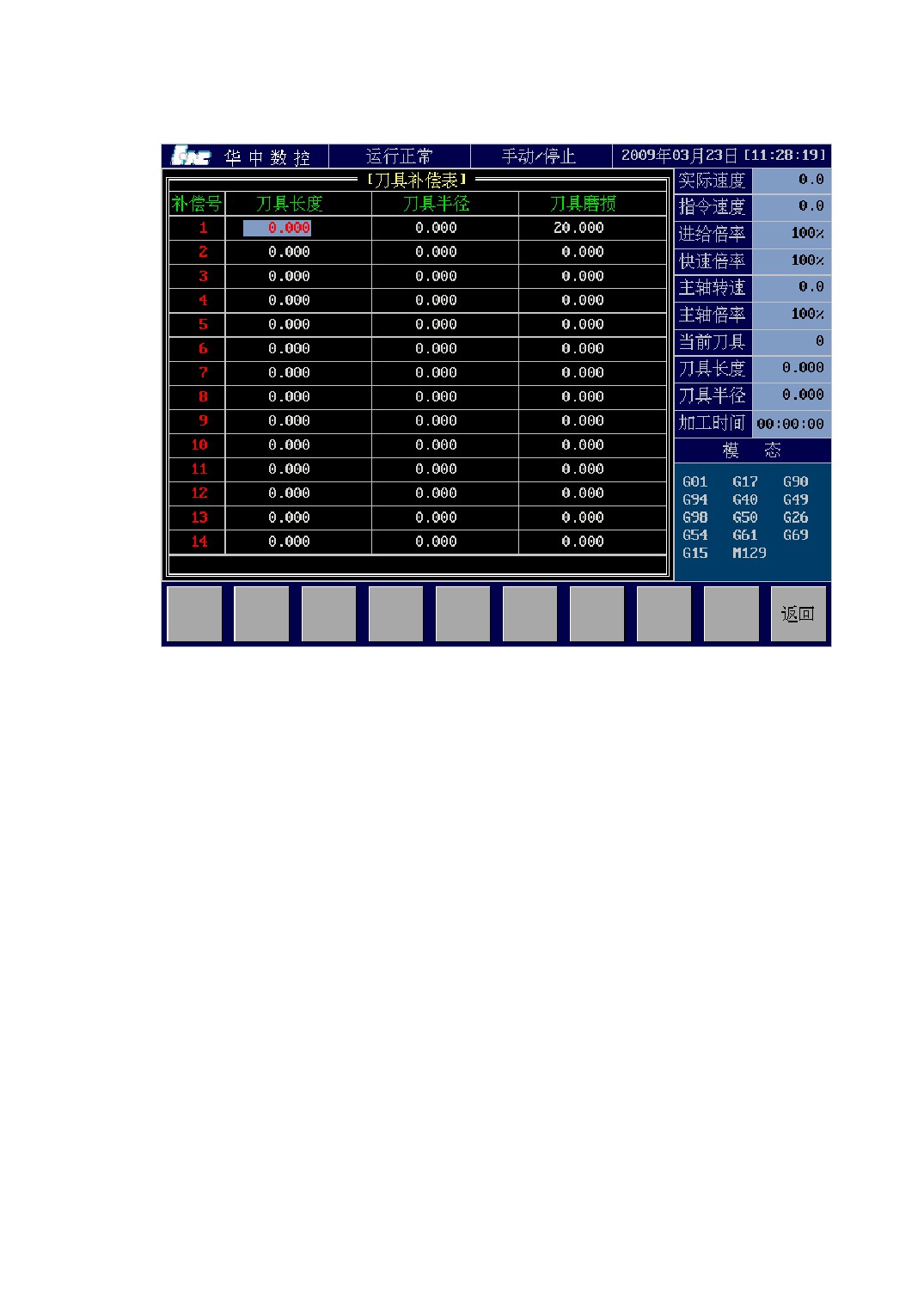
Figure 6-2 Tool Parameter Table Interface
6.2.3 Method of Tool Compensation Parameter Setting
Method of tool parameter modification:
1) After entering the tool compentation management interface, press the [↑]、[↓] or
[PageUp]、[PageDown] keys to select the parameter item needed to set.
2) Press [Enter] key to confirm the selected or direct input a tool parameter, then
a input box will pop up above the selected item (as figure 6-3 shown);
3) Input a new parameter in the pop-up input box and press the [Enter] key to
confirm input. After confirmed, the input box will disappear, and the selected
parameter item’s value will update as the new input value;
59
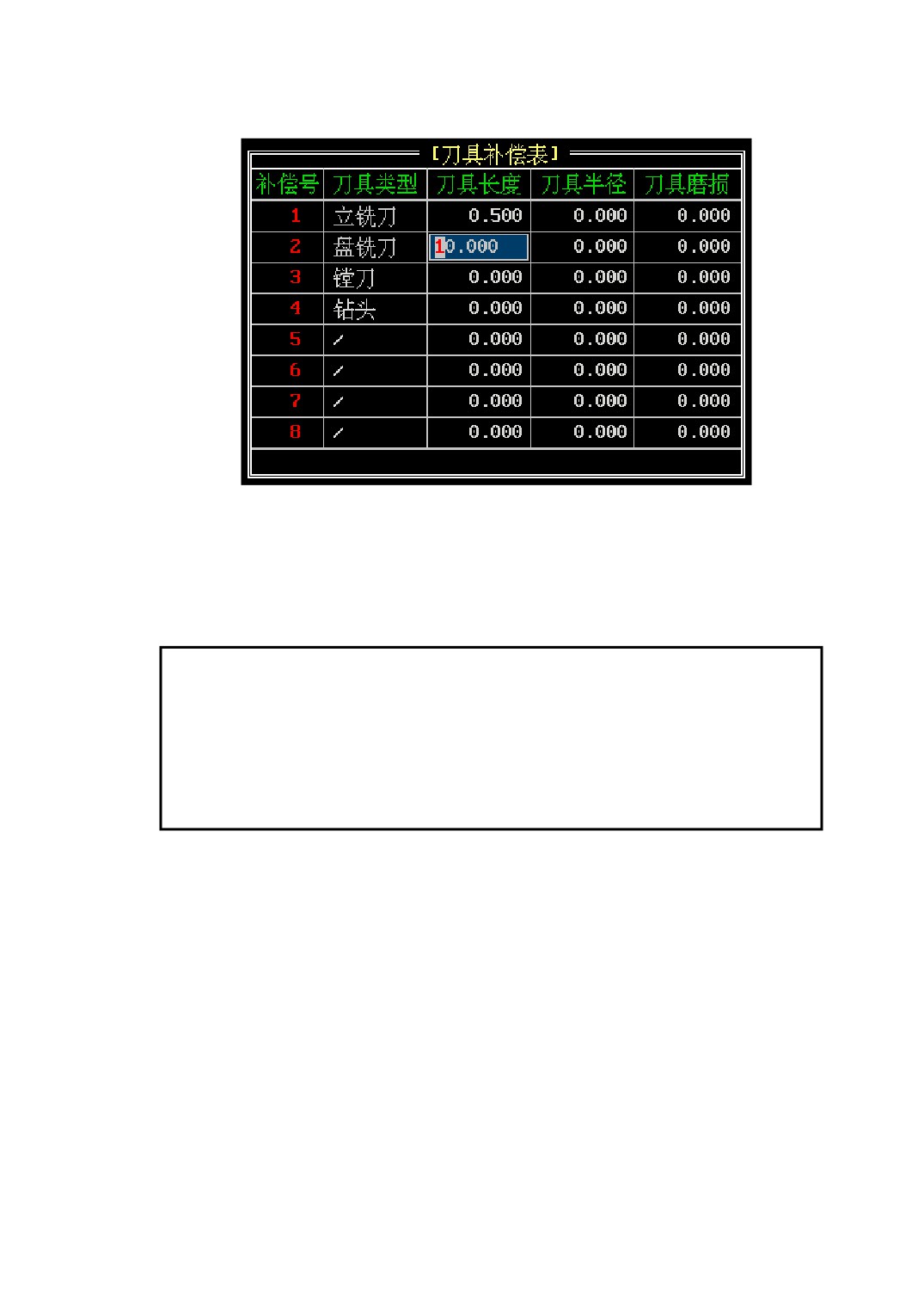
Figure 6-3 Tool Parameter Input
If the input tool compensation value is the Z value in the current machine tool
coordinate system, the machine tool coordinate value can be input into the selected
item by pressing [TCUR] menu.
Note:
1) Press [Enter] key to make it valid after input a new parameter in the input box;
2) CNC system will save the new parameters when the compensation setting
window is closed.
60
6.3 Coordinate System Setting
6.3.1 Coordinate System Summary
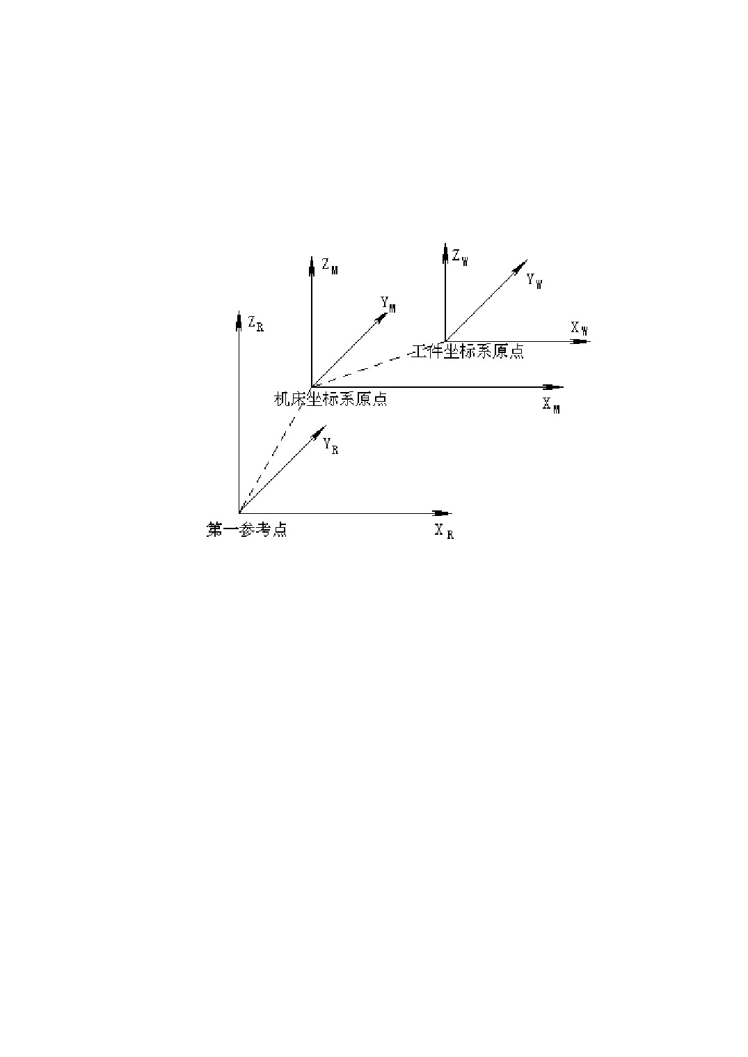
Figure 6-4 Sketch map of coordinate system
1) Reference Coordinate System
Reference point is a fixure on the machine tool. There are four reference points in all-
the first reference point, the second reference point, the third reference point and the
fourth reference point. The first reference point’s position is determined by a mechanical
switch while the others’ positions are specified by the system parameters.
Each reference point’s position parameters are as follows:
The first reference point:
P0081: X-axis first reference point
P0082: Y-axis first reference point
P0083: Z-axis first reference point
P0084: Fourth-axis first reference point
P0085: Fifth-axis first reference point
P0086: Sixth-axis first reference point
P0087: Seventh-axis first reference point
P0088: Eighth-axis first reference point
61
The second reference point:
P0091: X-axis second reference point
P0092: Y-axis second reference point
P0093: Z-axis second reference point
P0094: Fourth -axis second reference point
P0095: Fifth-axis second reference point
P0096: Sixth-axis second reference point
P0097: Seventh-axis second reference point
P0098: Eighth-axis second reference point
The third reference point:
P0101: X-axis third reference point
P0102: Y-axis third reference point
P0103: Z-axis third reference point
P0104: Fourth-axis third reference point
P0105: Fifth-axis third reference point
P0106: Sixth-axis third reference point
P0107: Seventh-axis third reference point
P0108: Eighth-axis third reference point
The fourth reference point:
P0111: X-axis fourth reference point
P0112: Y-axis fourth reference point
P0113: Z-axis fourth reference point
P0114: Fourth-axis fourth reference point
P0115: Fifth-axis fourth reference point
P0116: Sixth-axis fourth reference point
P0117: Seventh-axis fourth reference point
P0118: Eighth-axis fourth reference point
2) Machine tool Coordinate System
Machine tool coordinate system is the basical coordinate system of machine control.
And it is also the reference of coordinate system transformation during the machining.
The zero position of machine tool coordinate system is determined by the position
parameter of the first reference point.
62
The first reference point’s position on machine tool is determined by the mechanical
switch. If the mechanical switch is fixed, the first reference point’s position is fixed. Due
to reference point position parameter settings are in the machine tool coordinate system,
when the first reference point’s position parameters change, its physical location does
not change and the actual change is the zero position of machine tool coordinate system.
After Power is on, executing returning the reference point in manual mode can
establish the machine tool coordinate system. Once established, it will remain the same
until cut off the power.
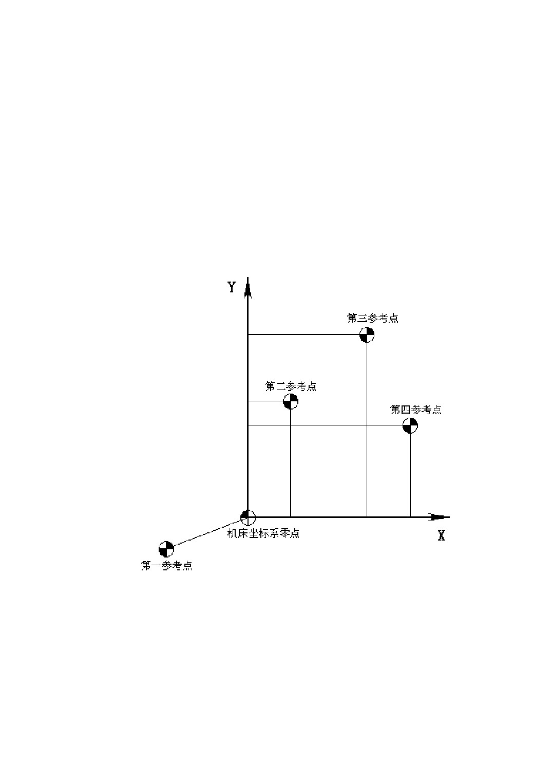
the position relationship between machine tool coordinate system and each reference
points is shown as figure 6-5.
Figure 6-5 Position Relationship between Machine Tool Coordinate System and
Reference Points
3) Workpiece Coordinate System
The coordinate system which is used for programing machining program is workpiece
coordinate system.
System stores six workpiece coordinate system for selecting. The zero position of
63
workpiece coordinate system is set by the parameter, and the set value is the offset of
workpiece coordinate system’s zero relative to machine tool coordinate system’s zero.
The first workpiece coordinate system (G54) will be selected automatically when
power is on.
The first workpiece coordinate system (G54):
P1021: X-axis zero point of the first workpiece coordinate system (G54.X)
P1022: Y-axis zero point of the first workpiece coordinate system (G54.Y)
P1023: Z-axis zero point of the first workpiece coordinate system (G54.Z)
P1024: Fourth-axis zero point of the first workpiece coordinate system (G54.4)
P1025: Fifth-axis zero point of the first workpiece coordinate system (G54.5)
P1026: Sixth-axis zero point of the first workpiece coordinate system (G54.6)
P1027: Seventh-axis zero point of the first workpiece coordinate system (G54.7)
P1028: Eighth-axis zero point of the first workpiece coordinate system (G54.8)
The second workpiece coordinate system (G55):
P1031: X-axis zero point of the second workpiece coordinate system (G55.X)
P1032: Y-axis zero point of the second workpiece coordinate system (G55.Y)
P1033: Z-axis zero point of the second workpiece coordinate system (G55.Z)
P1034: Fourth-axis zero point of the second workpiece coordinate system (G55.4)
P1035: Fifth-axis zero point of the second workpiece coordinate system (G55.5)
P1036: Sixth-axis zero point of the second workpiece coordinate system (G55.6)
P1037:Seventh-axis zero point of the second workpiece coordinate system (G55.7)
P1038: Eighth-axis zero point of the second workpiece coordinate system (G55.8)
The third workpiece coordinate system (G56):
P1041: X-axis zero point of the third workpiece coordinate system (G56.X)
P1042: Y-axis zero point of the third workpiece coordinate system (G56.Y)
P1043: Z-axis zero point of the third workpiece coordinate system (G56.Z)
P1044: Fourth-axis zero point of the third workpiece coordinate system (G56.4)
64
P1045: Fifth-axis zero point of the third workpiece coordinate system (G56.5)
P1046: Sixth-axis zero point of the third workpiece coordinate system (G56.6)
P1047: Seventh-axis zero point of the third workpiece coordinate system (G56.7)
P1048: Eighth-axis zero point of the third workpiece coordinate system (G56.8)
The fourth workpiece coordinate system (G57):
P1051: X-axis zero point of the fourth workpiece coordinate system (G57.X)
P1052: Y-axis zero point of the fourth workpiece coordinate system (G57.Y)
P1053: Z-axis zero point of the fourth workpiece coordinate system (G57.Z)
P1054: Fourth-axis zero point of the fourth workpiece coordinate system (G57.4)
P1055: Fifth-axis zero point of the fourth workpiece coordinate system (G57.5)
P1056: Sixth-axis zero point of the fourth workpiece coordinate system (G57.6)
P1057: Seventh-axis zero point of the fourth workpiece coordinate system (G57.7)
P1058: Eighth-axis zero point of the fourth workpiece coordinate system (G57.8)
The fifth workpiece coordinate system (G58):
P1061: X-axis zero point of the fifth workpiece coordinate system (G58.X)
P1062: Y-axis zero point of the fifth workpiece coordinate system (G58.Y)
P1063: Z-axis zero point of the fifth workpiece coordinate system (G58.Z)
P1064: Fourth-axis zero point of the fifth workpiece coordinate system (G58.4)
P1065: Fifth-axis zero point of the fifth workpiece coordinate system (G58.5)
P1066: Sixth-axis zero point of the fifth workpiece coordinate system (G58.6)
P1067: Seventh-axis zero point of the fifth workpiece coordinate system (G58.7)
P1068: Eighth-axis zero point of the fifth workpiece coordinate system (G58.8)
The sixth workpiece coordinate system (G59):
P1071: X-axis zero point of the sixth workpiece coordinate system (G59.X)
P1072: Y-axis zero point of the sixth workpiece coordinate system (G59.Y)
65
P1073: Z-axis zero point of the sixth workpiece coordinate system (G59.Z)
P1074: Fourth-axis zero point of the sixth workpiece coordinate system (G59.4)
P1075: Fifth-axis zero point of the sixth workpiece coordinate system (G59.5)
P1076: Sixth-axis zero point of the sixth workpiece coordinate system (G59.6)
P1077: Seventh-axis zero point of the sixth workpiece coordinate system (G59.7)
P1078: Eighth-axis zero point of the sixth workpiece coordinate system (G59.8)
6.3.2 Workpiece Coordinate System Setting
Two methods to set workpiece coordinate system:
1) Directly set the corresponding parameter of coordinate system’s zero point in the
system parameters table;
2) Quickly set the workpiece coordinate system in its setting interface.
Refer to the "System parameter setting" section for the first setting method. This
section only introduces the second setting method. The second method is the same as the
first in essence, which is also used to set workpiece coordinate system’s parameters
mentioned above, the difference is that it is operated in the specialized interface.
Method of entering into the setting interface: [\] → [SCRD]
The workpiece coordinate system setting interface is shown as figure 6-6:
66
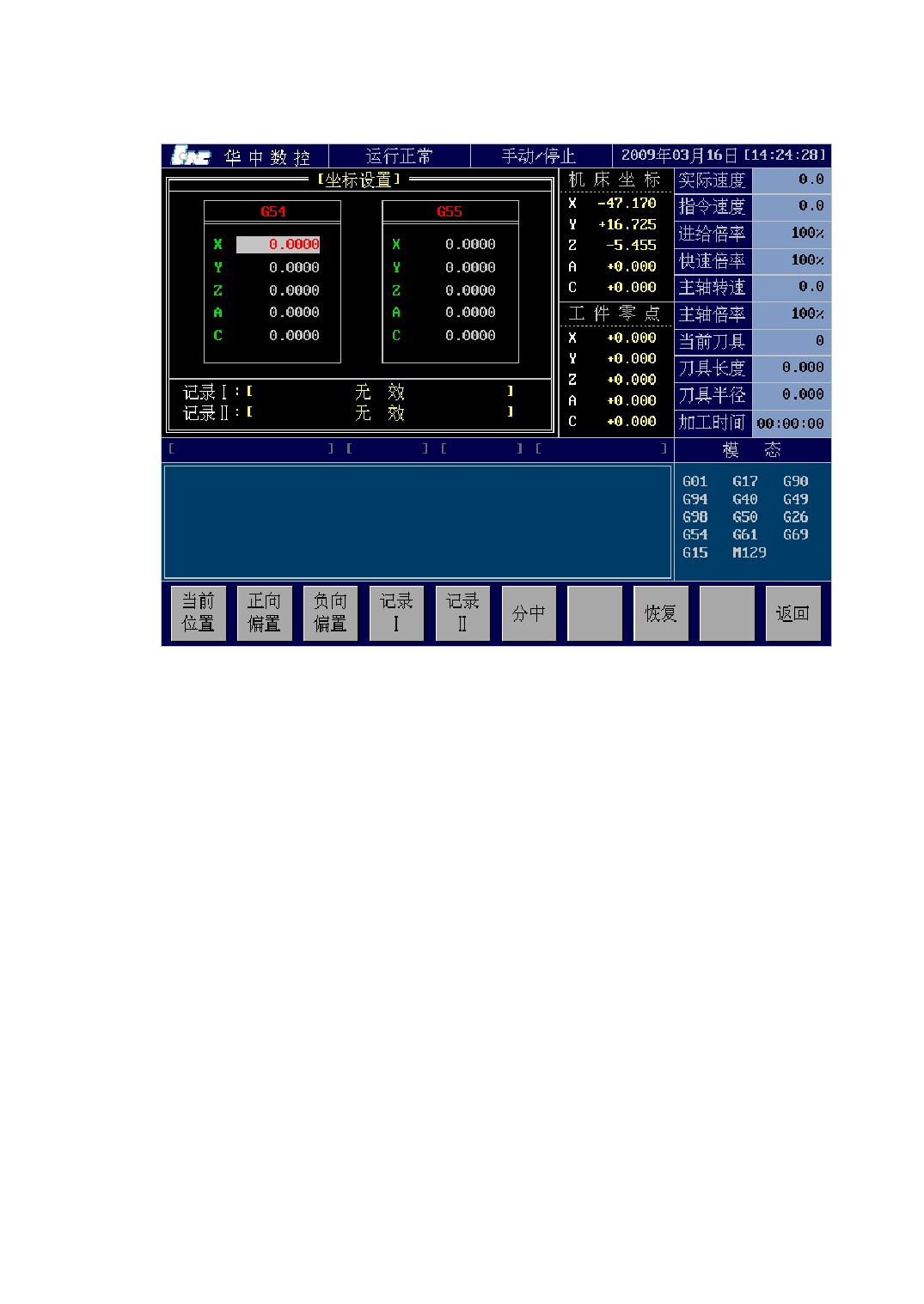
Figure 6-6 Workpiece Coordinate System Setting Interface
Sequence of workpiece coordinate system setting:
1) Use [→]、[←] or [PageUp]、[PageDown] keys to select the workpiece coordinate
system (G54~G59, external zero offset);
2) After the workpiece coordinate system selected, use [↑]、[↓] keys to select the set
coordinate axis;
3) After the coordinate axis selected, press [Enter] key or direct input a coordinate
value, then it will pup up a input box on the selected coordinate axis;
4) Enter a new workpiece coordinate zero offset into the pop-up input box. If the input
zero position is the actual location of the current axis, you can press [CCUR] key to
automatically input the machine tool coordinate value of the axis’s current location
as the zero offset value of the axis’s workpiece coordinate;
5) Press [ENTER] key to confirm the input. Then the input box disappears and the new
input value is displayed as the axis’s coordinates offset value.
6) The external zero offset is the shortcut setting of the parameter P1220~P1227.
Function menu of coordinates sets:
[CCUR]: The machine tool coordinate value of the coordinate axis’s location is used as
67
the workpiece zero location, and automatically input into the corresponding
coordinate parameter. The menu is used in conjunction with the cursor, only
operate to the coordinate axis selected by the current cursor. For example, if
the cursor is displayed in the G56 Y-axis, and then press [CCUR] key, the
machine tool coordinate value of the Y-axis’s location will be used as the G56
Y-axis offset value and automatically input into the G56 Y-axis parameter.
[ADD_]: Move the workpiece zero position of the coordinate axis selected by the current
cursor in the positive direction for some distance. After input offset distance,
the system automatically calculates the new zero position and stores it into the
corresponding coordinate axis’s zero parameters.
[DEC_]: Move the workpiece zero position of the coordinate axis selected by the current
cursor in the negative direction for some distance. After input offset distance,
the system automatically calculates the new zero position and stores it into the
corresponding coordinate axis’s zero parameters.
[REC1]: Store the position coordinate of the current machine tool into the recordⅠfor
mid-division or difference-evaluation used.
[REC2]: Store the position coordinate of the current machine tool into the recordⅡfor
mid-division or difference-evaluation used.
[MIDP]: Mid-division function use the average value(midpoint) of the coordinate value
in the recordⅠand the coordinate value in the recordⅡ as the new coordinate
zero and automatically store into the coordinate system selected by the cursor.
[DECP]: Difference-evaluation function use the difference value of the coordinate value
in the recordⅡsubtracted from the coordinate value in the recordⅠas the new
coordinate zero and automatically store into the coordinate system selected by
the cursor.
[WRST]:Copy the workpiece zero coordinate in the second assistant window to the
coordinate system which the current cursor locates in.
[RESM]: When the workpiece coordinate system’s zero was modified every time, the
system automatically records the value before changed. Pressing the [RESM]
menu can recover the modified coordinate zero for the old value. But this
function can only recover the last value before changed.
68

6.4 System Parameters Setting
6.4.1 Parameter Classification Explanation
The system parameters of this CNC can be classified three grades according to the
privilege level’s high or low:
1) Systyem Manufacturer Level: This grade parameters belong to the core parameters
which are in connection with system development. Modifying this kinds parameters
may cause system’s abnormal execution, so it needs the highest authority demand.
2) Machine Manufacturer Level: This grade parameters belong to machine tool
configuration parameters, it is modified by machine manufacturer. Its privilege level
take second place.
3) End User Level: This grade parameters are a variety parameter of the end user using.
Its privilege level is the lowest.
In the parameter setting interface, the parameters numbers of system manufacturer
level’s parameters begin with ‘S’, such as S2051; the machine tool manufacturer level’s
parameters begin with ‘M’, such as M0237; the end user level’s parameters begin with
‘U’, such as U1021.
For more details about permission, see the " Authority Management" section.
Mapping table of three grades authority and parameters modified is as follows:
Parameters
System
Machine
Authority
Manufacturer
Manufacturer
End User Parameters
Parameters
Parameters
System Manufacturer
√
√
√
Authority
Machine Manufacturer
×
√
√
Authority
End User Authority
×
×
√
‘√’means this row’s authority can modify this column’s parameters
‘×’means this row’s authority can not modify this column’s parameters
69
6.4.2 Paramter Type
The system paramters are divided into three types:
① Decimal Integer
This kind parameters are decimal integer, not include decimal fraction part. When
you modify them, you can only input the number of 0~9 and the sign of ‘+’ or ‘-’.
In system parameter setting interface, decimal integer paramters are displayed for
five figures.
② Hexadecimal Integer
This kind parameters are hexadecimal integer, not include decimal fraction part.
When you modify them, you can input the number of 0~9 and the six letters of A, B, C,
D, E, F.
In system parameter setting interface, hexadecimal integer paramters are displayed
for five figures.
③ Floating-Point Parameter
This kind parameters are made of a floating point numbers, include integer part and
decimal fraction part. When you modify them, you can input the number of 0~9 and the
characters of ‘+’ , ‘-’or ‘.’.
In system parameter setting interface, floating point paramters are displayed for ten
figures when the parameter value is greater than zero, and displayed for eleven figures
when less than zero(the redundant one used for a minus sign ‘-’ shown), thereinto, the
integer part has five figures and the decimal fraction part has four figures.
6.4.3 Paramter Setting
Operation method of entering into system parameter setting interface:
[\] → [SSET] → [PARA]
The course of system parameter setting is as follows:
1) Enter into the parameter setting window;
2) Select the parameter item: use [↑]、[↓] or [PageUp]、[PageDown] keys to locate the
parameter item which needed modified, or direct locate the needed parameter item
by using search manner.
3) Enter into edit state: After select the item, press [Enter] or direct input parameter
contents, if the current privilege level fill the parameter’s authority demand, it will
70
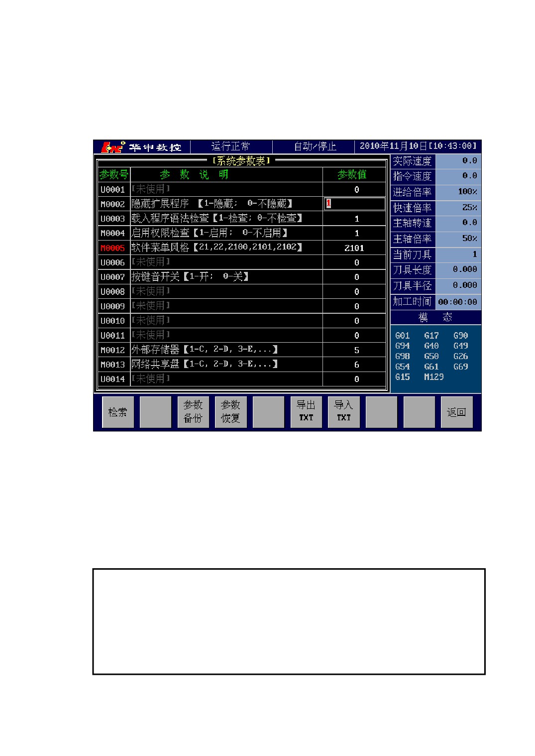
pop up a input box above the selected item (has a cursor twinkle), which can receive
the user input, as figureFigure 6-2 shown;
Figure 6-2
System Parameter Setting
4) Modify the parameter value: Input a new parameter value into the pop-up input box;
5) Confirm the input: After input a new value, you should press [Enter] key again to
confirm the input, then the input box will disappear, and return to the parameter item
selected state;
Note:
1、 After input a new parameter into the input box, you should press [Enter] key to
confirm, then the input parameter can be effective;
2、 CNC system will save the modified parameter when the parameter setting
window is closed.
71
6.4.4 Parameter Searching
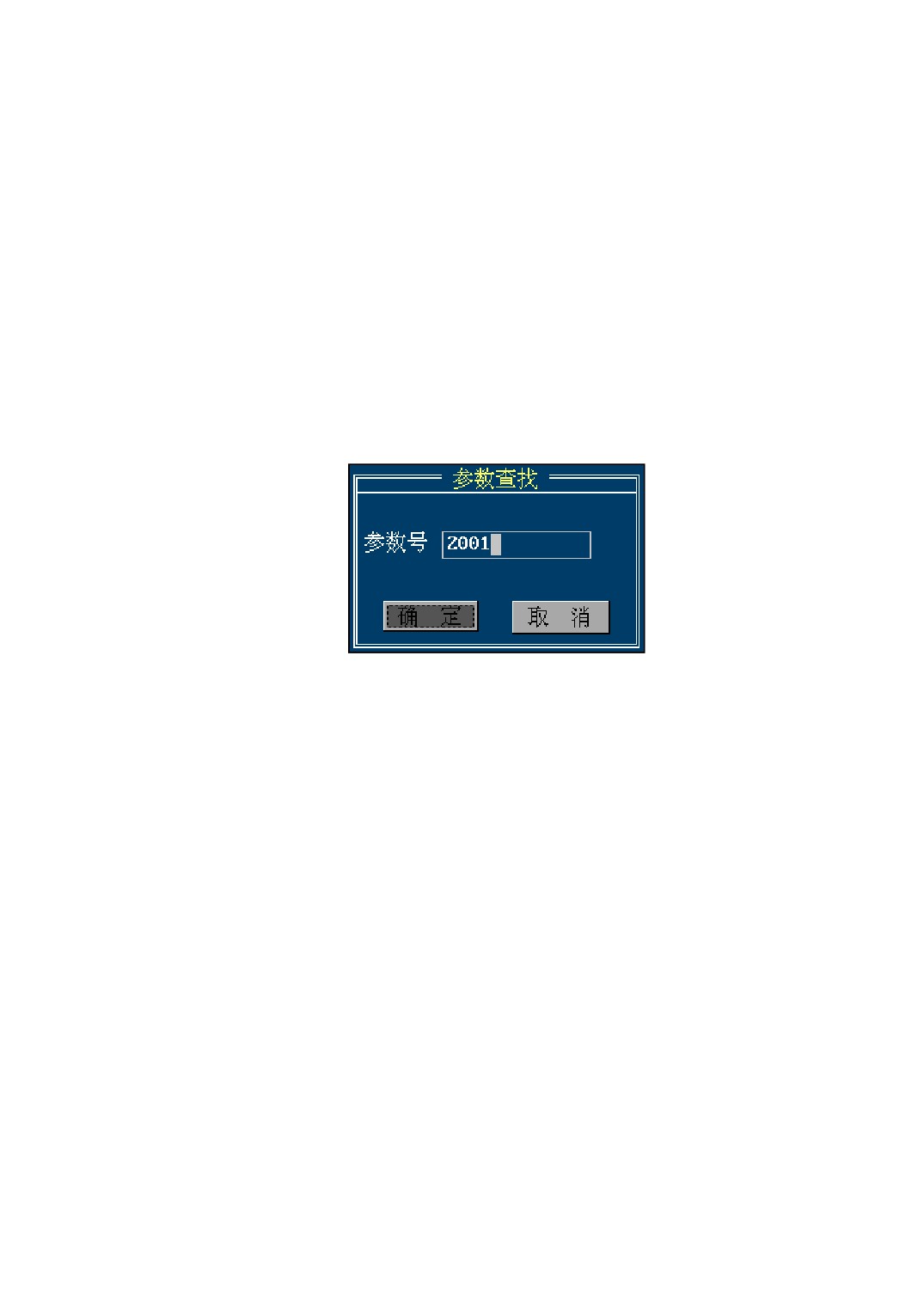
Search the parameter item of the specified parameter number in the parameter table,
and display the searching result as the current selected item. After press the [AFND]
menu, it will pop up a input dialog box, as Figure 6-3 shown. Input the parameter
number for searching in the pop-up input box , select “OK” button or press [Enter] key,
then it will begin to search the specified parameter. If the searching is success, the
parameter window will automatically go to the searched parameter and use the
paramteter as the current cursor selected parameter; If it can’t search the specified
parameter, the title bar will pop up a warning prompt box, as Figure 6-4 shown.
Figure 6-3
Input a Parameter Number for Searching
72
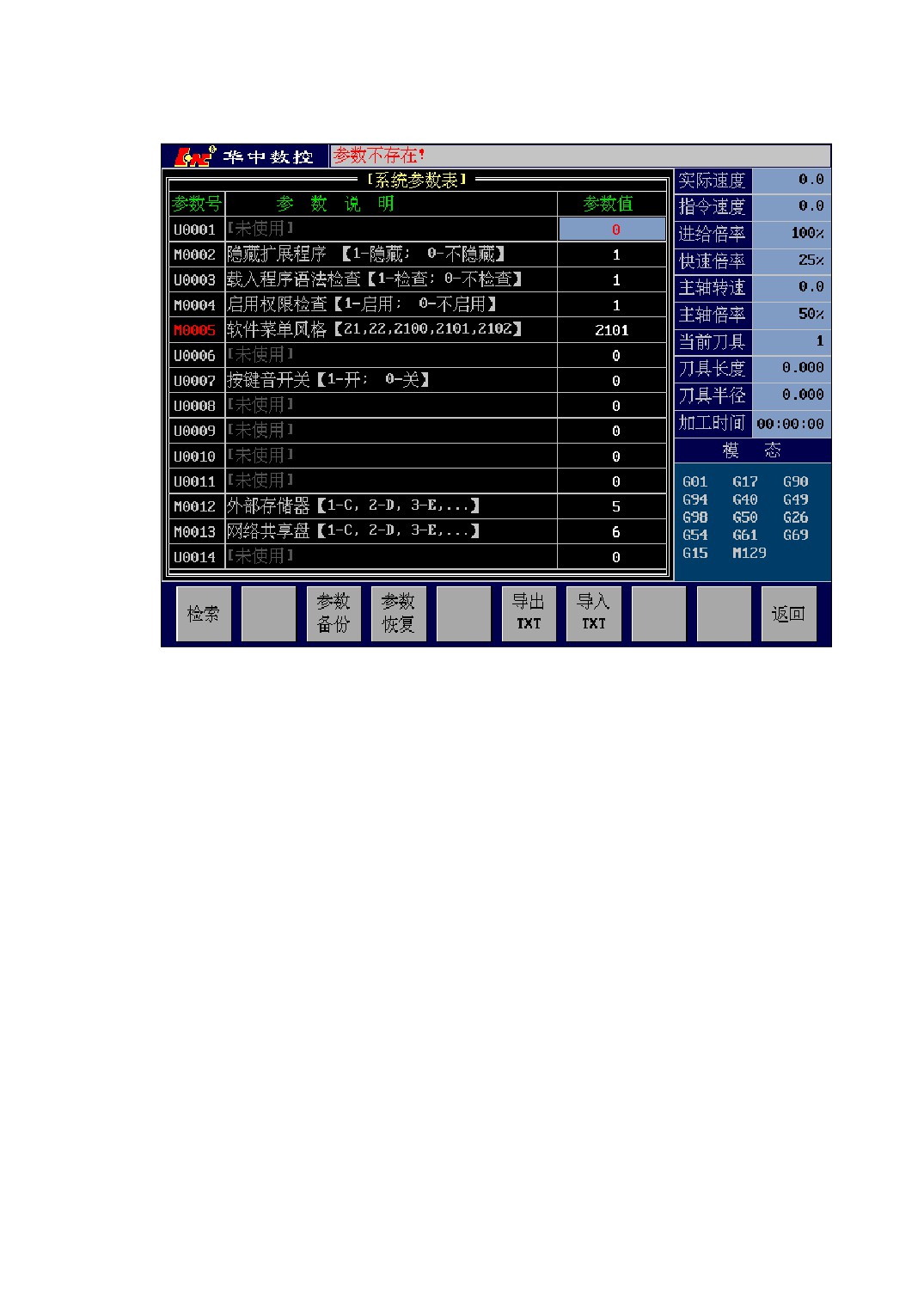
Figure 6-4
Parameter Searching Failure
6.4.5 Parameter’s Backup and Recovery
1、 Parameter Backup
Parameter backup means copy the system parameters and store it into the backup
storage. When needed, it can be recovered to system parameters by using parameter
recovery function. When backup parameters, the path and filename of parameter backup
can be specified by a parameter backup dialog box. If the backup path and filename are
the same, the last time backup will recover the previous backup parameters.
Method of parameter backup: [\] →[SSET] → [PARA] → [ABKP]
And then, specify the path and filename to backup parameters. Finally, press [Enter]
key to confirm.
2、 Parameter Recovery
Parameter recovery means recover the parameter backup file into the system default
parameter file. The recovery operation will cover the original parameter file with the
73
backup file, you should pay attention to when operate.
In the system parameter interface, press [ARSM] menu, input the path and filename
of parameter backup into the parameter recovery dialog, and then press [Enter] key to
confirm, the backup parameter’s recovery is finished.
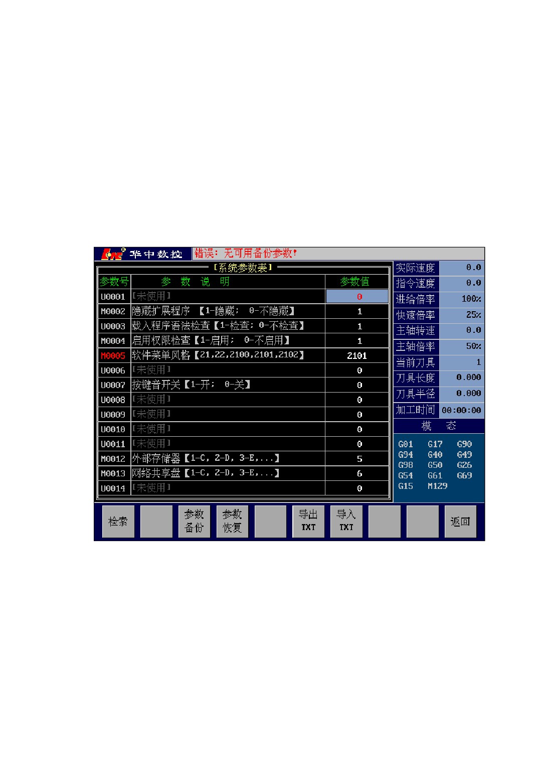
If the path and filename has no backup parameter file which are specified by the
parameter recovery dialog, the title bar will pop up a prompt box, as Figure 6-4 shown.
Method of parameter recovery:[\] →[SSET] → [PARA] → [ARSM]
And then, specify path and filename of the parameter backup. Finally, press [Enter]
key to confirm.
Figure 6-5
No Backup Parameter File
6.4.6 Parameters Export and Import
1、 Parameters Export
Export the parameters in the form of TXT text into the specified path by using
[EXPT] menu.
74
Operation method: [\] →[SSET] → [PARA] →[EXPT]
And then, set the path and filename of export file in the export TXT dialog box.
Finally, press [Enter] key to confirm.
2、 Parameters Import
Import the parameters in the form of TXT text into the system directory by using
[IMPT] menu.
Operation method: [\] →[SSET] → [PARA] →[IMPT]
And then, set the path and filename of import file in the import TXT dialog box.
Finally, press [Enter] key to confirm.
If there is no export parameter file of which filename is specified in the system
directory, the title bar will pop up a prompt box.
6.5 Logic Axis Configuration
This system’s logic axis means the coordinate axis which interpolator supports, the
purpose of logic axis configuration is mapping the logical axis into the specific physical
axis, and control the motor’s running by the physical axis. At present, the interpolator
support eight coordinate axis’s interpolation control at most, so, the CNC system can
collocate eight logical axis at most.
Method of entering into axis configuration interface: [\] →[SSET] → [CHNL]
The axis configuration interface is shown as Figure 6-6.
75
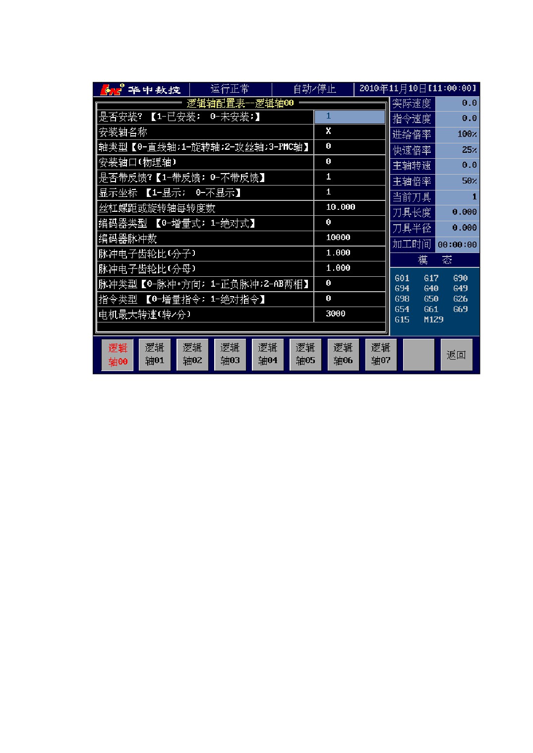
Figure 6-6
Logic Axis Configuration Interface
Contents of logic axis configuration mainly includes several kinds as follows:
1、 Physical axis information
Physical axis information means NC system’s hardware information, includes:
1) Whether to install?: Means whether the logic aixs has the corresponding
physical axis. If the installation symbol is 0, means the logic axis doesn’t
physically assign the actual axis, namely, the logic axis hasn’t been used.
Therefore, when the installation symbol is 0, all of the logic axis’s confiuration
items are invisible ( needn’t configure).
2) Installed axis name: The name of installed physic axis, such as X, Y, Z ect.
3) Axis type: Select the usage type of the axis.
4) Installed axis
(physical): Index of the physical axis which the logic axis
corresponds to.
5) Whether has feedback?: Whether the system deals with the feedback signal
from the coder. If dealing with the feedback signal, set it as 1; or else set as 0.
2、 Display information setting
The parameter of whether display the coordinate axis:
76
Display coordinate: if set as 1, the logic axis’s coordinate will be displayed in all
coordinate display of interface; if set as 0, the logic axis’s coordinate will not be
displayed in all coordinate display of interface;
3、 Machine tool relevant information
For specific machine tool, every axis needs corresponding configuration, includes:
1) Screw-pitch or rotation axis revolutions per degree
2) Coder type
3) Coder pulse number
4) Electron gear ratio
5) Pulse type
6) Instruction type
7) Motor’s maximum revolution
8) Motor’s revolution direction
9) Check whether return the reference point
10) Feedback electron gear ratio
4、 Synchronizing shaft information
Every installed physical axis can be defined a synchronizing shaft. When the
driving shaft moves, the synchronizing shaft move driving shaft in step. If there has
installed a synchronizing shaft, you should define the shaft’s relevant information in
logic configuration, includes:
1) Whether to install synchronizing shaft: If the synchronizing shaft has been
installed, this item is set as 1, or else set as 0;
2) Synchronizing shaft’s installed axis: similar to driving shaft’s installed axis;
3) Synchronizing shaft’s motor reverse: set as 0 or 1, this setting item can change
the diversion turning direction of synchronizing shaft’s motor;
4) Synchronizing shaft’s feedback electron gear ratio;
5) Double-shaft’s acceptable synchronization error: The error which the driving
shaft and driven shaft accept in the process of synchronization, CNC detects the
synchronization error of driving and driven shafts all the time, if the error is
greater than acceptable value, the system will warn and deal with .
6) Synchronization error compensation parameter: The compensation parameter
which is used to compensate synchronization error by system.
77
6.6 M-Code’s Extension Definition
6.6.1 M-Code Summarize
After auxiliary function M-code executed, system will export the specified signal
(high or low level) to the appointed I/O address, you can use this signal to control all
kinds of switches on the machine tool. After M-code executed, CNC will export the
strobe signal R89.0 as 1, but CNC doesn’t see to reset the strobe signal, which is
accomplished by the PLC program of your design.
The following M-codes are in the hands of system inside, you needn’t define them:
M00:Program Pause
M01:Program Optional Stop
M02:When the program is finish, the program will rest on this line.
M03:Spindle Clockwise Rotation
M04:Spindle Counter-clockwise Rotation
M05:Spindle Stop
M30:Program End
M98:Subroutine Call
M99:Subroutine Return
Except the M-codes of system internal processing, you can extend fifty M-codes at
most. For the M-codes of system internal processing, you can also define them for
supplement, the method is the same as extending M-code.
The M-codes of user defined include several factors as follows:
1)
Function Description: Describes the M-code implemented function, eight
characters at most(four Chinese characters);
2)
M-code: Fill in the extended M-code’s name. Such as: M07;
3)
Operation Signal: Specify output signal and address when the M-code executed.
The address only is the system PLC internal relay’s address room R90.x~R99.x
(this address range only can be used for M-code’s extention, the user can’t use it). If
you want to control the other switch, you need put through M-code’s operation
signal to its switch’s signal address in PLC program.
4)
Operation Result: Determine the output which is exported to operation signal is a
high or low level, when M-code executed.
0—export low level
78
1—export high level
5)
Wait Signal: If the M-code has been set a wait signal, and after M-code execution
is finished, the program will pause and don’t continue the following untill the wait
signal become a high level. If the M-code has no wait signal, and after M-code
execution is finished, the program’s pause time is specified by operation delay.
M-code’s wait signal can be a normally open contact or a normally closed contact.
When set as a normally closed contact, add “/” in front of input wait signal.
6)
Operation Delay: Appoint the program’s pause time after M-code execution is
finished, when the time is out, the program will continue to execute downwards. If
set a wait signal, the pause time begins from the time the wait signal become to
high level. The operation delay is set in milliseconds.
7)
Call Program: Specify the extension program name which program calls after the
M-code execution is finished. The specified program must exist in the system’s
extension folder.
The executing flow of user defined M extension code:
1)
If M extension code has “Operation Signal” and “Operation Result”, the system
will transfer “Operation Result” to “Operation Signal” at first, and then enter into
the next step; Or else, direct enter into the next step;
2)
If M extension code has “Wait Signal”, the program will pause to await the
specified “Wait Signal” arrival, after the “Wait Signal” coming, enter into the next
step; If there is no “Wait Signal”, direct enter into the next step;
3)
In this step, program will direct pause for a while which is specified by “Operation
Delay”, in millisecond. If set as 0, it will pause for 0 millisecond. After the delay
time arrives, direct enter into the next step;
4)
If M extension code has “Call Program”, program will call the specified extension
in this step. After the extension execution is finished, M extension code execution is
over; If M extension code has no “Call Program”, the M extension code is over.
6.6.2 M-Code’s Definition and Extension
Method of entering into M-code extension interface: [\] →[SSET] → [MCOD]
M-code extension interface is shown as Figure 6-7.
The item which displays “*” in the window means the parameter item isn’t set
(namely this item is invalidation).
79
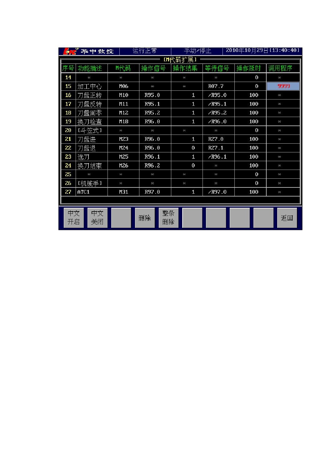
Figure 6-7
M-Code Extension Definition Interface
6.7 System Alarm Definition and Extension
6.7.1 System Alarm Summarize
System alarm has two kinds: the one is system internal alarm, the other is user
defined extension alarm.
1)
System Internal Alarm
This part alarm is defined by CNC system inside, user can not modify.
The alarm number of system internal alarm is No.0~No.399.
2)
User Defined Extension Alarm
User externsion alarm is defined by user, the alarm number is No.400~No.511.
The corresponding input point of every extension alarm is set by user, if the input
point is set as 1, system will give the corresponding alarm information; On the contrary,
if the input signal is 0, system will automatically clean the alarm information out.
80
6.7.2 System Alarm’s Extension
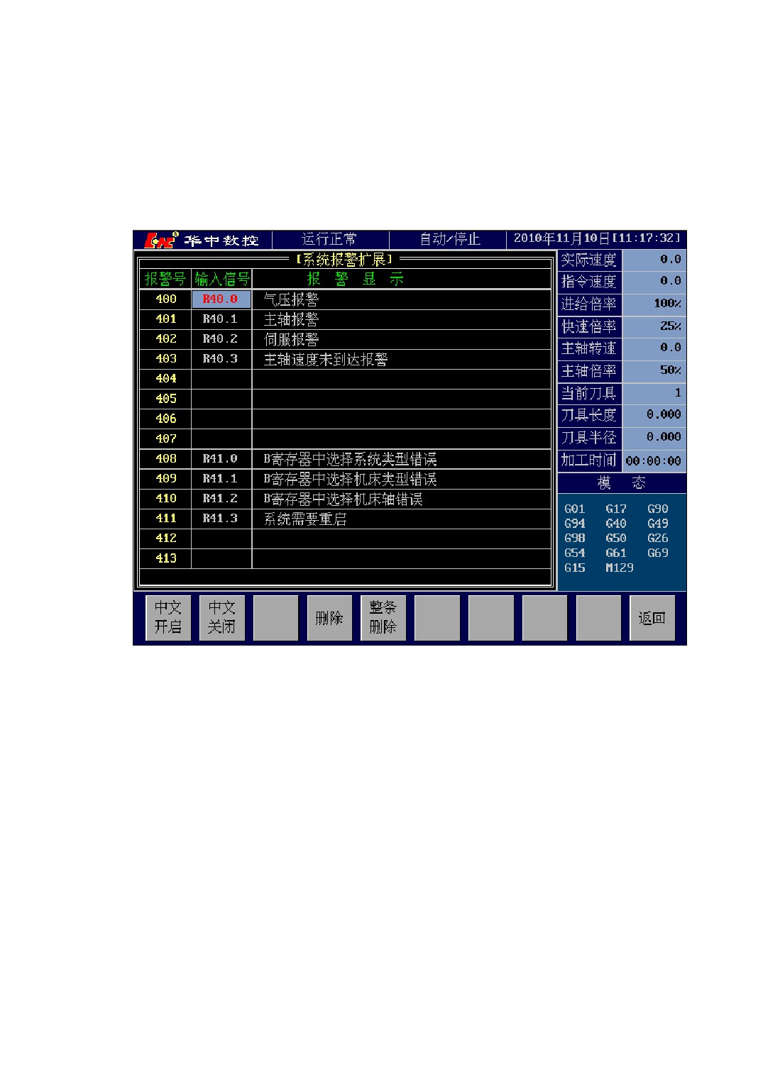
Method of entering into system alarm extension interface:[\] →[SSET] → [ALME]
System alarm extension interface is shown as Figure 6-7.
Figure 6-8
Alarm Extension Interface
The alarm item shows by three columns, the first column is alarm number, the
second column is used to set alarm input, the third is alarm display(namely displays the
clew words when system pops alarm). When you use alarm extension, you need to set
the input signal and alarm words.
The setting sequence of alarm extension definition is as follows:
1) Press [↑]、[↓]、[←]、[→] or [PageUp]、[PageDown] key to select the alarm item
which is needed to define.
2) After select the item, press [Enter] key or direct input a set value, then a input box
will pop up above the selected item;
3) Input the alarm’s relevant information into the pop-up input box;
4) After affirm the input correctness, Press [Enter] key again to confirm the input.
81
6.8 Authority Management
6.8.1 Summarize
The system authority is used for dividing and limiting the system function. You can
only use the system function which is equal to the authority of you have. The high
authority user can use the low authority function, but the low authority user can not use
the high authority function.
The system authority levels have three grades: system manufacturer authority,
machine manufacturer authority and end user authority. The authority level from high to
low is: system level authority > machine level authority > end user level authority.
System level and machine level authority can be opened only by inputing the
password, user level authority can be opened by the password and exterior input, namely:
when G22.0 is 1, direct open the user authority(needn’t input password); if G22.0 is 0 ,
you need to input the password to open.
6.8.2 Authority Management
1、Authority Password Modification:
Modification operation of system password: [\] →[PSWD] → [SPWD] → [SSPW]
Modification operation of machine password:[\]→[PSWD] → [SPWD]→ [SMPW]
Modification operation of user password: [\] →[PSWD] → [SPWD]→ [SUPW]
When modify the password, you need to input the old password and input twice new
password. Only when the input old password is correct and the new passwords twice
input are consistent, the password modification is successful.
2、Authority Password Input:
Input operation of system password: [\] →[PSWD] → [IPWD] → [ISPW]
Input operation of machine password: [\] →[PSWD] → [IPWD] → [IMPW]
Input operation of user password: [\] →[PSWD] → [IPWD] → [IUPW]
82
6.9 Macro Variable’s View and modification
The value of macro variables can be modified by code in macro program, as well as
be looked at and modified in the window.
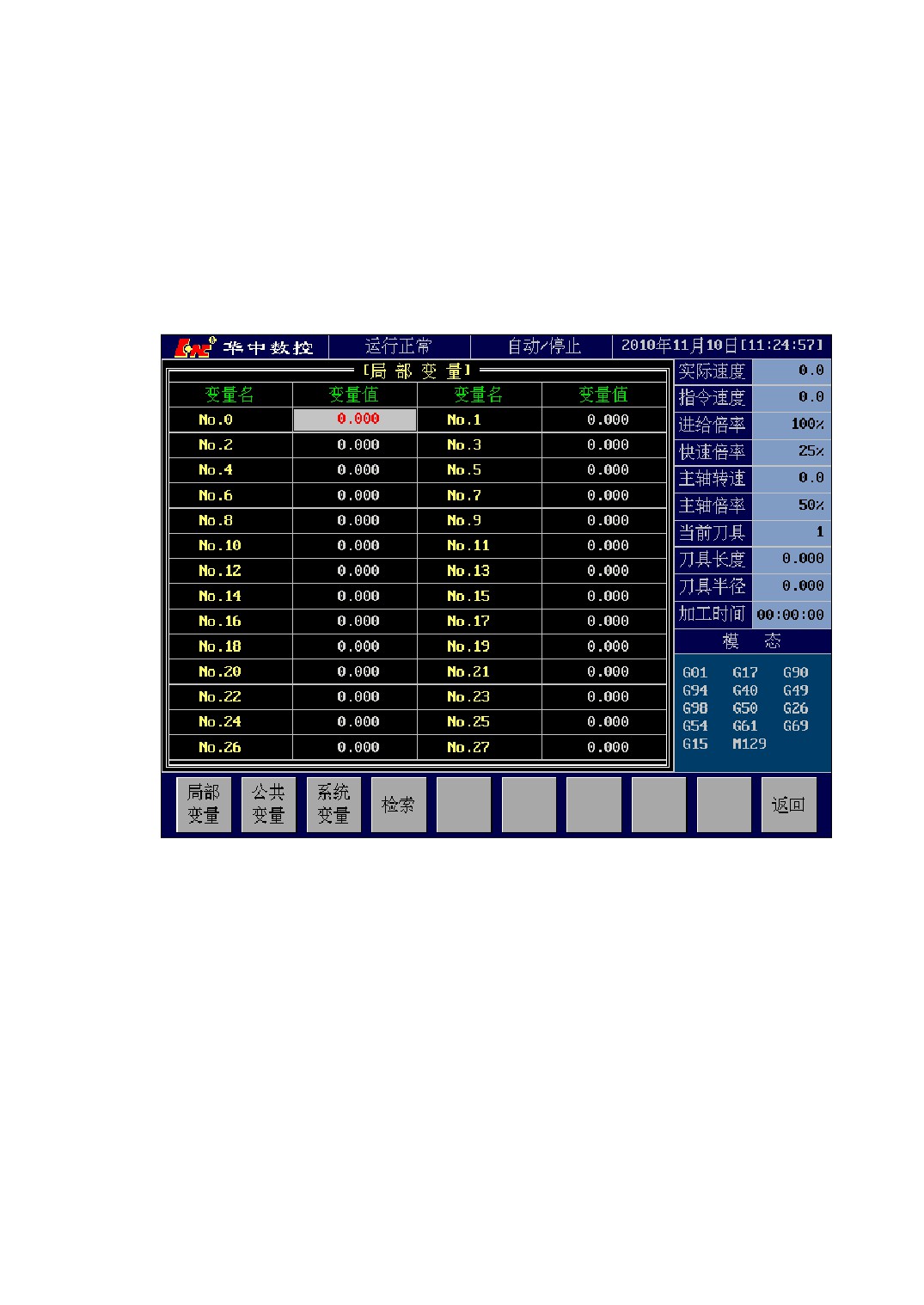
Method of entering into macro variables modification window: [\] → [VARI]
The macro variables window is shown as Figure 6-9.
Figure 6-9
Variables View and Modification Window
The macro variables are divided into local variables, public variables and system
variables, which can be switched by [LVAR], [PVAR], [SVAR] menus, the title bar will
show the variables type of the current display window.
You can lookup the specified variable name in current window by pressing [VSCH]
menu, but this can only search through variables type display in current window.
Namely, when the current window shows public variables, you can’t search the local
variables and system variables, the others are the same.
83