HNC-08M CNC SYSTEM CNC Milling System. Operation Manual (V1.22 2011/01) - page 1
HNC-08M CNC SYSTEM
CNC Milling System
Operation Manual
V1.22
2011/01
WuHan HuaZhong Numerical Control Co., Ltd
Table of Contents
1
SUMMARIZE
1
1.1
CNC SOFTWARE SYSTEM INTRODUCTION
1
1.1.1 CNC System Interface
1
1.1.2 CNC System Operation Mode
3
2
MANUAL OPERATION
4
2.1
MANUAL REFERENCE POINT RETURN
4
2.1.1 Process of Reference Point Return and Speed Setting
4
2.1.2 Direction Setting of Reference Point Return
6
2.1.3 Operation Sequence of Reference Point Return
6
2.1.4 Termination of the Reference Point Approach
6
2.2
MANUAL FEED OPERATION
7
2.2.1 Manual Step Feed
8
2.2.2 Manual Jog Feed
8
2.2.3 Manual Rapid Traverse
9
2.3
HANDWHEEL OPERATION
10
2.3.1 Parameter Setting About Handwheel Control
10
2.3.2 Operation Sequence of Handwheel Control
11
2.4
TOOL’S FIXED COORDINATE SYSTEM HANDWHEEL /JOG / INCREMENTAL FEED
11
3
AUTOMATIC OPERATION
13
3.1
LOADING A MACHINING PROGRAM
14
3.1.1 Program Preview
15
3.1.2 Loading a System Program
15
3.1.3 Loading a External Program
16
3.1.4 Loading a Network Program
18
3.1.5 Loading an Extended Program
19
3.1.6 The Syntax Checking Setting
20
3.2
START/PAUSE/STOP PROGRAM OPERATION
21
3.3
VERIFYING A PROGRAM
22
3.4
PROGRAM BREAKPOINT
23
3.4.1 Saving a Breakpoint
24
3.4.2 Resuming a Breakpoint
24
3.5
DEBUGGING A PROGRAM
25
3.6
HANDWHEEL INTERRUPTION
28
3.7
DNC
29
3.7.1 Transferring a File
29
3.7.2 On-Line Operation
30
3.7.3 DNC Setting
30
3.8
MDI OPERATION
31
3.8.1 MDI code input format
31
3.8.2 Sequence of MDI Operation
32
3.8.3 Suspending/Recovering/Terminating a Command
33
4
MANAGING A PROGRAM
35
4.1
CLASSIFICATION OF PROGRAM FILE
35
4.2
EDITING A PROGRAM FILE
35
4.2.1 Opening a Program File
35
4.2.2 Saving a File
37
4.2.3 Saving a File As
38
4.2.4 Finding/ Finding on
39
4.2.5 Replacing
40
4.2.6 Block Operation
41
4.3
MANAGING A PROGRAM FILE
43
4.3.1 The Window Of Program Management
44
4.3.2 Delete a Program File
46
4.3.3 Copy a Program File
47
4.3.4 Backup a Program File
48
4.3.5 Rename a Program File
49
4.3.6 Sort a Program File
50
5
GRAPHICS DISPLAY
52
5.1
SUMMARIZE
52
5.2
ENTER THE GRAPHICS SIMULATION INTERFACE
52
5.3
GRAPHICS OPERATION
53
5.4
GRAPHICS PARAMETER
54
5.4.1 Graphics Zoom Coefficient
54
5.4.2 Workpiece Size Range
54
5.5
SPEED CURVE DISPLAY
55
6
DATA INPUT
56
6.1
TOOL MAGAZINE CONFIGURATION
56
6.2
TOOL COMPENSATION
58
1
6.2.1 Summarize
58
6.2.2 Enter the Tool Compensation Table Interface
58
6.2.3 Method of Tool Compensation Parameter Setting
59
6.3
COORDINATE SYSTEM SETTING
61
6.3.1 Coordinate System Summary
61
6.3.2 Workpiece Coordinate System Setting
66
6.4
SYSTEM PARAMETERS SETTING
69
6.4.1 Parameter Classification Explanation
69
6.4.2 Paramter Type
70
6.4.3 Paramter Setting
70
6.4.4 Parameter Searching
72
6.4.5 Parameter’s Backup and Recovery
73
6.4.6 Parameters Export and Import
74
6.5
LOGIC AXIS CONFIGURATION
75
6.6
M-CODE’S EXTENSION DEFINITION
78
6.6.1 M-Code Summarize
78
6.6.2 M-Code’s Definition and Extension
79
6.7
SYSTEM ALARM DEFINITION AND EXTENSION
80
6.7.1 System Alarm Summarize
80
6.7.2 System Alarm’s Extension
81
6.8
AUTHORITY MANAGEMENT
82
6.8.1 Summarize
82
6.8.2 Authority Management
82
6.9
MACRO VARIABLE’S VIEW AND MODIFICATION
83
6.10
STATISTIC INFORMATION
84
7
PLC
85
7.1
PLC ONLINE PROGRAMMING AND DIAGNOSIS
85
7.1.1 Ladder Diagram Programming Interface
85
7.1.2 Ladder Diagram program Structural Unit
86
7.1.3 Programming Menu Illustration
87
7.1.4 Ladder Diagram Programming Demonstration
96
7.1.5 PLC Online Diagnosis
97
7.2
I/O DIAGNOSIS
97
7.2.1 I/O Diagnosis Summarize
97
7.2.2 I/O Diagnosis Interface
97
7.3
PLC DATA TABLE SETTING
98
7.3.1 Summarize
98
2
7.3.2 Data Table Operation Interface
100
7.3.3 Method of Data Table Setting
101
7.4
PLC ELEMENT DEFINITION
102
7.4.1 PLC Element Definition Summarize
102
7.4.2 PLC Element Definition Interface
102
7.5
B REGISTER
104
7.5.1 B Register Summarize
104
7.5.2 B Register Operation Interface
104
7.6
PLC MESSAGE
106
7.6.1 PLC Message Summarize
106
7.6.2 PLC Message Operation Interface
106
8
ROTATIONAL AXIS CIRCULATORY FUNCTION
108
9
SPINDLE GEAR CONTROL
110
9.1
METHOD OF SPINDLE GEAR CONTROL
110
9.2
SPINDLE GEAR CONTROL DEMONSTRATION
112
10 MEASUREMENT
114
10.1
TOOL MEASUREMENT
114
10.1.1
Tool Measuring Principle and Process
114
10.1.2
Tool Measure Operation Sequence
115
11 COMPENSATION SETTING
121
11.1
REVERSE BACKLASH COMPENSATION
121
11.2
PITCH ERROR COMPENSATION
121
11.3
DEFLECTION COMPENSATION
128
11.4
CIRCULAR ARC ACROSS QUADRANT COMPENSATION
129
12 SYSTEM ERROR AND SOLUTION
131
12.1
SYSTEM ALARM INDICATION
131
12.2
ALARM INFORMATION QUERY WINDOW
131
12.3
EMERGENCY STOP
132
12.4
STROKE TRAVEL SWITCH
132
12.5
SYSTEM SOFTWARE LIMITS ALARM
133
12.6
SYSTEM ALARM RECORD QUERY WINDOW
134
13 APPENDIX
136
13.1
APPENDIX ONE, SYSTEM PARAMETER DEFINITION
136
3
13.2
APPENDIX TWO, SYSTEM ALARM DEFINITION&SOLUTION
163
13.3
APPENDIX THREE, MACHINE TOOL STRUCTURE CODE
182
13.3.1
Tool Swing Head Structure
182
13.3.2
Workbench Structure
186
13.4
APPENDIX FOUR, MENU TREE STRUCTURE
189
14 OPERATION CORRECTING RECORDS
198
4
1 Summarize
1.1 CNC Software System Introduction
1.1.1 CNC System Interface
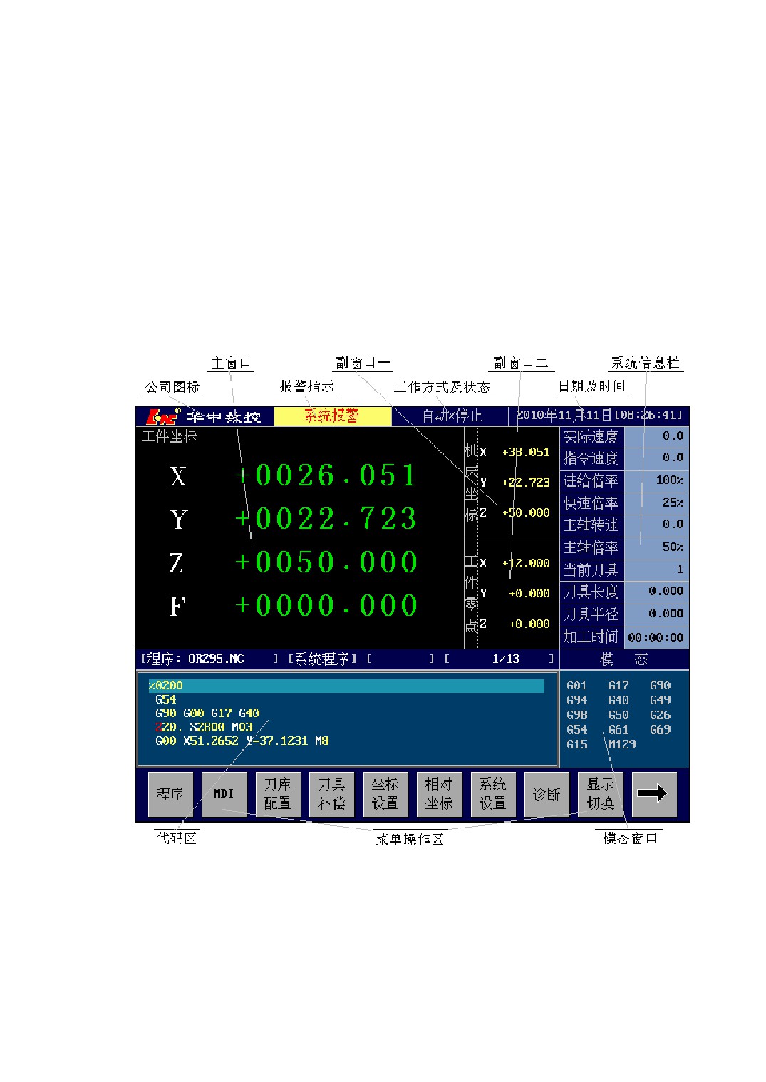
Figure 1-1 CNC System Interface
1、Alarm Show
This area displays alarm status of the system .Alarm status are divided into the
following:
1
1) System Reset: After press Overtravel released key when release Emergency Stop
Switch or over travel, system needs certain time to reset. During this period,
system can not be operated, and the Alarm Display area shows “Reset”.
2) Over Travel: When the workbench stroke travel switch, system turns up overtravel
alarm and the Alarm Display area shows “Reset”.
3) Emergency Stop: When press E-Stop button down, system turns up emergency stop
alarm and the Alarm Display area shows “E-Stop”.
4) System Alarm: When turns up other alarms except the mentioned above, the Alarm
Display area shows “System-Alarm”.
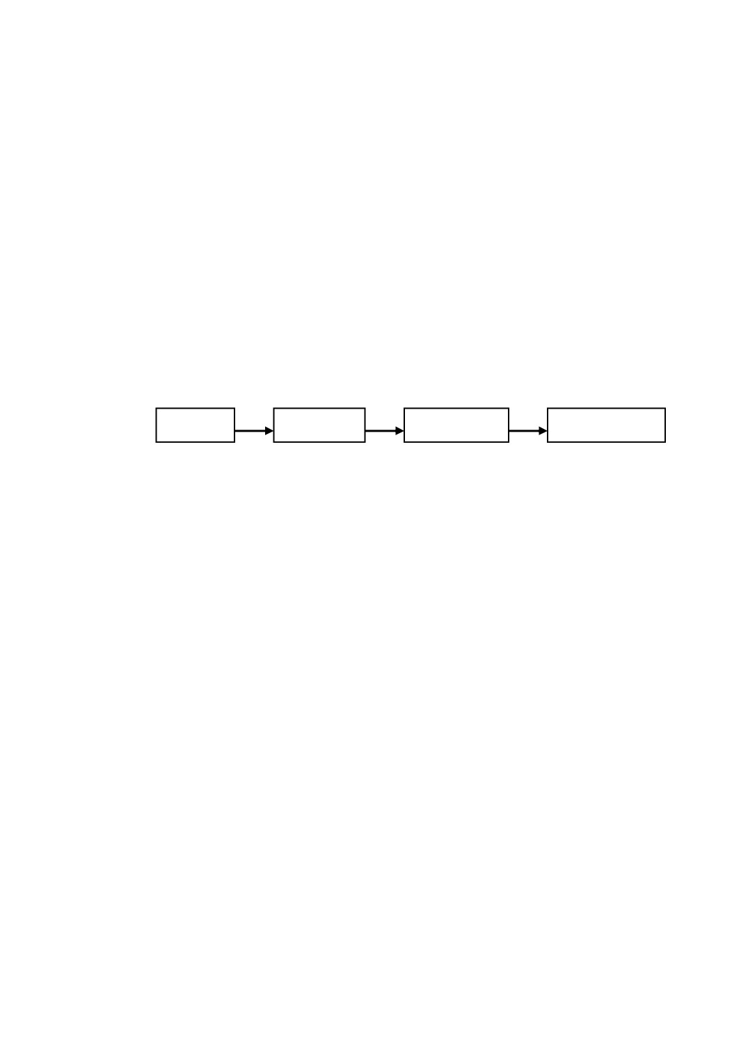
When the alarms above occur at the same time, the priority displayed in the Alarm
Display area is the following (the left has high priority, that means it will be shown in
front of others when alarm appear):
Reset
Overtravel
E-Stop
System-Alarm
2、Working and Running Status
There are three kinds of operation modes: Automatic,Manual and Handwheel.
Every mode has stop, run and pause status by machine tool’s running status. The
Working and Running Status area shows in real-time what is the current operation mode
and running state. For example, “Manu/Stop”means the current operation mode is
“Manual”, and machine tool’s running status is “Stop”(halted state).
3、Main Window Show
The Main Window displays tool’s position in workpiece coordinate system or machine
coordinate system, that is workpiece coordinate or machine coordinate. The coordinate
system which displays can be changed by setting parameter P0017.
4、First Side Window Show
First Side Window displays tool’s position in machine coordinate system or
workpiece coordinate system, that is machine coordinate or workpiece coordinate.The
coordinate system which displays can be changed by setting parameter P0017.
5、Second Side Window Show
Second Side Window can display workpiece coordinate zero, synchronization error
2
or tracking error by setting parameter P0016.
6、System Information Area
The System Information Area displays machining information of CNC, include:
actual speed, instruction speed, feedrate override, rapid traverse speed override, spindle
speed, spindle override, current tool, tool length, tool radius and machining time ect.
7、Code Window
In automatic mode, the window displays machining code and index of current
machining line. when the mode is MDI, you can input MDI instructions in the window.
1.1.2 CNC System Operation Mode
All of this CNC system function is followed by operation mode, that is to say all of
functions belong to part of functions in a certain operation mode, you can only operate
under the appropriate operation mode.
CNC is divided into the following three operation mode:
1) Automatic Mode: In automatic mode, you can automatically execute part
programs, transfer file and machining while transfering ect. Automatic mode
can be switched by pressing <AUTO> key.
2) Manual Mode:In manual mode, you can operate reference point return, Jog and
step control ect. Manual mode can be switched by pressing < MANU > key.
3) Handwheel Mode:In handwheel mode, you can control machine tool by hand.
Handwheel mode can be switched by pressing < Increment > key.
During CNC running, there are two methods to judge the current operation mode:
1) among operation mode switch keys, which the indicator lights of keys is on indicates
in which mode the machine is working;
2) CNC software interface show the current operation mode in Working and Running
Status bar, such as“Manual/Stop”.
When switched operation mode, system menu automaticly return main menu mode.
3
2 Manual Operation
Manual operations include two kinds of operation modes:reference point return mode
and manual feed mode. The first mode is used to set up the machine coordinate system
with all axes returned to the origin position; the second mode is used to move all
coordinate axis manually. The two modes can be switched to each other by pressing
<REF> key. The first mode is active when the indicator light of < REF > key is on. The
second mode is active when the light is off.
2.1 Manual Reference Point Return
2.1.1 Process of Reference Point Return and Speed
Setting
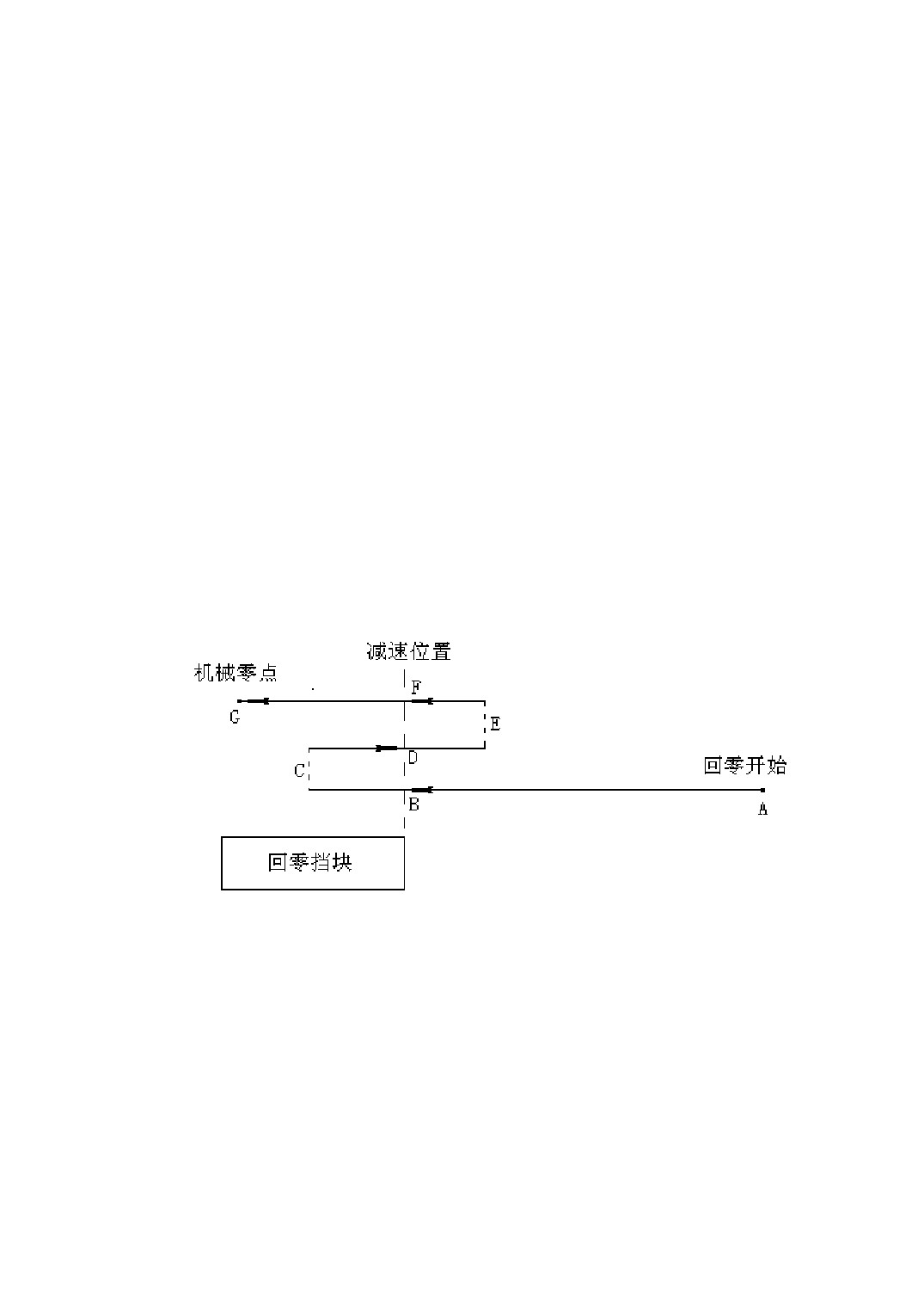
Figure 2-1 Process of Reference Point Return map
The process of returning reference point includes three steps(as shown above):
1) Start from point A, move to point B. Then it will slow down from point B when
detecting the signal from the pressed reference point block to point C. At the first
step, which belong to high speed position period, you can set higher moving speed.
The speed of returning reference point is determined by parameters as follows:
P3021: X-axis high speed returning home speed(mm/min)
P3022: Y-axis high speed returning home speed(mm/min)
P3023: Z-axis high speed returning home speed(mm/min)
4
P3024: Fourth-axis high speed returning home speed(degree/min)
P3025: Fifth-axis high speed returning home speed(degree/min)
P3026: Sixth-axis high speed returning home speed(degree/min)
P3027: Seventh-axis high speed returning home speed(degree/min)
P3028: Eighth-axis high speed returning home speed(degree/min)
2)
From point C move to point D backward. It will slow down from point D when
detecting the signal from the up reference point block to point E. Then reverse again,
move to point F when detect the signal again from the pressed reference point block.
The second step belongs to low speed return period, which speed of returning
reference point is determined by parameters as follows:
P3031: X-axis low speed returning home speed(mm/min)
P3032: Y-axis low speed returning home speed(mm/min)
P3033: Z-axis low speed returning home speed(mm/min)
P3034: Fourth-axis low speed returning home speed(degree/min)
P3035: Fifth-axis low speed returning home speed(degree/min)
P3036: Sixth-axis low speed returning home speed(degree/min)
P3037: Seventh-axis low speed returning home speed(degree/min)
P3038: Eighth-axis low speed returning home speed(degree/min)
3)
After move to point F when detect the signal from the pressed reference point block,
it enters into the third step: searching for zero. Due to the limited of motor’s zero
pulse width, the speed of searching for zero can’t be set too high, or it’s possible
failure to return reference point for missing zero pulse. On the other hand, it could
affect precision of reference point return if the speed is too large. The speed of
returning reference point is determined by parameters as follows:
P3041: X-axis searching for zero speed at low speed(mm/min)
P3042: Y-axis searching for zero speed at low speed(mm/min)
P3043: Z-axis searching for zero speed at low speed(mm/min)
P3044: Fourth-axis searching for zero speed at low speed(degree/min)
P3045: Fifth-axis searching for zero speed at low speed(degree/min)
P3046: Sixth-axis searching for zero speed at low speed(degree/min)
P3047: Seventh-axis searching for zero speed at low speed(degree/min)
P3048: Eighth-axis searching for zero speed at low speed(degree/min)
The actual speed of reference point return can be adjusted by feedrate override at
the first two steps(high speed position period and low speed return period), that is:
5
the actual returning speed = the parameter value * feedrate override.
At the third step, that is searching for zero at low speed, the actual speed of
reference point return is equal to the parameter value for ensuring precision and
repetition, no feedrate override.
2.1.2 Direction Setting of Reference Point Return
Each axis’s direction of returning reference point is determined by parameters as
follows:
P3011: X-axis returning direction [0- positive direction; 1- negative direction]
P3012: Y-axis returning direction [0- positive direction; 1- negative direction]
P3013: Z-axis returning direction [0- positive direction; 1- negative direction]
P3014: Fourth-axis returning direction [0- positive direction; 1- negative direction]
P3015: Fifth-axis returning direction [0- positive direction; 1- negative direction]
P3016: Sixth-axis returning direction [0- positive direction; 1- negative direction]
P3017: Seventh-axis returning direction [0- positive direction; 1- negative direction]
P3018: Eighth-axis returning direction [0- positive direction; 1- negative direction]
2.1.3 Operation Sequence of Reference Point Return
1) Press <MANU> key on the Machine Control Panel (MCP). Be sure the key’s
indicator light is on and “Manual/Stop” is displayed in the status bar;
2) Press < REF > key in manual mode. Be sure the key’s indicator light is on;
3) Press one of the feed axis keys: X, Y, Z, 4, 5, 6 ,7 or 8 on the MCP that the
corresponding axis needs reference point return. For example, the X-axis will
return to the reference point when press the <X> key. Furthermore, the specified
axes will return to the reference point simultaneously when select more than one
axis in turn;
4) The reference point return for the specified axis is finished when the specific
machine coordinate value retains 0 and doesn’t change.
2.1.4 Termination of the Reference Point Approach
Two methods of terminating the operation during the returning (including three
6
periods: high speed return, low speed return, searching for zero):
a) Press the < REF > key to make sure the key’s indicator light is off, Then the
returning is terminated and the system is switched to the manual feed mode,
which can move each axis using Jog manner;
b) Press the <FDHD> key, then the returning is terminated. To switch to the
manual feed mode that you need to press < REF > key again and make sure
the indicator light of < REF > key is off.
Note that each method above will terminate the returning for all axes.
Note:
1、 Adjust the position of the workbench and cutter before the operation, in case to
avoid movement interference during the returning;
2、 The return speed can be adjusted by feedrate only in the high speed return period or
low speed return period. It is invalidation for the speed in the period of searching
for zero;
3、 It is not appropriate to setting the speed of searching for zero too large, or the
position error will be very large.
2.2 Manual Feed Operation
Two kinds of the manual feed operation:
7
1、 Manual Step Feed: When an axis key is pressed, the workbench will move one step
distance and then stop automatically.
2、 Manual Jog Feed: Move the tool along a motion axis in the specific direction, while
an axis key is being pressed. The motion continues as long as the axis key is pressed.
The tool will decelerate to stop when the axis key is released.
2.2.1 Manual Step Feed
It is the manual step feed mode when the LED indicator light of one of the step length
keys like <×1>、<×10>、<×100>、<×1000> is on. The step length is followed by the
keys:
<×1> ----- 0.001mm
<×10> ----- 0.01mm
<×100> ----- 0.1mm
<×1000> ----- 1mm
Sequence of manual step feed:
① Switch to the manual mode;
② Press one of the step length keys according to step length. Be sure the LED indicator
light of the selected key is on;
③ Select a feed axis. Be sure the LED indicator light of the selected key is on;
④ When press <-> or <+> key according to the need of the moving direction, the
selected asix begins to move, and decelerates to stop after moves one step length
distance.
2.2.2 Manual Jog Feed
It is the manual point feed mode when all of the indicator lights of the step length
keys like <×1>、<×10>、<×100>、<×1000> is off.
Sequence of manual jog feed:
8
① Switch to the manual mode;
② Be sure all of the indicator lights of the step length keys is off;
③ Select a feed axis. Be sure the LED indicator light of the selected key is on;
④ When press <-> or <+> key according to the need of the moving direction, the
selected asix begins to move. Release the key after it gets to the target position, and
the asix will decelerate to stop automatically.
Note:
Due to the process of deceleration stop when the axis stops(release <JOG> key) in
the manual jog feed mode, it is necessary to remain enough space for extra motion to
avoid some accidents.
2.2.3 Manual Rapid Traverse
There are high gear and normal gear for the theoretical speed of an axis in the manual
feed mode. They can be switched to each other using <SPUP> key.
High Gear: The manual feed is on high gear when the LED indicator light of the
<SPUP> key is on. The instruction speed is set by the parameters P2011~P2018. The
actual moving speed = the parameter value * feedrate override.
Normal Gear: The manual feed is on normal gear when the LED indicator light of
the < SPUP > key is off. The instruction speed is set by the parameters P2021~P2028.
The actual moving speed = the parameter value * feedrate override.
Note:
1、 Both high gear and normal gear are effective in the manual step feed mode or the
manual jog feed mode;
2、 The acceleration of the manual operation is set by the parameters P2080~P2087.
9
2.3 Handwheel Operation
2.3.1 Parameter Setting About Handwheel Control
1) Handwheel Pulse Equivalent
Handwheel pulse equivalent means the moving distances (or rotary angles) of
the axis by rotating one pulse(one frame) when handwheel is at the ×1 times. The
moving distances when you rotate handwheel is:
the moving distances(or angles) = handwheel pulse number * handwheel
Magnification * handwheel pulse equivalent
handwheel pulse equivalent is set by the following parameters:
P0237: Handwheel equivalent for linear axis(mm/frame)
P0238: Handwheel equivalent for rotational axis(degree /frame)
2) The Maximum Speed Limit Under Handwheel Operation
When control the motion of workbench by handwheel, the maximum speed of the
workbench’s motion will be less than the value by setting the following parameter:
P0234: The maximum speed of Handwheel for linear axis(mm/frame)
P0235: The maximum speed of Handwheel for rotational axis(degree /min)
3) The Maximum Acceleration Limit Under Handwheel Operation
When control the motion of workbench by handwheel, the maximum acceleration of
the workbench’s motion will be less than the value by setting the following parameter:
P0231: The maximum acceleration of Handwheel for linear axis
P0232: The maximum acceleration of Handwheel for rotational axis
4) Direction Setting of Handwheel
When the direction of the workbench’s motion by handwheel control is incorrect,
the direction of the workbench’s motion can be changed by setting the following
parameter:
P0230=1: reverse the direction of handwheel control
P0230=0: not reverse the direction of handwheel control
10
2.3.2 Operation Sequence of Handwheel Control
In the handwheel mode, you can using the micro-feed by turning the handwheel
pulser as follow:
1) Press< Increment >key to switch to the handwheel mode (Be sure the indicator
light of the < Increment >key is on, and the CNC system shows“Handwheel/Stop”
in Working and Running Status bar);
2) Turn the axis switch, and select the axis which you want to operate (when the switch
points to OFF, the handwheel is closed and you can operate no axis);
3) Turn the magnification switch, and select an appropriate magnification;
4) Turn the handwheel, and move the selected axis.
2.4 Tool’s Fixed Coordinate System Handwheel /JOG
/ Incremental Feed
The tool’s fixed coordinate system means the local coordinate system which is set
up on the tool and parallel to machine coordinate system when the tool is at the
beginning position(the tool axis is parallel to the Z-axis in machine coordinate system).
During the tool rotating, coordinate system rotate along with the tool, fixed joint the
tool all the time.
Wherever the coordinate system rotate to along with the tool, it can be moved along
the axis of the tool’s fixed coordinate system by hand. The operation includes handwheel,
jog and incremental mode.
11
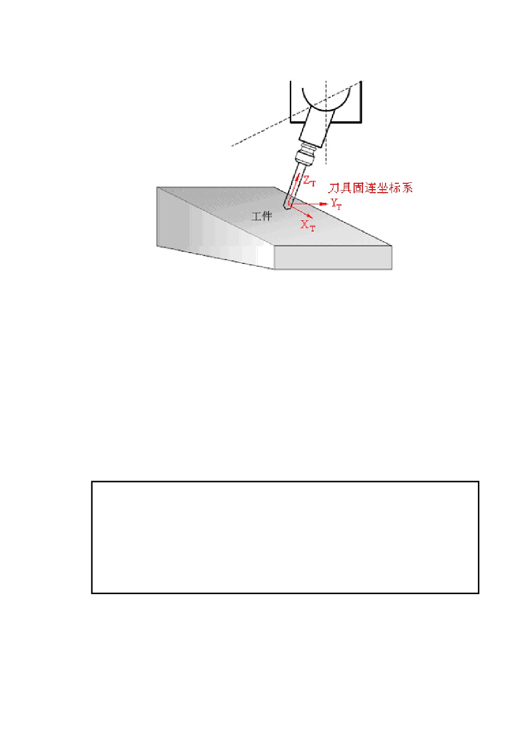
Figure 2-2 Tool’s Fixed Coordinate System
The method of opening up the feed function of tool’s fixed coordinate system:
<Manual/Increment> →[\] → [Tool Axis Feed] → [Open]
The method of closing up the feed function of tool’s fixed coordinate system:
< Manual/Increment> →[\] → [Tool Axis Feed] → [Close]
After opening up the feed function, when move the Z-axis by handwheel, jog or
increment mode, the tool will move along the Z-axis’s direction in the tool’s fixed
coordinate system(tool aixs’s direction ); Similarly, when move the X-axis,Y-axis by
handwheel, jog or increment mode, the tool will move along the direction of
X-axis,Y-axis in the tool’s fixed coordinate system.
Note:
1、 It’s necessary to set the machine’s structure type correctly by the parameter of
P400 and P401, or the feed function can not be implement accurately;
2、 Only the machine’s structure type which system support can be implemented the
feed function, or the correctness of machine tool’s motion cannot be guaranteed.
12
3 Automatic Operation
In Automatic machining mode, you can execute a part program or a MDI command.
Four types of programs can be executed in automatic mode: system program,
external program , network program and DNC on-line program.
System Program: It is stored in the system’s built-in disk;
External Program: It is stored in some removable storage devices with USB interface,
such as U disk, removable disk etc.;
Network Program: It shares the storage area which is a directory of computer by
network mapping.
DNC On-Line Program: Receive the part programs from the DNC server, and execute
while transmit.
A program should be loaded to memory before automatic machining. System program,
external program and network program can be loaded to memory by CNC system and
executed directly.
13
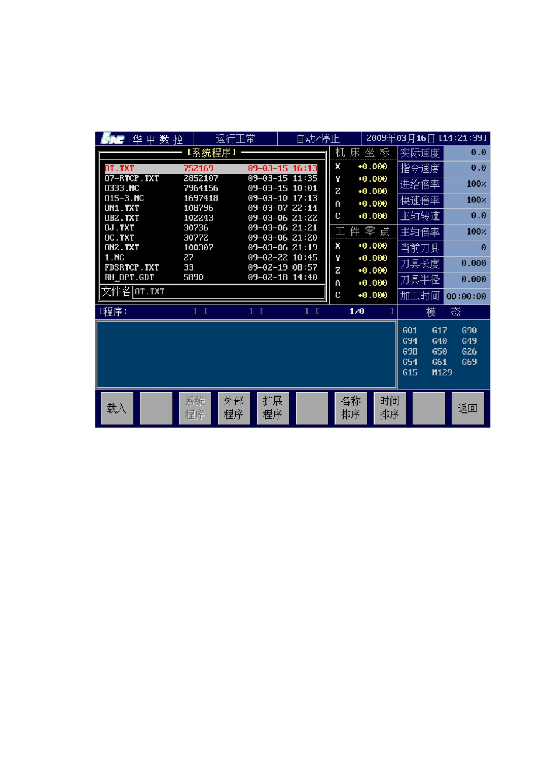
3.1 Loading a Machining Program
Figure 3-1 Program Selection Screen
Sequence of entering the program loading screen:
<AUTO> → [\] → [PROG] → [LDPG].
It is shown in the figure 3-1 above.
The system menu which is workable in program selection screen includes:
[LOAD]: Load the selected program to the memory.
[SPGM]: Show a list of program files from the system’s internal storage.
[UPGM]: Show a list of program files from the external storage.
[NPGM]: Show a list of program files from the NC port by network mapping.
[EPGM]: Show a list of extended program files.
[NSRT]: Sort a list of program files by name;
[TSRT]: Sort a list of program files by modification time;
[PRET]: Load nothing and return to previous menu.
14
3.1.1 Program Preview
In the program selection screen, after the cursor select a program, you can preview
the selected program in the program preview screen on the right, as figure 3-1shown.
3.1.2 Loading a System Program
Sequence of loading a system program is as follows:
1) Switch to the program selection screen;
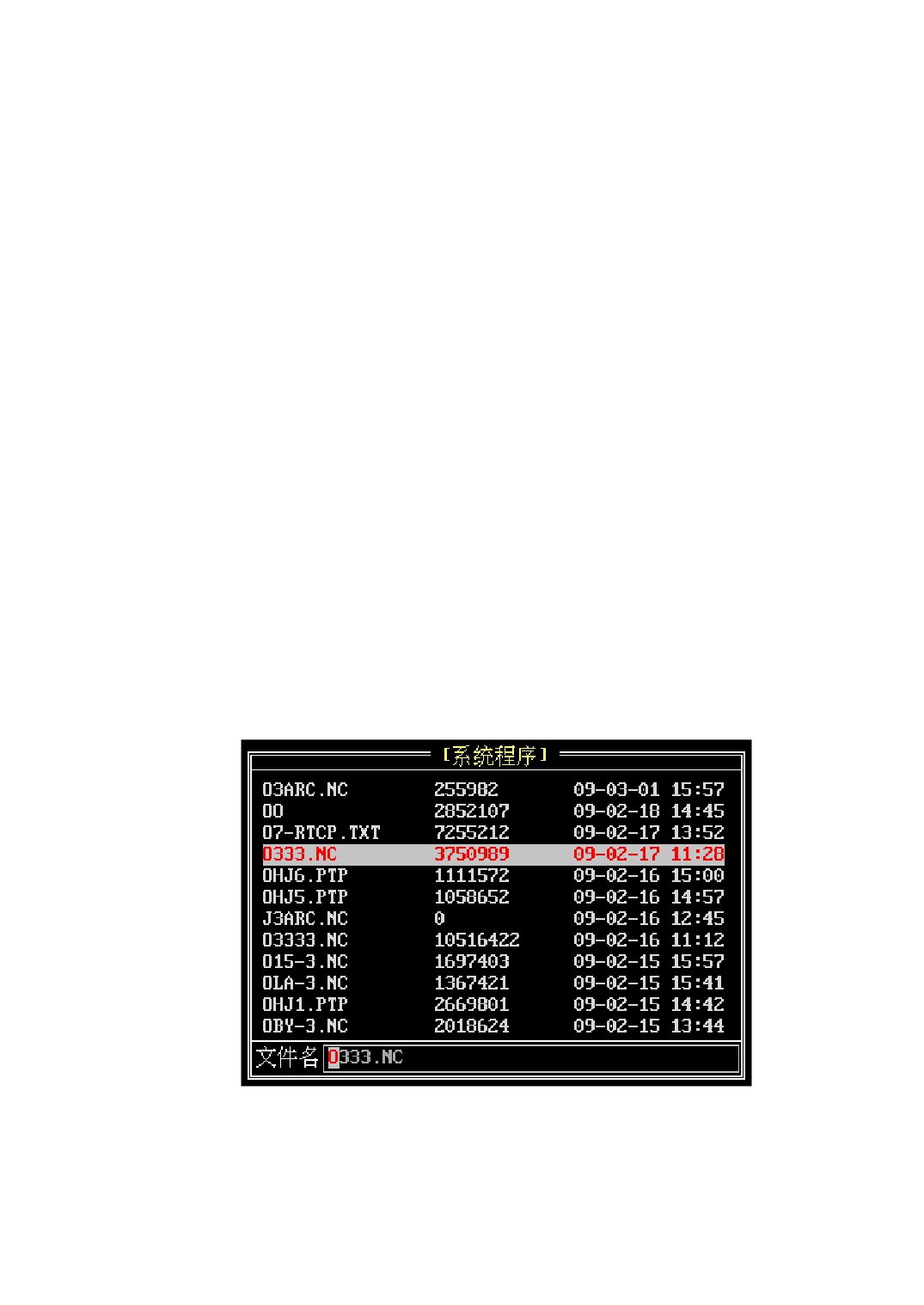
2) Show a list of system program files. The LCD screen shows a list of system program
conventionally when you enter into the program selection screen at the first time. If
it doesn’t show the list after some operations, you need press [SPGM] key to switch
to it. The list window title bar shows the storage of the current indicated program. It
shows “System Program” means that the displaying program is from the system’s
internal storage, as figure 3-2 shown;
3) Use the [↑]、[↓] or [PageUp]、[PageDown] keys to select a program which need
loading, or input the filename into the window of program filename directly.
4) Press the [LOAD] key to load the selected program to memory.
Figure 3-2 A list of system program files
If the parameter P0003 value is 1, CNC system will check the syntax of the loaded
15
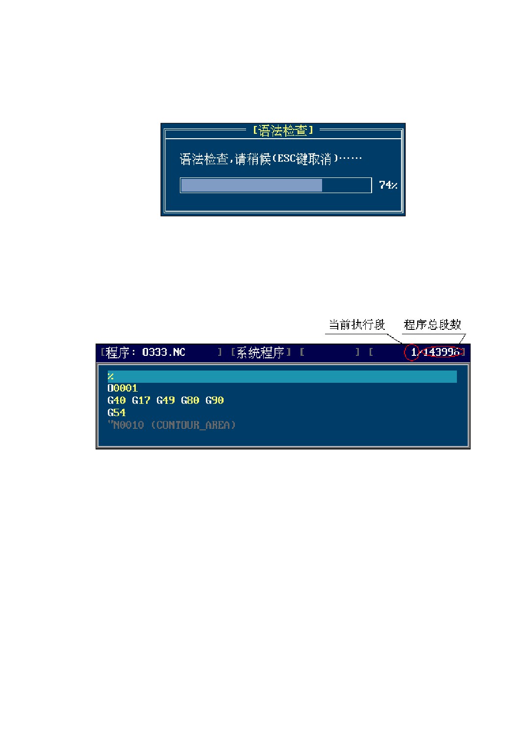
program after loading (as figure 3-3 shown). If you are sure that the program has no
syntax error, you can press the [ESC] key to cancel syntax checking.
Figure 3-1 Program Syntax Checking
the content of the loaded program is shown in the code window, as figure 3-4 shown.
Use the [↑]、[↓] or [PageUp]、[PageDown] keys to read the program before automatic
operation.
Figure 3-2 Code Display Window
3.1.3 Loading a External Program
Sequence of loading an external program is as follows:
1) Switch to the program selection screen;
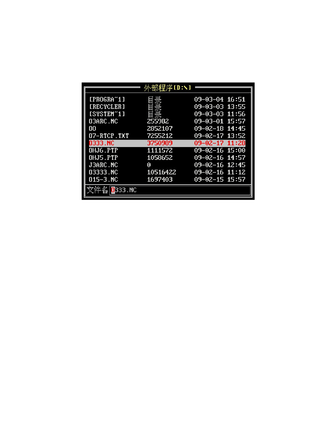
2) Show a list of external program files. The LCD screen shows a list of system
program conventionally when you enter into the program selection screen at the
first time. Press the [UPGM] key to switch the screen to it. The list window title
bar shows the storage of the current indicated program. It shows “External
Program” means that the displaying program is from the external storage device,
as figure 3-5 shown;
16
3) Use the [↑]、[↓] or [PageUp]、[PageDown] keys to select a program which need
loading, or input the filename into the window of program filename directly.
4) Press the [LOAD] key to load the selected external program to memory.
Figure 3-5 A list of external program files
If there are no external storage devices and you press the [UPGM] key, the title bar
will show a warning prompt, as figure 3-6 shown. Press any key in the panel can remove
this prompt .
17
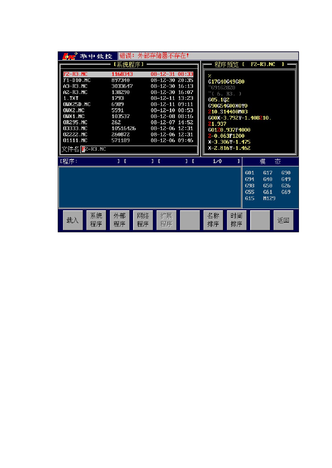
Figure 3-6 No External Storage Devices
3.1.4 Loading a Network Program
The operation of loading a network program is the same as loading an external
program. If the CNC syatem has been configured the network-mapping device, the
program in the network-mapping device can be shown after you select the network
program, as figure 3-7 shown.
18
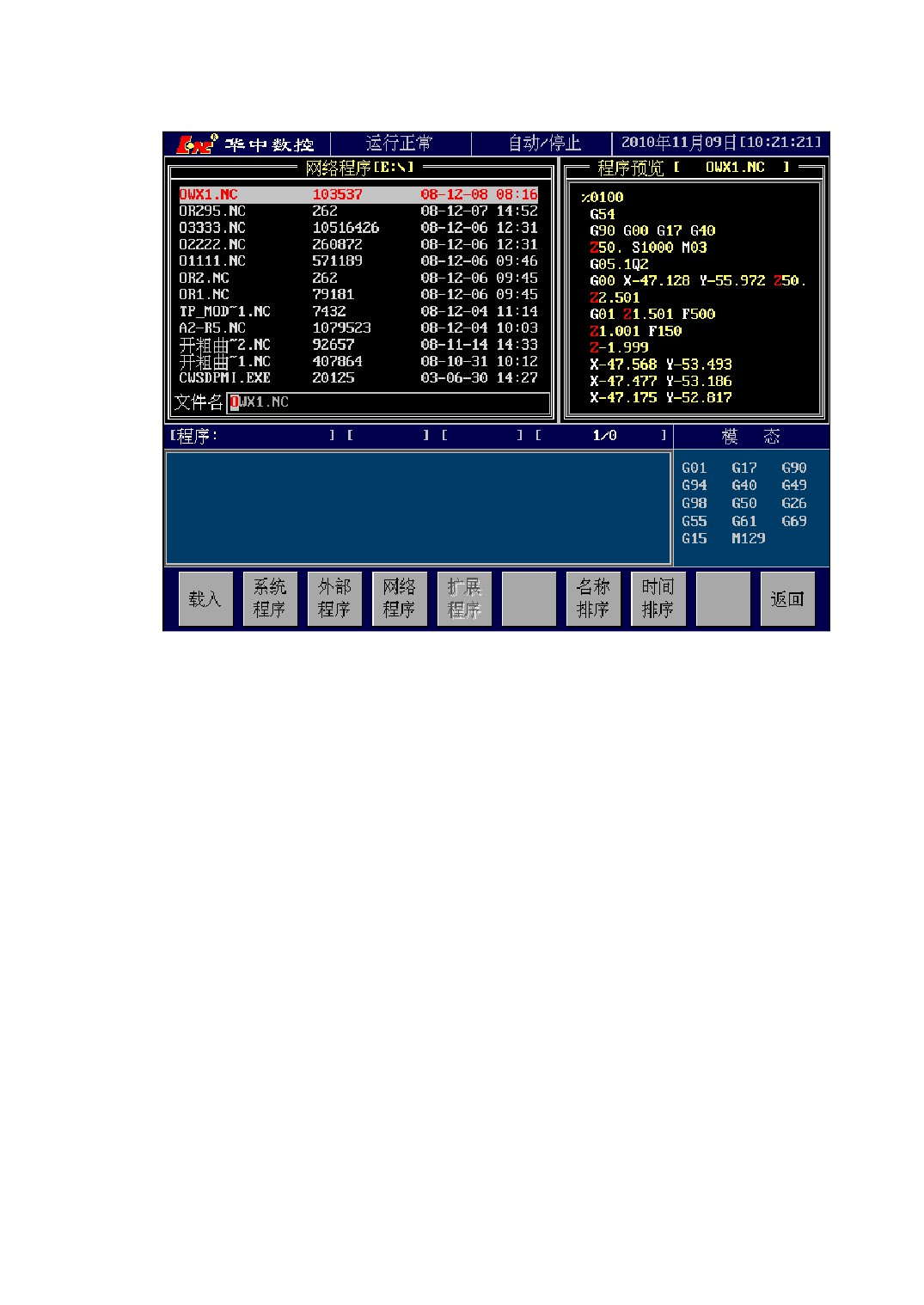
Figure 3-3 Network Program Loading Interface
3.1.5 Loading an Extended Program
In general, the extended program key is gray, which is not operating. The key can be
recovered operation by setting the parameter P0002, as figure 3-8 shown.
19
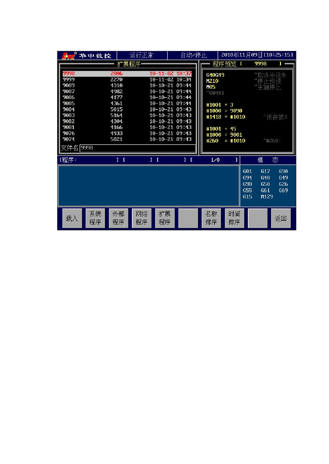
Figure 3-4 Extended Program Loading Interface
The extended program can be loaded into memory to read、edit、modify、save, but
it is not recommended to operate the extended program, so you’d better set 1 for the
parameter P0002 to hide and protect it.
3.1.6 The Syntax Checking Setting
Generally, CNC system will check the syntax of the loaded program after loading.
If there are some mistakes in syntax checking, the loaded program can’t be executed.
The function of syntax checking is set by the parameter P0003:
P0003=0: Don’t check the syntax when loading program
P0003=1: Check the syntax when loading program
You’d better use this function in practice to ensure the loaded program works
normally.
20
3.2 Start/Pause/Stop Program Operation
1、 Program Startup
Press the <CYCL> key to execute the program when it has been loaded into
memory. Then the LED indicator light of the < CYCL > key is on and “Auto/Run” is
shown in Working and Running Status bar. Press the [↑]、[↓] or [PageUp]、[PageDown]
keys to position the current cursor where the program begins to be executed before
starting.
Note:
Be careful of starting from a random segment to execute the program. Because the
beginning segment of the program hasn’t been executed, If the loaded program includes some
subroutine calls or macro programs and the codes after the selected segment doesn’t contain the
whole information of establishment process (such as establishing the stack for a subroutine call,
assigning variables etc.), there may be an exception occured during the program execution.
Furthermore, the MST codes before the beginning segment are not effective, so you should
ensure that the auxiliary functions are effective, such as spindle rotation, cooling on etc..
2、 Program Pause
Press <FDHD> key to stop the running program during execution. After that, The
LED indicator light of <FDHD> key is on and “AUTO/PAUS” is displayed in Working
and Running Status bar. The program is paused but doesn’t exit from the processing state,
then pressing <CYCL> key can resume the execution.
You can switch to the manual mode or the handwheel mode to move an axis in state
suspended. Note when you switch back to the automatic mode to resume the execution,
system will automatically return to the position of interruption, so be sure there is no
motion disturbance in the returning process.
3、 Program Stop
Two methods to terminate the current process of execution:
1)Method with pressing the [STOP] key
21
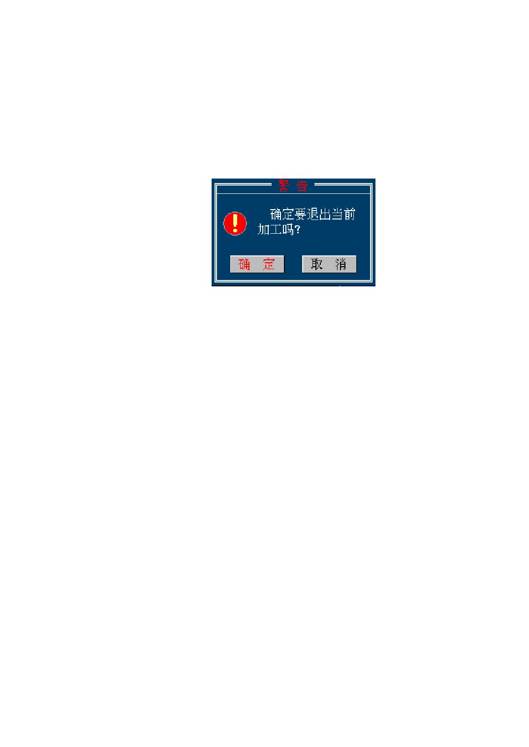
Firstly, press the <FDHD> key (or SBL stop)to make the execution pause, then
press the [PROG] key→[STOP] key in turn and then it will pop up a dialog, as figure
3-9 shown. At the time, pressing the [ENTER] key will terminate the execution or
pressing the [ESC] key will cancel the stop operation. CNC system’s state is the same
as that before running (the modal codes of the program have been stored), Then the
Working and Running Status bar will show “AUTO/STOP”.
Figure 3-9 A dialog of terminating a running program
2)Method with pressing the [RNGN] key
This method is similar to the prior method. Both of them can exit from the current
processing state. The difference is: In the first method, the current line remains the
machining line when exit, but in the second method, the current line automatically
returns to the first line of the program.
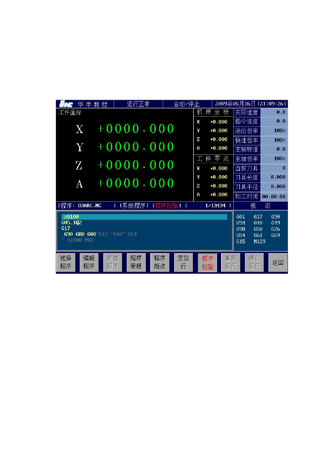
3.3 Verifying a Program
When write a new program, you can use the program verification function to test the
working path is right or not.
During the process of verifying a program, the M codes except M00,M01,M06,
M30,M98,M99,M128,M129 and all the S, T codes aren’t effective.
Sequence of verifying a program is as follows:
1) Switch to the mode of verifying a program. Press these keys as follows in turn:
<AUTO> →[\] → [PROG] → [TEST];
2) Press the <CYCL> key to start the program verification.
The mode of verifying a program will be closed in these situations as follows:
1) When verifying a program, Press<FDHD>, and then select <STOP> or <RNGN>,
22
the system will automatically close the program verification mode;
2) When verifying a program, Press<FDHD>key and then quit from the automatic
mode, the system will automatically close the program verification mode;
When the program verification mode is closed, it returns to the normal running mode.
Figure 3-10 Verifying a program
3.4 Program Breakpoint
During the process of machining, For some reason you may turn off the machine
halfway. The breakpoint means that the segment of the program executing and the
machine tool’s position and status messages when turn off. So the breakpoint saving and
recovering fuction is important when resume running from the program breakpoint.
23
//////////////////////