Rexroth: Screw Assemblies. Catalog (R999001185/2018-10) - page 12
166
Screw Assemblies | Ball Screw Assemblies BASA
Lubrication
Oil lubrication with a single-line piston distributor system
Oil lubricant
We recommend using Shell Tonna S 220
--
Special demulsifying oil CLP or CGLP as per DIN 51517-3 for machine bed tracks and
with the following properties:
tool guides
--
A blend of highly refined mineral oils and additives
-–
Can be used even when mixed with significant quantities of metalworking fluids
Initial lubrication of the Ball Screw
Assemblies (basic lubrication)
Fully assembled BASAs with a diameter less
When individual parts are supplied (nut on
When using single-line distributor systems,
than or equal to 12 mm are prelubricated at
mounting arbor) or in the case of special
care should be taken that all lines and the
the factory with Dynalub 520.
designs without basic lubrication at the
piston distributors (including the connection
factory, you must apply double the quantity of
to the BASA nut) are filled before performing
Fully assembled BASAs with a diameter
lubricant stated in table “Amount of lubricant
basic lubrication or relubrication.
greater than 12 mm are prelubricated at the
for oil lubrication” on page 167 via the nut’s
factory with Dynalub 510.
lube hole before commissioning.
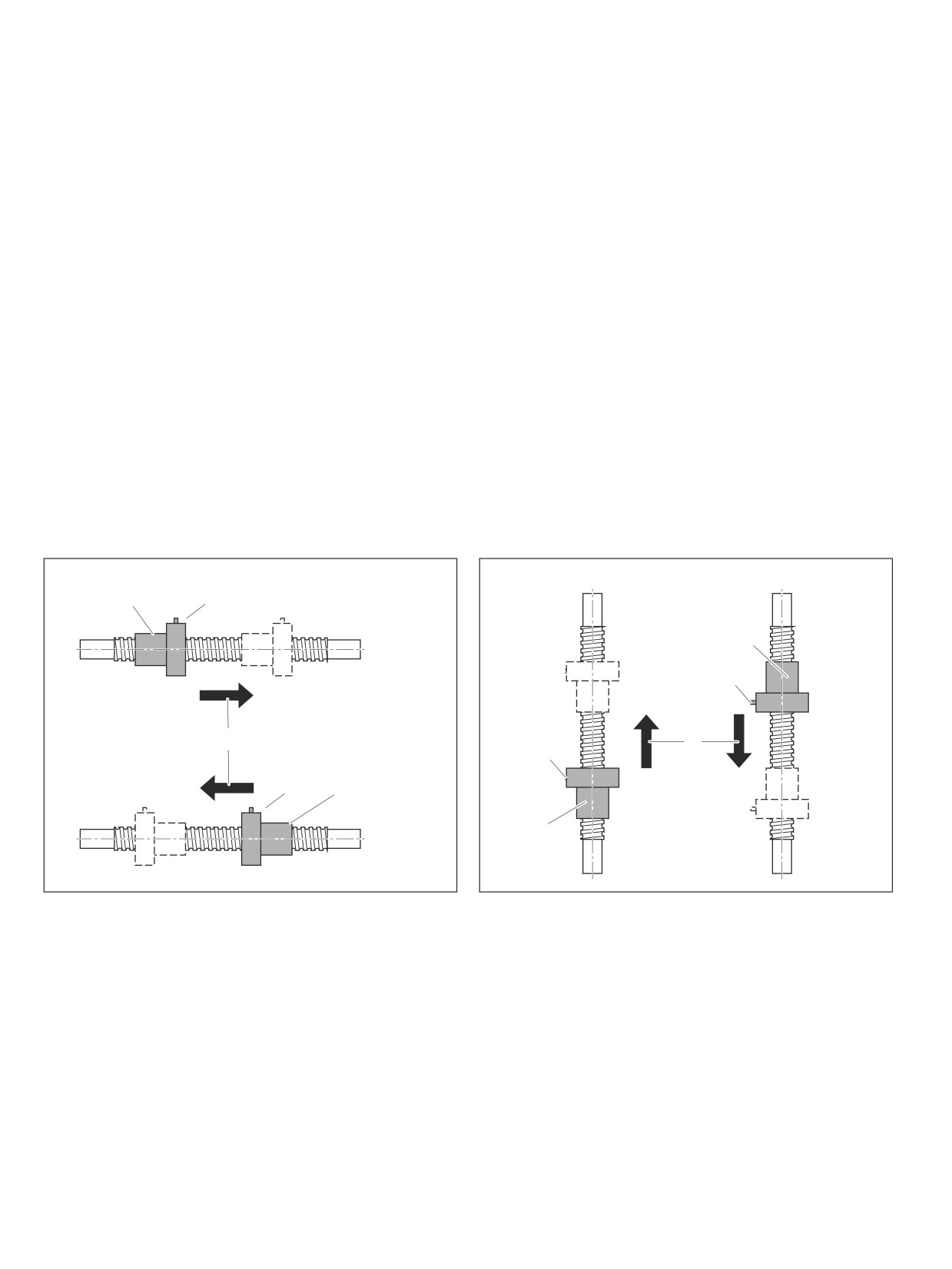
The positioning and traversing instructions in
the illustration below must be complied with.
Positioning and traversing instructions
Horizontal mounting position
Vertical mounting position
1
2
1
2
3
3
2
2
1
1
1
Position of the nut during lubrication
2
Flange with lube port (if installed horizontally, the port should be at the top if possible)
3
Direction of travel after lubrication. Traversing path should be at least 3x the nut length.
Relubricating the Ball Screw Assemblies
Apply the relubrication quantity according to
The pulse count that is needed for this is the
The lubricant cycle time can then be obtained
Table “Amount of lubricant for oil lubrication”
integer quotient of the relubrication amount
by dividing the relubrication interval by the
on page 167 to the lube port until the speci-
according to table “Amount of lubricant for
calculated pulse count.
fied relubrication interval in the diagrams on
oil lubrication” on page 167 and the piston
In this connection, you must comply with the
page 167 has been reached.
distributor size.
nut position and traversing path shown in
In this connection, you must ensure that the
the “Positioning and traversing instructions”
smallest piston distributor size of 0.03 cm3 is
illustration.
not fallen short of.
167
Lubrication
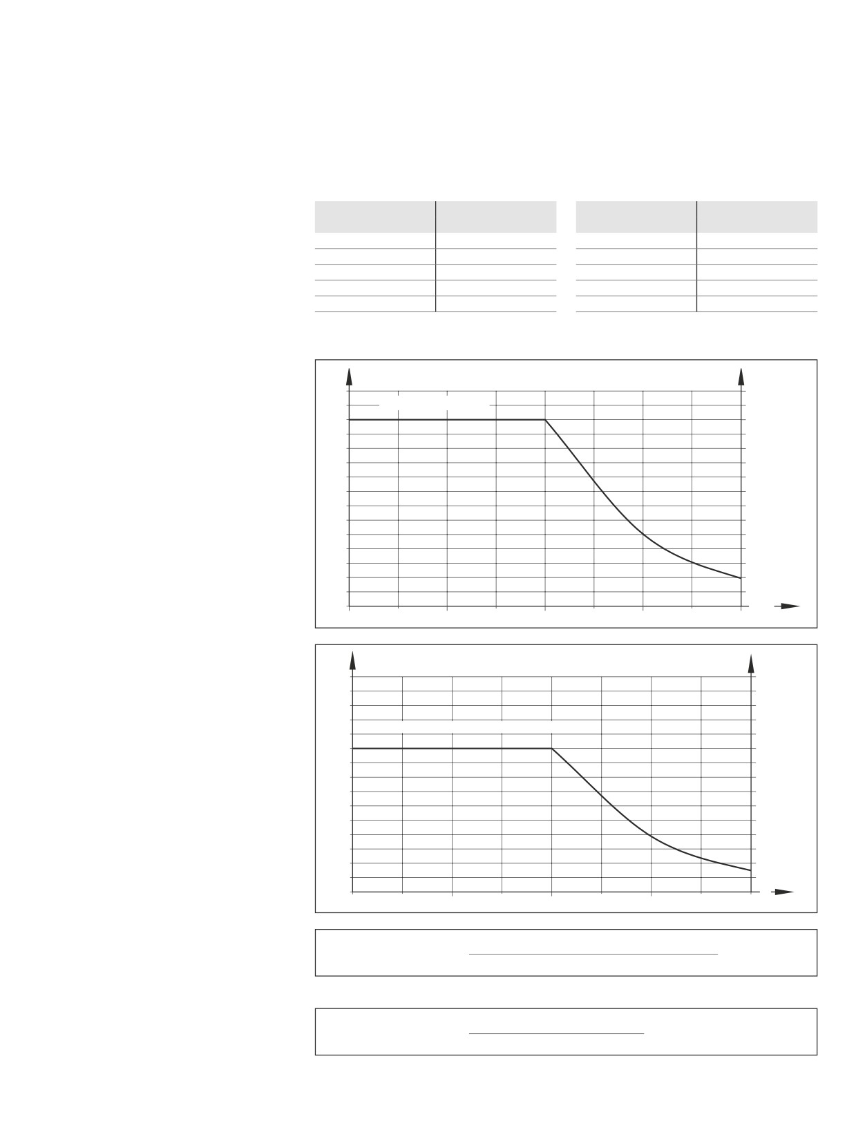
Amount of lubricant for oil lubrication
Nominal diameter
Initial lubrication
Nominal diameter
Relubrication
Note:
d0 (mm)
Ve (cm3)
d0 (mm)
Vn (cm3)
In the case of double-threaded FED-E-B
6 / 8 / 12 / 16
0.3
6 / 8 / 12 / 16
0.03
single flange nuts and oil lubrication, the
20 / 25 / 32
0.6
20 / 25 / 32
0.06
values in the tables do not apply!
40
2.0
40
0.40
Please consult with us!
50 / 63
4.0
50 / 63
0.80
80
8.0
80
1.60
Load-dependent lubrication in the case
s
(M revolutions)
s (h)
of oil lubrication with single-line piston
1,5
11,5
distributor systems (“dry axes”)
1,4
Ø 6,Ø 8, Ø 12, Ø 16
10,8
1,3
10,0
1,2
9,2
1,1
8,5
1,0
7,7
This applies to the following conditions:
0,9
6,9
--
Lubricating oil is Shell Tonna S 220
0,8
6,2
-–
No exposure to media
0,7
5,4
-–
Standard seals
0,6
4,6
-–
Driven screws
0,5
3,8
-–
Not mission critical operation
0,4
3,1
-–
Ambient temperature: T = 20 to 30 °C
0,3
2,3
0,2
1,5
0,1
0,8
F
m/C
s
= relubrication interval
0,0
0,0
0
0,1
0,2
0,3
0,4
in millions of revolutions
106 rev.
or hours
(h)
C = dynamic load rating
(N)
s
(M revolutions)
s (h)
Fm = average load
(N)
1,5
15
1,4
14
Notes
1,3
13
The load ratio Fm/C is the quotient of the
1,2
12
Ø 20, Ø 25, Ø 32, Ø 40, Ø 50, Ø 63, Ø 80
average load Fm and the dynamic load
1,1
11
rating C (see “Calculation”).
1,0
10
0,9
9
0,8
8
0,7
7
The relubrication interval s is defined either
0,6
6
by the number of revolutions in millions or
0,5
5
the operating time in h.
0,4
4
The value that is reached first defines the
0,3
3
lubrication interval.
0,2
2
0,1
1 Fm/C
0
0
0
0,1
0,2
0,3
0,4
Conversion of the relubrication interval s
s in millions (of revs) · lead P (mm)
from millions of revolutions to kilometers:
s in kilometers =
106
Example:
1.3 · 106 (revs) · 16 (mm)
s in kilometers =
= 20.8 km
106

168
Screw Assemblies | Ball Screw Assemblies BASA
Lubrication
Oil lubrication with a single-line piston distributor system
Notes
When using a single-line distributor system, you must ensure that the smallest piston distributor size of 0.03 cm3 is not fallen short of.
We recommend using piston distributors from SKF. They should be installed as close as possible to the lube ports of the Ball Screw
Assembly nut.
Long lines and small line diameters should be avoided, and the lines should be laid on an upward slant.
If other consumers are connected to the single-line centralized lubrication system, the weakest link in the chain determines the lubrication
cycle time.
In this connection, please note the general lubrication information on page 157.
Design example of lubrication a typical two-axis application using central lubrication
X axis
Component or characteristic value
Specifications
Ball Screw Assembly
FEM-E-S 32x10Rx3.969-5; C = 38000 N; Part no.: R 1512 340 13 (page 34)
Average load.
Fm = 9 510 N
Stroke
1,000 mm
Average speed
nm = 1,000 rpm
Ambient temperature
20 to 30 °C
Mounting orientation
Horizontal
Lubrication
Single-line distributor system for all axes with Shell Tonna S 220 oil
Exposure
No exposure to media, chips, dust
Design sizes
Design
Sources of information
1. Normal stroke or short stroke
Normal stroke: Stroke > nut length L; 1,000 mm > 77 mm!
For short stroke information, see page 141, for L
i.e. normal stroke applies!
see page 34
2. Initial lubrication amount
Initial lubrication amount:
See basic lubrication on page page 160
At the factory with Dynalub 510
3. Relubrication amount
Relubrication amount: 0.06 cm3
Relubrication amount from table page 160
4. Mounting orientation
Pay attention to the positioning and traversing instructions
see “Positioning and traversing instructions” on page 158
for the horizontal mounting orientation!
5. Piston distributor size
Permitted piston distributor size: 0.03 cm3
see page 159
6. Number of pulses
0.06 cm3
Relubrication amount
Number of pulses
=
= 2
Number of pulses =
0.03 cm3
Permissible piston distributor size
7. Load ratio
9,510 N
Load ratio
=
= 0.25
Load ratio
= Fm
38,000 N
C
Fm and C from specifications
8. Relubrication interval
Relubrication interval: 0.38 · 106 revs or every 3.8 h
From diagram on page 159 167 with a load ratio of 0.25
9. Effective relubrication interval
Since at nm = 1,000 rpm the 0.38 · 106 revs is only
nm from specifications is the effective relubrication
reached after 6.33 h, the read-off 3.8 h is effective as the
interval, see the “Note” on page 165
lubrication interval.
10. Lube cycle
4 h
Eff. Relubrication interval
Lube cycle =
= 2 h
Lube cycle =
2
Number of pulses
Interim result
In the case of the X-axis, the system must supply the nut of the Ball Screw Assembly with a minimum amount of 0.03 cm3
(X-axis)
of Shell Tonna S 220 every two hours.

169
Lubrication
Y axis
Component or characteristic value
Specifications
Ball Screw Assembly
FEM-E-C 16x16Rx3-3; C = 11,200 N; Part no.: R 1502 060 65 (page 36)
Average load.
Fm = 1,200 N
Stroke
500 mm
Average speed
nm = 1,500 rpm
Ambient temperature
20 to 30 °C
Mounting orientation
Horizontal
Lubrication
Single-line distributor system for all axes with Shell Tonna S 220 oil
Exposure
No exposure to media, chips, dust
Design sizes
Design
Sources of information
1. Normal stroke or short stroke?
Normal stroke: Stroke > nut length L; 500 mm > 61 mm!
For short stroke information, see page 141, for L see
i.e. normal stroke applies!
page 36
2. Initial lubrication amount
Initial lubrication amount:
See basic lubrication on page page 164
At the factory with Dynalub 510
3. Relubrication amount
Relubrication amount: 0.03 cm3
Relubrication amount from table page 167
4. Mounting orientation
Pay attention to the positioning and traversing instruc-
see “Positioning and traversing instructions” on page 166
tions for the horizontal mounting orientation!
5. Piston distributor size
Permitted piston distributor size: 0.03 cm3
see page 164
6. Number of pulses
0.03 cm3
Relubrication amount
Number of pulses
=
= 1
Number of pulses =
0.03 cm3
Permissible piston distributor size
7. Load ratio
1,200 N
Load ratio
=
= 0.11
Load ratio
= Fm
11,200 N
C
Fm and C from specifications
8. Relubrication interval
Relubrication interval: 1.3 · 106 revs or every 10 h
From diagram on page 167 with a load ratio of 0.11
9. Effective relubrication interval
Since at nm = 1,500 rpm the 1.3 · 106 revs is only
nm from specifications is the effective relubrication inter-
reached after 14.4 h, the read-off 10 h is effective as the
val, see the “Note” on page page 165
lubrication interval.
10. Lube cycle
10 h
Eff. relubrication interval
Lube cycle =
= 10 h
Lube cycle =
1
Number of pulses
Interim result
In the case of the Y-axis, the system must supply the nut of the Ball Screw Assembly with a minimum amount of 0.03
(Y-axis)
cm3 of Shell Tonna S 220 every ten hours.
Final result
Since the axes in this example are both to be supplied by a single-line distributor system, the X-axis - with its lower
(Two-axis lubrication)
(two-hour) lubrication cycle - determines the overall lubrication cycle of the system, i.e. the Y-axis is lubricated
every two hours too.

170
Screw Assemblies | Ball Screw Assemblies BASA
Lubrication
Lubricants
Dynalub high-performance lubricant for linear motion technology
(Approved in the countries of the EU only; not approved outside of the EU)
Product description of Dynalub 510
Dynalub 510 is a lithium-based high-perfor-
Application area
mance grease of NLGI grade 2 that has been
Under conventional environmental condi-
Part number
Packaging unit
specially designed for linear motion technol-
tions, this ground-fiber, homogeneous grease
R3416 037 00
1 x 400 g
ogy applications. It is characterized by its
is ideally suited for the lubrication of linear
R3416 035 00
Hobbock 25 kg
good water resistance and corrosion protec-
elements:
tion properties and can be used at tempera-
--
At loads of up to 0.5 Cdyn
tures ranging from -20 °C to +80 °C.
--
Also with short-stroke applications ≥ 1 (mm)
Chemical composition
Mineral base oil, special lithium soap, active ingredients
Technical data
Identification
KP2K-20
DIN 51 825
Appearance
Light brown-beige, ground-fiber
For additional information, see the “Dynalub
Service temperature range
-20 °C to +80 °C
510 safety data sheet”
NLGI grade
2
R310DE 2052 (2004.04)
Worked penetration
265-295 1/10 mm
DIN ISO 2137
Water resistance
0-60, 1-90
DIN 51 807 T1
Melting point in °C
> 165
DIN ISO 2176
Flash point in °C
> 200 base oil
DIN ISO 2592
Basic oil viscosity
100 mm2/s 40 °C
DIN 51 562
10 mm2/s 100 °C
Flow pressure at -20 °C
< 1,400 hPa
DIN 51 805
EMCOR test
0/0
DIN 51 802
Density at +25 °C
Approx. 0.92 g/cm3
DIN 51 757
Copper corrosion
2 (24 h/120 °C)
DIN 51 811
Four ball tester welding load
> 2,000 N
DIN 51 350 T4
Four ball tester impression diameter
0.93 (400 N, 1 h)
DIN 51 350, part 5
Shelf life in container
2 years
Product description of Dynalub 520
Dynalub 520 is a lithium-based high-perfor-
Application area
mance grease of NLGI grade 00 that has
Under conventional environmental condi-
Part number
Packaging unit
been specially designed for linear motion
tions, this ground-fiber, homogeneous
R3416 043 00
1 x 400 g
technology applications. It is characterized
grease is ideally suited for the lubrication of
R3416 042 00
Bucket 5 kg
by its good water resistance and corrosion
linear elements in miniature versions and for
R0419 090 01
5 ml maintenance kit
protection properties and can be used at
use in central lubrication systems.
temperatures ranging from -20 °C to +80 °C.
Chemical composition
Mineral base oil, special lithium soap, active ingredients
Technical data
Identification
KP00K-20
DIN 51 825
Appearance
Light brown-beige, ground-fiber
For additional information, see the “Dynalub
Service temperature range
-20 °C to +80 °C
520 safety data sheet”
NLGI grade
00
R310DE 2053 (2004.04)
Worked penetration
400-430 1/10 mm
DIN ISO 2137
Water resistance
1-90
DIN 51 807 T1
Melting point in °C
> 160
DIN ISO 2176
Flash point in °C
> 200 base oil
DIN ISO 2592
Basic oil viscosity
100 mm2/s 40 °C
DIN 51 562
10 mm2/s 100 °C
Flow pressure at -20 °C
< 700 hPa
DIN 51 805
EMCOR test
0
DIN 51 802
Density at +25 °C
Approx. 0.92 g/cm3
DIN 51 757
Copper corrosion
0-1 (24 h/100 °C)
DIN 51 811
Four ball tester welding load
1,800 N
DIN 51 350 T4
Four ball tester impression diameter
0.80 (400 N, 1 h)
DIN 51 350 T5
Shelf life in container
2 years
171
Lubrication
172
Screw Assemblies | Ball Screw Assemblies BASA
Calculation and examples
Calculation
On request, we can perform all calcula-
See “Design Calculation Service Form” on
tions to your specifications.
page 191
Average speed and average load
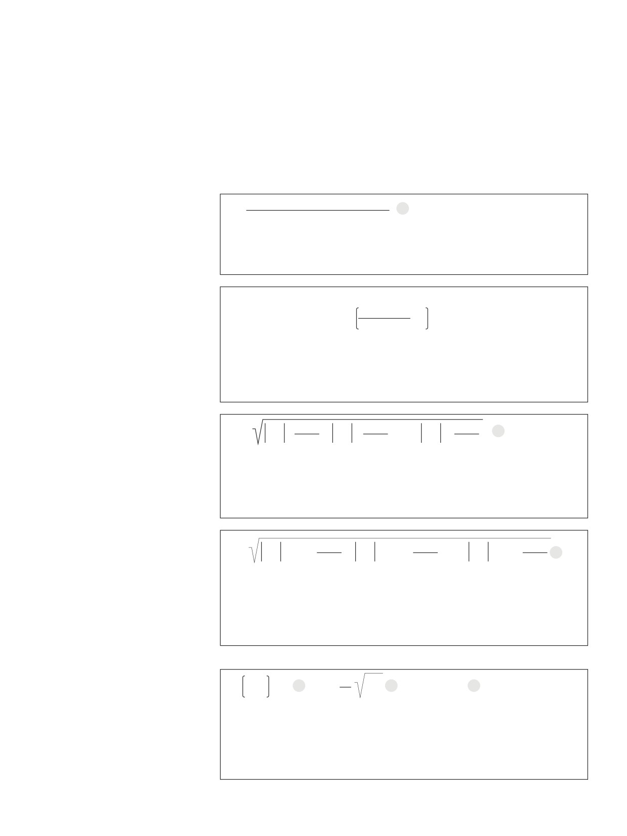
Where the operating conditions vary (fluctu-
be calculated using the average values
ating speed and load), the service life must
Fm and nm.
--
Where the speed fluctuates, the average
|n1| · qt1 + |n2| · qt2 + ... + |nn| · qtn
speed nm
is calculated as follows:
nm =
1
100%
n1, n2, ... nn
= speeds in phases 1 ... n
(rpm)
nm
= average speed
(rpm)
qt1, qt2, ... qtn = discrete time step in phases 1 ... n
(%)
The following applies to the effective
F
>
2.8 · Fpr
Feff n
= |Fn|
3
equivalent bearing load:
2
|Fn|
F
≤
2.8 · Fpr
Feff n
=
+ 1
· Fpr
2.8 · F
pr
C
= dynamic load rating
(N)
Feff n = effective equivalent axial load during phase n
(N)
Fn
= axial load during phase n
(N)
Fpr
= pre-tensioning force (see tables on pages 148/151)
(N)
-–
Where the load fluctuates and the speed
3
3
3
3
is constant, the average load Fm is cal-
qt1
qt2
qtn
Fm =
Feff 1
·
+
Feff 2
·
+ ... +
Feff n
·
2
culated as follows:
100%
100%
100%
Feff 1, Feff 2, ... Feff n = effective equivalent axial load during phases 1 ... n
(N)
Fm
= equivalent dynamic axial load
(N)
qt1, qt2, ... qtn
= discrete time step for Feff 1, ... Feff n
(%)
-–
Where both the load and the speed fluc-
3
3
3
3
tuate, the average load Fm
is calculated
|n1|
qt1
|n2|
qt2
|nn|
qtn
Fm =
Feff 1
·
·
+
Feff 2
·
·
+ ... +
Feff n
·
·
3
as follows:
nm
100%
nm
100%
nm
100%
Feff 1, Feff 2, ... Feff n
= effective equivalent axial load
during phases 1 ... n
(N)
Fm
= equivalent dynamic axial load
(N)
n1, n2, ... nn
= speeds in phases 1 ... n
(rpm)
nm
= average speed
(rpm)
qt1, qt2, ... qtn
= discrete time step for Feff 1, ... Feff n
(%)
3
Nominal service life
3
fac · C
Fm
L
fac · C
L =
·
106
4
⇒ C =
·
5
⇒ Fm =
6
Fm
fac
106
3
L
Service life in revolutions L
106
C
= dynamic load rating
(N)
Fm
= equivalent dynamic axial load
(N)
L
= nominal service life in revolutions
(-)
fac
= Correction factor for tolerance grades (see page 141)
173
Calculation and examples
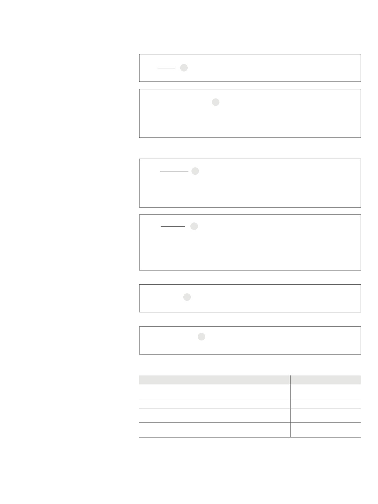
Service life in hours Lh
Lh
= Service life
(hrs)
L
Lh =
7
L
= service life in revolutions
(-)
nm · 60
nm
= average speed
(rpm)
DCmachine
= duty cycle of the machine
(%)
DCmachine
Lh machine = Lh ·
8
DCBASA
= duty cycle of the BASA
(%)
DCBASA
Lh machine
= nominal service life of the
machine
(h)
Lh
= nominal service life of the
Ball Screw Assembly
(h)
Drive torque and drive power
You must check end machining for the
maximum permissible torque
FL
= thrust force
(N)
FL · P
Mta =
9
Mp = maximum permissible drive torque
(Nm)
2000 · π · η
Mta = drive torque
(Nm)
Drive torque Mta
Mta ≤ Mp
P
= lead
(mm)
For conversion of rotary motion to linear
η
= mech. efficiency (η ≈ 0.9)
(-)
motion
Transmitted torque Mte
FL
= thrust force
(N)
FL · P · η’
for conversion of linear motion into rotary
Mte =
10
2000 · π
motion:
Mp = maximum permissible drive torque
(Nm)
Mte = transmitted torque
(Nm)
Mte ≤ Mp
P
= lead
(mm)
η´
= mech. efficiency (η´ ≈ 0.8)
(-)
The dynamic drag torque must be taken into account for preloaded nut units.
Drive power Pa
Mta = drive torque
(Nm)
Mta · n
Pa =
11
n
= speed
(rpm)
9 550
Pa
= drive power
(kW)
cc
With critical applications, you must
C0
= Static load rating
(N)
S0 = C0 / (F0 max
)
12
pay attention to the information below.
F0 max = Maximum static load
(N)
S0
= Static load safety factor
(-)
Static load safety factor S0
You must verify mathematically any struc-
tural design involving rolling contact with
Design of the static load safety factor in relation to the operating conditions
regard to the static load safety factor.
Operating conditions
Static load safety factor S0
In this connection, F0 max represents the
Overhead arrangements and applications representing a high
≥ 12
maximum load amplitude that can occur,
hazard potential
which can affect the screw drive.
High dynamic load when at standstill, contamination.
8 - 12
It does not matter whether this load is
Normal design of machinery and plant without full knowledge of the
exerted only for a short period.
5 - 8
load parameters or connection details.
It may represent the peak amplitude of an
Full knowledge of all the load data.
overall dynamic loading.
3 - 5
Vibration-free operation is ensured.
For design purposes, the data shown in the
table applies.
If there are health and safety hazards, protection against falling loads must be provided
(see the chapter entitled “Arrestor nut”)
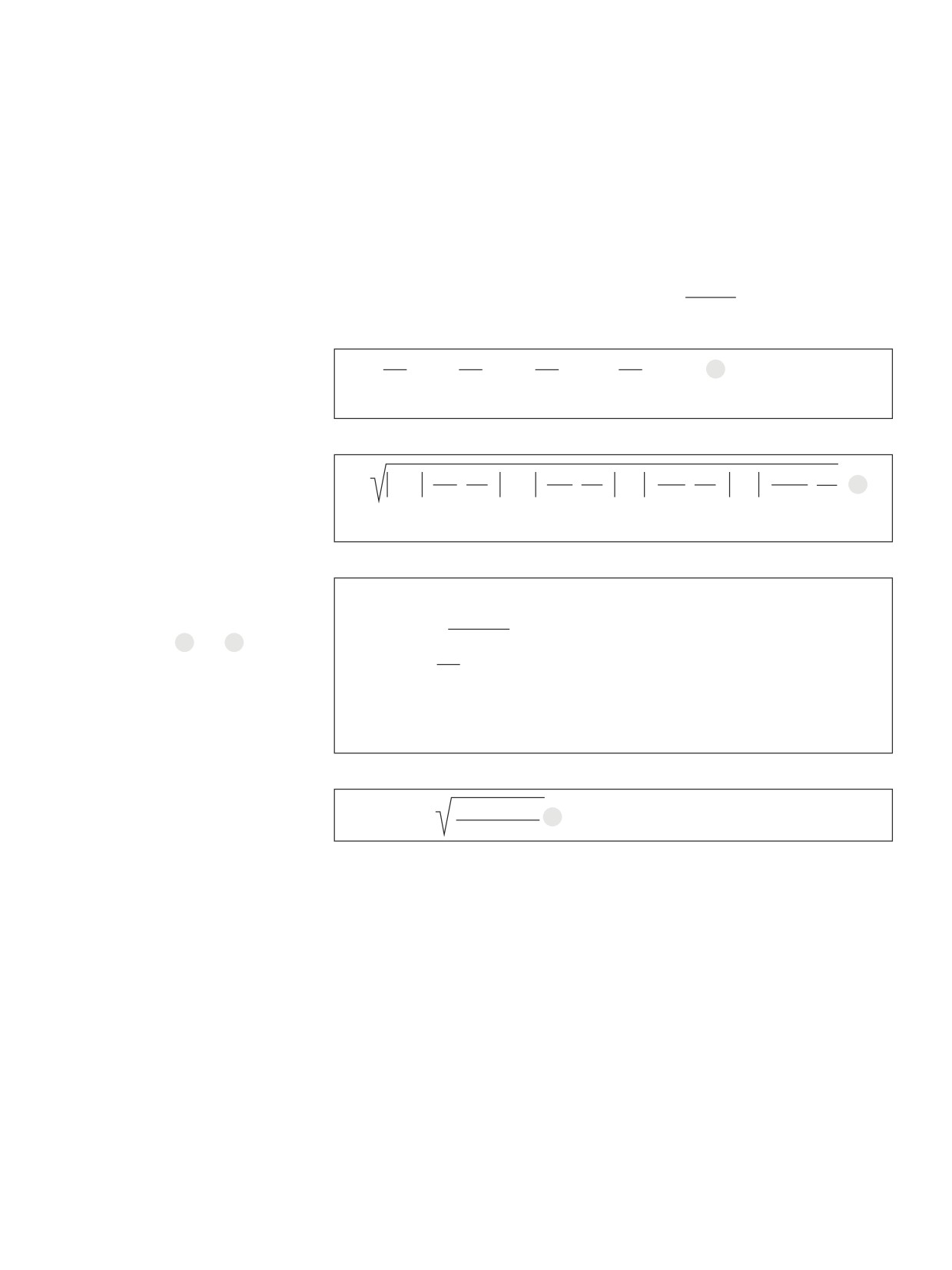
174
Screw Assemblies | Ball Screw Assemblies BASA
Calculation and examples
Calculation
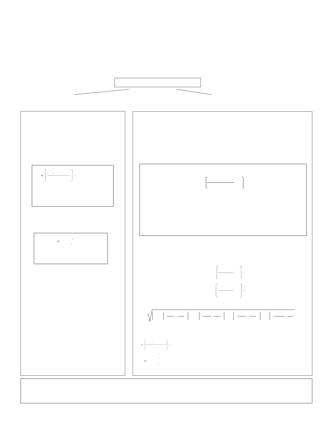
Calculation example Service life
Proposed BASA: 63 x 10
Operating conditions
F1
=
50 000 N at n1 =
10 rpm for q1 =
6% of the duty cycle
The service life of the machine should be
F2
=
25 000 N at n2 =
30 rpm for q2 =
22% of the duty cycle
40,000 operating hours with the BASA
F3
=
8 000 N at n3 =
100 rpm for q3 =
47% of the duty cycle
operating 60% of the time.
F4
=
2 000 N at n4 =
1000 rpm for q4 =
25% of the duty cycle
100%
Calculation procedure
6
22
47
25
nm =
·
|10| +
·
|30| +
·
|100| +
·
|1000|
1
100
100
100
100
Average torque nm
nm = 304 rpm
Average load Fm for variable load and
3
3
|10|
6
3
|30|
22
3 |100|
47
3 |1000|
25
variable speed
F
m =
50000
·
·
+
25000
·
·
+
8000
·
·
+
2000
·
·
3
304
100
304
100
304
100
304
100
Fm = 8 757 N
Required service life L
L
= Lh · nm · 60
(revolutions)
DCBASA
The service life L can be calculated by
Lh = Lh machine ·
DCmachine
transposing formulas
7 and
8 :
60
Lh = 40 000 ·
= 24000 h
100
L
= 24 000 · 304 · 60
L = 437,760,000 revolutions
Basic dynamic load rating C
3
437 760 000
C = 8 757 ·
5
C ≈ 66 492 N
106
Result and selection
Now a selection can be made from the
e.g. Ball Screw Assembly,
dimension tables:
size 63 x 10 R x 6-6, with preloaded
Attention:
FEM-E-S single flange nut,
Take into account the dynamic load rating
dyn. load capacity C = 106,600 N,
of the screw end bearing used!
part no. R1512 640 13,
with screw tolerance grade 7.
cc
Take into account correction factor
fac of the tolerance grade! See page 141.
175
Calculation and examples
Cross-check
Now the following can be selected from the product tables:
Size 63 x 10 R x 6-6
Backlash (C0)
Preload
(preload class C3)
FEM-E-S, with standard backlash
FEM-E-S, with preload class C3
Load rating Cdyn = 106,560 N
Load rating Cdyn = 106,560 N
correction factor fac = 0.9
Correction factor fac = 0.9
Cross-check
Pre-tensioning force = 4400 N
Service life of the selected ball
Cross-check
screw drive in revolutions
The following applies to the effective
equivalent bearing load:
3
F
>
2.8 · Fpr
= |Fn|
Feff n
0,9 106 560
3
L
106
8 757
2
|Fn|
F
≤
2.8 · Fpr
Feff n
=
+ 1
· Fpr
2.8 · F
pr
L ≈ 1314 · 106 revolutions
C
= dynamic load rating
(N)
Feff n = effective equivalent axial load during phase n
(N)
Fn
= axial load during phase n
(N)
Fpr
= pre-tensioning force (see tables on pages 148/151)
(N)
Service life in hours Lh
1 314 106
L
h
2,8 x Fpr = 2.8 x 4 440 N = 12 432 N
304
60
Lh ≈ 72,039 hours
- F1 = 50 000 N > 12 432 N !Feff1 = 50 000 N
- F2 = 25 000 N > 12 432 N !Feff2 = 25 000 N
1,5
- F3 = 8 000 N < 12 432 N !Feff3
=
8 000
4440 N = 9 355 N
12 432+1
1,5
- F4 = 2 000 N < 12 432 N !Feff4 =
2 000
4 440 N = 5 553 N
12 432+1
3
3
|10|
6
3
|30|
22
3 |100|
47
3 |1000|
25
Fm =
50000
·
·
+
25000
·
·
+
9355
·
·
+
5553
·
·
304
100
304
100
304
100
304
100
Fm = 9 485 N
3
0,9 106 560
L
106
9 485
= 1034 · 106 revolutions
6
1 034 10
L
h
= 56,689 hours
304 60
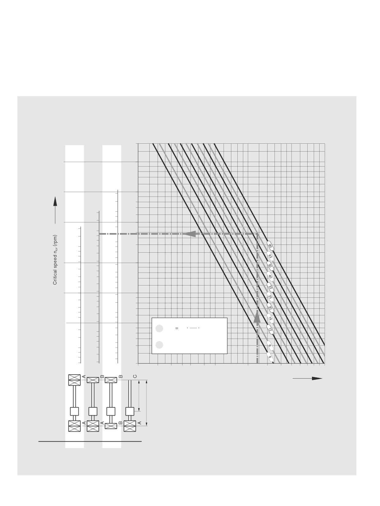
The service life of both BASAs (with standard backlash C0/with preload class C3) exceeds the required service life
of 40,000 x 60% = 24,000 hours. This means that it is possible to choose a smaller BASA,
subject to a review of it being undertaken.
176
Screw Assemblies | Ball Screw Assemblies BASA
Calculation and examples
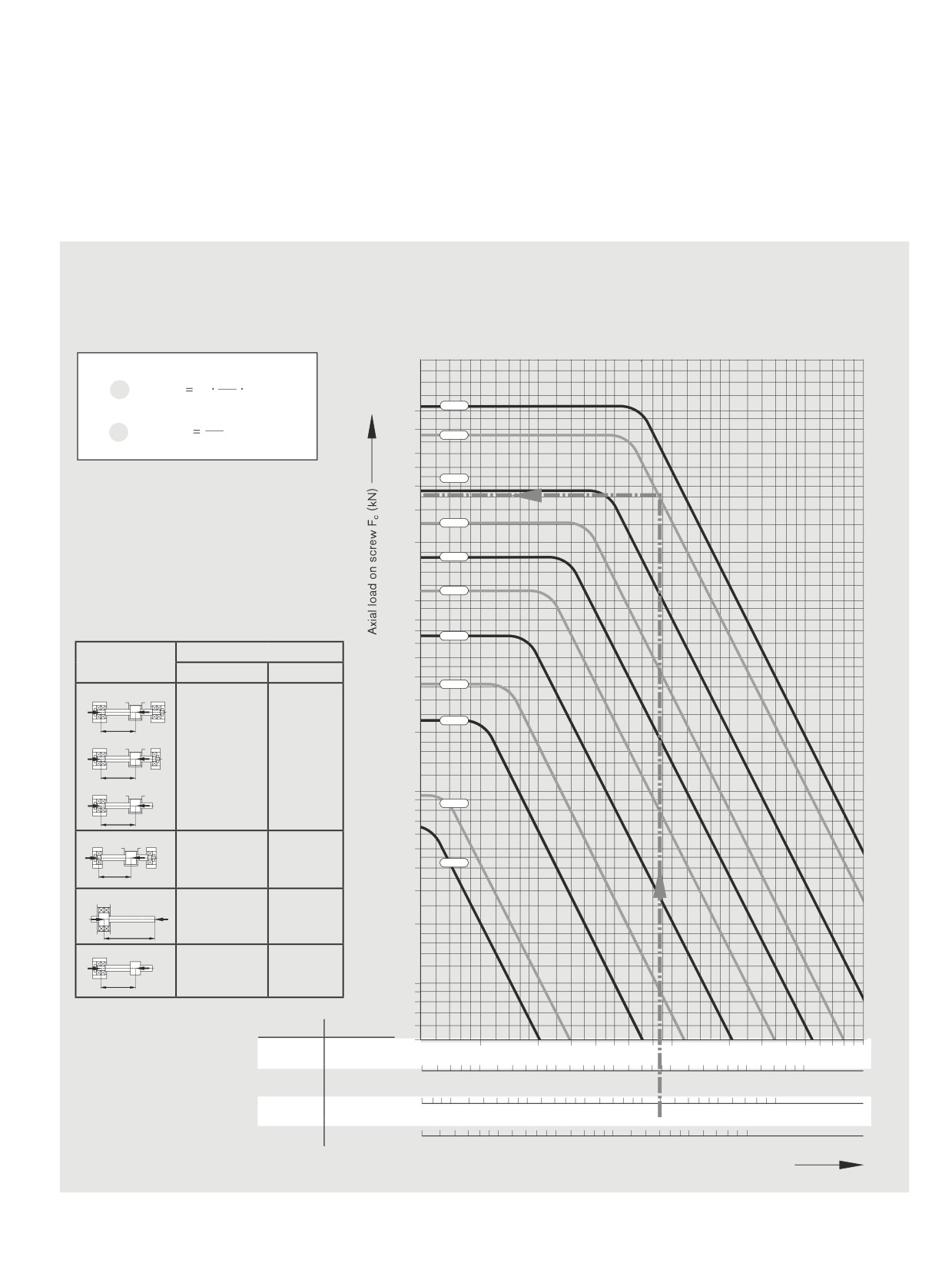
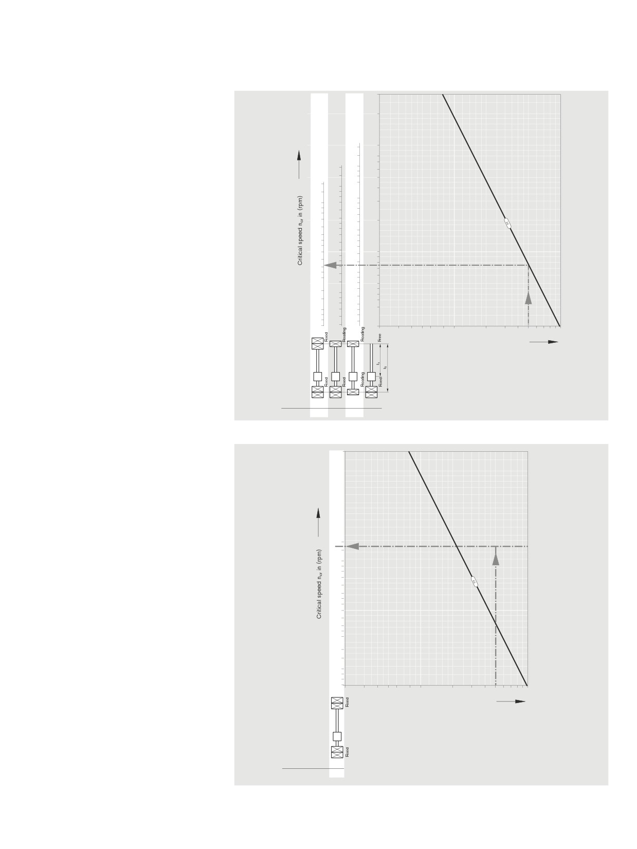
Critical speed ncr
The critical speed ncr depends on the
made for guidance by a nut with backlash.
The characteristic speed and the max. permis-
diameter of the screw, the type of end fixity,
The operating speed should not be more than
sible linear speed must be taken into account,
and the free length lcr. No allowance must be
80% of the critical speed.
see “Technical notes” on page 140.
Example
According to the graph, the critical speed
The maximum operating speed in our calculation
Screw diameter
=
63 mm
is 1850 rpm.
example of
Length lcr
=
2.4 m
The permissible operating speed is
n4 = 1000 rpm is therefore below the permissible
End fixity II (fixed bearing - floating bearing)
1850 rpm x 0.8 = 1480 rpm.
operating speed.
3000
2000
1000
3000
800
3000
2000
600
500
3000
2000
400
1000
300
2000
800
1000
200
600
800
500
1000
600
400
800
500
100
300
90
600
400
80
500
70
300
200
60
400
50
d2
7
300
13
ncr fncr
2
10
(rpm)
200
40
lcr
100
ncrp = 0.8 · ncr (rpm)
30
14
200
90
80
70
100
20
200
500
1000
2000
5000
10000
Length lcr (mm)
End fixity:
A = fixed bearing
ncr
= Critical speed
(rpm)
B = floating
lcr
ncrp = Permissible operating speed
(rpm)
bearing
ls
fncr
= Coefficient determined by bearing
C = without
d2
= Root diameter of screw ( see dimension tables)
(mm)
bearing
lcr
= Critical length for preloaded nut systems
(mm)
ls
= Bearing - bearing distance
(mm)
For non-preloaded nut systems lcr = ls
End fixity
I
II
III
IV
For screw ends Form 31, the end fixity can be assumed to be “fixed”.
fncr - value
27.4
18.9
12.1
4.3
Attention: End fixity IV (fixed-floating) - only recommended for short
overall lengths if installed horizontally. For longer overall lengths, the
floating end must be supported. Please contact our specialist department
if you have any questions.
177
Calculation and examples
Permissible axial load on screw Fc (buckling load)
The permissible axial load on the screw Fc
type of end fixity, and the effective unsup-
A safety factor of s ≥ 2 should be taken into
depends on the diameter of the screw, the
ported length lc.
account for axial loading.
Example
According to the graph, the theoretically
This therefore lies above the maximum operating load
Screw diameter
=
63 mm,
permissible axial load is 360 kN.
of F1 = 50 kN used in our calculation example.
Lead
=
10 mm,
Applying the safety factor 2 yields a
Length lc
=
2.4 m
permissible axial load on the
screw in
End fixity IV (fixed bearing - floating bearing)
operation of 360
kN :
2
= 180 kN.
d24
4
15
F
10
(N)
c fFc
lc2
80
1000
16
F
(N)
800
63
cp
Fc2
600
500
50
Fc
= Theoretically permissible axial load on
400
screw (N)
300
Fcp
= Permissible axial load on screw during
40
operation (N)
200
fFc
= Corrector value determined by bearing
32
d2
= Root diameter of screw, see dimension
tables (mm)
25
100
lc
= unsupported thread length (mm)
90
80
70
20
60
End fixity:
coefficient fFc
50
nut fixed
nut floating
40
16
A - A
30
F
F
12
l
c
20
A - B
End fixity I
End fixity IV
F
F
40.6
20.4
lc
A - C
10
9
8
F
F
8
lc
7
6
B - B
End fixity II
End fixity V
5
F
F
6
lc
20.4
10.2
4
3
A - C
F
F
End fixity III
2
lc
2.6
A - C
F
F
End fixity VI
lc
1,0
2.6
0,9
0,8
0,7
fFc value
End fixity
0,6
0,5
100
500
1000
5000
10000
End fixity:
2.6
III / VI
100
200
500
1000
5000
10000
A = fixed bearing
10.2
V
B = floating bearing
20.4
II / IV
200
500
1000
5000
10000
C = without bearing
40.6
I
200
500
1000
5000
10000
Length lcr (mm)
178
Screw Assemblies | Ball Screw Assemblies BASA
Calculation and examples
Notes on buckling
The effective buckling length lc of the screw is the maximum unsupported screw length in the direction of the force’s flow between the nut
unit and the fixed bearing (center-to-center distance) or between the nut unit and the screw end.
For buckling load calculations, the nut is taken into consideration as a bearing.
For “nut fixed,” the following conditions must be met:
--
zero-backlash nut,
-–
rigid attachment of the nut to the linear guide,
-–
the nut unit is not subjected to moment loads, i.e. a linear guide absorbs any arising moments,
-–
no distortive stresses due to external factors (for example, temperature).
In linear motion systems from Bosch Rexroth, the nut can be considered to be a fixed bearing.
If one or more of the conditions for “nut fixed” are not met, the appropriate coefficients for “nut floating” must be used instead.
Case III occurs in applications with driven nuts, for example, when the nut is stationary and the screw rotates. The nut can then be
regarded as a fixed bearing.
Case VI arises only when the nut unit is not supported by any linear guide.
Design of drive unit FAR-B-S
Fundamental advantages of systems
with driven nuts
Moment of inertia
In the case of long screws, the screw does not have to be rotated in the acceleration
phase, only the nut. The mass moment of inertia of the screw is not therefore critical. The
moment of inertia of the nut is comparatively low and it is no longer dependent on the
required stroke.
Dynamics
The intricate end bearing designs required for high dynamics, for example, fixed bearing on
both ends with angular-contact ball bearings, are no longer necessary.
Screw extenders
Since the screw is stationary, relatively little effort is needed to stretch the screw:
--
Increase in permissible axial loading (buckling load); not limited by end bearings
-–
Compensation of responses to temperature changes
-–
Increase in overall rigidity
--
Improved cooling can easily be provided using a hollow-bored screw:
Liquid cooling
-–
the stationary screw can be cooled with comparatively little effort.
-–
Controlled cooling virtually eliminates changes in length due to temperature fluctuations.
Design and manufacturing tolerances
The use of nuts with a high level of axial and radial runout precision minimizes the induced
screw vibration.
All functional components are supplied from a single source. In-house designs are no
longer needed.
Critical speed
ncr
= Critical speed
(rpm)
d2
ncrp = Perm. operating speed
(rpm)
7
–1
n
10
(min
)
cr fncr
2
fncr
= Coefficient determined
l
cr
by the bearing
ncrp = 0.8 · ncr (rpm)
d2
= For root diameter of screw,
see dimension tables
(mm)
lcr
= Critical length for preloaded
nut systems
(mm)
179
Calculation and examples
3000
Critical speed with driven screw:
In the case of driven, rotating screws,
2000
there is a critical speed that is
dependent on the different end fixities:
3000
1000
I
Fixed-fixed,
800
II Fixed-floating,
3000
2000
600
III Floating-floating,
500
IV Fixed-free.
3000
2000
400
1000
2000
300
In the case of systems with a driven screw,
800
the bending-critical speed frequently
1000
200
600
represents a limitation on speed that can be
800
500
1000
reached.
600
400
800
500
100
The rotating screw itself generates vibra-
300
600
400
90
80
tions in the system due to the deflection in
500
70
300
200
the horizontal fixity or even due to screw
400
60
50
imbalance. Depending on the free screw
300
Recommended operating
200
40
length and the speed, resonance and very
range
with a driven screw
100
ncr
200
90
30
high amplitudes can result that may destroy
80
70
the system.
100
20
200
500
1000
5000
10000
At the design stage, a safety distance
Length lcr in (mm)
of 20% to the critical speed is generally
maintained.
End fixity
I
II
III
IV
27,4
18,9
12,1
4,3
Fncr value
Critical speed with driven nut:
In the case of systems with a driven nut
and a stationary screw, self-excitation of the
screw is omitted completely with a suitable
design.
The only other things that excite vibrations
are the manufacturing precision of the rotat-
3000
ing nut or of the machine's construction
nmax
of bearing
2700
RPM
Since FAR-B-S drive units only use nuts are
2000
that have been manufactured with a high
degree of axial and radial run-out accuracy,
1000
this means that it is possible to rule out any
800
negative effect on the overall system.
Usable operating range
This means that the bending-critical speed
600
with a driven
nut
500
no longer represents a limitation.
400
The maximum speed of the bearings
300
that are used and, to a lesser extent, the
high maximum permissible rotary speed
200
(d0 x n Wert) of the nut that is used, are still
a limitation.
200
500
1000
5000
10000
Length lcr in (mm)
Note:
Applies to fixed-fixed bearing only
End fixity
I
Fncr
value
27,4
180
Screw Assemblies | Ball Screw Assemblies BASA
Calculation and examples
Design of drive unit FAR-B-S
Permissible travel speed in dependence on the nut position
Permissible travel speed with
Driven screw
a driven nut
Max. permissible travel speed in dependence on the nut position size
End fixity I fixed-fixed bearing
50x40Rx6.5 fixed-fixed bearing on driven screw
End fixity II fixed-floating bearing
120
Parameters:
--
Screw length
100
--
Screw diameter
-–
Lead
-–
End fixity
80
-–
Stretching force, negligible
-–
Max. speed of bearing
-–
D x n value of nut
60
The adjacent diagrams make clear the
40
benefits of a driven nut compared to a
“classical Ball Screw Assembly” with a
driven screw using size 50 x 40R x 6.5 as
20
an example.
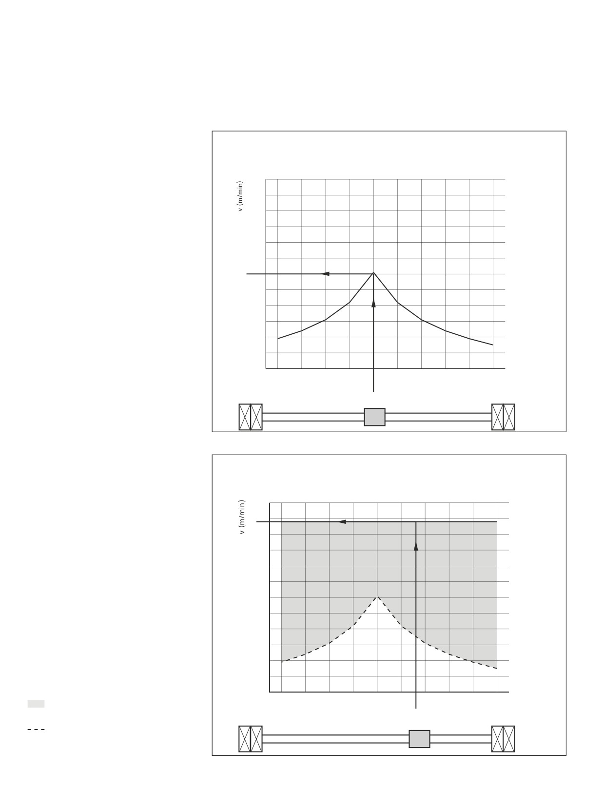
In the case of the driven screw (diagram at
the top), the maximum speed with a favor-
0
able nut position in the center of the screw
500
1000
1500
2000
2500
3000
3500
4000
4500
5000
is about 60 m/min. However, this speed is
only achieved in one position of the stroke.
Nut position (mm)
In the case of a non-central nut position,
however, it is only possible to achieve about
20 m/min, since the necessary support for
the screw is missing. This means that the
potential for a high characteristic speed of
the nut (d x n value) cannot be achieved in
Driven nut
practice.
Max. permissible linear speed
Driven nut
Size 50x40Rx6.5 with fixed-fixed bearing with driven nut
With the driven nut (diagram at the bottom
120
for end fixity I “fixed-fixed”), however, the
permissible travel speed of the driven nut
is 108 m/min regardless of the nut position
100
across the entire stroke.
In the case of end fixity II “fixed-floating”,
the floating bearing (axial displacement
80
possible) can be designed such that it is
possible to achieve a tangential gradient of
the bending line (bending angle at journal
60
area = 0).
In this case, you can also consider a float-
ing bearing end like this as being a fixed
40
bearing for the calculation.
20
0
Improved performance with driven nut
500
1000
1500
2000 2500 3000 3500 4000
4500
5000
Nut position (mm)
Driven screw