Rexroth: Screw Assemblies. Catalog (R999001185/2018-10) - page 11
151
Technical data
Size
Rigidity and dynamic drag torque of the single nuts
with preload class C1
Preload class C2
Preload class C3
Rnu
Fpr
Tp0
Rnu
Fpr
Tp0
Rnu
Fpr
Tp0
(N/µm)
(N)
(Nm)
(N/µm)
(N)
(Nm)
(N/µm)
(N)
(Nm)
d0 x P x Dw - i
Tolerance grade 3; 5; 7
Tolerance grade 3; 5; 7
Tolerance grade 3; 5; 7
63 x 10R x 6 - 6
1,100
1,780
1.120
1,250
2,660
1.68
1,460
4,440
2.800
63 x 20R x 6.5 - 3
570
1,060
0.670
650
1,600
1.01
770
2,660
1.680
63 x 20R x 6.5 - 5
950
1,680
1.060
1,080
2,520
1.59
1,280
4,200
2.640
63 x 20R x 6.5 - 8
1,250
2,090
1.320
1,430
3,140
1.98
-
-
-
63 x 40R x 6.5 - 2
390
740
0.460
440
1,110
0.70
520
1,850
1.160
63 x 40R x 6.5 - 3
580
1,070
0.670
660
1,600
1.01
780
2,670
1.680
63 x 40R x 6.5 - 6
950
1,600
1.010
1,080
2,400
1.51
-
-
-
80 x 10R x 6.5 - 6
1,290
2,170
1.730
1,460
3,250
2.60
1,700
5,420
4.340
80 x 20R x 12.7 - 6
1,430
5,250
4.200
1,620
7,880
6.31
1,910
13,100
10.510
Size
Rigidity and dynamic drag torque of the double nuts
with preload class C5
with preload class C4
Tolerance grade 3; 5; 7
Tolerance grade 3; 5; 7
Rnu
Fpr
Tp0
Rnu
Fpr
Tp0
d0 x P x Dw - i
(N/µm)
(N)
(Nm)
(N/µm)
(N)
(Nm)
16 x 5R x 3 - 4
320
860
0.06
360
1,230
0.08
20 x 5R x 3 - 4
400
1,000
0.08
450
1,430
0.11
25 x 5R x 3 - 4
470
1,110
0.11
330
1,590
0.16
25 x 10R x 3 - 4
480
1,100
0.11
440
1,570
0.16
32 x 5R x 3.5 - 4
570
1,510
0.19
640
2,160
0.28
32 x 10R x 3.969 - 5
770
2,220
0.28
860
3,170
0.41
40 x 5R x 3.5 - 5
850
2,040
0.33
950
2,910
0.47
40 x 10R x 6 - 4
760
3,500
0.56
850
5,000
0.80
40 x 10R x 6 - 6
1,150
5,050
0.81
1,280
7,210
1.15
40 x 20R x 6 - 3
570
2,650
0.42
640
3,790
0.61
50 x 5R x 3.5 - 5
1,000
2,240
0.45
1,110
3,200
0.64
50 x 10R x 6 - 4
900
3,880
0.78
1,010
5,540
1.11
50 x 10R x 6 - 6
1,350
5,580
1.12
1,510
7,970
1.59
50 x 20R x 6.5 - 5
1,180
5,300
1.06
1,320
7,570
1.51
63 x 10R x 6 - 4
1,080
4,330
1.09
1,200
6,180
1.56
63 x 10R x 6 - 6
1,620
6,220
1.57
1,800
8,880
2.24
63 x 20R x 6.5 - 5
1,420
5,870
1.48
1,590
8,390
2.11
80 x 10R x 6.5 - 6
1,870
7,590
2.43
2,070
10,800
3.47
80 x 20R x 12.7 - 6
2,130
18,400
5.88
2,380
26,300
8.41

152
Screw Assemblies | Ball Screw Assemblies BASA
Technical data
Frictional torques of the seals
Size
Dynamic drag torque
Seal torque for single
Standard seal
reinforced seal
Low-friction seal
and double nuts
d0 x P x Dw
TRD approx.
TRD approx.
TRD = 0 Nm
T0
= overall dynamic drag torque
(Nm)
(Nm)
T0
= Tp0 + TRD
6 x 1R x 0.8
-
-
TRD = dynamic drag torque of the 2 seals
6 x 2R x 0.8
-
-
Tp0 = dynamic drag torque without seals
8 x 1R x 0.8
-
-
d0
= nominal diameter
8 x 2R x 1.2
-
-
P
= lead
8 x 2.5R x 1.588
0.015
-
Dw = ball diameter
8 x 5R x 1.588
0.015
-
-
12 x 2R x 1.2
0.030
-
12 x 5R x 2
0.030
-
12 x 10R x 2
0.030
-
16 x 5R x 3
0.080
-
16 x 5L x 3
0.080
-
16 x 10R x 3
0.080
-
Note:
16 x 16R x 3
0.080
-
To measure the dynamic drag torque, see
20 x 5R x 3
0.100
-
the “Installation” section page 155.
20 x
5L x 3
0.100
-
-
20 x
10R x 3
0.120
-
-
20 x
20R x 3.5
0.120
-
20 x
40R x 3.5
0.040
-
25 x
5R x 3
0.120
0.34
25 x
5L x 3
0.120
-
-
25 x
10R x 3
0.150
0.29
25 x
25R x 3.5
0.200
0.25
32 x
5R x 3.5
0.250
0.51
32 x
5L x 3.5
0.250
-
-
32 x
10R x 3.969
0.250
0.46
32 x
20R x 3.969
0.250
0.49
32 x
32R x 3.969
0.250
0.45
32 x
64R x 3.969
0.250
0.45
40 x
5R x 3.5
0.400
0.85
40 x
5L x 3.5
0.400
-
-
40 x
10R x 6
0.400
0.91
40 x
10L x 6
0.400
-
-
40 x
12R x 6
0.400
-
-
40 x
16R x 6
0.400
-
-
40 x
20R x 6
0.400
0.54
40 x
25R x 6
0.400
0.54
-
40 x
30R x 6
0.400
0.54
-
40 x
40R x 6
0.400
0.54
50 x
5R x 3.5
0.500
-
-
50 x
10R x 6
0.600
0.95
-
50 x
12R x 6
0.600
-
-
50 x
16R x 6
0.600
-
-
50 x
20R x 6.5
0.600
0.95
-
50 x
25R x 6.5
0.700
-
-
50 x
30R x 6.5
0.700
0.95
-
50 x
40R x 6.5
0.700
-
-
63 x
10R x 6
1.200
-
-
63 x
20R x 6.5
1.200
1.40
-
63 x
40R x 6.5
1.200
1.40
-
80 x
10R x 6.5
1.400
-
-
80 x
20R x 12.7
2.200
-
-
153
Technical data
When retrofitting and changing
Standard nuts
FED nut
over the seals, please note:
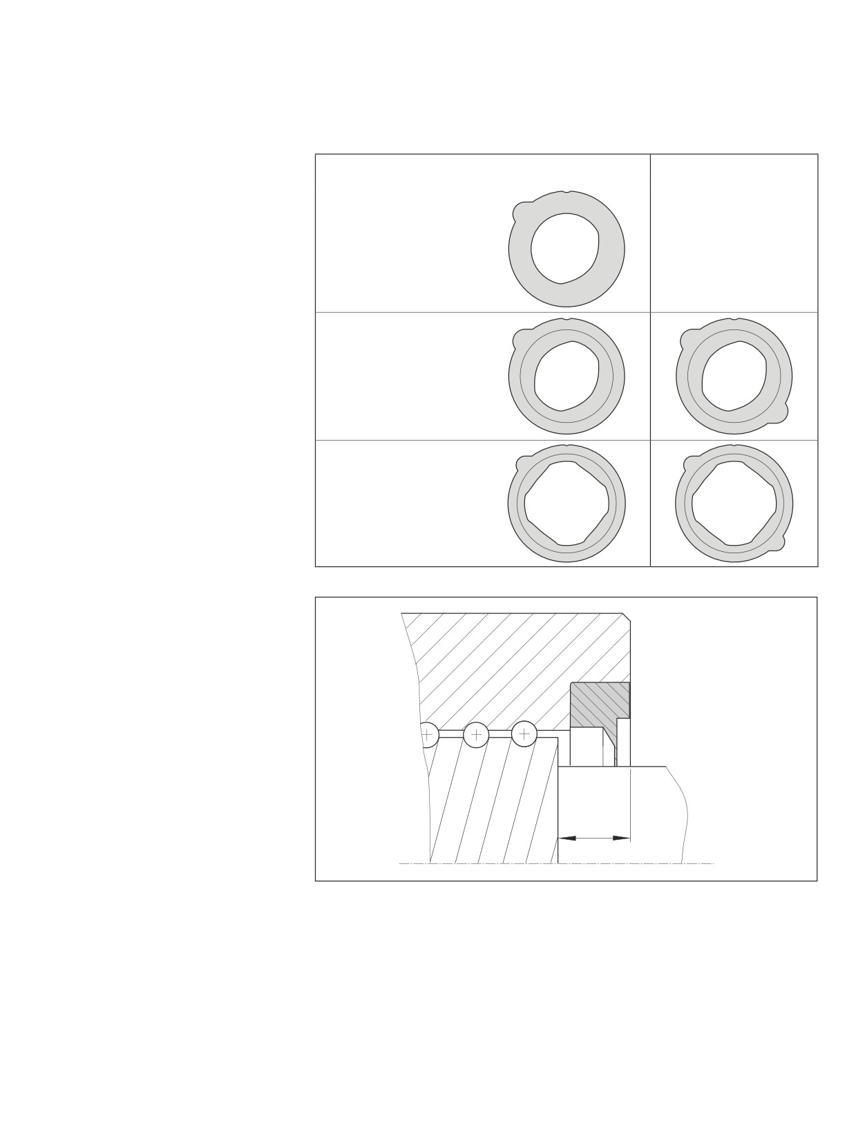
All precision screws with small leads are
Fig. 1
single-start
Single-start seal
(Figure 1). There is thus no ball raceway on
the screw.
Precision screws with higher leads,
however, are 2-start or 4-start
(Figs. 2 and 3).
“Reinforced seals” for precision screws
Fig. 2
are optionally available. This version can
Seal for the 2-start precision
be identified by the opal-green coloring of
screw with medium lead
the component and the material number.
Low-friction seals for precision screws are
available on request. This version can be
identified by the red-brown coloring of the
component and the material number.
Fig. 3
Seal for the 4-start precision
screw with high lead
Installing the seal
Position the nut on the screw according to
the Figure. Lay the wiper seal with the nose
in the recess and press until it snaps into
the groove. When turning the nut on the
screw, monitor the sealing lip and align it by
pressing on the end face if need be. Please
make sure that the sealing lip does not get
damaged.
Detailed assembly instructions are included
with the delivery.
5 - 10 mm
154
Screw Assemblies | Ball Screw Assemblies BASA
Installation
Installation
Delivery condition
Nut mounting
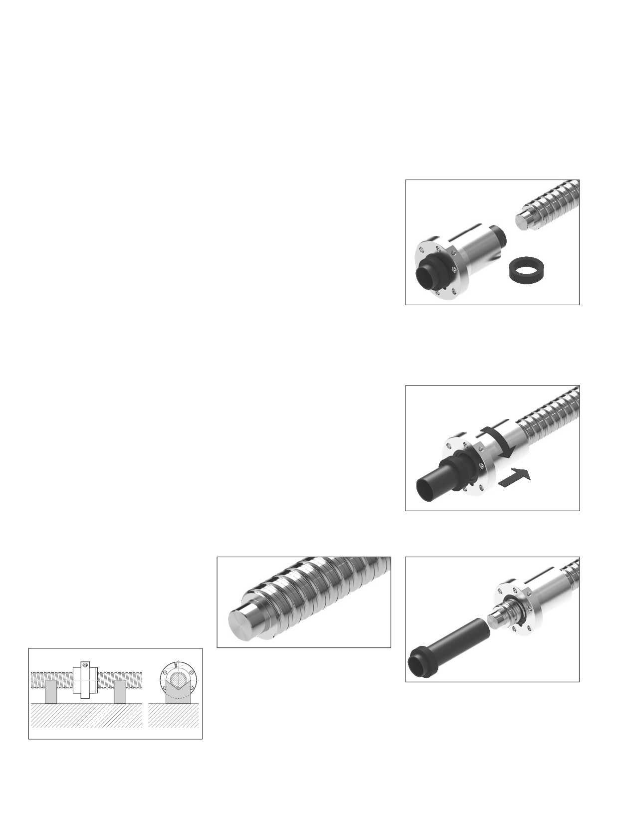
Individual mounting steps
Normally, Rexroth ball screws are supplied
Carry out installation as follows:
initially greased with Dynalub grease. This
Preloaded single nut double nut
Remove the retaining ring (! mounting
makes possible relubrication using oil or
These versions are always supplied on the
instructions) on one side of the mounting
grease. and cartridges and cans of this
ready-mounted nut unit on the screw.
arbor.
grease are available. If another lubricant
You must not disassemble the nut unit and
is used, you will need to check that it is
the screw. If this is unavoidable, please
compatible with the initial lubrication grease.
contact us.
In special cases, a Ball Screw Assembly
with only a preservative coating can be
ordered and supplied using the appropriate
ordering code.
Note: In the case of Ball Screw
Assemblies with a front lube unit, do
cc
Note
not rotate the nut and the front lube
The selected lubricant must be in the nut
unit from the screw.
before the machine is started.
Single nut with standard backlash
Push the mounting arbor with the nut to the
Cleaning
Single nut with reduced backlash
start of the thread.
Various cleaning agents can be used to
Adjustable-preload single nut
The arbor must be in contact on an axially
degrease and wash the assembly:
backlash-free basis.
--
aqueous cleaning agents
You must only mount the nut unit on an
Now, carefully turn the nut unit onto the
-–
organic cleaning agents
end-machined screw using a mounting
thread with slight axial pressure.
arbor. The screw journal is then used
cc
Note
to center the mounting arbor. In the case
Immediately after cleaning, thoroughly dry
of screw ends of Form “00”, you can use a
all parts and apply a preservative coating or
centering bore “Z” on the end face to place
anti-corrosion oil.
an auxiliary spigot in position for mounting.
In all cases, take care to observe the ap-
The external diameter of the arbor should
propriate legal regulations (environmental
be approximately 0.1 mm less than the root
protection, health and safety at work, etc.)
diameter of the screw. In most cases, you
as well as the specifications for the clean-
can use the supplied arbor with nut units. The
ing agent (e.g. handling).
start of the screw’s thread must be rounded
off carefully to avoid damage to the seal and
the individual inner parts of the nut unit.
Do not remove the mounting arbor until the
nut unit is located completely on the screw
Storage
thread.
Ball Screw Assemblies are high-quality
systems that must be treated with due care.
In order to prevent damage and contamina-
tion, the elements should not be removed
from the protective wrapping until immedi-
ately before installation. Once they have
been removed from the packaging, they
must be set down on V-shaped cradles.
The individual mounting steps are
described below.
Disassembly is carried out in the reverse
order. Be particularly careful; otherwise, the
nut or its individual internal parts could be
damaged, which would lead to premature
failure of the Ball Screw Assembly.
155
Installation
Steel/aluminum and aluminum/aluminum
Preloading of the adjustable-
Installation in the machine
material pairings
preload single nut
It is not normally necessary to remove the
Screw
Tightening torque (Nm)
Measuring of the dynamic drag torque with
preservative coating before installation.
diameter
Strength classes as per
SEM-E-S and SEM-E-C.
--
If the Ball Screw Assembly is
(mm)
DIN ISO 898
Use an adjusting screw to restrict the
contaminated, you must clean it first
8.8
10.9
12.9
clearance of the nut that is ready-mounted
(see “Cleaning”) and re-oil it
M3
1.2
1.2
1.2
on the screw such that the dynamic drag
--
Push the nut unit into the mounting bore,
M4
2.4
2.4
2.4
torque Tp0 achieves the value in the table
taking care to avoid any impact force or
M5
4.8
4.8
4.8
! page 148 (with the Ball Screw Assem-
misalignment.
M6
8.5
8.5
8.5
bly lightly oiled).
--
Tighten the mounting screws using a
M8
20.0
20.0
20.0
You must carry out the inspection across
torque wrench if necessary. Maximum
M10
41.0
41.0
41.0
the entire length of the thread; if the values
tightening torque for the steel/steel mate-
M12
70.0
70.0
70.0
are different from the ones in the table,
rial pairing (Rm ≥ 370 N/mm2), see table.
M14
110.0
110.0
110.0
correct the setting.
M16
175.0
175.0
175.0
After you make the setting, the centering
Steel/steel material pairing
M18
250.0
250.0
250.0
diameter D1 must match the values in the
Screw
Tightening torque (Nm)
M20
345.0
345.0
345.0
tables ! page 38 and 40. Cover the
diameter
Strength classes as per
head of the screw with a protective cap.
(mm)
DIN ISO 898
T
pa
= F·r
Tightening torques for fastening screws
Measure value, e.g.
F
8.8
10.9
12.9
according to VDI 2230 where
Set screw
with spring gauge
r
M3
1.3
1.8
2.1
µG = µK = 0.125
M4
2.7
3.8
4.6
M5
5.5
8.0
9.5
M6
9.5
13.0
16.0
Aligning the Ball Screw Assembly
M8
23.0
32.0
39.0
in the machine
M10
46.0
64.0
77.0
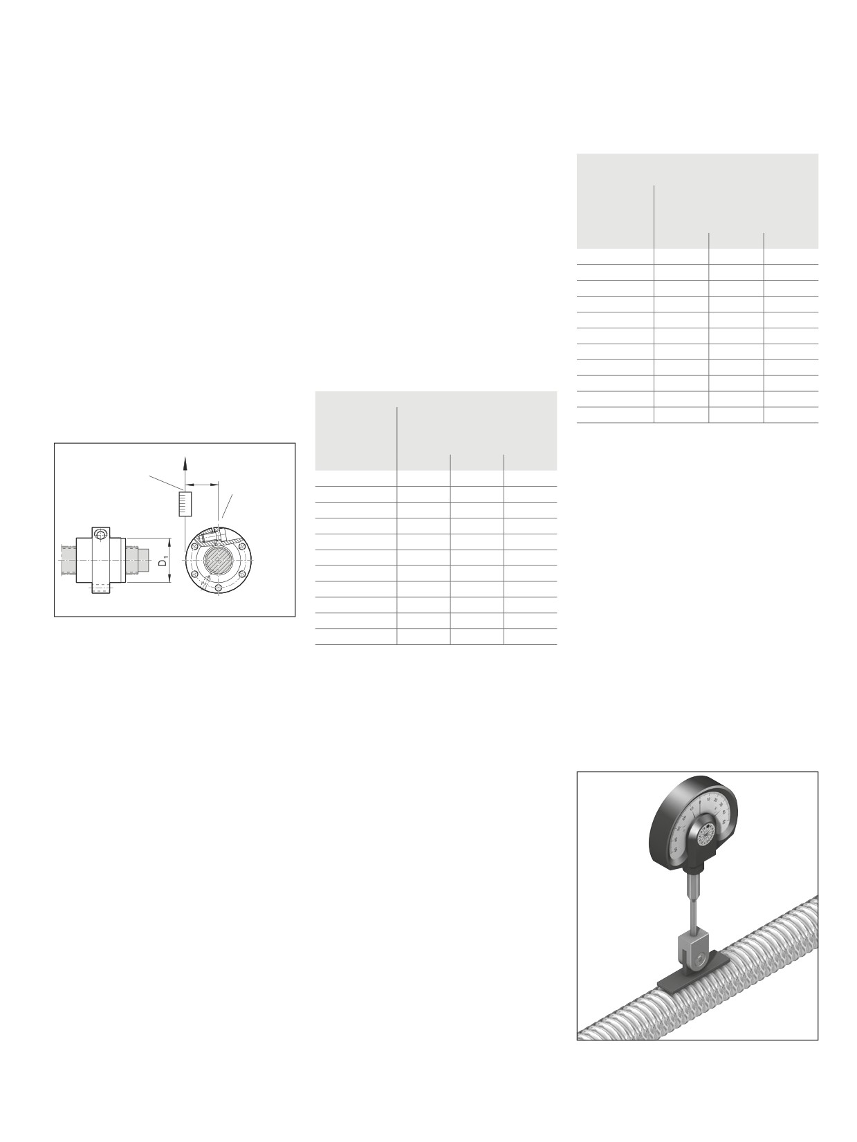
A gauge1) with a self-aligning contact pad is
M12
80.0
110.0
135.0
available from Rexroth for easy alignment of
M14
125.0
180.0
215.0
the Ball Screw Assembly.
M16
195.0
275.0
330.0
M18
280.0
400.0
470.0
Tpa
= currently measured dynamic drag
M20
390.0
560.0
650.0
torque
Two pads of different lengths are available
which can be used depending on the screw
Assembly instructions are included with
--
The maximum tightening torques speci-
lead:
each delivery. If you need additional copies,
fied in the table below apply to the steel/
--
Part number R3305 131 19
please ask us.
aluminum or aluminum/aluminum material
length 33 mm for leads < 20
pairings (Rm ≥ 280 N/mm2).
--
Part number R3305 131 21
When driving screws into aluminum, the
length 50 mm for leads > 20
length of thread engagement should be
at least 1.5 times the screw diameter.
Mounting screws
cc
Always make sure the screws
are secure where there are high screw
loads!
1) The dial gauge is not supplied
156
Screw Assemblies | Ball Screw Assemblies BASA
Installation
Installation Tolerances
cc
Note
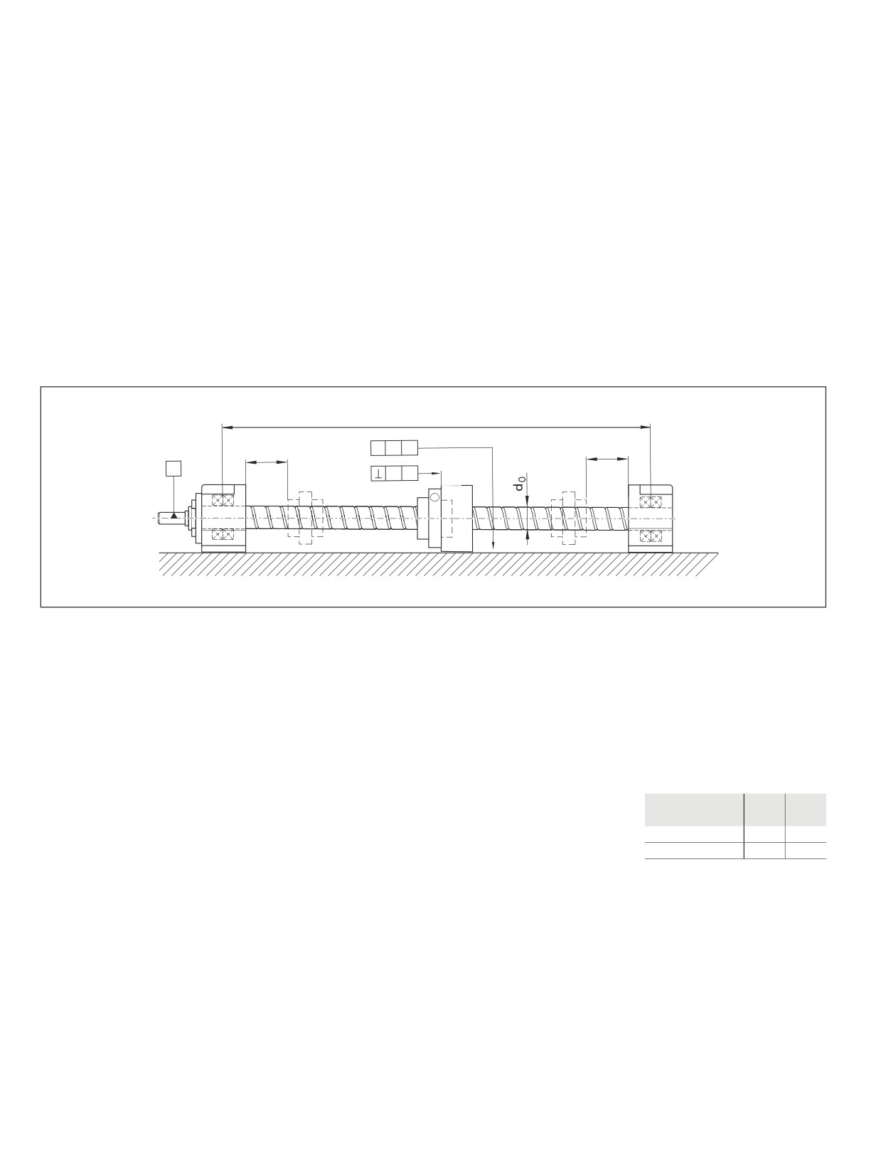
Any alignment errors can lead to premature failure of the Ball Screw Assembly, which means that they are not allowed!
To ensure that a BASA can actually achieve the calculated service life and performance, its system-related requirements and limitations
must be taken into account at the design stage. Screw assemblies are not suitable for transferring radial forces and torques, such as may
be caused by misalignments during installation. The following sections illustrate the most important principles for achieving designs that will
be compatible with the screw drive system and its requirements.
When using BASAs, the specified installation tolerances must be observed when designing and building the adjoining structures. The first
basic principle is: The higher the BASA’s precision and preload, the more accurate the adjoining structures must be.
This applies in particular to applications in which the nut travels close up to the end bearings since, in this area, the risk of distortive
stresses and therefore of additional loads is very high.
L
2 · d0
//
Y
A
2 · d
0
A
X
A
Parallelism offset and details of the rectangularity between the screw shaft axis and the location face of the nut housing.
L
= distance between end bearings
(mm)
d0
= nominal diameter of screw
(mm)
X
= permissible deviation from rectangularity:
The tolerance applies to a surface that must lie
between two planes spaced at a distance X from
each other which are perpendicular to the reference axis A.
(mm)
Y
= Permissible parallelism offset between the guide
and the Ball Screw Assembly
(mm)
Preload option
X
Y
The adjacent table shows the most important recommended tolerances for Ball Screw Assemblies as a
(mm)
(mm)
function of the preload.
Backlash
0.04
0.04
These tolerances include the rectangularity of the nut housing (or adjoining structure) relative to the
Preloaded
0.02
0.02
screw axis. The tolerances for parallelism between the guide and the Ball Screw Assembly must also
be complied with.
Minimum distance of the nut from the end bearings > 2 • d0
Any alignment errors can lead to premature breakdown of the Ball Screw Assembly!
157
Installation
Lubrication
cc
Do not use greases containing solid particles (e.g. graphite or MoS2)!
cc
If other lubricants are used, this may lead to a reduction in the relubrication intervals, the achievable travel in short-stroke
applications, and the load capacities. Possible chemical interactions between the plastic materials, lubricants and preservative
oils must also be taken into account.
cc
If your application makes greater environmental demands (i.e. cleanroom, vacuum, foodstuff application, strong or aggres-
sive metalworking fluids, or extreme temperatures) please contact us, since a special test, and possibly a special lubricant, will be
required. Please have all information about your application to hand.
cc
When using in other sectors, e.g.: food industry, clean room, vacuum etc. or at extreme temperatures, or if the lubrication is
exposed to process media, the standard initial lubrication and anti-corrosion agents used prior to shipment may not be suitable,
or they may be incompatible with the relubrication lubricant. In this case, please consult us in advance!
cc
Even under normal operating conditions, the system must be relubricated at the latest after 2 years due to aging of the
grease. Please note the reduced load ratings according to the technical notes.
Recommendation:
In general, you should not apply the lubricant all in one go; rather, apply several smaller amounts.
In the case of a short stroke, (stroke ≤ nut length, L), it is advisable to carry out a lubricating stroke more often. In this case, there
is a risk, amongst other things, that low-viscosity lubricants drop out.
Please note the information about reducing the load rating in “"Technical notes"” on page 141.
Please consult our regional centers regarding short stroke applications.
You can find your local contact person at: www.boschrexroth.com/contact
158
Screw Assemblies | Ball Screw Assemblies BASA
Lubrication
Grease lubrication With a grease gun or a progressive lubrication system in the case of Ball Screw Assemblies > Ø 12 mm
Lubricating grease
We recommend using Dynalub 510 with
Under conventional environmental conditions,
You can download product and safety
the following properties:
this ground-fiber, homogeneous grease is ideally
data sheets from our website at:
--
NLGI grade 2 lithium-based high-
suited for the lubrication of linear elements:
performance grease as per DIN 51818
--
For loads of up to 50% C
Please also observe the information on
(KP2K-20 according to DIN 51825)
-–
For short-stroke applications ≥ 1 mm
page 170.
--
Good water resistance
-–
For the permissible speed range of Ball Screw
Material numbers for Dynalub 510:
-–
Corrosion protection
Assemblies
--
R3416 037 00 (cartridge 400 g)
-–
Temperature range: -20 to +80 °C
-–
R3416 035 0 0 (hobbock 25 kg)
Initial lubrication of the Ball Screw
Assemblies (basic lubrication)
Fully assembled BASAs with a diameter
When individual parts are supplied (nut on
The positioning and traversing instruc-
greater than 12 mm are prelubricated at
mounting arbor) or with versions without basic
tions (see figure below) must be
the factory with Dynalub 510.
lubrication at the factory, you must apply double
complied with.
the quantity of lubricant stated in the “Lubricant
When using progressive lubrication
quantities - Relubrication” table via the nut’s lube
systems, ensure that all the lines and
hole before commissioning.
distributors (including the connection
to the BASA nut unit) are filled before
carrying out basic lubrication or
relubrication.
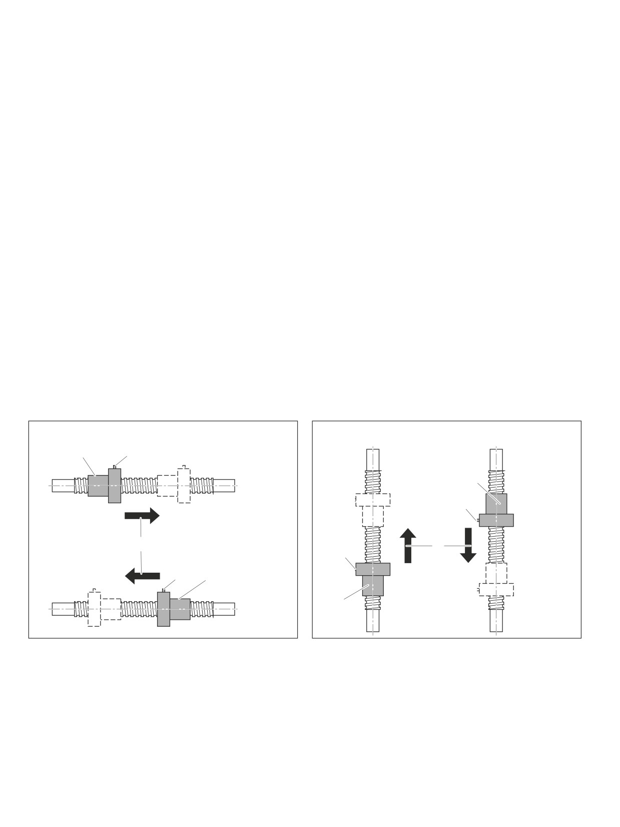
Positioning and traversing instructions
Horizontal mounting position
Vertical mounting position
1
2
1
2
3
3
2
2
1
1
1
Position of the nut during lubrication
2
Flange with lube port (if installed horizontally, the port should be at the top if possible)
3
Direction of travel after lubrication. Traversing path should be at least 3x the nut length.
Relubricating the Ball Screw Assemblies
If the relubrication interval according to the diagram on page 159 has been reached, relubricate the amount stated in Table “Amount of
lubricant for relubrication” on page 160.
In this connection, you must comply with the nut position and traversing path shown in the “Positioning and traversing instructions” illustration.
159
Lubrication
Load-dependent re-greasing intervals
in the case of grease lubrication with a
s
(M revolutions)
grease gun or a progressive lubrication
100
system in the case of Ball Screw Assem-
d0 ≤ Ø 40 mm
blies > Ø 12 mm (“dry axes”)
50
This applies to the following conditions:
--
Dynalub 510 grease or, alternatively,
Castrol Longtime PD 2,
Elkalub GLS 135/N2 grease
d0 > Ø 40 mm
--
No exposure to media
10
-–
Standard seals
-–
Driven screws
-–
Not mission critical operation
-–
Ambient temperature: T = 20 to 30 °C
s
= relubrication interval
F
m/C
in millions of revolutions (106 revolutions)
1
C = dynamic load rating
(N)
0
0,1
0,2
0,3
0,4
Fm = average load
(N)
d0 = nominal diameter
(mm)
Conversion of the relubrication interval s
s in millions (of revs) · lead P (mm)
from millions of revolutions to kilometers:
s in kilometers =
106
Example:
50 · 106 (revs) · 16 (mm)
s in kilometers =
= 8,00 km
106
Notes
The load ratio Fm/C is the quotient of the average load Fm and the dynamic load rating C (see “Calculation”).
If you are using a progressive lubrication system, please take into account the minimum metering quantity of 0.03 cm3.
In this connection, please note the general lubrication information on page 157.

160
Screw Assemblies | Ball Screw Assemblies BASA
Lubrication
Grease lubrication With a grease gun or a progressive lubrication system in the case of Ball Screw Assemblies > Ø 12 mm
Amount of lubricant for relubrication
Size
Amount of lubricant for relubrication (cm3)
FED-E-B / FEM-E-B / FEM-E-C / FEM-E-S / FEP-E-S
FAR-B-S1)
ZEV-E-S
FDM-E-C / FDM-E-S
d0 x P x Dw - i
SEM-E-C / SEM-E-S / ZEM-E-S / ZEM-E-K / ZEM-E-A
16x5Rx3 - 3
-
-
0.9
-
16x5R/Lx3 - 4
0.70
-
-
1.75
16x10Rx3 - 3
0.85
-
1.10
-
16x16Rx3 - 2
0.95
-
-
-
16x16Rx3 - 3
1.20
-
-
-
16x16Rx3 - 6
1.35
-
-
-
20x5R/Lx3 - 4
1.00
-
1.30
2.95
20x5Rx3 - 5
1.15
-
-
-
20x10Rx3 - 4
1.50
-
-
-
20x20Rx3.5 - 2
1.85
-
-
-
20x20Rx3.5 - 3
2.40
-
-
-
20x20Rx3.5 - 6
2.50
-
-
-
20x40Rx3.5 - 4
1.75
-
-
-
25x5R/Lx3 - 4
1.50
-
-
3.50
25x5Rx3 - 7
-
-
1.95
-
25x10Rx3 - 4
1.85
-
-
4.15
25x10Rx3 - 5
-
-
2.05
-
25x25Rx3.5 - 2
2.65
-
-
-
25x25Rx3.5 - 3
3.45
-
-
-
25x25Rx3.5 - 4.8
1.65
-
-
-
25x25Rx3.5 - 6
3.90
-
-
-
32x5Lx3.5 - 4
2.50
-
-
-
32x5Rx3.5 - 4
2.15
-
-
4.90
32x5Rx3.5 - 5
-
-
2.40
-
32x10Rx3.969 - 5
3.05
3.5
3.25
6.65
32x20Rx3.969 - 2
2.80
-
-
-
32x20Rx3.969 - 3
3.55
4.0
-
-
32x20Rx3.969 - 6
3.70
-
-
-
32x32Rx3.969 - 2
4.05
-
-
-
32x32Rx3.969 - 3
5.45
6.0
-
-
32x32Rx3.969 - 4.8
2.85
-
-
-
32x32Rx3.969 - 6
6.20
-
-
-
32x64Rx3.969 - 4
3.35
-
-
-
40x5Lx3.5 - 5
3.35
-
-
-
40x5Rx3.5 - 5
2.95
-
-
7.60
40x10Lx6 - 4
6.50
-
-
-
40x10Rx6 - 4
6.65
-
-
16.75
40x10Rx6 - 5
7.70
8.4
-
-
40x10Rx6 - 6
8.15
-
-
19.70
40x12Rx6 - 4
6.75
-
-
-
40x16Rx6 - 4
9.15
-
-
21.35
40x20Rx6 - 3
8.70
9.8
-
20.55
40x20Rx6 - 8
9.35
-
-
-
40x25Rx6 - 4
10.84
-
-
-
40x25Rx6 - 8
10.99
-
-
40x30Rx6 - 4
11.95
-
-
-
40x30Rx6 - 8
12.29
-
-
40x40Rx6 - 2
10.40
-
-
-
40x40Rx6 - 3
14.30
16.1
-
-
40x40Rx6 - 6
15.00
-
-
-

161
Lubrication
Size
Amount of lubricant for relubrication (cm3)
FED-E-B / FEM-E-B / FEM-E-C / FEM-E-S / FEP-E-S
FAR-B-S1)
ZEV-E-S
FDM-E-C / FDM-E-S
d0 x P x Dw - i
SEM-E-C / SEM-E-S / ZEM-E-S / ZEM-E-K / ZEM-E-A
50x5Rx3.5 - 5
4.65
-
-
11.70
50x10Rx6 - 4
-
-
-
21.90
50x10Rx6 - 6
10.75
12.2
-
25.55
50x12Rx6 - 6
11.60
-
-
-
50x16Rx6 - 6
16.15
-
-
-
50x20Rx6.5 - 3
12.65
-
-
-
50x20Rx6.5 - 5
17.35
19.5
-
34.75
50x20Rx6.5 - 8
9.90
-
-
-
50x25Rx6.5 - 4
14.20
-
-
-
50x25Rx6.5 - 6
10.45
-
-
-
50x30Rx6.5 - 4
14.73
-
-
-
50x30Rx6.5 - 8
14.81
-
-
50x40Rx6.5 - 2
15.45
-
-
-
50x40Rx6.5 - 3
20.65
23.3
-
-
50x40Rx6.5 - 6
19.15
-
-
-
63x10Rx6 - 4
-
-
-
25.55
63x10Rx6 - 6
12.15
13.8
-
30.00
63x20Rx6.5 - 3
15.45
-
-
-
63x20Rx6.5 - 5
21.35
24.0
-
43.75
63x20Rx6.5 - 8
14.35
-
-
-
63x40Rx6.5 - 2
18.90
-
-
-
63x40Rx6.5 - 3
25.40
28.7
-
-
63x40Rx6.5 - 6
26.95
-
-
-
80x10Rx6.5 - 6
19.10
-
-
66.00
80x20Rx12.7 - 6
65.50
-
-
132.75
1) Grease can be applied to the driven nut via the outer ring of the angular-contact thrust ball bearing. The only thing to observe is that the nut must stand still during the lubrica-
tion process. The nut may be positioned anywhere on the screw during this process. This easily solves the problem of a rotating lube fitting on the nut. Two lube fittings (M6)
with radial or axial access are provided. Condition on delivery: both sealed by setscrews. The desired lube port can be opened by removing the set screw.
Note: The sizes that are listed in the table are not available for all nut types.
You can find the respective size range in the chapter entitled “Nuns” from page 24 onward.
162
Screw Assemblies | Ball Screw Assemblies BASA
Lubrication
Liquid grease lubricationwith a single-line piston distributor system and
Liquid grease lubrication with Ball Screw Assemblies ≤ Ø 12 mm
Lubricating grease
We recommend using Dynalub 520 with
--
With miniature versions
the following properties:
Under conventional environmental condi-
--
Lithium-based, high-performance grease
tions, this ground-fiber, homogeneous
You can download product and safety
of NLGI grade 00 according to
grease is ideally suited for the lubrication of
data sheets from our website at:
DIN 51818 (GP00K-20 according
linear elements:
to DIN 51826)
--
In single-line one-point lubrication
Please also observe the information on
--
Good water resistance
systems
page 170.
-–
Corrosion protection
--
For loads of up to 50% C
-–
Temperature range: -20 to +80 °C
--
For short-stroke applications ≥ 1 mm
Material numbers for Dynalub 520:
-–
For the permissible speed range of
--
R3416 043 00 (cartridge 400 g)
Ball Screw Assemblies
--
R3416 042 00 (bucket 5 kg)
-–
R0419 090 01 (5 ml maintenance kit)
Initial lubrication of the Ball Screw
The positioning and traversing instructions in
Assemblies (basic lubrication)
the illustration below must be complied with.
Fully assembled BASAs with a diameter less
When individual parts are supplied (nut on
When using single-line distributor systems,
than or equal to 12 mm are prelubricated at
mounting arbor) or with versions without
care should be taken that all lines and the
the factory with Dynalub 520.
basic lubrication at the factory, you must
piston distributors (including the connection
apply double the quantity of lubricant stated
to the BASA nut) are filled before performing
in table “Amount of lubricant for relubrication”
basic lubrication or relubrication. In the case
on page 164 via the nut’s lube hole before
of Ball Screw Assemblies ≤ Ø 12 mm, it is
commissioning.
advisable to use the maintenance set.
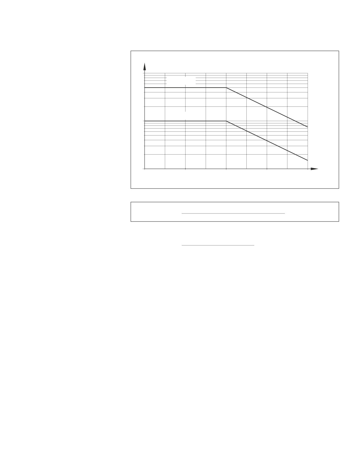
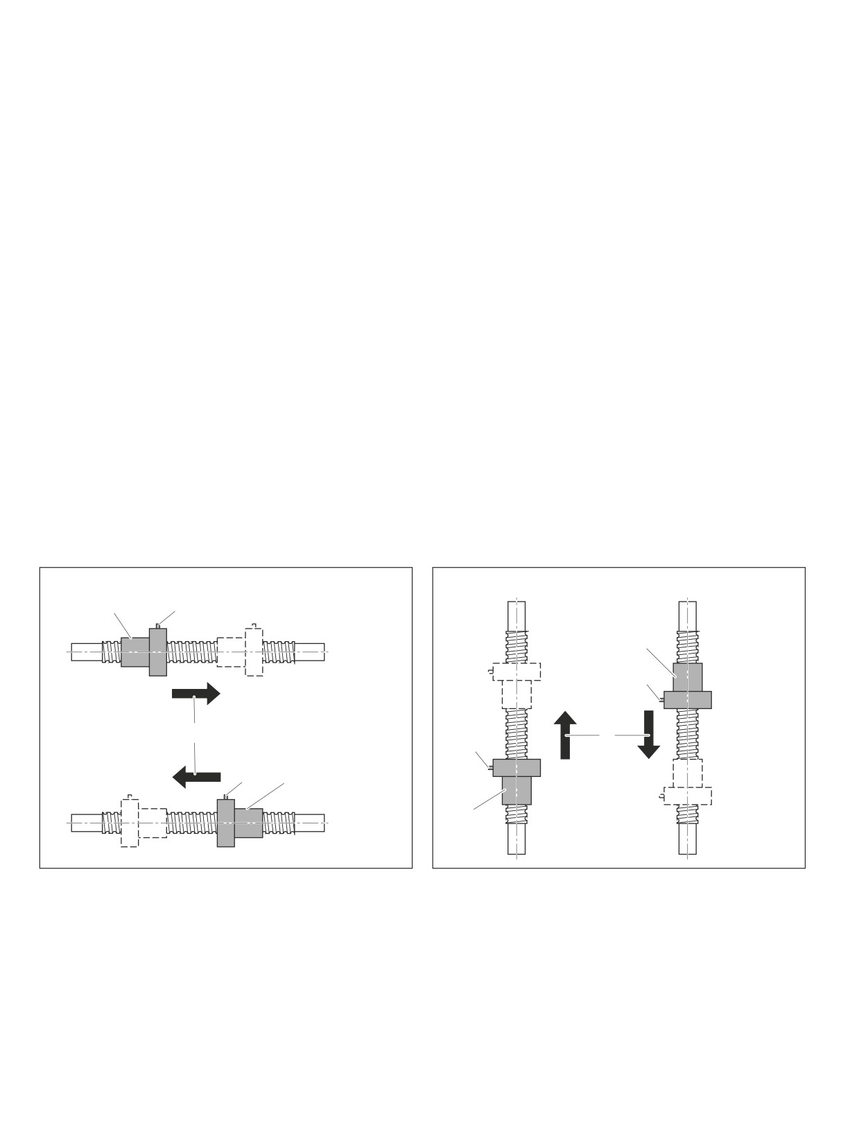
Positioning and traversing instructions
Horizontal mounting position
Vertical mounting position
1
2
1
2
3
3
2
2
1
1
1
Position of the nut during lubrication
2
Flange with lube port (if installed horizontally, the port should be at the top if possible)
3
Direction of travel after lubrication. Traversing path should be at least 3x the nut length.
Relubricating the Ball Screw Assemblies
Apply the relubrication quantity according
The pulse count that is needed for this is
to Table “Amount of lubricant for relubrica-
the integer quotient of the relubrication
The lubricant cycle time can then be
tion” on page 164 to the lube port until
amount according to table “Amount of lubri-
obtained by dividing the relubrication inter-
the specified relubrication interval shown
cant for relubrication” on page 164 and
val by the calculated pulse count.
in the diagram on page 163 has been
the piston distributor size.
In this connection, you must comply with
reached.
In this connection, you must ensure that the
the nut position and traversing path shown
smallest piston distributor size of 0.03 cm3
in the “Positioning and traversing instruc-
is not fallen short of.
tions” illustration.
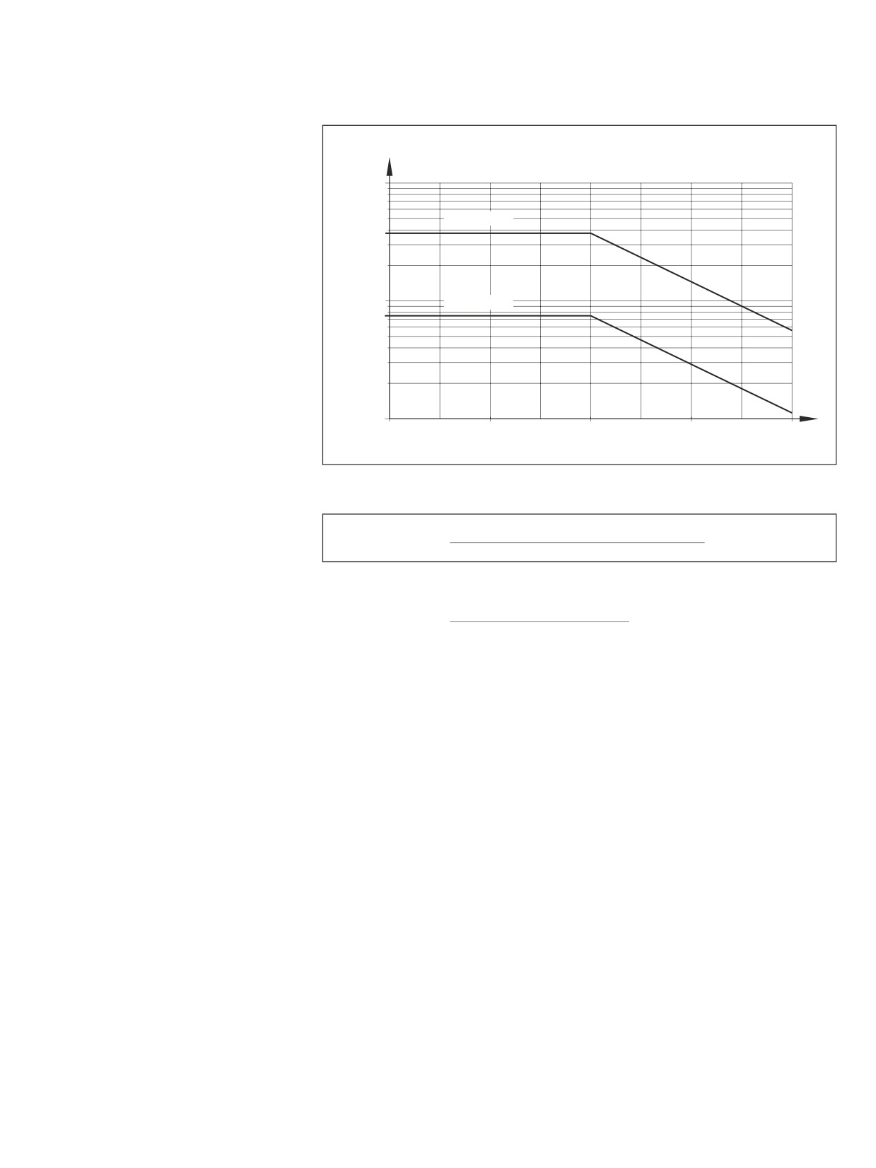
163
Lubrication
load-dependent re-greasing intervals in
the case of a single-line piston distribu-
s
(M revolutions)
tor system and liquid grease lubrication
100.0
with Ball Screw Assemblies ≤ Ø 12 mm
(“dry axes”)
d0 ≤ Ø 40 mm
This applies to the following conditions:
37.5
--
Dynalub 520 grease or, alternatively,
Castrol Longtime PD 00, Elkalub GLS
135/N00 grease
--
No exposure to media
d0 > Ø 40 mm
-–
Standard seals
7.5
--
Driven screws
-–
Not mission critical operation
-–
Ambient temperature: T = 20 to 30 °C
F
m/C
1.0
s
= relubrication interval
0
0.1
0.2
0.3
0.4
in millions of revolutions
(106 revolutions)
C
= dynamic load rating
(N)
Fm
= average load
(N)
d0
= nominal diameter
(mm)
s in millions (of revs) · lead P (mm)
Conversion of the relubrication interval s
s in kilometers =
106
from millions of revolutions to kilometers:
Example:
37,5 · 106 (revs) · 16 (mm)
s in kilometers =
= 600 km
106
Notes
The load ratio Fm/C is the quotient of the average load Fm and the dynamic load rating C (see “Calculation”).
When using a single-line distributor system, you must ensure that the smallest piston distributor size of 0.03 cm3 is not fallen
short of.
We recommend using piston distributors from SKF. They should be installed as close as possible to the lube ports of the Ball Screw
Assembly nut.
Long lines and small line diameters should be avoided, and the lines should be laid on an upward slant.
If other consumers are connected to the single-line centralized lubrication system, the weakest link in the chain determines the lubrication
cycle time.
Pumping or storage tanks for the lubricant should be fitted either with a stirrer or a follower piston to guarantee the flow of lubricant
(to avoid funneling in the tank).
In this connection, please note the general lubrication information on page 157.

164
Screw Assemblies | Ball Screw Assemblies BASA
Lubrication
Amount of lubricant for relubrication
Size
Amount of lubricant for relubrication (cm3)
FED-E-B / FEM-E-B / FEM-E-C / FEM-E-S / FEP-E-S
ZEV-E-S
FDM-E-C / FDM-E-S
d0 x P x Dw - i
SEM-E-C / SEM-E-S / ZEM-E-S / ZEM-E-K / ZEM-E-A
6x1Rx0.8-3
0.05
-
-
6x2Rx0.8-3
0.05
-
-
8x1Rx0.8-4
0.06
-
-
8x2Rx1.2-4
0.07
-
-
8x2.5Rx1.588-3
0.11
-
-
8x5Rx1.588-3
0.12
-
-
12x2Rx1.2-4
0.17
-
-
12x5Rx2-3
0.33
0.33
-
12x10Rx2-2
0.33
0.33
-
16x5Rx3-3
-
0.90
-
16x5R/Lx3-4
0.70
-
1.75
16x10Rx3-3
0.85
1.10
-
16x16Rx3-2
0.95
-
-
16x16Rx3-3
1.20
-
-
16x16Rx3-6
1.35
-
-
20x5R/Lx3-4
1.00
1.30
2.95
20x5Rx3-5
1.15
-
-
20x10Rx3-4
1.50
-
-
20x20Rx3.5-2
1.85
-
-
20x20Rx3.5-3
2.40
-
-
20x20Rx3.5-6
2.50
-
-
20x40Rx3.5-4
1.75
-
-
25x5R/Lx3-4
1.50
-
3.50
25x5Rx3-7
-
1.95
-
25x10Rx3-4
1.85
-
4.15
25x10Rx3-5
-
2.05
-
25x25Rx3.5-2
2.65
-
-
25x25Rx3.5-3
3.45
-
-
25x25Rx3.5-4.8
1.65
-
-
25x25Rx3.5-6
3.90
-
-
32x5Lx3.5-4
2.50
-
-
32x5Rx3.5-4
2.15
-
4.90
32x5Rx3.5-5
-
2.40
-
32x10Rx3.969-5
3.05
3.25
6.65
32x20Rx3.969-2
2.80
-
-
32x20Rx3.969-3
3.55
-
-
32x20Rx3.969-6
3.70
-
-
32x32Rx3.969-2
4.05
-
-
32x32Rx3.969-3
5.45
-
-
32x32Rx3.969-4.8
2.85
-
-
32x32Rx3.969-6
6.20
-
-
32x64Rx3.969-4
3.35
-
-
40x5Lx3.5-5
3.35
-
-
40x5Rx3.5-5
2.95
-
7.60
40x10Lx6-4
6.50
-
-
40x10Rx6-4
6.65
-
16.75
40x10Rx6-5
7.70
-
-
40x10Rx6-6
8.15
-
19.70
40x12Rx6-4
6.75
-
-
40x16Rx6-4
9.15
-
21.35
40x20Rx6-3
8.70
-
20.55
40x20Rx6-8
9.35
-
-
40x25Rx6-8
11.00
-
-
40x30Rx6-8
12.20
-
-

165
Lubrication
Size
Amount of lubricant for relubrication (cm3)
FED-E-B / FEM-E-B / FEM-E-C / FEM-E-S / FEP-E-S
ZEV-E-S
FDM-E-C / FDM-E-S
d0 x P x Dw - i
SEM-E-C / SEM-E-S / ZEM-E-S / ZEM-E-K / ZEM-E-A
40x40Rx6-2
10.40
-
-
40x40Rx6-3
14.30
-
-
40x40Rx6-6
15.00
-
-
50x5Rx3.5-5
4.65
-
11.70
50x10Rx6-4
-
-
21.90
50x10Rx6-6
10.75
-
25.55
50x12Rx6-6
11.60
-
-
50x16Rx6-6
16.15
-
-
50x20Rx6.5-3
12.65
-
-
50x20Rx6.5-5
17.35
-
34.75
50x20Rx6.5-8
9.90
-
-
50x25Rx6.5-6
10.45
-
-
50x30Rx6.5-6
14.80
-
-
50x40Rx6.5-2
15.45
-
-
50x40Rx6.5-3
20.65
-
-
50x40Rx6.5-6
19.15
-
-
63x10Rx6-4
-
-
25.55
63x10Rx6-6
12.15
-
30.00
63x20Rx6.5-3
15.45
-
-
63x20Rx6.5-5
21.35
-
43.75
63x20Rx6.5-8
14.35
-
-
63x40Rx6.5-2
18.90
-
-
63x40Rx6.5-3
25.40
-
-
63x40Rx6.5-6
26.95
-
-
80x10Rx6.5-6
19.10
-
66.00
80x20Rx12.7-6
65.50
-
132.75
Note: The sizes that are listed in the table are not available for all nut types.
You can find the respective size range in the chapter entitled “Nuns” from page 24 onward.