Rexroth: Screw Assemblies. Catalog (R999001185/2018-10) - page 13
181
Calculation and examples
FAR-B-S size
Speed nmax
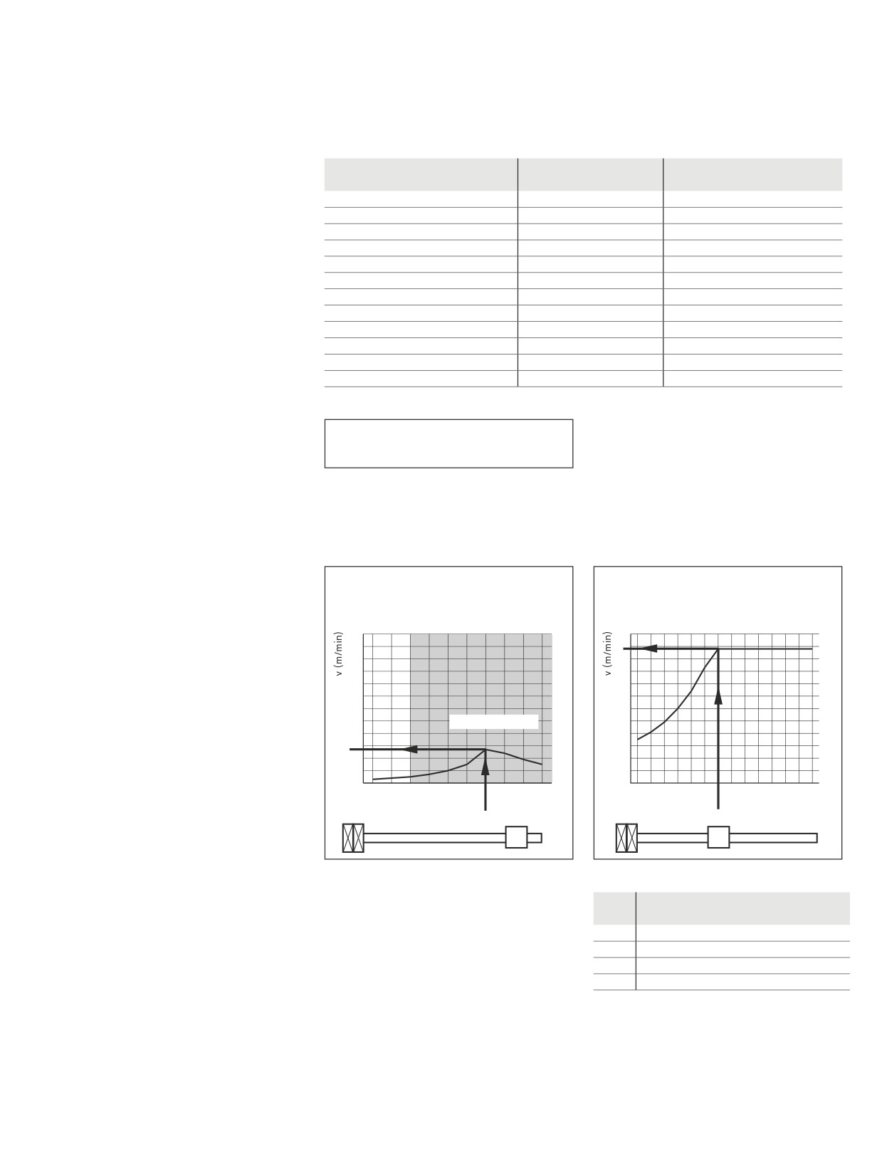
Speed vmaxFAR
For the permissible RPM and travel
d0 x P x Dw - i
(rpm)
(m/min)
speeds of FAR-B-S drive units, refer to
32 x 10R x 3.969 - 5
3,000
30
the table below:
32 x 20R x 3.969 - 3
3,000
60
32 x 32R x 3.969 - 3
3,000
96
40 x 10R x 6 - 5
2,800
28
End fixity I fixed-fixed bearing and end
40 x 20R x 6 - 3
2,800
56
fixity II fixed-floating bearing
40 x 40R x 6 - 3
2,800
112
50 x 10R x 6 - 6
2,700
27
50 x 20R x 6.5 - 5
2,700
54
50 x 40R x 6.5 - 3
2,700
108
63 x 10R x 6 - 6
2,300
23
63 x 20R x 6.5 - 5
2,300
46
63 x 40R x 6.5 - 3
2,300
92
Conversion of rotational speed to velocity
nmax · P
vmax = velocity
(m/min)
vmax =
1000
P
= lead
(mm)
nmax = rotational speed
(RPM)
End fixity III floating-floating bearing
This type of end fixity is virtually never used.
Critical speed with rotating nut and
Driven nut
Driven nut
screw clamping end fixity IV fixed-free
Max. permissible linear speed
Max. permissible linear speed
bearing
Size 50x40Rx6.5 with fixed-free bearing
Size 50x40Rx6.5 with fixed-free bearing
In the case of “fixed-free” systems with
120
120
a driven nut, it is only possible to design
the screw for short strokes. To quote an
100
100
extreme case as an example, the system
80
80
mass of the 50 x 40 screw with a length of
5,000 mm and horizontal mounting would
60
60
Cannot be used
lead to extreme static sagging of about
40
40
180 mm. You must take appropriate design
measures to ensure that considerably lower
20
20
sagging and the forces on the nut resulting
0
0
from this can be avoided,
500 1000
1500
2000 2500 3000 3500 4000 4500 5000
1
00
200
300
400
500
600
700
800
900
1
0001
100
1
2001
3001400
In this case, it is also possible with
Nut position (mm)
Nut position (mm)
FAR-B-S to consider as a limitation the criti-
cal speed at an unfavorable nut position on
the tensile restraint (see the diagram on the
right in the middle). The maximum theoreti-
cal value that can be read-off is 28 m/min
BASA
Recommended maximum length (mm)
and it cannot be used due to the deflection.
In the example diagram on the right, with
size
Lthread max
This means that for practical applications,
the recommended maximum length of
32
1,000,
you must introduce a screw length
screw Lthread max, a speed of 108 m/min is
40
1,200
limitation.
achieved at a nut position of 700 mm.
50
1,400,
63
1,600,
182
Screw Assemblies | Ball Screw Assemblies BASA
Calculation and examples
Design of drive unit FAR-B-S
Permissible torques in dependence on the nut position
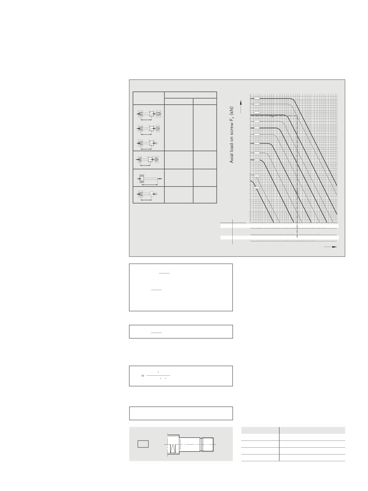
The influencing variables below limit
Buckling load
the permissible drive torque with the
End fixity:
Coefficient fFc
driven nut
1000
80
Nut fixed
Nut floating
800
63
--
Screw length
A - A
600
500
-–
Screw diameter
50
F
F
400
lc
300
-–
End fixity
40
A - B
200
-–
Stretching force
32
F
F
End fixity I
End fixity IV
lc
40.6
20.4
-–
Geometry of the screw end
25
A - C
10090
-–
Load direction; in an unfavorable case,
80
F
F
70
20
60
a compressive force on the longer screw
lc
50
40
section (buckling load)
B - B
16
30
F
F
End fixity II / IV
End fixity V
12
lc
20
20.4
10.2
A - C
10
9
8
F
End fixity III / VI
8
F
7
lc
2.6
6
5
A - C
4
6
F
F
3
End fixity VI
lc
2
2.6
1,0
0,9
0,8
0,7
End fixity
0,6
fFc value
0,5
100
500
1000
5000
10000
2.6
III / VI
100
200
500
1000
5000
10000
10.2
V
200
500
1000
5000
10000
20.4
II / IV
40.6
I
200
500
1000
5000
10000
Length lc (mm)
4
The length and diameter of the screw and
d2
Fc
= Theoretically permissible
Fc
= fFc
2
· 104 (N)
its end fixity are taken into account by the
axial load on screw
(N)
l
k
Euler buckling case.
Fcp
= Permissible axial load on screw
Fk
This yields the permissible axial load on
Fcp
=
(N)
during operation
(N)
2
the screw (see the diagram above). In
fFc
= Corrector value determined by
practice, the adjacent formulas are used for
FL
≤ Fcp
bearing
calculation.
d2
= For root diameter of screw, see
dimension tables
(mm)
lc
= unsupported thread length
(mm)
With a stretched screw, the following
Fc
FL
= operating load of the customer
(N)
Fcp
=
+ Fst
applies:
2
Fst
= stretching force of the screw
(N)
Due to an increase in temperature, the stretching force may be reduced. You must take this
effect into account when calculating Fkperm.
The drive torque that is necessary for the
FL P
Mta
= drive torque on the nut
(Nm)
Mta
operating load results from the following
2 000
π η
F
= operating load
(N)
formula:
P
= lead
(mm)
The dynamic drag torque must be taken
η
= mechanical efficiency
(approx. 0.9)
into account for preloaded nut units.
Mta ≤ MP
MP = permissible torque at the
screw journal
(Nm)
BASA size
MScperm (Nm)
Recommended maximum torque with
32
< 40
the geometry of screw end 51
51
40
< 150
50
< 180
63
< 190
183
Calculation and examples
Typical applications
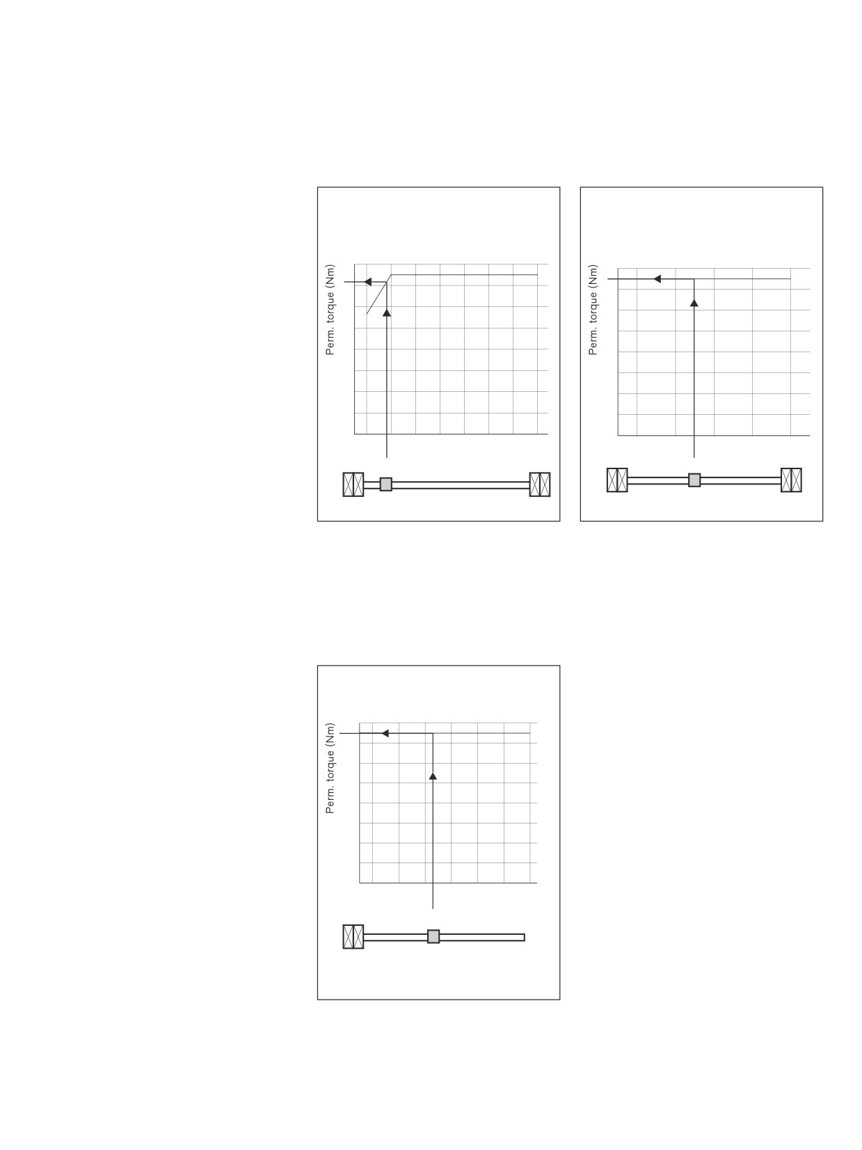
Example: A long screw axis, e.g. in the case
Example: A short screw with a machine
End fixity I fixed-fixed:
of water jet cutting, makes possible high drive
tool axis makes possible high drive torque
Parameters:
torque on a nut position-dependent basis
regardless of the nut position
--
Screw length; two cases
-–
Screw diameter
-–
End fixity in this case, fixed-fixed:
160
160
--
Stretching force ignored
140
140
(see the next page)
--
Geometry of screw end Form 51 on
120
120
two sides
100
100
--
Load direction in an unfavorable case, a
80
80
compressive force on the longer screw
60
60
section
40
40
20
20
0
0
500
1500
2500
3500
4500
5500
6500
7500
500
1000
1500
2000
2500
Lmax
Lmax
Nut position (mm)
Nut position (mm)
F
F
End fixity II fixed-floating:
Stretching is not possible.
End fixity III floating-floating
This type of end fixity is virtually never used.
End fixity IV fixed-free
Example: A short screw in a press applica-
Parameters:
tion, for example, makes possible high levels
--
Screw length
of torque
-–
Screw diameter
-–
End fixity, here fixed-free
160
-–
Stretching force, none
140
--
Geometry of screw end Form 51 on
120
one side
100
-–
Compressive load toward fixed bearing
80
60
40
20
0
200
400
600
800
1000
1200
1400
Lma
Nut position (mm)
F
184
Screw Assemblies | Ball Screw Assemblies BASA
Calculation and examples
Design of drive unit FAR-B-S
Stretching screws
Basic principles
Fixed mounting
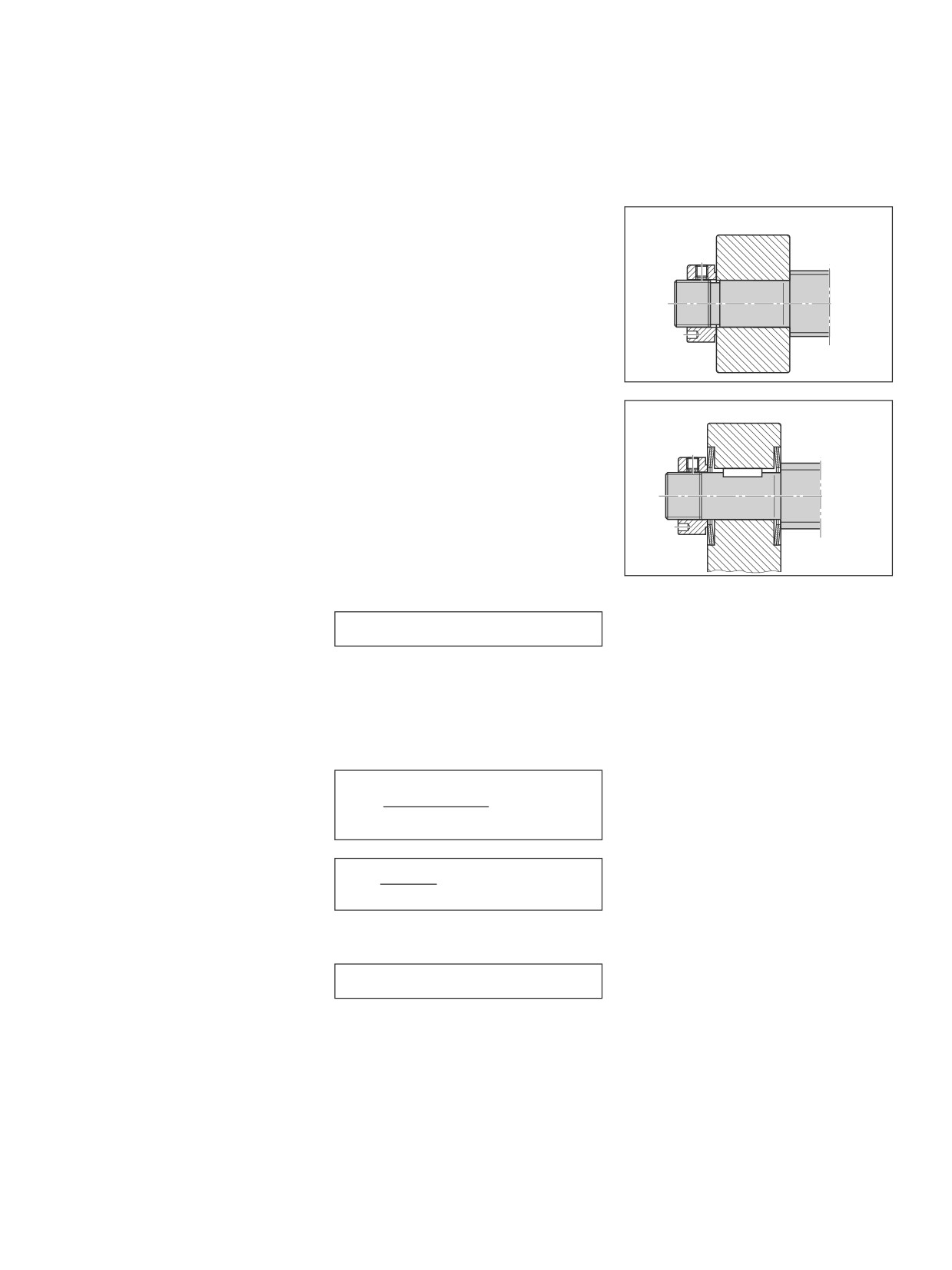
To be able to exploit the efficiency of a
The change in length and the tensile stress
system with a driven nut to the full, it is
that results due to stretching must be kept
advisable to use the type of end fixity with
to a range that is acceptable for the overall
fixing of the screw on two sides (fixed-fixed).
system. Otherwise, elastic deformation
Stretching of the screw has the following
can lead to impermissible lead deviations
positive effect on the overall system:
between the nut and the screw, which can
--
Compensation of temperature effects to
negatively impact the service life.
avoid compressive loads in the screw,
In the case of convection cooling of the
which reduces the risk of buckling
screw, stretching can maintain a maximum
temperature difference of about 10 °C.
With long, composite screws, temperature
Mounting with cup spring
compensation of 5 °C is sensible. Water
cooling of the screw is necessary at higher
temperature differences.
Linear expansion
Calculation of the linear expansion of a
∆L = Lthr · αL · (|s - |r)
∆L
= linear expansion
(mm)
screw in operation with a temperature
Lthr
= thread length
(mm)
increase.
αL
= linear expansion coefficient
(1/K)
Where αL = 0.0000115
|s
= Screw temperature
in operation
(K)
|r
= room temperature
(K)
Stretching force
Calculation of the stretching force that is
π
Fst
= stretching force
(N)
∆L · E ·
· dap2
needed for compensating the linear
4
dap
= approximation diameter
(mm)
Fst =
expansion.
Lthr
E
= Young's modulus
(N/mm2)
d0 + d2
d0
= nominal diameter
(mm)
dap =
d2
= screw core diameter
(mm)
2
Compressive stress
The compressive stress in the screw that
σc = E · (|s - |r) · αL
σc
= compressive stress due
occurs in the case of fixed mounting on two
to increased temperature
(N/mm2)
sides is calculated as shown.
Where E = 210,000 N/mm2

185
Calculation and examples
Tensile stress
For operation, the tensile stress in the
Tensile stress due to stretching that is generated in the screw
screw due to stretching must be greater
than the compressive force due to tempera-
σt
= tensile stress
(N/mm2)
Fst
ture. At the same time, the permissible
σt =
π
· dap2
tensile stress must not be exceeded.
4
σt
< σp
The maximum permissible tension
σp = 70 N/mm2
Permissible change in length
Stretching results in a change of length of
∆Lperm = perm. linear expansion
(mm)
∆Lperm = Lthr · 0.0001
the screw, which causes a change in the
Lthr
= thread length
(mm)
geometry of the screw and the raceway
geometry. To avoid negative effects on the
service life of the Ball Screw Assembly, you
∆L ≤ ∆Lperm
must check it.
186
Screw Assemblies | Ball Screw Assemblies BASA
End Bearings
Design notes, installation
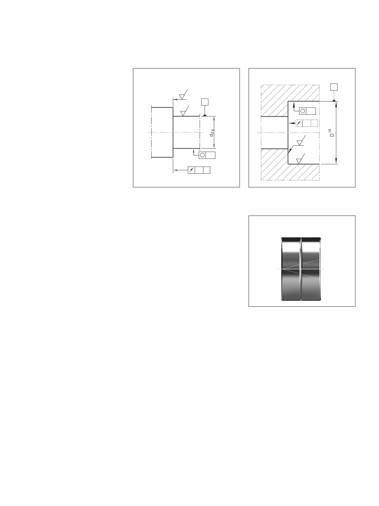
Bearing design
Screw end
Housing
For customer machining, please consider
the design notes for screw ends and
C
0,8
housings.
For Rexroth screw end designs, see
A
“End Machining Details.”
0,8
IT4
Rexroth delivers complete drive systems
including bearing units without housing.
IT5
C
Calculations are performed with the
formulas used in the antifriction bearing
1,6
industry.
IT3
1,6
IT4
A
Mounting
Angular-contact thrust ball bearings and deep-groove ball bearings
Outer raceway markings for paired
When mounting the angular-contact thrust ball bearings LGF and LGN, ensure that the
bearings
mounting forces are exerted only on the bearing rings. Never apply mounting forces via the
anti-friction bearing elements or the seal rings! The two sections of the inner raceway may
not be separated during assembly or disassembly for any reason!
Tighten the mounting screws for screw-down or flange-mounted bearings in crosswise
sequence. The mounting screws may be subjected only to tension amounting to a maximum
of 70% of their yielding point.
The screw-down (LGF) bearings have a groove on the cylindrical surface of the outer
raceway for disassembly. The individual bearings of the bearing pair series LGF-C... and
LGN-C... are marked on the cylindrical surfaces of the outer raceways (see Figure). The
markings reveal the bearing sequence. The sealing rings should face outwards after proper
mounting.
Slotted nut NMA, NMZ
The bearings are preloaded by tightening the nuts.
In order to prevent settling phenomena, we recommend first tightening the slotted nut by twice the value of the tightening torque MA and
then easing the load. Only then should the slotted nut be retightened to the specified tightening torque MA.
The two set screws are then alternately tightened using a hexagon socket wrench.
The components are disassembled in the reverse order, i.e. the set screws have to be removed before the slotted nut.
The slotted nuts can be used several times when properly assembled and disassembled by competent personnel. The inner raceways of
the bearings are dimensioned in such a way as to achieve a defined bearing preload sufficient for most applications when the slotted nut is
tightened (MA in accordance with Dimension Table).
187
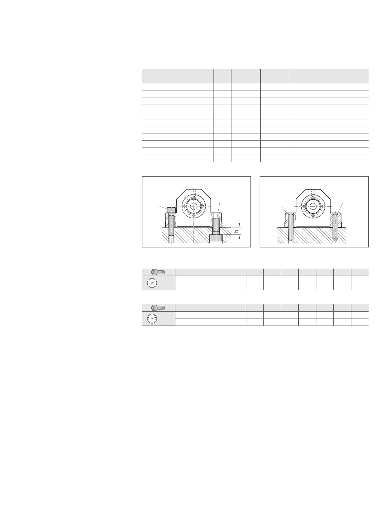
End Bearings
Mounting the housing
Size
h
O1
O2
O3, tapered pin (hardened)
Housing mounting SEB
d0xP
(mm)
DIN 912
DIN 912
O4, straight pin (DIN 6325)
Tighten the fastening screws of the pillow-
6x1/2
8
M5x20
M6x16
4x20
block bearings in a crosswise sequence.
8x1/2/2,5/5
8
M5x20
M6x16
4x20
Refer to the table for the maximum tight-
12x2/5/10
8
M5x20
M6x16
4x20
ening torque. The threaded ring fixes the
16x5/10/16
11
M8x35
M10x25
8x40
complete bearing in the housing. Use
20x5/10/20/40
11
M8x35
M10x25
8x40
threadlocking adhesive when assembling
25x5/10/25
14
M10x40
M12x30
10x50
the threaded ring.
32x5/10/20/32/64
14
M10x40
M12x30
10x50
40x5/10/12/16/20/25/30/40
16
M12x50
M14x35
10x50
50x5/10/12/16/20/25/30/40
16
M12x55
M14x35
10x60
cc
Align the screw with nut, the bear-
63x10/20/40
16
M12x65
M14x35
10x70
ings and the guide such that they are
80x10/20
22
M16x70
M20x50
12x80
completely flush with one another. The
Rexroth gauge is suitable as an aid.
Tightening
Locating pins
O2
O4
O1
O3
Steel/steel material pairing
Tightening torques for fastening screws
Strength class for O1; O2
M5
M6
M8
M10
M12
M14
M20
according to VDI 2230
8.8
5.5
9.5
23
46
80
125
390
where mG = mK = 0.125 (friction coefficient)
(Nm)
12.9
9.5
16.0
39
77
135
215
650
Steel/aluminum and aluminum/ aluminum material pairings
Strength class for O1; O2
M5
M6
M8
M10
M12
M14
M20
8.8
4.8
8.5
20
41
70
110
345
(Nm)
12.9
4.8
8.5
20
41
70
110
345
Mounting screws
cc
Always make sure the screws
are secure where there are high screw
loads!
188
Screw Assemblies | Ball Screw Assemblies BASA
End Bearings
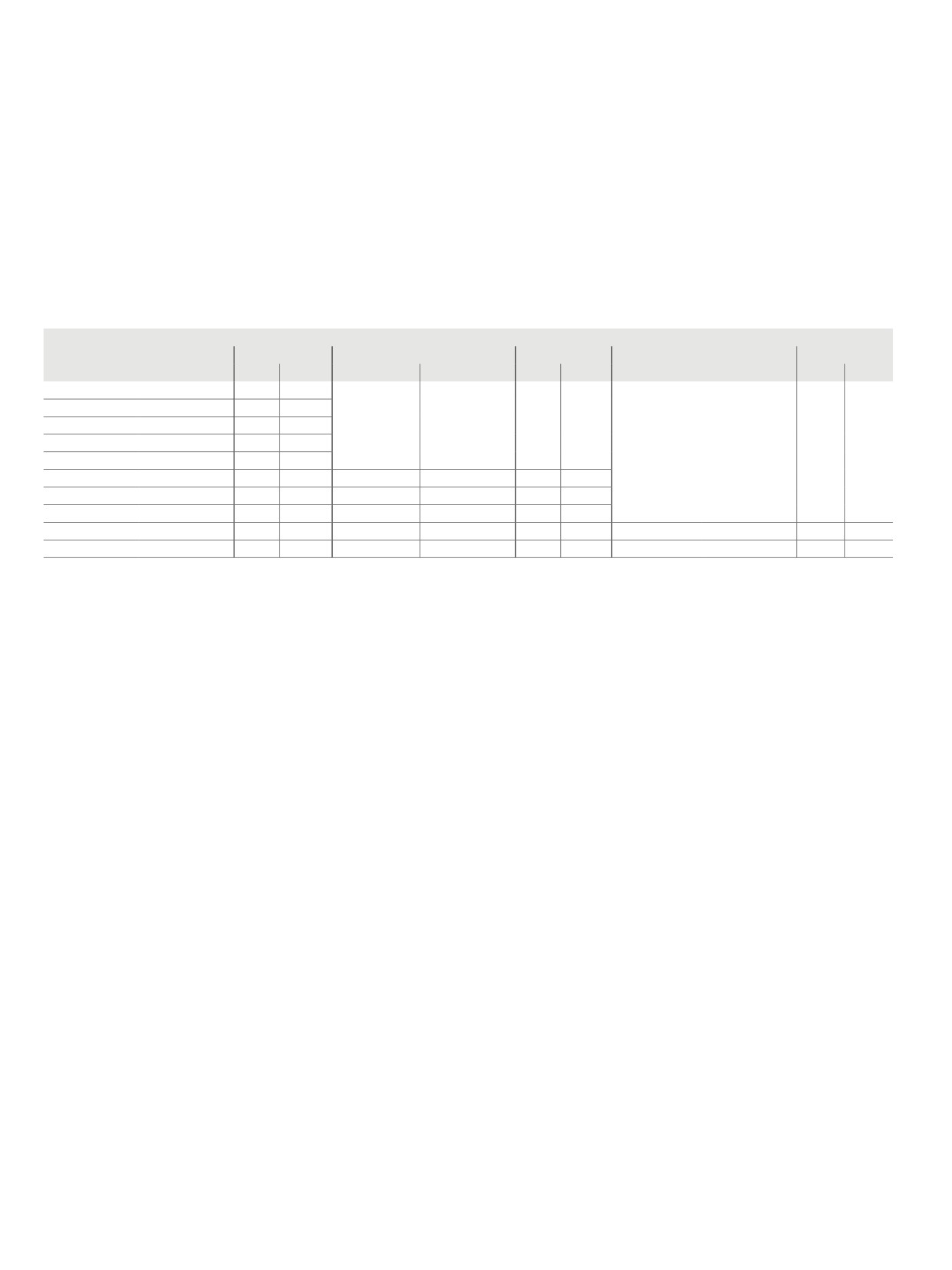
Lubrication of the end bearings
Bearings for Ball Screw Assemblies are lubricated with grease for a lifetime of reliable service. It should be noted, however, that grease
lubrication does not facilitate the dissipation of heat in the bearings. The bearing temperature should therefore not exceed 50 °C, particularly
in machine tool applications. At higher temperatures circulating oil lubrication must be set up. Angular-contact thrust ball bearings of series
LGF, LGN are lifetime-lubricated with KE2P-35 grease as per DIN 51825. For regreasing, the quantities stated in the table below can be
applied via the lube ports provided on the bearings. Where there are pairs of bearings, please note that each bearing must be individually
lubricated via the lube port. Each bearing must be lubricated with half the value shown in the table.The maximum interval can be assumed to
be 350 million revolutions, in which case the larger of the two quantities should be used. As a rule, the initial grease quantity will therefore
last for the entire service life of a Ball Screw Assembly.
Relubrication quantities for angular-contact thrust ball bearings
Abbreviation
Quantity (cm3)
Abbreviation
Quantity (cm3)
Abbreviation
Quantity (cm3)
1)
2)
1)
1)
LGN-B-0624
0.33
0.22
LGN-B-1034
0.33
0.22
LGN-B-1242
LGF-B-1255
0.43
0.33
LGN-B-1747
LGF-B-1762
0.54
0.43
LGN-B-2052
LGF-B-2068
0.87
0.54
LGN-B-2557
LGF-B-2575
1.09
0.65
LGN-C-2557
LGF-C-2575
2.17
1.3
LGN-B-3062
LGF-B-3080
1.09
0.65
LGN-C-3062
LGF-C-3080
2.17
1.3
LGN-B-3572
LGF-B-3590
1.74
0.98
LGN-A-4075
2.17
1.30
LGN-A-4090
LGF-B-40115
6.52
3.80
LGN-A-5090
2.72
1.63
LGN-A-50110
LGF-A-50140
9.78
5.98
1) Shortened lubricating interval max. 10 M revolutions
2) Where there are pairs of bearings, lubricate each bearing via the lube port.
Lubricate each bearing with half the value shown in the table.
189
End Bearings
Calculation
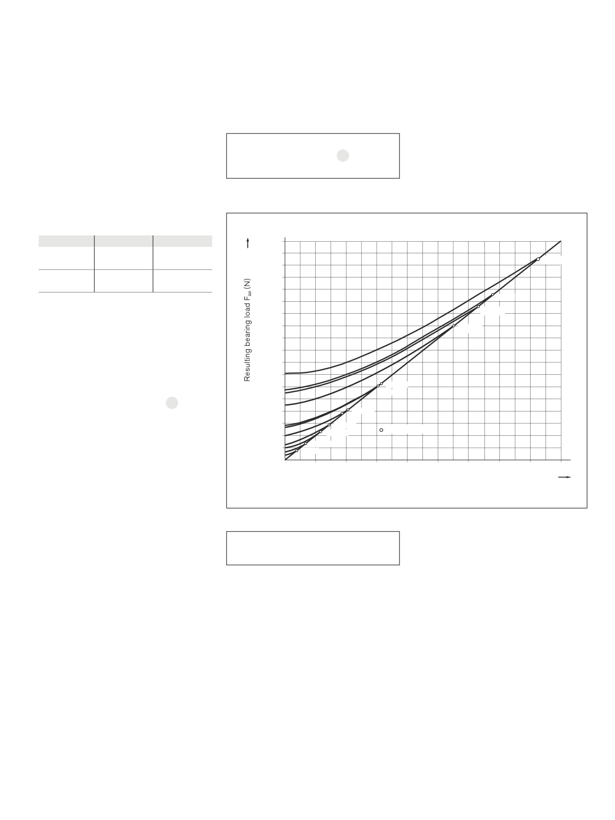
Resulting and equivalent bearing
loads
For angular-contact thrust ball bearings
Fax
= resulting axial bearing load
(N)
LGN and LGF
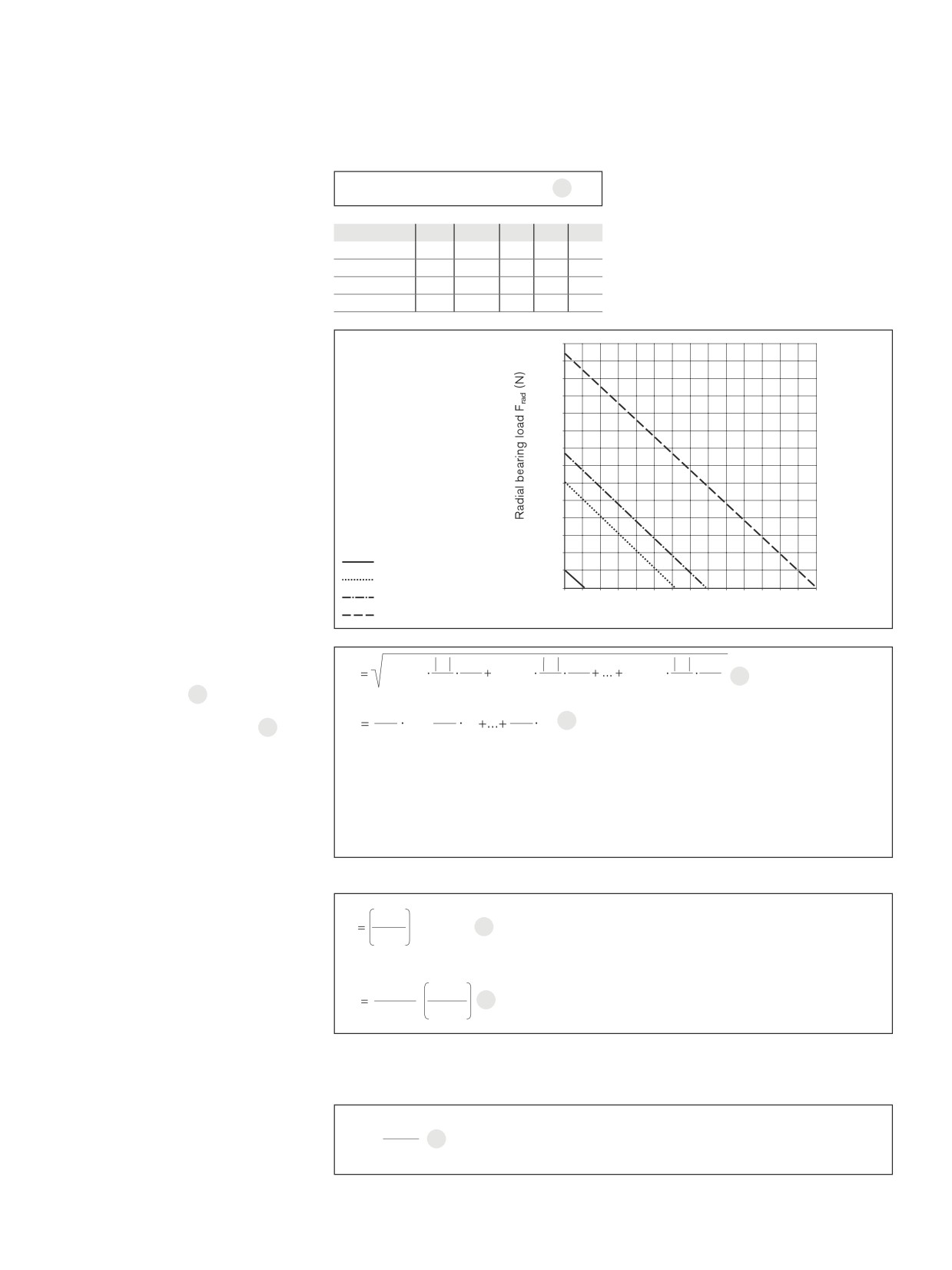
Fcomb = X · Frad + Y · Fax
20
Fcomb = combined equivalent load
(N)
Angular-contact thrust ball bearings are
Frad
= radial bearing load
(N)
preloaded. The chart shows the result-
ing axial bearing load Fax as a function of
preload and axial operating load FLax.
For a purely axial load Fcomb = Fax.
Internal preload limit and resulting bearing load
α = 60°
X
Y
18000
Fax
1.90
0.55
17000
≤ 2.17
d=50
Frad
16000
Fax
0.92
1.00
15000
> 2.17
Frad
14000
d=40
13000
α
= pressure angle
12000
d=301)
Fax
= resulting bearing load
11000
1)
d=25
FLax
= operating load
10000
X, Y
= dimensionless factor
9000
8000
7000
If the radial operating forces are not insig-
6000
d = 35
nificant, the equivalent bearing loads are
d = 30
5000
calculated according to formula 20.
4000
d = 20
Bearings for Ball Screw Assemblies are also
suitable to accommodate tipping forces.
3000
d = 17
Limit values
2000
d = 12
The moments that usually occur due to the
d = 10
mass and drive motion of the screw do not
1000
d = 6
generally need to be included in the calcula-
2000
4000
6000
8000
10000
12000
14000
16000
18000
tion of the equivalent bearing load.
Operating load FLax (N)
1) Four row version
Permissible static axial load for
C0
F0ax p = permissible static
F0ax p ≤
bearing series LGF
2
axial bearing load
(N)
The permissible static axial load of LGF
series bearings in screw-down direction is:
The static axial load rating C0 is stated in the Dimension Tables.
cc
Separate technical dimensioning to determine the limit values is absolutely necessary for all attachments (e.g. pillow block
units, bearing assembly, etc.)
190
Screw Assemblies | Ball Screw Assemblies BASA
End Bearings
Calculation
Resulting and equivalent bearing
Fcomb = X · FradA + Y · FaxB + Z
21
Fax
= axial bearing load
(N)
loads
Fcomb
= combined equivalent load
(N)
Frad
= radial bearing load
(N)
Bearing size
X
Y
Z
A
B
For angular-contact thrust ball bearings LGL
X, Y, Z = calculation factors
(-)
LGL-D-0624
0.003
0.1300
140
1.90
1.40
Before determining the combined equivalent
A, B
= exponents
(-)
LGL-A-1244
0.076
0.0460
580
1.28
1.30
load, Fcomb, you must check the bearing size
LGL-A-1547
0.022
0.0110
540
1.45
1.50
for the static limit load using the diagram. In
LGL-A-2060
0.017
0.0082
960
1.45
1.50
this connection, the intersection point of the
axial and radial bearing load must be below the
muss boundary for a bearing to be suitable for
Static limit load
7000
the application.
6500
6000
5500
5000
4500
4000
3500
3000
2500
2000
1500
1000
LGL-D-0624
500
LGL-A-1244
0
LGL-A-1547
0
400
800
1200
1600
2000
2400
2800
LGL-A-2060
Axial bearing load Fax (N)
Average speed and average bearing load
3
n1
qt1
n2
qt2
qtn
nn
When the bearing load varies in steps over
Fm
Fcomb13
Fcomb23
Fcombn3
22
n
m
100
nm
100
nm
100
a specific period of time 22, calculate the
dynamic equivalent bearing.
q1
q2
qn
n
n1+
n2
nn
23
When the speed varies, use formula 23. In
m
100
100
100
these formulas qt
denotes the discrete time
Fcomb1 ... Fcombn = combined equivalent axial load in phases 1 ... n
(N)
steps for the individual phases in %.
Fm
= dynamic equivalent bearing load
(N)
n1 ... nn
= speeds in phases 1 ... n
(rpm)
nm
= average speed
(rpm)
qt1 ... qtn
= discrete time steps in phases 1 ... n
(%)
Service life and load safety factor
3
C
C
= dynamic bearing load rating
(N)
L
· 106
24
Fm
Fm
= combined equivalent load on bearing
(N)
L
= nominal service life in revolutions
(-)
Nominal service life
Lh
= nominal service life in operating hours
(h)
The nominal service life is calculated as
3
nm
= average speed
(rpm)
follows:
16 666
C
L
·
25
h
nm
Fm
Attention:
Pay attention to the dynamic load rating
of the nut!
Static load safety factor
F0max = maximum static load
(N)
C0
The static load safety factor for machine
S
0 =
26
C0
= static load capacity
(N)
F0max
tools should not be lower than 4.
S0
= static load safety factor
(-)
191
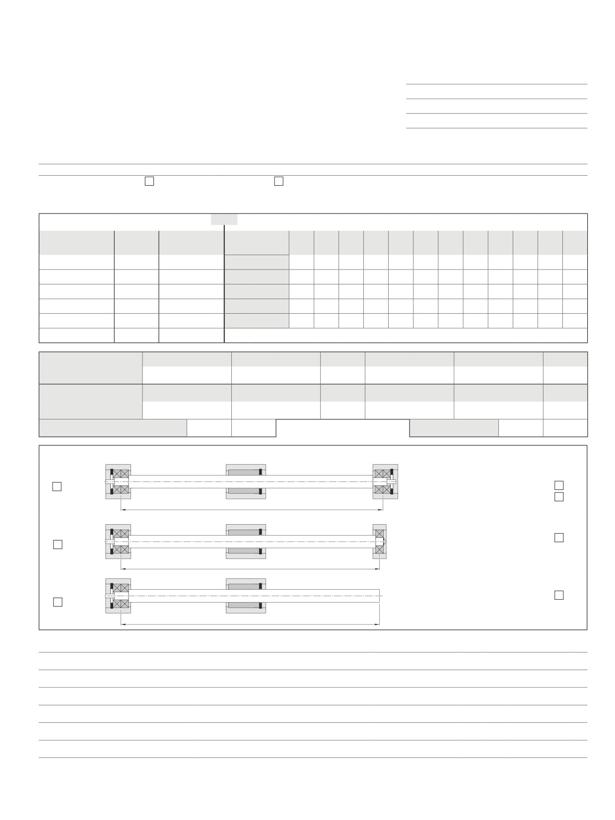
Design Calculation Service Form
Bosch Rexroth
Company:
Linear Motion Technology
Contact:
E-mail:
97419 Schweinfurt / Germany
Telephone:
Find your local contact person here: www.boschrexroth.com/adressen
Application
New design
Revised design
Operating conditions
Discrete time step parameters
or
Dynamic cycle parameters
Discrete time steps
Speed
Action of force x
Section
T1
T2
T3
T4
T5
T6
T7
T8
T9
T10
T11
T12
(%)
(1/min)
T1 =
n1 =
Path
(mm)
T2 =
n2 =
V
(m/s)
T3 =
n3 =
a
(m/s2)
T4 =
n4 =
Time
(s)
T5 =
n5 =
Action of force x
T6 =
n6 =
F1
F2
F3
F4
F5
F6
Forces
(N) =
m1
m2
m3
m4
m5
m6
Mass
(kg) =
Bearing center-to-center distance
(mm) =
or
Max. stroke
(mm) =
Bearing type
Installation Position
1.
Tight
Tight
Horizontal
Vertikal
Ls
Drawing enclosed
2.
Tight
Loose
(recommended)
Ls
Delivery with bearing
3.
Tight
Free
Ls
Required life:
Operating temperature:
°C Up to
°C
Type of lubrication:
Short description of the application / unusual operating conditions:
Visit out official homepage and use the provided configurators and our dimensioning program Linear Motion Designer free of charge.
192
Screw Assemblies | Ball Screw Assemblies BASA
Planetary Screw Assemblies PLSA | Screw Assemblies
193
Planetary Screw Assemblies PLSA
194
Screw Assemblies | Planetary Screw Assemblies PLSA
New features at a glance
New features at a glance
The divided FDM-E-S of the Single Nut with flange nut type has been discontinued.
cc
FDM-E-S
New screw sizes 25x5 and 25x10
To add to our product portfolio, the intermediate sizes 25 with leads 5 and 10 have been
issued.
This size is available for the nut types Cylindrical Single Nut ZEM-E-S and Single Nut with
flange FEM-E-S.
Cover plate wiper
To expand on our seal system, the cover plate wiper has been issued.
This is suitable especially for applications in the temperature range of 60° and higher.
cc
Cover plate wiper
without friction torque,
Expansion of the documentation
TRD = 0 Nm
Option 5 = Two-point compensation
This kind of documentation is intended to compensate for the lead error of a screw.
Planetary Screw Assemblies PLSA | Screw Assemblies
195
Table of contents
Table of contents Planetary screw assemblies
New features at a glance
194
Installation
260
Installation Tolerances
262
Table of contents
195
Lubrication
263
Product overview
196
Nuts, Screws, Screw Ends, Bearings
196
Calculation
266
Planetary Screw Assembly - Definition
197
End Bearings
272
Sample applications
198
End Bearings
272
Lubrication of the end bearings
273
Inquiries and orders
200
Design Calculation Service Form
276
Overview of formats/abbreviations
202
Further information
277
Nuts
202
Cylindrical single nut ZEM-E-S
202
Single nut with flange FEM-E-S
204
Screws
206
Precision screw PSR
206
Screw ends
208
Abbreviations
209
Form 002
209
Form 112, 122
210
Form 132, 142
212
Form 212, 222
214
Form 312
216
Form 412
218
Form 512, 522
220
Form 532, 542
222
Form 612, 622
224
Form 812, 822
228
Form 832, 842
230
Accessories
236
Overview
236
Bearing assembly LAF
238
Bearing assembly LAN
240
Bearing assembly LAD
242
Bearing assembly LAS
244
Bearing assembly FEC-F
246
Slotted nuts NMA for fixed bearings
248
Ring nut GWR
249
Measuring pads
250
Technical data
252
Technical notes
252
Acceptance Conditions and Tolerance Grades
255
Preload, Rigidity, Friction Torques
258