HNC8 Series CNC Controller. Programming Manual (V2.4) - page 9
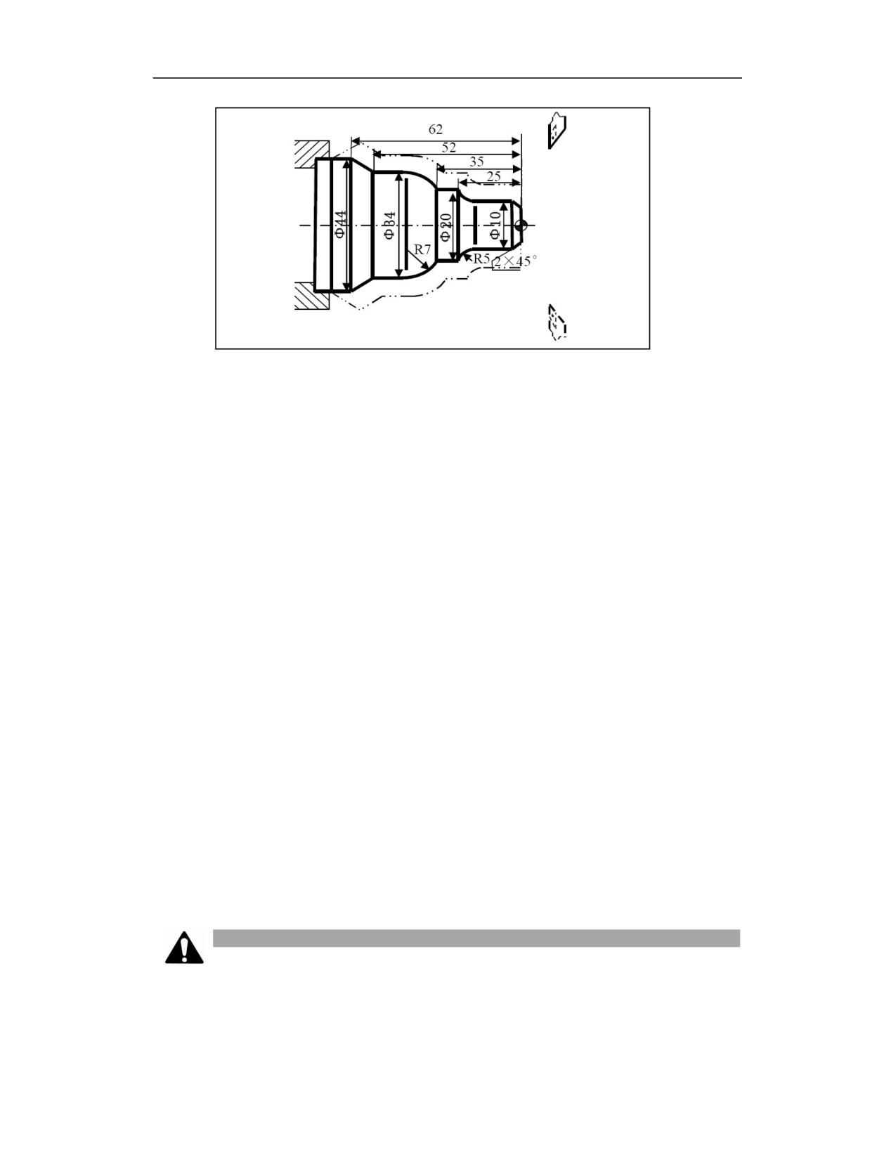
%0330
N1 T0101; Set coordinate system, select No.1 tool
N2 G00 X80 Z80; Move to starting point of program
N3 M03 S400; Spindle rotates CW at 400r/min
N4 G00 X60 Z5; Move to starting point of cycle
N5 G73U3W0.9R3P6Q13X0.6Z0.1F120; Closed roughing cycle
N6 G00 X0 Z3; Contour finishing starts, move to extension line of chamfer
N7 G01 U10 Z-2 F80;
2×45°chamfer finishing
N8 Z-20; Φ10 outer circle finishing
N9 G02 U10 W-5 R5; R5 arc finishing
N10 G01 Z-35; Φ20 outer circle finishing
N11 G03 U14 W-7 R7; R7 arc finishing
N12 G01 Z-52; Φ34 outer circle finishing
N13 U10 W-10; Cone finishing
N14 U10; Exit machined surface, contour finishing end
N15 G00 X80 Z80; Return to starting point of program
N16 M30; Spindle stop, main program end and reset
Note
(1) The rough turning cycle is realized by the G73 command with addresses P and Q. The F, S
and T functions specified in the motion command are invalid. But the F, S and T functions
specified in the G72 block or the previous block are valid.
320

(2) When the constant speed limit is used for cutting speed control, the G96 or G97 specified in
the movement command between "ns" and "nf" is invalid. It is valid to specify G96 or G97 in the
G73 block or the previous block. The blocks between the sequence numbers na and nf cannot call
subprogram.
(3) G72 cannot be the same line with M code.
(4) In the any line with scanning mode, the blocks between ns and nf cannot be specified.
(5) The number of divisions R can only be given as an integer value. If the specified value is a
decimal, it will be rounded up.
17.4
Thread Cutting Multiple Repetitive Cycle (G76)
Function and Purpose
Threading is a forming processing, and the cutting amount per cut cannot be too large, so
processing a threaded part often requires multiple processing to complete.
This command can use a cycle command to realize multiple reciprocating motions and finally
complete the processing of threaded parts. It includes multiple roughing and at least one finishing.
Command Format
G76 C(c) R(r) E(e) A(a) X(x) Z(z) I(i) K(k) U(d) V(dmin) Q(d) P(p) F
Parameter
Meaning
C
Number of finishing (c=1 to 99), modal value
R
Undercut length on Z (The positive or negative R value determines the direction
of undercut on Z axis), modal value
E
Undercut length on X (The positive or negative E value determines the direction
of undercut on X axis), modal value
A
Tool nose angle (A value is a two-digit integer), modal value; the value is larger
than 10° and smaller than 80°
X Z
Coordinate of the effective thread end point C in absolute programming;
directional distance from the end point C of thread to starting point A of cycle
in incremental programming
I
Radius difference between the starting point and the end point of thread cutting
(The positive or negative I value determines the direction of taper); I=0 for
straight thread, and I is negative for normal tapered thread
K
Thread cutting height (K is the radius, and is generally the thread tooth height)
U
Finishing allowance (d is the radius)
321
V
Min. cutting depth
(dmin is the radius); when the nth cutting depth
d
nd
n 1 is smaller than dmin, the cutting depth is set to dmin
Q
The first cutting depth (d is the radius)
P
Spindle rotation angle from the spindle reference pulse to the cutting start point
F
Thread lead (same as G32), F is in metric
Description
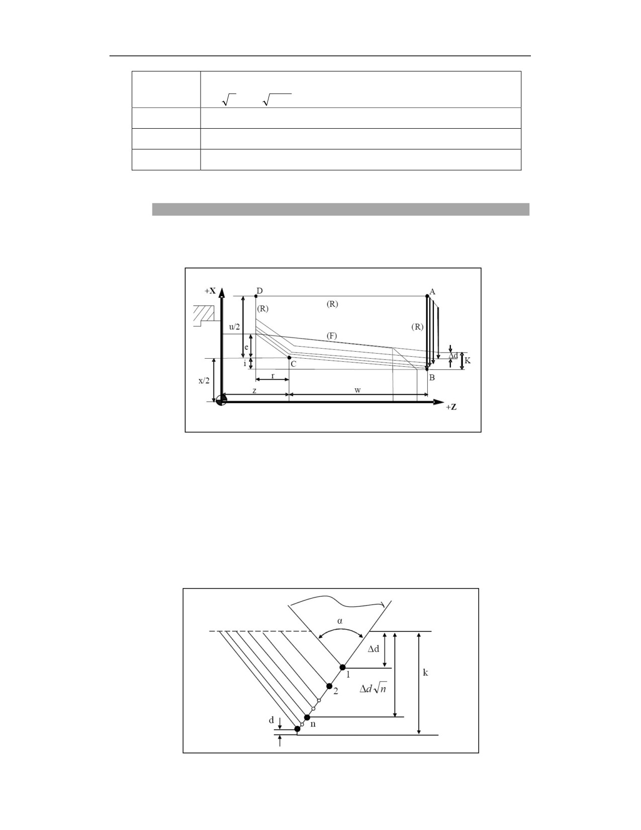
For machining path of G76 thread multiple repetitive cycle, see the figure below,
There are 4 paths for each reciprocation,
1st path A→B, R rapid traverse feed
2nd path B→C, F speed thread feed
3rd path C→D, R rapid traverse feed (including E, R undercut path)
4th path D→A, R rapid traverse feed
Cutting depth setting for thread multiple repetitive cycle, see the figure below,
322
Example
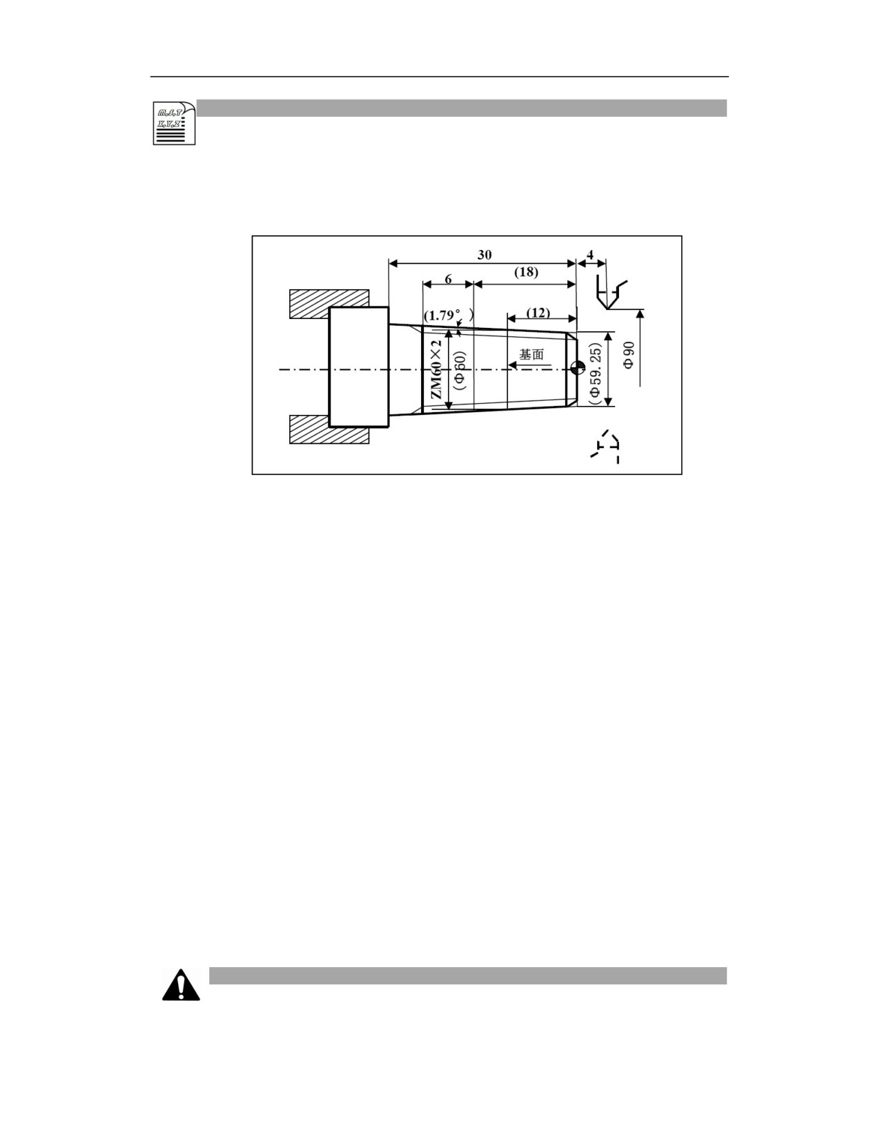
Example 1: Use the thread cutting multiple repetitive cycle G76 for programming. The thread to
be processed is ZM60×2, the workpiece size is shown in the figure below, and the size in brackets
is obtained according to the standard. (Tan1.79=0.03125).
%3331
N1 T0101; Select No. 1 tool, and determine the coordinate system
N2 G00 X100 Z100; Move to the starting point of program or tool change position
N3 M03 S400; Spindle rotates CW at 400r/min
N4 G00 X90 Z4; Move to the starting point of simple cycle
N5 G80 X61.125 Z-30 I-1.063 F80; Machine the outer surface of tapered thread
N6 G00 X100 Z100 M05; Move to the starting point of program or tool change
position
N7 T0202; Change to No. 2 tool, and determine the coordinate system
N8 M03 S300; Spindle rotates at 300r/min
N9 G00 X90 Z4; Move to the starting point of thread
N10 G76C2R-3E1.3A60X58.15Z-24I-0.875K1.299U0.1V0.1Q0.45F2
N11 G00 X100 Z100; Return to the end point of program or tool change position
N12 M05; Spindle stop
N13 M30; Main program end and reset
Note
(1) The cycle processing is realized based on the X(x) and Z(z) commands in the G76 block. In
323
incremental programming, note the sign of u and w (determined by the direction of the tool path
AC and CD);
(2) G76 is used to perform the single-side cutting, which reduces the force on the tool tip. The
cutting depth for the first cut is
d, the total cutting depth for the nth cut is
d
n, and the
(
n
n
1
)
amount of cutting depth in each cycle is d
;
(3) In the single-side cutting diagram, the cutting speed from point B to C is specified by the
thread cutting speed, and other paths are the rapid traverse feed.
(4) During thread cutting, the feed hold and reset bottons are invalid;
(5) During thread cutting, feed override is invalid;
(6) To avoid tool interference, the starting point of the thread cutting cycle should be set above
the apex of the thread pitch;
(7) When the tapered thread cutting is executed, the thread pitch is calculated in the way of axis,
and the actual processing speed is calculated in the way of generatrix.
18 Programming Simplifying Function (M)
18.1
Mirroring Function(G24,G25)
Function and Purpose
When editing a symmetrical shape processing program, user only needs to program any one side
of the shape for the processing of the other side of the shape, which can save the time required
for programming. At this time, the most effective function is the mirroring function.
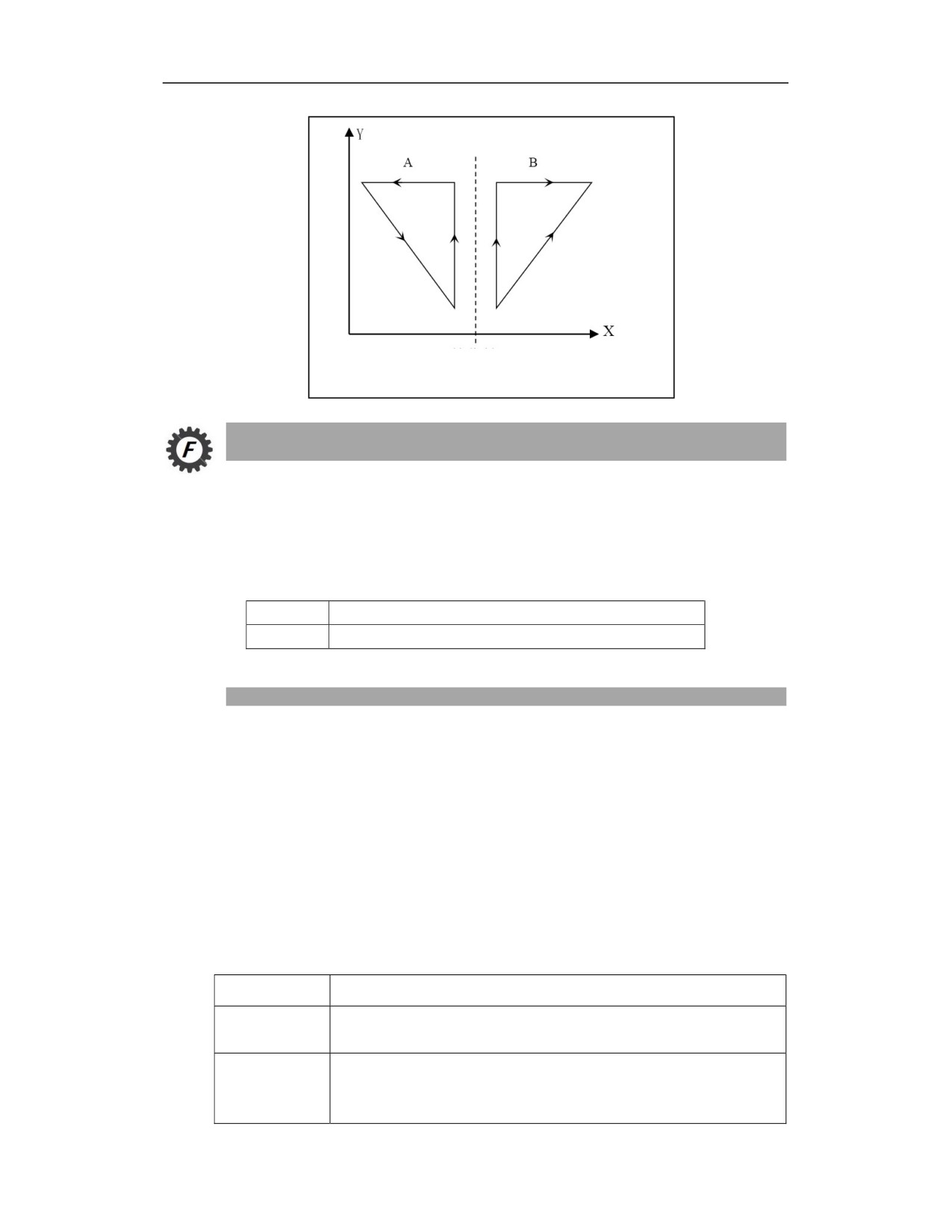
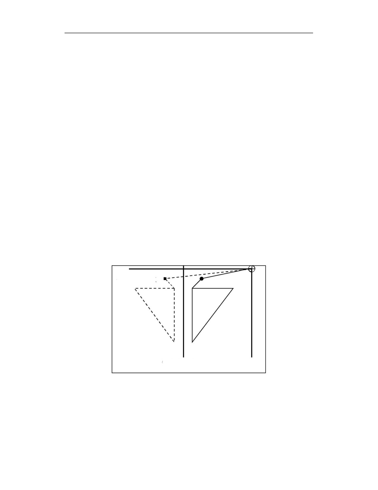
For example, as shown in the figure below, when there is a program for processing the shape A
on the left, the shape B that is symmetrical to the A can be completed on the right by mirroring
the program.
324
Mirroring axis
Command Format
G24 IP_; Establish mirroring
…… Tool path programming commands
G25 IP0; Cancel mirroring
Parameter
Meaning
IP
Mirroring axis position
Description
(1) In G24, the mirroring axis and mirroring enter coordinates are specified in absolute or
incremental programming.
(2) In G24, user can specify axisymmetric mirroring and point-symmetric mirroring.
a) Axisymmetric mirroring
b)
(G17/G18/G19) G24 α_/β_;
c)
…… ;
d) G25;
Parameter
Meaning
Plane selection for mirroring, this plane should include programmed tool
G17/G18/G19:
path
Symmetry axis of mirroring. Only one of α_ and β_ can be specified. α
G24 α_/β_:
represents the first axis of the selected plane, and β represents the second
axis of the selected plane. If an axis on a non-selected plane is specified, the
325
system alarms.
……:
Programmed tool path commands
Cancel mirroring. When running the program, only write G25, or α and β
G25α0/β0:
after G25 are specified as any values, the mirroring function can be
cancelled.
Point symmetry mirroring
(G17/G18/G19) G24 α_ β_;
…… ;
G25;
Parameter
Meaning
Plane selection for mirroring, this plane should include the programmed tool
G17/G18/G19:
path
Symmetry axis of mirroring. When α_ or β_ is omitted, the current tool
G24 α_β_:
position is defaulted. If an axis on a non-selected plane is specified, the
system alarms.
……:
Programmed tool path commands
Cancel mirroring. When running the program, only write G25, or α and β after
G25 α0 β0:
G25 are specified as any values, the mirroring function can be cancelled.
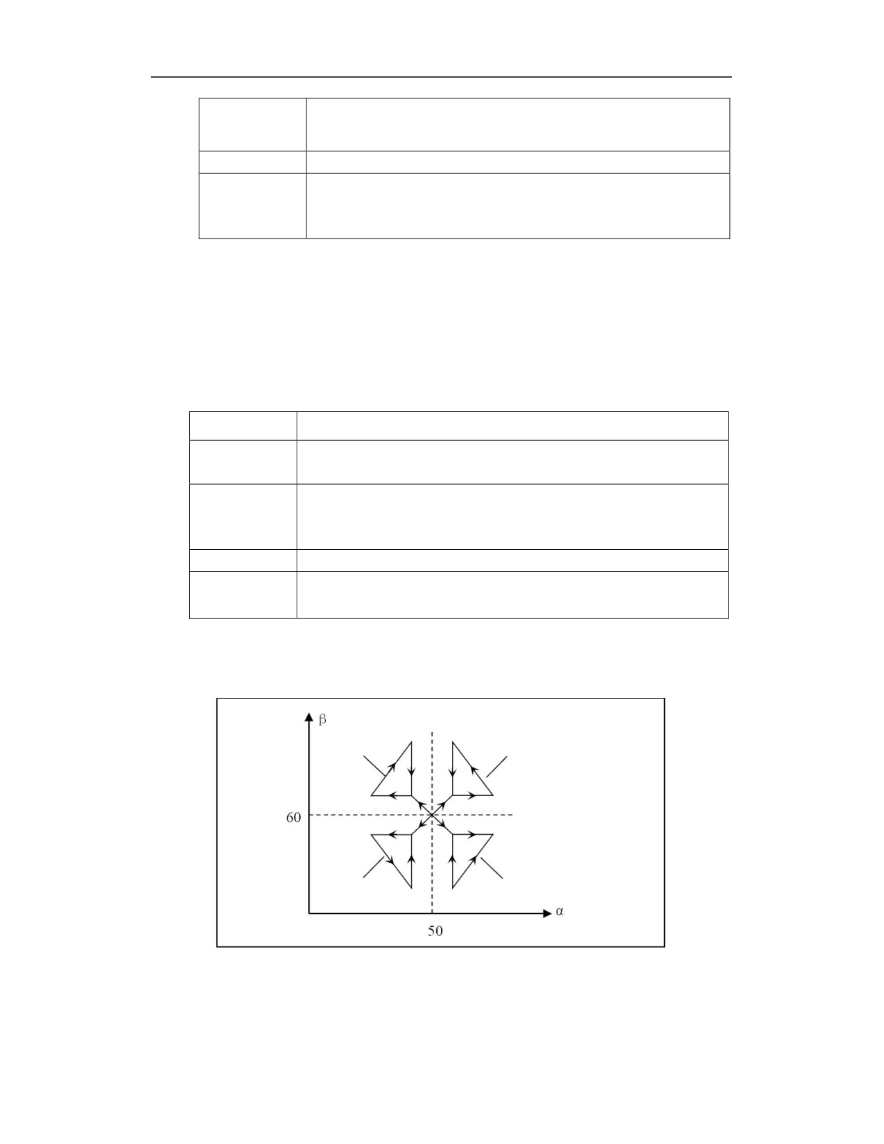
The diagram of axisymmetric and point-symmetric mirroring is as follows:
Mirroring path 1
Programmed path
Mirroring path 2
Mirroring path 3
A mirror image path 1 and the programmed path are axisymmetrical, the axis of
symmetry is α=50;
B mirror image path 2 and the programmed path are point-symmetrical, and the
326
symmetrical point is (50, 60);
C mirror image path 3 and the programmed path are axisymmetric, and the
symmetry axis is β=60;
(3) By specifying G24 α_, the β-axis symmetry mirror can be established.
(4) When the β-axis mirror image is established, specify G25 α0 to cancel the β-axis mirror image.
For example, when G24 X0 Y0 is specified to establish the point-symmetric mirroring, user can
cancel the Y-axis symmetrical mirroring and only specify the X-axis symmetrical mirroring by
specifying G25 X0.
(5) When only mirroring is specified on the first axis of the specified plane, the rotation direction
and compensation direction in arc, tool radius compensation, and coordinate rotation are all
reversed.
(6) The mirror image center of the local coordinate system will move due to the preset coordinate
system and the change of the workpiece coordinate.
(7) G24 block and G25 block must be specified seperately.
(8) G24 is a modal command, can be canceled by G25 after mirroring function is finished.
(9) When no axis follows G25, all mirroring is canceled.
(10) When the reference point return command (G28, G30) is executed in mirror image, the mirror
image is valid in the motion before the intermediate point is reached, so the mirror image is not
executed in the motion from the intermediate point to the reference point.
Mirrored
intermediate point
Intermediate point
Mirroring path
Programmed path
Mirroring axis
(11) When the return from origin command (G29) is specified in the mirroring, the mirroring is
performed to the intermediate point.
(12) The mirror image is not executed to G53.
(13) The mirror image is processed after the tool radius compensation (G41, G42) is executed, so
the cutting path as shown in the figure below is performed.
327
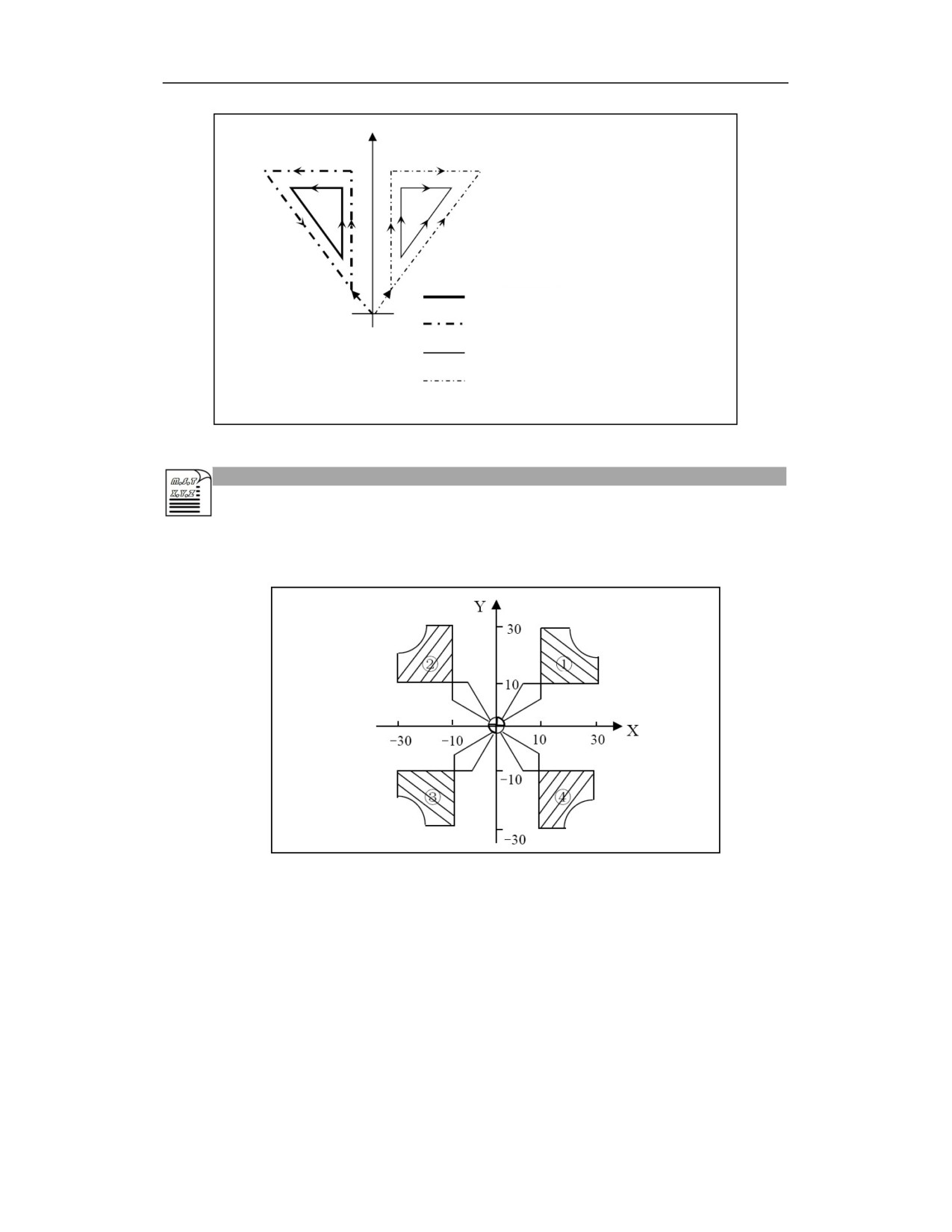
Programmed path
Path when only the tool compensation is executed
Path when only the mirroring is executed
Path when both mirroring and tool compensation
are executed
Example
Use the mirror image function to program the contour as shown in the figure: set the starting point
of the tool to be 100mm from the upper surface of the workpiece, and the depth of cut is 5mm.
%3331
;Main program
G92 X0 Y0 Z100
G91 G17 M03 S600
M98 P100
;Machining ①
G24 X0
;Y-axis mirror image, the mirroring position is X=0
M98 P100
;Machining ②
G24 Y0
;X, Y axis mirror image, the mirroring position is (0, 0)
M98 P100
;Machining ③
G25 X0
;X-axis mirroring continues to be effective, cancel Y-axis mirroring
M98 P100
;Machining ④
G25 X0 Y0
;Cancel mirroring
328
M30
%100
;Subprogram (processing program of figure ①)
N100 G41 G00 X10 Y4 D01
N120 G43 Z10 H01
N130 G01 G90 Z-3 F300
N140 G91 Y26
N150 X10
N160 G03 X10 Y-10 I10 J0
N170 G01 Y-10
N180 X-25
N185 G00 Z10
N190 G90 G49 G00 Z100
N200 G40 X0 Y0
N210 M99
329

18.2
Scaling Function(G50,G51)
Function and Purpose
When executing the scaling function, the programmed path is enlarged or reduced based on the
given scaling factor.
Command Format
G51 IP_ P_ ; Scaling starts
……
G50
; Cancel scaling
Parameter
Meaning
IP
Specify the coordinates of the scaling center point. If it is not specified,
specify the current point as the scaling center point.
This command always specifies the absolute position of the scaling
center in the workpiece coordinate system.
P
Specify the scaling factor of each axis.
All axes are scaled by this factor.
Description
(1) Designation of scaling axis, scaling center and magnification
After issuing the G51 command, the scaling mode is entered. The G51 command only specifies
the scaling axis, scaling center and magnification and doesn’t specify the movement.
Although executing the G51 command will enter the scaling mode, in fact the effective axis for
scaling is only the axis for which the scaling center is set.
(a) Scaling center
The center of the scaling is specified based on the absolute/incremental mode (G90/G91). In the
G51 block, whether it is in incremental or absolute mode, the center of the scaling refers to the
absolute position in the workpiece coordinate system.
Even if the current position is the center, it must be specified.
The effective axis for scaling is limited to the axis for which the scaling center is specified.
(b) Scaling magnification
The scaling magnification is specified with the address P.
The magnification for scaling only can be specified after G51.
330
Scaling magnification ranges from 0.000001 to 99999999999
When the scaling magnification is not specified, 1 is specified by default.
(c) A program error will occur in the following situations.
The scaling magnification exceeds the upper limit of the magnification command range.
(2) Scaling is cancelled. After specifying G50, the scaling is cancelled.
Example
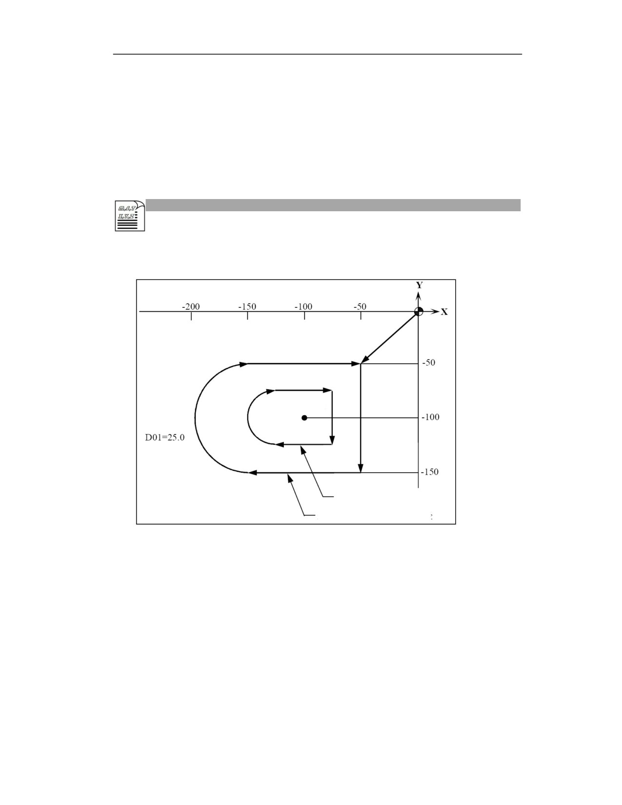
Example 1: Use the scaling function to create the program with 1/2 scaling and the program
without scaling in the figure below.
Scaling center
Programmed path after 1/2 scaling
Programmed path without scaling
%1234
G92 X0 Y0 Z0;
G90 G51 X-100. Y-100. P0.5;
G00 G43 Z-200. H02;
G41 X-50. Y-50. D01;
G01 Z-250. F1000;
Y-150. F200;
X-150.;
G02 Y-50. J50.;
G01 X-50.;
331
G00 G49 Z0;
G40 G50 X0 Y0;
G90 G51 X-100. Y-100. P1;
G00 G43 Z-200. H02;
G41 X-50. Y-50. D01;
G01 Z-250. F1000;
Y-150. F200;
X-150.;
G02 Y-50. J50.;
G01 X-50.;
G00 G49 Z0;
G40 G50 X0 Y0;
M30;
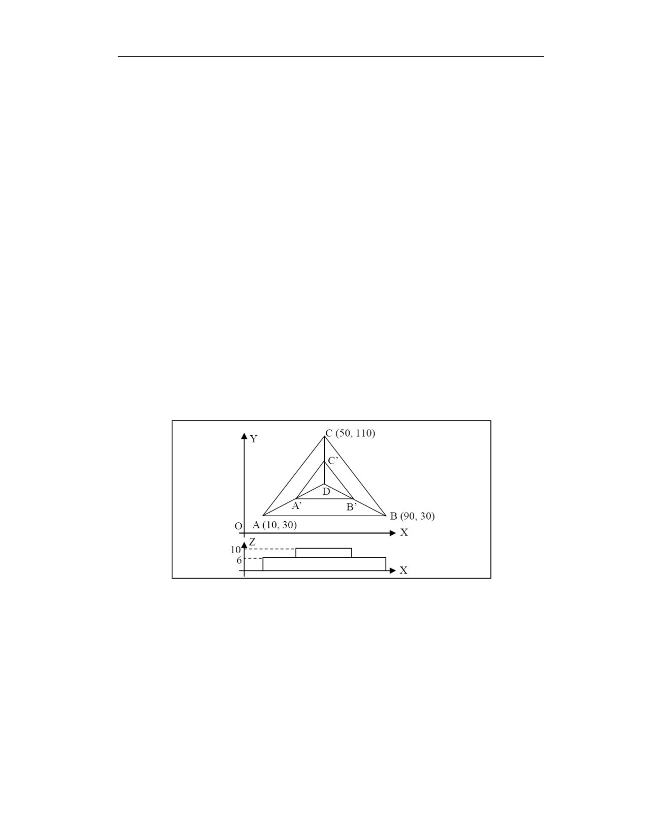
Example 2: Use the scaling function to create the program of the contour as shown in the figure
below: The vertices of the triangle ABC are A (10, 30), B (90, 30), C (50, 110), and the triangle
A'B'C 'is the zoomed one, where the scaling center is D (50, 50), the scaling factor is 0.5 times,
and the starting point of the tool is 50mm from the upper surface of the workpiece.
332
%3332
;Main program
G92 X0 Y0 Z60
G17 M03 S600 F300
G43 G00 Z14 H01
X110 Y0
#51=0
M98 P100
;Machine triangle ABC
#51=6
G51 X50 Y50 P0.5
;Scaling center (50,50), scaling factor 0.5
M98 P100
;Machine triangle A'B'C'
G50
;Cancel scaling
G49 Z60
G00 X0 Y0
M30
%100
;Subprogram (the processing programi of triangle ABC)
N100 G41 G00 Y30 D01
N120 Z[#51]
N150 G01 X10
N160 X50 Y110
N170 G91 X40 Y-80
N180 G90 Z[#51]
N200 G40 G00 X110 Y0
N210 M99
Note
(1) When there is tool compensation, perform scaling first, and then tool radius compensation and
tool length compensation. The scaling does not change the tool radius compensation value and
tool length compensation value.
(2) Scaling is only valid for traverse commands in auto mode. It is invalid for the traverse in JOG.
When the movement is in JOG mode, the breakpoint must be returned first.
(3) Scaling is valid to the axes of which X, Y, Z are specified, and invalid to the axes of which X,
Y, Z are not specified.
(4) The G51 block must be specified separately.
333

(5) If M02 or M03 command is specified in scaling mode, or NC reset is executed, the scaling is
canceled.
(6) When the coordinate system is offset (G92, G52 commands) or switched in the scaling mode,
then the scaling center will be offset based on the coordinate system offset amount.
(7) When G28, G30, or G29 command is secified in scaling mode, the scaling is not canceled.
(8) When the G51 command is issued in the scaling mode, the axis of the newly-specified center
becomes the effective scaling axis. The magnification is based on the newly specified G51.
(9) When G60 (unidirectional positioning) is issued in scaling mode, neither the final positioning
point nor the crawling amount is scaled.
(10) When the graphics rotation is specified in the scaling mode, the graphics rotation center and
the radius will be scaled.
(11) If the scaling command is issued in the graphics rotation subprogram, the radius of the
graphics rotation is not scaled, but only the shape determined by the subprogram is scaled.
18.3
Rotation Transformation(G68,G69)
Function and Purpose
The rotation transformation is used to rotate the programmed processing path around the rotation
center by a specified angle. If the shape of the workpiece is composed of many identical graphics,
the graphics unit can be compiled into a subprogram which is then called by the rotation
transformation command of the main program.
Command Format
G17/G18/G19; Select a rotation plane
G68 IP_ P_; Establish rotation transformation
……
G69;
Cancel rotation transformation
Parameter
Meaning
IP
To specify coordinates of the rotation center. If it is not specified, it is the
current point of the tool.
The absolute position in the workpiece coordinate system whether it is in
absolute or incremental mode
P
Rotation angle (unit: degree), counterclockwise rotation indicates a positive
value, clockwise rotation indicates a negative value
334
Description
(1) The coordinate of the rotation center are always specified as an absolute value. Even if it is
specified as an incremental address, it will not be treated as an incremental value. Regardless of
the rotation angle specified in G90 or G91, P is always the absolute value of the angle of the first
axis in positive direction in the specified reference plane.
(2) If the coordinate of the rotation center is omitted, the position where the G68 command is
located will become the rotation center.
(3) The value of rotation angle P ranges from
-360 to
360. The value is positive for
counterclockwise direction, and negative for clockwise direction. When the angle command
exceeds 360 degrees, the system will issue that the parameter is illegal.
(4) The rotation angle P is a modal value and will not change until a new angle is specified next
time. The rotation angle can be omitted. If the rotation angle is omitted when G68 is specified for
the first time, P will be regarded as 0. If the rotation angle is omitted when G68 is not specified
for the first time, P will inherit the previous rotation angle.
(5) Use G69 to cancel it after the rotation transformation is completed. If M02 or M30 is specified
in the coordinate rotation mode or the reset button is pressed, the coordinate rotation will be
cancelled.
(6) In coordinate rotation mode, G68 is not displayed on the modal information screen, and G69
is not displayed after the mode is cancelled.
(7) The coordinate rotation function is valid in both auto and single-block working modes.
Example
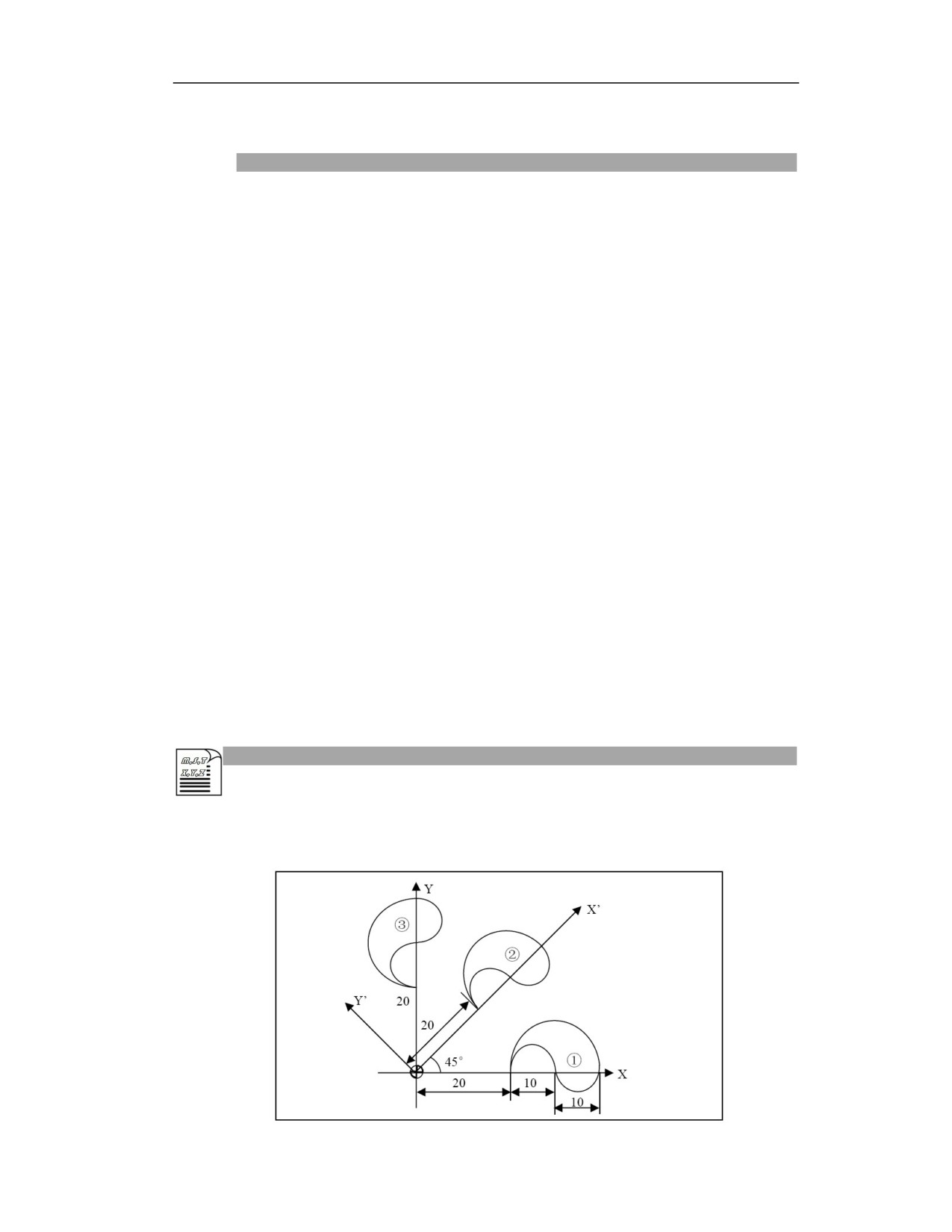
Use the rotation function to program the contour as shown in the figure: the starting point of the
tool is 50mm from the upper surface of the workpiece, and the depth of cut is 5mm.
335
%3333
;Main program
N10 G92 X0 Y0 Z50
N15 G90 G17 M03 S600
N20 G43 Z-5 H02
N25 M98 P200
;Machine ①
N30 G68 X0 Y0 P45
;Rotate 45°
N40 M98 P200
;Machine ②
N60 G68 X0 Y0 P90
;Rotate 90°
N70 M98 P200
;Machine ③
N20 G49 Z50
N80 G69 M05 M30
;Cancel rotation
%200
;Subprogram (Program of graphic
①)
G41 G01 X20 Y-5 D02 F300
N105 Y0
N110 G02 X40 I10
N120 X30 I-5
N130 G03 X20 I-5
N140 G00 Y-6
N145 G40 X0 Y0
N150 M99
Note
(1) The traverse command following G68 and G69 must be an absolute value command.
(2) In coordinate rotation mode, G codes related to the reference point (G28, G29, G30, etc.) and
commands used to change the coordinate system (G52, G54 to G59, G54X, G92, etc.) cannot be
specified. Otherwise, the coordinate rotation command needs to be cancelled first.
(3) G68 and G69 are specified in the tool radius compensation mode, and the rotation plane must
be consistent with the tool radius compensation plane.
(4) If the coordinate rotation command is designated without the coordinate rotation specifications,
it will be executed according to the detailed instructions (2) and (3).
(5) The G68 block must be specified separately.
(6) Tool radius compensation, tool length compensation, tool offset and other compensation
operations are operated after the coordinate rotation is performed. When rotation and scaling are
needed, user should enable the rotation function first and then the scaling function, otherwise
system will prompt "nesting order change error".
336
19 User Macro and Subprogram Calling
19.1
User Macro Program
Function and Purpose
A user macro program is a program with specific control functions created by variables, logic
operations, and control commands.
User macro program is a programming method similar to high-level language, which allows users
to use variables, logic operations and conditional transfer and other control commands, makeing
it more convenient to create the same program than traditional methods. At the same time, some
same processing operations can be programmed into general programs with macro programs for
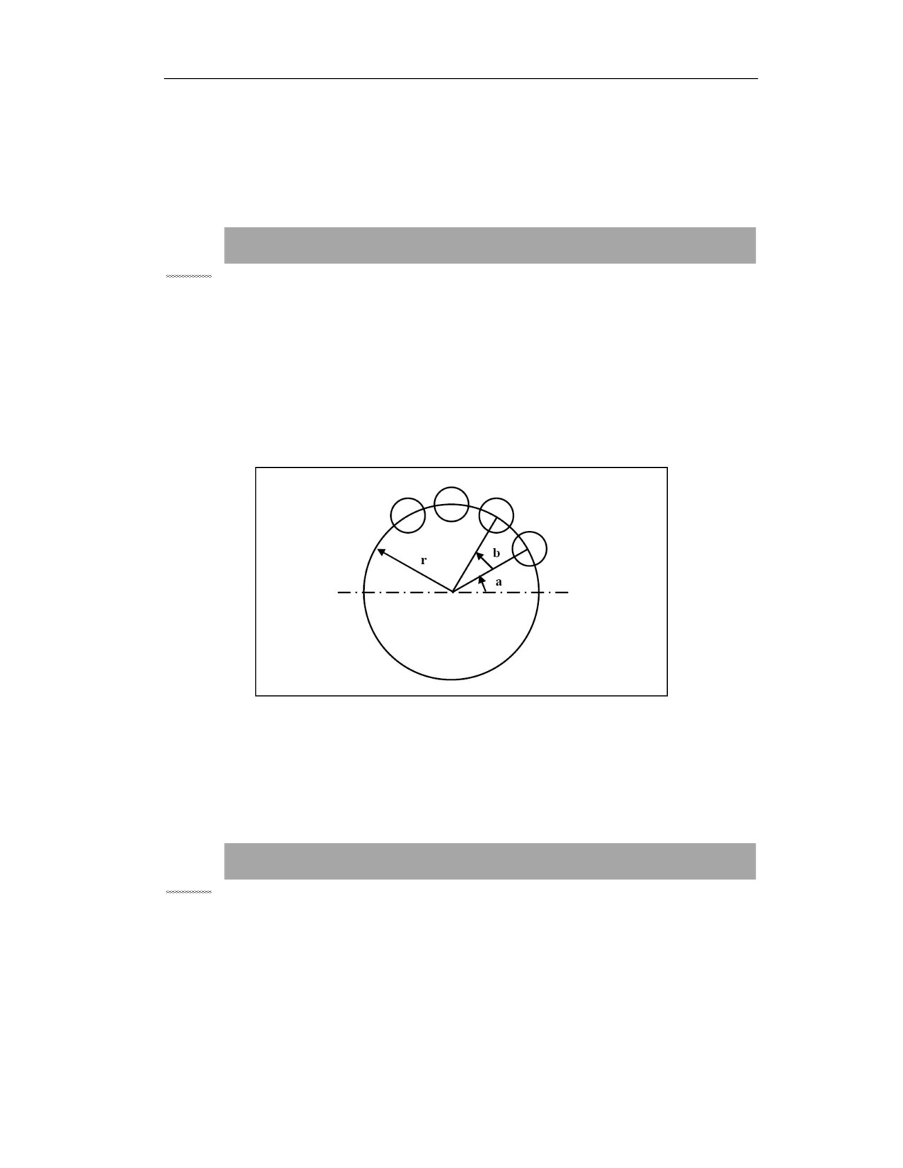
users to call in cycles, as shown in the figure below for bolt hole processing.
After storing the bolt hole machining program in the above figure created by the macro program
in the CNC, user can call this program to machine the bolt hole at any time, and just fill in the
bolt hole attributes such as the number of holes and deviation angle when calling. This is as if a
bolt hole function has been added to the CNC.
19.1.1 Variable
Function and Purpose
A certain address in the program is not directly specified with a numerical value, but with a
variable. When the program is running, the variable is assigned based on a predetermined situation
to improve the generality of the program.
In the macro program, user can use variables in the parameters of the axis movement distance,
such as G01 X[#54]F1000, at this time #54 is the variable, and user can perform some operations
such as assignment before calling.
337

Command Format
#○○○=□□□□
#○○○=[ Expression]
Variable
Description
Example
representation
#A
A is composed of numbers from 0 to 9
#21
Value A
#23
Expression Operation command Expression
#1+#2
#B(expression)
Function [expression]
COS[#3]
Note
It is not allowed to use variable names directly in user macro programs. Variables are designated
by the variable symbol (#) and the following variable number.
Description
Variable types
According to the purpose of variables, variables can be divided into local variables, global
variables, and system variables. In addition, the access attributes of different variables are also
different. Some variables are read-only, and some are readable and writable.
Constant
Some constants with constant values are defined in the system for users to use. The attributes of
these constants are read-only.
PI:Pi π
TRUE: True, used for conditional judgment, indicating that the condition is ture
FALSE: False, used for conditional judgment, indicating that the condition is not ture
Note
When the constant PI is used, due to the calculation error, it needs to be dealt with at the time of
ending conditions, otherwise an abnormal situation will occur.
Local Variable
Local variables refer to the variables used in the macro program. The local variable #i (i is a value,
such as #10) used in macro program A is called in the current state, which is different with the #i
used in macro program A called in other states. Therefore, when multiple levels of macros are
called, such as calling macro B from macro A, if the local variable used in macro A is incorrectly
used in macro B, the value will be destroyed.
338
The system provides #0 to #49 as current local variables, and their access attributes are readable
and writable.
The system provides 6 levels of nesting. The corresponding local variables of each level are as
follows. The access attributes of these local variables are readable:
#200~#249 Level 0 local variable
#250~#299 Level 1 local variable
#300~#349 Level 2 local variable
#350~#399 Level 3 local variable
#400~#449 Level 4 local variable
#450~#499 Level 5 local variable
Global variable
Different from local variables, global variables are commonly used between subprograms and
macro programs, and their values remain unchanged. That is, #i used in one macro is the same as
#i used in other macros. In addition, the public variable #i calculated by a certain macro can be
used in other macros.
The system provides #50 to #199 as global variables, and their access attributes are readable and
writable.
System variable
System variables are variables whose purposes are fixed in the system. There are 3 types of
attributes for the system variables: read-only, write-only, and read/write. The attributes varies with
system variables.
Undefined variable
The value of variables not defined in the system defaults to 0
Example:%1234
G54
G90G01 X10Y10F1000
X[#1]Y40
; The coordinate value of the workpiece coordinate system is (0, 40)
M30
User-defined variable
User-defined variable:500 to 999
50000 to 54999
#500 - #999
R/W
Global variable
#50000 - #54999
R/W
Global variable
Note
339

When machine user parameter 010091 "#500 - #999 user macro variable enable" is 1, #500 - #999
are valid user-defined variables. User-defined variables are saved after power off.
"USERMACCFG.XML" needs to be configured (configured based on usage requirements, too
many variables configured will occupy too much system storage space), and the configured file
is correctly imported into the system in the "Data Management-User Macro Variable Name"
interface.
USERMACCFG.XML(the file comes from the internal CNC system
:
<?xml version="1.0" encoding="GB2312"?><USERMACCFG version="1.0">
<item no="500" name="用户宏变量 1" type="FLOAT" />
<item no="501" name="用户宏变量 2" type="FLOAT" />
<item no="502" name="用户宏变量 3" type="FLOAT" />
<item no="503" name="用户宏变量 4" type="FLOAT" />
<item no="504" name="用户宏变量 5" type="FLOAT" />
<item no="505" name="用户宏变量 6" type="FLOAT" />
<item no="999" name="用户宏变量 500" type="FLOAT" />
<!--相关用户宏-->
<item no = "50000" name = "用户宏变量" type= "INT"></item>
<item no = "50001" name = "用户宏变量" type= "INT"></item>
<item no = "50002" name = "用户宏变量" type= "INT"></item>
<item no = "50003" name = "用户宏变量" type= "INT"></item>
<item no = "50004" name = "用户宏变量" type= "INT"></item>
<item no = "50005" name = "用户宏变量" type= "INT"></item>
<item no = "50100" name = "用户宏变量" type= "INT"></item>
</USERMACCFG>
Note
The numeric format in type needs to be configured correctly (FLOAT represents the data type of
floating point, and INT represents the data type of integer), otherwise the macro program cannot
run normally.
Channel-related variables
Variable number
Attribute
Description
Channel parameter
Channel 00:(00000 to 03999)
#0~#49
R/W
Current local variable
#50~#199
Reserved
#200~#249
R
Level 0 local variable
#250~299
R
Level 1 local variable
#300~#349
R
Level 2 local variable
#350~#399
R
Level 3 local variable
340

#400~#449
R
Level 4 local variable
#450~#499
R
Level 5 local variable
#1000~#1008
R
Machine position of current channel axis
(9-axis)
#1009
R
Diameter programming of lathe
#1010~#1018
R
Programmed machine position of current
channel axis (9-axis)
#1019
Reserved
#1020~#1028
R
Programmed workpiece position of current
channel axis (9-axis)
#1029
Reserved
#1030~#1038
R
Workpiece origin of current channel axis
(9-axis)
#1039
R
Coordinate system
#1040~#1048
R/W
G54 origin of current channel axis (9-axis)
#1049
R
G54 axis mask
#1050~#1058
R/W
G55 origin of current channel axis (9-axis)
#1059
R
G55 axis mask
#1060~#1068
R/W
G56 origin of current channel axis (9-axis)
#1069
R
G56 axis mask
#1070~#1078
R/W
G57 origin of current channel axis (9-axis)
#1079
R
G57 axis mask
#1080~#1088
R/W
G58 origin of current channel axis (9-axis)
#1089
R
G58 axis mask
#1090~#1098
R/W
G59 origin of current channel axis (9-axis)
#1099
R
G59 axis mask
#1100~#1108
R
G92 origin of current channel axis (9-axis)
#1109
R
G92 axis mask
#1110~#1118
R
Break-off position of current channel axis
(9-axis)
#1119
R
Break point axis mark
#1120~#1149
R/W
Modal variable of canned cycle
#1150~#1189
R
Groups 0 to 39 modal of G code
#1190
R
User-defined input
#1191
R
User-defined output
#1192~#1199
Reserved
#1200~#1209
R
AD input
#1210~#1219
R
DA output
#1220
R
M3/4/5
#1221
R
G94 F value
#1222
R
Tapping F value
#1223~#1226
R
Tapping spindle speed
#1227
R
Valid radius compensation D number
341
#1228
R
Valid length compensation H number
#1229
R
cmd_feed
#1300~#1308
R
Relative zero of current channel axis (9-
axis)
#1309
Reserved
#1310~1318
R
Programmed machine position of current
channel axis (9-axis)
#1319
Reserved
#1320~#1328
R
G28 intermediate point
#1329
R
G28 axis mask
#1330~#1338
R
G52 origin
#1339
Reserved
#1340~#1349
R
G31 measurement machine command
#1350~#1359
Reserved
#1360~#1369
R
G31 measurement machine actual
#1370~#1399
Reserved
#1400~#1408
R/W
G54 offset
#1409
Reserved
#1410~#1418
R/W
G55 offset
#1419
Reserved
#1420~#1428
R/W
G56 offset
#1429
Reserved
#1430~#1438
R/W
G57 offset
#1439
Reserved
#1440~#1448
R/W
G58 offset
#1449
Reserved
#1450~#1458
R/W
G59 offset
#1459~#3999
Reserved
Note
The variables corresponding to the origin and offset of the workpiece coordinate system G54 -
G59 in the current channel are both readable and writable, and are saved after power off.
Variables related to the extended coordinate system
Variable number
Attribute
Description
Channel variable
Channel 00:(40100 to 40639)
#40100~#40108
R/W
G54.1P1
#40109~#40117
R/W
G54.1P2
#40118~#40126
R/W
G54.1P3
#40127~#40135
R/W
G54.1P4
#40136~#40144
R/W
G54.1P5
#40145~#40153
R/W
G54.1P6
342

#40154~#40162
R/W
G54.1P7
#40163~#40151
R/W
G54.1P8
#40172~#40180
R/W
G54.1P9
#40181~#40189
R/W
G54.1P10
#40190~#40198
R/W
G54.1P11
#40199~#40207
R/W
G54.1P12
#40208~#40216
R/W
G54.1P13
#40217~#40225
R/W
G54.1P14
#40226~#40234
R/W
G54.1P15
#40235~#40243
R/W
G54.1P16
#40244~#40252
R/W
G54.1P17
#40253~#40251
R/W
G54.1P18
#40262~#40270
R/W
G54.1P19
#40271~#40279
R/W
G54.1P20
#40280~#40288
R/W
G54.1P21
#40289~#40297
R/W
G54.1P22
#40298~#40306
R/W
G54.1P23
#40307~#40315
R/W
G54.1P24
#40316~#40324
R/W
G54.1P25
#40325~#40333
R/W
G54.1P26
#40334~#40342
R/W
G54.1P27
#40343~#40351
R/W
G54.1P28
#40352~#40360
R/W
G54.1P29
#40361~#40369
R/W
G54.1P30
#40370~#40378
R/W
G54.1P31
#40379~#40387
R/W
G54.1P32
#40388~#40396
R/W
G54.1P33
#40397~#40405
R/W
G54.1P34
#40406~#40414
R/W
G54.1P35
#40415~#40423
R/W
G54.1P36
#40424~#40432
R/W
G54.1P37
#40433~#40441
R/W
G54.1P38
#40442~#40450
R/W
G54.1P39
#40451~#40459
R/W
G54.1P40
#40460~#40468
R/W
G54.1P41
#40469~#40477
R/W
G54.1P42
#40478~#40486
R/W
G54.1P43
#40487~#40495
R/W
G54.1P44
#40496~#40504
R/W
G54.1P45
#40505~#40513
R/W
G54.1P46
#40514~#40522
R/W
G54.1P47
#40523~#40531
R/W
G54.1P48
#40532~#40540
R/W
G54.1P49
343
#40541~#40549
R/W
G54.1P50
#40550~#40558
R/W
G54.1P51
#40559~#40567
R/W
G54.1P52
#40568~#40576
R/W
G54.1P53
#40577~#40585
R/W
G54.1P54
#40586~#40594
R/W
G54.1P55
#40595~#40603
R/W
G54.1P56
#40604~#40612
R/W
G54.1P57
#40613~#40621
R/W
G54.1P58
#40622~#40630
R/W
G54.1P59
#40631~#40639
R/W
G54.1P60
Note
The variables corresponding to the origin and offset of the workpiece coordinate system G54~G59
in the current channel are both readable and writable, and are saved after power off.
Variables related to tool
Tool data:#70000 to #89999
Each tool occupies 200 numbers, a total of 100 tools, a total of 20,000
numbers
Relative coding range of No. 0 tool:000 to 199
Relative coding range of No. 1 tool:200 to 399
Relative coding range of No. 99 tool:18000 to 19999
#70005
R
Lathe tool nose direction
#70006
R/W
Tool length of milling cutter or X offset
value of lathe tool
#70007
R
Y offset of lathe tool
#70008
R
Z offset of lathe tool
#70009
Reserved
#70010
Reserved
#70011
R/W
Tool radius of milling cutter or tool nose
radius of lathe tool
#70012~#70028
Reserved
#70029
R/W
Length wear of milling cutter or Z offset
wear of lathe tool
#70030
Y offset wear of lathe tool
#70034
R/W
Radius wear of milling cutter or X offset
wear of lathe tool
#70035~#70100
Reserved
#70101
R
Tool life monitoring type
#70104
R
Max. life of cutting time
#70105
R
Life of pre-warning cutting time
#70106
R
Life of current cutting time
344
#70107
R
Life of max. cutting times
#70108
R
Life of pre-warning cutting times
#70109
R
Life of actual cutting times
Note
The variables corresponding to the tool radius compensation value, length compensation value,
and wear value can be read and written, and can be saved after power off.
(F) Class A command (T)
#50000
X coordinate of tool measuring
#50003
Z coordinate of tool measuring
instrument calibration
instrument calibration
#[50006+N]
Avarage measured value of No.
Average measured value of No. N
#[51006+N]
N tool on Z
tool on X
#54005
Tool retraction amount
#54006
Tool nose angle A
#54007
Finishing times
#54008
(FUNAC) Q value
#54009
(F)R value
#54010
Undercut angle
#54011
Thread chamfer amount
#54012
G83 Axial drilling cycle
H1/H2 Retraction mode
#54013
G83 Retraction amount
#54014
G84 Tapping axis selection
#54015
G84 H1/H2 Retraction mode
#54016
G84 Retraction amount
#54017
G88 Tapping axis selection
#54990
Measuring
instrument
center
position X
#54992
Measuring instrument center
position Z
Note
The (F) Class A command (T) function in the CNC system occupies the above-mentioned user-
defined macro variables. Please do not use the above-mentioned user-defined macro variables.
Workpiece measurement F
Variable
Description
Variab
Description
number
le
numbe
r
#600
Distance from actual center to trigger
#630
Center position value in X plane or
point in X positive direction
X direction
#601
Distance from actual center to trigger
#631
Center position value in Y plane of
point in X negative direction
Y direction
#602
Distance from actual center to trigger
#632
Z plane position value
point in Y negative direction
#603
Distance from actual center to trigger
#633
Position offset value in X direction
point in Y positive direction
#604
Probe length value
#634
Position offset value in Y direction
#605
Eccentricity of probe in X direction
#635
Position offset value in Z direction
345

#606
Eccentricity of probe in Y direction
#636
Dimension value: width/diameter
#607
Trigger radius of probe in X direction
#637
Dimension offset vlaue
#608
Trigger radius of probe in Y direction
#638
Angle value (unit: degree)
#609
Second measurement speed of probe
Note
The workpiece measurement function in the CNC system occupies the above-mentioned user-
defined macro variables. If the debugger uses other user-defined macro variables when debugging
the workpiece measurement function, instead of the user-defined macro variables listed in the
above table, the debugger will replace or add them to the table, and inform and provide it to the
user. Please do not use the above user-defined macro variables.
Tool measurement
Variable
Description
Variable
Description
number
number
#642
Laser beam width of tool setter
#649
2nd measurement speed in tool
setting
#643
Tool setter laser on X
#650
Center position of tool setter on
X
#644
Tool setter on Y
#651
Center position of tool setter
on Y
#645
Height difference
1 (laser height-
#652
Absolute safety height of tool
base height)
setter
#646
Height difference
2 (base height-
#653
Max. allowable value for tool
workpiece height)
break detection
#647
Rapid traverse speed in tool setting
#654
Tool number of datum tool
#648
1st measurement speed in tool
#660
Datum tool length—relative
setting
tool setter surface
#661~#676
1~16 号刀,刀长相对对刀仪
表面 No.1 to 16 tools,
Note
The workpiece measurement function in the CNC system occupies the above-mentioned
user-defined macro variables. If the debugger uses other user-defined macro variables when
debugging the workpiece measurement function, instead of the user-defined macro variables
listed in the above table, the debugger will replace or add them to the table, and inform and
provide it to the user. Please do not use the above user-defined macro variables.
19.1.2 Operation Command
Function and Purpose
Arithmetic operators, functions and other operations can be flexibly used in macro programs,
which is very convenient to realize complex programming requirements. As shown in the table
346
below.
Operation
Operation
Meaning
type
command
#i = #i + #j
Addition, #i plus #j
Arithmetic
#i = #i - #j
Subtraction, #i minus #j
operation
#i = #i * #j
Multiplication, #1 times #j
#i = #i / #j
Division, #i divided by #j
#i EQ #j
(=)Equal to
#i NE #j
(≠)Not equal to
Conditional
#i GT #j
(>)Larger than
operation
#i GE #j
(≥)Larger than or equal to
#i LT #j
(<)Smaller than
#i LE #j
(≤)Smaller than or equal to
#i = #i & #j
Logic and
Logic
#i = #i | #j
Logic or
operation
#i = ~#i
Logic not
#i= SIN[#i]
Sine (unit: radians)
#i=ASIN[#i]
Arc sine
#i=COS[#i]
Cosine (unit: radians)
#i=ACOS[#i]
Arc cosine
#i=TAN[#i]
Tangent (unit: radians)
#i=ATAN[#i]
Arc tangent
#i=ABS[#i]
Absolute value
#i=INT[#i]
Round (round down)
#i=SIGN[#i]
Sign
#i=SQRT[#i]
Square root
Function
#i=#A POW[#i]
#A to the #i power
#i=LOG[#i]
Log
#i=PTM[#i]
Pulse revolutions mm
#i=PTD[#i]
Pulse revolution degree
#i=RECIP[#i]
Reciprocal
Exponent, an exponent
based
on
e
#i=EXP[#i]
(2.718)
#i=ROUND[#i]
Rounding
#i=FIX[#i]
Round down
#i=FUP[#i]
Round up
Note
When using trigonometric functions, pay attention to check "000349 trigonometric function
selection, 0: radian, 1: angle", and adjust the calculation during programming based on the
parameters.
347
Example
Example 1
A sum of 1 to 100
O1234
#1=0;
Initial value of solution
#2=1;
Initial value of addend
N1 WHILE[#2 LE 100] ;The addend cannot exceed 100, otherwise jump to N2 after
ENDW
#1 =#1 + #2;
Calculate solution
#2 =#2 +1;
Next addend
ENDW;
Transfer to N1
N2 M30;
Program end
348
19.1.3 Macro Statement
Function and Purpose
The following blocks are macro statements:
1) Blocks containing variables and operation commands;
2) Blocks containing conditional judgment statements or cycle statements;
3) Blocks containing macro program calling commands.
Description
Expression
Any calculation formulas including signs such as "+", "-", "*", "/", "[", "]", SIN, etc. are referred
to as expressions. Shown as follows
1.
-#4
2.
SIN[#4+#5]*COS[[#4+#5]/#6]
Note
The priority in [] is higher than +-*/, for example [[#4+#5]/#6], first calculate [#4+#5], then
calculate
/#6. For expressions, in order to ensure the correctness of calculations, it is
recommended to use [] for expressions, such as [-#5]. The usage such as -[#5] is not recommended.
Assignment statement
Transferring the value of a constant or an expression to a macro variable is referred to as an
assignment, and this statement is referred to as an assignment statement, as follows:
#5 = 145 / SQRT[3] * COS[40*PI/180]
#6 = 123
Conditional judgement statement
Two kinds of conditional judgement statements are supported:
IF [Conditional expression];
Type 1
……
ENDIF
IF [Conditional expression];
Type 2
……
ELSE
……
ENDIF
349
For the conditional expressions in the IF statement, user can use simple conditional expressions
or compound conditional expressions, as shown in the following example:
When #4 is equal to #5, assign 1 to #6
IF [#4 EQ #5]
#6 = 1
ENDIF
When #4 is equal to #5, and #6 is equal to #7, assign 2 to #6
IF [#4 EQ #5] AND [#6 EQ #7]
#6 = 2
ENDIF
When #4 is equal to #5, or #6 is equal to #7, assign 1 to #6, otherwise assign 2 to #6
IF [#4 EQ #5] OR [#6 EQ #7]
#6 =1
ELSE
#6 = 2
ENDIF
Cycle statement
The conditional expression is specified after WHILE. When the specified conditional expression
is satisfied, execute the program from WHILE to ENDW, and execute the cycle until the
conditional expression is not satisfied. When the specified conditional expression is not met, exit
the WHILE cycle and execute the program blocks after ENDW.
The calling format is as follows,
WHILE [Conditional expression]
……
ENDW
Infinite cycle
When the conditional expression in WHILE is always true, an infinite cycle can be realized. For
example,
WHILE [TRUE];or WHILE [1]
……
ENDW
Jump statement
GOTO _
Use GOTO to jump to the specified label
350
GOTO is followed by a number. For example, with GOTO 5, the system jumps to the N5 block
(N5 must be written at the beginning of the block).
Nesting
For IF statements or WHILE statements, the system allows nested statements, but with certain
restrictions, as follows:
IF statement supports up to 6 levels of nested calls, and the system will issue an error if 6 levels
are exceeded;
The WHILE statement supports up to 6 levels of nested calls, and the system will issue an error
if 6 levels are exceeded;
The system supports mixed use of IF statement and WHILE statement, but the matching
relationship between IF-ENDIF and WHILE-ENDW must be met.
Example
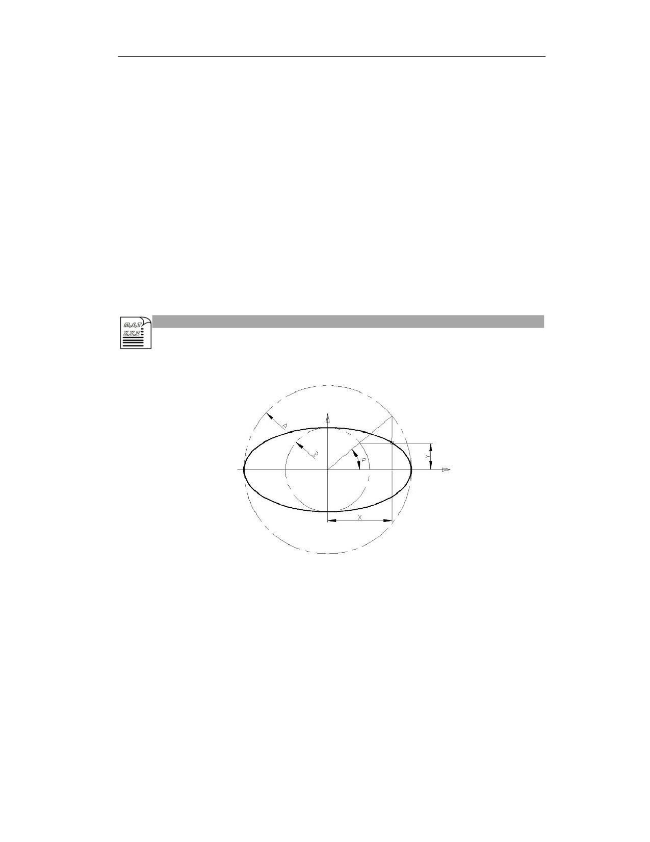
Edit the ellipse processing program (ellipse expression: X=A×COSα; Y=B×SINα).
%0001
#0=5
; Define the tool radius R value
#1=20
; Define A value
#2=10
; Define B value
#3=0
; Define the initial value of the step angle α, unit: degree
G92 X0 Y0 Z10
M3S1000
G00 X[2*#0+#1] Y[2*#0+#2]
G01 Z0
G41 X[#1]D01F200
WHILE #3 GE [-360]
G01 X[#1*COS[#3*PI/180]] Y[#2*SIN[#3*PI/180]]
#3=#3-5
351
ENDW
G01X[#1]Y0
G01 G91 Y[-2*#0]
G90 G00 Z10
G40 X0 Y0
M30
352
19.2
Macro Program Calling
Function and Purpose
The system supports the following three ways to call the macro program:
(1) Non-modal call: G65
(2) Call macro program with G code
(3) Call macro program with M command
19.2.1 Argument Specification Rules
Function and Purpose
Argument specification rules
In the user macro program, when the argument needs to be transmitted as a local variable, the
actual argument value must be specified after the address.
When the user calls the macro program, the system will copy the content of the arguments (A to
Z) in the current block to the corresponding local variables #0 - #25 of the current layer of the
corresponding user macro program, and also copy the absolute position of the nine axes
(XYZABCUVW) of the workpiece coordinate system in the current channel to the local variables
#30 - #38 in the current channel.
Macro
Argument
Macro
Argument
Macro
Argument
variable
name
variable
name
variable
name
#0
A
#1
B
#2
C
#3
D
#4
E
#5
F
#6
G
#7
H
#8
I
#9
J
#10
K
#11
L
#12
M
#13
N
#14
O
#15
P
#16
Q
#17
R
#18
S
#19
空
#20
U
#21
V
#22
W
#23
X
#24
Y
#25
Z
#26
Reserved
#27
Reserved
#28
Reserved
#29
Reserved
X axis
Y axis
Z axis
#30
#31
#32
position
position
position
A axis
B axis
C axis
#33
#34
#35
position
position
position
U axis
V axis
W axis
#36
#37
#38
position
position
position
353

Example
Macro variable is defined and determined
Format: AR[#Variable number]
Return value: 0: Indicates that the variable is not defined;
90: Indicates that the variable is defined as absolute mode G90;
91: Indicates that the variable is defined as incremental mode G91
Note: The system macro AR[] is used to determine whether the macro variable is defined and
defined as incremental or absolute mode;
Example
%1234
G92X0Y0Z0
M98P9990X20Y30Z40
M30
%9990
IF [AR[#23] EQ 0] OR [AR[#24] EQ 0] OR [AR[#25] EQ 0]; If the X, Y or Z value is not
defined, it returns.
M99
ENDIF
IF AR[#23] EQ 90
;If X value is in absolute mode G90
#23=#23-#30
;X value is converted to be in incremental mode, #30 is the absolute
coordinate of X
ENDIF
……
M99
19.2.2 Non-modal Call (G65)
Function and Purpose
When G65 is specified, the user macro program specified by the parameter P is called, and at the
same time, the arguments and the variables needed by the user macro program are transferred to
the user macro program.
Command Format
G65 P_ L_ [Argument address word];
Parameter
Meaning
P
Program number required to be called
L
Number of repeated calls
354

Argument address
Data that the user needs to transfer to the
word
macro program
Note
(1)G65 is a non-modal command. User needs to specify G65 in this line every time the macro
program is called;
Example
Example
%0032
G54G0X0Y0Z100
M3S1000
G65P100L5X50Y50Z-30R5F200
G00X50Z10
M30
%100
G01X[#23]Y[#25]F[#5]
G81Z[#25]R[#17]F[#5]
G0Z50
M30
19.2.3 Calling Macro Program with G Code
Function and Purpose
In addition to calling macro program with non-modal code (G65), user can also call the macro
program in the form of G code. Currently, the macro program in the form of G code canned cycle
can only be called for canned cycle. For the specific code, please refer to the drilling and milling
chapter and this chapter 17.2.3.
Function
Call the user-defined subprogram in user canned cycle with G command.
Command Format
G_:
Parameter
Meaning
G
The number of the called subroutine in USERDEF.CYC
(Arabic numerals)
Note:
1) The system provides G1000 to G1999 to call the user-defined subprogram in the canned cycle
355
with G command.
2)G1000 to G1999 respectively correspond to the called subprogram number (in Arabic
numerals) %1000 to %1999 in USERDEF.CYC, for example, G1010 corresponds to the called
subprogram number %1010 in USERDEF.CYC.
Example
Add user canned cycle %1010 in USERDEF.CYC
%1010;
G01 X30 Y0 F3000
#0 = 0.0
#1 = 30.0
#2 = 2.1
#3 = 3.4
WHILE [#0 LE 360]
G1 X[ #1 * COS[#0*PI/180]]Y[ #1 * SIN[#0*PI/180]]F3000
#0 = #0 + 0.1
ENDW
G01X30Y0F3000
G80
M99
%1244 Main program
G92X0Y0Z50
G01X30Y-20F3000
M3S3000
Z0F1000
G1010 (Call user-defined canned cycle)
G01Y20F3000
G00Z50
M30
19.2.4 Calling Macro Program with M Command
Function and Purpose
Calling macro program with M command is realized by calling a custom subprogram with an M
code.
There are two forms as described in the "Command Format" below. For the macro program calling
with M98, when M98 is executed, first call the subprogram number of the internal subprogram.
If there is no such subprogram number, search for the number of the external subprogram. If there
is no such subprogram in both, an error will be reported; for calling macro program with M code,
356

can the user-defined subprogram in the canned cycle can be called.
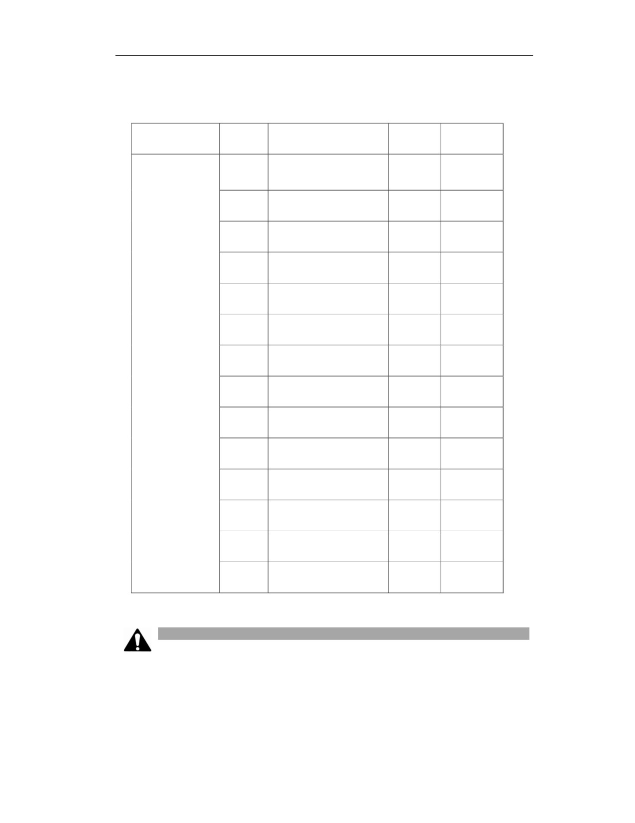
The corresponding M code parameter settings of user-defined subprogram in canned cycle are
shown in the following figure. The user-defined parameters 010360 to 010373 respectively
correspond to the %1007 to %1020 subprogram in USERDEF.CYC.
Command Format
M98 P_;
Parameter
Meaning
P
The program number to be called in the program
Note: when M98 is specified, the user macro program following P parameter is called.
M_;
Parameter
Meaning
M
The input value of user-defined parameter
Example
The parameter 010360 M Code Corresponding to User Canned Cycle G1007 is set as 13, that is,
the %1007 program in USERDEF.CYC can be called by the M13 command in the processing
program.
%1007; Add user-defined subprogram 1007 in the USERDEF.CYC file
G59
G64G01 X30 Y0 F3000
#0 = 0.0
#1 = 30.0
WHILE [#0 LE 360]
G1 X[ #1 * COS[#0*PI/180]]Y[ #1 * SIN[#0*PI/180]]F3000
#0 = #0 + 0.1
ENDW
G01X30Y0F3000
G80
M99
%1234; Main program
G54
G1X0Y0Z50
G01X30Y-20F3000
M3S3000
Z0F1000
M13; Call the matching 1007 subprogram with M13
357
G01Y20F3000
G00Z50
M30
Parameter type
Paramet
Parameter name
Value
Activation
er
010360
M code corresponding to
13
Save
user canned cycle G1007
010361
M code corresponding to
0
Save
user canned cycle G1008
010362
M code corresponding to
0
Save
user canned cycle G1009
010363
M code corresponding to
0
Save
user canned cycle G1010
010364
M code corresponding to
0
Save
user canned cycle G1011
010365
M code corresponding to
0
Save
user canned cycle G1012
010366
M code corresponding to
0
Save
Machine user
user canned cycle G1013
parameter
010367
M code corresponding to
0
Save
user canned cycle G1014
010368
M code corresponding to
0
Save
user canned cycle G1015
010369
M code corresponding to
0
Save
user canned cycle G1016
010370
M code corresponding to
0
Save
user canned cycle G1017
010371
M code corresponding to
0
Save
user canned cycle G1018
010372
M code corresponding to
0
Save
user canned cycle G1019
010373
M code corresponding to
0
Save
user canned cycle G1020
Note
(1) The above canned cycle, rotation/mirroring/scaling and G91 cannot be used at the same time.
(2) When using the M command to call a subprogram, it is necessary to add G80 before M99 at
the end of the program.
358

19.2.5 Classification of Subprogram
Function and Purpose
Internal subprogram
The called program which is in the same file with the main program is referred to as internal
subprogram.
External subprogram
The called program is stored separately in another file, which is referred to as external subprogram.
The file name of the external subprogram must start with the letter O.
Example
Example for internal subprogram
The G code file name is OTEST, and %111 is an internal subprogram, which is in the same file
as the main program %1001 and is called by M98 in the main program.
%1001; Main program
G92 X0 Y0 Z50
G91 G01 Z10 F400
M98 P111; Call subprogram 111
G4X1
M30
%111; Subprogram
G01X10Y10Z10
…
G80
M99
Example for external subprogram
The G code file name is OTEST, and the subprogram file name is O123.
Main program
Subprogram 0123
%1001
%1234;
G92 X0 Y0 Z50
G01X10Y10Z10
G91 G01 Z10 F400
…
M98 P123; Call subprogram 0123
G80
G4X1
M99
M30
359