HNC8 Series CNC Controller. Programming Manual (V2.4) - page 7
same time as the first positioning action, and then the system processes the next boring
action;
When the number of repetitions L is specified, the M code is only executed for the first
hole, and the M code is not executed for the second or later holes;
When the tool length offset (G43, G44 or G49) is specified in the canned cycle, the
offset will be added while positioning to the R point;
Example
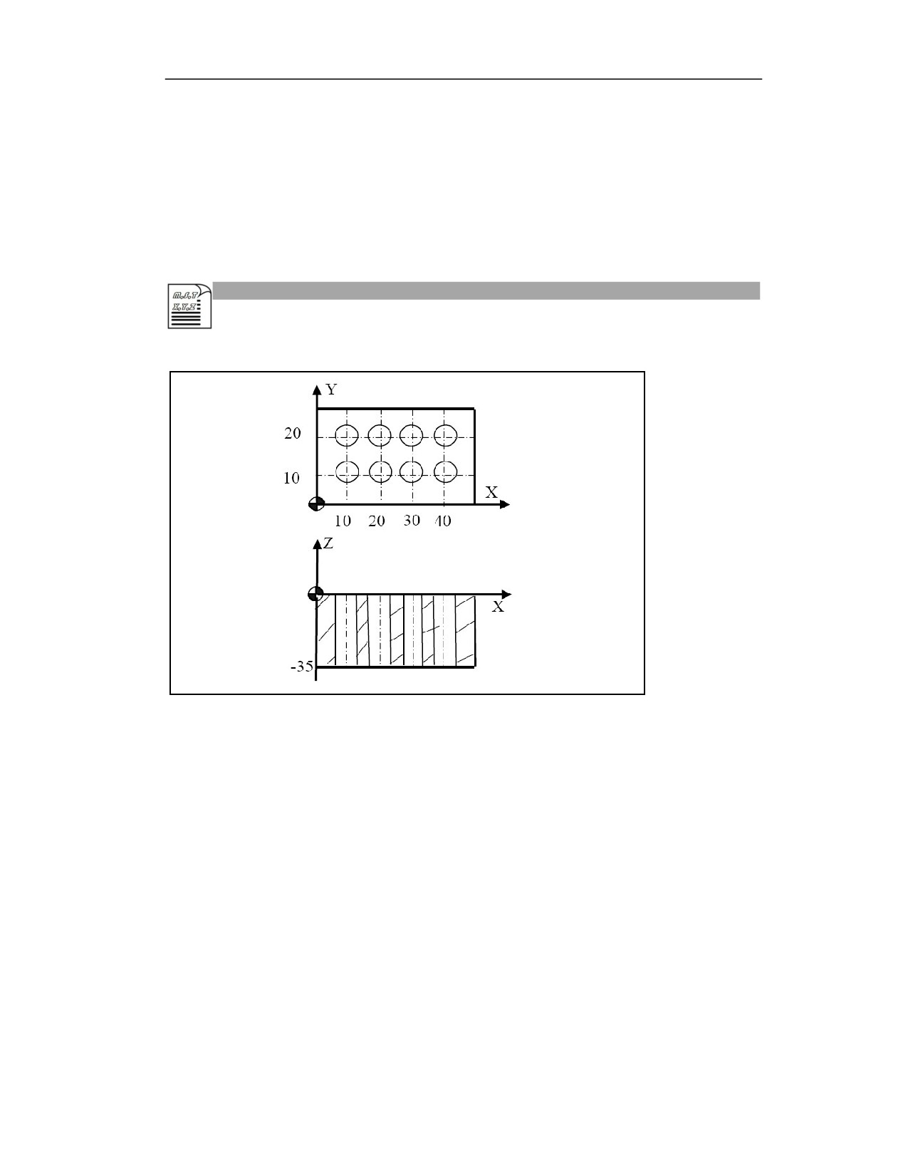
Machine the hole as shown below,
Example 1 (absolute programming, return to R level)
%3341
N10 G54 G90 G0 X0 Y0 Z80; Establish coordinate system, move to the safe initial point
N20M03 S600; Spindle rotates CW
N30G00 Z20; Position to initial level
N40 G99 G85 X10Y10Z-35 R5 P500 F100; After positioning, complete boring 1, then
return to R level
N50X20; After positioning, complete all boring, then return to R level
N60 X30
N70 X40
N80 Y20
N90 X30
N100 X20
N110 X10
24
N120 G80; Cancel G85 boring cycle
N130 G91G28 X0 Y0 Z0; Return to reference point
N140 M30;Program end
Example 2 (absolute and incremental mixed programming, return to the initial level)
%3343
N10 G54 G90 G0 X0 Y0 Z80; Establish coordinate system, move to the safe initial
point
N20 M03 S500; Spindle rotates CW
N30 G0 Z20; Position to initial level
N40 G98 G85 X10 Y10 Z-35 R5 P500 F100; After positioning, complete boring 1,
then return to R level
N50 G91 X10 L3; Increment X10 in turn to complete boring 3 holes, and then return
to the initial level
Y10
X-10 L3
N60 G80; Cancel G85 boring cycle
N70 G28 G91 X0 Y0 Z0; Return to reference point
N80 M30;Program end
Note
(1) Axis switching: Before switching the boring axis, the canned cycle must be cancelled.
(2) Modality: G85 command data is stored as modal data, and the same data can be omitted.
(3) Boring: Drilling is not performed in the block that does not include X, Y, Z, R or any other
additional axis. If the moving position of Z is zero, this command is not executed.
(4) Cancel: Do not specify the G codes of group 01 (G00 to G03, etc.) in the G85 block. Otherwise,
G85 will be cancelled.
(5) Tool position offset: In the boring canned cycle mode, the tool position offset is ignored.
15.10
Boring Cycle (G86)
Function and Purpose
The action performed by G86 is the same as that of G81, but the spindle stops at the bottom of
the hole and then quickly retracts. It is mainly used for low precision boring.
Command Format
(G98/G99) G86 X_ Y_ Z_ R_ F_ L_;
24
Parameter
Meaning
The absolute position of the hole in absolute programming(G90), and the distance
X Y
from the current position to the hole position in incremental programming(G91);
The absolute position of hole bottom in absolute programming (G90); the
Z
distance from hole bottom to R point in incremental programming (G91);
The absolute position of R point in absolute programming (G90); the distance
R
from R point to initial level in incremental programming (G91);
F
Cutting feedrate
L
Number of repetitions (can be omitted when L=1)
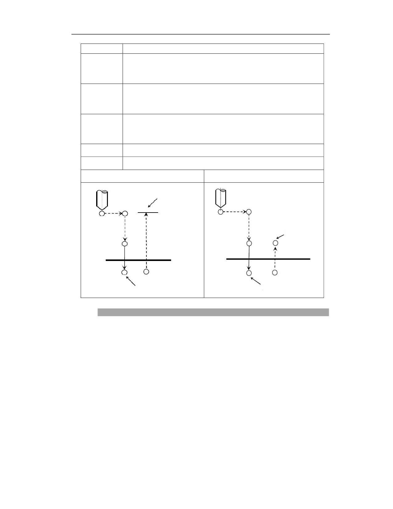
G86(G98)
G86(G99)
Spindle rotation CW
Initial level
R point level
R point
R point
Z point
Z point
Spindle stop
Spindle stop
Description
Action
After positioning along X-axis and Y-axis, the tool position quickly moves to point B above the
hole center;
Move close to the workpiece surface, and reach to R point;
Drill downward at F speed;
Reach to Z point of hole bottom;
Spindle stops rotating;
Retract upward to R point (G99) or B point (G98)
Spindle resumes CW rotation.
Spindle rotation
24
Rotate spindle with auxiliary function (M code) before using G86.
When continuously performing the drilling with a short distance from the hole position and the
initial level to the R point level, the spindle may not be able to rotate normally before entering the
hole cutting action. In this case, do not specify the number of repetitions L, and user needs to
insert GO4-based pause before each drilling action to let time out.
Tool length compensation
When the tool length compensation (G43, G44, G49) is specified in drilling canned cycle, this
compensation should be used at the time of positioning to R point.
Auxiliary function
When G86 command and M code are specified in the same block, the M code is executed during
the initial positioning. When the number of repetitions L is specified, the above actions will be
executed only the first time, and M codes will not be executed after the second time.
Example
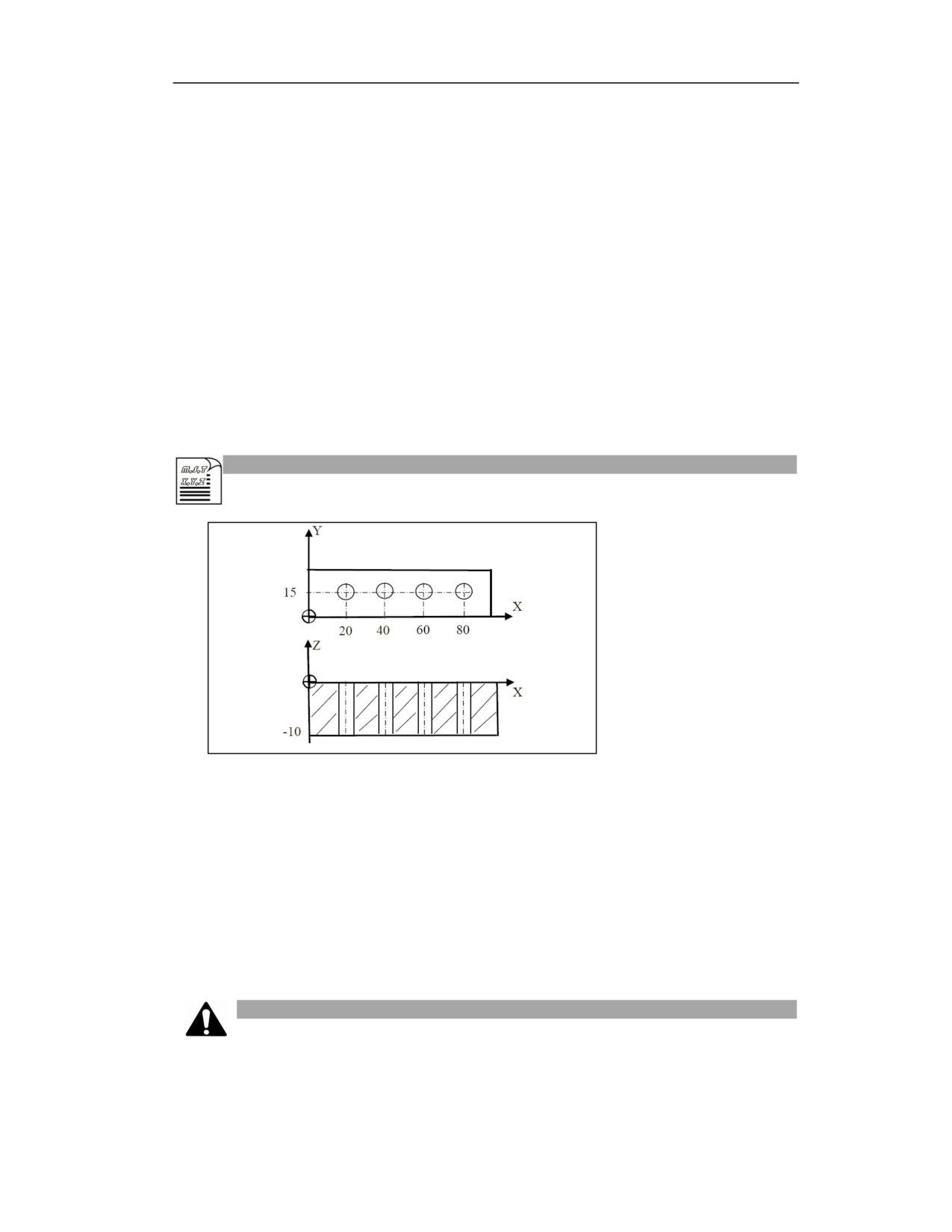
Example 1:
%3353; Reaming with a reamer
G54G00X0Y0Z50; Establish coordinate system, reach to the safe starting point
M3 S2000; Spindle starts
G99 G86G90X20Y15R20 Z-10 F120; After positioning, drill hole 1, and return to R level
G91 X20 L3; Ream holes 2, 3, 4 in turn, and return to the R level after each hole is milled
G80 G91 G28 X0 Y0 Z0; Cancel G86 boring cycle, return to the reference point
M30; Program end
Note
24
(1) Cancel canned cycle before switching drilling axis.
(2) The drilling axis must be Z axis in G17 plane.
(3) If the moving position is zero on Z, this command will not be executed.
(4) G86 data is saved as the modal data, and the same data can be omitted.
(5) Z point must be lower than R level, otherwise the alarm will be issued.
(6) Drilling is not performed in the blocks that not includes X, Y, Z, R or any other additional axis.
(7) The tool position offset is omitted in the drilling canned cycle mode.
(8) Do not specify the G code (G00-G03) of group 01 in the G86 block; otherwise, G86 will be
cancelled.
15.11
Reverse Boring Cycle (G87)
Function and Purpose
This command is generally used for boring the hole with small upper surface and large lower
surface, and Z point at hole bottom is generally above the reference point R, which is different
from other commands.
Command Format
(G98/G99) G87X_ Y_ Z_ R_ I_ J_ P_ F_ L_;
Parameter
Meaning
The absolute position of the hole in absolute programming(G90), and the distance
X Y
from the current position to the hole position in incremental programming(G91);
The absolute position of hole bottom on Z in absolute programming (G90); the
Z
distance from hole bottom to R point in incremental programming (G91);
The absolute position of R point in absolute programming (G90); the distance
R
from R point to initial level in incremental programming (G91);
I
Offset amount on X axis;
J
Offset amount on Y axis;
P
Dwell time at hole bottom (unit: ms)
F
Cutting feedrate;
L
Number of repetitions (can be omitted when L=1);
24
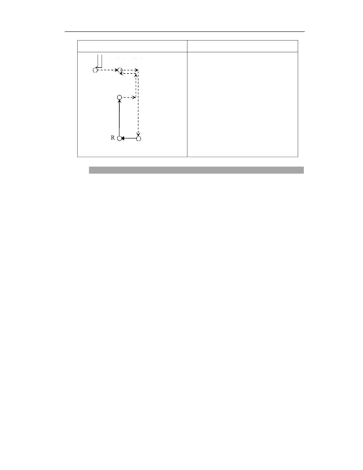
G87(G98)
G87(G99)
Initial point offset (I, J)
Z point
Positioning R point
Unavailable
Reverse offset (I, J)
Description
Actions
Tool position point moves to B point above hole center in rapid traverse, after positioning along
X axis and Y axis
Spindle orientates and stops rotation
The boring tool moves I or J in the opposite direction of tool nose;
Move to R point in rapid traverse
The boring tool moves I or J in the positive direction of tool nose, tool position point returns to
hole center X, Y
Spindle rotates CW
Boring upward at F speed, reach to Z point at hole bottom;
Dwell P ms at hole bottom (spindle keeps rotating)
Spindle orientates and stops rotating
Tool moves I or J in the opposite direction of the tool nose;
Retract to B point (G98) upward in rapid traverse
Move I or J in the positive direction of tool nose, tool position point returns to B point above hole
center
Spindle restores to CW rotation.
Spindle rotation
Rotate spindle with auxiliary function (M code) before using G87.
24
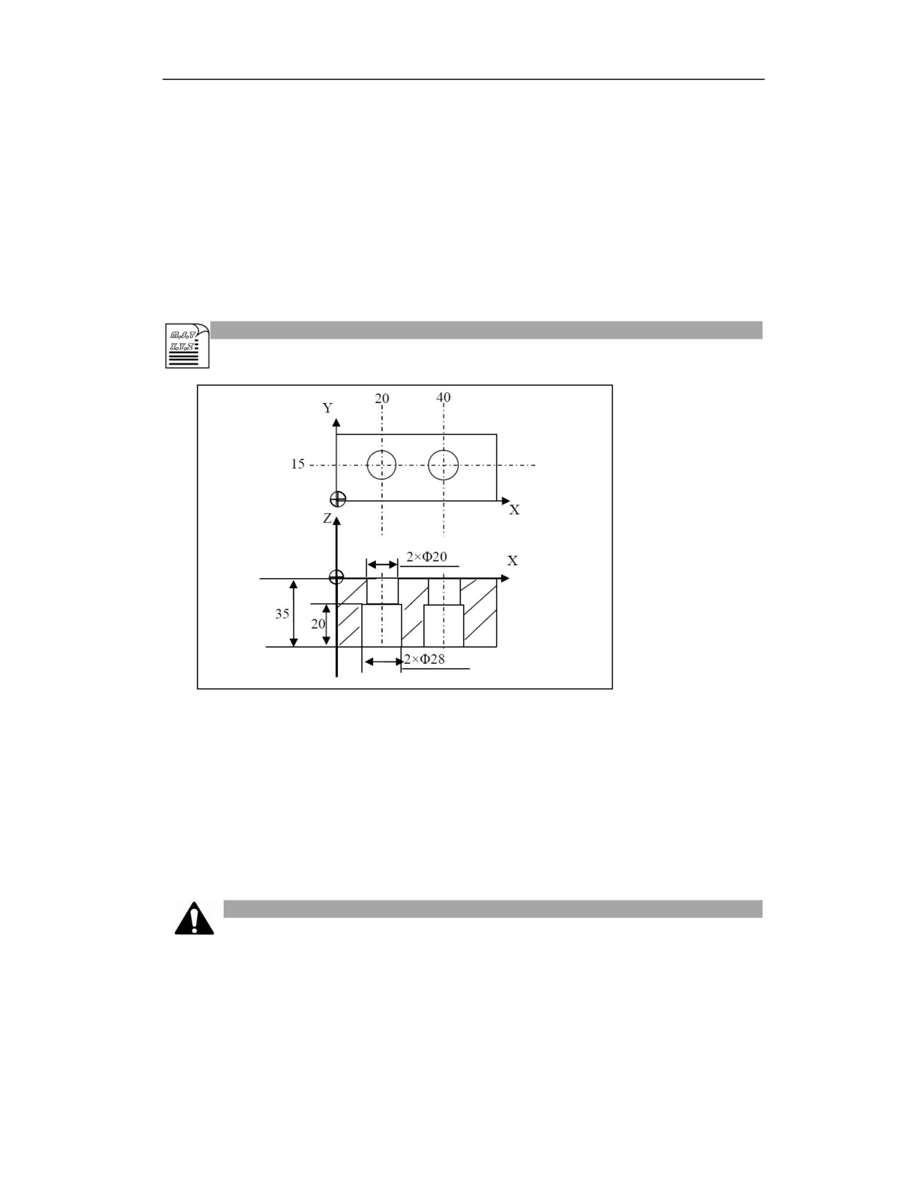
Tool length compensation
When the tool length compensation (G43, G44, G49) is specified in drilling canned cycle, this
compensation should be used at the time of positioning to R point.
Auxiliary function
When G87 command and M code are specified in the same block, the M code is executed during
the initial positioning. When the number of repetitions L is specified, the above actions will be
executed only at the first time, and M codes will not be executed after the second time.
Example
%3355
G54G0X0Y0Z50;Establish coordinate system, reach to safe starting point
M03 S600; Spindle starts
G54G0Y15
G98G87G90 X20I5R-40 P2000 Z-15 F120; Bore hole 1 after positioning
G91 X20; Bore hole 2 after positioning
G80 G91 G28 X0 Y0 Z0; Cancel G87 reverse cycle, return to reference point
M30; Program end
Note
(1) Cancel canned cycle before switching drilling axis.
(2) The drilling axis must be Z axis in G17 plane.
(3) If the moving position is zero on Z, this command will not be executed.
(4) Z point must be higher than R level, otherwise the alarm will be issued.
24
(5) G87 data is saved as the modal data, and the same data can be omitted.
(6) G87 can only use G98.
(7) Rotate spindle with the corresponding M code before using G87.
(8) Drilling is not performed in the blocks that not includes X, Y, Z, R or any other additional axis.
(9) The tool position offset is omitted in the drilling canned cycle mode.
(10) Do not specify the G code (G00-G03) of group 01 in the G87 block; otherwise, G87 will be
cancelled.
15.12
Boring Cycle (Manual) (G88)
Function and Purpose
With this command, the position of the initial point B or reference point R is memorized before
boring. When the boring tool automatically processes to the bottom of the hole, the machine stops
running, and the working mode is manually changed to JOG. After moving radially in the opposite
direction of the tool nose for a certain distance, the tool moves to above the height of point B or
point R and avoids the workpiece. Then the working mode is restored to auto, the program is cycle
restarted, and the tool position point returns to point B or point R. General milling machines can
complete fine boring with this command without the spindle exact stop function.
Command Format
G98(G99)G88 X_ Y_ Z_ R_ P_ F_ L_;
Parameter
Meaning
The absolute position of the hole in absolute programming(G90), and the distance
X Y
from the current position to the hole position in incremental programming(G91);
The absolute position of hole bottom on Z in absolute programming (G90); the
Z
distance from hole bottom to R point in incremental programming (G91);
The absolute position of R point on Z in absolute programming (G90); the
R
distance from R point to initial level in incremental programming (G91);
P
Dwell time at hole bottom (unit: ms)
F
Feedrate of boring;
Number of repetitions
(generally for multi-hole processing, X and Y are
L
incremental values)
G88(G98)
G88(G99)
24
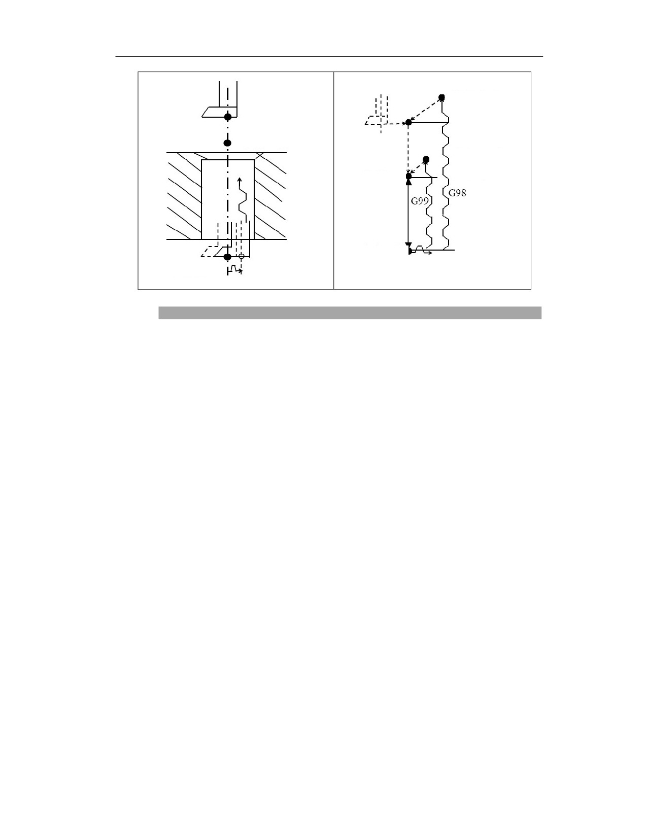
Spindle rotates CW
after B point is
Initial point B
returned
Reference point R
Spindle rotates CW
after B point is
returned
Reference point R
Hole bottom Z point
Hole bottom Z point
Delay at hole bottom, spindle stop
Description
Action
(1) The tool position point moves to B point above hole center after positioning along X axis and
Y axis;
(2) Move close to workpiece surface, reach to R point;
(3) Boring downward at F speed, reach to Z point at hole bottom;
(4) Dwell Pms at hole bottom (spindle keeps rotating);
(5) Spindle stops;
(6) In JOG mode, tool moves radially in the opposite direction of the tool nose for a certain
distance, reaches to above the height of B point or R point, avoiding workpiece;
(7) Press cyclestart button in auot mode, the tool moves to R point (G99) or B point (G98) in rapid
traverse;
(8) Spindle restores to rotation CW automatically;
Spindle rotation
Rotate spindle with auxiliary function (M code) before using G88.
Tool length compensation
When the tool length compensation (G43, G44, G49) is specified in drilling canned cycle, this
compensation should be used at the time of positioning to R point.
Auxiliary function
When G87 command and M code are specified in the same block, the M code is executed during
the initial positioning. When the number of repetitions L is specified, the above actions will be
24
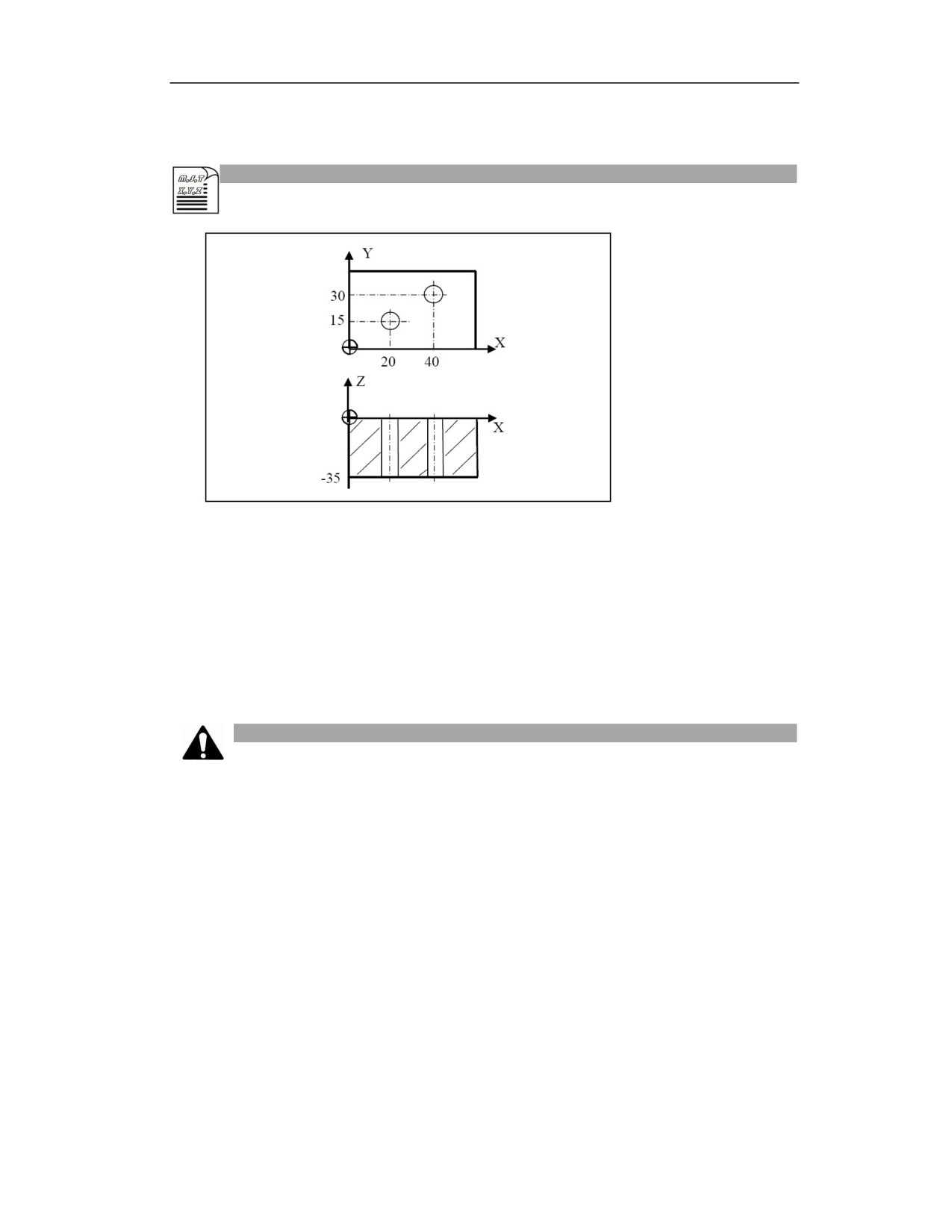
executed only for the first time, and M codes will not be executed after the second time.
Example
%3357
G54G01X0Y0Z50;Boring with a single-edge boring tool
M03 S600;Spindle starts
G98G88G90 X20Y15R5 P2000Z-40F100;After positioning, drill hole 1, return to R level,
pause 2 seconds at hole bottom
G99 G91 X20 Y15;After positioning, drill hole 2, return to initial level
G80 G28 G91 X0 Y0 Z0;Cancel G88, return to reference point
M30;Program end
Note
(1) Cancel canned cycle before switching drilling axis.
(2) The drilling axis must be Z axis in G17 plane.
(3) If the moving amount is zero on Z, this command will not be executed.
(4) Z point must be lower than R level, otherwise the alarm will be issued.
(5) G88 data is saved as the modal data, and the same data can be omitted.
(6) If G99 is used, manually move the tool to the position higher than R point.
(7) If G98 is used, manually move the tool to the position higher than R point.
(8) Use corresponding M code to rotate spindle before using G88.
(9) Drilling is not performed in the blocks that not includes X, Y, Z, R or any other additional axis.
(10) The tool position offset is omitted in the drilling canned cycle mode.
24
(11) Do not specify the G code (G00-G03) of group 01 in the G88 block; otherwise, G88 will be
cancelled.
15.13
Boring Cycle (G89)
Function and Purpose
The cycle is for boring.
Command Format
(G98/G99) G89 X_ Y_ Z_ R_ P_ F_ L;
Parameter
Meaning
The absolute position of the hole in absolute programming(G90), and the distance
X Y
from the current position to the hole position in incremental programming(G91);
The absolute position of hole bottom in absolute programming (G90); the
Z
distance from hole bottom to R point in incremental programming (G91);
The absolute position of R point in absolute programming (G90); the distance
R
from R point to initial level in incremental programming (G91);
P
Dwell time at hole bottom (unit: ms)
F
Cutting feedrate
Number of repetitions (usually used for multi-hole processing, so X or Y should
L
be an incremental value)
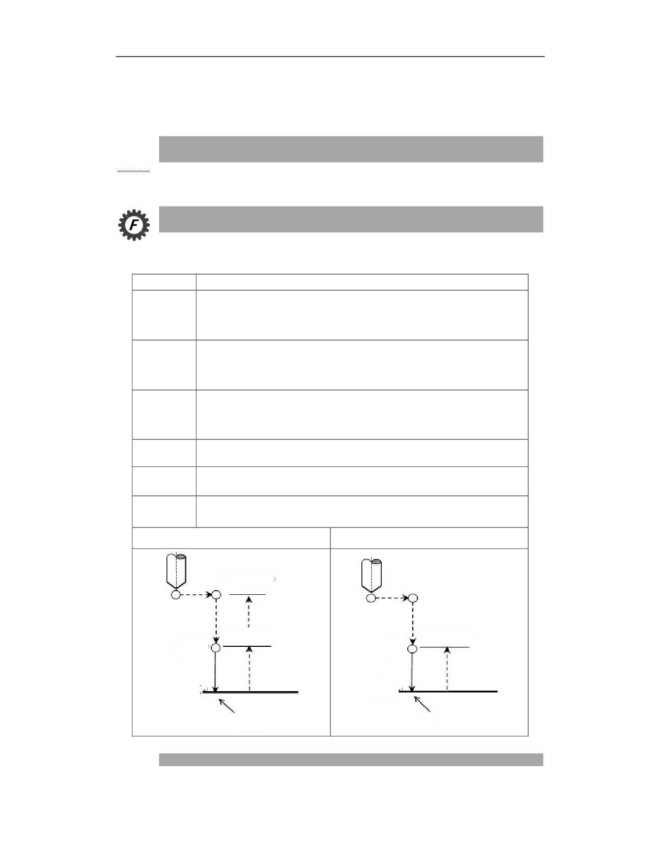
G89(G98)
G89(G99)
Initial level
R point level
R point level
R point
R point
Z point
Z point
Dwell
Dwell
Description
25
Actions
This cycle is similar as G86, and the dwell is performed at hole bottom.
Spindle rotation
Rotate spindle with auxiliary function (M code) before using G89.
Auxiliary function
When G89 command and M code are specified in the same block, the M code is executed during
the initial positioning. When the number of repetitions L is specified, the above actions will be
executed only for the first time, and M codes will not be executed after the second time.
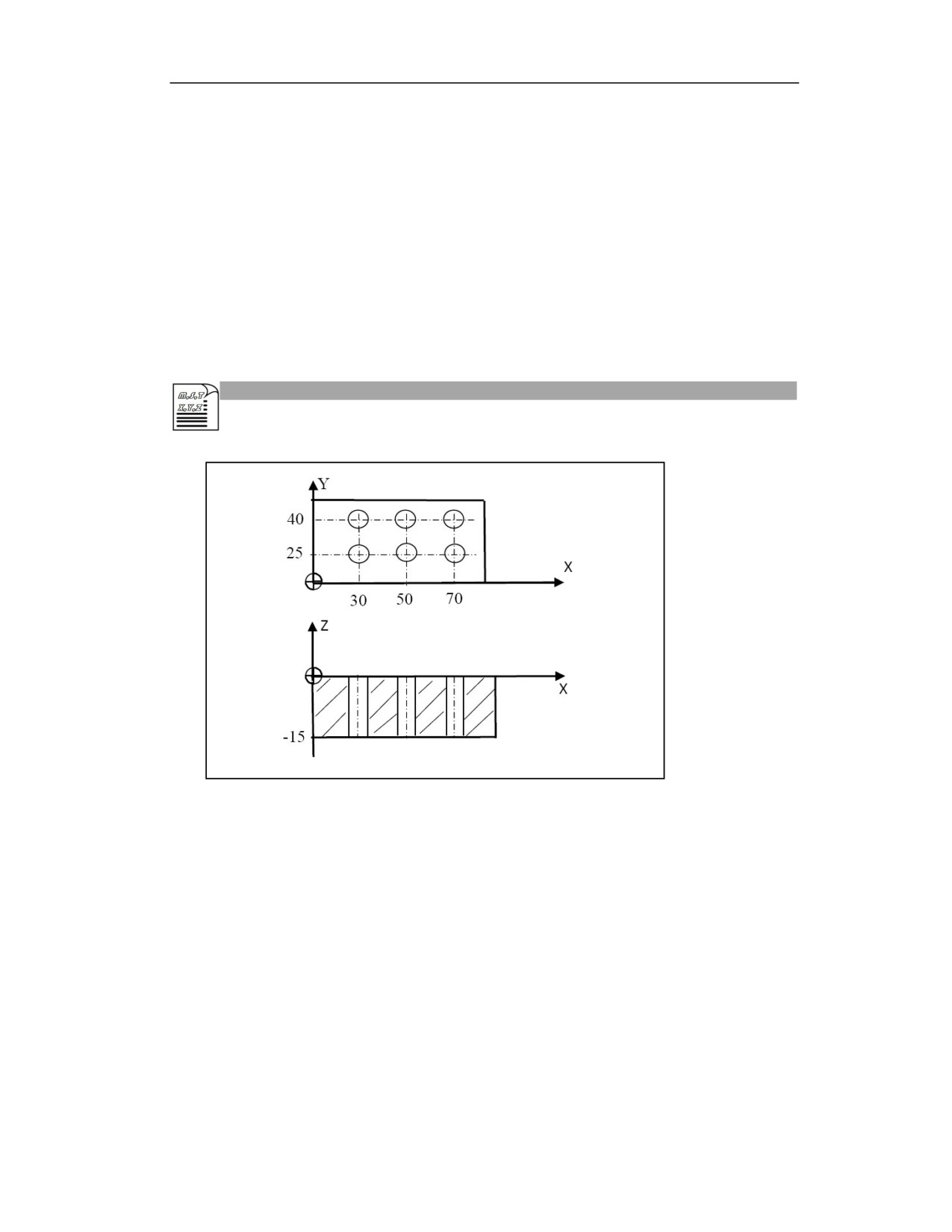
Example
G54G01X0Y0Z50; Safe start point
M3 S1000; Spindle starts rotating
G90 G99 G89 X30 Y25 Z-15 R10 P1000 F120; After positioning, bore hole 1, pause 1
second at hole bottom, return to R point
X50Y25; Bore hole 2, pause 1 second at hole bottom, return to R point
X70Y25; Bore hole 3, pause 1 second at hole bottom, return to R point
X70Y40; Bore hole 4, pause 1 second at hole bottom, return to R point
X50Y40; Bore hole 5, pause 1 second at hole bottom, return to R point
G98 X30Y40; Bore hole 6, pause 1 second at hole bottom, return to initial level
G80 G28 G91 X0 Y0 Z0; Cancel boring, return to reference point
M30; Program end
25
Note
(1) Cancel canned cycle before switching drilling axis.
(2) The drilling axis must be Z axis in G17 plane.
(3) Z point must be lower than R level, otherwise the alarm will be issued.
(4) G89 data is saved as the modal data, and the same data can be omitted.
(5) G89 is similar as G86, and the dwell is performed at hole bottom.
(6) If the moving amount on Z is zero, G89 is not executed.
(7) Use corresponding M code to rotate spindle before using G89.
(8) Drilling is not performed in the blocks that not includes X, Y, Z, R or any other additional axis.
(9) The tool position offset is omitted in the drilling canned cycle mode.
(10) Do not specify the G code (G00-G03) of group 01 in the G89 block; otherwise, G86 will be
cancelled.
15.14
Drilling Canned Cycle Cancel (G80)
Function and Purpose
This command is used to cancel drilling canned cycle
Command Format
G80;
Example
N0 M3 S1000; Spindle starts rotation
N10 G0 Z20; Position to initial level
N20 G90 G99 G81 X30. Y25. Z-2. R5.F120.;Position to hole 1, return to R point
N30 Y50;Position to hole 2, return to R point
N40 Y70;Position to hole 3, return to R point
N50 X100;Position to hole 3, return to R point
N60 Y80;Position to hole 4, return to R point
N70 G98 Y100;Position to hole 6, return to initial level
N70 G80 G28 G91 X0 Y0 Z0;Cancel canned cycle, return to reference point
N80 M5;Spindle stops rotating
N90 M30;Program end
25
Note
(1) After canceling all drilling canned cycles, resume the normal operation;
(2) Cancel R level and Z level;
(3) Other drilling parameter data are also cancelled; after canceling all drilling canned cycles,
normal operation will be resumed;
25

16 Extended Canned Cycle(M)
16.1
Extended Canned Cycle (M)
Function and Purpose
The CNC controller can use extended fixed cycles to process some hole parts with simple contour,
simplifying programming. The extended canned cycles include: engraving canned cycles, drilling
extended cycles, circular pocket cycles, circumferential groove milling cycles, rectangular pocket
cycles, end face milling cycles, rectangular boss cycles, circular boss cycles, etc.
16.2
Engraving Canned Cycle (G1025)
Function and Purpose
In actual processing, after the workpiece is processed, relevant information should be engraved on
the surface of the workpiece, including the workpiece model, machine number, processing time
and date, etc.
The engraving of the specified character information can be realized at the specified position with
this engraving cycle, and the character size and direction can be adjusted.
Command Format
G1025C_ F_ E_ H_ V_ B_ Q_U_W_A_R_O_S_ P=“_”;
Parameter
Meaning
The tool lifting height relative to the engraving level. If this parameter is not defined,
C
it is 10 by default. It is generally a positive value.
The composite feedrate when engraving. If this parameter is not defined, it defaults to
F
1000
The absolute position of center point of the first character in XY direction in absolute
programming (G90)
X_ Y_
The distance from center point of the first character to the starting point in XY
direction in incremental programming (G91)
The absolute position of B point on the engraving level in absolute programming
(G90)
B
The distance from B point on the engraving level to the initial level in Z direction in
incremental programming (G91)
Q
The feed depth relative to the engraving level. It is generally a positive value.
25

The engraved character size (the font height). If this parameter is not defined, the
U
default is 5(mm). It is generally a positive value.
The distance between two characters. If this parameter is not defined, the default is
W
0.8 (mm).It ranges from 0.4 to 2.0. If this range is exceeded, an alarm will be issued.
Character rotation angle. 1: 0°; 2: 90°; 3: 180°; 4: 270°. It cannot be used
A
simultaneously with R. If both A and R are not defined, the rotation angle defaults to
0°.
The rotation angle of the character. Range: -360°≤setting value≤360°. It cannot be
R
used at the same time with A. If A and R are not defined, the rotation angle defaults to
0°.
Date and time type. 1: Month day-hour minute (Example 1214-1328); 2: Month day
(Example 1215) 3: Year month day (Example 151214); 4: Year month day-hour
O
minute (Example 151214-1328). If this parameter is not defined, the default is 1, that
is, month day-hour minute.
To specify the engraving characters in the quotation marks, up to 60 characters. The
currently specified characters are 0 to 9, A to Z, -, ., # (# indicates time and date). For
P=“”
example, P="AB-123" means the engravings of AB-123; P=“N-#-18” means the
engravings of N-1214-1328-18.
S
Spindle speed. If it is not defined, the modal speed value is valid.
Description
Actions
After the positioning on X and Y axes, the tool moves to the center point coordinates (coordinates
HV) of the first character at the G00 speed; meanwhile, the tool positions to the initial level in
rapid traverse;
Move down (C height) on Z axis in rapid traverse,and position to the engraving level B;
Feed (L depth) with G01 for engraving corresponding characters;
After engraving, return to the initial level on Z axis in rapid traverse;
Move one character spacing, and perform the engraving of the second character according to the
above actions until all the specified characters have been engraved;
Actions
25
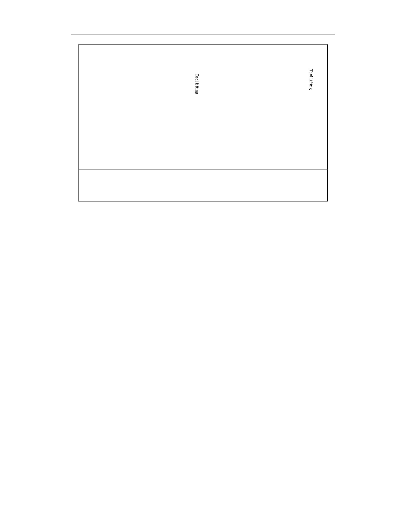
Center coordinate (H V) of the first character
Center coordinate (H V) of the first character
Initial level
Initial level
Tool lifting height
Tool lifting height
B point, engraving
B point,
N character spacing
level
engraving level
Feed depth L
Feed depth L
The first character
The Nth character
B point: engraving level
C line segment: lifting height C
L line segment: engraving depth L
Tool length compensation
When the tool length compensation (G43, G44, G49) is specified in engraving canned cycle, this
compensation should be used at the time of positioning to B point.
Spindle rotation
Use the auxiliary function (M code) to rotate spindle before G1025 is specified, and specify the
spindle speed cyclically. If it is not defined, the modal speed value is valid.
Command use
Engraving cycle program import
For the existing system needing to be upgraded to V1.25.00 and above, export USERDEF.CYC
user-defined canned cycle through data management, copy the provided G1025 cycle program to
USERDEF.CYC, and then reload USERDEF.CYC to the system. Then it can be used after power
off and restart.
Alarms for parameters of engraving cycle
All parameters in the engraving cycle are non-modal, and each parameter needs to be defined
when it is called multiple times.
The parameter value that must be defined
The center position of the first character X and Y must be defined, the engraving level B must be
defined, and the engraving depth Q must be defined:
If the X parameter value is not defined, the alarm will prompt "Engraving cycle-X axis positioning
coordinate X is not set"
25
If the Y parameter value is not defined, the alarm will prompt "Engraving cycle-Y axis positioning
coordinate Y is not set".
If the value of B parameter is not defined, the alarm will prompt "Engraving cycle- engraving
level B is not defined".
If the Q parameter value is not defined, the alarm will prompt "Engraving cycle-engraving depth
Q is not defined".
Default W parameter value
If the character spacing W is defined, the default spacing between characters is 0.8mm, and the
value of W ranges from 0.4 to 2.0. If the input number is not within the range, the alarm will
prompt "Engraving cycle-character spacing exceeds the set range" .
A parameter value
Rotation angle A needs to be set to 1, 2, 3, 4. If it is set to other values, an alarm will prompt
"Engraving cycle-Rotation angle setting error".
Note: Rotation angle parameters A and M cannot be set at the same time. If A and M are set at the
same time, an alarm will be shown "Engraving cycle-A and M cannot be used at the same time to
set the rotation angle"
M parameter value
The value of any rotation angle setting parameter M must be less than 360 and greater than -360.
If it is set to a value larger than 360 or less than -360, an alarm will be displayed "Engraving cycle-
rotation angle setting error".
Note: Rotation angle parameters A and M cannot be set at the same time. If A and M are set at the
same time, an alarm will be shown "Engraving cycle-A and M cannot be used at the same time to
set the rotation angle"
Q parameter value
The date and time type setting parameter O needs to be set to 1, 2, 3, and 4, and if it is set to other
values, an alarm will be displayed "Engraving cycle-date and time type O setting error.
P parameter value
The engraving characters in P="_" can only be the provided characters, including 0 to 9, A to Z,
-,., # (# indicates the time and date). If other characters are specified, such as *, an alarm will be
displayed "Engraving cycle-the specified characters are not recognized".
Example
Example 1
%1234
G54G01X20Y20
G0Z30
25
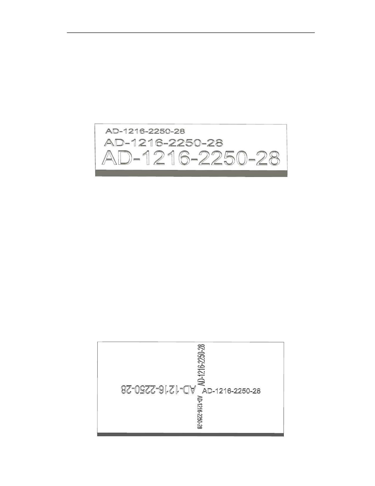
G1025 A1 C10 F200 E800 H25.0 V50.0 B2.0 Q3.0 U2 O1 S1000 P="AD-#-28"
G90G0Z30
G1025 A1 C10 F200 E800 H25.0 V45.0 B2.0 Q3.0 U5 S1000 P="AD-#-28"
G90G0Z30
G1025 A1 C10 F200 E800 H25.0 V35.0 B2.0 Q3.0 U10 S1000 P="AD-#-28"
M30
The interpolation trajectory is shown in the figure below,
Example 2
%1234
G54G01X20Y20
G0Z30
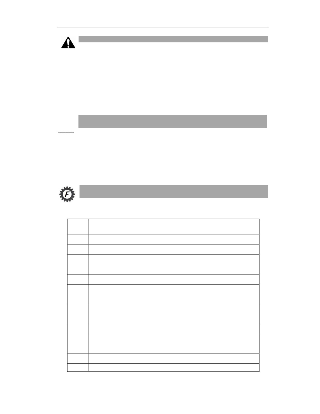
G1025 A1 C10 F800 E800 H25.0 V45.0 B2.0 Q3.0 U5 O1 S1000 P="AD-#-28"
G90G0Z30
G1025 A2 C10 F800 E800 H20.0 V55.0 B2.0 Q3.0 U5 O1S1000 P="AD-#-28"
G90G0Z30
G1025 A3 C10 F800 E800 H15.0 V45.0 B2.0 Q3.0 U10 O1S1000 P="AD-#-28"
G90G0Z30
G1025 A4 C10 F800 E800 H20.0 V35.0 B2.0 Q3.0 U3 O1 S1000 P="AD-#-28"
M30
The interpolation trajectory is shown in the figure below,
25
Note
The engraving cycle can realize the engraving of characters 0 to 9, A to Z, -, . , and time and date
(# indicates time and date). The character font format is Arial, with the default font height 5mm
and the character width 3.09mm (character height*0.618). The default character spacing is 0.4mm,
and the total number of characters for a single engraving does not exceed 60.
16.3
Drilling Type
16.3.1 Circumferential Hole Drilling Cycle (G70)
Function and Purpose
On the circle centered on the coordinate (X,Y) with radius I, start from the point formed by the X
axis and the angle J, divide the circle into N equal parts, and perform the drilling of N holes.
Based on the values of Q and K, the G81 or G83 standard canned cycle is executed for the drilling
of each hole. The position movement between holes is carried out in G00 mode.
G70 is a modal command, and the following command word is non-modal.
vCommand Format
(G98/ G99) G70 X_ Y_ Z_ R_ I_ J_ N_ [Q_K_P_] F_ L_;
Param
Meaning
eter
X、Y
Coordinates of circle center
Z
Coordinates of hole bottom
Coordinates of R point in absolute programming; distance from intial point B to R
R
point in incremental programming.
I
Radius of circle
Angle of initial drilling point, the positive value indicates the counterclockwise
J
direction
Number of holes, the positive value indicates the drilling in counterclockwise
N
direction, and the negative value indicates the drilling in clockwise direction;
Q
Feed depth, directed distance
K
Each time the tool is retracted and fed again, the distance from the last machined
surface when the rapid traverse feed is converted to the cutting feed
P
Dwell time at hole bottom, unit: ms
F
Cutting feedrate
25
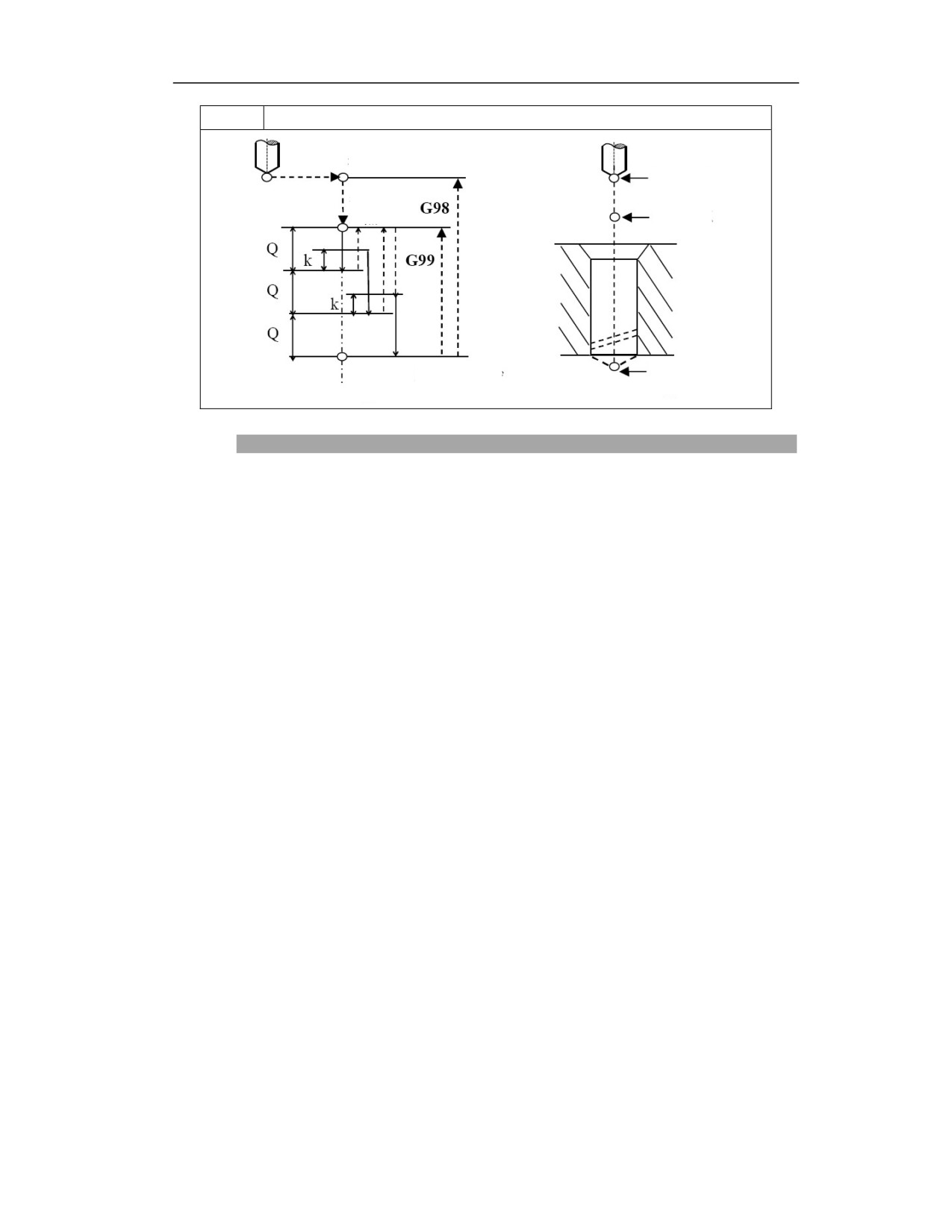
L
Number of cycles (can be omitted when L=1)
Initial point R
Initial point R
Reference
point R
Reference
point R
Delay P ms at
Hole bottom
Hole bottom
hole bottom
Z point
Z point
Description
Action
(1) After positioning along X axis and Y axis with drilling angle, the tool quickly moves to point
B above the hole center;
(2) Move close to the workpiece surface in rapid traverse, reach to R point;
(3) Drilling downward at F speed;
(4) Reach to hole bottom Z point;
(5) Dwell P ms at hole bottom (spindle keeps rotating);
(6) Retract upward to R point (G99) or B point (G98) in rapid traverse;
(7) Spindle keeps rotating;
(8) Program end.
Spindle rotation
Rotate spindle with auxiliary function (M code) before using G70.
When continuously performing drilling of a short distance from the hole position and the initial
level to the R point level, the spindle may not be able to rotate normally before entering the hole
cutting. In this case, do not specify the number of repetitions L, and user needs to insert the GO4-
based pause before each drilling action to take some time out.
Tool length compensation
When the tool length compensation (G43, G44, G49) is specified in drilling canned cycle, this
compensation should be used at the time of positioning to R point.
Auxiliary function
26
When G70 command and M code are specified in the same block, the M code is executed during
the initial positioning. When the number of repetitions L is specified, the above actions will be
executed only for the first time, and M codes will not be executed after the second time.
Example
Example 1: To drill four holes in the four axis directions in the XY plane. This cycle is executed
twice and the G81 drilling is executed at the bottom of the hole.
G98 G70 X10 Y10 Z0 R20 I10 J0 N4 F200 L2
Example 2: To drill four holes at 45 degrees in the XY plane. This cycle is executed once and the
G81 drilling is executed at the bottom of the hole.
G99 G70 X10 Y10 Z10 R50 I10 J45 N-4 F200
Example 3: To drill four holes at -45 degrees in the XY plane. This cycle is executed once and
the G81 drilling is executed at the bottom of the hole.
G99 G70 X10 Y10 Z10 R50 I10 J-45 N-4 F200
Example 4: To drill four holes at -45 degrees in the XY plane. This cycle is executed once, the
G81 drilling is executed at the bottom of the hole, and the Q value is invalid.
G99 G70 X10 Y10 Z10 R50 I10 J-45 N-4 Q-10 F200
26
华中 8 型数控系统编程说明书
Example 5: To drill four holes at -45 degrees in the XY plane. This cycle is executed once, and
the G81 drilling is executed at the bottom of the hole.
G99 G70 X10Y10Z10R50 I10J-45N-4 Q0 F200
G99 G70 X10Y10Z10R50 I10J-45N-4 K0 F200
G99 G70 X10Y10Z10R50 I10J-45N-4 Q0K0 F200
Example 6: To drill four holes at -45 degrees in the XY plane. This cycle is executed once, and
the G83 drilling is executed.
G99 G70 X10Y10Z10R50 I10J-45N-4 Q-10 K5 F200
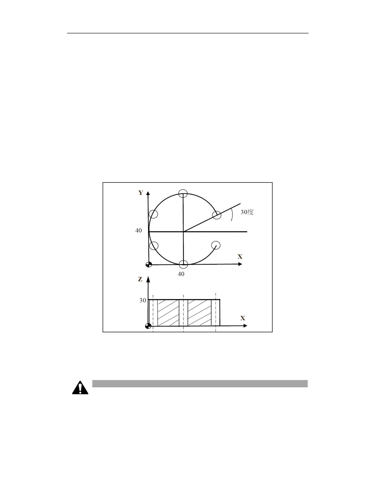
Example: Use a Φ10 drill to process the hole shown in the figure:
N10 G55 G00 X0 Y0 Z80
N20 G98G70G90X40Y40R35Z0I40J30N6P2000-10K5F100
N30 G90 G00 X0 Y0 Z80
N40 M30
Note
(1) Cancel canned cycle before switching drilling axis.
(2) The drilling axis must be Z axis in G17 plane.
(3) If the moving position is zero on Z, this command will not be executed.
26
华中 8 型数控系统编程说明书
(4) Z point must be higher than R level, otherwise the alarm will be issued.
(5) I cannot be omitted; otherwise the alarm will be issued.
(6) G70 data is saved as the modal data, and the same data can be omitted.
(7) Use the corresponding M code to rotate spindle before using G70.
(8) Drilling is not performed in the blocks that not include X, Y, Z, R or any other additional
axis.
(9) When Q is larger than zero or K is smaller than zero, the system reports errors; when Q or
K is zero or is not defined, the G81 center drilling cycle is execute for each hole, and P is invalid;
when values of Q and K are correct, the G83 deep hole drilling cycle is executed fro each hole,
and P is valid.
(10) The tool position offset is omitted in the drilling canned cycle mode.
(11) Do not specify the G code (G00-G03) of group 01 in the G70 block; otherwise, G70 will
be cancelled.
(12) When the angle is defaulted, the angel value =360/n.
16.3.2 Circular Hole Drilling Cycle (G71)
Function and Purpose
On the arc centered by the coordinates (X, Y) with radius I, start from the point formed by the
X axis and the angle J, and drill N holes at an interval of O angle. The G81 or G83 standard
canned cycle is executed based on the Q and K values for each hole. The movement of the
positions between holes is carried out in G00 mode. G71 is a modal command, and the
following command word is non-modal.
Command Format
(G98/G99) G71 X_ Y_ Z_ R_ I_ J_ N_O_ [Q_K_P_] F_ L_;
Parameter
Meaning
Z
Coordinates of hole bottom
Coordinates of R point in absolute programming; distance from initial point B to R
R
point in incremental programming
X,Y
Coordinates of acr center
I
Radius
Angle of initial drilling point, the positive value indicates the counterclockwise
J
direction
Angle between holes. The positive value indicates the drilling in counterclockwise
O
direction, and the negative value indicates the drilling in clockwise direction
N
Number of holes including the starting point
26

华中 8 型数控系统编程说明书
Q
Feed depth, directed distance
K
Each time the tool is retracted and fed again, the distance from the last machined
surface when the rapid traverse feed is converted to the cutting feed
P
Dwell time at hole bottom, unit: ms
F
Cutting feedrate
L
Number of cycles (can be omitted when L=1)
Description
Actions
(1) After positioning along X axis and Y axis with the drilling angle, the tool position moves to
point B above the hole center;
(2) Move close to the workpiece surface in rapid traverse, reach to R point;
(3) Drilling downward at F speed;
(4) Reach to the hole bottom Z point;
(5) Dwell P ms at hole bottom (spindle keeps rotating);
(6) Retract upward to R point (G99) or B point (G98) in rapid traverse;
(7) Spindle keeps rotating;
(8) Program end.
Spindle rotation
Rotate spindle with auxiliary function (M code) before using G71.
When continuously performing drilling of a short distance from the hole position and the initial
level to the R point level, the spindle may not be able to rotate normally before entering the hole
cutting. In this case, do not specify the number of repetitions L, and user needs to insert GO4-
based pause before each drilling action to take some time out.
Do not need to consider the above situation for some machine tools.Please refer to the manual
provided by the machine tool manufacturer.
Tool length compensation
When the tool length compensation (G43, G44, G49) is specified in drilling canned cycle, this
compensation should be used at the time of positioning to R point.
Auxiliary function
When G71 command and M code are specified in the same block, the M code is executed during
the initial positioning. When the number of repetitions L is specified, the above actions will be
26
华中 8 型数控系统编程说明书
executed only for the first time, and M codes will not be executed after the second time.
Example
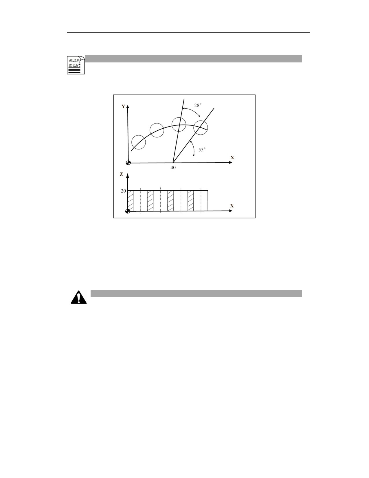
Use Φ10 drill bit to process the hole as shown,
%3359
N10 G55 G00 X0 Y0 Z80
N20 G98G71G90X40Y0G90R25Z0I40J55O28N4P2000-10K5F100
N30 G90 G00 X0 Y0 Z80
N40 M30
Note
(1) When Q is larger than zero or K is smaller than zero, the system reports errors; when Q or
K is zero or is not defined, the G81 center drilling cycle is executed for each hole, and P is
invalid; when values of Q and K are correct, the G83 deep hole drilling cycle is executed fro
each hole, and P is valid.
(2) The total arc angle N×O cannot be greater than or equal to 360 degrees, otherwise it will
not be executed;
(3) Cancel canned cycle before switching drilling axis.
(4) The drilling axis must be Z axis in G17 plane.
(5) If the moving amount is zero on Z, this command will not be executed.
(6) Z point must be higher than R level, otherwise the alarm will be issued.
(7) The values of I and O cannot be omitted, otherwise the alarm will be issued.
26
华中 8 型数控系统编程说明书
(8) G71 data is saved as the modal data, and the same data can be omitted.
(9) Use corresponding M code to rotate spindle before using G71.
(10) Drilling is not performed in the blocks that not include X, Y, Z, R or any other additional
axis.
(11) The tool position offset is omitted in the drilling canned cycle mode.
(12) Do not specify the G code (G00-G03) of group 01 in the G71 block; otherwise, G71 will
be cancelled.
16.3.3 Straight Line Hole Cycle (G78)
Function and Purpose
The cycle starts with the position (X, Y), and drill N holes in the direction formed by the X axis
and J angle with the interval I. The G81 or G83 canned cycle is performed for each hole based
on the value of Q and K. The movement between the holes is carried out in G00 mode. G78 is
a modal command, and the following command word is non-modal.
Command Format
(G98/G99)G78 X_Y_Z_R_I_J_N_[Q_K_P]_F_L_;
Parameter
Meaning
X Y
Coordinates of the first hole
Coordinates of hole bottom. Coordinates of R point in absolute programming; distance
Z
from intial point B to R point in incremental programming
I
Distance between holes
The starting angle formed by the straight line and the positive direction of X-axis, the
J
positive value indicates the counterclockwise direction;
N
Number of holes including the starting point
Q
Feed depth, directed distance
K
Each time the tool is retracted and fed again, the distance from the last machined surface
when the rapid traverse feed is converted to the cutting feed
P
Dwell time at hole bottom, unit: ms
Description
Action
(1)After positioning along X axis and Y axis with drilling angle, the tool position quickly
moves to point B above the hole center;
(2)Move close to the workpiece surface in rapid traverse, reach to R point;
26
华中 8 型数控系统编程说明书
(3)Drill downward at F speed;
(4)Reach to hole bottom Z point;
(5)Dwell P ms at hole bottom (spindle keeps rotating);
(6)Retract upward to R point (G99) or B point (G98) in rapid traverse;
(7)Spindle keeps rotating;
(8)Program end with M30.
Spindle rotation
Rotate spindle with auxiliary function (M code) before using G78.
When continuously performing drilling of a short distance from the hole position and the initial
level to the R point level, the spindle may not be able to rotate normally before entering the
hole cutting action. In this case, do not specify the number of repetitions L, and user needs to
insert GO4-based pause before each drilling action to take some time out.
Do not need to consider the above situation for some machine tools. Please refer to the manual
provided by the machine tool manufacturer.
Tool length compensation
When the tool length compensation (G43, G44, G49) is specified in drilling canned cycle, this
compensation should be used at the time of positioning to R point.
Auxiliary function
When G78 command and M code are specified in the same block, the M code is executed during
the initial positioning. When the number of repetitions L is specified, the above actions will be
executed only for the first time, and M codes will not be executed after the second time.
Example
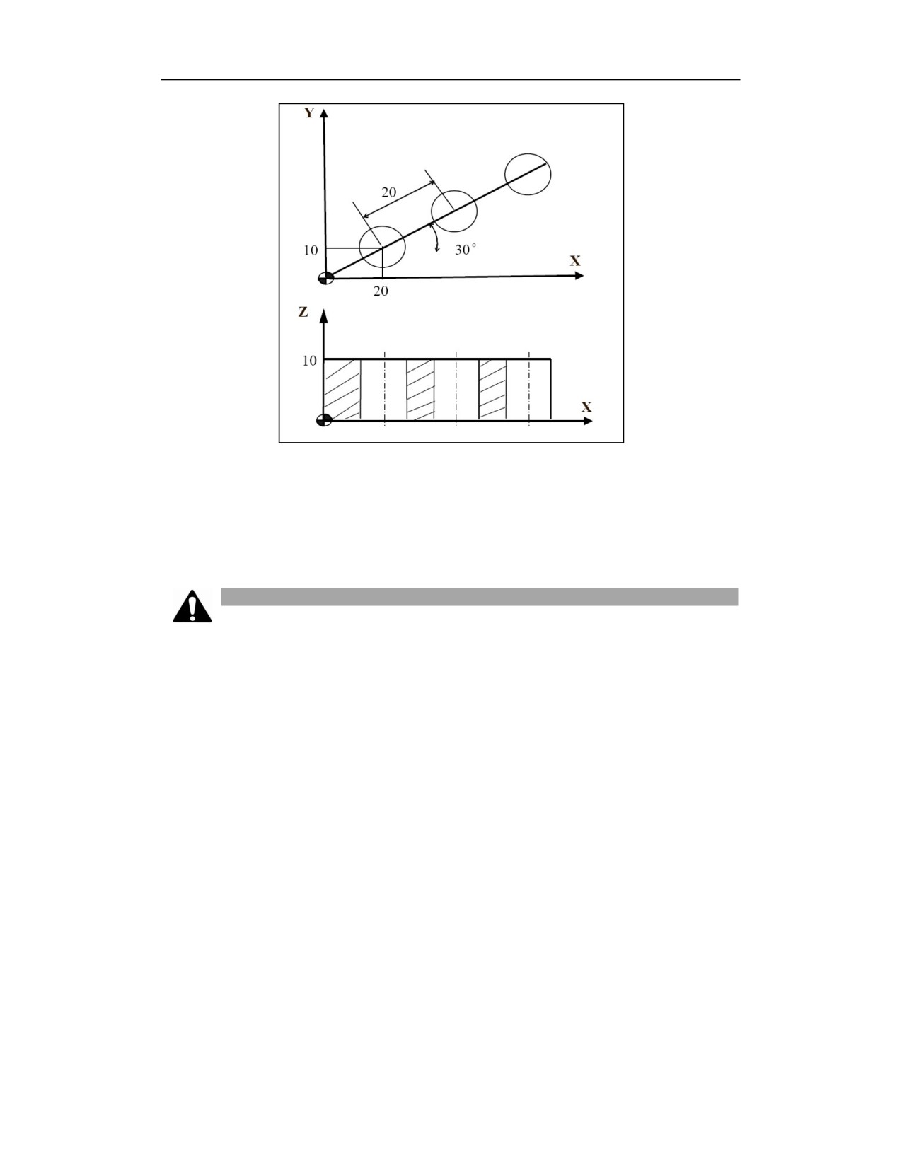
Example: Use a Φ10 drill to process the hole shown in the figure.
26
华中 8 型数控系统编程说明书
%3360
N10 G55 G00 X0 Y0 Z80
N20 G98G78G90X20Y10G90R15Z0I20J30N3P2000-10K5F100
N30 G90 G00 X0 Y0 Z80
N40 M30
Note
(1) Cancel canned cycle before switching drilling axis.
(2) The drilling axis must be Z axis in G17 plane.
(3) If the moving amount is zero on Z, this command will not be executed.
(4) The Z point must be higher than R level, otherwise the alarm will be issued.
(5) The I value cannot be omitted, otherwise the alarm will be issued.
(6) G78 data is saved as the modal data, and the same data can be omitted.
(7) Use corresponding M code to rotate spindle before using G78.
(8) Drilling is not performed in the blocks that not include X, Y, Z, R or any other additional
axis.
(9) An error is reported when Q is greater than zero or K is smaller than zero; an error is reported
when the feed distance Q is smaller than the retract distance K; when Q or K is zero or is not
defined, the G81 center drilling cycle is executed for each hole, at this time P is invalid; when
the values of Q and K are both correct, G83 deep hole cycle is executed for each hole, and P is
valid at this time.
(10) The tool position offset is omitted in the drilling canned cycle mode.
26
华中 8 型数控系统编程说明书
(11) Do not specify the G code (G00-G03) of group 01 in the G78 block; otherwise, G78 will
be cancelled.
16.3.4 Chess Type Hole Cycle (G79)
Function and Purpose
The cycle starts with the position (X, Y), drills N holes in the direction parallel to X axis with the
interval I, and uses the interval J for drilling in the X axis direction, a total of O cycles. G81 or
G83 canned cycle is performed based on the values of Q and K for each hole. The movement
between holes is performed in G00 mode. G79 is modal, and the following command word is non-
modal.
Command Format
(G98/G99)G79 X_Y_Z_R_I_J_N_[Q_K_P]_F_L_
Para
Meaning
meter
X,Y
Coordinates of the first hole
Z
Coordinates of hole bottom
Coordinates of R point in absolute programming; distance from initial point B to R point
R
in incremental programming
Distance between holes on X. The positive value indicates the drilling in the positive
I
direction of X axis, and the negative value indicates the drilling in the negative direction
of X axis.
N
Number of holes including the start point in the direction of X
Distance between holes on Y. The positive value indicates the drilling in the positive
J
direction of Y axis, and the negative value indicates the drilling in the negative direction
of Y axis.
O
Number of holes including the start point in the direction of Y
Q
Feed depth, directed distance
K
Each time the tool is retracted and fed again, the distance from the last machined surface
when the rapid traverse feed is converted to the cutting feed
P
Dwell time at hole bottom, unit: ms
Description
Action
(1) After positioning along X axis and Y axis with the drilling angle, the tool position quickly
26
华中 8 型数控系统编程说明书
moves to point B above the hole center;
(2) Move close to the workpiece surface in rapid traverse, reach to R point;
(3) Drill downward at F speed;
(4) Reach to hole bottom Z point;
(5) Dwell P ms at hole bottom (spindle keeps rotating);
(6) Retract upward to R point (G99) or B point (G98) in rapid traverse;
(7) Spindle keeps rotating;
(8) Program end with M30.
Spindle rotation
Rotate spindle with auxiliary function (M code) before using G79.
When continuously performing drilling of a short distance from the hole position and the initial
level to the R point level, the spindle may not be able to rotate normally before entering the hole
cutting action. In this case, do not specify the number of repetitions N, and user needs to insert
GO4-based pause before each drilling action to take some time out.
It is unnecessary to consider the above situation for some machine tools.Please refer to the manual
provided by the machine tool manufacturer.
Tool length compensation
When the tool length compensation (G43, G44, G49) is specified in drilling canned cycle, this
compensation should be used at the time of positioning to R point.
Auxiliary function
When G79 command and M code are specified in the same block, the M code is executed during
the initial positioning. When the number of repetitions N is specified, the above actions will be
executed only for the first time, and M codes will not be executed after the second time.
Example
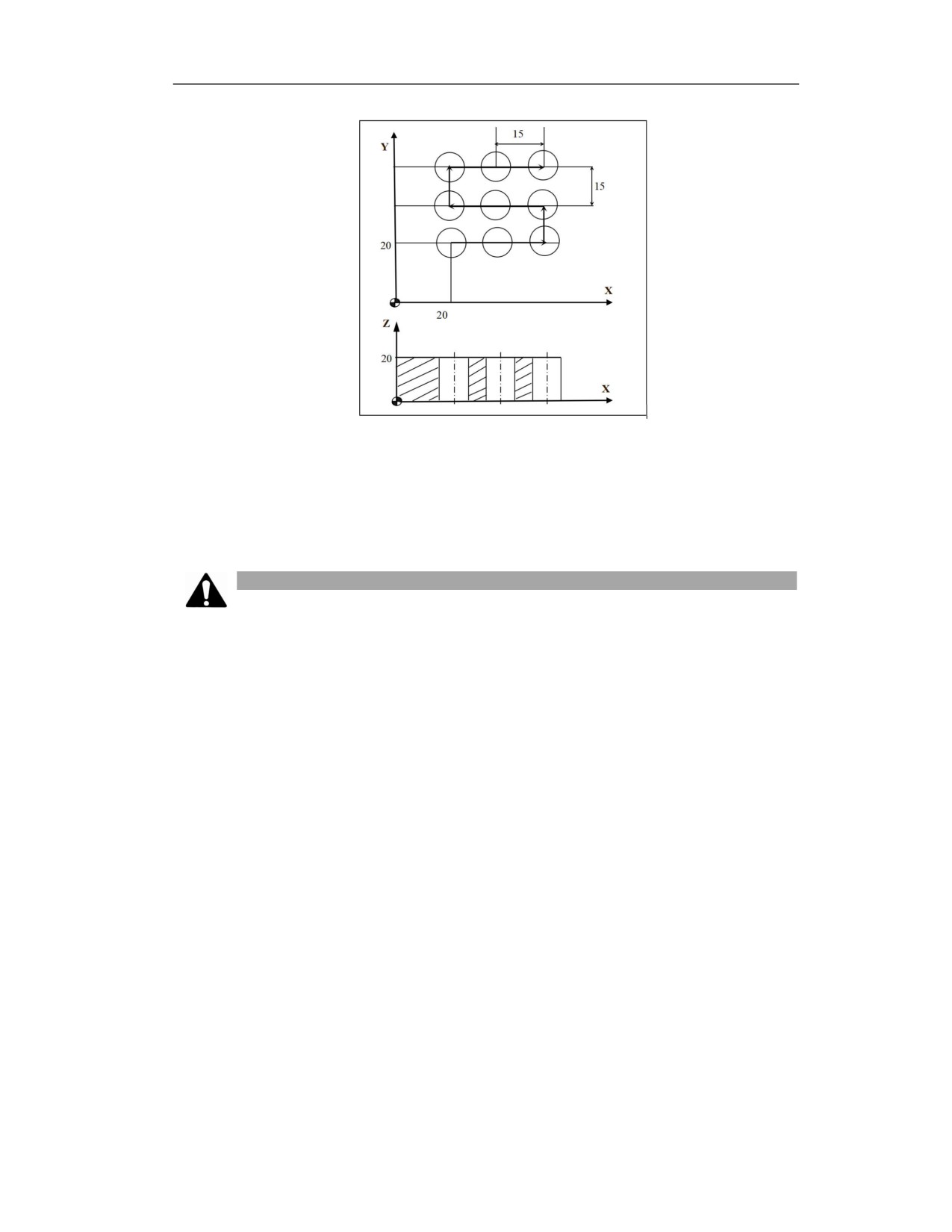
Example: Use a Φ10 drill to process the hole shown in the figure.
27
华中 8 型数控系统编程说明书
%3361
N10 G55 G00 X0 Y0 Z80
N20 G98G79G90X20Y20G90R25Z0I15N3J15O3P2000-10K5F100
N30 G90 G00 X0 Y0 Z80
N40 M30
Note
(1) Cancel canned cycle before switching drilling axis.
(2) The drilling axis must be Z axis in G17 plane.
(3) If the moving amount is zero on Z, this command will not be executed.
(4) Z point must be higher than R level, otherwise the alarm will be issued.
(5) The values of I, O, J cannot be ignored, otherwise the alarm will be issued.
(6) G79 data is saved as the modal data, and the same data can be omitted.
(7) Use corresponding M code to rotate spindle before using G79.
(8) Drilling is not performed in the blocks that not include X, Y, Z, R or any other additional axis.
(9) An error is reported when Q is greater than zero or K is smaller than zero; an error is reported
when the feed distance Q is less than the retract distance K; when Q or K is zero or is not defined,
the G81 center drilling cycle is executed for each hole, at this time P is invalid; when the values
of Q and K are both correct, G83 deep hole cycle is executed for each hole, and P is valid at this
time.
(10) The tool position offset is omitted in the drilling canned cycle mode.
(11) Do not specify the G code (G00-G03) of group 01 in the G79 block; otherwise, G79 will be
cancelled.
27
16.4
Milling Cycle
16.4.1 Circular Groove Milling Cycle (Type 1) (G181)
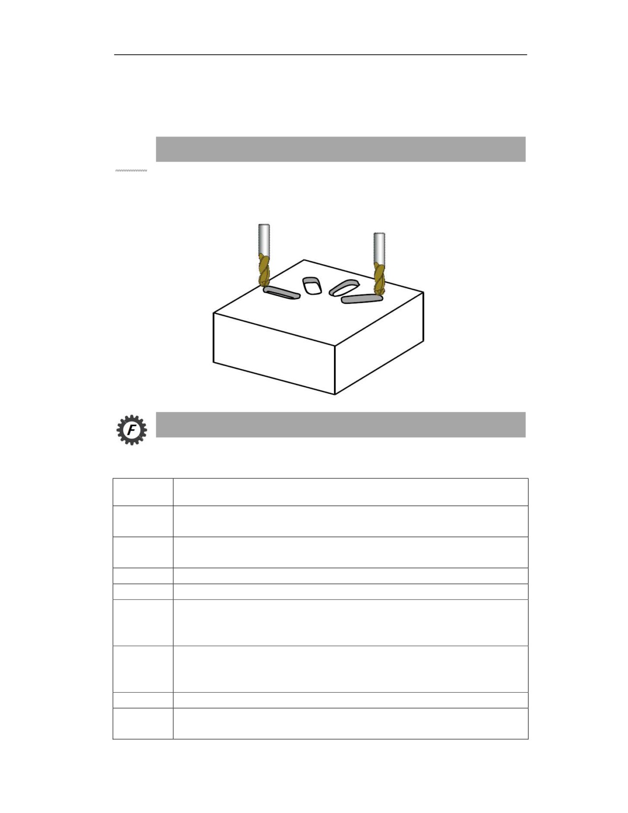
Function and Purpose
This cycle can be used to machine grooves arranged in an arc, and the groove width is determined
by the tool diameter.
Command Format
(G98/G99) G181 R_ Z_ N_ K_ X_ Y_ I_ A_ B_ F_ Q_ V_;
Parameter
Meaning
Coordinates of R point in absolute programming; distance from intial point B to R point
R
in incremental programming
Coordinates of groove bottom in absolute programming; incremental value from groove
Z
bottom to reference point R in incremental programming
N
Number of grooves(can be omitted when L=1)
K
Length of groove
Center position of the arc formed by grooves. Coordinate of the first axis in the current
X
plane in absolute programming; incremental value relative to the starting point in
incremental programming
Center position of the arc formed by grooves. Coordinate of the second axis in the
Y
current plane in absolute programming; incremental value relative to the starting point in
incremental programming
I
Radius of the arc formed by grooves
Starting angle (-180 to 180 degrees. It is a positive value for counterclockwise, and
A
negative value for clockwise, and it can be omitted when A=0)
27
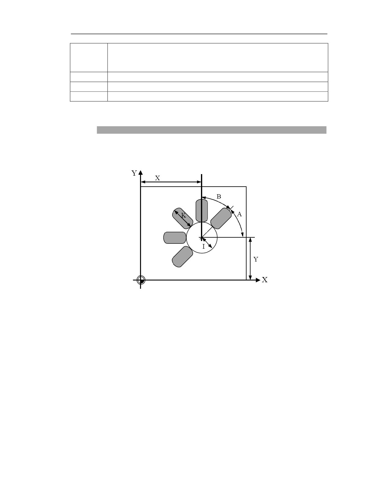
Incremental angle (can be omitted when B=360/N; The negative value indicates the
B
milling of grooves in counterclockwise direction, and the positive value indicates the
milling of grooves in clockwise direction)
F
Milling speed
Q
Max. feed depth (can be omitted when Q=groove depth, one-time cutting to the end)
V
Tool radius
Description
Parameter diagram
Milling steps
(1) Select the initial position to enter the cycle. This point can be any position, but it must be
ensured that every groove can be executed from this point without contour collision;
(2) From the initial position to the reference position R above the near end of the first groove, the
near end refers to the end close to the center of the arc, and the far end is the opposite. The groove
specified by the starting angle parameter A is the first machining groove;
(3) Feed down to the specified depth at the milling speed, and then mill the groove back and forth
to the groove bottom. Each depth feed is performed at the end of the groove;
(4) The application axis (usually the Z axis) retracts to the reference position R. The tool moves
to the end of the next groove along the selected shortest path, and mills back and forth to the
bottom;
(5) After the last groove is machined, retract the tool to the initial position B or reference position
R of the cycle according to the current G98 or G99 modal, and the cycle ends.
27
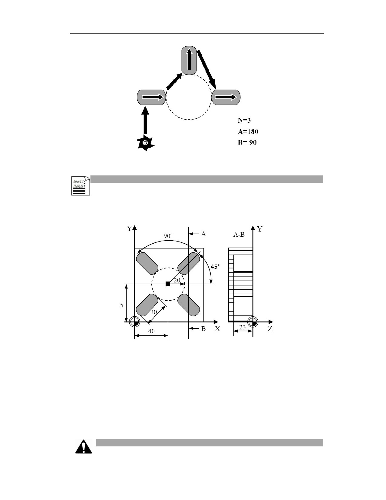
Milling in counterclockwise
direction
Example
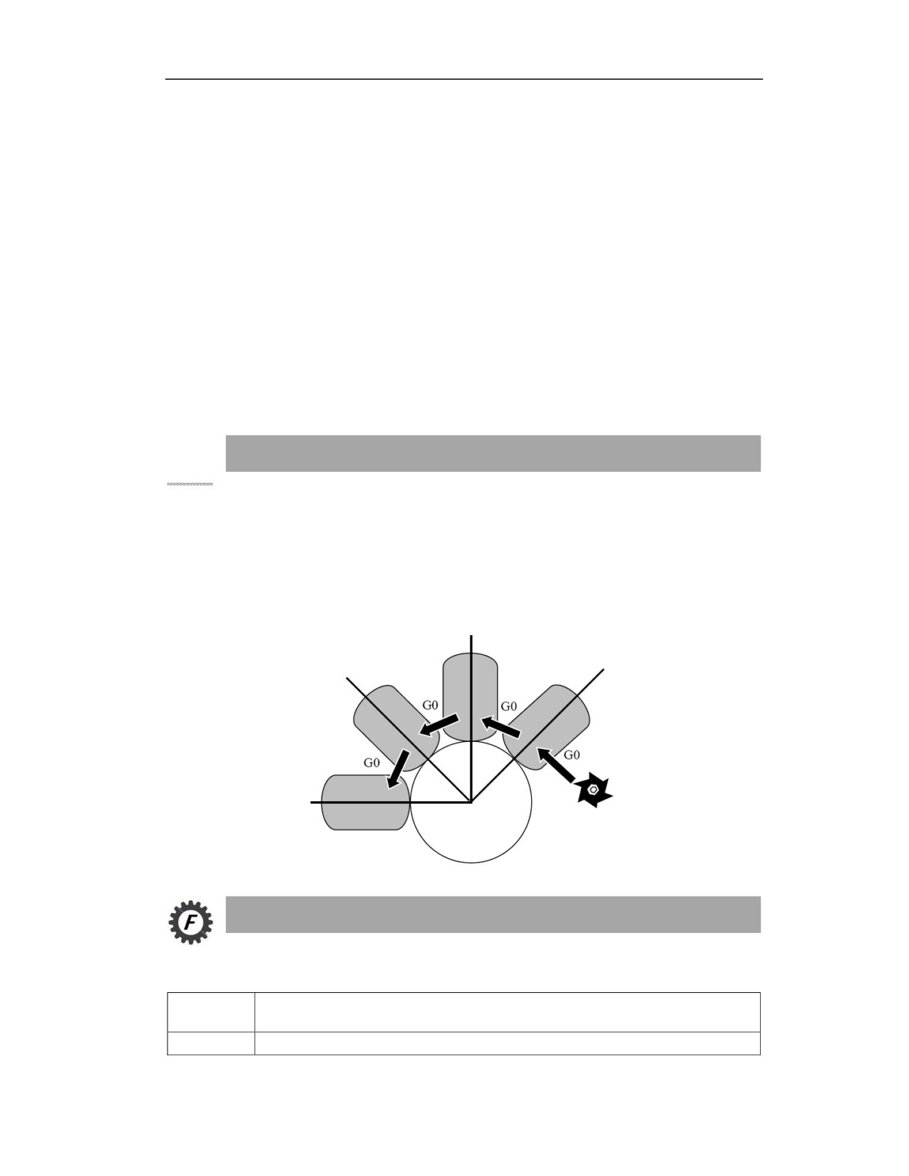
Process 4 rectangular grooves as shown in the figure below, the groove length is 30mm, the groove
depth is 23mm, and the cutting depth is 6mm.
%0526
N10
G54 X0 Y0 Z5
N20
G17 G90
N30
T10
N40
M06
N50
M03 S600
N60
G181 R0 Z-23 N4 K30 X40 Y45 I20 A45 B90 F100 Q6 V5
N70
M30
Note
27
(1) The number of grooves N is input as a non-negative integer, the negative sign is ignored in
the cycle, and the non-integer will be rounded.
(2) The maximum feed depth is specified by Q. If the groove depth cannot be divisible by Q, the
feed depth of the last cut will be less than Q.
(3) The milling direction between the grooves is related to the sign of B. If B is positive, it will
be processed counterclockwise from the first groove to the last groove. If B is negative, the groove
will be processed clockwise. If B is not specified, B=360/N is cycled, and the milling of grooves
is performed counterclockwise.
(4) The input of K, I, and Q are non-negative values. If the input is negative, the negative sign
will be ignored in the cycle;
(5) Rotate the spindle before entering cycle.
16.4.2 Circular Groove Milling Cycle (Type 2) (G182)
Function and Purpose
This cycle can process the grooves arranged in annular. The longitudinal axes of these grooves
are arranged radially. This cycle is different from G181. The groove width can be specified by
parameters instead of the tool diameter.
At the same time, this cycle can specify roughing or finishing.
Command Format
(G98/G99)G182 R_Z_N_K_W_X_Y_I_A_B_F_ Q_ E_O_H_U_P_C_D_V_;
Parameter
Meaning
R
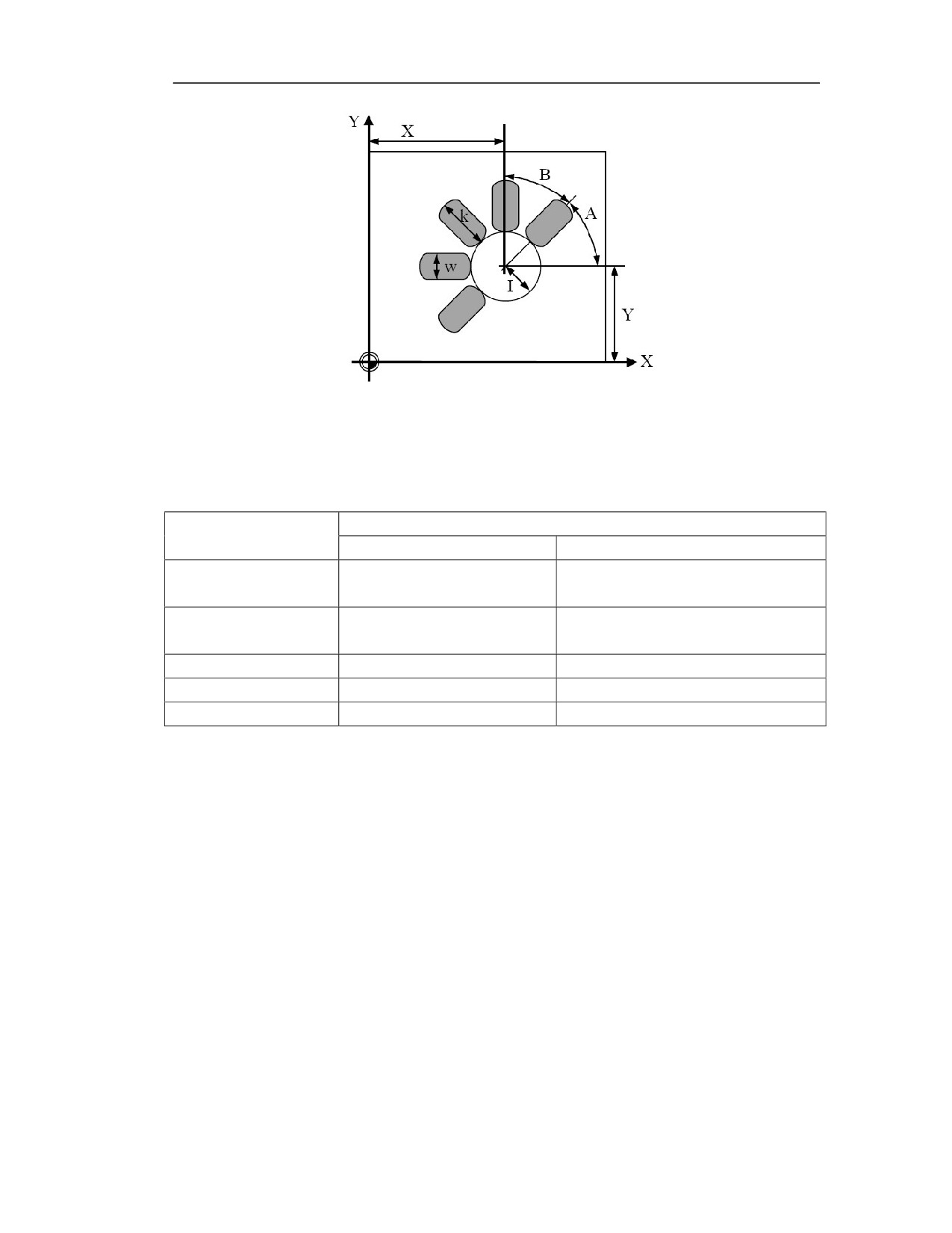
Reference point R coordinates in absolute programming; incremental value of
27
reference point R relative to the initial level.
Coordinate value of groove bottom in absolute programming; incremental value of
Z
groove bottom relative to the reference point R in incremental programming.
N
Number of grooves (can be omitted when N=1)
K
Length of groove
W
Width of groove (can be omitted when W=tool diameter)
Center position of the arc formed by grooves. Coordinate of the first axis in the current
X
plane in absolute programming; incremental value relative to the starting point in
incremental programming
Center position of the arc formed by grooves. Coordinate of the second axis in the
Y
current plane in absolute programming; incremental value relative to the starting point
in incremental programming
I
Radius of the arc formed by grooves
Starting angle (-180 to 180 degrees. It is a positive value for counterclockwise, and
A
negative value for clockwise, and it can be omitted when A=0)
Incremental angle (can be omitted when B=360/N; The negative value indicates the
B
milling of grooves in counterclockwise direction, and the positive value indicates the
milling of grooves in clockwise direction)
F
Milling speed in roughing
Max. feed depth in roughing(can be omitted when Q=groove depth- finishing
Q
allowance of groove bottom)
E
Finishing allowance of groove edge (can be omitted when E=0)
O
Finishing allowance of groove bottom (can be omitted when O=0)
H
Max. feed depth in finishing (can be omitted when H=Q)
U
Feedrate in finishing (can be omitted when U=F)
Spindle speed in finishing (can be omitted when P=spindle speed or default speed
P
before entering cycle)
Milling direction for the groove (can be omitted when C=3)
C
0: milling in the same direction; 1: milling in the reverse direction; 2: milling in the
G02 direction; 3: milling in the G03 direction
Machining type (can be omitted when D=1)
D
1: roughing; 2: finishing
V
Tool radius
Description
Graphical representation
27
Milling direction
The spindle must be specified to rotate before entering the cycle. The cycle calculates a reasonable
milling direction based on the spindle rotation direction M3/4 before the cycle is entered and the
milling direction set by the user. The selection of the milling direction is shown in the following table:
Milling direction
Specify M03 or M04 before entering cycle
(cycle parameter C)
M03 spindle rotation CW
M04 spindle rotation CCW
0:milling in the same
G03
G02
direction
1:milling in the reverse
G02
G03
direction
2:G02 direction
G02
G02
3:G03 direction
G03
G03
Omitted
G03
G03
27
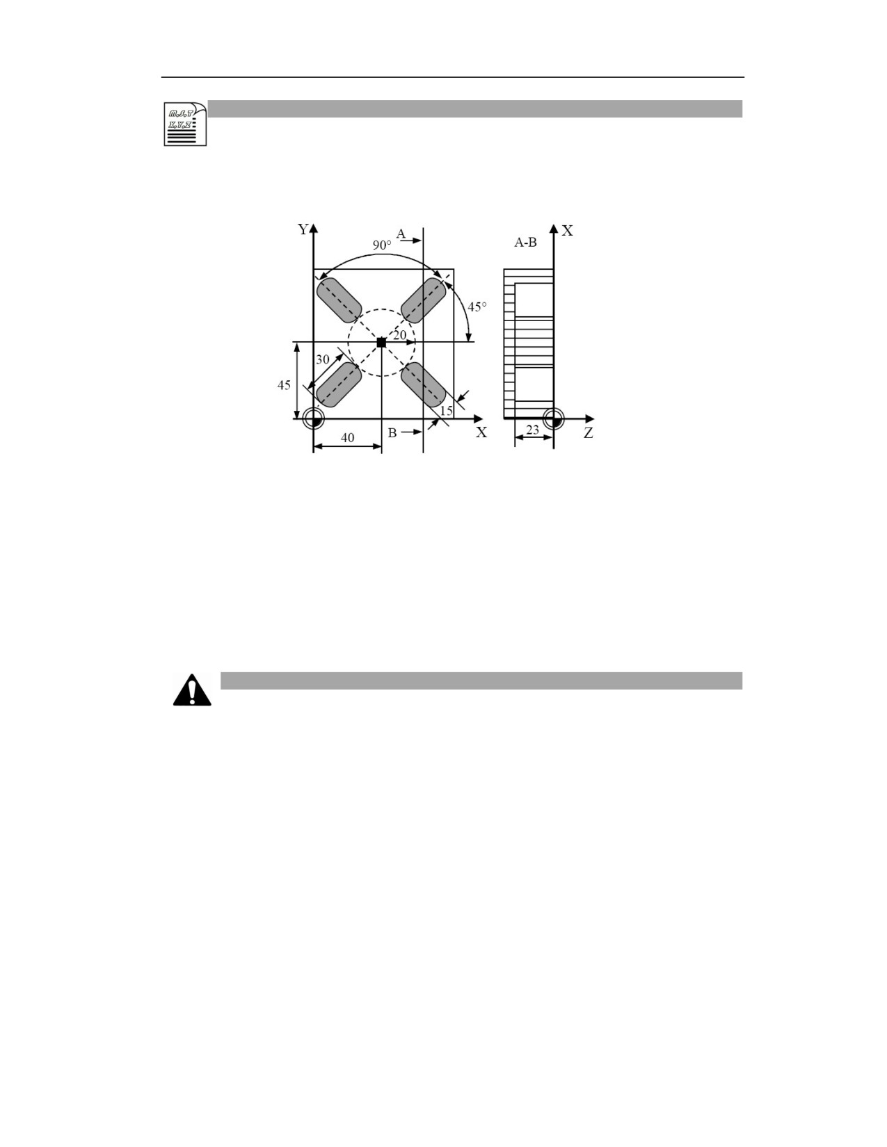
Example
To machine 4 grooves. Groove length 30mm, groove width 15mm, groove depth 23mm, finishing
allowance 0.5mm, milling direction G02, feed depth in roughing 6mm, tool radius 5mm.
%0527
N10 G54 G17 G90
N20 T10
N30 M06
N40 M03 S600
N50 G182R5Z-23N4K30X40Y45W15I20A45B90F100Q6E0.5O0.5C2V5
N60 M30
Note
(1) The tool radius cannot exceed the specified groove width W, otherwise an alarm will be
generated;
(2) The number of grooves N is input as a non-negative integer, the cycle will ignore the negative
sign, and round off the non-integer;
(3) Q and H both refer to the maximum feed depth. Note that when the groove depth cannot be
divisible by feed depth Q or H, the last cut will be less than Q or H;
(4) The milling direction C specifies the milling direction of a single groove, and the angle
increment B specifies the milling direction between the grooves. If B is positive, the processing
will be performed counterclockwise from the first groove to the last groove; and if B is negative,
it will be clockwise. If B is not specified, the cycle will process B=360/N, and the grooves will
be milled counterclockwise;
(5) K, W, I, E, O, Q, H are input as non-negative numbers. If the input is negative, the negative
sign will be ignored in the cycle;
278
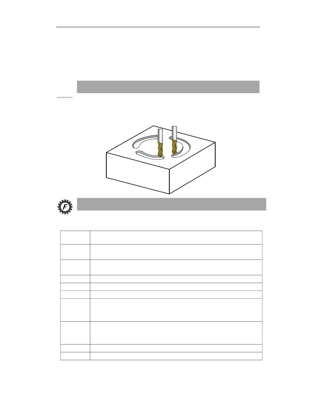
(6) The spindle must be rotated before entering the cycle. In addition, the finishing allowance E
of the specified groove edge cannot exceed the groove width W/2, and the finishing allowance O
of the groove bottom cannot exceed the groove depth, otherwise an alarm will be generated. For
the alarm information, please refer to chapter 16.4.9.
16.4.3 Circumferential Groove Milling Cycle (G183)
Function and Purpose
This cycle can process the grooves distributed on the circle, and can specify rough machining,
finishing or comprehensive machining.
Command Format
(G98/G99)G183R_Z_N_K_W_X_Y_I_A_B_F_ Q_E_O_H_U_P_C_D_V_;
Parameter
Meaning
Coordinates of R point in absolute programming; distance from reference point R to initial level
R
in incremental programming
Coordinate value of groove bottom in absolute programming; incremental value of groove
Z
bottom relative to reference point R in incremental programming.
N
Number of grooves (can be omitted when L=1)
K
Angle of groove length (0 to 360 degrees, unit: degree)
W
Groove width (can be omitted when W=tool diameter)
Center position of the arc formed by grooves. Coordinate of the first axis in the current plane in
X
absolute programming; incremental value relative to the starting point in incremental
programming.
Center position of the arc formed by grooves. Coordinate of the second axis in the current plane
Y
in absolute programming; incremental value relative to the starting point in incremental
programming.
I
Radius of circle arranged by grooves
A
Starting angle (-180 to 180 degress, positive for counterclockwise, and negative for clockwise. It
279