HNC8 Series CNC Controller. Programming Manual (V2.4) - page 6
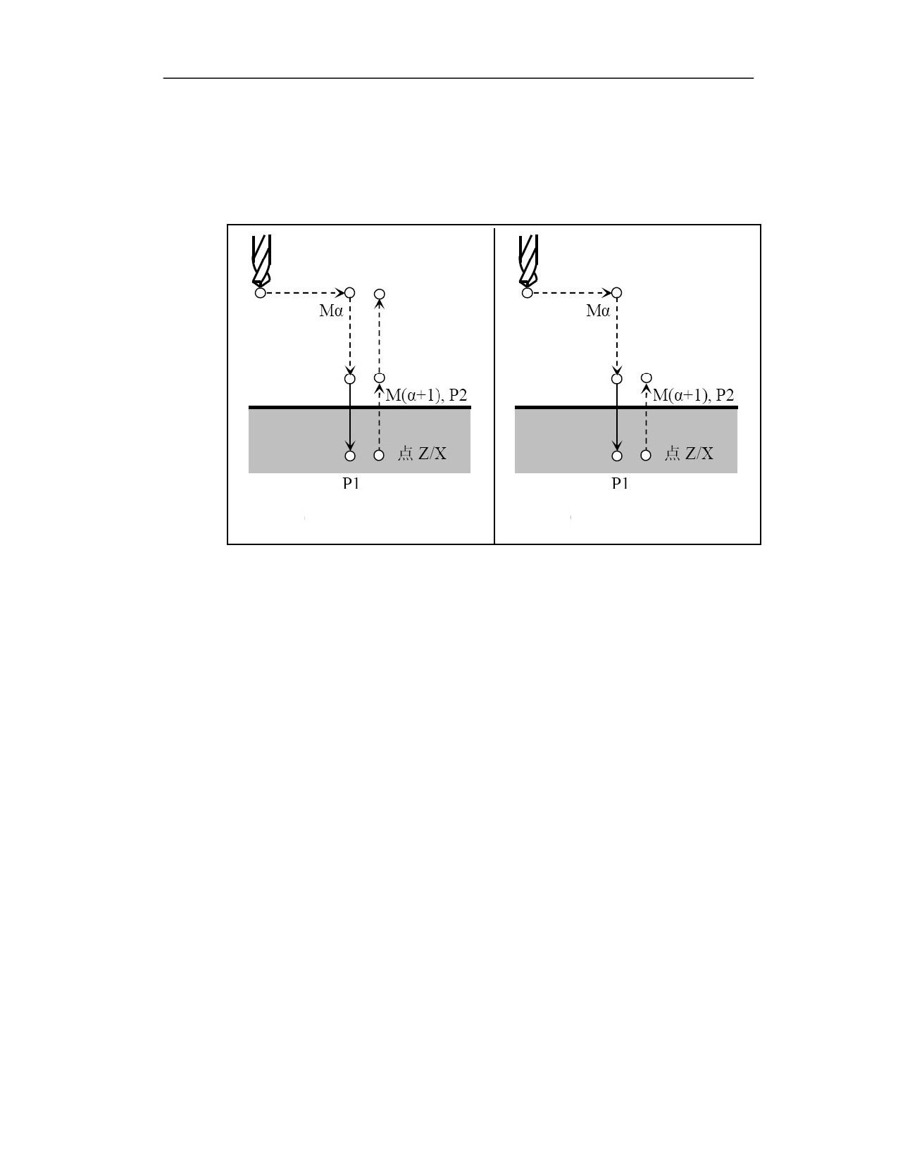
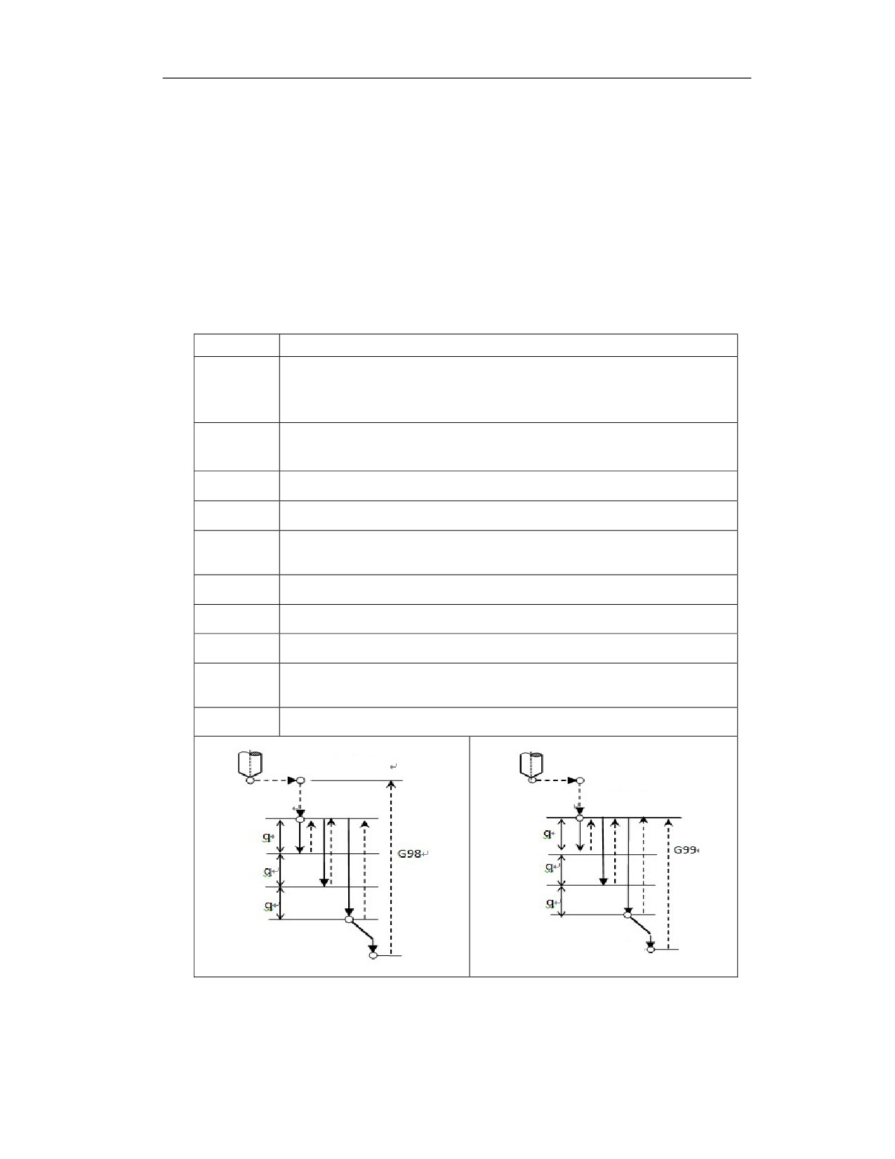
Deep hole processing can be realized through repeated advance and retreat;
After each drilling, the tool exits the workpiece to the safety level R point, which
has a good chip removal effect, and the chip breaking can be achieved.
Spot drilling - H3 mode
Initial level
Point R level
Point R level
G83 or G87 (G98)
G83 or G87 (G99)
Drill directly to the bottom of the hole each time, and then quickly exit;
Designed for shallow hole drilling, no chip breaking and chip removal.
20

Example
To process the workpiece as shown in the diagram, the code format is as follows:
%1111
G54X0Z50
G98G83Z-10R10Q5K2P1000F200H1
G99G83Z-10R10Q5K2P1000F200H1
G0X0Z50
G98G83Z-10R10Q5K2P1000F200H2
G99G83Z-10R10Q5K2P1000F200H2
G0X0Z50
G98G83Z-10R10Q5K2P1000F200H3
G99G83Z-10R10Q5K2P1000F200H3
M30
%1111
G54Z0X50
G98G87X-10R10Q5K2P1000F200H1
G99G87X-10R10Q5K2P1000F200H1
G0Z0X50
G98G87X-10R10Q5K2P1000F200H2
G99G87X-10R10Q5K2P1000F200H2
G0Z0X50
G98G87X-10R10Q5K2P1000F200H3
G99G87X-10R10Q5K2P1000F200H3
M30
Note
(1) When H=1, the tool retracts the specified retraction distance K. It is stipulated in the canned
cycle that when drilling with H1 and H2 modes, the amount of feed Q and the amount of retract
k must be specified.
20
(2) Even if P, Q, K are not specified, if P, Q, K, are specified with previous G83, the variable will
still be inherited. If a G83 line is normally specified, for the following G83 only the coordinates
need to be specified. However, G01 , G00 will terminate this G83 modal, and for G83 after G01,
G00, G02, G03 commands all parameter must be specified.
(3) The feed amount and the retraction amount must be larger than 0.
(4) If PWM spindle is used, C command cannot be used.
14.2.2 Axial Rigid Tapping Cycle (G84)/ Radial Rigid Tapping Cycle (G88)
Function and Purpose
Turning centers with powered tool often require axial or radial thread processing. The G84
command of this system can be used for tapping of axial thread; G87 can be used for tapping of
radial thread. For the two processing methods, there only is the difference in the feed axis, and
the drilling trajectory is exactly the same. The axial tapping is fed along Z axis and the radial
tapping is fed along X axis.
In addition, axial tapping is also suitable for conventional lathes. At this time, the workpiece or
tap can be installed on the lathe spindle to form the main cutting movement, and the tap or
workpiece can be installed on the tool post to perform the Z-axis feed movement to realize the
axial tapping.
Command Format
1. Axial rigid tapping cycle
G84 Z(W)_R_P_Q_E_J_K_F_H_
Parameter
Meaning
Z
Coordinates of hole bottom
R
Distance from initial level to R level
P
Dwell time at hole bottom
F
Feedrate
Q
Feed amount
K
Retraction amount
E1
Forward tapping
E2
Reverse tapping
J1
Tapping of the first spindle C axis
J2
Tapping of the second spindle A axis
H1
Retract the specified retraction amount K
H2
Retract to R point
H3
Directly move to hole bottom
20
2. Radial rigid tapping cycle
G88X(U)_R_E_Q_K_H_P_F_ (Only tapping of the second spindle A axis)
Parameter
Meaning
E1
Forward tapping
E2
Reverse tapping
Q
Feed amount
K
Retraction amount
H1
Retract the specified retraction amount K
H2
Retract to R point
H3
Directly move to hole bottom
Description
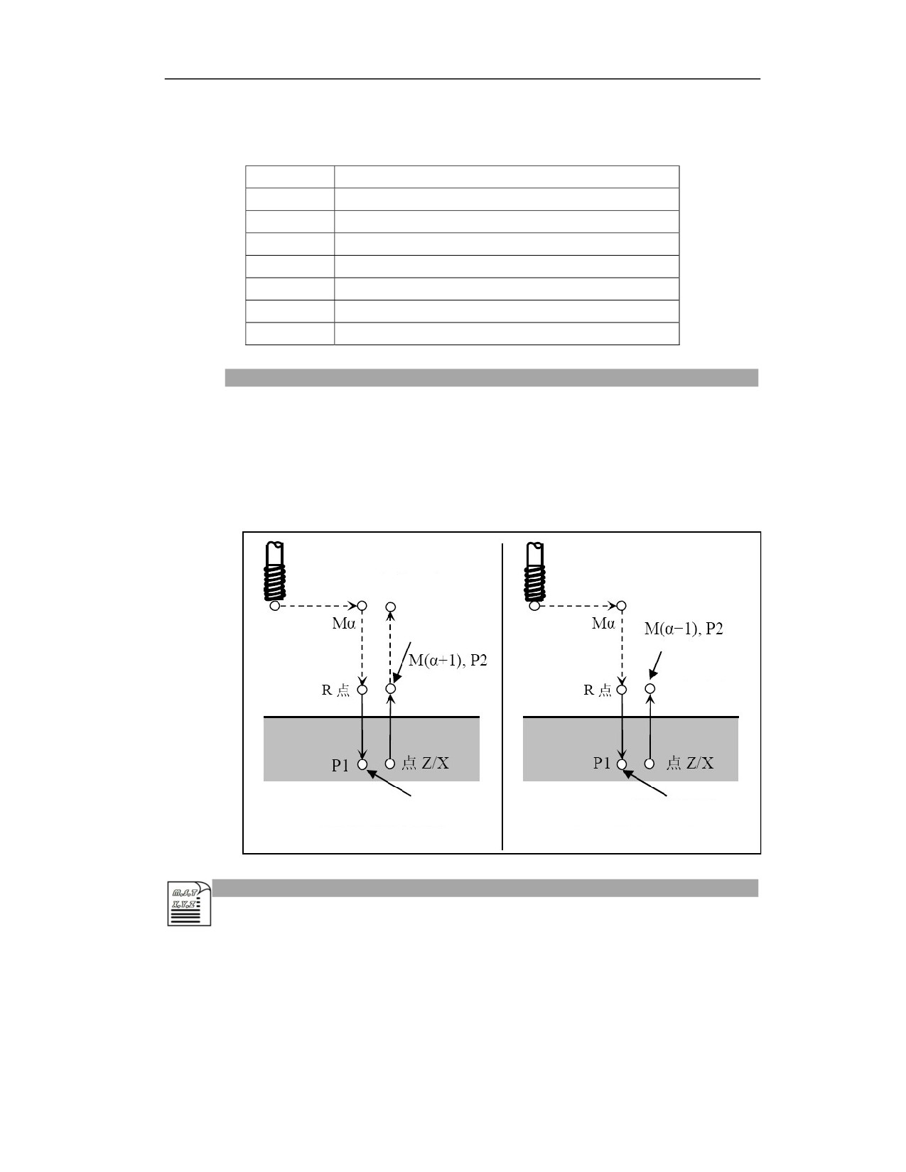
When executing this cycle, along the axis of the tool, the spindle rotates clockwise and taps to the
bottom of the hole, and then the spindle counterclockwise rotates and retracts. According to the
G98 or G99 command, the tap returns to the initial plane (G98) or the R level (G99). The specific
trajectory is shown in the figure below.
Initial level
Spindle rotation CW
Spindle rotation
CW
Point R level
Spindle rotation CCW
Spindle rotation CCW
G84 or G88 (G98)
G84 or G88 (G99)
Example
%1111
M3 S1=1000; No. 1 spindle rotates
G0X50Z50
M5
20
G84Z-10R20P1000F1000H1
M33 S2=1000; No. 2 spindle rotates
G4P1000
M55
G84Z-10R20P1000F1H2
G88X-10R20P1000F1
M30
Note
(1) If the processing mode H is not specified in the first line, the H3 mode is defaulted, and the
tool dills directly to the hole bottom.
(2) If the tapping spindle is not defined, C axis tapping is the default.
(3) During G84 and G88 rigid tapping, the feedhold and feedrate override modification are not
allowed.
(4) For G84 rigid tapping, when P parameter 37 is set to 0, servo spindle tapping is selected; when
P parameter 37 is set to 1, PMW spindle tapping is selected.
(5) Spindle rotates first during G84 tapping.
(6) Movement on Y axis is not supported for G88 radial drilling
(7) PMW spindle is not supported for G88.
14.3
FANUC Mode of Lathe System
Function and Purpose
HCNC lathes system is compatible with the FANUC standard program format, which realizes the
universality of the program and facilitates the user's program management.
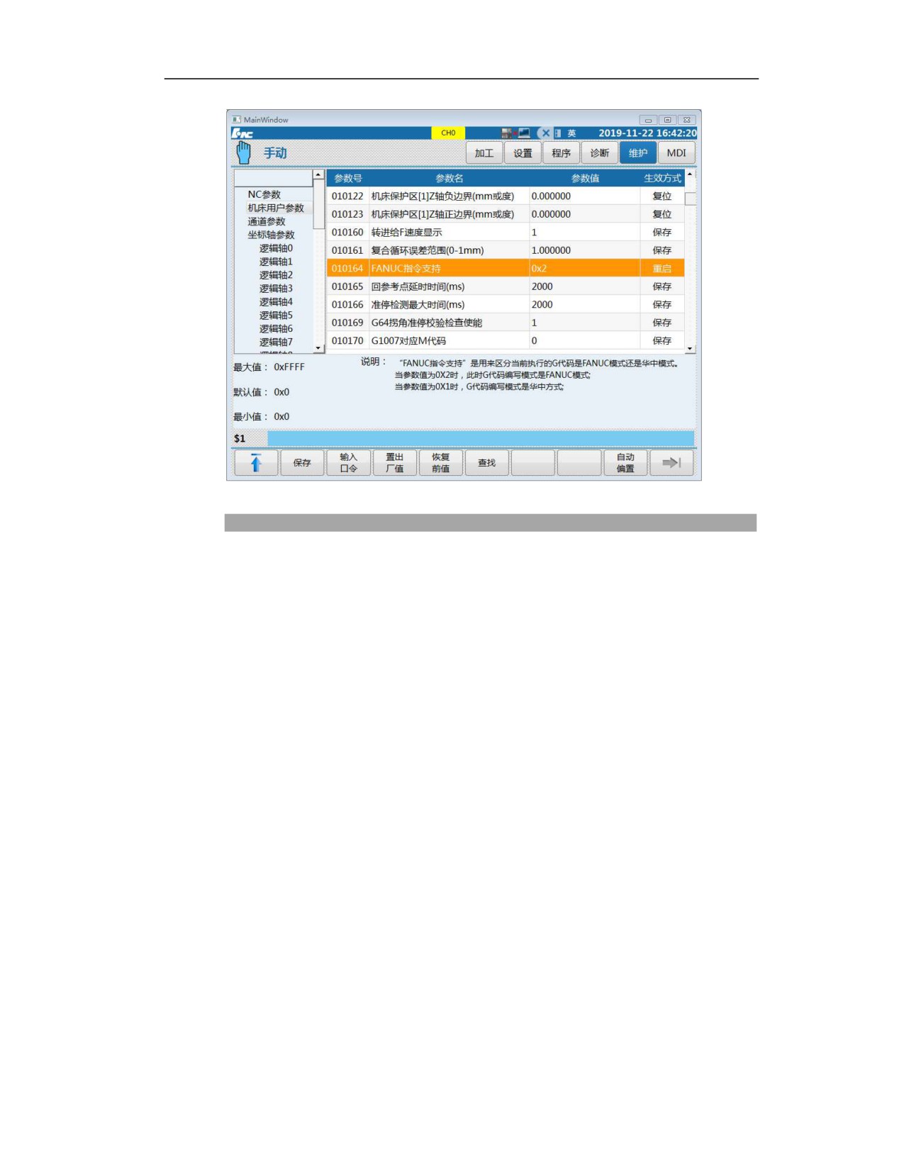
When the parameter "010164 FANUC command support" is set to 0X2, the programming format
of the lathe system is switched to the FANUC program format. At this time, the HCNC
programming format can no longer be used.
Due to the essential difference between the two systems, the HCNC system is mainly compatible
with FANUC's standardized programming format. For the non-standard formats not specified in
the FANUC manual, the HCNC system cannot achieve complete compatibility.
This section focuses on the attentions for using FANUC mode in HCNC system.
20
Description
1. Note for FANUC mode canned cycle:
When G83 and G84 are used in combination, the R value in G84 cannot be omitted. The
modal of the R value across the canned cycle are not inherited;
P and Q in G74 and G75 can support decimals (unit is um), but FANUC only supports
integers, and will alarm when it is decimal;
P and Q in G76 can support decimals (unit is um), while FANUC only supports integers,
and will alarm when it is decimal;
G74 and G75 do not support each execution of a feed P as a single block, but the
completion of entire execution as a single block
When the G92 is executed in single block, the feed will be held at the starting point of
the cycle after one cutting is finished. It does not support step-by-step operation during
threading. In addition, the feed hold button is invalid during the thread cutting process,
and it does not support FANUC's return to the cycle start point after pressing the feed
hold;
G76 in HCNC format is not allowed in FANUC mode;
For all canned cycles, if only the canned cycle G code is specified without any
commands after it, the canned cycle will be skipped directly.
20
2. Note for multiple repetitive cycle in FANUC mode:
G71 retraction mode: retreat by one feed amount from the highest point of all points in
the canned cycle;
G71 and G72 are only allowed to establish and cancel tool compensation in ns and nf
blocks. While tool compensation is established before entering G71 and G72 in FANUC;
In the rough turning cycle G71, the movement cycle action to the turning starting point
is G00, while G00 and G01 modes can be selected in FANUC.
The retraction from the bottom of G71 with groove: after the last cutting at the bottom
is completed, the tool moves along the contour, and then performs the next groove
cutting.
For the G72 with groove, even if the finishing amount on X is specified in the program,
the finishing amount on X is not reserved.
For the G71 with groove, even if the finishing amount on Z is specified in the program,
the finishing amount on Z is not reserved.
3. Note for parameter setting in FANUC mode
NC parameter 000023 F feedrate display mode can only be set to 0 and 1. 0 is set as the
actual speed, and 1 is set as the specified speed. When 1 is set, the F value always
displays as the specified value during G84 tapping.
For the machine user parameter 010164, setting of 2 indicates FANUC mode, and
setting of 1 indicates HCNC mode.
The channel parameter 040179 maximum angle threshold of collinearity judgment is
set to the default value 0.017.
The default value of the machine user parameter 010160 F speed display is set to 0.
The machine user parameter 010161 is the special parameter in the FANUC mode, and
it is used as the non-monotonic alarm tolerance in Z direction of the multiple repetitive
cycle.
The tool offset must be specified with the T command before G50.
20
15 Canned Cycle for Milling System (M)
15.1
Standard Canned Cycle for Milling System
Function and Purpose
There is a relatively fixed operating sequence for the processing of hole parts. With this function,
the canned cycle subprogram can be called through a single block to complete a fixed processing
action. Therefore, programming can be simplified, and memory can be effectively used. Table
15.1(a) is the canned cycle command list of the CNC system.
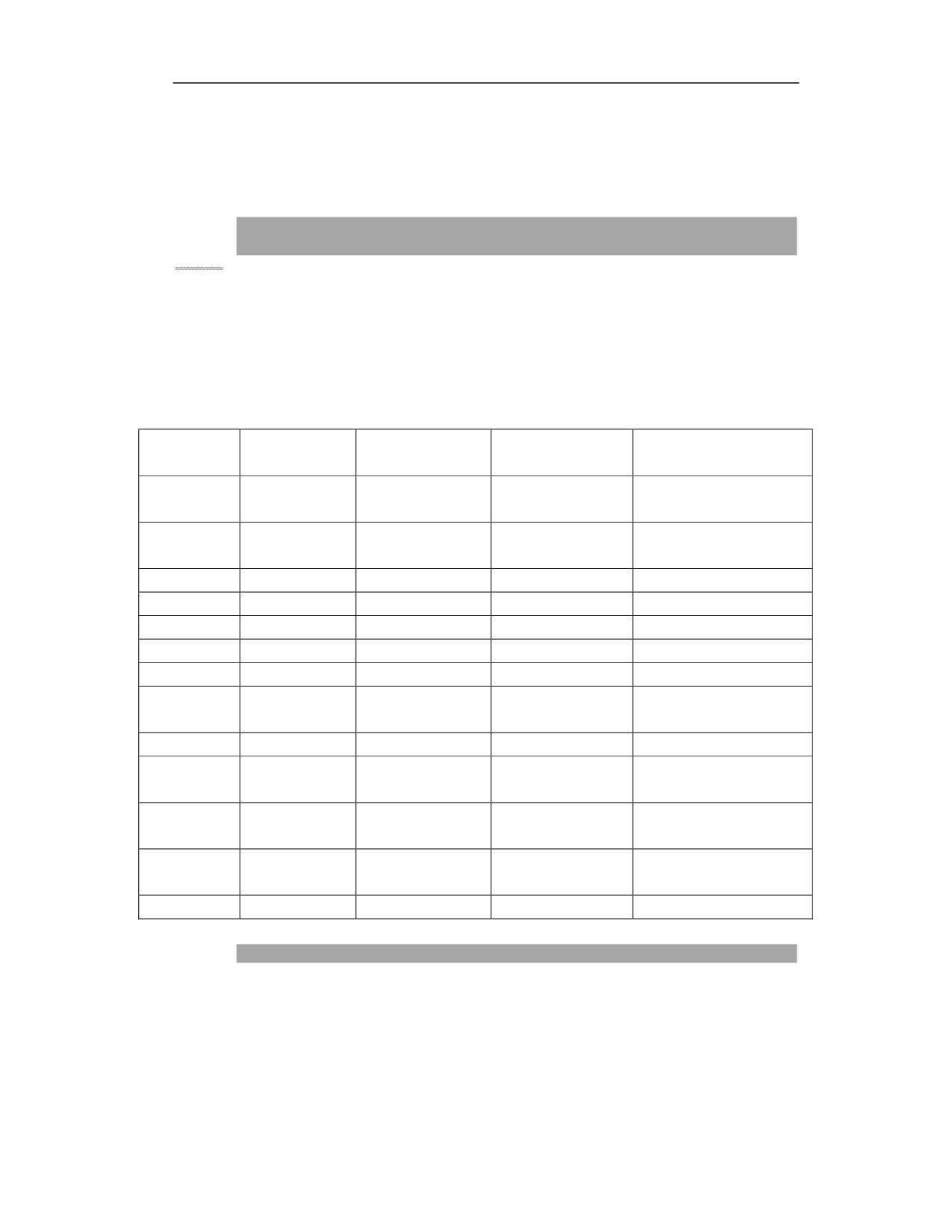
Table 15.1 (a) Drilling canned cycle list
Drilling (-Z
Action at hole
Retraction (+Z
G command
Use
direction)
bottom
direction)
Intermittent
High-speed deep hole
G73
Dwell
Rapid traverse retract
cutting feed
drilling cycle
Dwell—spindle
G74
Cutting feed
Cutting retract
Reverse tapping
rotation CW
G76
Cutting feed
Spindle orientation
Rapid traverse retract
Fine boring
G80
——
——
——
Cancel cycle
G81
Cutting feed
——
Rapid traverse retract
Spot drilling, boring
G82
Cutting feed
Dwell
Rapid traverse retract
Drilling, boring
G83
Cutting feed
Dwell
Rapid traverse retract
Deep hole drilling cycle
Dwell—spindle
G84
Cutting feed
Cutting retract
Tapping cycle
rotation CCW
G85
Cutting feed
——
Cutting retract
Boring
Dwell—spindle
G86
Cutting feed
Rapid traverse retract
Boring
stop
Spindle rotation
G87
Cutting feed
Rapid traverse retract
Reverse boring
CW
Dwell—spindle
G88
Cutting feed
JOG
Boring
stop
G89
Cutting feed
Dwell
Cutting retract
Boring
Description
Generally there are the following six sequential actions for the hole machining cycle:
Sequential action 1: X and Y axis positioning (different planes may have different positioning
axes)
Sequential action 2:rapid traverse to machining plane R point
20
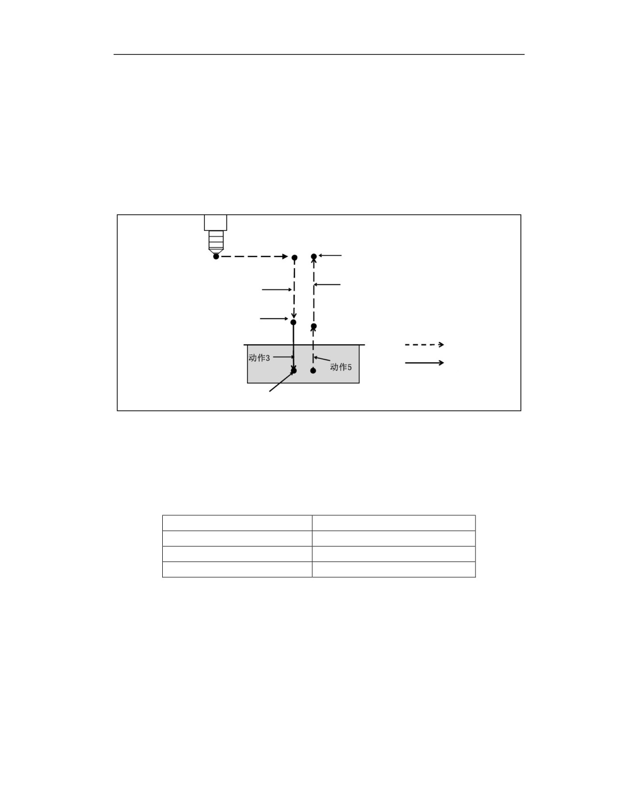
Sequential action 3: execute drilling action
Sequential action 4: action at hole bottom (hole buttom level Z point)
Sequential action 5: retract to R level
Sequential action 6: retract to the initial level B point in rapid traverse
Detailed breakdown is shown in Figure 1.1 (a)
Action 1
Initial level
Action 6
Action 2
R point
Rapid traverse
Feed
Hole bottom
Figure 1.1(a)
Positioning plane
The positioning plane is determined by the plane selection mode G17, G18, and G19.
The positioning axis is an axis other than the drilling axis.
Positioning plane
Positioning axis
G17
X, Y
G18
X, Z
G19
Y, Z
Drilling axis
Hole machining canned cycles include drilling cycles, tapping cycles, boring cycles, etc., but in
order to simplify the description, this section will collectively refer to various canned cycles as
drilling cycles, and drilling axis, tapping axis, and boring axis are collectively referred to as
drilling axis.
The drilling axis is a reference axis (X, Y, Z) that does not form the positioning plane or an axis
parallel to it.
The reference axis or parallel axis used as the drilling axis is determined by the positioning plane
20
of drilling (G17, G18, G19).
If the axis address of drilling axis is not specified, the reference axis is assumed to be the drilling
axis.
Positioning axis
Drilling axis
G17
Z-axis
G18
Y-axis
G19
X-axis
Drilling data
G73, G74, G76 and G81 to G89 are all modal G code commands, which are valid until they are
cancelled. In these drilling cycle commands, the specified parameters are also modal data,and are
kept until they are modified or cleared.
Length compensation G43/G44/G49
G73, G74, G76, and G81 to G89 drilling canned cycles can use tool length compensation. The
compensation point is used to establish compensation in the initial plane. G43 is for positive
compensation, and G44 is for negative compensation. The use of compensation needs to be
established with the tool compensation table. Different tool compensation registers are called to
achieve different compensation data.
Note: Through NC parameter 000012 Tool Axis Selection Mode, the Z axis can always be set as
the drilling axis. When the parameter is set to 0, the tool length compensation is always
compensated on the Z axis. When the parameter is set to 1, the compensation axis is switched
based on the machining coordinate selection plane. See drilling axis positioning plane.
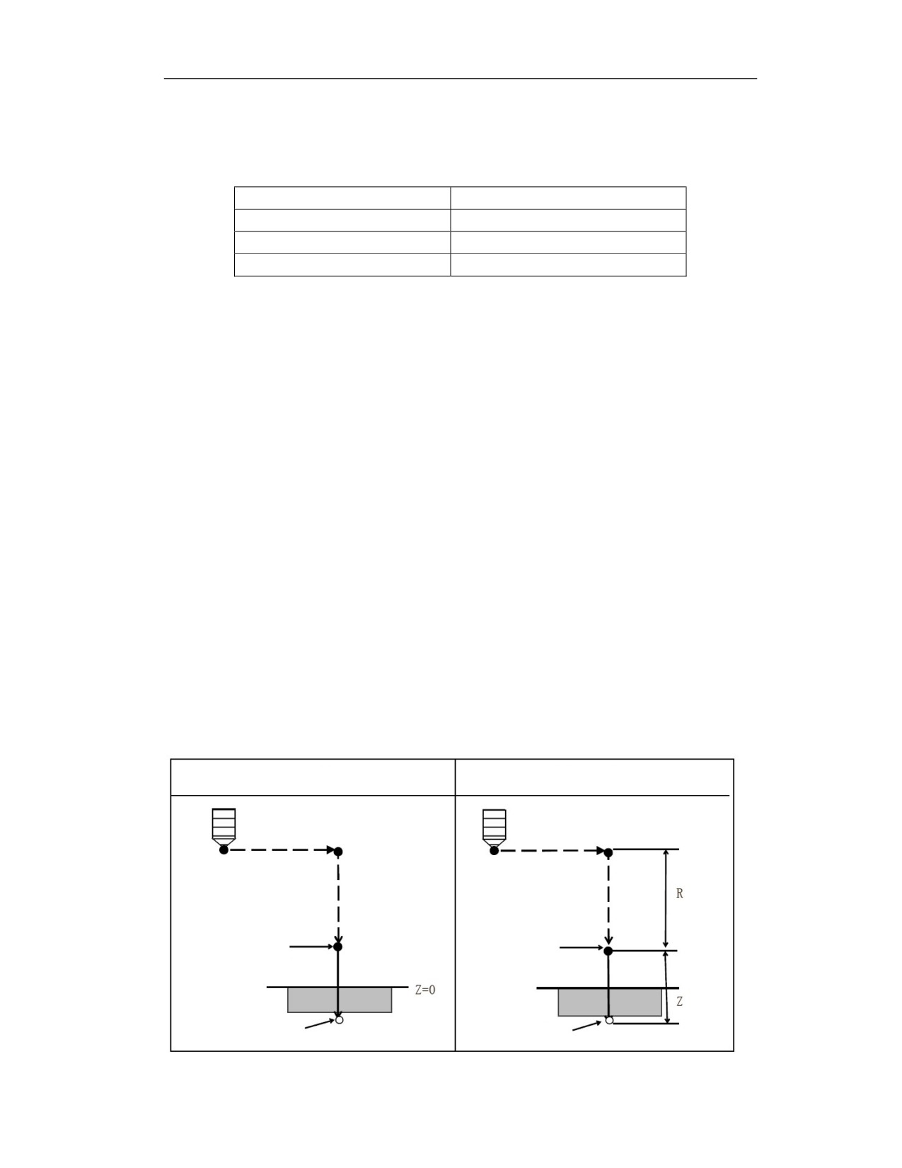
Movement amount of drilling axis G90/G91
The movement amount on the drilling axis can be expressed by the coordinate value of the
positioning point or the relative movement amount, which is specified by the G90 or G91
command in the program, as shown in Figure 1.1(b):
G90 (absolute command)
G91 (incremental command)
Point R
Point R
Point Z
Point Z
20
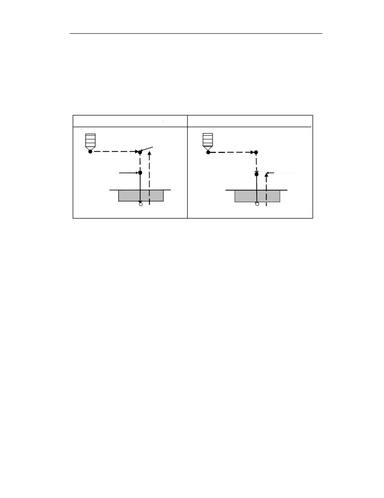
Figure 1.1(b)
Return to plane G98/G99
Whether to return the tool from the hole bottom to the machining level (point R) or to the initial
level (point B) is specified by G98 and G99. Figure 1.1(c) shows the action when G98 or G99 is
specified. Generally, G99 is used for the first drilling and G98 is used for the final drilling. Even
if drilling is performed in G99 mode, the initial level will not be changed.
G98 (return to initial level)
G99 (return to R level)
Initial level
Point R level
Point R
图 1.1(c)
Repeat
When user wants to repeat equidistant drilling, use L_ to specify the number of repetitions with
G91 relative coordinate command.
L is only valid in the block where it is specified.
Specify the position of the first hole in incremental mode (G91).
If it is specified in absolute mode (G90), the drilling is repeated at the same hole position.
Maximum value of number of repetitions L is 9999
Specify 0 or an integer value from 1 to 9999 for L.
Single block
When the hole machining cycle is performed in a single block, the control device stops at the end
points 1, 2, and 6 in Figure 1.1(a). Therefore, 3 times are required to drill a hole. At the end of
actions 1 and 2, the indicator light of feed dwell lights u. At the end of action 6, if the number of
repetitions is left, it will stop by feeding dwell. If there is no repetition number, it will stop in the
single block stop state. In addition, the R point of G87 will not stop. G88 also stops after dwell at
point Z.
Cancel
G80 or the 01 group of G codes is used to cancel the canned cycle.
21
The 01 group of G codes include:
G00 : positioning (rapid traverse)
G01 : linear interpolation
G02 : circular interpolation or helical interpolation (CW)
G03 : circular interpolation or helical interpolation (CCW)
G60 : unidirectional positioning
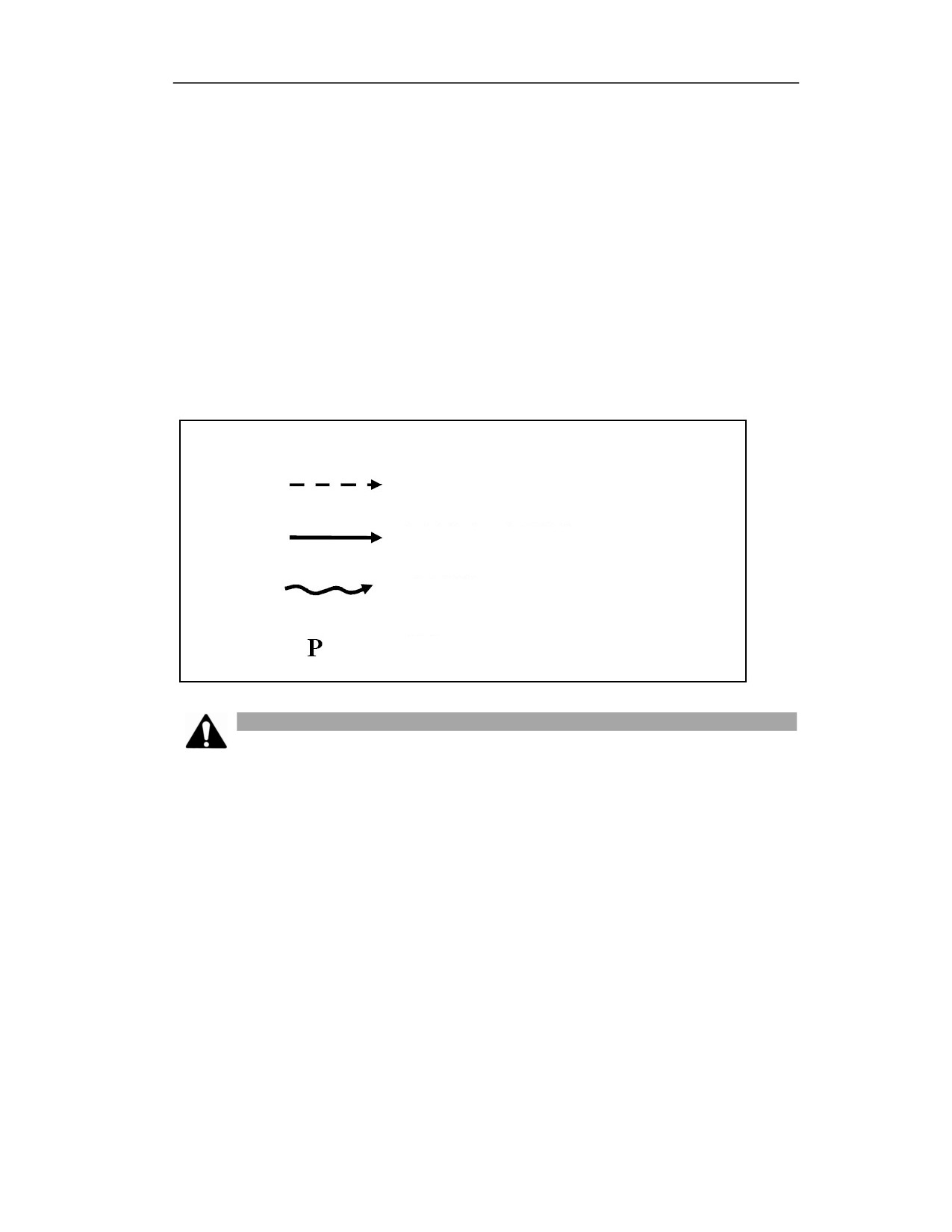
Explanation of symbols in the figure
The following describes each canned cycle.
The images used in these descriptions are represented by the following symbols.
Positioning (rapid traverse G00))
Cutting feed (linear interpolation G01)
Manual feed
Dwell
Note
1) When executing a canned cycle block that does not contain X, Y, Z traverse axis
commands, this line will not produce tool movement, but the cycle parameter modal
value of the current line will be saved;
2) Specifying the 01 group of G codes or specifying G80 will cancel the current canned
cycle G code modal, and also clear the cycle parameter modal value;
3) If the canned cycle needs to be repeated by specifying L, when L is specified as 0, an
alarm message will appear;
4) When using G53 command in a canned cycle block, its positioning data X, Y are still
the original workpiece coordinate system data, not the coordinate system data specified
by G53;
5) When switching the drilling axis for drilling, please cancel the drilling canned cycle;
6) To use this canned cycle function, user needs to set the machine user parameter 010083
drilling canned cycle type to 0 to call the HCNC canned cycle.
21
15.2
High-speed Deep-hole Drilling Cycle(G73)
Function and Purpose
This cycle is for high-speed deep hole drilling. When this command is executed, the tool
intermittently cuts and feeds to the bottom of the hole. Intermittent feed makes it easy to break
chips, remove chips, add coolant adding during deep hole machining, and the amount of tool
retraction is not large.
Command Format
(G98/G99) G73 X_ Y_ Z_ R_ Q_ P_ K_ F_ L_;
Parameter
Meaning
Coordinate position of hole center in XY plane in absolute programming (G90);
X Y
The incremental value of hole center relative to the starting point in XY plane in
incremental programming (G91);
Coordinate value of Z point of hole bottom in absolute programming; incremental value of
Z
Z point of hole bottom relative to the reference point R in incremental programming (G91);
Coordinates of reference point R in absolute programming (G90); the incremental value of
R
reference point R relative to the intial point B in incremental programming (G91);
Q
Hole drilling depth downward (incremental value, negative);
P
Dwell time at the hole bottom, in the unit of ms
K
Retraction amount upward (incremental value, positive)
F
Feedrate of drilling;
L
Cycle times (when repeat drilling is needed)
G73(G98)
G73(G99)
21
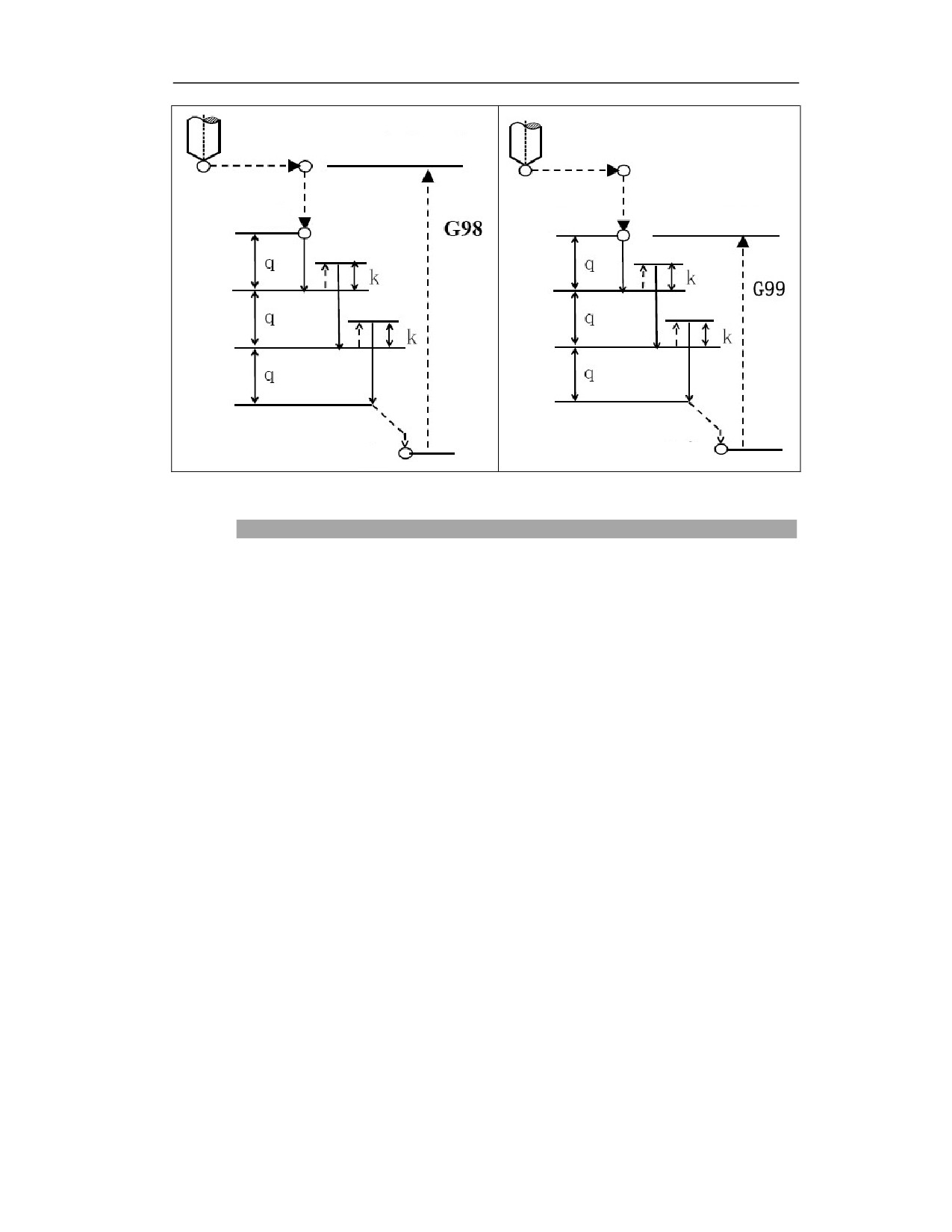
Initial level
Point R
Point R
Point R level
Point Z
Point Z
Description
Drilling action
(1)Tool position point moves to B point above the hole center in rapid travers;
(2)Rapid traverse to workpiece surface R point;
(3)Drill downward at F speed with depth of q;
(4)Tool retracts upward with distance of K;
(5)Repeat steps 3 and 4 several times;
(6)Drill to Z point at hole bottom;
(7)Pause at the hole bottom P seconds (spindle keeps rotating);
(8)Return to R point (G99) or B point upward.
The high-speed deep hole drilling cycle executes intermittent feed along Z axis. When this
cycle is used, the chips can be easily discharged from the hole, and a small retraction value
can be set, which allows effective drilling.
Use the auxiliary function to rotate the spindle before specifying G73 (M code).
When G73 code and M code are specified in the same block, the M code will be executed at
the same time as the first positioning action, and then the system will process the next drilling
action.
When the number of repetitions L is specified, the M code is only executed in the first hole,
and the M code is not executed in the second and subsequent holes
21
When the tool length offset (G43, G44 or G49) is specified in the canned cycle, the offset is
added while positioning to the R point
When Z, K, Q movement amounts are zero, this command is not executed.
|Q|>|K|;
Example
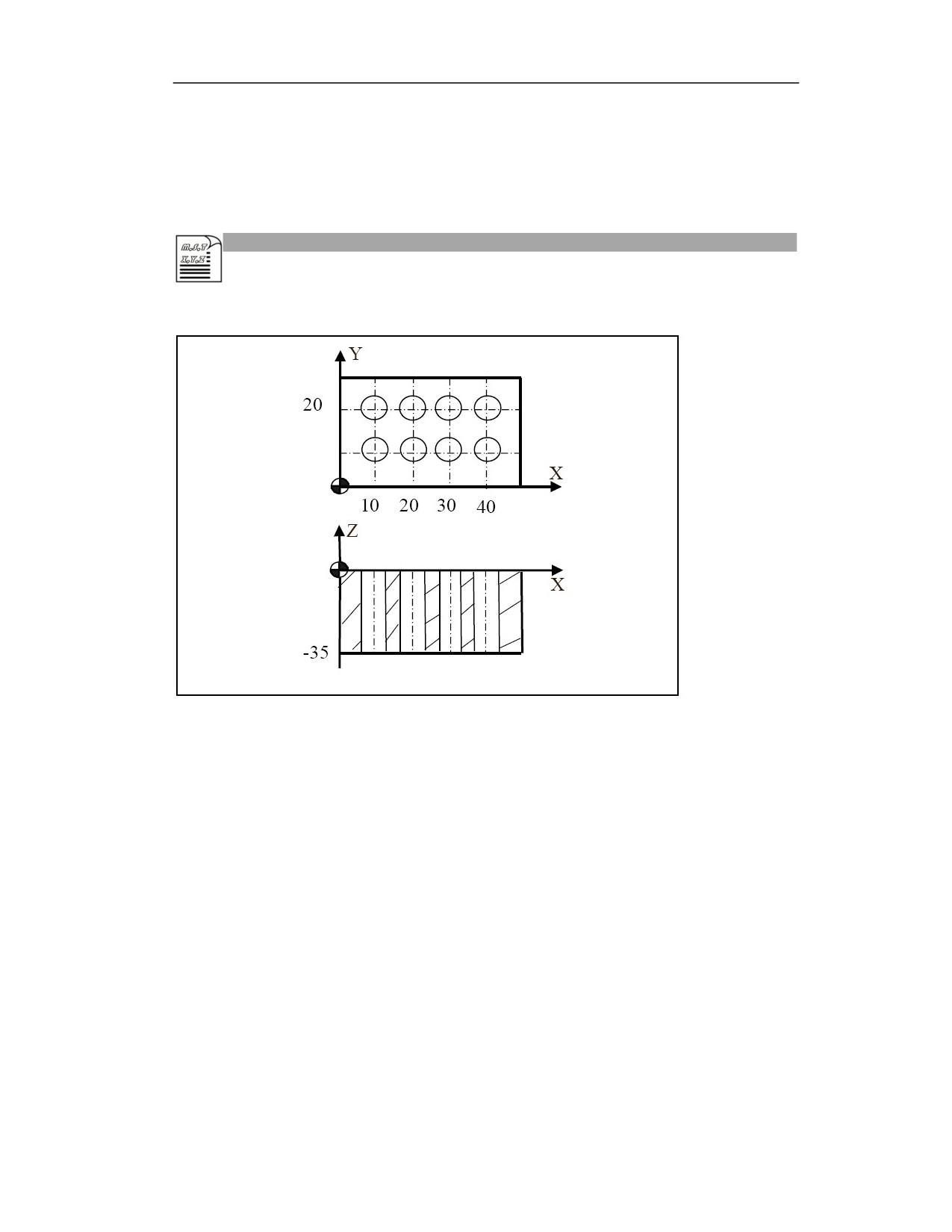
Process the holes as shown in the figure below:
Example 1 (absolute programming, return to R level):
N10 G54 G0 X0 Y0 Z80;Establish coordinate system, move to the safe starting point
N20 M03 S500; Spindle rotates CW
N30 G0 Z20; Position to the intial level
N40 G99 G73 X10 Y10 Z-35 R5 Q-3 K1 F200; After positioning, perform drilling 1,
and return to R level
N50 X20; After positioning, complete all drilling, and return to R level
N60 X30
N70 X40
N80 Y20
N90 X30
N100 X20
N110 X10
N120 G80; Cancel G73 canned cycle
N130 G28 G91 X0 Y0 Z0; Return to reference point
N140 M30; Program ends
21
Example 2 (absolute and incremental mixed programming, return to the initial level):
N10 G54 G90 G0 X0 Y0 Z80; Establish coordinate system, move to the safe starting
point
N20 M03 S500; Spindle rotates CW
N30 G0 Z20; Position to the intial level
N40 G98 G73 X10 Y10 Z-35 R5 Q-3 K1 F200; After positioning, perform drilling 1,
and return to R level
N50 G91 X10 L3;Increment X10 in turn to complete all drilling, and then return to the
initial level
N60 Y10
N70 X-10 L3
N80 G80; Cancel G73 canned cycle
N90 G28 G91 X0 Y0 Z0; Return to reference point
N100 M30; Program ends
Note
(1) Axis switching: Before switching the drilling axis, the canned cycle must be cancelled.
(2) Modality: G73 command data is stored as modal data, and the same data can be omitted.
(3) Drilling: Do not drill in the block that does not include X, Y, Z, R or any other additional axis.
If the moving position of Z is zero, the command is not executed.
(4) Q/R: Specify Q/R in the drilling block. If they are specified in the drilling block, they cannot
be stored as modal data.
(5) Cancel: Do not specify the G codes of group 01 (G00 to G03, etc.) in the G73 block. Otherwise,
G73 will be cancelled.
(6) Tool position offset: In the drilling canned cycle, the tool position offset is ignored.
21
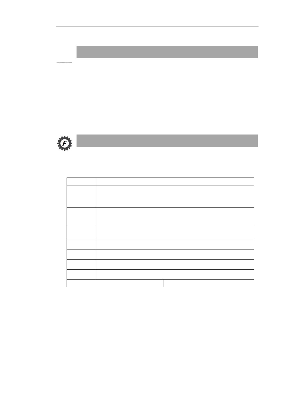
15.3
Reverse Tapping Cycle(G74)
Function and Purpose
This cycle is for reverse tapping. There are two types of reverse tapping. One is the reverse tapping
cycle. The tapping trajectory goes directly from point R to the point Z at the bottom of the hole;
the other is the reverse pecking tapping cycle. Repeated intermittent feed is performed during the
tapping process.
In the reverse tapping cycle, when the bottom of the hole is reached, the spindle rotates CW and
exits. During the tapping or retraction, the tool feeds a thread lead along the tapping axis for each
revolution of the spindle, the feed relationship does not change even during acceleration and
deceleration.
Command Format
15.3.1 Reverse Tapping Cycle
(G98/G99)G74 X_ Y_ Z_ R_ P_ F_ L_J_;
Parameter
Meaning
Absolute position of hole in absolute programming (G90);
X Y
The distance from the current position to the hole position in incremental
programming (G91).
Absolute position of hole bottom in absolute programming (G90);
Z
The distance from hole bottom to R point in incremental programming (G91).
Absolute position of R point in absolute programming (G90);
R
The distance from R point to initial level in incremental programming (G91).
P
The dwell time at the hole bottom, in the unit of ms.
F
Thread lead.
L
Repeat times (can be omitted when L=1).
J
J1 A-axis tapping; J2 B-axis tapping; J3 C-axis tapping.
G74(G98)
G74(G99)
21
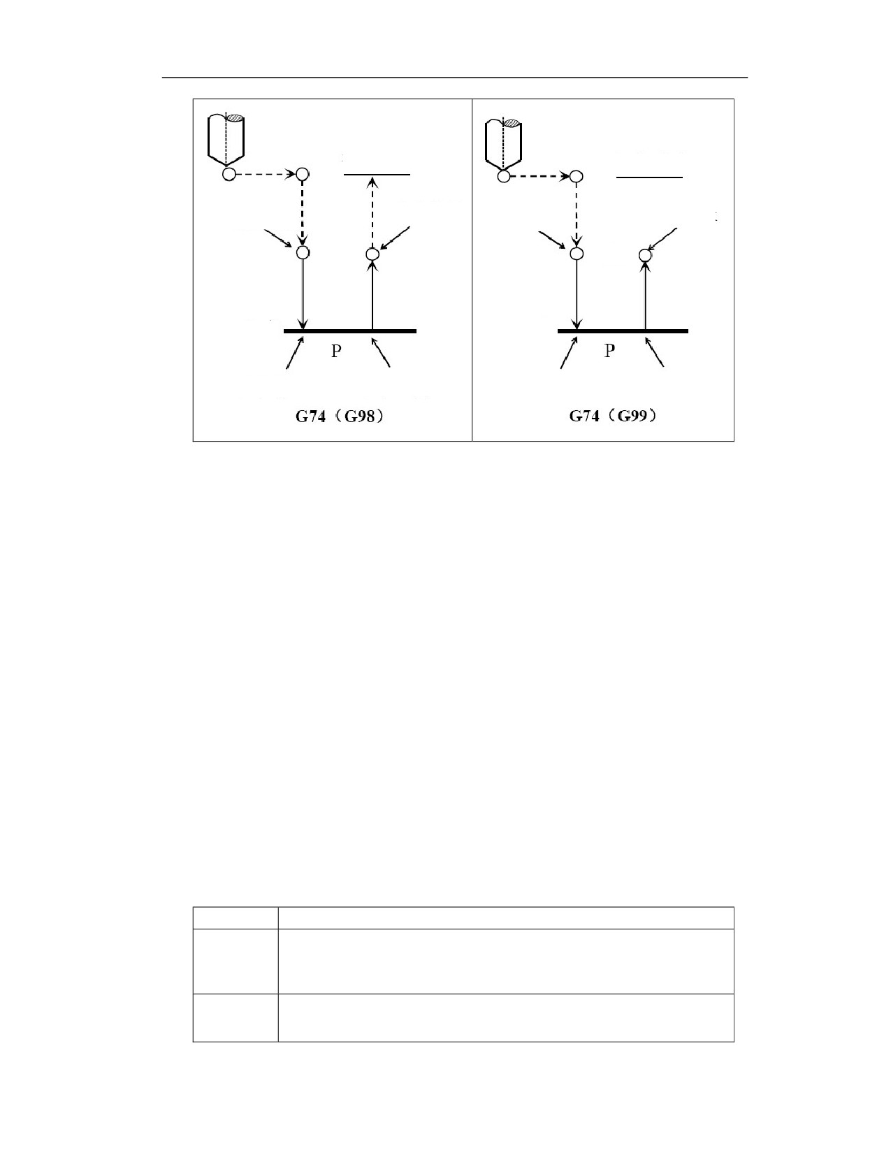
Initial level
Initial level
Spindle rotation
Spindle rotation
Spindle stop
Spindle stop
CCW
CCW
Point R
Point R
Point Z
Point Z
Spindle stop
Spindle rotation CW
Spindle stop
Spindle rotation CW
Reverse tapping action:
(1) Rotate the spindle through the auxiliary function, and the tool position point moves to point B
above the hole center in rapid traverse;
(2) The spindle rotates counterclockwise and rapid traverse to the surface of the workpiece to
point R
(3) The system calculates the feedrate based on the pitch speed, and taps at the feedrate downward.
The depth is Z;
(4) Tap to the hole bottom, and spindle stops;
(5) Dwell at the hole bottom after the dwell time (P) is specified;
(6) Spindle rotates CW, return to R point upward;
(7) Spindle stops;
(9) Return to R point (G99) or B point (G98);
15.3.2 Reverse Peck Tapping Cycle
(G98/G99)G74 X_ Y_ Z_ Q_ K_R_ P_ F_ L_E_J_
(Peck tapping)
Parameter
Meaning
The absolute position of hole in absolute programming (G90);
X Y
The distance from the current position to the hole position in incremental
programming (G91).
The absolute position of hole bottom in absolute programming (G90);
Z
The distance from hole bottom to R point in incremental programming (G91).
21
Q
The feed amount in peck tapping;
K
The retraction amount in peck tapping;
The absolute position of R point in absolute programming (G90);
R
The distance from R point to the intial level in incremental programming (G91).
P
The dwell time at the hole bottom, in the unit of ms;
F
The thread lead;
L
Repeat times (it can be omitted when L=1);
E
E1: Peck tapping, feed Q, retract K;
E2: Peck tapping, feed Q, return to R level.
J
J1 A-axis tapping; J2 B-axis tapping; J3 C-axis tapping.
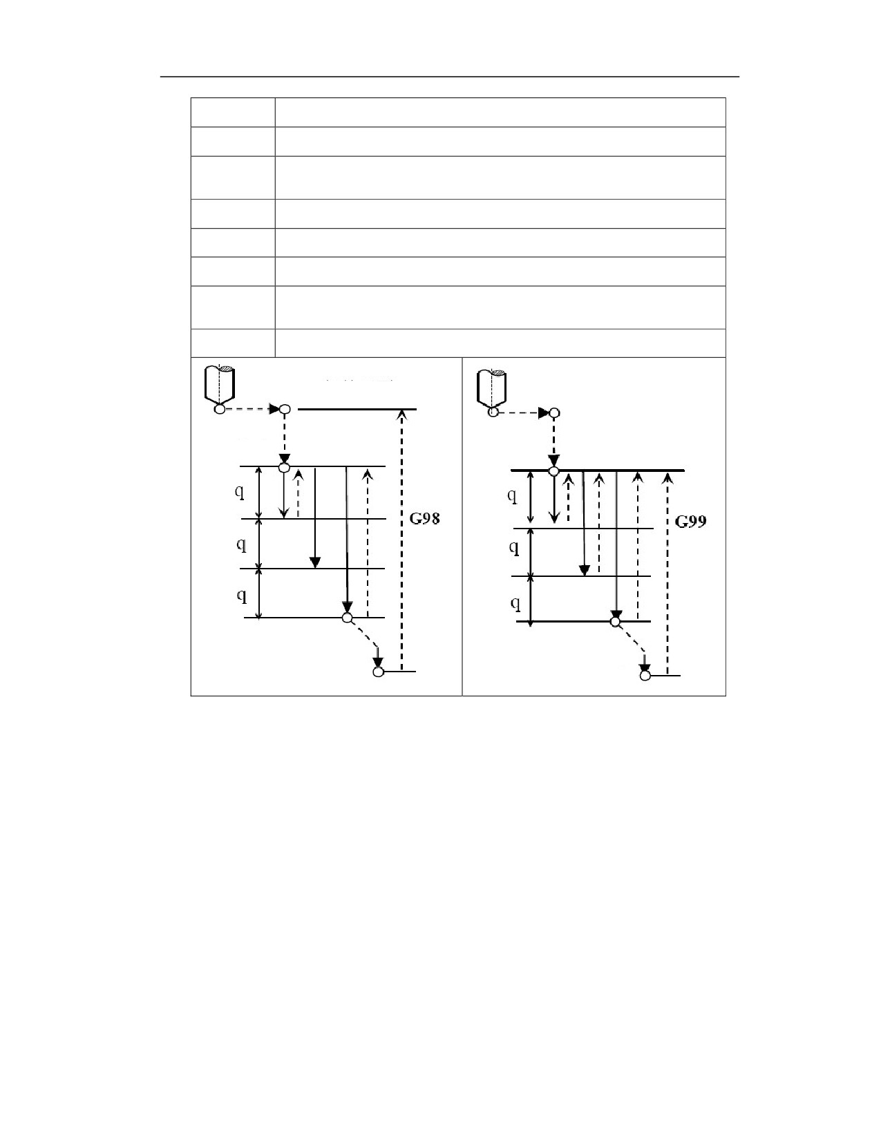
Initial level
Point R level
Point R
Point R
Point Z
Point Z
Reverse tapping cycle action (peck tapping):
(1) Rotate the spindle through the auxiliary function, and the tool position point moves to point B
above the hole center in rapid traverse;
(2) The spindle rotates counterclockwise and rapid traverse to the surface of the workpiece to
point R;
(3) The system calculates the feedrate based on the pitch speed, and taps at the feedrate downward.
The depth is Q;
(4) Spindle stops;
(5) When dwell time (P) is specified, dwell is performed;
(6) Spindle rotates clockwise, taps upwards and returns to R point;
(7) Spindle stops;
(8) Spindle rotates counterclockwise. Tap downward at the feedrate, the depth is (times*Q);
21
(9) Repeat steps 4, 5, 6, 7, 8, and arrive at Z point of hole bottom;
(10) Dwell P ms at hole bottom;
(11) Spindle rotates clockwise. Retract upward to R point (G99) or B point (G98) in rapid traverse.
Description
Perform tapping with spindle rotation CCW. When it reaches the bottom of the hole, the
spindle rotates clockwise for return. This cycle processes a reverse thread.
During reverse tapping, the feedrate override is omitted. The feed is paused, and the machine
doesn’t stop unit the retraction is completed.
Before G74 is specified, use the auxiliary function (M code) to counterclockwise rotate
spindle.
When G74 command and M code are specified in the same block, the M code will be
executed at the same time as the first positioning action, and then the system will process the
next drilling action.
When the number of repetitions L is specified, the M code is only executed for the first hole,
and is not executed for the second and subsequent holes.
When the tool length offset G43, G44 or G49 is specified in the canned cycle, the offset is
added while positioning to the R point.
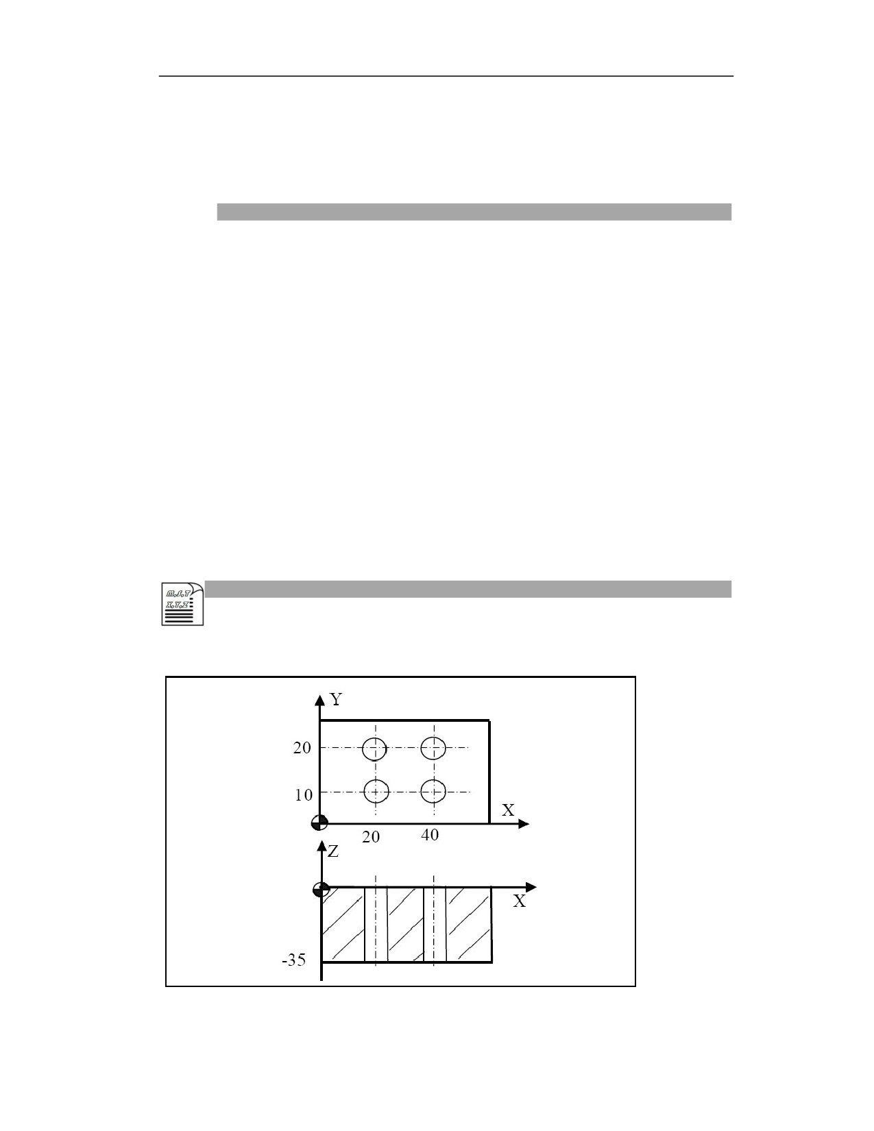
Example
Process the holes as shown in the figure below:
Example 1 (Absolute programming, tapping, return to R level)
21
%3343
N10 G54 G0 X0 Y0 Z80; Establish coordinate system, move to safe starting point;
N20 M04 S500; Spindle rotation CCW starts;
N30 G0 Z20; Position to the initial level;
N40 G99 G74 X20 Y10 Z-35 R5 P500 F1; Complete the tapping of hole 1 after
positioning, then return to R level
N50 X40; Complete tapping of all holes, then return to R level
N60 Y20
N70 X20
N80 G80; Cancel G74 tapping cycle
N90 G28 G91 X0 Y0 Z0; Return to reference point
N100 M30; Program ends
Example 2 (absolute, incremental mixed programming, peck tapping, return to initial level)
%3343
N10 G54 G90 G0 X0 Y0 Z80; Establish coordinate system, move to safe starting
point;
N20 M04 S500; Spindle starts;
N30 G0 Z20; Position to the initial level;
N40 G98 G74 X20 Y10 Z-35 R5 Q-3 K2 E1 F1; Perform peck tapping of hole 1 after
positioning, then return to initial level;
N50 G91 X20; Perform peck tapping of the remaining 3 holes, then return to initial
level;
N60 Y10
N70 X-20
N80 G80; Cancel G74 canned cycle;
N90 G28 G91 X0 Y0 Z0; Return to reference point;
N100 M30; Program ends.
Note
(1) F feedrate in tapping: F (feedrate) specified in the program is invalid during rigid tapping, and
the feedrate along the tapping axis is calculated by the following formula: feedrate = spindle speed
× thread lead
(2) Tapping method: C-axis tapping, the servo spindle is regarded as the C-axis, and the
interpolation method is used to tap, which can achieve high-speed and high-precision tapping.
(3) Axis switching: please cancel canned cycle before switching drilling axis.
(4) Modality: G74 command data is stored as modal data, and the same data can be omitted.
(5) Reverse tapping: do not drill in the block that does not contain X, Y, Z, R or any other
additional axis. If the moving position of Z is zero, the command will not be executed; point Z
must be lower than the level of point R, otherwise alarm will be issued.
22
(6) Position mode G108 or STOC: Before using the tapping command G74, please pay attention
to use STOC command to switch the control mode of the spindle servo motor from speed mode
to position mode. After tapping is completed, user can use CTOS to switch the control mode of
the spindle servo motor from position mode to speed mode, and the servo spindle is used as a
normal spindle.
(7) Cancel: Do not specify the G codes of group 01 (G00 to G03, etc.) in the G74 block. Otherwise,
G74 will be cancelled.
(8) Tool position offset: In the drilling canned cycle mode, the tool position offset is ignored.
(9) R: Specify R in the drilling block. If R is specified in the non-drilling block, it cannot be stored
as modal data.
(10) P: Please specify P in the drilling block. If it is specified in the non-drilling block, it cannot
be stored as modal data.
(11) Q: Please specify Q in the drilling block. If it is specified in the non-drilling block, it cannot
be stored as modal data.
(12) Reset: When the reset is performed during rigid tapping, the rigid tapping mode cannot be
released, and the machine tool cannot stop the tapping action. Emergency stop is availarble.
(13) Feed hold, single block: In G74 (G84) mode, the feed hold will be executed after each tapping
action is completed, and the subsequent tapping will continue to be performed after pressing the
cycle start button. In single block mode, the feed hold will be executed after each tapping action
is completed, and the next tapping action will be completed after pressing the cycle start button.
(14) Machine lock: The machine lock is also valid for G74 (G84). Even if G74 (G84) is executed
when the machine is locked, the drilling axis will not move. Therefore, the spindle will not move.
15.4
Fine Boring(G76)
Function and Purpose
This cycle is for precision hole boring.
In the fine boring cycle, when the bottom of the hole is reached, the spindle stops cutting, and the
tool nose leaves the machining surface of the workpiece and returns.
Command Format
(G98/G99) G76 X_ Y_ Z_ R_ I_ J_ P_ F_ L_;
Parameter
Meaning
Absolute position of hole in absolute programming (G90);
Distance from the current position to position of hole in incremental programming
X Y
(G91).
UV programming is not supported.
22
Absolute position of hole bottom on Z in absolute programming (G90);
Z
Distance from the hole bottom to R point in incremental programming (G91).
Absolute position of R point on Z in absolute programming (G90);
R
Distance from R point to initial level in incremental programming (G91).
I
Offset on X, can only be positive;
J
Offset on Y, can only be positive;
P
Dwell time at hole bottom (unit: ms);
F
Cutting feedrate;
L
Repeat times (it can be omitted when L=1)
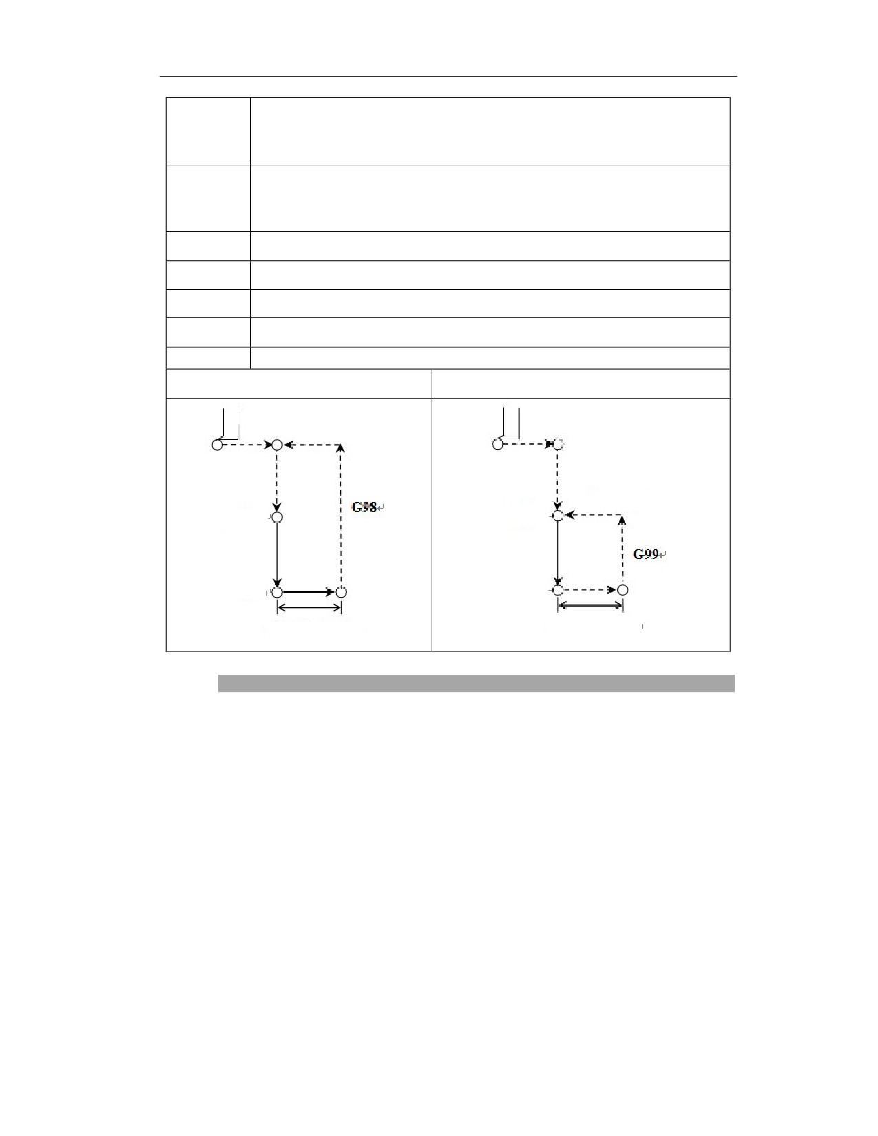
G76(G98)
G76(G99)
Initial level
R point level
R point
R point
Z point
Z point
Offset (I, J)
Offset (I, J)
Description
Fine boring cycle action
(1) Move to the tool position to point B above the hole center in rapid traverse
(2) Move close to the surface of the workpiece to point R in rapid traverse
(3) Bore downward at F speed, reach point Z at the bottom of the hole
(4) Dwell Z ms at hole bottom (spindle keeps rotating)
(5) Spindle orientation, spindle stops rotating
(6) The boring tool quickly moves I or J in the opposite direction of the tool nose
(7) Retract upward to R level (G99) or B level (G98) in rapid traverse
(8) Quickly move I or J in the positive direction of the tool nose, and the tool position point will
return to point R or B above the hole center
22
(10) Spindle resumes CW rotation
The drilling axis must be Z axis;
Z point must be lower than R level; otherwise an alarm will be issued;
G76 command data is stored as modal data, the same data can be omitted;
Before using the command G76, please use the corresponding M code to rotate the spindle.
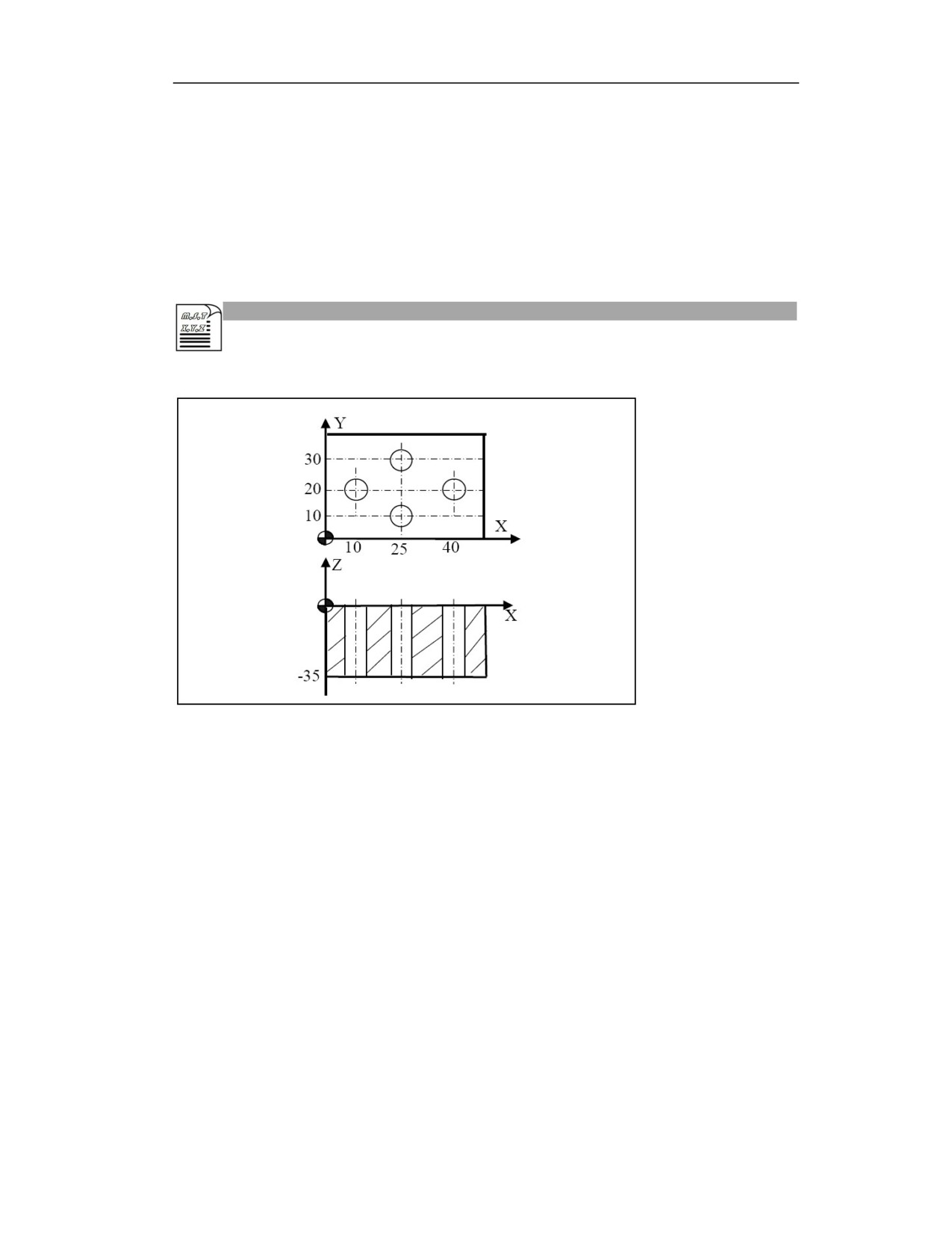
Example
Process the hole as shown below,
Example 1 (absolute programming, return to R level):
%3341
N10 G54 G90 G0 X0 Y0 Z80; Establish coordinate system, move to safe starting point
N20M03 S600; Spindle rotation CW starts
N30G00 Z20; Position to initial level
N40 G99 G76X10Y20 Z-35 R5 I1 P2000 F100; Complete boring of hole 1 after
positioning, return to the level of point R
N50X25 Y30; Complete boring of the remaining holes after positioning, return to the
level of point R
N60 X40 Y20
N70 X25 Y10
N80 G80; Cancel G76 boring cycle
N90 G91G28 X0 Y0 Z0; Return to reference point
N100 M30; Program end
Example 2 (absolute and incremental mixed programming, return to the initial level):
%3343
22
N10 G54 G90 G0 X0 Y0 Z80; Establish coordinate system, move to safe starting point
N20 M03 S500; Spindle rotation CCW starts
N30 G0 Z20; Position to initial level
N40 G98 G76 X10 Y20 Z-35 R5 I5 P500 F100; Complete boring of hole 1 after
positioning, return to the level of point R
N50 G91 X15 Y10; Complete boring of the remaining holes in incremental
programming, return to the initial level
N60 X15 Y-10
N70 X-15 Y-10
N80 G80; Cancel G76 boring cycle
N90 G28 G91 X0 Y0 Z0; Return to reference point
N100 M30; Program end
Note
(1) Axis switching: Before switching the boring axis, please cancel the canned cycle.
(2) Modality: G76 command data is stored as modal data, the same data can be omitted;
(3) Boring processing: do not drill in the block that does not include X, Y, Z, R or any other
additional axis. If the moving position of Z is zero, the command is not executed;
(4) I J R: if specify I J R in the boring block, I or J can only be a positive value. If I or J is specified
as a negative value, the sign is ignored. If they are specified in the non-boring block, they cannot
be stored as modal data;
(5) Cancel: Do not specify the G codes of group 01 (G00 to G03, etc.) in the G76 block. Otherwise,
G76 will be cancelled;
(6) Tool position offset: in the boring canned cycle mode, the tool position offset is ignored.
22
15.5
Drilling Cycle (Center Drills)(G81)
Function and Purpose
This cycle is for the normal drilling.
The feed cutting is performed to the hole bottom, and the tool returns from the hole bottom in
rapid traverse.
Command Format
(G98/G99) G81 X_ Y_ Z_ R_ F_ L_ ;
Parameter
Meaning
X Y
The hole position data. The absolute position of the hole in absolute programming, and
the distance from the current position to the hole position in incremental programming;
Z
The position of hole bottom. The absolute position of hole bottom on Z in absolute
programming (G90); the distance from hole bottom to R point in incremental
programming (G91);
R
Position of R point. The absolute position of R point on Z in absolute programming
(G90); the distance from R point to initial level in incremental programming (G91);
F
Cutting feedrate
L
Number of repetitions (can be omitted when L=1, generally used for multi-hole
processing, so X and Y should be incremental values)
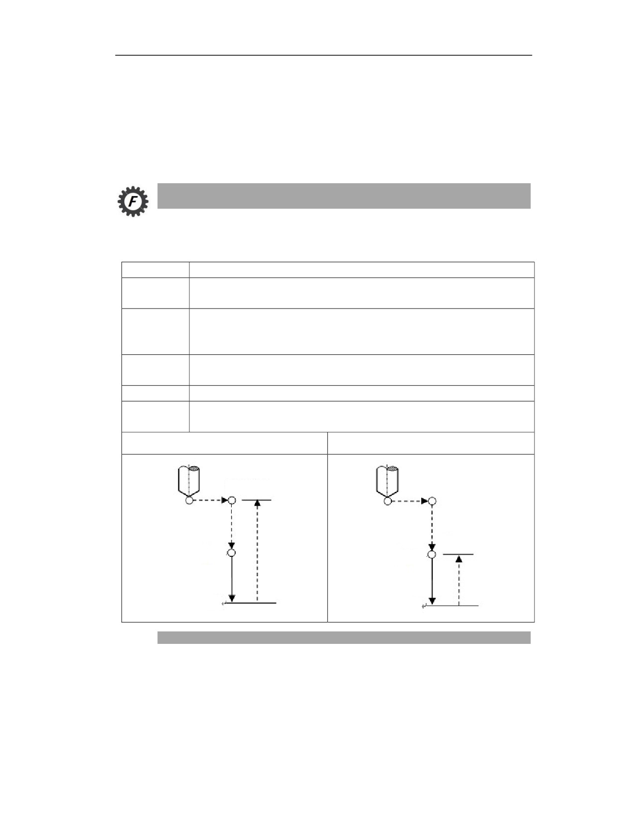
G81(G98)
G81(G99)
Initial level
R point level
R point
R point
Z point
Z point
Description
Action
Tool position point moves to the B point above hole center in rapid traverse;
Move close to the workpiece surface to R point in rapid traverse;
Drilling downward at F speed to the hole bottom Z point;
22
Spindle keeps rotating; retract upward to R point (G99) or B point (G98) in rapid traverse.
Spindle rotation
Before G81 is specified, the auxiliary function (M code) is used to rotate spindle.
Auxiliary function
When G81 and M code are specified in the same block, the M code is executed during the initial
positioning.
When the number of repetitions L is specified, the above actions will only be executed for the
first time. The M code will not be executed after the second time.
Tool length compensation
When tool length compensation (G43, G44, G49) is specified in the drilling canned cycle, the
compensation is used when positioning to the R point.
Example
Process the hole shown as below,
Example 1
%3343
G54G0 X0 Y0 Z30; Return to the safe height of workpiece zero
M03 S600; Spindle rotation CW
G0 Z10; Position to the initial plane
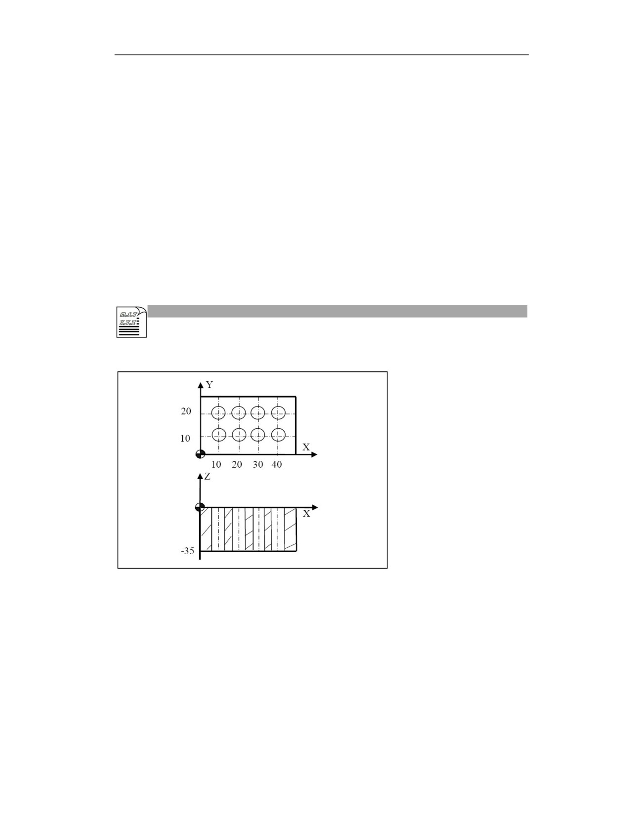
G90G99 G81 X10 Y10 R5 Z-35 F200; Position to the hole (10 10), perform drilling,
return to R level
G91X10L3; Drill the last three holes on horizontal axis, return to R level
Y10; Position to the hole (40 20), perform drilling, return to R level
G91X10L3; Drill the last three holes on horizontal axis
22
X-10L3; Drill the first three holes on horizontal axis, and return to R level
G80; Cancel drilling canned cycle
G28 G91 Z0; Return to machine zero of Z axis
G28 G91 X0 Y0; Return to machine zero of X axis and Y axis
M30; Program end
Note
(1) Axis switching: please cancel canned cycle before switching drilling axis.
(2) Modality: G81 command data is stored as modal data, the same data can be omitted;
(3) Drilling: Drilling cannot be in the block that does not include X, Y, Z, R or any other additional
axis. If the moving position of Z is zero, the command is not executed;
(4) Cancel: Do not specify the G codes of group 01 (G00 to G03, etc.) in the G81 block. Otherwise,
G81 will be cancelled.
(5) Tool position offset: In the drilling canned cycle mode, the tool position offset is ignored.
22
15.6
Drilling Cycle with Pause(G82)
Function and Purpose
This cycle is used for normal drilling, counternboring, and blind hole processing.
The cutting feed proceeds to the bottom of the hole. Tool pauses at the bottom of the hole, and
then retracts from the bottom of the hole in rapid traverse.
This cycle can improve the accuracy of the hole depth.
This command is the same as G81 except that it needs to pause at the bottom of the hole.
Command Format
(G98/G99) G82 X_ Y_ Z_ R_ P_ F_ L_ ;
Parameter
Meaning
X Y
The absolute position of the hole in absolute programming, and the distance from
the current position to the hole position in incremental programming;
Z
The absolute position of hole bottom in absolute programming (G90); the distance
from hole bottom to R point in incremental programming (G91);
R
The absolute position of R point in absolute programming (G90); the distance from
R point to initial level in incremental programming (G91);
P
Dwell time at the hole bottom (unit: ms)
F
Cutting feedrate
L
Number of repetitions (can be omitted when L=1, generally used for multi-hole
processing)
G82(G98)
G82(G99)
Initial level
R point level
R point
R point
Z point
Z point
Dwell
Dwell
22
Description
Action
(1) Tool position point moves to B point above hole center in rapid traverse;
(2) Move close to the workpiece surface to R point;
(3) Drill downward at F speed to Z point of hole bottom;
(4) Spindle keeps original rotating. Pause P ms
(5) Retract upward to R point (G99) or B point (G98)
Spindle rotation
Before G82 is specified, the auxiliary function (M code) can be used to rotate spindle.
Auxiliary function
When G81 and M code are specified in the same block, the M code is executed during the initial
positioning.
When the number of repetitions L is specified, the above actions will only be executed for the
first time. The M code will not be executed after the second time.
Tool length compensation
When tool length compensation (G43, G44, G49) is specified in the drilling canned cycle, the
compensation is used when positioning to the R point.
Example
22
Example 1
%3343
G54G0 X0 Y0 Z30; Return to the safe height of workpiece zero
M03 S600; Spindle rotation CW
G0 Z10; Position to the initial level
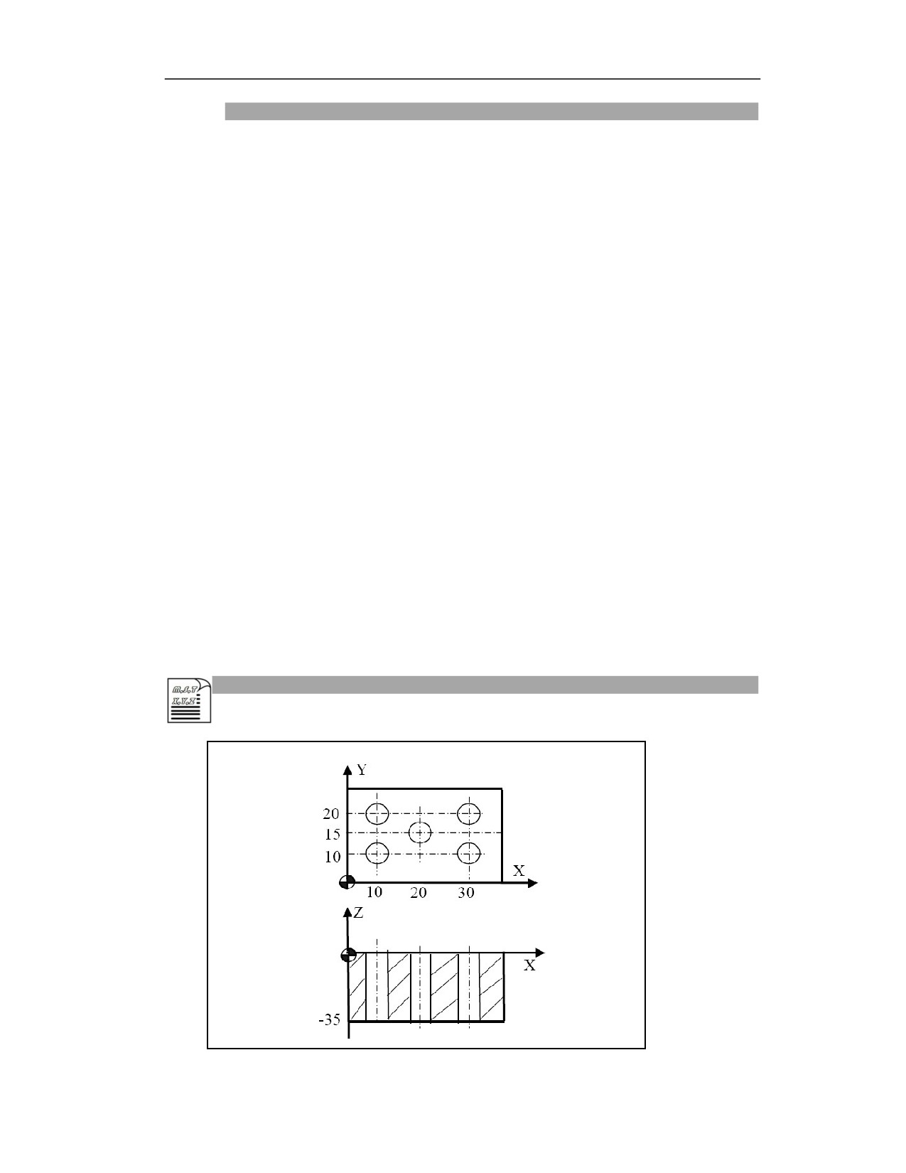
G99 G82 X10 Y10 R5 Z-35 P1000 F200; Position to the hole (10 10), perform drilling,
return to R level
X10Y20; Position to the hole (10 20), perform drilling, return to R level
Y20Y15; Position to the hole (20 15), perform drilling, return to R level
X30Y10; Position to the hole (30 10), perform drilling, return to R level
X30Y20; Position to the hole (30 20), perform drilling, return to R level
G80; Cancel drilling canned cycle
G28 G91 Z0; Return to machine zero of Z axis
G28 G91 X0 Y0;Return to machine zero of X axis and Y axis
M30
Note
(1) Axis switching: please cancel canned cycle before switching drilling axis;
(2) Modality: G81 command data is stored as modal data, the same data can be omitted;
(3) Drilling: Drilling cannot be in the block that does not include X, Y, Z, R or any other additional
axis. If the moving position of Z is zero, the command is not executed;
(4) Cancel: Do not specify the G codes of group 01 (G00 to G03, etc.) in the G82 block. Otherwise,
G82 will be cancelled.
(5) Tool position offset: In the drilling canned cycle mode, the tool position offset is ignored.
(6) P: Please specify P in the drilling block. If it is specified in the non-drilling block, it cannot be
stored as modal data.
15.7
Deep Hole Drilling Cycle (G83)
Function and Purpose
This cycle is for deep hole processing.
This canned cycle is used for intermittent feed on Z axis. After drilling of each hole downward,
the tool quickly retracts to the reference point R. The retraction amount is larger, which is better
for chip removal and coolant adding.
Command Format
23
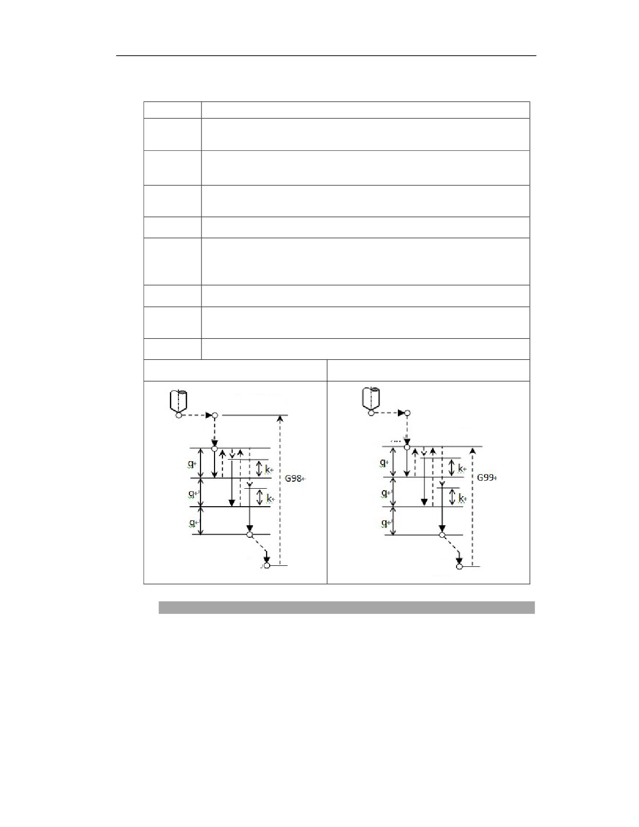
(G98/G99) G83 X_ Y_ Z_ R_ Q_ K_ F_ L_ P_;
Parameter
Meaning
The absolute position of the hole in absolute programming, and the distance from
X Y
the current position to the hole position in incremental programming;
The absolute position of hole bottom in absolute programming (G90); the distance
Z
from hole bottom to R point in incremental programming (G91);
The absolute position of R point in absolute programming (G90); the distance
R
from R point to initial level in incremental programming (G91);
Q
Drilling depth downward (incremental value, negative)
Distance from the upper surface of the machined hole (incremental value,
K
positive)
Note: K cannot be larger than Q
F
Cutting feedrate
Number of repetitions (can be omitted when L=1, generally used for multi-hole
L
processing)
P
Dwell time at the hole bottom (unit: ms)
G83(G98)
G83(G99)
Initial level
Point R
Point R
R point level
Point Z
Point Z
Description
Action
(1) Tool position point moves to B point above hole center in rapid traverse;
(2) Move close to the workpiece surface to R point;
(3) Drill downward at F speed with depth of q;
(4) Retract upward to R point;
23
(5) Move down to the top of the processed hole, at a distance of k;
(6) Drill downward at F speed with depth of (q+k);
(7) Repeat steps 4, 5, 6. Reach Z point at hole bottom;
(8) Pause P ms at hole buttom (Spindle keeps original rotating).
(9) Retract upward to R point (G99) or B point (G98).
Spindle rotation
Before G83 is specified, the auxiliary function (M code) can be used to rotate spindle.
Auxiliary function
When G83 and M code are specified in the same block, the M code is executed during the initial
positioning. When the number of repetitions L is specified, the above actions will only be executed
for the first time. The M code will not be executed after the second time.
Tool length compensation
When tool length compensation (G43, G44, G49) is specified in the drilling canned cycle, the
compensation is used when positioning to the R point.
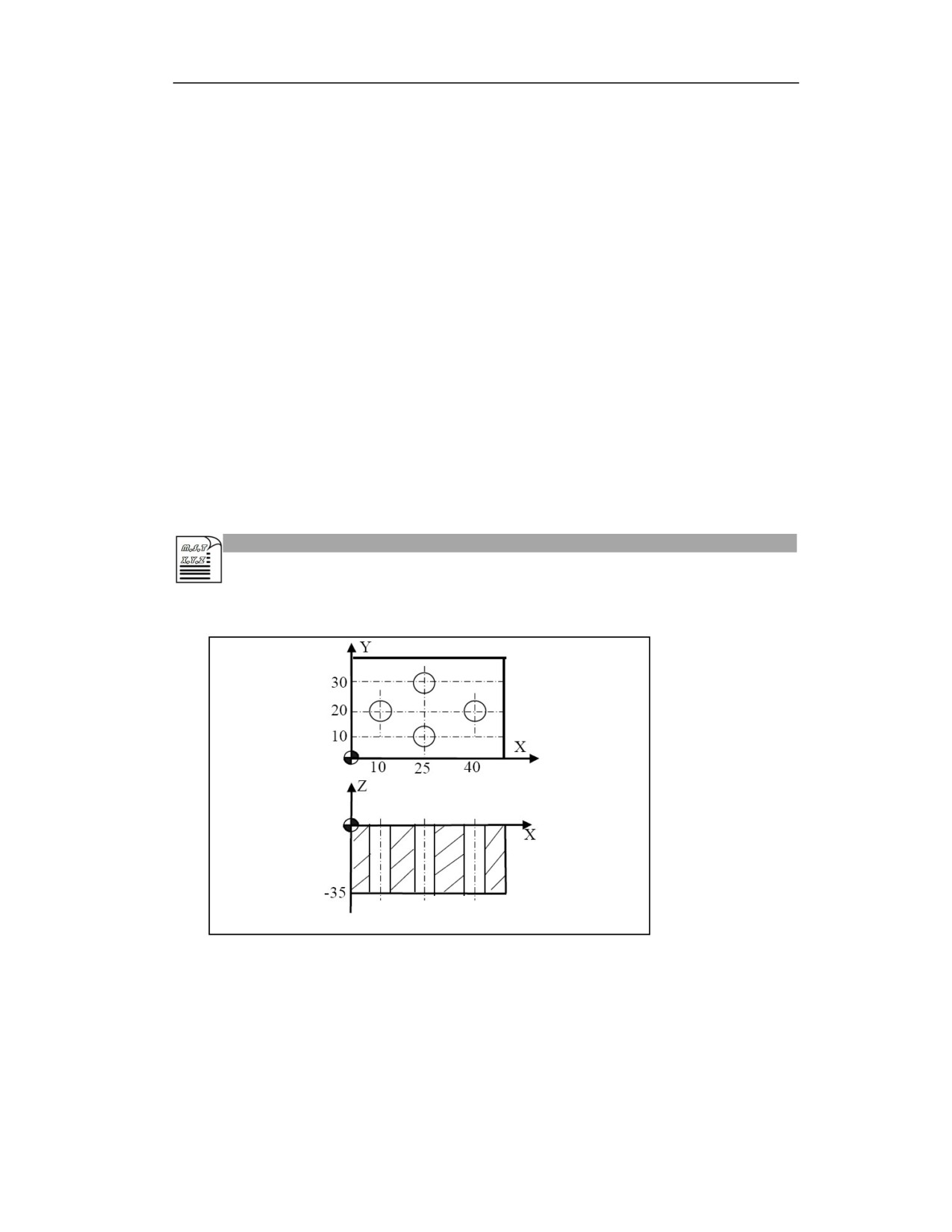
Example
Process the hole as shown below.
Example 1
%3343
G54G0 X0 Y0 Z30; Return to the safe height of workpiece zero
M03 S800; Spindle rotation CW
G0 Z10; Position to the initial level
G99 G83 X10 Y20 R5 Z-35 Q-1 K0.2 F200; Position to the hole (10 20), perform
23
drilling, return to R level
X25Y30; Position to the hole (25 30), perform drilling, return to R level
X40Y20; Position to the hole (40 20), perform drilling, return to R level
X25Y10; Position to the hole (25 10), perform drilling, return to R level
G80;Cancel drilling canned cycle
G28 G91 Z0; Return to machine zero of Z axis
G28 G91 X0 Y0; Return to machine zero of X axis and Y axis
M30; Program end;
Note
(1) Axis switching: please cancel canned cycle before switching drilling axis.
(2) Modality: G81 command data is stored as modal data, the same data can be omitted;
(3) Drilling: Drilling cannot be in the block that does not include X, Y, Z, R or any other additional
axis. If the moving position of Z is zero, the command is not executed;
(4) Cancel: Do not specify the G codes of group 01 (G00 to G03, etc.) in the G81 block. Otherwise,
G81 will be cancelled.
(5) Tool position offset: In the drilling canned cycle mode, the tool position offset is ignored.
(6) P: Please specify P in the block of drilling. If it is specified in a non-drilling block, it cannot
be stored as modal data.
(7) Q: Please specify Q in the block of drilling. If it is specified in a non-drilling block, it cannot
be stored as modal data.
15.8
Tapping Cycle (G84)
Function and Purpose
With this function, the tapping of spindle rotation CW can be realized. There are two types of
reverse tapping. One is the tapping cycle, that is, the tapping path goes directly from point R to
point Z at the bottom of the hole; the other is the peck tapping cycle, that is, repeated intermittent
feed is performed during the tapping process.
In the tapping cycle, when the spindle rotates clockwise in tapping, and reaches the bottom of the
hole, the spindle rotates counterclockwise and exits. During the tapping or exit process, the
spindle feeds a thread lead along the tapping axis for each revolution of the spindle, and the feed
relationship does not change even during acceleration and deceleration.
When the PWM spindle is used, the tapping spindle moves synchronously with the spindle, which
is referred to as following tapping; when the servo spindle is used, both the spindle motor and
servo motor work in the position control mode, and the tapping is performed via the interpolation
23
between tapping axis and spindle, which is referred to as the synchronous tapping. The
programming commands are the same for the following tapping and synchronous tapping.
Note that the pitch of the tap used for tapping should be consistent with that in the programming
15.8.1 Tapping Cycle(G84)
Command Format
(G98/G99)G84 X_ Y_ Z_ R_ P_ F_ L__J_;
Parameter
Meaning
The absolute position of the hole in absolute programming (G90), and the
X Y
distance from the current position to the hole position in incremental
programming (G91);
The absolute position of hole bottom in absolute programming (G90); the
Z
distance from hole bottom to R point in incremental programming (G91);
The absolute position of R point in absolute programming (G90); the distance
R
from R point to initial level in incremental programming (G91);
P
Dwell time at the hole bottom (unit: ms)
F
Thread lead
L
Number of repetitions (can be omitted when L=1)
J
J1 A-axis tapping; J2 B-axis tapping; J3 C-axis tapping
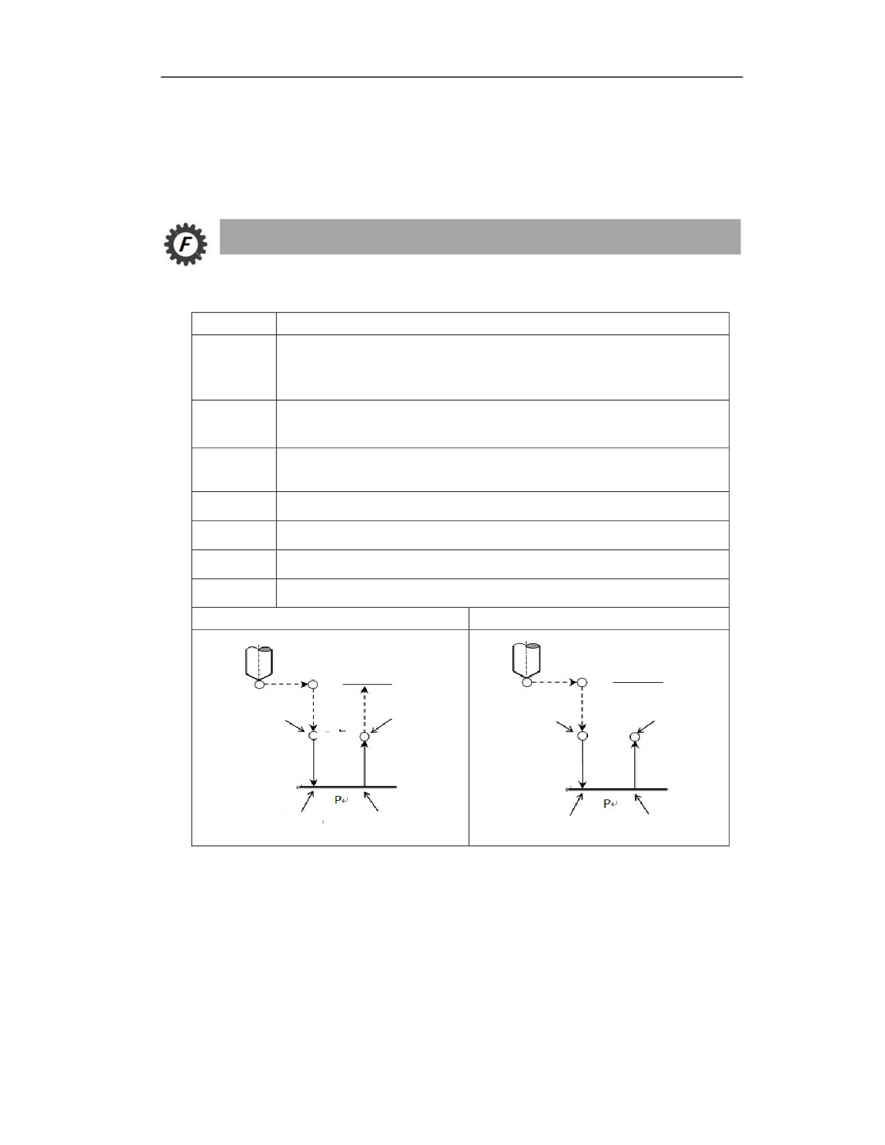
G84(G98)
G84(G99)
Initial level
Initial level
Spindle rotation CW
Spindle stop
Spindle rotation CW
Spindle stop
R point
R point
Z point
Z point
Spindle stop
Spindle rotation CCW
Spindle rotation CCW
Spindle stop
Action
(1) Rotate the spindle through the auxiliary function, and the tool position point will move to
point B above the hole center in rapid traverse;
(2) Spindle rotates CW, and approaches to the workpiece surface in rapid traverse, and reaches to
R point;
(3) System calculates feedrate base on the pitch speed; tap downward at the feedrate with the
depth of Z;
23
(4) Tap to the hole bottom, spindle stops;
(5) After the dwell time P is specified, pausing at hole bottom is performed;
(6) Spindle rotates CCW, tap upward in rapid traverse, retract to R point;
(7) Spindle stops;
(8) Retract upward to R point (G99) or B point (G98) in rapid traverse.
15.8.2 Peck Tapping Cycle (G84)
(G98/G99)G84 X_ Y_ Z_ Q_ K_R_ P_ F_ L_ E_J_
(peck tapping)
Parameter
Meaning
The absolute position of the hole in absolute programming (G90), and the
X Y
distance from the current position to the hole position in incremental
programming (G91)
The absolute position of hole bottom in absolute programming (G90); the
Z
distance from hole bottom to R point in incremental programming (G91)
Q
Feed amount
K
Retraction amount
The absolute position of R point in absolute programming (G90); the distance
R
from R point to initial level in incremental programming (G91);
P
Dwell time at the hole bottom (unit: ms)
F
Thread lead
L
Number of repetitions (can be omitted when L=1)
E
E1: peck tapping, feed Q, retract K
E2, peck tapping, feed Q, retract to R level
J
J1 A-axis tapping; J2 B-axis tapping; J3 C-axis tapping
Initial level
R point
R point
R point level
Z point
Z point
Peck tapping cycle action
(1) Rotate the spindle through the auxiliary function, and the tool position point will move to
23
point B above the hole center in rapid traverse;
(1) Spindle rotates CW; approaches to the workpiece surface in rapid traverse, and reaches to R
point;
(1) System calculates feedrate based on the pitch speed, tap downward at the feedrate with the
depth of Z;
(2) Spindle stops;
(3) After the dwell time P is specified, pausing at hole bottom is performed;
(4) Spindle rotates CCW; tap upward in rapid traverse, retract to R point;
(5) Spindle stops;
(6) Spindle rotates CW, tap downward at the feedrate with the depth of (times*Q)
(7) Repeat steps 4, 5, 6, 7, 8. Reach Z point at hole bottom;
(8) Dwell P ms at hole bottom (spindle keeps original rotation)
(9) Retract upward to R point (G99) or B point (G98) in rapid traverse.
Description
Spindle rotation
Before G84 is specified, the auxiliary function (M code) can be used to rotate spindle. The spindle
revolutions may affect the tapping speed.
Auxiliary function
When G84 and M code are specified in the same block, the M code is executed during the initial
positioning. When the number of repetitions L is specified, the above actions will only be executed
for the first time. The M code will not be executed after the second time.
Tool length compensation
When tool length compensation (G43, G44, G49) is specified in the drilling canned cycle, the
compensation is used when positioning to the R point.
Feedrate in tapping
During rigid tapping, the F (feedrate) specified in the program is invalid, and the feedrate along
the tapping axis is calculated by the following formula:
Feedrate = spindle speed × thread lead
Tapping mode
C-axis tapping: The servo spindle is used as the C-axis. High-speed and high-precision tapping
can be achieved using interpolation for tapping;
Example
23
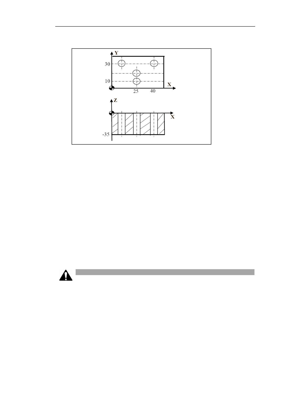
Process the hole as shown below.
Example 1
%3343
G54G0 X0 Y0 Z30; Return to the safe height of workpiece zero
M03 S3000; Spindle rotation CW
G0 Z10; Position to the initial level
G90G99 G84 X25 Y10 R5 Z-35P1000 F1; Position to the hole (25 10), perform
drilling, return to R level
X25Y20; Position to the hole (25 20), perform drilling, return to R level
X10Y30; Position to the hole (10 30), perform drilling, return to R level
X40Y30; Position to the hole (40 30), perform drilling, return to R level
G80; Cancel canned cycle;
G28 G91 Z0; Return to machine zero on Z axis
G28 G91 X0 Y0; Return to machine zero on X axis and Y axis
M30;Program end
Note
Axis switching: please cancel canned cycle before switching drilling axis.
Modality: G84 command data is stored as modal data, the same data can be omitted.
Drilling: Drilling cannot be in the block that does not include X, Y, Z, R or any other additional
axis. If the moving position of Z is zero, the command is not executed. Z point must be lower than
R level, otherwise an alarm will be issued.
Position mode G108 or STOC: Before the tapping command G84 is used, please switch the
spindle servo motor from the speed mode to the position mode by the STOC command. After the
tapping, user could switch the spindle servo motor from position mode to speed mode by CTOS
23

command, and use the servo spindle as the ordinary spindle.
Scaling and Rotation: the rotation or scaling are not supported in the process of rigid tapping.
Cancel: Do not specify the G codes of group 01 (G00 to G03, etc.) in the G84 block. Otherwise,
G84 will be cancelled.
Tool position offset: In the drilling canned cycle mode, the tool position offset is ignored.
P: Please specify P in the drilling block. If it is specified in the non-drilling block, it cannot be
stored as modal data.
Q: Please specify Q in the drilling block. If it is specified in the non-drilling block, it cannot be
stored as modal data.
Reset: when the reset is executed during rigid tapping, the rigid tapping mode cannot be released,
and the machine tool cannot stop tapping.
Emergency stop can be effective.
Feed hold, single block: In G84 (G74) mode, the feed hold will be executed after each tapping
action is completed, and the subsequent tapping will continue after pressing the cycle start button.
The feed hold is executed after each tapping action is completed in single block mode, and the
next tapping action will be completed after pressing the cycle start button.
Machine lock: machine lock is also effective to G84 (G74).
Even if G84 (G74) is executed in the machine lock state, the drilling axis will not move. Therefore,
the spindle will not move.
15.9
Boring Cycle (G85)
Function and Purpose
This cycle is for hole boring.
In the boring cycle, when the bottom of the hole is reached, the cutting feed is executed until tool
returns to the R point. If in G98 mode, the tool will quickly return to the initial level after reaching
R point.
Command Format
(G98/G99) G85 X_ Y_ Z_ R_ P_ F_ L_;
Parameter
Meaning
The absolute position of the hole in absolute programming, and the distance from
X Y
the current position to the hole position in incremental programming;
23
The absolute position of hole bottom in absolute programming (G90); the
Z
distance from hole bottom to R point in incremental programming (G91);
The absolute position of R point on Z in absolute programming (G90); the
R
distance from R point to initial level in incremental programming (G91);
P
Dwell time at the hole bottom (unit: ms)
F
Cutting feedrate
L
Number of repetitions (can be omitted when L=1)
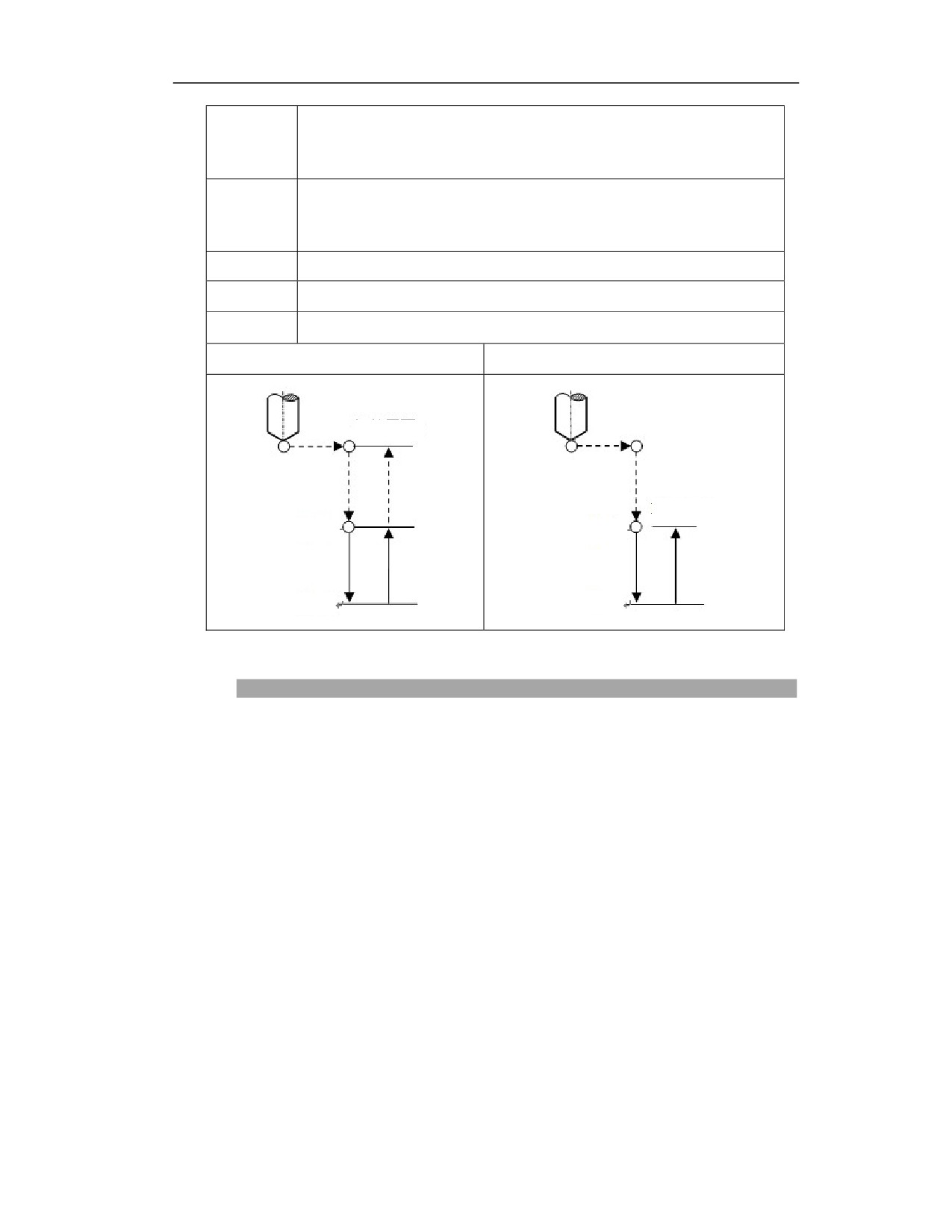
G85(G98)
G85(G99)
Initial level
R point level
R point
R point
Z point
Z point
Description
Boring cycle actions
(1)Tool position point moves to B point above hole center in rapid traverse;
(2)Move close to the workpiece surface, and reach to R point;
(3)Bore downward at F speed;
(4)Reach Z point at hole bottom;
(5)Retract upward to R point at F speed (spindle keeps rotating);
(6)Retract upward to B point in rapid traverse if in G98.
The drilling axis must be Z axis;
Z point must be lower than B level; otherwise, the alarm will be issued;
If the movement amounts of Z, Q, K are zero, then the command will not be executed;
G85 command data is stored as the modal data, and the same data can be omitted;
Please use corresponding M code to rotate spindle before G85 is used;
When G85 and M code are specified in the same block, the M code is executed at the
23