HNC8 Series CNC Controller. Programming Manual (V2.4) - page 5
Inside
Outside
Programmed path
Workpiece
Workpiece
Programmed path
Description
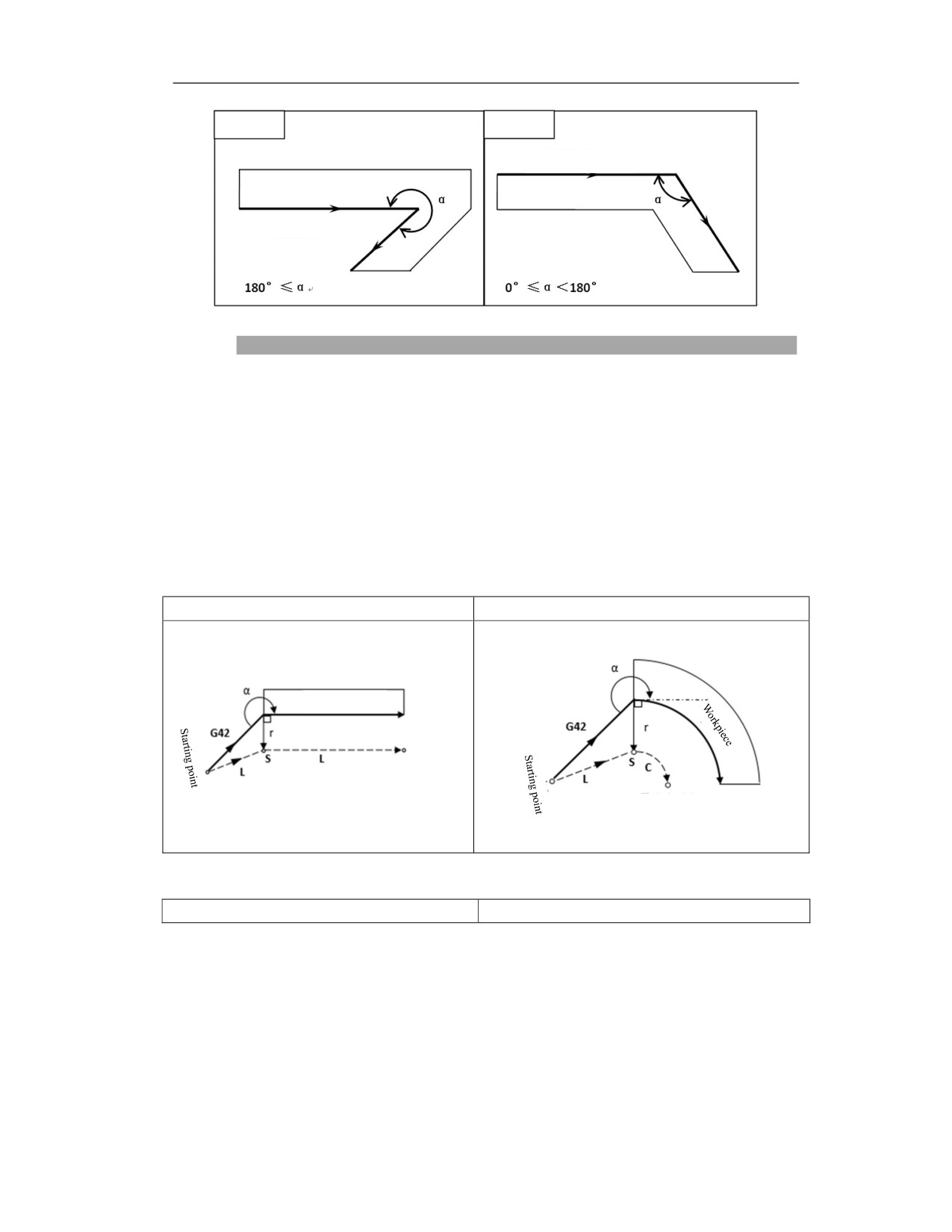
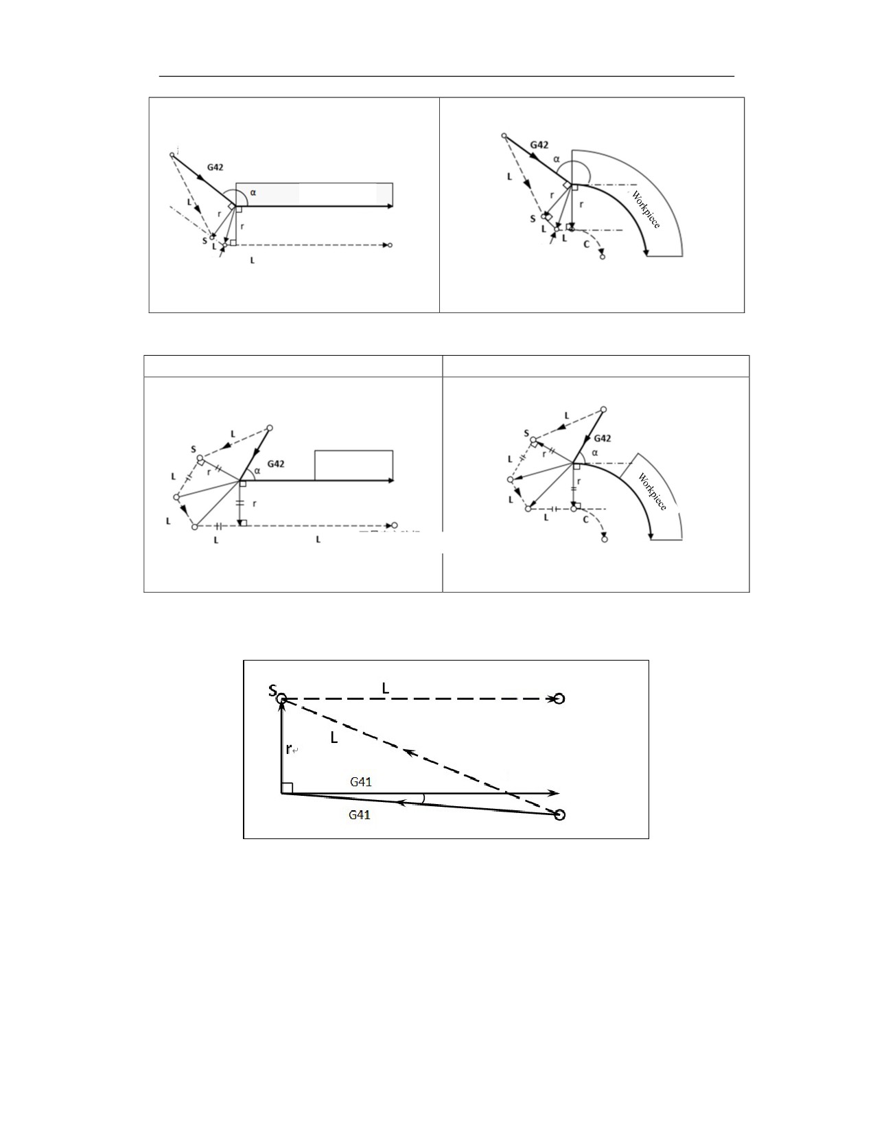
Action of tool radius compensation establishment and start
Meaning of sign
—S indicates that this position is the starting point for cutting.
—L indicates that the tool moves in a straight line.
—C indicates that the tool moves along an arc.
—r indicates tool radius compensation value.
(1) The tool moves around the inside of the corner (α≥180°)
Straight line→straight line
Straight line→arc
Workpiece
Programmed path
Tool center path
Programmed
Tool center path
path
(2) The tool moves around the outside of the corner (90°≤α<180°)
Straight line→straight line
Straight line→arc
16
Starting point
Starting point
Inside
Workpiece
Programmed path
Intersection
Intersection
Tool center path
Tool center path
Programmed path
(3) The tool moves around the inside of the corner(α<90°)
Straight line→straight line
Straight line→arc
Starting point
Starting point
Workpiece
Programmed path
Tool center path
Tool center path
Programmed path
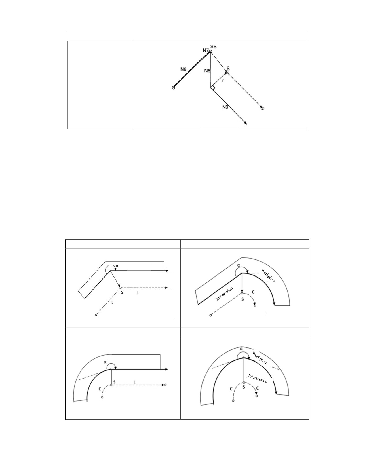
(4) The tool moves around the outside of the acute corner less than 1° (α<1°)
Straight line→straight line
Tool center path
Programmed path
Starting
Smaller than 1°
position
(5) There is no tool movement command in the starting block
If there is no tool movement command in the starting block, no offset is established.
16
G91 G40
N6 X100 Y100
N7 G41 X0
Tool center path
N8 Y-100
N9 Y-100 X100
Programmed path
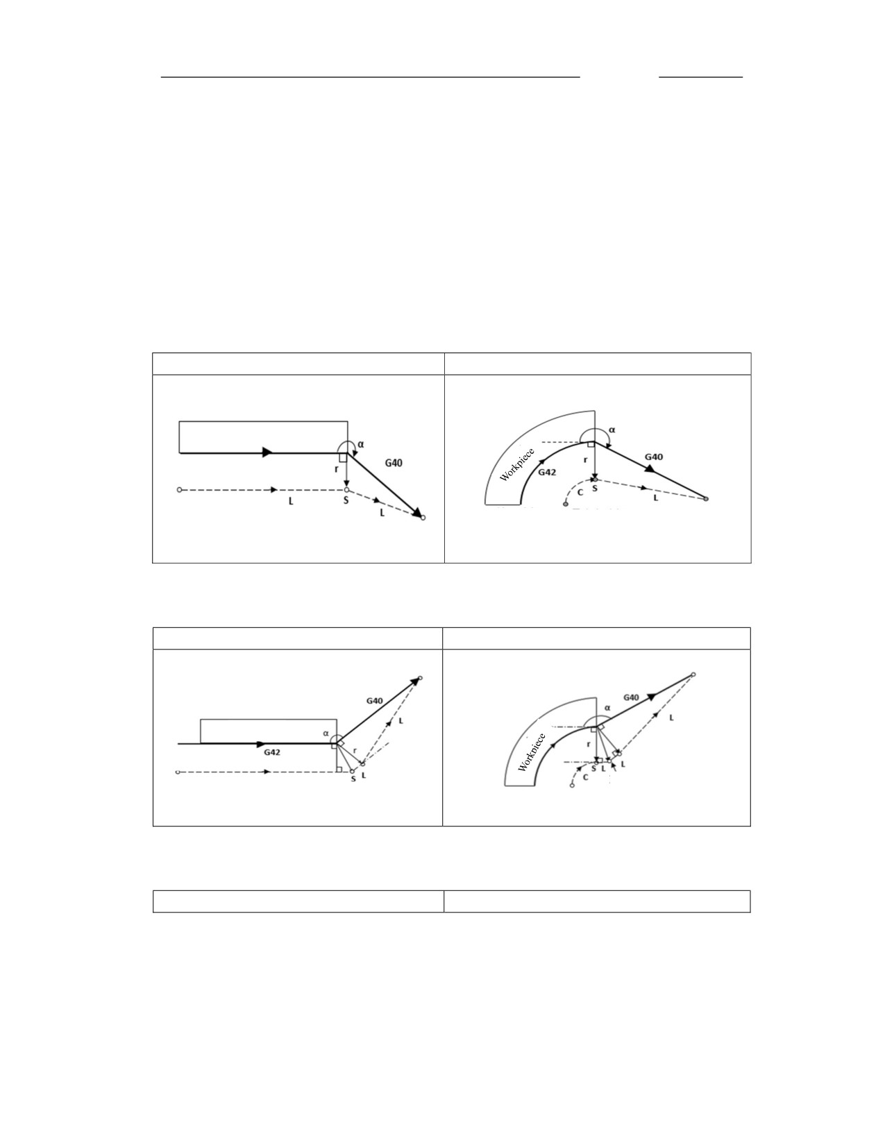
Action of tool radius compensation in progress
For the programmed path (G00, G01, G02, G03), the system calculates the tool path from a
straight line/arc, and performs tool radius compensation.
During the compensation, if the same compensation command (G41/G42) is specified, the second
compensation command will be ignored.
During compensation, if five blocks without movement are consecutively specified, overcutting
or undercutting will occur.
In tool radius compensation, when M00 is designated, read-ahead is prohibited.
(1)The tool moves around the inside of the corner (α≥180°)
Straight line→straight line
Straight line→arc
Workpiece
Programmed path
Tool center path
Intersection
Programmed path
Tool center path
Arc→straight line
Arc→arc
Workpiece
Programmed path
Intersection
Tool center path
Tool center path
Programmed path
(2)The tool moves around the outside of the corner (90°≤α<180°)
16
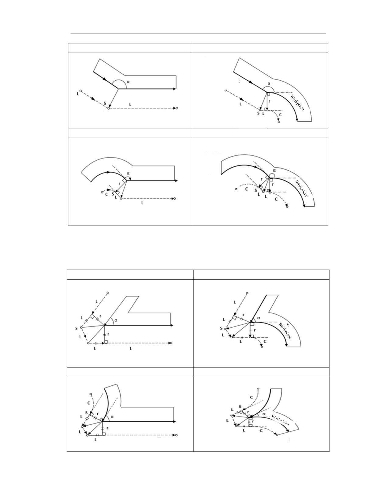
Straight line→straight line
Straight line→arc
Workpiece
Programmed path
Programmed path
Tool center path
Intersection
Tool center path
Intersection
Arc→straight line
Arc→arc
Workpiece
Programmed path
Programmed path
Tool center path
Intersection
Intersection
Tool center path
(3)The tool moves around the inside of the corner(α<90°)
Straight line→straight line
Straight line→arc
Workpiece
Programmed path
Tool center path
Tool center path
Programmed path
Arc→straight line
Arc→arc
Programmed path
Workpiece
Programmed path
Tool center path
Tool center path
16
Tool center path
mming Manual
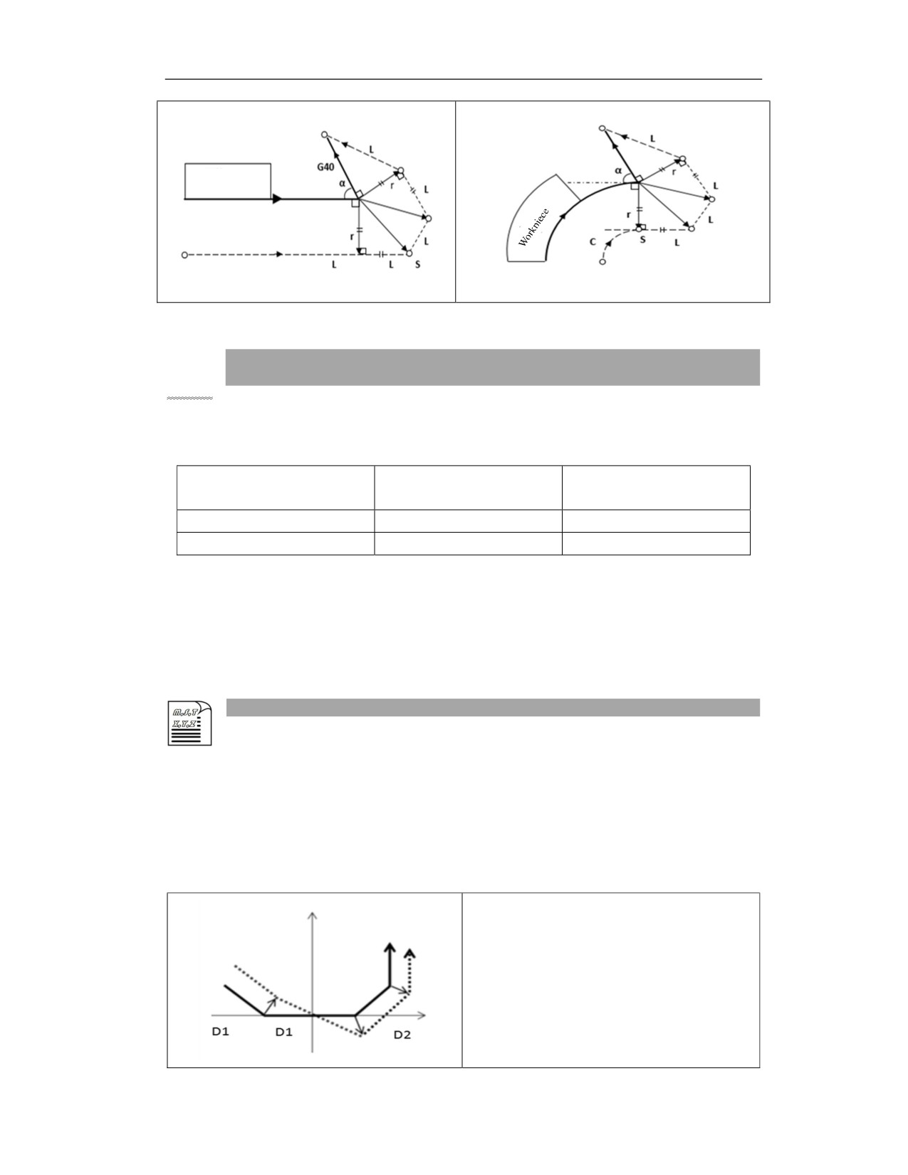
Action at the time of tool radius compensation cancellation
To cancel the tool radius compensation, there must be a movement command other than the
circular command. If the radius compensation is canceled in the circular command, the system
will issue an alarm.
When any of the following conditions is met, the tool radius compensation is cancelled.
a) G40 is executed.
b) Compensation number D00 is executed.
(1) In the block where there is movement cancellation, when the tool moves around the inside of
the corner (α≥180°)
Straight line→straight line
Straight line→arc
Workpiece
Programmed path
Tool center path
Programmed path
Tool center path
(2) In the block where there is movement cancellation, when the tool moves around the outside
of the obtuse angle (90°≤α<180°)
Straight line→straight line
Straight line→arc
Workpiece
Programmed path
Intersection
Tool center path
Intersection
Programmed path
Tool center path
(3) In the block where there is movement cancellation, when the tool moves around the outside
of the acute angle (α<90°)
Straight line→straight line
Straight line→arc
16
Workpiece
Programmed path
Tool center path
Tool center path
Programmed path
12.5.3 Compensation Direction Change During Tool Radius Compensation
Function and Purpose
The tool radius compensation direction is determined by the tool radius compensation command
(G41/G42) and the sign of the compensation value.
Tool radius compensation
Compensation value +
Compensation value -
command
G41
Compensation left
Compensation right
G42
Compensation right
Compensation left
The system does not support the use of G41 and G42 to change the compensation direction, and
an alarm "The tool compensation direction is not allowed to be changed during radius
compensation" will appear during use. It is not recommended to change the compensation
direction by changing the compensation sign during the compensation process, because different
programming compensation methods and use environments may result in different effects.
Example
Note: The following changes the compensation direction by changing the sign of the
compensation amount during the compensation process. Examples of programming will show the
following paths. (It is not recommended to use tool direction change).
The compensation direction is changed (straight line to straight line)
There is a path intersection when changing the compensation direction
%1234
G90G54G0X-50Y50
G41G01X-50Y20D1 (compensation value is
5)
X-30Y0
X30
X50Y20D2 (compensation value is -5)
Y50
16
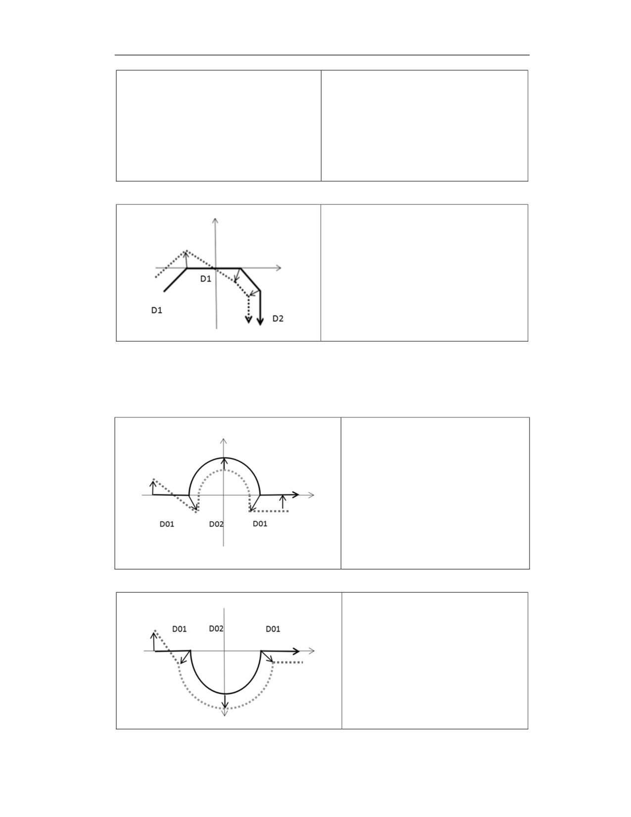
M30
There is no path intersection when changing the compensation direction
%1234
G90 G54 G0 X-60 Y-30
G41 G01 X-50 Y-20 D1 (compensation value
is 5)
X-30 Y0
X30 Y0
X50 Y-20 D2 (compensation value is -5)
Y-50
M30
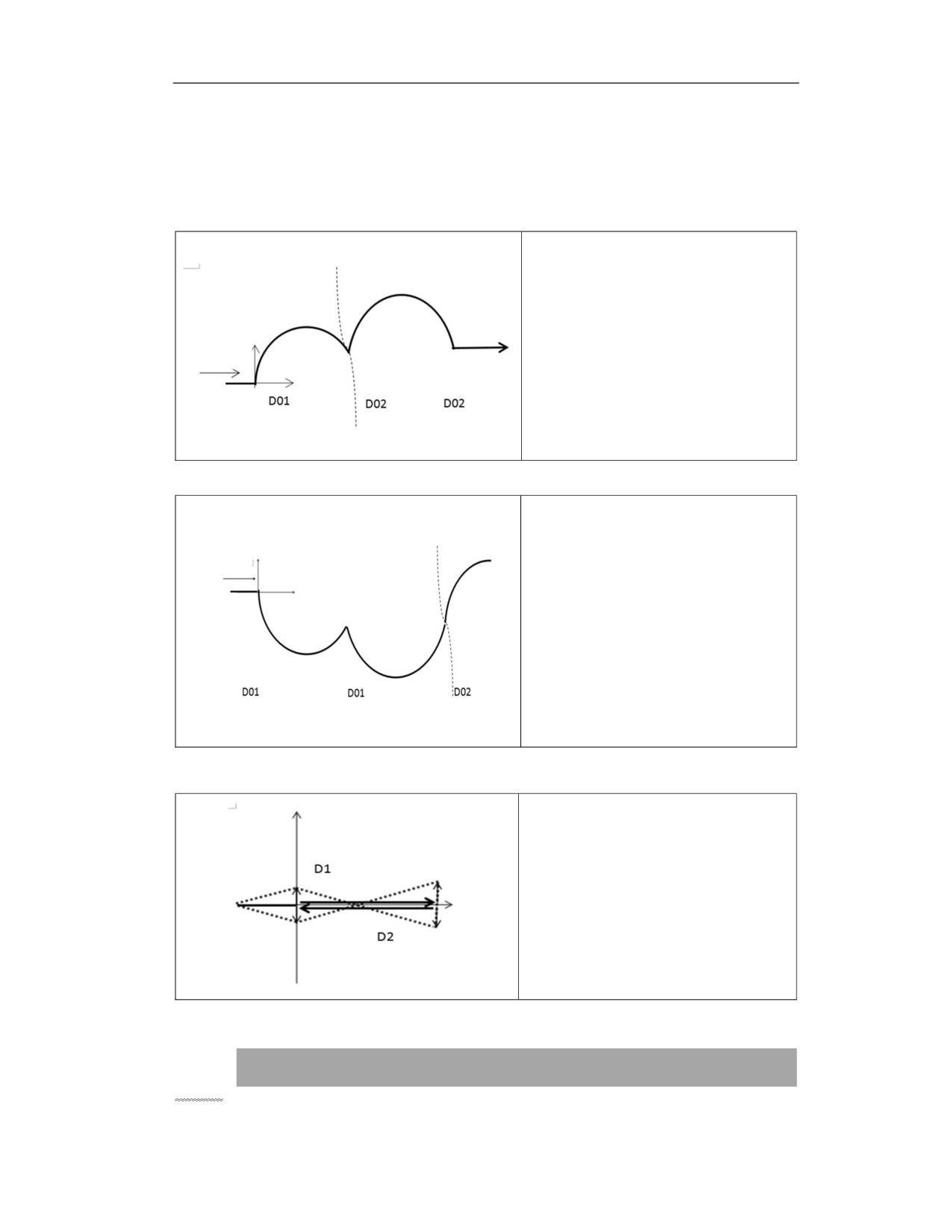
The compensation direction is changed in the way of (straight line to arc)
There is a path intersection when changing the compensation direction
%1234
G90 G54 G0 X-50 Y30
G41 G01 X-50 Y0 D1 (compensation
value is 5)
X-30 Y0
G2 X30 Y0 I30 J0 D2 (compensation
value is -5)
G1 X50 Y0 D1 (compensation value is 5)
G40
M30
There is no path intersection when changing the compensation direction
%1234
G90 G54 G0 X-50 Y30
G41 G01 X-50 Y0 D1 D1 (compensation
value is 5)
X-30 Y0
G3 X30 Y0 I30 J0 D2 (compensation
value is -5)
G1 X50 Y0 D1 (compensation value is 5)
M30
16
The compensation direction is changed (arc to arc)
Note: For the direction change programming for arc to arc, the system does not support the
following two programming methods.
There is a path intersection when changing the compensation direction
%1234
G90 G54 G0 X-50 Y0
G41 G01 X0 Y0 D1 (compensation
value is 5)
G2X53.64Y18.47I30J0
G41 feed
direction
X140.66Y0I41.55
J-18.47D2
(compensation value is -5)
G1X150
M30 This programming mode is not
supported for the direction change)
There is no path intersection when changing the compensation direction
%1234
G90 G54 G0 X-50 Y0
G41 feed
G41 G01 X0 Y0 D1 (compensation
direction
value is 5)
G3X18.02Y-4.04I9.03J1.7
X37.26Y-2.18I9.26 J3.7
G2X53.12Y10.61I13.99J-1.11D2
(compensation value is -5)
G1X50
M30 (This programming mode is not
supported for the direction change)
Linear reciprocating motion changes the direction of tool compensation vector
%1234
G90G54G0X-30Y0
G41G1X0Y0D1 (compensation value is
5)
X80
G01X0D2 (compensation value is -5)
G40 G01 X-30
M30
12.5.4 When Tool Radius Compensation is not Executed
Function and Purpose
16
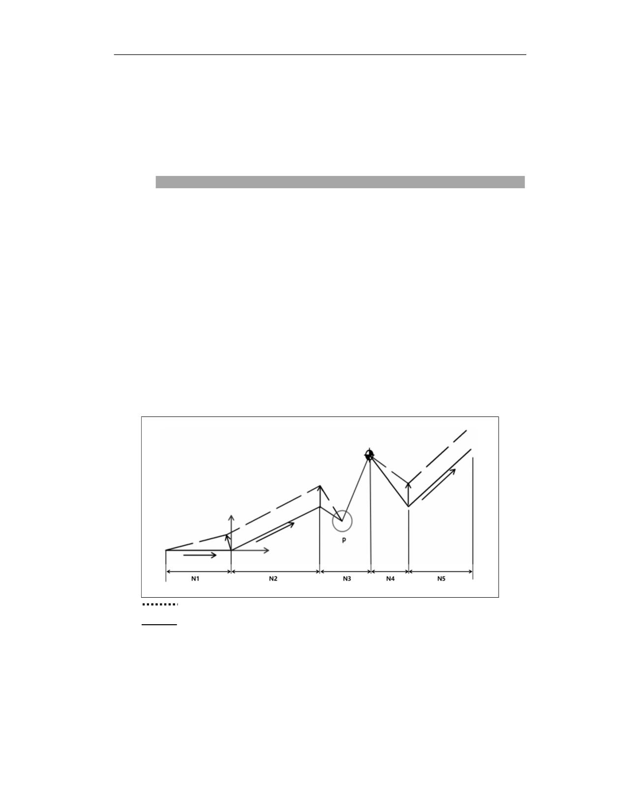
In radius compensation mode, when the commands (G28, G53) are executed, the compensation
vector will be temporarily invalid. After this type of command is executed, it will automatically
return to the compensation mode, and there is no need to cancel or add the compensation. The
point where the compensation vector is cancelled is the command point of the program. When the
compensation mode is restored, go directly to the command point and complete the restoration of
the compensation vector.
Description
(1) Reference point return command G28 in the radius compensation mode
At the intermediate point (there is no intermediate point when G91 is used, it is directly the
reference point), the compensation vector becomes 0
Example:%1234
G90G54G0X-30Y0
N1G41G1X0Y0D1
N2X40Y15
N3G28X50Y20
N4X80 Y30
N5X120 Y20
M30
Tool center path after compensation
Tool path when compensation is not executed
Point P is the position of the intermediate point at the time of reference point return. If there is no
intermediate point, it directly returns to the reference point.
(2) Direct machine coordinate system programming command G53 in radius compensation mode
In the G53 command (basic machine coordinate system selection), the compensation vector will
be temporarily cancelled.
16
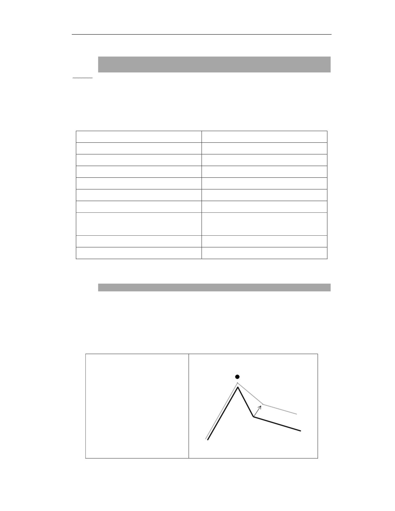
12.5.5 There is a Block without movement in Tool Radius Compensation
Function and Purpose
In the process of tool compensation creation and execution, the following 5 blocks will be read
ahead to establish the tool compensation path, so when there are continuous blocks without
movement in the program, the system will deal with it as follows.
The following blocks are regarded as non-moving blocks,
Non-moving block type
Example
M auxiliary code
M03/M04/M05/M06/M08
S speed command
S300
T tool number command
T6/Grouping T101
G04 dwell command
G04 X5/G04 P5000
Programmable data input block
G10 L10 P_
Coordinate system setting
G92 X0 Y0
The third axis movement command in the
G17 Z10
compensation plane
G code
G90/G94/G95/G08/G09/G64/G65
The movement amount is 0
G91 X0
M00, M01, M02, and M30 are treated as M codes of read-ahead prohibition.
Description
When starting to establish compensation,
At the beginning of the compensation establishment, there are more than 5 con
secutive blocks without movement and the read-ahead prohibition M command,
it does not affect the establishment of compensation.
%1234
G92X0Y0
Block without movement
G0 X30 Y60
command
G41 D1
G4X2
F1000
S500
M3
N1G1X20Y-50
X50Y-20
M30
16
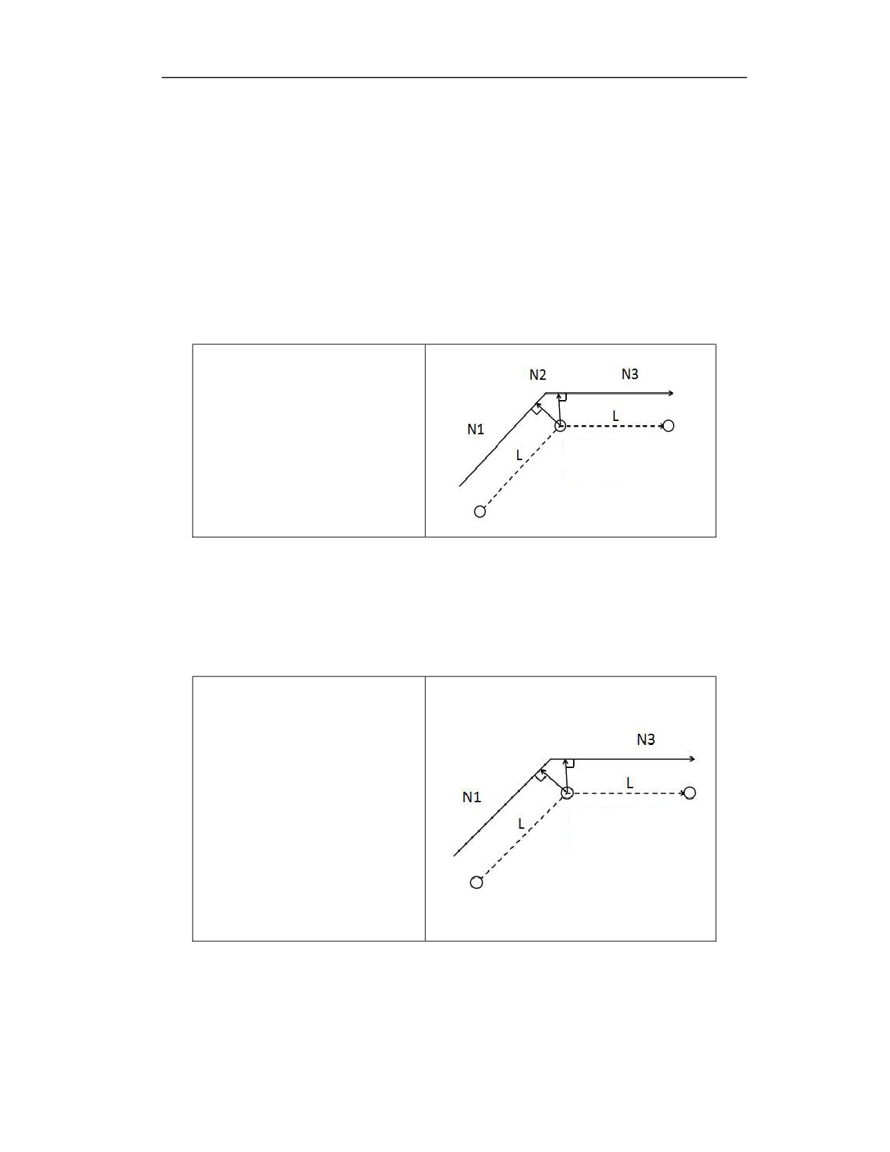
(Note 1) When G41 is used to establish tool compensation, there is no movement amount, and
there is no movement in 5 consecutive blocks. The tool compensation path is executed when the
block N1 is executed. At this time, the compensation path is not affected when the entire program
is creating tool compensation.
In the compensation mode
When there are no over 4 continuous blocks without movement, and there is no M command of
read-ahead prohibition in the compensation mode, the vector that the length equal to the
compensation value will be generated in the vertical direction of the movement direction of the
previous and next blocks. The non-movement block is executed at the vector stop point after
compensation.
%0001
G90G54G0X0Y-30
G42G01X0Y0D1
N1X30Y50
N2G04P1000
; Program block
The N2 block is executed
here
without movement
N3X80
……
Several blocks without tool movement should not be commanded continuously.
If there are more than 4 consecutive non-movement blocks, and the M commands of read-ahead
prohibition, a vector with a length equal to the compensation value will also be generated in the
vertical direction of the movement direction of the previous and next blocks, and the non-
movement block will stop at the vector point after the compensation.
%0001
G90G54G0X0Y-30
Block without movement
G42G01X0Y0D1
command
N1X30Y50
G04P1000
G91X0
Consecutive
non-
M3S300
movement blocks are
executed here.
F2000
M00
;Non-movement block
N3X80
……
Note: The block without movement in the figure means: execute the program between N1 and
N3.
The non-movement command is executed while the compensation is cancelled
17
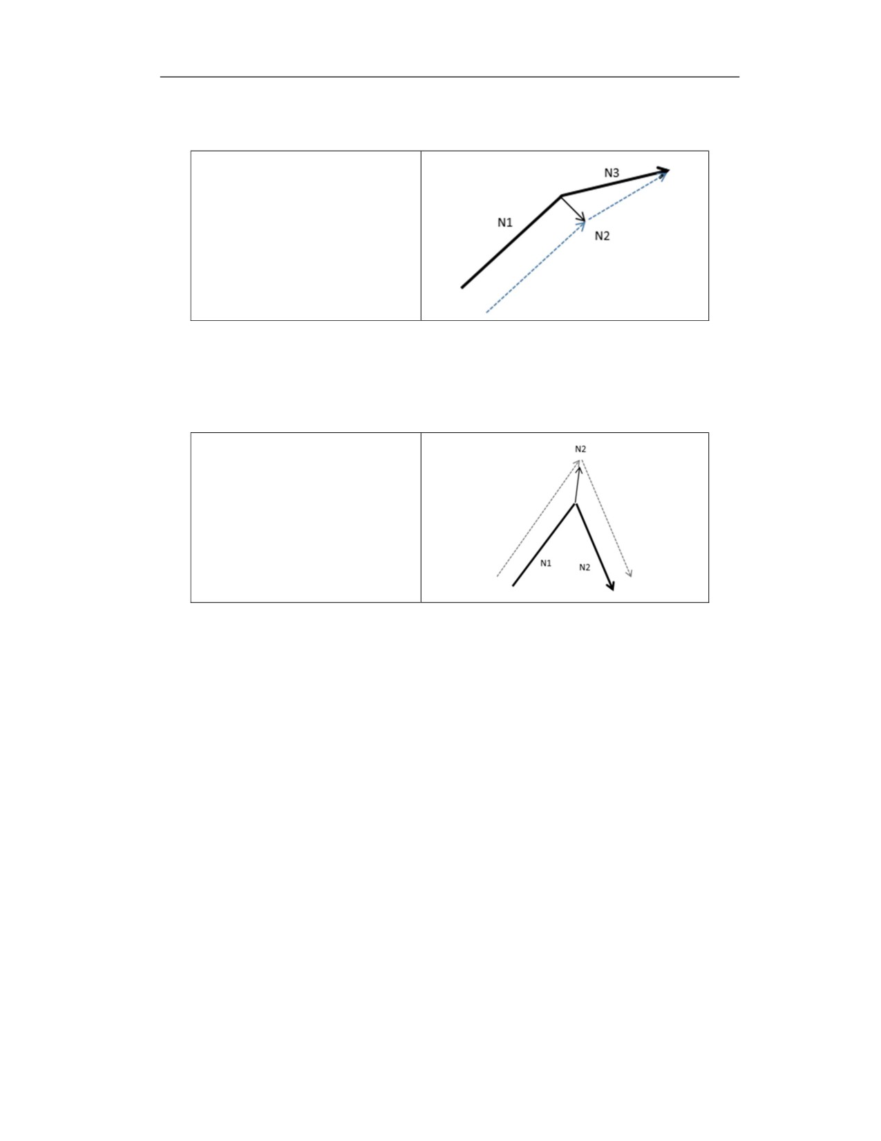
When the non-movement block and G40 command are executed at the same time, only the
compensation vector is cancelled.
%0001
G90G54G0X0Y-30
G42G01X0Y0D1
N1X30Y50
N2G40
;Non-movement block
N3X80Y30
12.5.6 Action Insertion in Tool Radius Compensation
MDI insertion command
1) Non-movement command is inserted in MDI (tool path will not change)
%0001
G90G54G0X0Y-30
G42G01X0Y0D1
N1X30Y50
N2
;Insert the execution of
M3S1000 in MDI
N3X55Y20
……
The MDI mode can be switched to only when the feed is held, so when running to the N1 block,
the single-block running mode is switched to, and after entering the feed hold, the MDI mode is
switched to for the insertion of a non-movement command.
2) Insert a movement command in MDI
The system runs the program of radius compensation in auto mode. If a movement command is
input in MDI and the position of the machine tool is changed when the program is paused, the
system will alarm that it is not at the breakpoint position when it returns to the program to run. It
can continue to run after resuming the breakpoint position, and the compensation is added
normally.
Manual insertion action
The system runs the program in radius compensation in auto mode. If each axis of the machine
tool is moved in JOG mode, and the position of the machine tool is changed when the program is
paused, the system will alarm that it is not at the breakpoint position when it returns to the program
to run. It can continue to run after resuming the breakpoint position, and the compensation is
added normally.
17
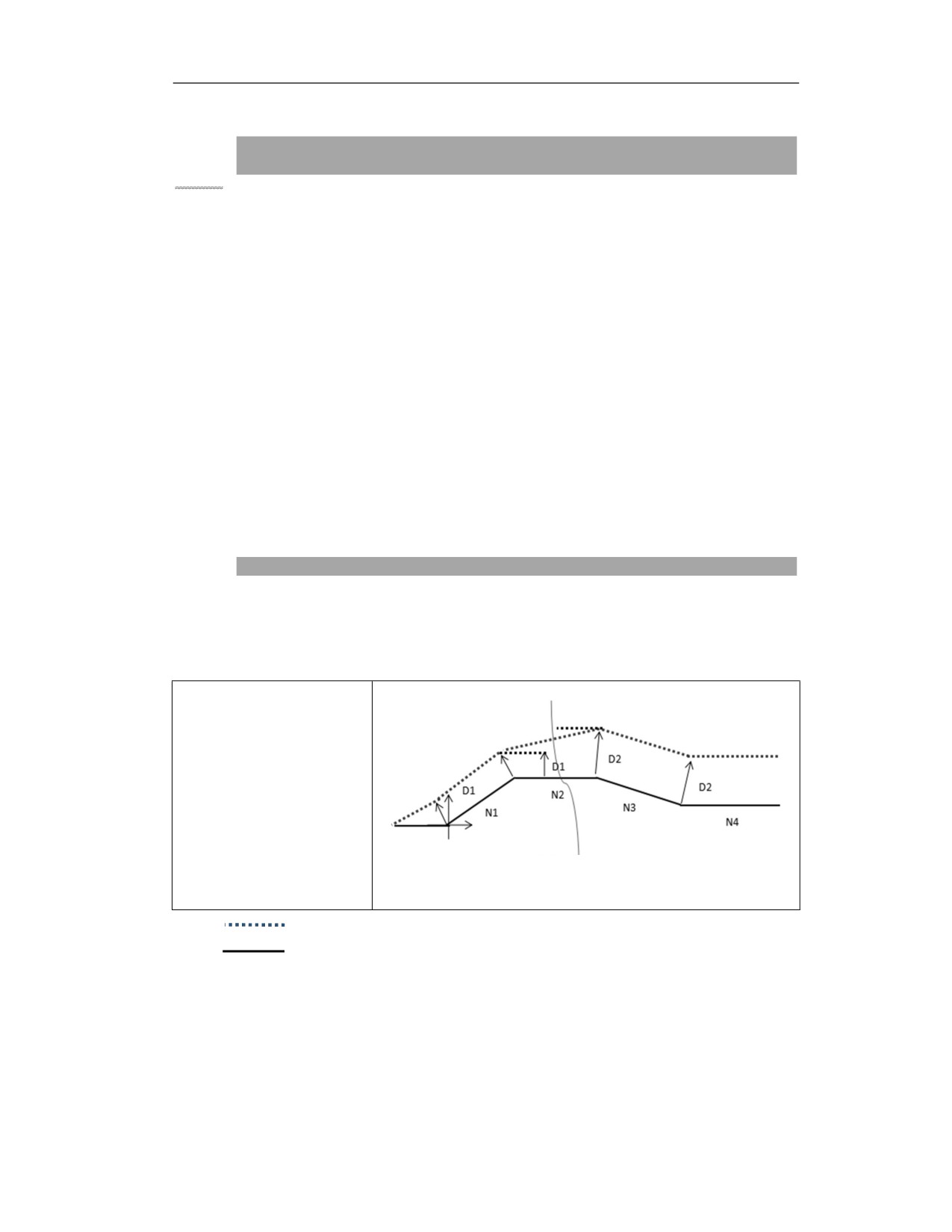
12.5.7 Change of Compensation Value in Tool Radius Compensation
Function and Purpose
In principle, do not change the compensation number randomly in the radius compensation mode.
Different compensation numbers may correspond to different compensation values, and the
programmed trajectory will also change. If the compensation number is changed, the following
actions are performed.
The program code format for changing compensation number is as follows,
G41G01……D(r1)
G0/G01/G02/G03 X_ Y_
G0/G01/G02/G03 X_ Y_
G0/G01/G02/G03 X_ Y_ D(r2) ; Compensation number is changed from r1 to r2
G0/G01/G02/G03 X_ Y_
……
Description
1) Path of straight line→straight line
The programmed path is an acute angle,
G90G54G0X-30Y0
G41G1X0Y0D01
(Compensation value is 5)
N1X20Y15
N2X40Y15
N3X60Y10D02
( Compensation value is
10)
This part is executed by D02
This part is executed by D01
N4X80
……
Tool center path after compensation
Tool path before compensation
The programmed path is an obtuse,
17
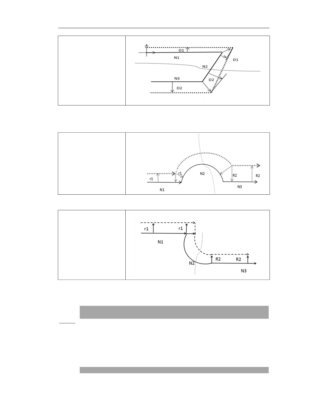
This part is executed by D01
G90G54G0X-30Y0
G41G1X0Y0D01
(Compensation value is 5)
N1X50Y0
N2X40Y-20
N3X-20D02(Compensation
value is 10)
……
This part is executed by D02
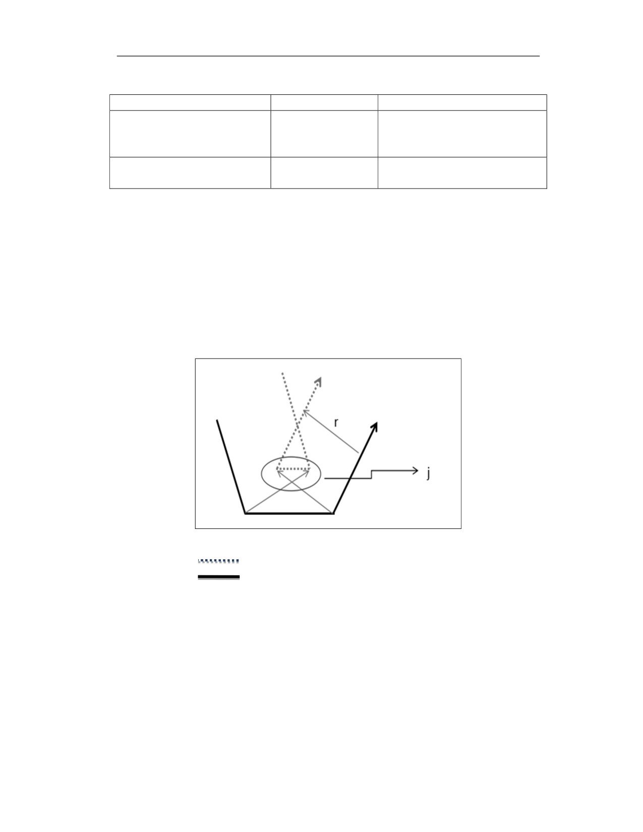
2) Path of straight line→arc
Change of compensation amount inside sharp corners
G90G54G0X-30Y0
This part is executed by D02
G41G1X0Y0D01
(Compensation value is 5)
N1X20Y0
This part is executed by D01
N2G2X60Y0I20J0D02
N3X90Y0 ( Compensation
value is 10)
……
Change of compensation amount outside the sharp corner
This part is executed by D01
G90G54G0X-30Y0
G41G1X0Y0D01
(Compensation value is 5)
N1X20Y0
This part is executed by D02
N2G3X40Y-20I20J0D2
N3X90
( Compensation
value is 10)
……
12.5.8 Interference Check
Function and Purpose
Usually, the overcutting of tool may occur after program read-ahead and tool radius compensation,
which is referred to as interference. The interference check function can check the tool overcut in
advance (even if there is no overcut, the interference check is performed). However, this function
cannot find out all interference.
Description
17
There are two modes for interference check via parameter setting.
Function
Parameter
Action
Before the overcut interference occurs
Interference
alarm
Interference check alarm function
during the compensation, the system
control Enable
will alarm and stop running
Auto
correct
The path is changed to avoid overcutting
Interference check avoidance function
interference Enable
Note: When parameter 010046 is set to 0, the interference alarm function is turned on.
When parameter 010046 is set to 1, the auto interference correction function is turned on.
When parameter 010047 (number of radius compensation interference check blocks) is set to 4,
3 blocks is read ahead for check interference.
As the compensation interference condition
In the pre-reading
4 blocks, when there are movement commands in 3 blocks, and the
compensation calculation vector on each movement command contact crosses the compensation
path, it is regarded as the interference.
r: compensation amount
j: the position the cross vector occurs
Tool center path after compensation
Tool path before compensation
Two modes are set to run the program with interference, the specific situations are as follows:
Example 1: use a tool with a larger diameter to process a parts containing a sharp corner
and a line segment
17
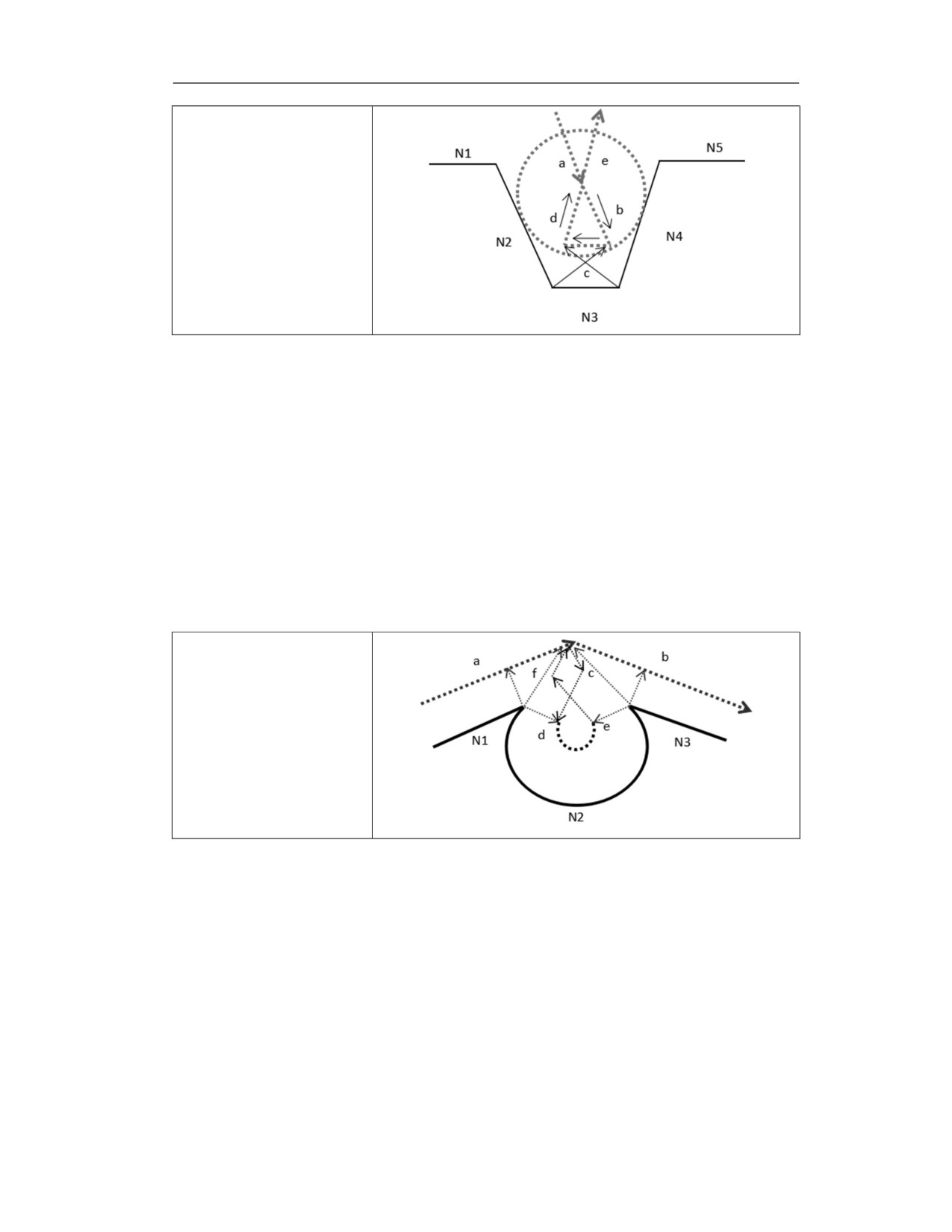
Left compensation
G90G54G0X-30Y0
N1G01G41X0Y0F1000
N2G01G41X20Y-30F1000
N3X30
N4X50Y0
……
1) Interference alarm
When parameter 010046 is set to 0, the interference alarm function is turned on. The parameter
010047 is set to 4 by default; When executing the above program, if an alarm is issued before N1
block, system stops running.
2) Interference avoidance
The intersection calculation of N2 and N4 blocks is executed, the interference avoidance vector
is created, the compensation path is automatically corrected, and the path is corrected to the a-e
path.
Example 2: Use a tool with a larger diameter to process the parts containing an arc of a
smaller radius
Left compensation
G90G54G0X_Y_
N1G01G41X_Y_F1000
N2G01X_Y_F1000
N3G2X_Y_I_J_
N4X_Y_
……
1) Interference alarm
When parameter 010046 is set to 0, the interference alarm function is turned on. The parameter
010047 is set to 4 by default; When executing the above program, if an alarm is issued before N1
block, system stops running.
2) Interference avoidance
Through the interference check processing, due to the path crossing occurs at points c and f, the
intersection calculation of N1 and N3 blocks is executed, the interference avoidance vector is
created, the compensation path is automatically corrected, and the path is corrected to the a-b path.
17
13 Programmable Data Input(G10/G11)
13.1
Programmable Data Input Command(G10/G11)
Function and Purpose
Through G10/G11 command, user can dynamically modify system data in the program. G10 is a
modal command. When G10 is specified, the programming data input mode can be entered, and
the modified system data will take effect in time. When G11 command is called, this mode is
cancelled.
The function list is as follows:
Function
G code
Input G54~G59 workpiece coordinate system origin
G10 L2 Pp IP_
Input G54.X extended workpiece coordinate system origin
G10 L20 Pp IP_
System parameter output
G10 L53 PpRr
Cancel user-defined input
G11
Milling tool geometry compensation value (length
G10 L10 PpRr
compensation) H input
Milling tool geometry compensation value (radius
G10 L12 PpRr
compensation) D input
Turning tool offset data input
G10 L14 Pp X_ Z_ R_ Q_ Y_ J_ K_
Single cutting time input
G10 L78 Pp
13.2
Workpiece Coordinate System Origin Input
Function and Purpose
According to the G10 command, the workpiece zero point (G54 to G59) offset can be set/changed
from the beginning of the program. In the absolute (G90) mode, the specified compensation
amount becomes the new compensation amount; in the incremental (G91) mode, the currently set
compensation amount is added to the specified compensation amount to become the new
compensation amount.
Command Format
G10 L2 Pp_ IP_
Parameter
Meaning
Pp
To specif the workpiece origin offset of the workpiece coordinate systems 1-6.
17
1 corresponds to G54 workpiece coordinate system
2 corresponds to G55 workpiece coordinate system
3 corresponds to G56 workpiece coordinate system
4 Corresponds to G57 workpiece coordinate system
5 corresponds to G58 workpiece coordinate system
6 corresponds to G59 workpiece coordinate system
The workpiece origin offset of axis in absolute mode.
IP
It will be added to the original offset of the workpiece origin of axis in
incremental mode.
Example
%1002
G54 ; G54 initial value
G01X0Y0Z0
G90G10L2P1X100Y100Z100 ; G54 workpiece coordinate system zero is changed to
(100,100,100) in absolute mode.
G11
G01X20Y20Z20 ; The command value of the machine coordinate system is (120, 120,
120)
G91G10L2P1X50Y50Z50
; G54 workpiece coordinate system zero is changed to
(150,150,150) in incremental mode.
G11
G90G01X20Y20Z20 ; The command value of the machine coordinate system is (170, 170,
170)
M30
13.3
Extended Workpiece Coordinate System Origin Data Input
Function and Purpose
According to the G10 command, the offset of the extended workpiece coordinate system (G54.1
to G54.60) can be set/changed from the beginning of the program. In the absolute (G90) mode,
the specified compensation amount becomes the new compensation amount; in the incremental
(G91) mode, the currently set compensation amount is added to the specified compensation
amount to become the new compensation amount.
Command Format
G10 L20 Pp_ IP_
Parameter
Meaning
17
The specified code p of the workpiece coordinate system of the
Pp
workpiece origin offset value: 1 to 60, corresponding to the X
value in the G54.X coordinate system;
The workpiece origin offset of axis in absolute mode; It will be
IP
added to the original offset of the workpiece origin of axis in
incremental mode.
Example
%1003
G54 ; G54 initial value
G01X0Y0Z0
G90G10L20P1X50Y50Z50 ; G54.1 workpiece coordinate system zero is changed to
(50,50,50) in absolute mode.
G11
G01X20Y20Z20 ; The command value of the machine coordinate system is (70, 70, 70)
G91G10L20P1X50Y50Z50 ; G54.1 workpiece coordinate system zero is changed to
(100,100,100) in incremental mode.
G11
G90G01X20Y20Z20 ; The command value of the machine coordinate system is (120, 120,
120)
M30
13.4
System Parameter Data Output
Function and Purpose
System parameters is output to the current channel variable specified by Rr, #0~#49
Command Format
G10 L53 Pp__Rr_
Parameter
Meaning
Pp
Parameter ID index number
Rr
Variable address(#0~#49)
Example
17
%1004
G54
G01X0Y0Z0
G10L53P010340R1
; Read the value of machine user parameter 010340 and assign it to
variable #1
G10L53P010341R2
; Read the value of machine user parameter 010341 and assign it to
variable #2
G11
M30
13.5
Milling Tool Length Compensation Data Input
Function and Purpose
With the G10 command, the milling tool length compensation can be set or changed in the
program. In the absolute (G90) mode, the specified compensation amount becomes the new
compensation amount; in the incremental (G91) mode, the currently set compensation amount is
added to the specified compensation amount to become the new compensation amount.
Command Format
G10 L10 Pp_ Rr_
Parameter
Meaning
Pp
Tool offset number
Rr
Tool compensation data
Example
%0005
G54
G01X100Y100Z100
G90G10L10P1R2 ;No.1 tool length compensation is changed to 2 in absolute mode
G11
G43Z50H1 ;H1=2
G49Z0
G91G10L10P1R8 ;No.1 tool length compensation is changed to(8+2=10)in incremental
mode
G11
G90G43Z50H1 ;H1=10
G49Z0
17
M30
Note
If the tool length compensation is changed with G10, the tool length compensation needs to be
called again with G43 or G44 to take effect.
13.6
Milling Tool Radius Compensation Data Input
Function and Purpose
With the G10 command, the milling tool radius compensation can be set or changed in the
program. In the absolute (G90) mode, the specified compensation amount becomes the new
compensation amount; in the incremental (G91) mode, the currently set compensation amount is
added to the specified compensation amount to become the new compensation amount.
Command Format
G10 L12 Pp Rr
Parameter
Meaning
Pp
Tool offset number
Rr
Tool compensation data
Example
%0006
G54
G01X100Y100Z100
G10L12P2R1 ;No.2 tool radius compensation is changed to 1 in absolute mode
G11
G41X20Y20D2 ;D2=1
X30
G40X0Y0
G91G10L12P2R1 ; No.2 tool radius compensation is changed to (1+1=2) in incremental
mode
G11
G90G41X20Y20D2 ;D2=2
X30
G40X0Y0
M30
18
Note
If the tool radius compensation is changed with G10, the tool radius compensation needs to be
called again with G41 or G42 to take effect.
13.7
Lathe Tool Offset Data Input
Function and Purpose
With the G10 command, the lathe tool compensation, wear, tool nose offset can be set or changed.
In the absolute (G90) mode, the specified compensation amount becomes the new compensation
amount; in the incremental (G91) mode, the currently set compensation amount is added to the
specified compensation amount to become the new compensation amount.
Command Format
G10 L14 Pp X_ Z_ R_ Q_ Y_ J_ K_
Parameter
Meaning
Pp
Tool offset number
X
Tool compensation data X
Z
Tool compensation data Z
R
Tool nose radius compensation value R
Q
Imaginary tool nose direction
Y
Tool compensation data Y
J
Tool radial wear J
K
Tool axial wear K
Example
Modify the tool offset data of No. 1 in the tool offset table (for example, X axis offset is -100, Z
axis offset is -50, tool nose radius is 0.2, tool nose position number is 3) and call this tool offset:
%1007
G10L14P1X-100Z-50R0.2Q3
G11
T0101
……
M30
18
13.8
Get and Modify Single Cutting Time
Function and Purpose
The single cutting time on the main processing interface can be modified with G10L78.
Description
P parameter specifies the modified single processing time, unit: second
After modifying the "single cutting time", the "this cutting time" and "cumulative cutting time"
are updated simultaneously.
Example
%0008
G54
G01X100Y100Z100
G10L78P60; The single cutting time is changed to 60S
G10L78P1000; The single cutting time is changed to 1000S
G11
M30
Note
#1471: The current "single cutting" time can be read, but it is best to add G08 command to pause
the read-ahead, otherwise the read time may not be accurate;
18

14 Standard Canned Cycle of Lathe(T)
14.1
Simple Cycle of Lathe
There are five simple cycles for lathe system,
G
Function
command
G80
Innter (outer) diameter cutting cycle
G81
End face cutting cycle
G82
Thread cutting cycle
G74
End face deep-hole drilling cycle
G75
Outer diameter grooving cycle
For the cycle in this chapter, a G code block is used to complete the processing operation of
multiple block commands, so that the program can be simplified
Note
1) The cycles described in this chapter can only be used for lathe system.
2) The command format cannot be used for FANUC system.
14.1.1 Inner (Outer) Diameter Cutting Cycle
Function and Purpose
With this function, the operation control of 4 linear trajectories can be realized through one block.
The trajectory starts from the starting point A, and returns to the starting point A by
A→B→C→D→A, and finally completes a simple cycle processing, in which the the first and the
forth trajectories are the rapid traverse movements, and the second and the third trajectories are
movements at processing speed. The trajectories are shown in the figure below.
This function is suitable for simple inner or outer diameter cutting cycle.
1. Inner/Outer diameter cutting cycle of cylindrical surface
18
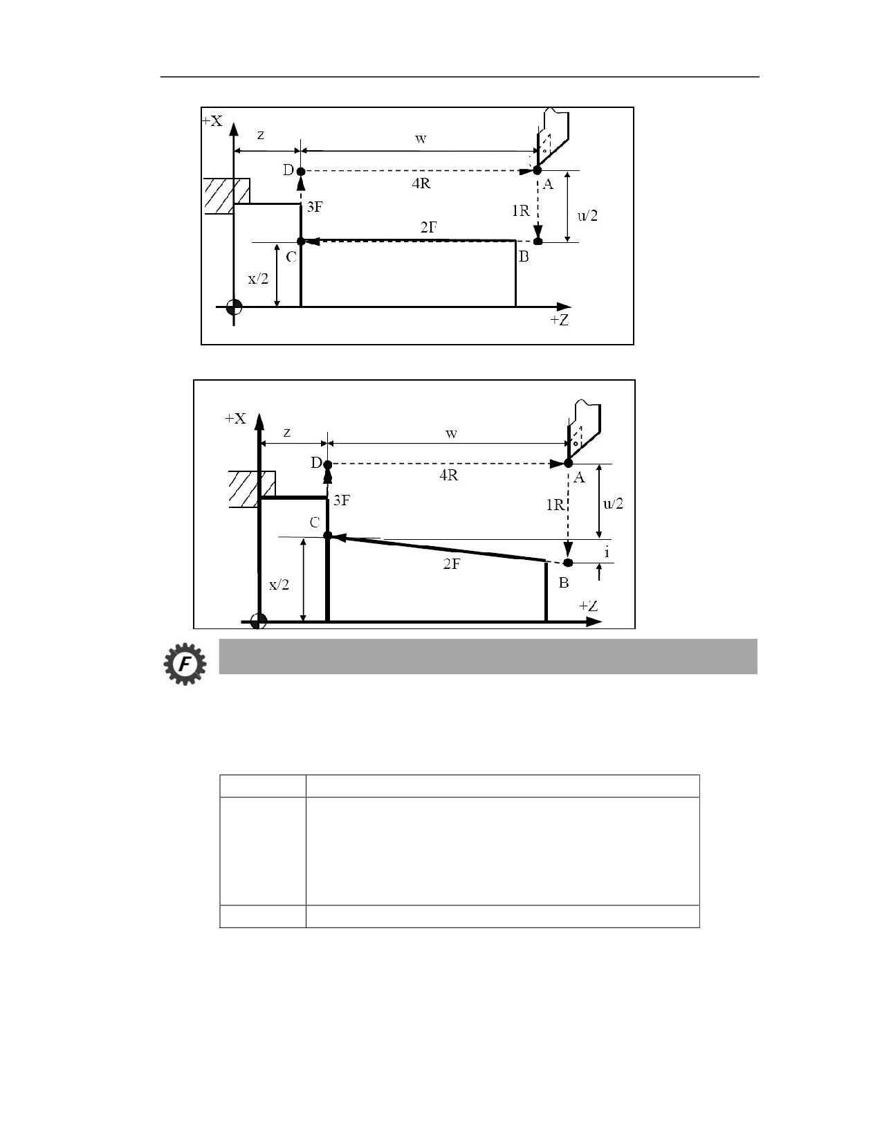
Tool retraction point
Cycle start point
Cutting end point
Cutting start point
2. Inner/Outer diameter cutting cycle of conical surface
Command Format
1. Inner/Outer diameter cutting cycle of cylindrical surface
G80 X_/U_ Z_/W_ F_
Parameter
Meaning
X/U Z/W
The coordinates of end point C in workpiece coordinate system in
absolute mode; the directional distance from cutting end pint C to the
cycle start point A in incremental mode, which is represented in U
and W in the diagram, and the sign is determined by the directions of
path 1 and path 2.
F
Feedrate (mm/min)
2. Inner/Outer diameter cutting cycle of conical surface
G80 X_/U_ Z_/W_ I_F_
18
Parameter
Meaning
X/U Z/W
The coordinates of end point C in workpiece coordinate system in
absolute mode; the directional distance from cutting end pint C to the
cycle start point A in incremental mode, which is represented in U and W
in the diagram, and the sign is determined by the directions of path 1 and
path 2.
I
The radius difference between the cutting start point B and the cutting
end point C (the sign of I determines the reverse taper or the forward
taper).
F
Feedrate (mm/min)
Example
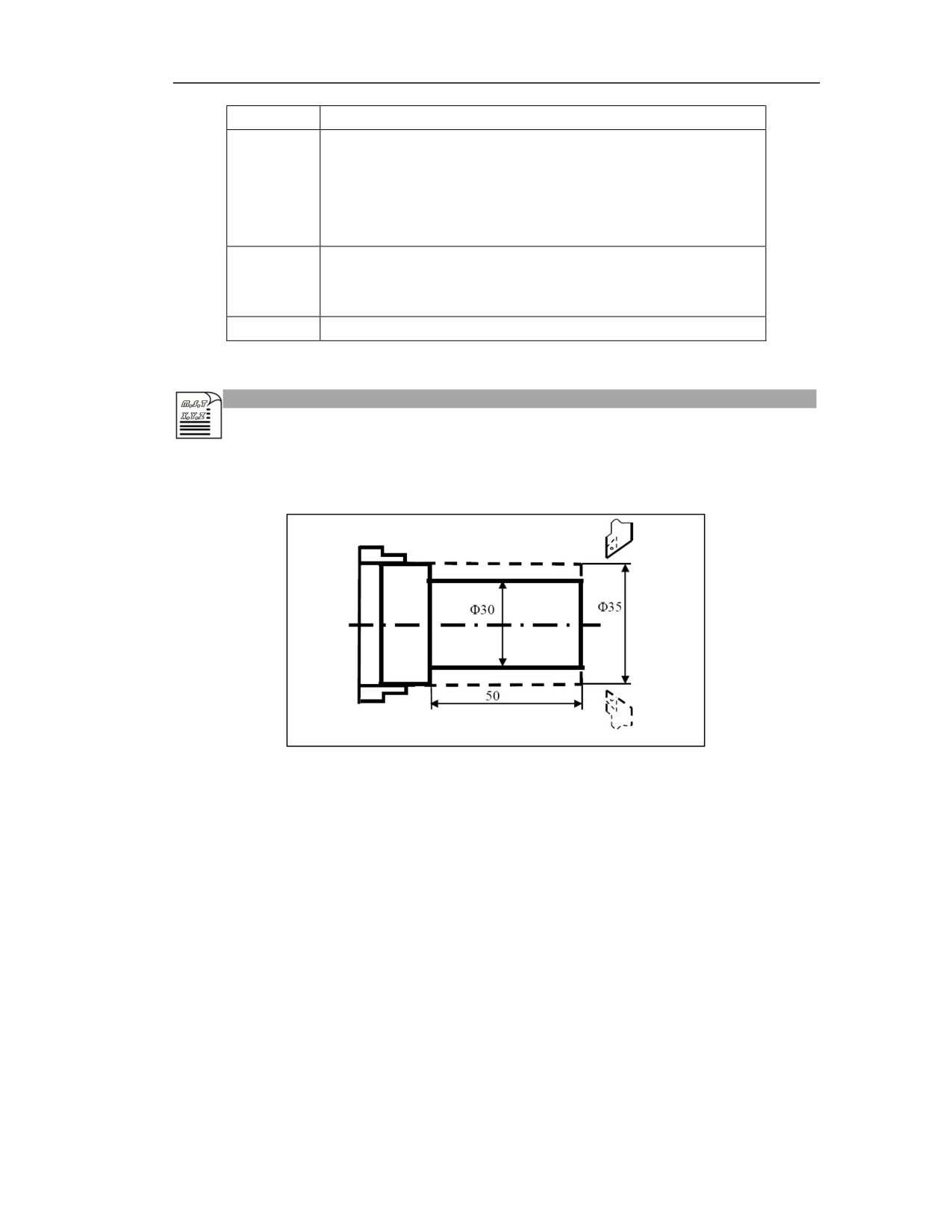
Example 1: Machining the workpiece as shown in the figure below with G80 command to rough and
finish simple conical parts.
%3320
N1 T0101
N2 M03 S460
N3 G00 X90Z20
N4 X40 Z3
N5 G80 X31 Z-50 F100
N6 G80 X30 Z-50 F80
N7 G00X90 Z20
N8 M30
18
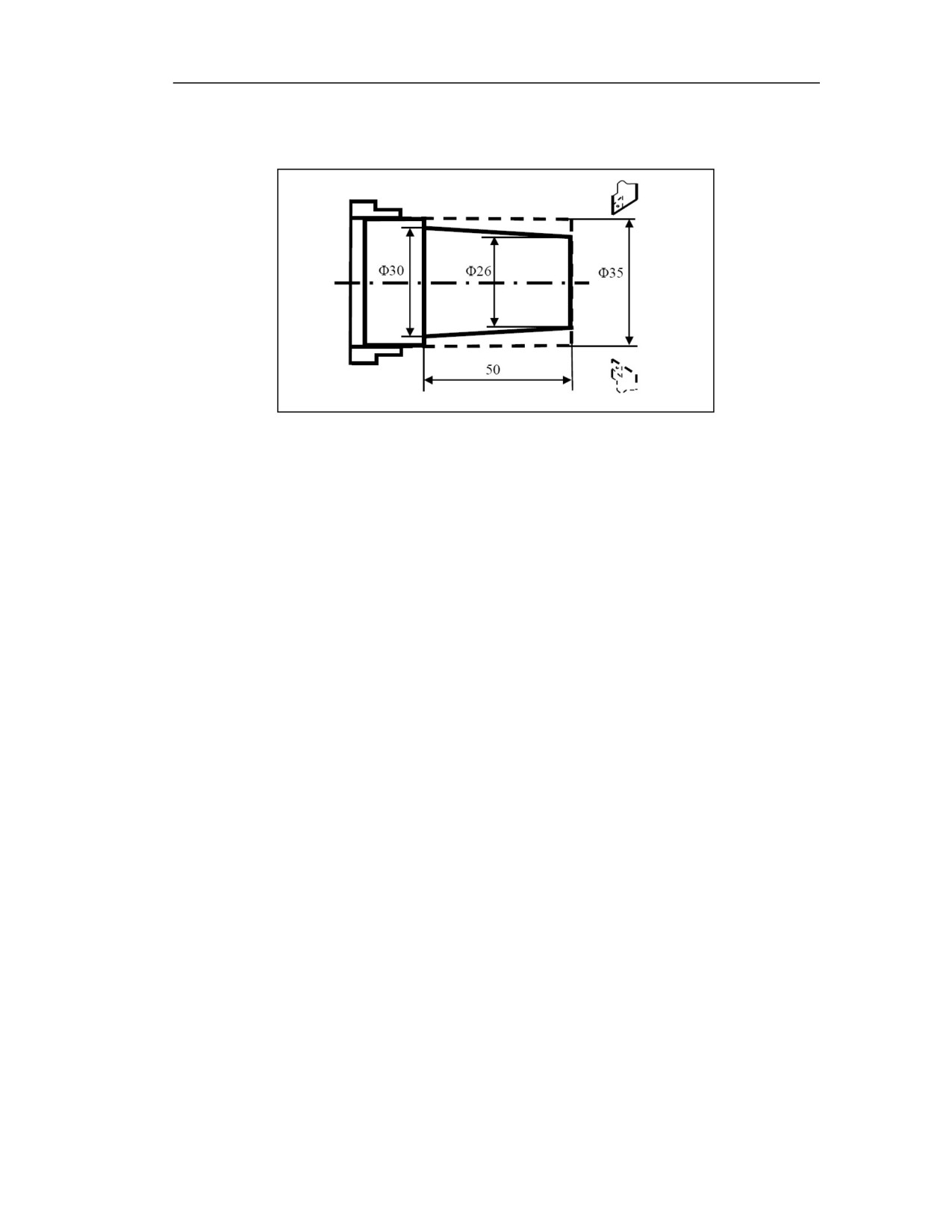
Example 2: Machining the workpiece as shown in the figure below with G80 command to process
simple cone parts by roughing and finishing
%3321
N1 T0101
N2 G00 X100Z40 M03 S460
N3 G00 X40 Z5
N4 G80 X31 Z-50 I-2.2 F100
N5 G00 X100 Z40
N6 T0202
N7 G00 X40 Z5
N8 G80 X30 Z-50 I-2.2 F80
N9 G00 X100 Z40
N10 M05
N11 M30
18
14.1.2 End Face Cutting Cycle (G81)
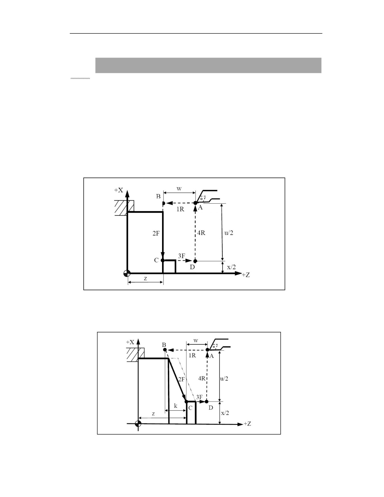
Function and Purpose
With this function, the operation control of 4 linear trajectories can be realized through one block.
The trajectory starts from the starting point A, and returns to the starting point A by
A→B→C→D→A, and finally completes a simple cycle processing, in which the the first and the
forth trajectories are the rapid traverse movements, and the second and the third trajectories are
movements at processing speed. The trajectories are shown in the figure below.
This cycle is suitable for flat face cutting and taper face cutting.
1. Flat face cutting
Cutting path A→B→C→D→A
Cutting start
point
Cycle start
point
Tool retraction
Cutting end point
point
2. Taper face cutting
Cutting path A→B→C→D→A
18
Command Format
1. Flat face cutting
G81 X_/U_ Z_/W_ F_
Parameter
Meaning
X/U Z/W
The coordinates of end point C in workpiece coordinate system in absolute
mode; the directional distance from cutting end pint C to the cycle start
point A in incremental mode, which is represented in U and W, and the
sign is determined by the directions of path 1 and path 2.
F
Feedrate (mm/min)
2. Taper face cutting
G81 X_/U_ Z_/W_ K_ F_
Parameter
Meaning
X/U Z/W
The coordinates of end point C in workpiece coordinate system in absolute
mode; the directional distance from cutting end pint C to the cycle start point
A in incremental mode, which is represented in U and W, and the sign is
determined by the directions of path 1 and path 2.
K
The directional distance along Z from cutting start point B to cutting end
point C.
F
Feedrate (mm/min)
Example
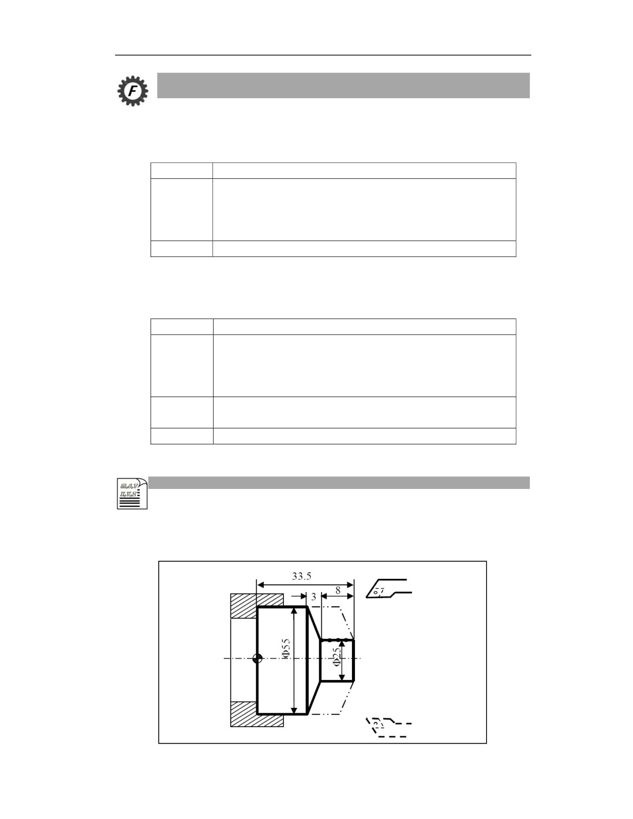
Process the workpiece as shown in the figure below with G81 command, and the dotted line
represents the blank.
18
%3323
N1 T0101 ; Set coordinate system and select No.1 tool
N2 G00 X60 Z45
; Move to the cycle start position
N3 M03 S460
; Spindle rotation CW
N4 G81 X25 Z31.5 K-3.5 F100
; The first cycle, the cutting depth is 2mm
N5 X25 Z29.5 K-3.5
; The cutting depth is 2mm each time
N6 X25 Z27.5 K-3.5
;
The starting point of each cutting is 3mm away from
the outer surface of the workpiece, so the K value is -
3.5
N7 X25 Z25.5 K-3.5
; The forth cycle, the cutting depth is 2mm
N8 M05
; Spindle stops
N9 M30
; Main program end, and reset
Note
(1) If no F value is specified, it will cut at the default speed.
(2) The end face cutting requires special tools for end face cutting
(3) This canned cycle automatically recognizes diameter programming and incremental
programming, no need to switch modes specifically
(4) Before running this program, the spindle must be rotated.
(5) This program can be executed with tool compensation.
14.1.3 Thread Cutting Cycle(G82)
18
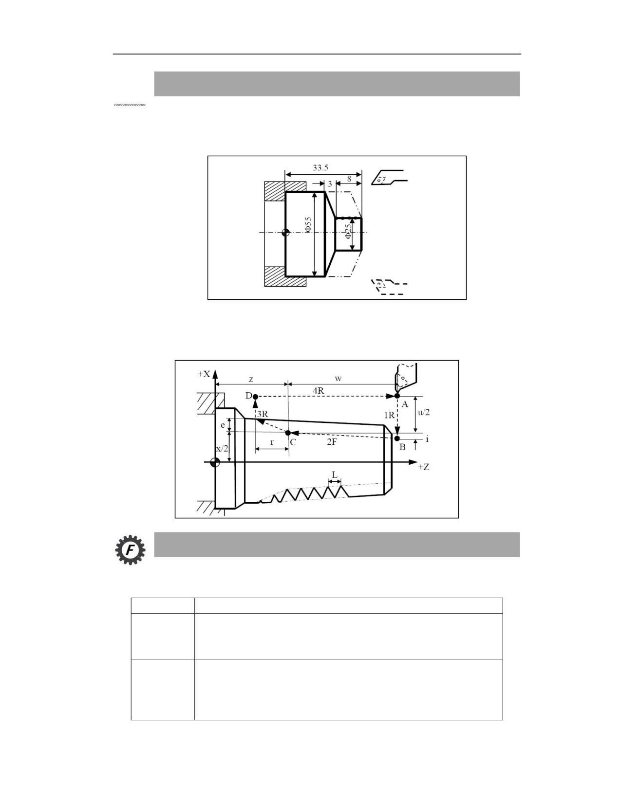
Function and Purpose
1. Straight thread cutting cycle
The cutting path A→B→C→D→A
2. Taper thread cutting cycle
The cutting path A→B→C→D→A
Command Format
G82 X_/U_ Z_/W_ I_ R_ E_ C_ P_ F_
Parameter
Meaning
X/U Z/W
The coordinates of end point C in workpiece coordinate system in absolute
mode; the directional distance from cutting end pint C to the cycle start point
A in incremental mode, which is represented in U and W in the diagram.
I
It is the radius difference between the thread start point B and the thread end
point C. Its sign is the sign of the difference
(no matter it is absolute
programming or incremental programming). This parameter can be omitted for
straight thread.
19
R E
The undercut amount for thread cutting. R and E are both vectors, R is the Z-
direction retraction amount; E is the X-direction retraction amount. R and E
can be omitted, indicating that the retraction function is not required
C
Number of thread starts. When it is 0 or 1, it indicates the single-start thread.
P
For single-start thread cutting, it is the spindle rotation angle of the spindle
reference pulse from the cutting start point (default value is 0); for multi-start
thread cutting, it is the corresponding spindle rotation angle between the
cutting start points of adjacent thread starts.
F
Thread lead; (mm/r)
Example
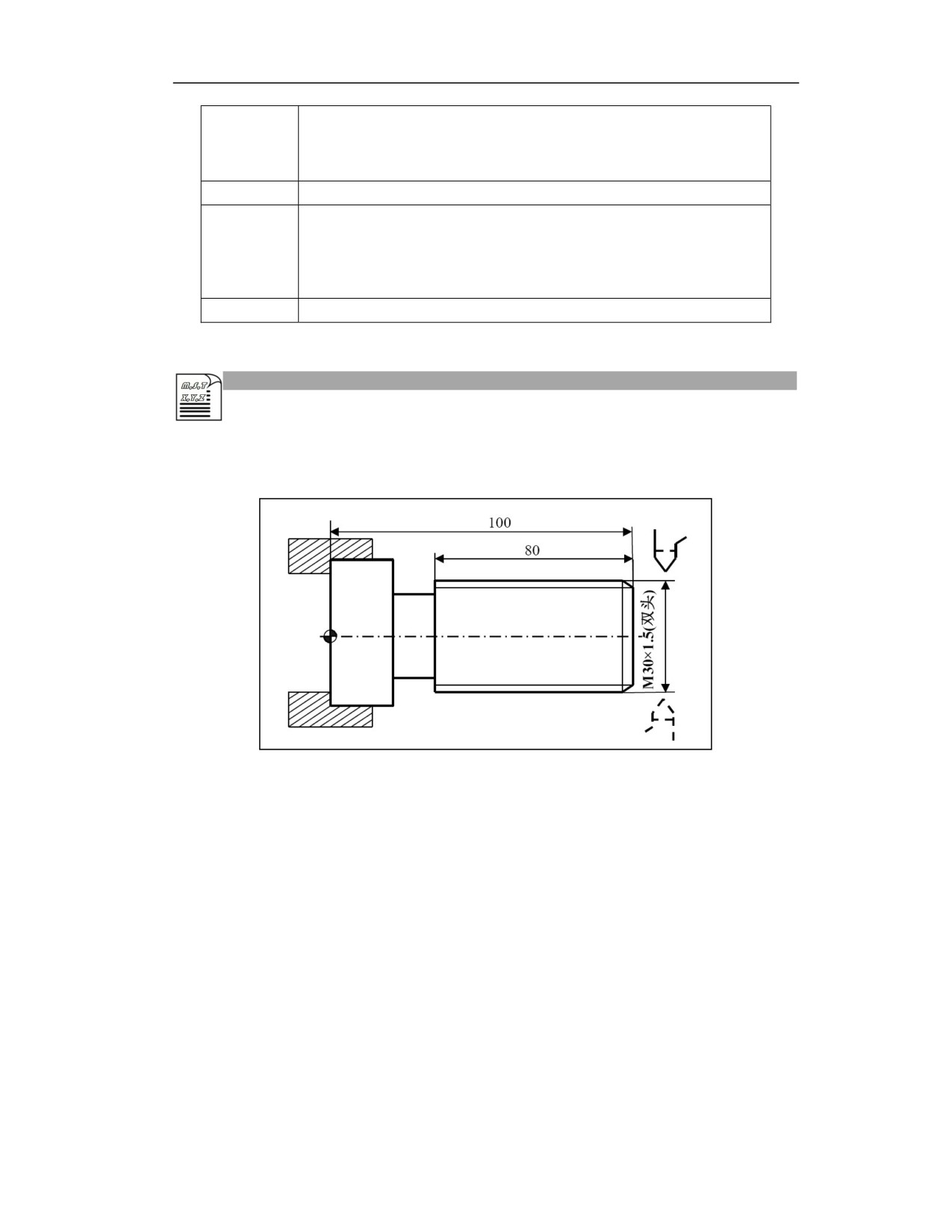
As shown in the figure below, the workpiece is programmed with G82, and the blank shape has
been processed.
%3324
N1 G54 G00 X35 Z104
;
Select coordinate system G54, move to cycle start point
N2 M03 S300
;
Spindle rotates at 300r/min
N3 G82 X29.2 Z18.5 C2 P180 F3
;
The first cycle for thread cutting, the cutting depth is
0.8mm
N4 X28.6 Z18.5 C2 P180 F3
;
The second cycle for thread cutting, the cutting depth is 0.6mm
N5 X28.2 Z18.5 C2 P180 F3
;
The third cycle for thread cutting, the cutting depth is 0.4mm
N6 X28.04 Z18.5 C2 P180 F3
; The forth cycle for thread cutting, the cutting depth is 0.16mm
N7 M30
; Spindle stops, main program end, and reset
19
Note
(1) If the retraction function is required, please note that the signs of the R and E values must be
coordinated with the thread cutting direction. Retraction in the opposite direction of thread
processing may damage the thread. At the same time, only R can be specified without specifying
E, but if E is specified, R must be specified. When R and E are zero, the undercut amount is forced
to F×0.68;
(2) The thread cutting cycle is the same as the G32 thread cutting. In the feed hold state, the cycle
will stop after completing all actions;
(3) The override cannot be changed at the time of thread cutting;
(4) F value can be inherited, if there is no value to inherit, it will alarm;
(5) The 90-degree undercut is #54019 in the user-defined macro variable.
14.1.4 End Face Deep-hole Drilling Cycle(G74)
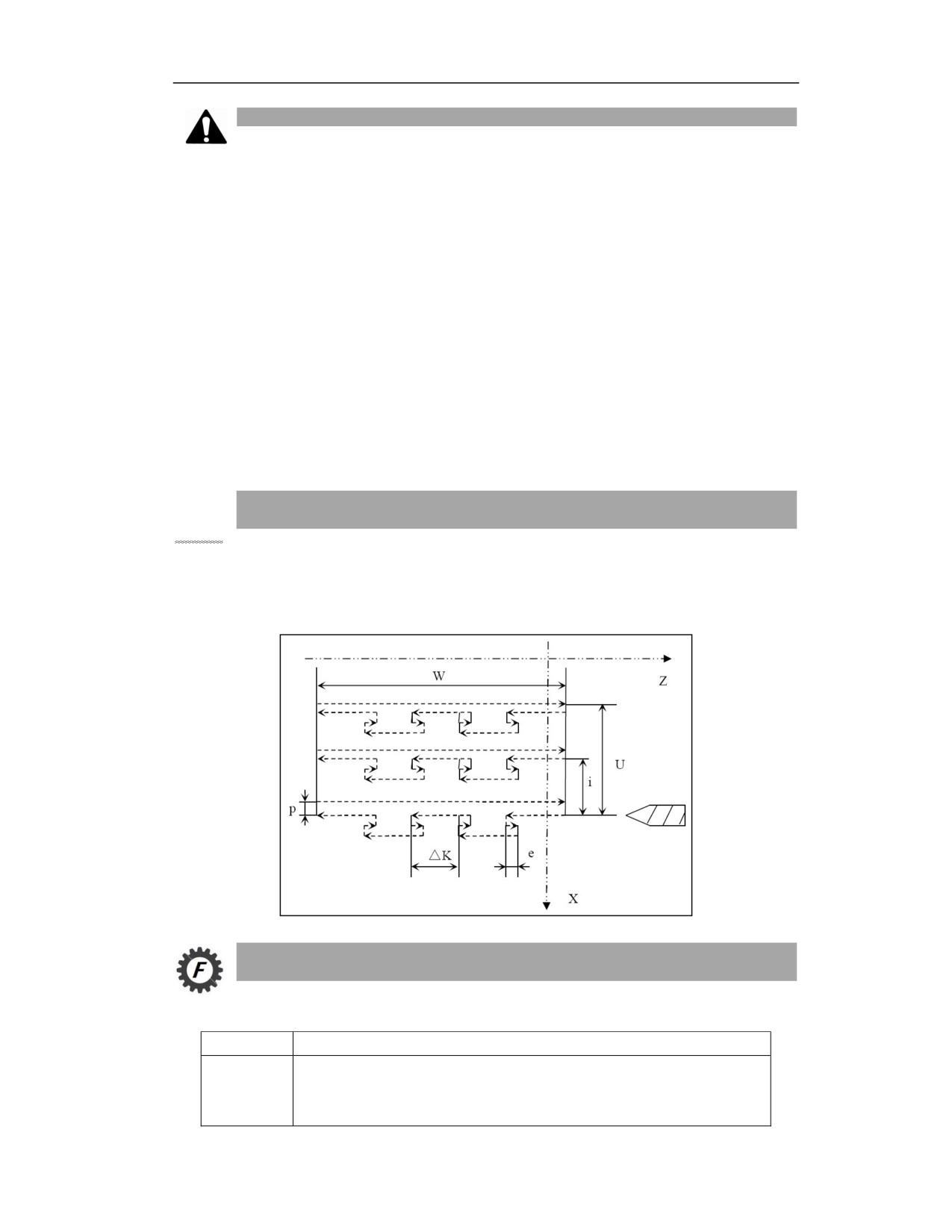
Function and Purpose
This cycle can perform deep hole drilling on the end face. As shown in the figure below.
The tool path A→B→C→D→A
Command Format
G74 X_/U_Z_/W_ Q(△K)_R(e)_ I(i)_P(p)_
Parameter
Meaning
X/U
The coordinates of end point of hole bottom on X in workpiece coordinate
system in absolute programming; in incremental programming, the directional
distance from end point of hole bottom to the cycle start point, which is
19
represented by U in the graph. This value can be left blank.
Z/W
The coordinates of end point of hole bottom on Z in workpiece coordinate
system in absolute programming; in incremental programming, the directional
distance from end point of hole bottom to the cycle start point, which is
represented by W in the graph.
R
Undercut amount on Z, can only be positive, and can be left blank.
Q
Feed depth, can only be positive.
I
The width of each cut when drilling a wide hole, can only be positive, and can
be left blank.
P
Retract amount on X. When I is specified, P can only be positive; when I is not
specified, P can be both positive and negative, and can be left blank.
Description
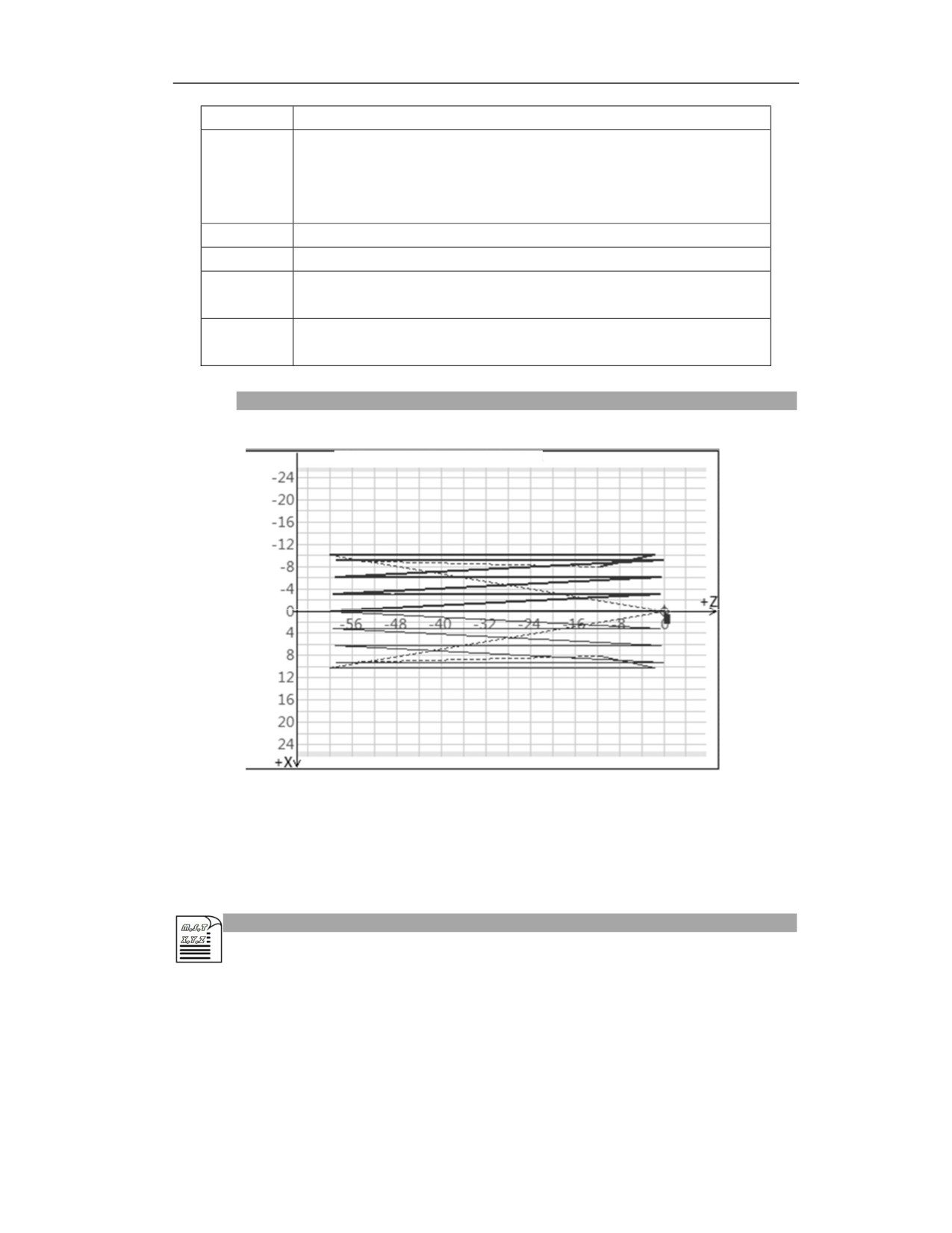
Blank length: 406.1, radius 120.0, scaling 1.748
As shown in the figure above, it is the drilling trajectory of G74. Each time after drilling into the
bottom of the hole, it moves Q distance in the X direction and then drills again until the remaining
width in the X direction is less than Q, then completes the X axis movement, and drills finally so
as to achieve the drilling of a fixed width hole.
Example
19
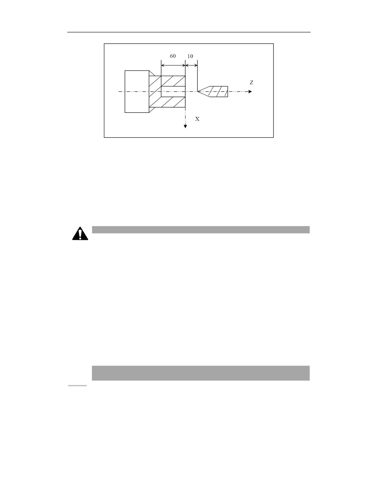
%1234
T0101
M03S500
G01 X0 Z10F200
G74 X-10Z-60R1Q5I3P1
M30
Note
(1) Modal inheritance is not supported. If the following lines of G74 are XZ coordinates, the
program will not continue drilling, but o run the coordinates with G01.
(2) If need to drill continuously, user needs to write multiple lines of G74 continuously, and
commands such as RQIP will not be inherited.
(3) Clockwise drilling and counterclockwise drilling are supported.
(4) Pay attention to selecting appropriate speed values (including dry run). Even for the virtual
pattern in the dry run, the system will display the actual tool path when the speed is too fast. When
the speed is adjusted to a high level in dry run, the drilling pattern will be distorted.
(5) Pay attention to the width of the tool at the time of wide groove cutting.
14.1.5 Outer Diameter Grooving Cycle (G75)
Function and Purpose
This cycle is used for grooving the outer diameter of the workpiece.
19
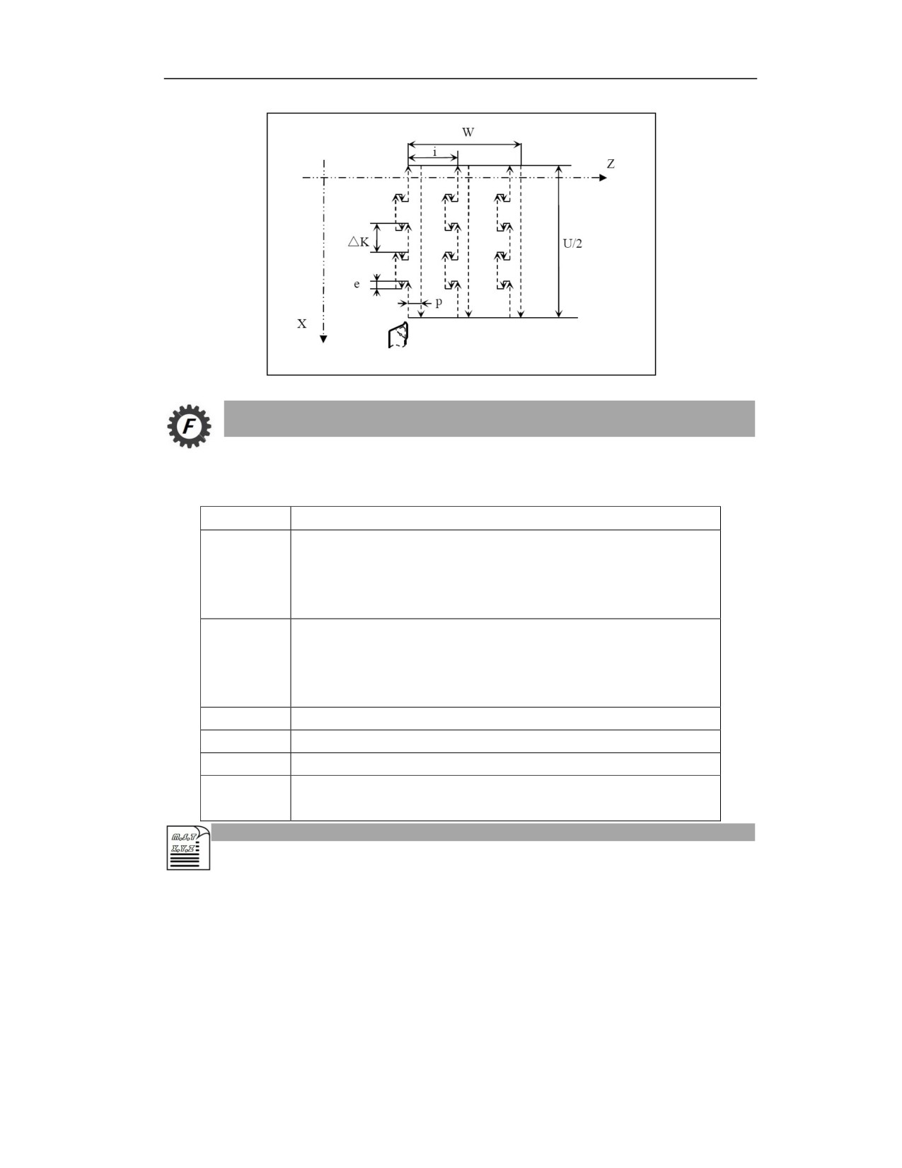
Command Format
G75X_/U_Z_/W_ Q(△K)_R(e)_ I(i)_P(p)_
Parameter
Meaning
X/U
The coordinates of end point of hole bottom on X in workpiece coordinate
system in absolute programming; in incremental programming, the
directional distance from end point of hole bottom to the cycle start point,
which is represented by U in the graph.
Z/W
The coordinates of end point of hole bottom on Z in workpiece coordinate
system in absolute programming; in incremental programming, the
directional distance from end point of hole bottom to the cycle start point,
which is represented by W in the graph.
R
Retract amount on X, can only be positive, and can be left blank.
Q
Feed depth, can only be positive.
I
Groove width, can only be positive, and can be left blank.
P
Undercut amount on Z. When I is specified, P can only be positive; when I
is not specified, P can be both positive and negative, and can be left blank.
Example
Example 1: G75 outer diameter grooving cycle programming example.
19
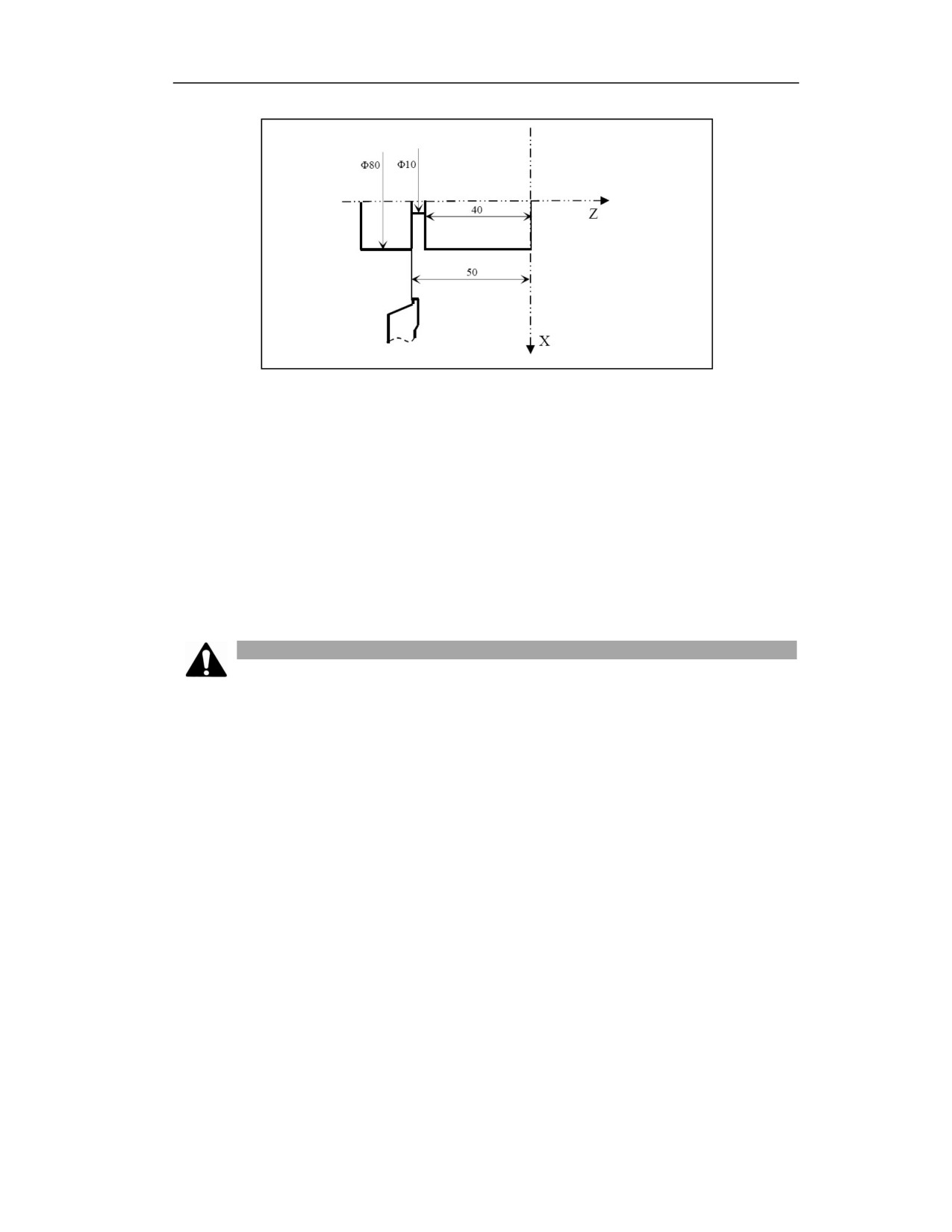
%1234
T0101
M03S500
G01 X50 Z-50F200
G75 X10Z-40R1Q5I3P2
M30
Note
(1) If K is not defined, user macro #54005 needs to be set as the tool retraction amount.
(2) If Q is not defined, the Q in the previous line will be inherited. If Q is not defined in the first
line, then Q will be 0.
(3) If R is not defined, then R is 0 by default.
(4) Modal inheritance is not supported. If the following lines of G75 are XZ coordinates, the
program will not continue drilling, but to run the coordinates with G01.
(5) If need to drill continuously, user needs to write multiple lines of G75 continuously, and
commands such as RQIP will not be inherited.
19
14.2
Drilling Canned Cycle for Lathe System
There are four drilling cycles for lathes system:
G command
Function
G83
Axial drilling cycle
G87
Radial drilling cycle
G84
Axial rigid tapping cycle
G88
Radial rigid tapping cycle
With this cycle, a block containing G code is used to complete the machining operations with
multiple block commands, so that the program can be simplified.
Note
(1) Cycles described in this chapter only can be used for lathe system.
(2) Commands G83, G87, G84, and G88 do not have positioning function. It is necessary to use
G01 and G00 outside the canned cycle for positioning.
14.2.1 Axial Drilling Cycle(G83)/Radial Drilling Cycle(G87)
Function and Purpose
Turning centers with powered tool often require axial or radial hole processing. The G83
command of this system can be used to drill axial holes; G87 can be used to drill radial holes. For
the two processing methods, there only is the difference in the feed axis, and the drilling trajectory
is exactly the same. The axial drilling is fed along Z axis and the radial drilling is fed along X
axis.
In addition, axial drilling is also suitable for conventional lathes. At this time, the workpiece or
drill can be installed on the lathe spindle to form the main cutting movement, and the drill or
workpiece can be installed on the tool holder to perform the Z-axis feed movement, thereby
realizing the axial drilling.
Command Format
1. Axial drilling cycle
G83Z(W)_R_Q_K_P_F_H_
2. Radial drilling cycle
G87X(U)_R_Q_K_P_F_H_
Parameter
Meaning
19
X/Z
Coordinates of hole bottom
R
Distance from initial level to R level
Q
Cutting depth
P
Dwell time at the hole bottom
F
Feedrate
K
Retraction distance
H1
High speed deep hole drilling. Retraction of the specified
distance K
H2
Deep hole drilling. Retraction to R point
H3
Spot drilling. Drill directly to the hole bottom
Description
According to the different technological requirements of drilling process, this function sets three
kinds of drilling cycle trajectories, namely conventional hole drilling, high speed deep hole
drilling, and deep hole drilling. The three modes are set by H1, H2, H3 respectively.
H1 is set as high-speed deep hole drilling, chip breaking needs to be taken into consideration, and
the chip removal effect is not very good;
H2 is set as deep hole drilling, chip breaking and chip removal need to be taken into consideration;
H3 is set as conventional hole drilling, which is mainly suitable for shallow hole processing,
without considering chip removal and chip breaking.
High-speed deep hole drilling --- H1 mode
19
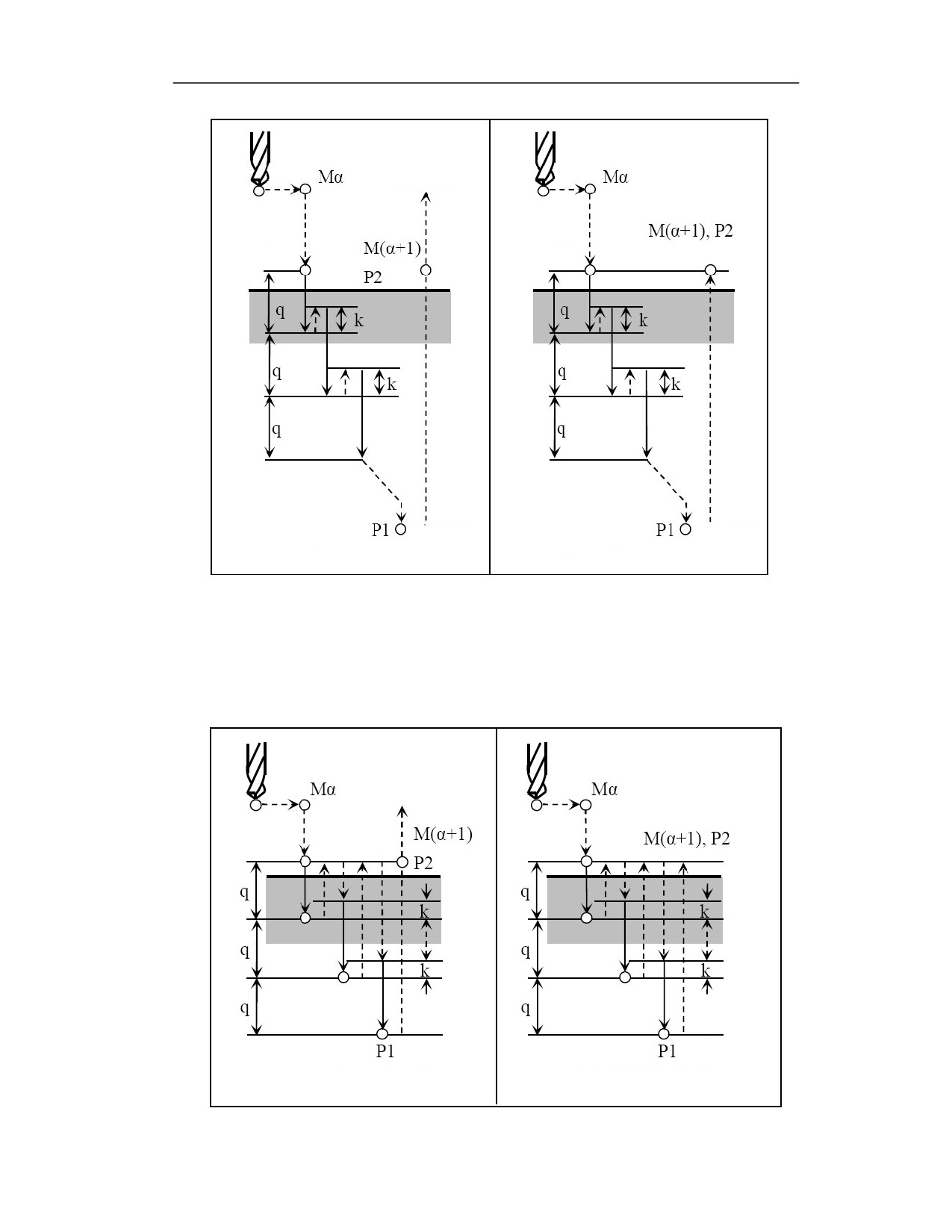
Initial level
Point R
Point R
Point R
Point Z/X
Point Z/X
G83 or G87 (G98)
G83 or G87 (G99)
Deep hole processing can be realized through repeated advance and retreat;
The retraction amount K is small after drilling each time. Chip breaking can be
achieve, and chip removal effect is not very good.
Deep hole drilling - H2 mode
Initial level
Point R
Initial level
Point Z./X
Point Z./X
G83 or G87 (G98)
G83 or G87 (G99)
19