HNC8 Series CNC Controller. Programming Manual (V2.4) - page 4
G13
G0Z10
G109
G0X120
M105
M30
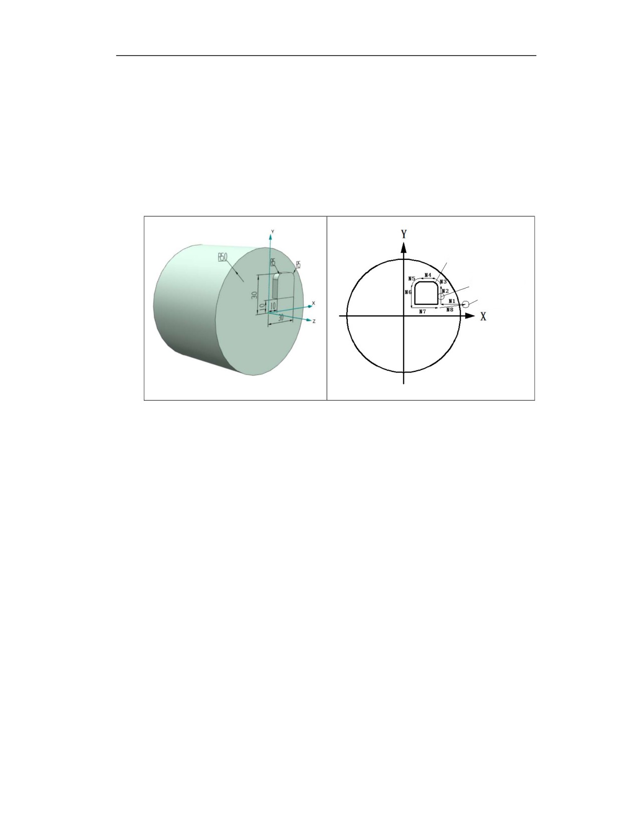
Example 2: Face contour milling
Programmed
contour
Programmed
path
Tool
%1234
G54
T0101;The workpiece coordinate system is built at the center of rotation on the right end
of the blank, with end milling cutter φ6
G108;Spindle is switched from speed mode to position mode
M103 S1=2000;Tool rotation CW
G37; Radius programming
G0X52Z50C0
G0 Z-5
G12X0CO
G1X50C10F500
N1 G42D1G01X30C10(D1=3)
N2 G1C25
N3 G03X25C30R5
N4 G1X15
N5 G03X10C25R5
N6C10
N7 X30
N8 G40X50
G13
G0Z10
G109;Spindle is switched from speed mode to position mode
12
G0X52
M105;Tool stops
M30
Note
Before entering the polar coordinate interpolation mode, cancel the tool radius compensation and
tool length compensation, and specify the tool compensation in the polar coordinate interpolation
mode.
11.10
Cylindrical interpolation(G07.1)
Function and Purpose
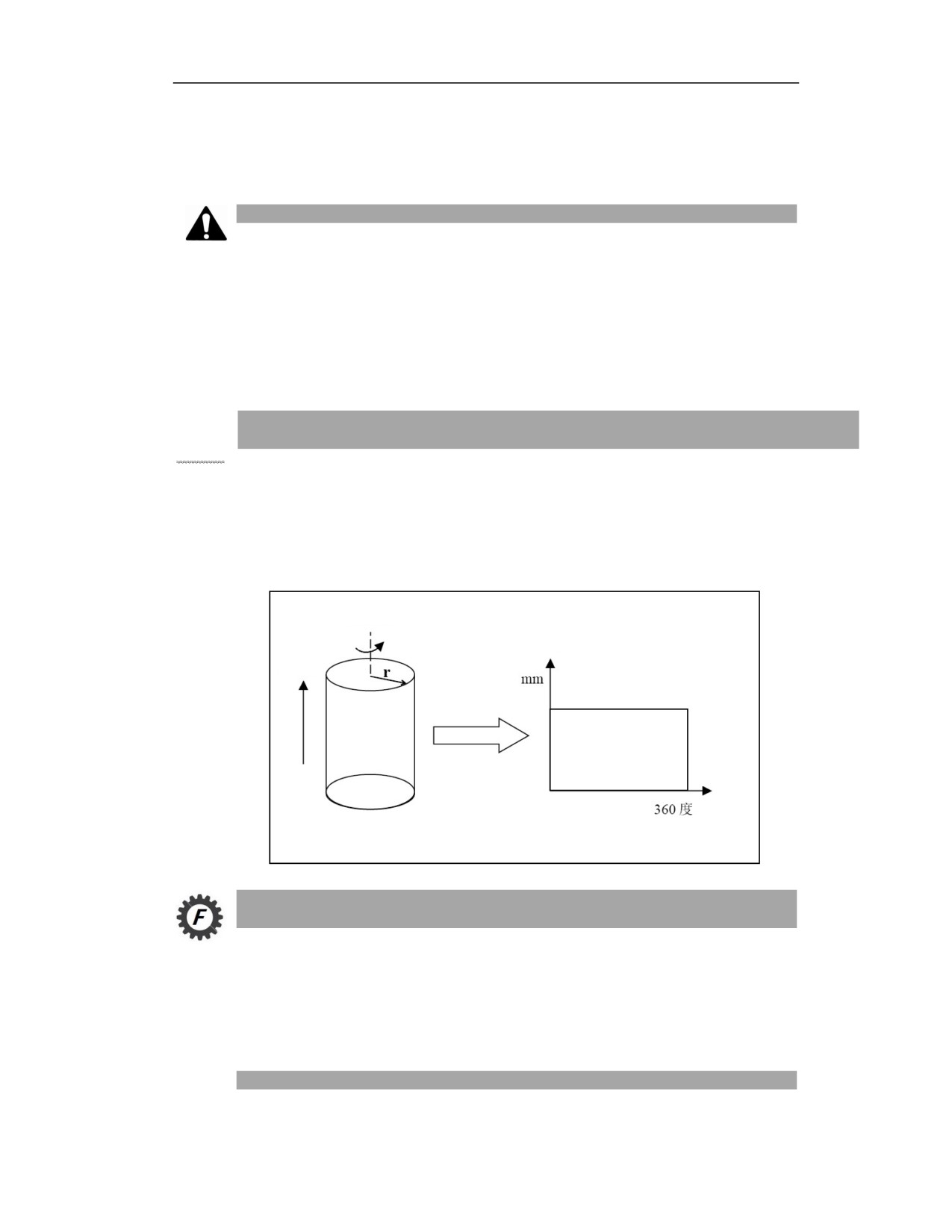
With this function, the shape of the side surface of the cylinder (the shape on the cylindrical coordinate
system) is expanded into a plane, and the expanded shape is used as the plane coordinate for the program
command, then the system converts it to the movement on linear axis and rotary axis of the cylindrical
coordinate when performing machining to execute the contour control.
Rotary axis
Linear axis
Linear
axis
Expand the cylinder
Rotary
axis
Command Format
G07.1 RC= r
; Start of cylindrical interpolation (r: radius of cylinder)
……
G07.1 RC=0
; End of cylindrical interpolation
Description
12
Circular interpolation
The circular interpolation (G02, G03) in the cylindrical interpolation plane is performed, and the
coordinate system plane is determined based on the parallel axis in the cylindrical interpolation.
Set X axis as the horizontal axis in
G02, G03 are specified in X-C plane
Parm040092 = 0
the cylindrical interpolation plane
(G17) with IJR programming
Set Y axis as the horizontal axis in
G02, G03 are specified in Y-C plane
Parm040092 = 1
the cylindrical interpolation plane
(G19) with JKR programming
Set Z axis as the horizontal axis in
G02, G03 are specified in Z-C plane
Parm040092= 2
the cylindrical interpolation plane
(G18) with IKR programming
Compensation
The tool radius compensation and tool length compensation should be cancelled before entering
the cylindrical interpolation mode, and the tool compensation should be specified in the
cylindrical interpolation mode.
Related parameters
Parameter name
Parameter
Default
Description
Channel parameter
Parm040090
5(C axis)
Rotary axis No. in cylindrical interpolation
(CH0)
Parm040091
2(Z axis)
Linear axis No. in cylindrical interpolation
Parm040092
1(Y axis)
Parallel axis No. in cylindrical interpolation
Example
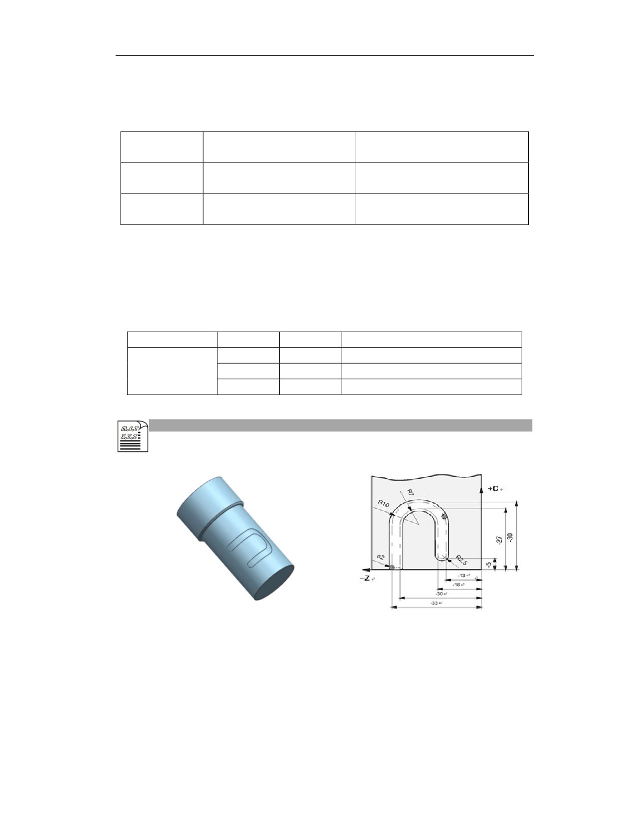
Example 1: Contour milling
G54
T0101;Radial face milling cutter ø2, workpiece ø30
G108
G19;Select a plane
M103 S1=1000;The second spindle rotates CW, the direction of tool rotation is related
to the tool post
G0X50C0
12
G0 Z-31.5
G07.1RC=15
G95 G1 X29 F0.08
G42D1 G1 C1.5 Z-33
G1C20
G2C20Z-13R10
G1 C6.5
G2 C6.5Z-16R1.5
G1 C20
G3 C20Z-30R7
G1 C0 Z-33
G40 C1.5 Z-31.5
G0 X32
G0 Z10
G07.1 RC=0;
G109G18
G0X150Z150
M105
M30
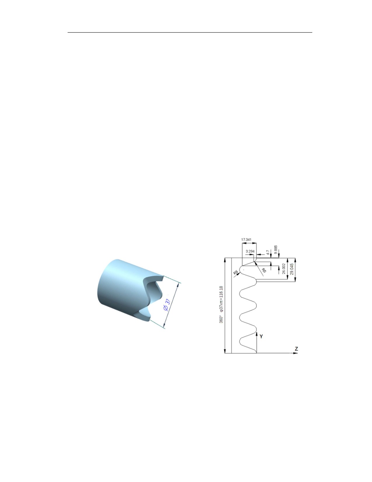
Example 2: Contour milling
%1234
%1
G54
G91
T0101; Radial face milling cutter ø4,
G42 D1G1Z-5C0F100
workpiece ø37
G3 C-14.564Z-3.294 R5
G108
G1 C-16.006Z-14.047
G94
G2 C-29.128 R5
G19; Select a plane
G1 C-16.006 Z14.047
M103 S1=1000
G3 C-14.564 Z3.294 R5
12
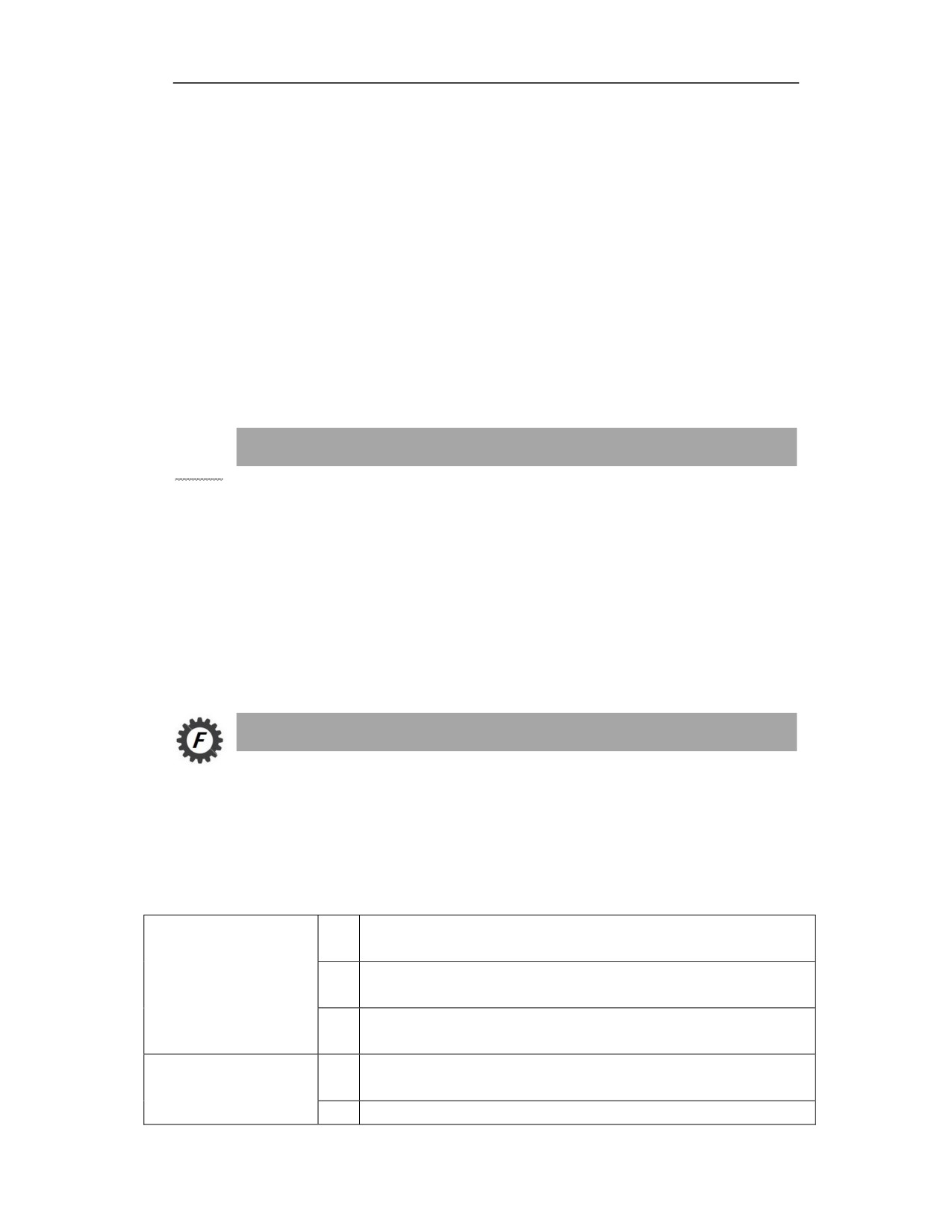
G0X50C0
G40G1 Z5
G0 Z50
M99
G07.1 RC=18.5
G0Z5
M98P1L4
G90
G07.1 RC=0;
G109
G18
G0X100 Z100
M105
M30
11.11
Polar Coordinate Command(G15/G16)
Function and Purpose
When the angle and radius are marked on the drawings of the parts, the "polar diameter" and
"polar angle" of polar coordinate are used to define the end positions of the program, which can
greatly simplify the programming calculation.
In the specified plane of the polar coordinate system, the counterclockwise direction of the polar
axis movement is the positive direction of the polar angle, and the clockwise direction of the polar
axis movement is the negative direction of the polar angle.
Both "polar diameter" and "polar angle" can be specified under absolute
programming/incremental programming (G90, G91).
Command Format
G17(or G18/G19);
G16 ;
G90 X- Y-
(or G91 X- Y-);
G15;
XY plane: polar radius is specified with X axis, and polar angle is
G17
specified with Y axis.
To specify the plane of
ZX plane: polar radius is specified with Z axis, and polar angle is specified
G18
polar coordinate system
with X axis.
YZ plane: polar radius is specified with Y axis, and polar angle is specified
G19
with Z axis.
To specify the origin of
Workpiece coordinate system zero (or local coordinate system zero) is
G90
polar coordinate system
specified as the origin of polar coordinate system (polar origin)
G91
The current position is specified as the origin of polar coordinate system
12
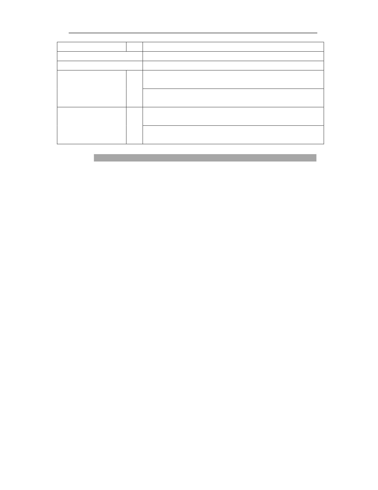
(polar origin)
G16
Polar coordinate programming starts
G15
Polar coordinate programming ends
In absolute programming: Polar diameter measured from the workpiece
To specify polar diameter
X
coordinate system zero (or local coordinate system zero)
In incremental programming: Polar diameter measured from the current
point
In absolute programming: Polar angle measured with workpiece zero as
To specify polar angle
Y
the polar origin
In incremental programming: Polar angle measured with the current point
as the polar origin
Description
Polar coordinate system origin setting
There are two ways to set the polar coordinate system origin:
(1) At the time of programming with polar coordinate, if the polar origin is defined in absolute
mode (G90), the polar coordinate system origin will be the workpiece origin or the local
coordinate system origin.
(2) At the time of programming with polar coordinate, if the polar origin is defined in incremental
mode (G91), the polar coordinate system origin will be the current point.
Polar coordinate command position
(1) When workpiece coordinate system origin is the center of polar coordinate,
The workpiece coordinate system origin is the polar coordinate center when the radius is specified
in absolute mode.
Only when the local coordinate system (G52) is used, the origin of the local coordinate system is
the center of the polar coordinate.
12
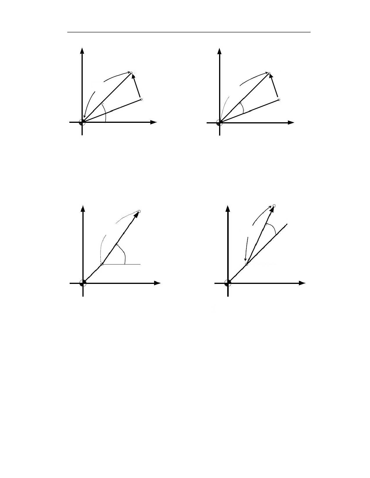
Command position
Command position
Radius
Radius
Current position
Current position
Angle
Angle
When the angle is in absolute mode
When the angle is in incremental mode
(2) When the current position is the center of polar coordinate,
The current position is the polar coordinate center when the radius is specified in incremental
mode.
Command position
Command position
Angle
Radius
Radius
Angle
Current position
Current position
When the angle is in absolute mode
When the angle is in incremental mode
(3) When radius command is ignored,
When the radius is ignored, the origin of the workpiece coordinate system is the polar coordinate
center, and the distance from the polar coordinate center to the current position is the radius. Only
when the local coordinate system (G52) is used, the local coordinate origin is the polar coordinate
center.
12
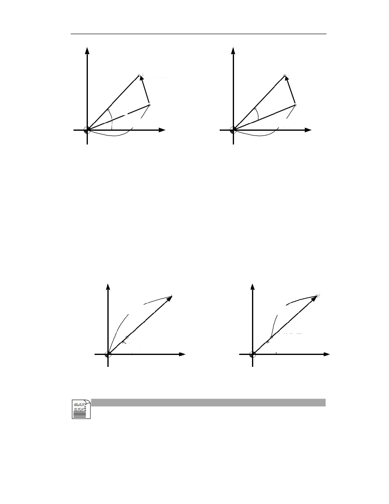
Command position
Command position
Current position
Angle
Current position
Angle
Radius
Radius
When the angle is in absolute mode
When the angle is in incremental mode
(4) When angle command is ignored,
When the angle command is ignored, the angle of the current position in the workpiece coordinate
system is the angle command.
When the radius is commanded in the absolute mode, the origin of the workpiece coordinate
system is the polar coordinate center. Only when the local coordinate system (G52) is used, the
origin of the local coordinate system is the polar coordinate center.
In addition, when the radius is specified in the incremental mode, the current position is the polar
coordinate center.
Command position
Command position
Radius
Radius
Current position
Current position
Angle
Angle
When the angle is in absolute mode
When the angle is in absolute mode
Example
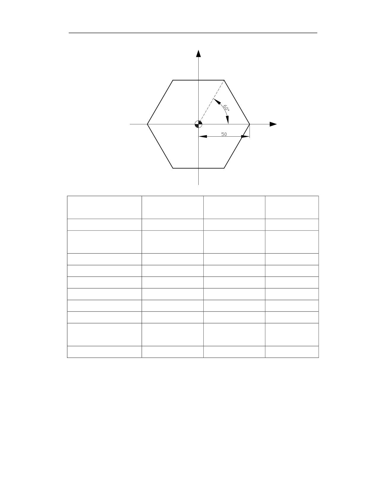
Example 1: Mill a hexagon with the polar coordinate programming, the workpiece origin is set at
the center of the hexagon (as shown below), and the processing path is a→b→c→d→e→f.
12
Y
c
b
d
O
a
X
e
f
Processing path
Absolute
Incremental
Commanded
programming
programming
position
Position to a point
G54G0X50Y0
G54G0X50Y0
(X50、Y0)
Polar coordinate command
G17G90G16
G17G90G16
(X50、Y0)
starts
a→b
G1X50Y60F120
G1X50Y60F600
(X25、Y43.3)
b→c
Y120
G91Y60
(X-25、Y43.3)
c→d
Y180
Y60
(X-50、Y0)
d→e
Y240
Y60
(X-25、Y-43.3)
e→f
Y300
Y60
(X25、Y-43.3)
f→a
Y360
Y60
(X50、Y0)
Polar coordinate command is
G15
G15
(X50、Y0)
disabled
Program ends
M30
M30
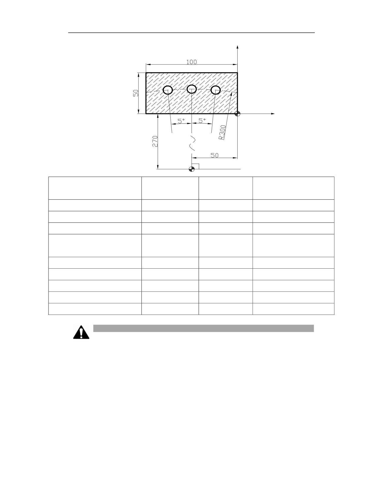
Example 2: As shown in the figure below, use polar coordinate programming to drill 3 holes with
a diameter of 10mm on the workpiece.
(The workpiece coordinate system zero is O, and the rotation polar origin A of polar coordinate
is outside the worktable the machine tool)
12
Y
a
b
c
O
X
A
Absolute
Incremental
Processing path
Commanded position (X, Y, Z)
programming
programming
Position above the zero
G54G0X50Y0Z30
G54G0X50Y0Z30
(50、0、30)
Establish G52 local coordinate system
G52X-50Y-270
G52X-50Y-270
(50、270、Z30)
Polar coordinate command starts
G17G90G16
G17G90G16
(50、270、Z30)
Drill hole at c point in the plane
G82X300Y85Z-
G82X300Y85Z-
(26.147,298.858,-10)
10R5F100
10R5F100
Drill hole at b point in the plane
Y90
G91Y5
(0、300、-10)
Drill hole at a point in the plane
Y95
Y5
(-26.147,298.858,-10)
Polar coordinate command is disabled
G15
G15
(-26.147,298.858,30)
Local coordinate system is cancelled
G52X0Y0
G52X0Y0
(-76.147,28.858、30)
Program ends
M30
M30
Note
(1) The axis commands accompanied by the following commands will not be regarded as polar
coordinate commands;
Dwell G04
Programmable data input G10
Local coordinate system G52
Workpiece coordinate system change G92
Machine coordinate system selection G53
Coordinate rotation G68
12
Scaling G51
(2) In polar coordinate mode, the angle and radius R cannot be specified;
(3) For polar coordinate programming, when radius is specified in absolute mode, the workpiece
origin is set as the polar coordinate center; when radius is specified in incremental mode, the
current position is set as the polar coordinate center. However, when only the angle is specified
in the command, regardless of whether it is in absolute or incremental mode, the workpiece origin
is set as the polar coordinate center.
11.12
NURBS Spline Interpolation
Function and Purpose
This function only needs to specify the NURBS
(non-uniform rational B-spline) curve
(degree/weight/node/control point) used in curve/curved surface processing to realize NURBS
curve processing without replacing tiny line segments.
In NUBRS interpolation, interpolation is performed at the commanded speed, but at positions
with large curvature, the speed is limited to a speed that does not exceed the allowable acceleration
of the machine tool.
Command Format
NURBS P_ K_ X_ Y_ Z_ W_ F_ E_ ;
Parameter
Meaning
P
Order of NURBS curve, only cubic spline is supported. P is 4
K
Node
X, Y, Z
Coordinate value of control point
W
Weighting
F
Feedrate
E
2nd feedrate
Description
Cancel interpolation
NURBS belongs to the 01 group of modal, and the NURBS interpolation modal can be released
by specifying G01 or G00.
Order of curve
13
P is to specify the order of NURBS curve;
When P=4, it indicates the cubic NURBS curve;
P is a modal address word, and P will remain valid until it is changed or other modal commands
of group 01 are specified.
Node
In NURBS interpolation, user must specify the first control point as the starting point and the final
control point as the end point.
In addition, when specifying the node of the first block, please use the following format:
Single spline
NURBS P4 K{0,0,0,0,1} X1 Y0 Z0
Double-spline
NURBSB P4 K{0,0,0,0,0.5}Q{10,0,0,38.28,0,28.28} W1F60
Weighting
The weight is the weight of the designated control point in the same block. When it is omitted,
the default value is 1.0
Compensation
Tool radius compensation cannot be used in NURBS curve interpolation.
Description
Single spline NURBS is generally used for three-axis small line segment interpolation.
Double-spline NURBS is generally used for five-axis small line segment interpolation.
Example
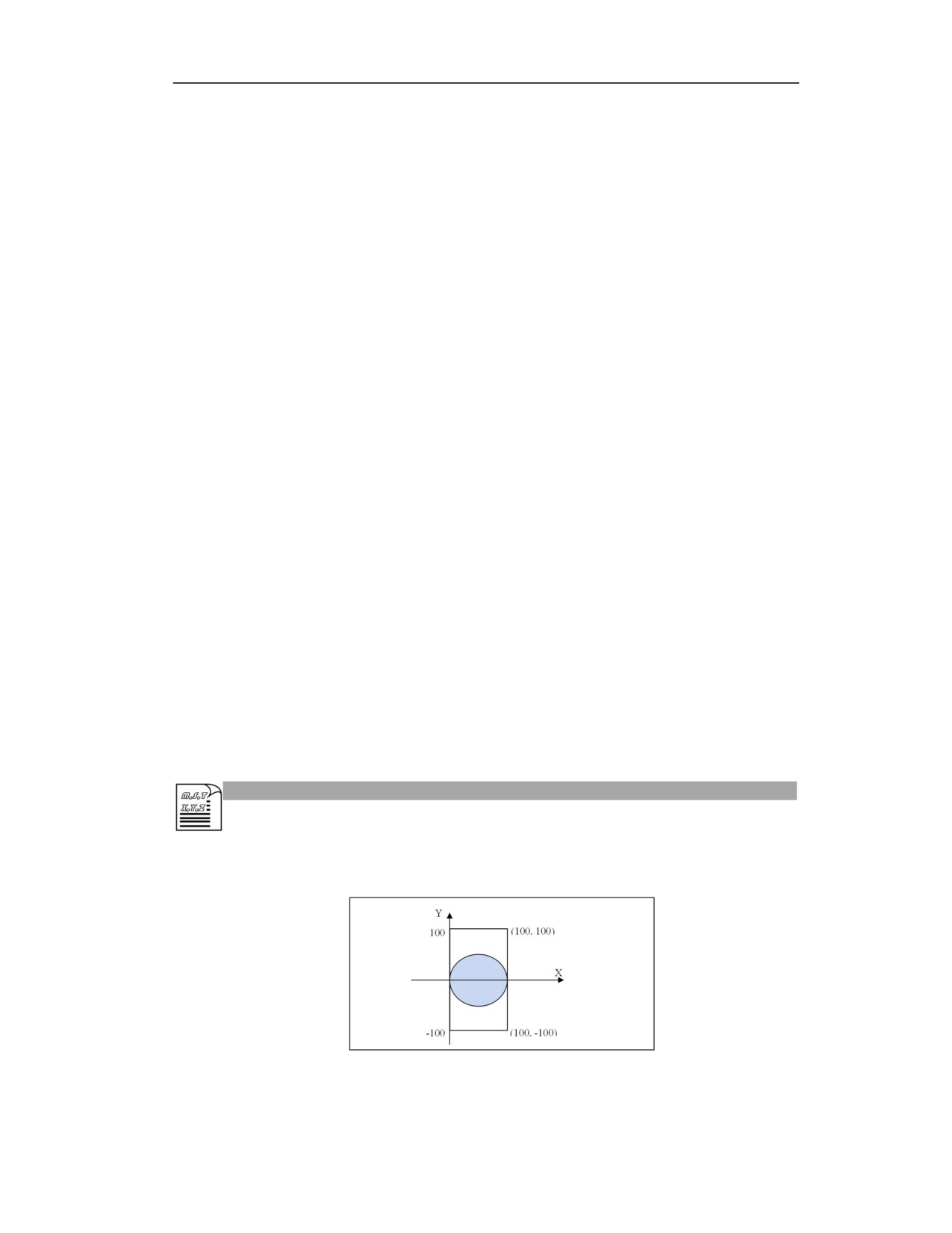
R=50mm Please use the single spline NURBS interpolation for the full circle shown as below,
R=50mm.
%0001
G54
13
G90G17F500G64
G01X0Y0Z0
NURBS P4 K{0.0,0.0,0.0,0.0,0.5} X0.0Y0.0Z0.0 W1.0
K0.5
X0.0000 Y100.0 W0.3333
K0.5
X100.0 Y100.0 W0.3333
K1.0
X100.0 Y0.0
W1.0
K1.0
X100 Y-100.0 W0.3333
K1.0
X0.0
Y-100 W0.3333
K1.0
X0.0
Y0.0
W1.0
M30
11.13
HSPLINE Spline Interpolation
Function and Purpose
HSPLINE is the abbreviation of Hermite SPLINE. Hermite interpolation function can also
improve the processing effect of small line segments and make the processed surface smooth.
Unlike the NURBS curve, the Hermite curve passes through the control points, while the Nurbs
curve does not pass through the control points. The system performs spline interpolation by
specifying the control points and vectors of the Hermite curve
Command Format
HSPLINE P_X_Y_Z_I_J_K_W_F_ ;
Parameter
Meaning
P
Degree of HSPLINE spline curve
X,Y,Z
Coordinates of control point
I,J,K
Vector of control point
W
Weighting
F
Order of Hermite curve
Description
Cancel interpolation
HSPLINE belongs to the 01 group modal, and the HSPLINE interpolation modal can be cancelled
by specifying G01 or G00.
13
Degree of curve
The degree of HSPLINE spline curve is specified with P, and this value is 3 currently.
Compensation
The tool radius compensation cannot be used in the HSPLINE curve interpolation mode.
Example
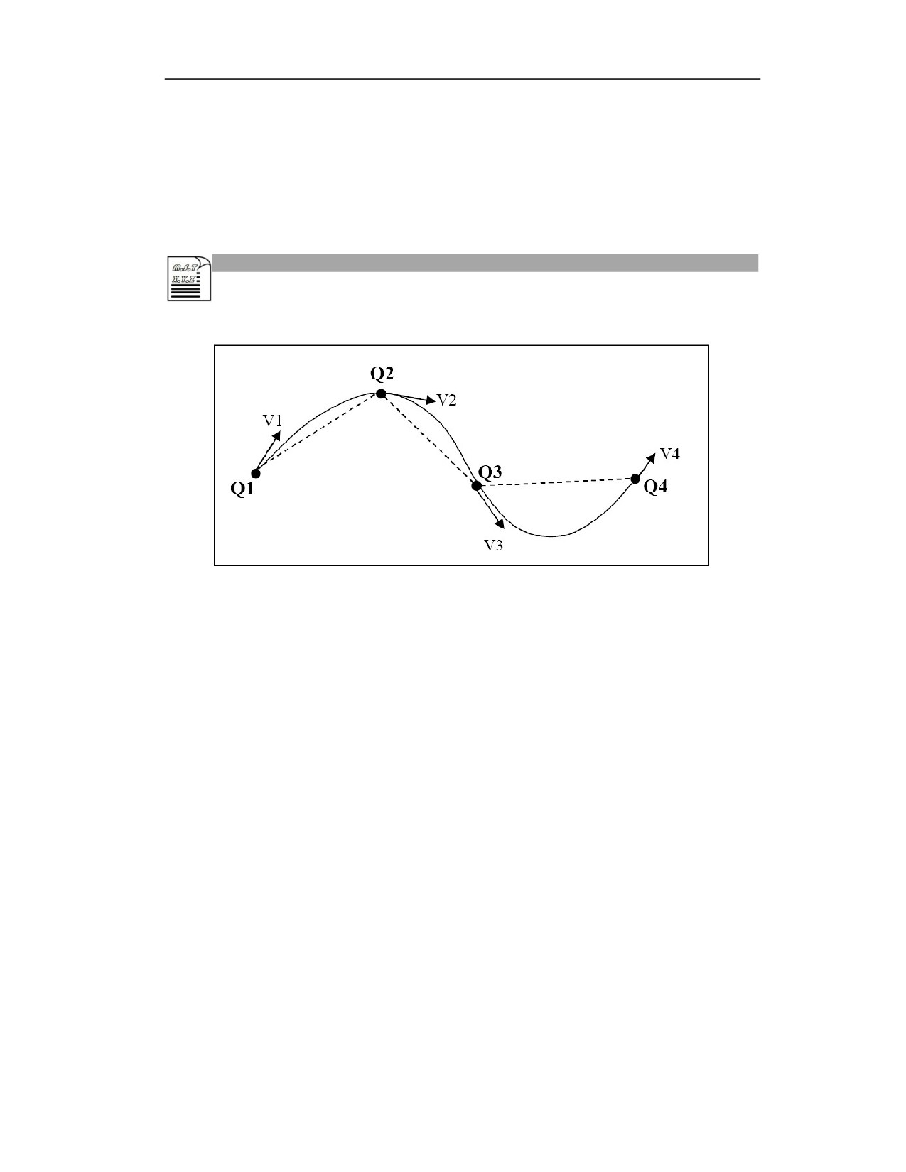
Example 1: Use cubic Hermite spline to interpolate the following spatial curve
%0001
G54G0X0Y0Z0
G90G17 F1000G64
X0.005Y-0.987Z0.04
HSPLINE P3 X0.005 Y-0.987 Z0.040 I1.000 J-0.026 K-0.002;Q1
X0.748 Y-0.727 Z0.027 I0.756 J0.655 K-0.016
;Q2
X1.049 Y-1.097 Z0.023 I0.967 J0.256 K-0.011
;Q3
X1.249 Y-0.727 Z0.053 I0.497 J0.866 K0.050
;Q4
M30
Example 2: Use Hermite spline interpolation to program R50 full circle (starting point X0Y0) in
G17 plane
%1234
G54G01 X0 Y0 Z0 F2000
HSPLINE P3 X0 Y0 Z0 I0 J1 K0 (0°)
X6.698729 Y25 Z0 J0.866025 I0.5 K0;(30°)
X14.644661 Y35.355339 Z0 I0.707107 J0.707107 K0(45°)
X25 Y43.301270 Z0 J0.5 I0.866025 K0 ;(60°)
X50 Y50 Z0 I1 J0 K0;(90°)
X75 Y43.301270 Z0 J-0.5 I0.866025 K0 ;(120°)
X85.355339 Y35.355339 Z0 I0.707107 J-0.707107 K0 ;(135°)
X93.301270 Y25 Z0 J-0.866025 I0.5 K0; (150°)
13
X100 Y0 Z0 I0 J-1 K0 ;(180°)
X93.301270 Y-25 Z0 J-0.866025 I-0.5 K0;(210°)
X85.355339 Y-35.355339 Z0 I-0.707107 J-0.707107 K0 (225°)
X75 Y-43.301270 Z0 J-0.5 I-0.866025 K0;(240°)
X50 Y-50 Z0 I-1 J0 K0(270°)
X25 Y-43.301270 Z0 J0.5 I-0.866025 K0;(300°)
X14.644661 Y-35.355339 Z0 I-0.707107 J0.707107 K0(315°)
X6.698729 Y-25 Z0 K0 J0.866025 I-0.5 K0;(345°)
X0 Y0 Z0 I0 J1 K0 (360°)
M30
13
12 Tool Compensation Function
12.1
Turning Tool offset Compensation(T)
Function and Purpose
When editing the program, it is generally assumed that the positions of the tool noses are the same,
but due to the difference in tool shape and installation, the actual positions of the tool noses cannot
be consistent. The position deviation between the programmed assumption and actual positions
is handled with the tool offset compensation for lathes.
Command Format
The first two digits of the T command (turning system) are the tool number, and the last two digits
are the tool offset number, that is, the number of the register where the tool offset value is stored.
The call of lathe tool offset compensation is implemented by the last two digits of the command
T.
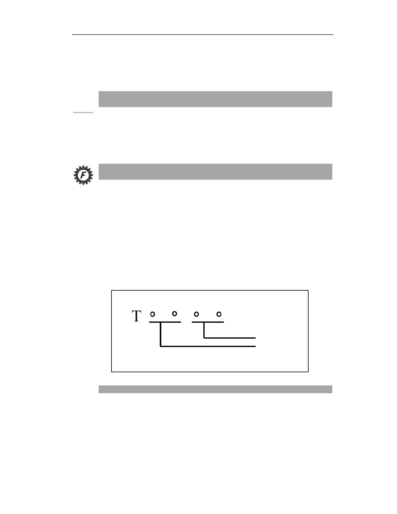
The format of T command is : T and the following 4 digits. See the figure below.
The first two digits is the tool number (the currently selected tool number)
The last 2 digits is the tool offset number (the number of the register where the offset is stored
and the number of the register where the radius compensation is stored)
Tool offset number
Tool No. selection
Description
1. Tool offset compensation setting
One tool needs to use one tool number, and one tool nose position needs to use one tool offset
number. When the tool has only one tool nose position, the tool number and tool offset number
are generally the same number for easy memory, such as T0101. When a tool has multiple tool
nose positions to be used, a tool number needs to correspond to multiple offset numbers. To
13
facilitate memory, the unit digit value of the tool number generally keep the same with that of the
tool offset number, such as T0202, T0212, T0222.
2. Cancel tool offset compensation
When the offset number is set to 00, it means that the tool offset function is cancelled and the
offset is 0.
3. Relative offset compensation and absolute offset compensation
There are two modes of the tool offset value: incremental offset and absolute offset
Incremental offset
The position deviation of each tool nose relative to the standard tool nose. In this mode, the
program also needs a command to call the positional relationship between the standard tool
and the workpiece zero (such as the G92 command).
Absolute offset
When each tool is at the machine zero (the machine returns to zero and the tool is at the
machining position), the position deviation of the workpiece zero relative to the nose of each
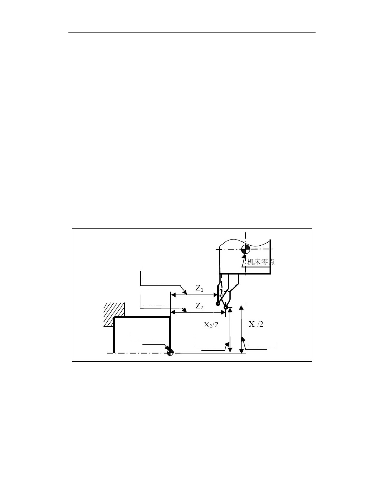
tool is shown as below:
Machine zero
No.1 tool offset on Z
No.2 tool
offset on Z
Workpiece zero
No.2 tool
No.1 tool
offset on X
offset on X
The HNC8 system adopts the absolute offset compensation mode. In the above figure, the absolute
offset value of No. 1 tool is: X axis X1 (diameter value), Z axis Z1; the absolute offset value of
No. 2 tool is: X axis X2 (diameter value), Z axis Z2.
During programming, the tool number and offset number of each tool are generally set to be the
same for user to remember. As shown in the figure above, T0101 and T0202 are used to execute
tool change and offset compensation. At this time, the offset values X1 Z1 of No. 1 tool must be
stored in the No. 1 offset compensation register, and the offset values X2 Z2 of No. 2 tool must
13
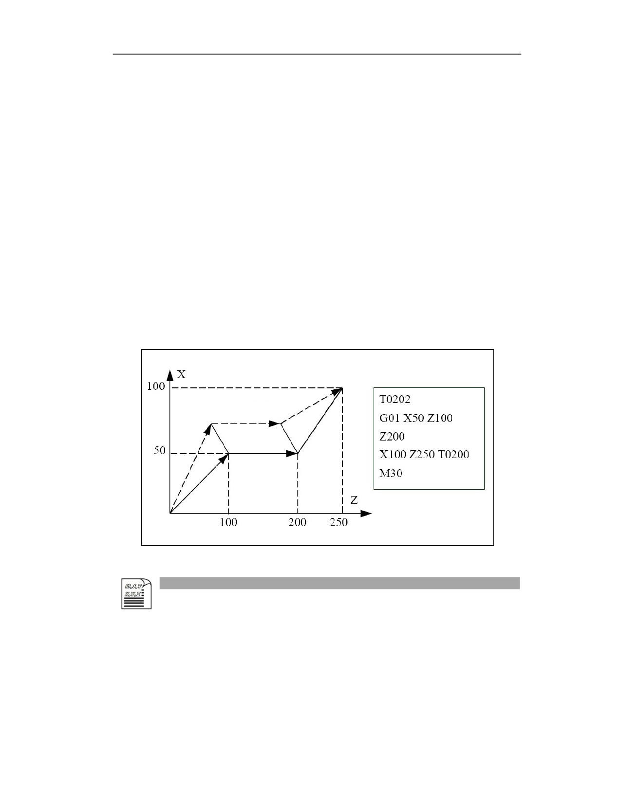
be stored in the No. 2 offset compensation register.
When the system executes the tool offset compensation, the machining coordinate system of No.1
and No.2 tools are set as (X1, Z1) and (X2, Z2) respectively. Therefore, though the geometric
dimensions of tools 1 and 2 are different, and the distances of both tools relative to workpiece
zero are different when tool post is at the machine zero, the coordinate system established for
each is coincident with the workpiece coordinate system.
4. Tool wear compensation
The error caused by tool wear is handled with wear compensation. The system stores the wear
compensation amount and the offset compensation amount in the same register address number.
Therefore, when the T command is used for offset compensation in the program, the position
offset and wear stored in the register will be called for compensation.
5. Tool path for tool offset and wear compensation
The figure below shows the tool position point trajectory for the situation: first establishing the
tool offset and the wear compensation, and then canceling the tool offset and the wear
compensation.
Tool compensation path
Programmed path
Example
N1 G00X100Z140
N2T0313 (No. 3 tool and No. 13 tool offset is selected)
N3X200Z150
As shown in the figure below, if the tool path has compensation values in the X and Z directions
relative to the programmed path (the vector composed of the compensation components in the X
and Z directions is called the compensation vector), then the end position in the block is added or
subtracted by the compensation amount (compensation vector) specified by the T code is the end
13
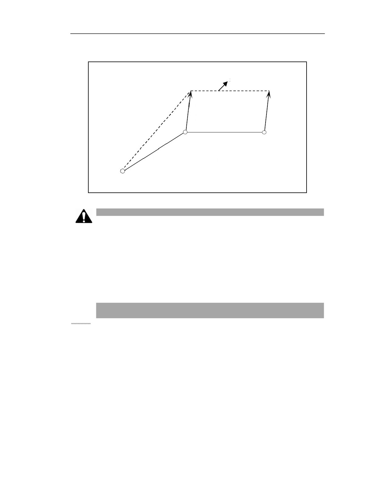
position of the tool path section.
Compensation path
Compensation vector (composed
of components on X and Z
Programmed path
Block including T code
Note
1) The tool offset compensation value can be automatically generated through the tool setting
operation, or it can be manually input into the offset compensation register after tool setting and
calculation. Please refer to the operation manual for specific operations.
2) Both the wear value and the offset value will be included in the program. If they are not needed,
be sure to set to 0.
12.2
Turning Tool Nose Radius Compensation(G40/G41/G42)(T)
Function and Purpose
The CNC program is generally aimed at a certain point on the tool which is the tool position to
compile the path of the tool. The tool position of the turning tool is an imaginary tool nose point
in an ideal state. This point is small enough and strong enough, and the workpiece contour is
finally machined by this point. However, due to process or other factors, the actual lathe tool nose
is often not an ideal point but a circular arc, so the actual cutting point of the tool (the final contact
point between the tool and the workpiece) will be changed on the circular arc of tool nose. This
position deviation between the actual cutting point and the tool position will inevitably cause
overcutting or undercutting of the workpiece, as shown in the figure below.
13
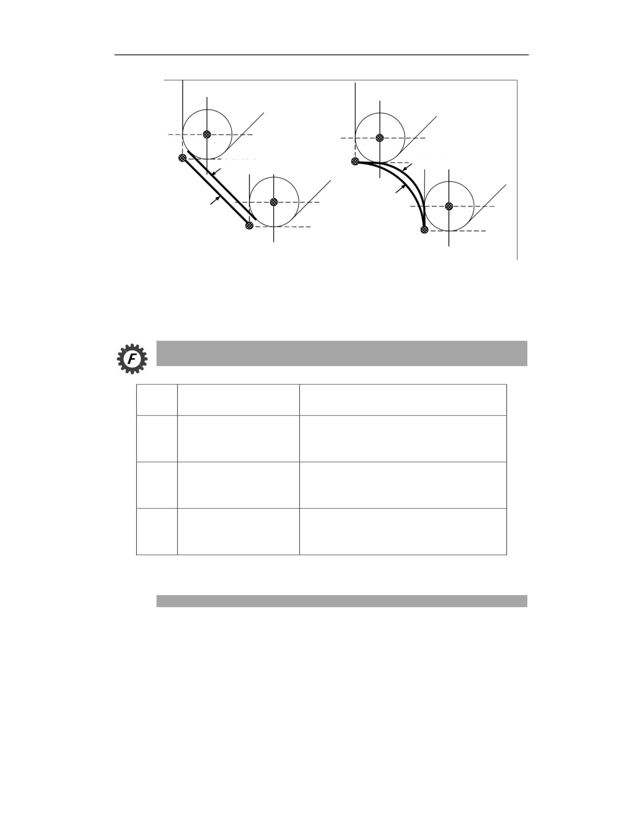
Actual contour
Actual contour
Programmed path
Programmed path
The machining error caused by the tool nose being not an ideal point but a circular arc can be
eliminated by the tool nose radius compensation function.
Command Format
G code
Workpiece position
Tool path
G40
Tool nose radius
Move along tool path
compensation is cancelled
G41
Tool nose radius
The left of the programmed path is compensated.
compensation left
G42
Tool nose radius
The right of the programmed path is compensated.
compensation right
Note: Radius compensation does not support the programs in interrupt format, such as G31.
Description
1. Imaginary tool nose point
The imaginary tool nose point during programming;
The point is assumed to be small enough and strong enough during programming, without
interference and cutting point position change;
The contour of the workpiece is formed by the final processing trajectory of this point;
13
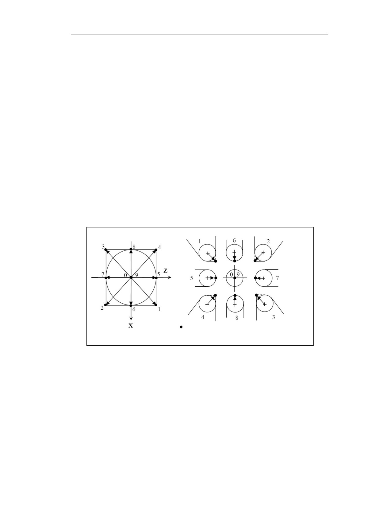
This point is the description point of the programmed path;
2. Tool position
Standard imaginary tool nose point;
This point is the description point of programmed path;
This point is the tool setting point;
9 positions can be used as the tool position for each tool nose. There are a total of 10 numbers
of tool position;
No. 0 and No. 9 tool positions are the circular center of the tool, and the other No. 1 to 8 tool
positions respectively correspond to a point position;
The main principle of tool position selection is ease of operation;
According to the numbering rules of tool position, there is a certain difference in the visual
expression of tool positions between machine tools with front tool post and with rear tool
post
3. Tool position of machine tool with front tool post
represents the tool position point A, + represents the tool nose
center O
4. Tool position of machine tool with rear tool post
14
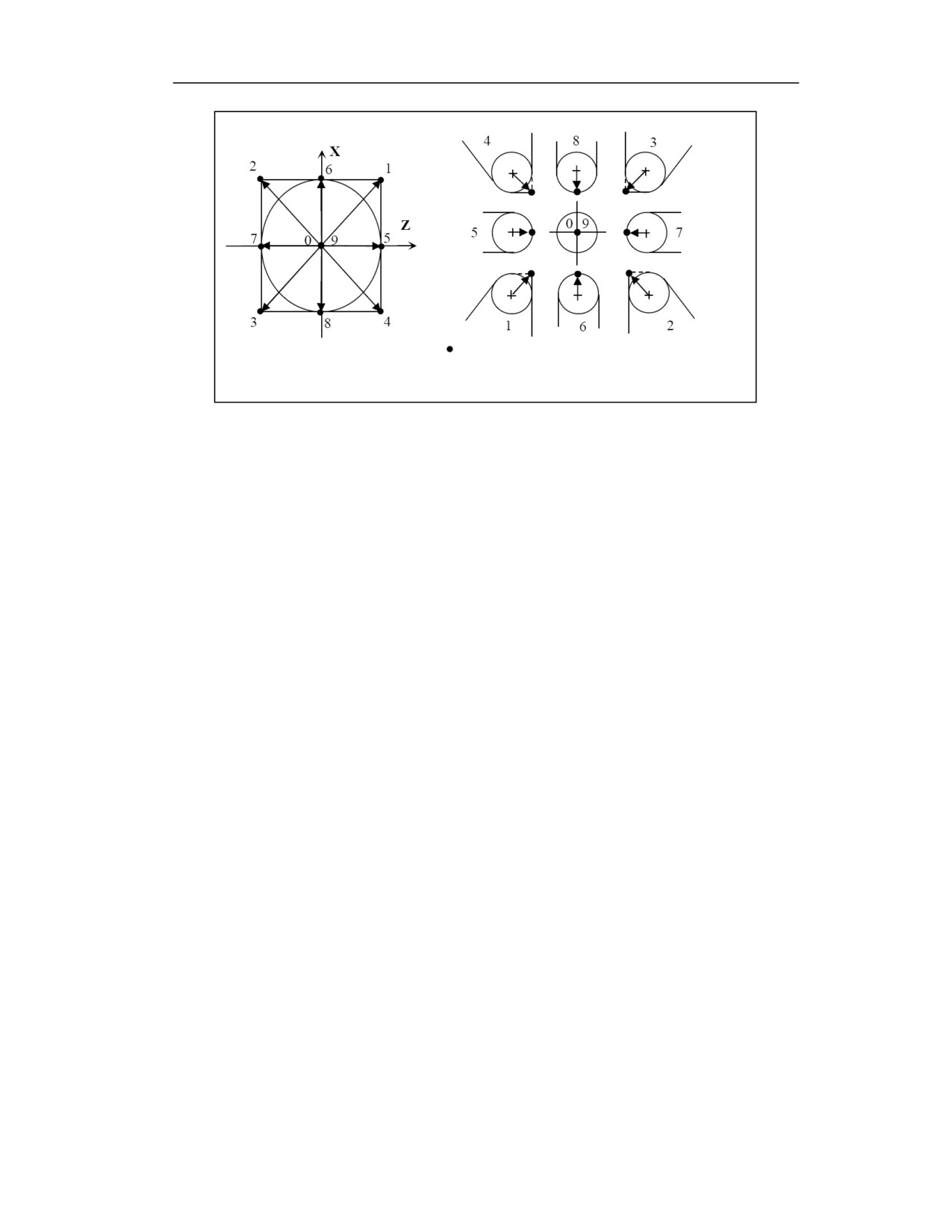
represents the tool position point A, + represents the tool nose
center O
5. Tool nose radius compensation left/right(G41\G42)
How to determine the right or the left,
G41(compensation left
:On the positive side of the third axis, user views
along the direction of tool movement, when the tool is on the left side of the
tool path, tool nose radius compensation left is determined.
G42(compensation right):On the positive side of the third axis, user views
along the direction of tool movement, when the tool is on the right side of the
tool path, tool nose radius compensation right is determined.
Tool nose radius compensation left/right for machine tool with front tool post and rear tool
post
Because the direction of the third axis for machine tools with the front and rear tool post, the
directions of the tool nose radius compensation are different. The third axis of the machine
tool with rear tool post points to the same direction as the customary direction; the third axis
direction of the machine tool with front tool post is opposite to the customary direction. See
the figure below for details
Figure of tool nose radius compensation for tool machine with front tool post
14
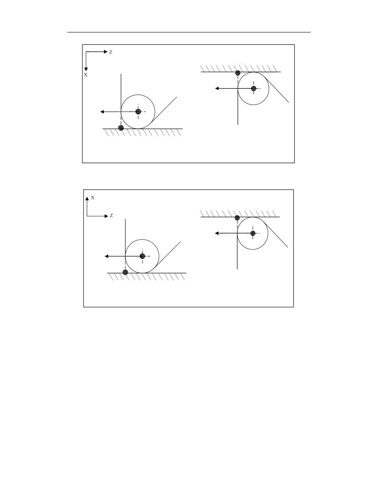
Workpiece side
Left compensation G41
Tool movement
Tool movement
direction
direction
Right compensation G42
Workpiece side
Figure of tool nose radius compensation for tool machine with rear tool post
Workpiece side
Left compensation G42
Tool movement
Tool movement
direction
direction
Right compensation G41
Workpiece side
6. Add or cancel tool nose radius compensation
The tool radius compensation can only be added or cancelled in the G00 or G01 block. When
it is added or cancelled in the G02 or G03 block, the system will alarm;
When adding or canceling tool radius compensation, it must be in the traverse command
block and there is enough moving distance, otherwise overcutting will occur;
When adding tool radius compensation, user needs to specify the corresponding tool nose
radius compensation value. The register for storing the radius compensation value has the
same number as the offset compensation register, so the tool offset number must be specified
with the T command;
After the execution of the tool radius compensation (G41/G42) block is completed, the center
of the tool stops directly above the normal direction of the starting point of the lower path.
14
Before executing the block of canceling tool radius compensation (G40), the center of the
tool stops directly above the normal direction of the end point of the upper path.
Cancel
Add
Workpiece side
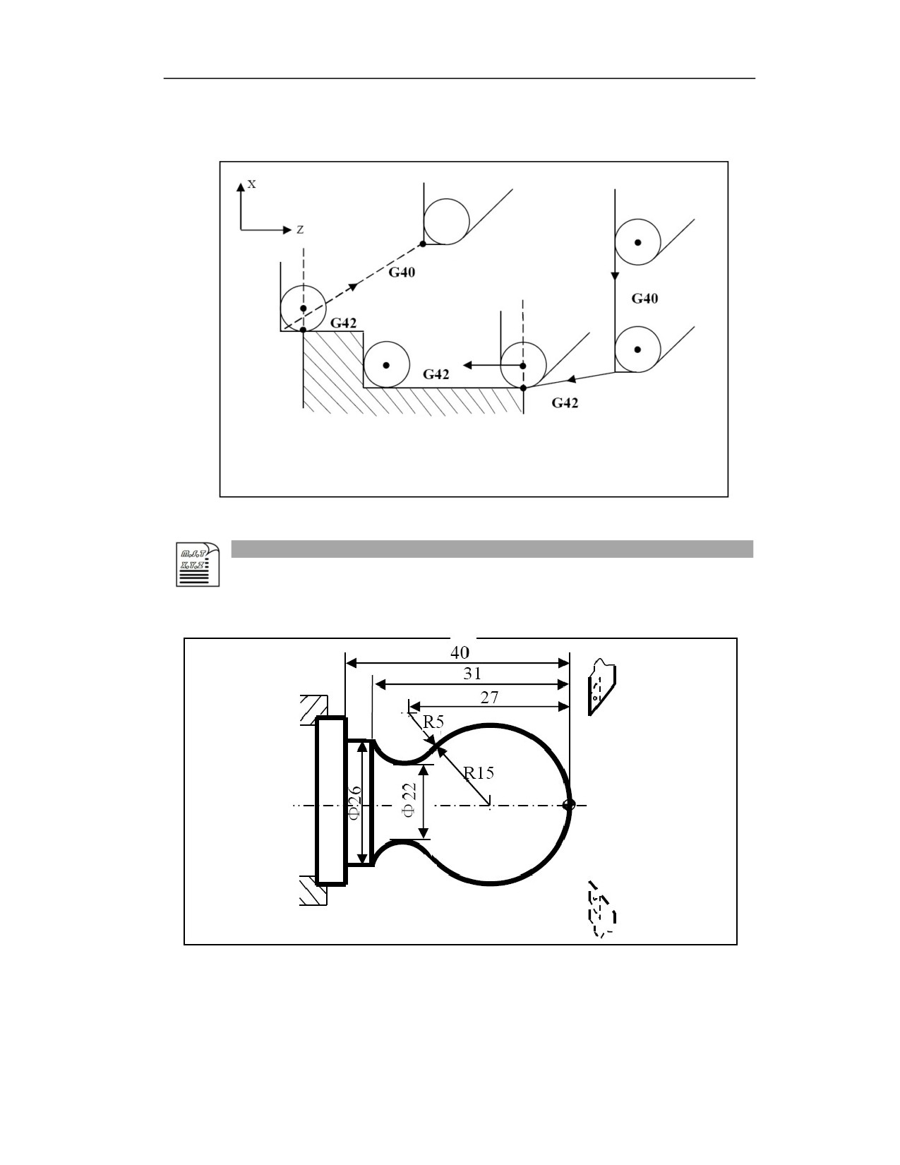
Example
Programming for the parts shown in below figure with tool radius compensation.
%3323
N1 T0101
(Change to the No. 1 tool and determine its coordinate system)
N2 M03 S400
(Spindle rotates CW at 400r/min)
14
N3 G00 X40 Z5
(Move to the starting position of program)
N4 G00 X0
(Tool moves to the workpiece center)
N5 G01 G42 Z0 F60
(Tool radius compensation is added, and move close to workpiece)
N6 G03 U24 W-24 R15
(Process R15 arc)
N7 G02 X26 Z-31 R5
(Process R5 arc)
N8 G01 Z-40
(Process Φ26 outer circle)
N9 G00 X30
(Exit the processed surface)
N10 G40 X40 Z5
(Cancel radius compensation, return to the starting position of program)
N11 M30
(Spindle stops, main program ends and resets)
Note
(1) G40, G41, and G42 are all modal codes, which can be mutually cancelled.
(2) Only G00 or G01 instead or G02 or G03 can be used for the creation and cancellation of tool
nose radius compensation.
(3) When using G41 or G42 to enable radius compensation, the corresponding radius
compensation register with radius compensation value must be designated. The radius
compensation register number is the same as the tool offset compensation register number.
(4) There must be a traverse command and a traverse distance in the block where the tool radius
compensation Enable (G41/G42) or the tool radius compensation Disable (G40) is added.
12.3
Milling Tool Length Compensation(M)
Function and Purpose
It is to set the difference between the tool length during programming and the actual tool length
in the tool length compensation register. Calling this function can move the tool to the
programmed end position without modifying the program, thus making the program universal.
14
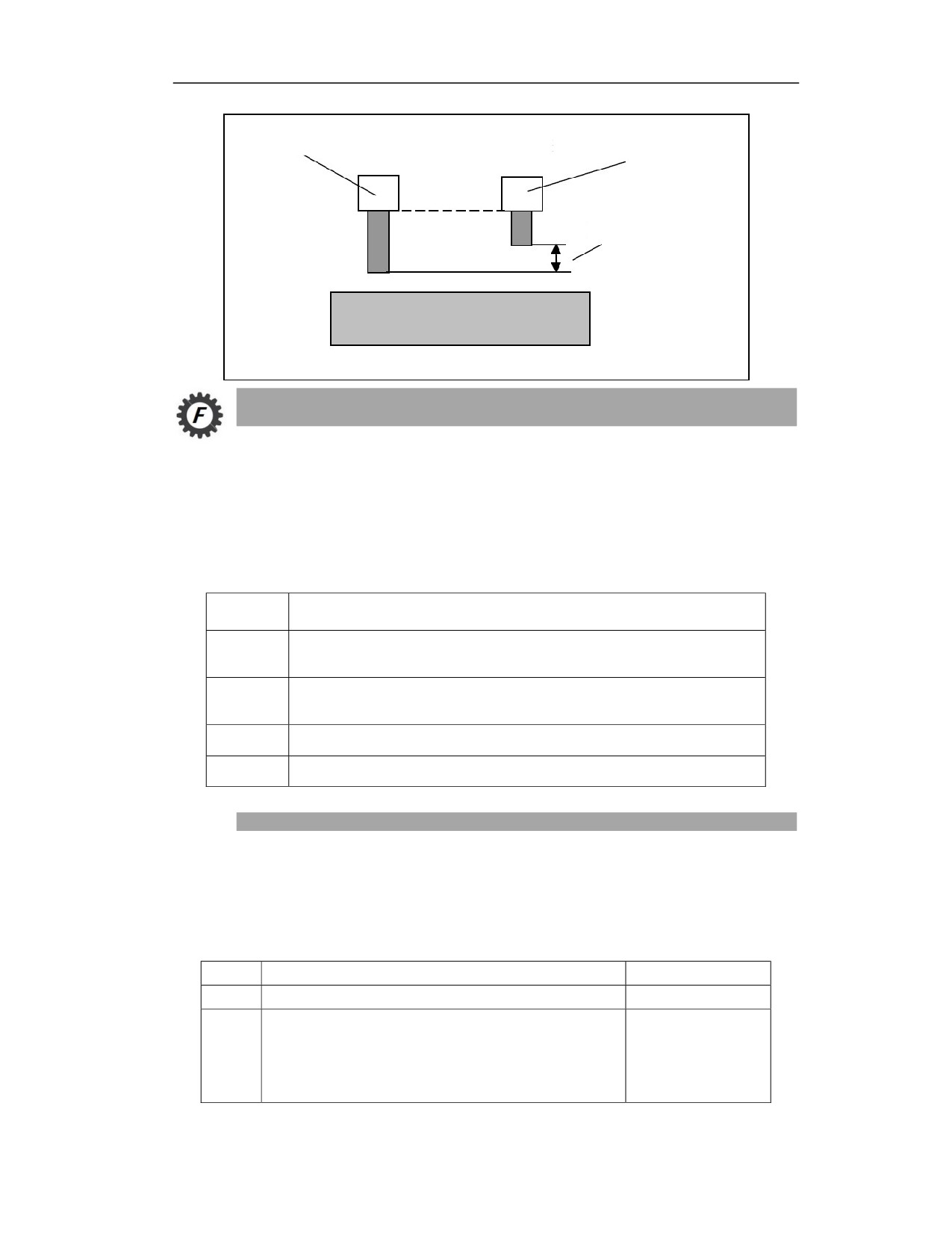
Tool used in programming
Actually used tool
Tool length compensation
Command Format
G43/G44 H_ Z_
…...
G49
Tool length compensation is specified with G43 and G44.
Parameter
Meaning
Tool length compensation plus (The tool length compensation value is added to
G43
the theoretical position in the tool axis direction)
Tool length compensation minus (The tool length compensation value is
G44
subtracted from the theoretical position in the tool axis direction)
H
The number of tool length compensation amount in the tool compensation table
G49
Cancel tool length compensation
Description
Tool length compensation type
(1) According to the tool length compensation axis, the following two tool length compensation
types can be used,
Type
Description
Format
A
Tool length compensation along basic Z axis
G43/G44 Z_H_
Tool length compensation along the vertical direction of the
G17 G43/G44 Z_H_
selected plane
B
G18 G43/G44 Y_H_
G17:XY plane;G18:ZX plane;
G19 G43/G44 X_H_
G19:YZ plane;
14
(2) The tool length compensation types A and B are set by the parameters, and the related
parameter are as below,
Parameter
Description
000012
Tool axis selection mode
000012:This parameter is used to determine which axis the G43/G44 tool length compensation
function should be performed on.
0: The tool length compensation is always performed on Z axis;
1: Tool length compensation axis is switched based on the coordinate plane selection
(G17/G18/G19) corresponding to Z/Y/X-axis respectively.
Movement amount of tool length compensation
(1) Movement amount of tool length compensation: when G43 or G44 tool length compensation
is executed, the movement amount is calculated according to the below formula:
G43 Z_ H_;Z_ + H_(tool length compensation)Compensaiton in + direction
G44 Z_ H_;Z_- H_(tool length compensation) Compensation in - direction
As shown in the above calculations, regardless of whether the absolute command or the
incremental value is used, the actual end point is of the coordinates which is compensated with
the specified compensation amount based on the end point coordinates of programmed traverse
command
(2) When there is length wear in the tool compensation table: for the execution of tool length
compensation command G43 or G44, the movement amount is calculated according to the
following formula
G43 Z_ H_;Z_ + H_(tool length compensation)+ H_(tool length wear)
G44 Z_ H_;Z_- H_(tool length compensation)- H_(tool length wear)
(3) When there is coordinate value in the workpiece coordinate system: for the execution of tool
length compensation command G43 or G44, the movement amount is calculated according to the
following formula
G43 Z_ H_;Z(workpiece coordinate system)+ Z_ + H_(tool length compensation)
G44 Z_ H_;Z(workpiece coordinate system)+ Z_- H_(tool length compensation)
(4) When there is coordinate value in the workpiece coordinate system and length wear in the tool
compensation table: for the execution of tool length compensation command G43 or G44, the
movement amount is calculated according to the following formula
G43 Z_ H_;Z(workpiece coordinate system)+ Z_ + H_(tool length compensation)+ H_
(tool length wear)
G44 Z_ H_;Z(workpiece coordinate system)+ Z_- H_(tool length compensation)- H_(tool
14
length wear)
(5) When there is coordinate value in the workpiece coordinate system, and there is a coordinate
value of external zero offset: for the execution of tool length compensation command G43 or G44,
the movement amount is calculated according to the following formula
G43 Z_ H_;Z(workpiece coordinate system)+ Z(external zero offset)+ Z_ + H_(tool length
compensation)
G44 Z_ H_;Z(workpiece coordinate system)+ Z(external zero offset)+ Z_- H_(tool length
compensation)
(6) When there is coordinate values in workpiece coordinate system and external zero offset, and
there is length wear in the tool compensation table: for the execution of tool length compensation
command G43 or G44, the movement amount is calculated according to the following formula
G43 Z_ H_;Z(workpiece coordinate system)+ Z(external zero offset)+Z_ + H_(tool length
compensation)+ H_(tool length wear)
G44 Z_ H_;Z(workpiece coordinate system)+ Z(external zero offset)+Z_- H_(tool length
compensation)- H_(tool length wear)
Tool length compensation number
(1) The working range of the compensation number depends on the parameter setting. The
relevant parameters are as follows:
Parameter
Description
000060
Number of tools stored in system
NC000060: This parameter is to set the number of tool of which the data (tool offset, wear, radius,
tool nose direction, etc.) is saved in the tool compensation table. The value must be greater than
or equal to the sum of the tools in each channel.
Max. value:1000 Default:100 Min. value:0
(2) When the commanded compensation number exceeds the range, the system will give an alarm
of "illegal tool compensation number".
(3) After the compensation number specified in G43 or G44 block, it cannot become the modal
called later to be effective.
For example, H1 modal in N1 line cannot take effect in N4 line in the following program.
N1 G43 Z0 H1; Perform tool length compensation via H1
N2 G0 X0 Y0;
N3 G49 Z0; Tool length compensation is cancelled
N4 G43 Z0; Tool length compensation will not be performed through H1 again, and the
compensation number must be specified again.
14
(4) In the G43/G44 modal, when G43/G44 is commanded again, the compensation will be
performed according to the new compensation number, that is, the new offset value will not be
added to the old offset value when the offset number is changed.
For example, the N2 line of the following program is compensated according to the new
compensation number H2.
N1 G43 Z0 H1; Tool length compensation is performed via H1
N2 G43 Z0 H2; Tool length compensation is performed with the new compensation number
H2
Cancel the tool length compensation
(1) After the system restarts and M02, M30, G49 are executed, tool length compensation is
cancelled.
(2) H0 is specified, tool length compensation is cancelled.
(3) When Reset or Emergency Stop is pressed during tool length compensation modal, tool length
compensation is cancelled.
(4) When tool length compensation type B is used, the following items must be noted for
canceling tool length compensation with G49.
(a) When the length compensation is cancelled with G49, only the length compensation in
the last selected plane before G49 command is cancelled;
For example, in the below program, G49 in N6 line only cancels the length compensation in
G19 plane.
N1 G28 X0 Y0 Z0;
N2 G92 X0 Y0 Z0;
N3 G17 G43 Z0 H1; Tool length compensation in XY plane is performed via H1
N4 G18 G43 Y0 H2; Tool length compensation in ZX plane is performed via H2
N5 G19 G43 X0 H3; Tool length compensation in YZ plane is performed via H3
N6 G49;
The length compensation only in G19 plane is cancelled
N7 G0 X0 Y0 Z0;
(b) When using G49 to cancel the length compensation in all planes, the plane selection
command (G17/G18/G19) must be specified after the G49 command, and it must be specified
in a separate line;
For example, the correct programming based on the above is as following
N1
or
N1
14
N6 G49 G17;
N6 G49 G17;
N7 G49 G18;
N7 G18;
N8 G49 G19;
N8 G19;
N9
N9
Wrong way: G49 G17 G18 G19, only the length compensation in the last plane selected
before the G49 command.
Actions when other commands are executed in the tool length compensation modal
(1) Whether the tool length compensation will be restored after G53 or G28 is executed in the tool
length compensation modal depends on the parameter setting. The relevant parameters are as
follows:
Parameter
Description
000014
Whether tool length compensation is restored after
G53/G28
000014:This parameter is to set whether to automatically restore the tool length compensation
function after executing G53/G28 commands.
0: After executing G53/G28 command, the tool length compensation function will not be
restored automatically.
1: After executing G53/G28 command, the tool length compensation function will be
restored automatically.
(2) Whether the tool length compensation will be restored after the G30 command is executed in
the tool length compensation modal depends on the setting of parameter 000014
(3) When G29 is executed in tool length compensation modal, the tool length compensation will
not be cancelled, and cannot be controlled by 000014 parameter.
For example,the machine coordinate is Z55.0 after N4 line is executed when H1=50 in the
following program
N1 G28 Z10;
N2 G90 G92 Z0;
N3 G43 Z0 H1; Tool length compensation is performed via H1.
N4 G29 Z5; Machine coordinate is Z55.0. Machine coordinate is Z-45.0 when G44 is used.
N5 G49; Tool length compensation is cancelled.
(4) When G54 to G59 commands are executed in the tool length compensation modal to change
the workpiece coordinate system, the tool length compensation will not be cancelled, and the end
point coordinates of the compensation axis will be recalculated based on the given coordinate
system.
14
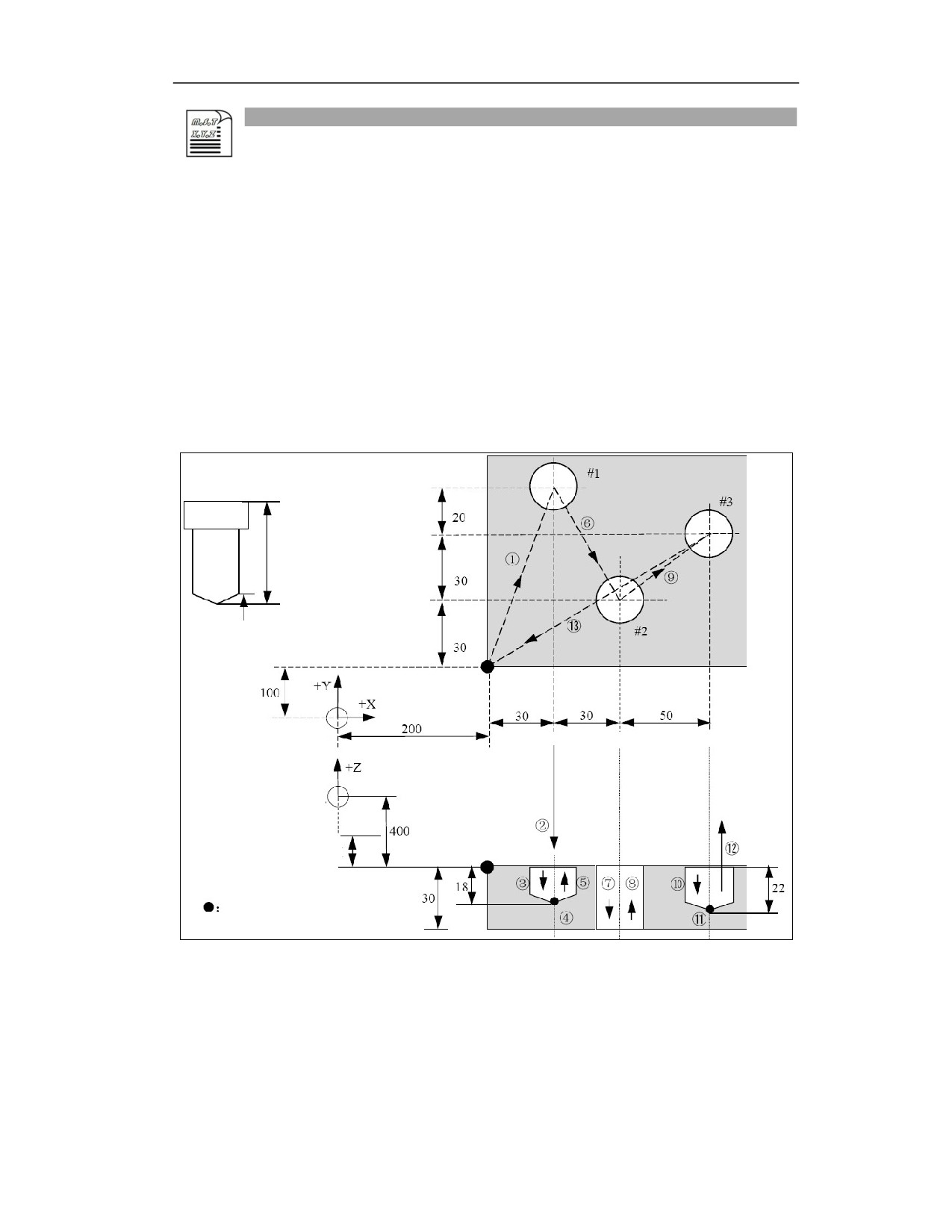
Example
Create the machining program for the parts shown in the figure below with tool length
compensation. Requirements are as follows:
(1) Set the workpiece coordinate system in the G54 coordinate system based on the workpiece
zero as shown in the figure
(2) Process according to the path 1 to 13 indicated by the arrow
(3) Write out the coordinate value in the workpiece coordinate system and the compensation value
in the tool compensation table before programming
(4) Write the comment and machine coordinate of each line of program
(5) The program must be safe and reliable
Tool length=120mm
Tool nose=4mm
Machine origin
Machine origin
Tool length
Workpiece origin
Workpiece coordinate system:G54(X200,Y100,Z-280) Compensation value:H01=-
120
%1234
G54 G90 M03 S600
; Select workpiece coordinate system G54, use absolute command G90
to program, spindle rotates CW
G00 Z50
;Rapid traverse to Z50, (Z-230)
15
X0 Y0
;X0 Y0, Rapid traverse to X0 Y0, (X200,Y100)
X30 Y80
;①, Rapid traverse to X30 Y80(X230,Y180)
G43 Z5 H01 ;②, Establish tool length compensation, and rapid traverse to Z25, (Z-395)
G01 Z-18 F300
;③, Z-18Process #1 hole to Z-18,(Z-418)
G04 P2000
;④, Pause for two seconds at the bottom of the hole
G00 Z5
;⑤, Rapid traverse to Z5,(Z-395)
X60 Y30
;⑥, Rapid traverse to X60 Y30,(X260,Y130)
G01 Z-40
;⑦, Process #2 hole to Z-40,(Z-440)
G00 Z5
;⑧, Rapid traverse to Z5,(Z-395)
X110 Y60
;⑨, Y60Rapid traverse to X110 Y60,(X310,Y160)
G01 Z-22
;⑩, Process #3 hole to Z-22,(Z-422)
G04 P2000
;⑪, Pause for two seconds at the bottom of the hole
G49 G0 Z50 ;⑫, Cancel the tool length compensation, and rapid traverse to Z50, (Z-230)
X0Y0
;⑬, Rapid traverse to X0 Y0,(X200,Y100)
M05
; Spindle stops
M30
; Program ends
Note
(1) The direction of tool length compensation is always perpendicular to the plane selected by
G17/G18/G19.
(2) The compensation number H_ must be given after G43/G44 command, otherwise the system
will issue an alarm of "No compensation number specified".
(3) The compensation axis (X/Y/Z) must be specified after G43/G44 command, or the traverse
command of compensation axis must be specified before the next G43/G44 command, otherwise
the length compensation will be invalid.
(4) G43/G44/G49 are all modal codes and can be mutually cancelled, but they can be mutually
cancelled only when they are not specified in the same line. When G43 and G44 are specified in
the same line, the system will alarm; when G49 is specified in the same line as G43/G44, G49
will not take effect.
(5) G43/G44/G49 For G43/G44/G49, after startup, emergency stop and reset, G49 state is the
default.
(6) When using G43/G44 to specify H0, the tool length compensation will be cancelled, but the
modal display area is still G43/G44, and will not be changed to G49, so when H_ is given
separately at this time, the tool length compensation will take effect again.
(7) When G49 is not used, use H0 to cancel the tool length compensation, and then add the tool
length compensation with H_; When H0 is used to cancel the tool length compensation, there is
no tool length compensation until H_ is used again.
For example,
15
N1 G43 Z0 H1
; Tool length compensation is performed with H1
N2 G43 Z0 H0
; Tool length compensation is cancelled with H0
N3 G0 Z5
; There is no tool length compensation
N4 H2
; Tool length compensation is performed with H2
N5 G0 Z0
; There is tool length compensation
N6 G49
; Tool length compensation is cancelled
(8) After the tool length compensation is set in MDI, it will always be valid for the subsequent
MDI program. The tool length compensation will only be cancelled after HO is specified with
reset, emergency stop and MDI, as well as G49 command being executed on MDI interface.
(9) After the tool length compensation is set in MDI, it will not be effective for the program in the
program file. After switching from the MDI interface to the program interface, the modal becomes
the G49 modal, so it will not be effective.
(10) When the G43/G44 tool length compensation program is stopped with reset or emergency
stop, the tool length compensation will be cancelled. When the program is stopped with the dwell
or switching mode, the tool length compensation will not be cancelled.
(11) After the tool length compensation is set with G43/G44, the tool length compensation will
be performed based on the corresponding H number.
(12) In the auto mode, when using the breakpoint save and restore functions after the tool length
compensation command, the system can correctly establish the tool length compensation after the
program resumes execution. If there are multiple G43/G44 tool length compensation commands
in the program, the system can also correctly establish tool length compensation through the
corresponding G43/G44 commands after the breakpoint is restored.
(13) After the tool length compensation command is used to specify the line operation with any
line function, the system can correctly establish the tool length compensation; If there are multiple
G43/G44 tool length compensation commands in the program, the system can also correctly
establish tool length compensation through the corresponding G43/G44 commands.
For example, when the following program runs from line N3 with any line function, the system
can correctly establish tool length compensation
N1 G43 Z0 H1
N2 G0 Z5
N3 G0 Z10; Use any line function to run from this line
N4 G0 Z15
N5 G0 Z20
N6 G49;
15
12.4
Milling Tool Radius Compensation(G40/G41/G42)(M)
Function and Purpose
When the CNC machine tool mills the contour of the workpiece, the tool center is usually used
as the path for easy programming. The tool radius is not considered when programming, and the
tool path is programmed based on the contour size of the workpiece. But there will be an offset
(tool radius) between the actual tool path and the workpiece contour. Therefore, the offset of the
tool center path is needed during programming to make the tool path consistent with the
workpiece contour, which is called tool radius compensation function.
In addition, the tool radius is changed due to tool change or tool wear. With this function, user
can directly modify the corresponding radius compensation value or wear value in the tool
compensation table without modifying programming.
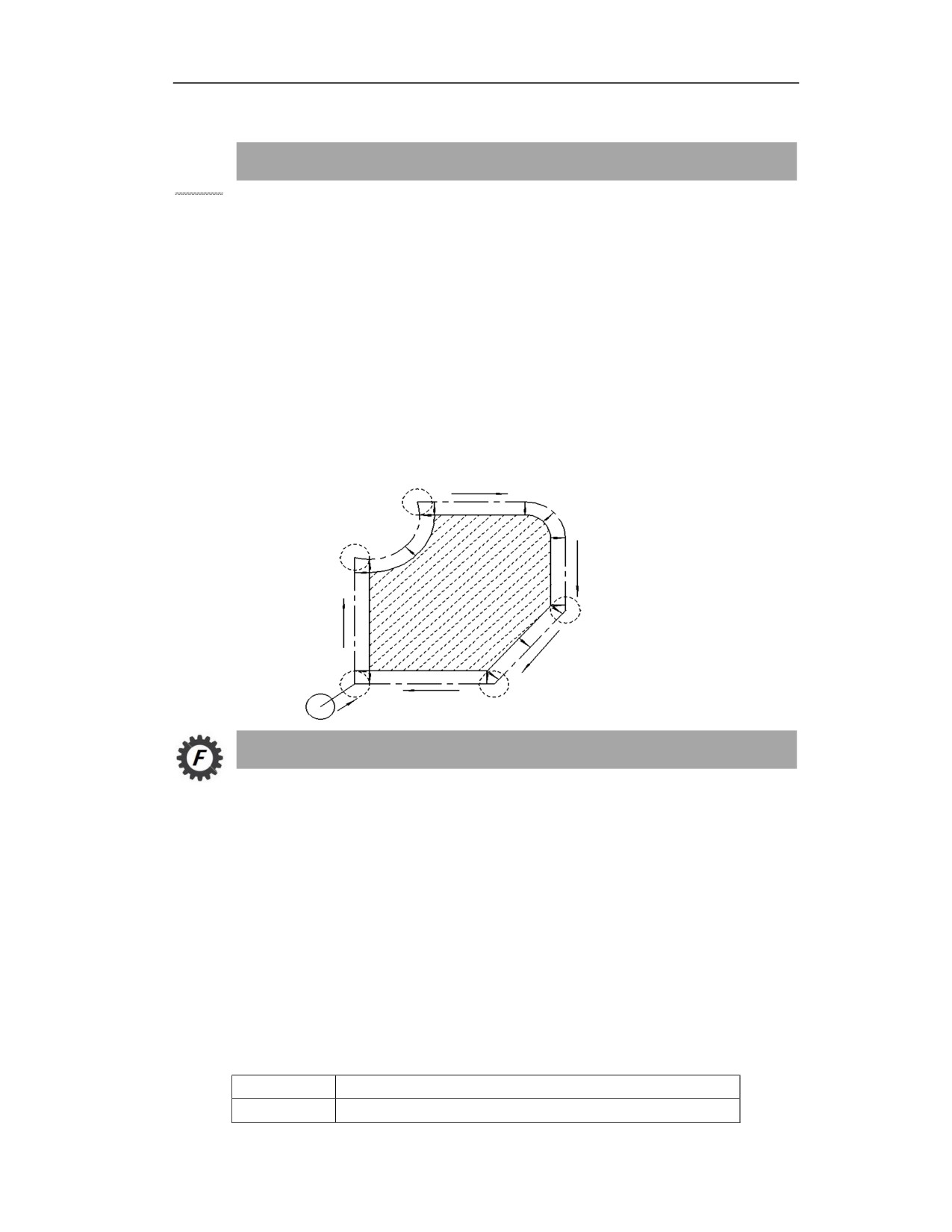
After the tool radius compensation is performed, the tool path is shown as the dotted line in the
figure below:
Command Format
G00 X_ Y_ D_
G17 G41/G42
{
G01 X_ Y_ D_
G00 X_ Z_ D_
G18 G41/G42
{
G01 X_ Z_ D_
G00 Y_ Z_ D_
G19 G41/G42
{
G01 Y_ Z_ D_
Parameter
Meaning
G17/G18/G19
To specify compensation plane, XY, XZ, ZY-plane respectively.
15
Tool radius compensation is valid. G41: Tool radius compensation
G41/G42
Left; G42: Tool radius compensation Right
D
To specify the compensation number
Description
1) Tool radius compensation direction
Tool compensation path
Description:
G41 Tool radius compensation Left
Viewed from the positive direction to the negative
direction of the third axis that is not in the machining
Programmed path
plane, the tool is on the left side of the workpiece
relative to the direction of tool movement
Left compensation
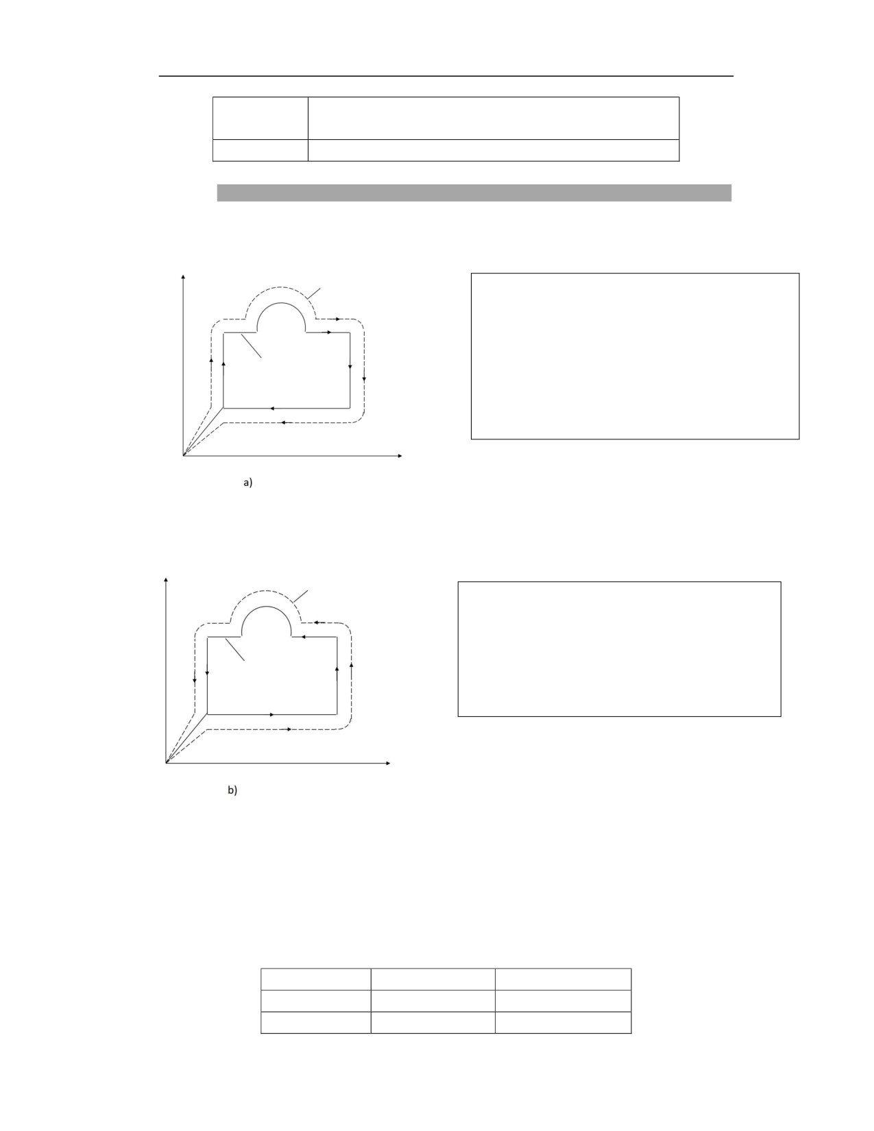
G41:Offset is performed to the left side of the tool path (as shown in the figure a below).
G42:Offset is performed to the right side of the tool path (as shown in the figure b below).
Tool compensation path
Description:
G42 Tool radius compensation Right
Viewed from the positive direction to the negative
direction of the third axis that is not in the machining
Programmed path
plane, the tool is on the right side of the workpiece
relative to the direction of tool movement
Right compensation
2) Tool radius compensation number
The effective range of tool compensation numbers in this system defaults to 99 groups, and the
effective range of compensation numbers can be set by NC parameter 000060 (number of tool
data saved by the system).
3) Tool radius compensation plane selection
Offset plane
Plane selection
IP
XY
G17
X_Y_
ZX
G18
X_Z_
15
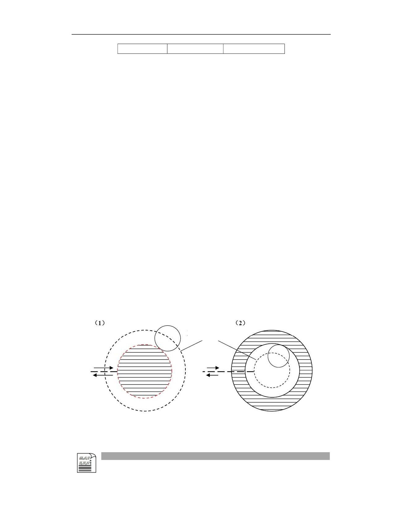
YZ
G19
Y_Z_
The radius compensation calculation is performed on the plane determined by the G17/G18/G19
commands. The plane on which the compensation calculation is performed is called the
compensation plane. The axis coordinate values that are not in the compensation plane will not
be compensated. The projection of the tool path in each plane is compensated at the time of
simultaneous 3-axis control.
The compensation plane must be switched when radius compensation is cancelled. If the plane is
switched during compensation, the alarm "Coordinate plane cannot be switched during tool radius
compensation" will appear and the machine tool will stop.
4) Tool radius compensation amount setting
Use the D code to call the compensation amount set in the tool compensation table by specifying
the number of the tool radius compensation amount.
The D code remains valid until another D code is designated.
The change of the tool radius compensation amount is usually carried out in the G40, reset or tool
change mode.
In general, the compensation amount is positive (+). If the compensation amount is negative (-),
G41 and G42 are interchanged. If the compensation amount is positive, the tool center moves
around the outer contour of the workpiece, then if the compensation is negative, it will move
around the inner side, as shown in the figure below.
When the compensation amount is positive, the tool path is shown in Figure (1). If the
compensation amount is changed to a negative value (-), the tool path is shown in Figure (2).
Therefore, for the same program, both male and female shapes can be processed by the positive
and negative values of the compensation, and the gap between them can also be adjusted with the
compensation.
Tool center path
Example
15
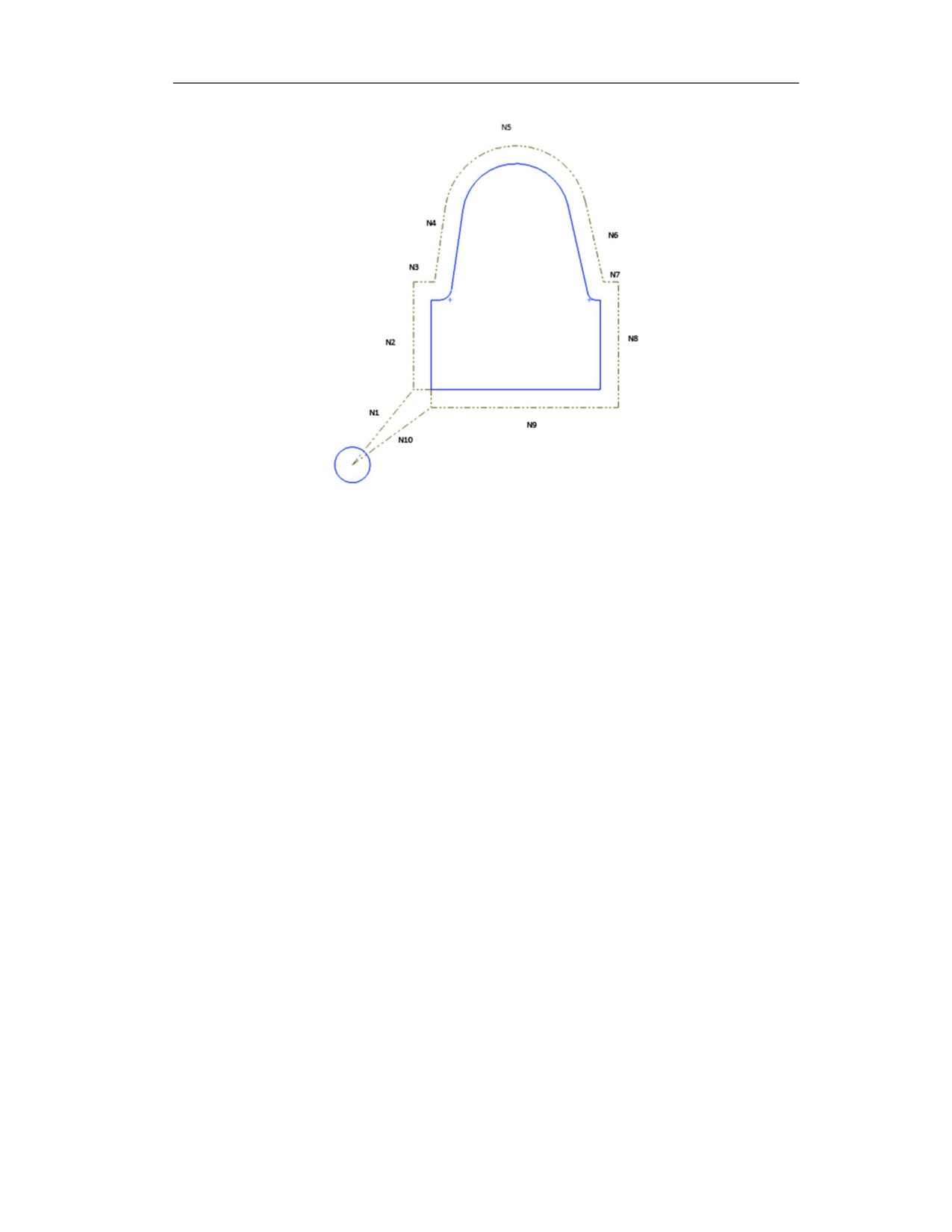
Starting position
G92 X0 Y0 Z0; The absolute value is specified, and the tool is at the starting point
N1 G90 G17 G00 G41 D01 X25 Y25; Tool radius compensation (tool starts) starts
N2 G01 Y50 F150; Process from N2
N3 X30; Process from N3
N4 G03 X40 Y60 R10.0; Process from N3 to N4
N5 G01 X50 Y90; Process from N4
N6 G02 X90 Y90 R20; Process from N5
N7 G01 X100 Y60; Process from N6
N8 G03 X110 Y50 R10; Process from N6 to N7
N9 G1 X120; Process from N7
N10 X120 Y25; Process from N8
N11 X25 Y25; Process from N9
N12 G00 G40 X0 Y0; Cancel tool radius compensation, and tool returns to the starting
position (X0,Y0,Z0)
15
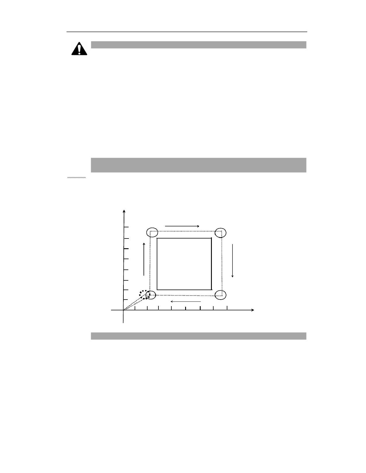
Note
1) The length compensation H command is ignored in the tool radius compensation, and only the
D command is valid.
2) The plane selection for tool radius compensation is specified by G command (G17/G18/G19),
and only the axes in the specified plane are compensated, the axes not in the plane are not
compensated.
12.5
Detailed Explanation of Tool Radius Compensation
12.5.1 Tool Radius Compensation Action
Function and Purpose
The process of tool radius compensation is divided into three steps: tool compensation
establishment, tool compensation in progress and tool compensation cancelation. As shown below:
Description
Tool radius compensation establishment and start
When the compensation is canceled, and the radius compensation command is used to establish
tool radius compensation, if the following compensation establishment conditions are not met,
there may occur compensation overcutting, undercutting or alarms.
(1) The establishment of tool radius compensation mode is valid only in G00/G01 traverse
command mode;
(2) The tool radius must be established on the axis where movement distance is not 0 in the
15
compensation plane. The compensation cannot be established when only the third axis movement
is performed; however, in special cases, the system also supports the establishment of tool
compensation with a movement amount of 0, and in order to prevent errors, it is recommended to
give a movement greater than the tool radius value when creating tool compensation.
(3) The establishment is usually performed with G01 to ensure the safety of the tool and workpiece
(4) When the sign of the compensation value changes, the compensation direction of G41/G42
will also change.When the compensation value of G41 is positive, the compensation direction is
on the left, and when the compensation value is negative, the compensation direction is on the
right. G42 is also like this.
(5) When using tangential cutting or normal cutting to establish tool compensation, if the
establishment conditions are not met, auxiliary line segments can be added to establish tool
compensation when cutting into the workpiece.
(6) The number of tool radius compensation is: 0<D<maximum compensation number.
(7) The establishment of tool radius compensation in circular interpolation (G02/G03) is invalid,
the system will alarm, and the machine stops moving
(8) In the process of radius compensation, G00
(rapid traverse positioning), G01
(linear
interpolation) or G02/G03 (circular interpolation) is used to realize compensation. If two or more
blocks where the tool does not move (such as auxiliary functions, pause, etc.) are executed during
radius compensation, there will occur overcutting or undercutting.
In the process of tool radius compensation
(1) When starting the radius compensation, whether it is in auto mode or single-block mode, three
traverse commands must be read in. If there is no three traverse commands, the execution will be
performed after reading up to 5 consecutive blocks.
(2) When the radius compensation is valid, the compensation plane must not be switched,
otherwise it will alarm and stop the movement.
(3) In the state of radius compensation, the linear movement of the milling cutter and the radius
for the inner circular cutting must be greater than or equal to the radius of the milling cutter,
otherwise it may cause interference and overcutting.
When tool radius compensation is cancelled
The cancellation of tool radius compensation needs to be executed in the G00 or G01 block. When
any of the following conditions is met, the system enters the radius compensation cancellation
state.
(1) When the machine is turned on, the system will initialize and restore the default tool
compensation cancellation state.
15
(2) After machine is reset.
(3) The tool compensation cancellation command G40 is executed.
(4) M02 and M30 commands with the reset function are executed.
(5) When the block where the tool radius compensation offset number is 0 is executed.
Example
%0001
G54G90G17G0Z50
X0Y0
M3S10000
G41G01X30Y20D01 ; Tool radius compensation is established, and register value of
No.1 tool compensation is called
Y70
X70
Y20
X30
G40G01X0Y0 ; Tool radius compensation is cancelled.
M30
Note
It is invalid when the radius compensation is cancelled by the circular command (G02/G03). If
the circular command is designated for the cancellation, an alarm will be issued and the machine
tool will stop moving.
12.5.2 Tool Radius Compensation Action Diagram
Function and Purpose
Inside and outside: When the included angle of the tool path established by two programs exceeds
180°, the path is referred to as "inside". When the included angle is between 0° and 180°, it is
referred to as "outside".
15